alberta guidelines for residential rainwater … | ii acknowledgements rainwater harvesting task...
TRANSCRIPT

Alberta Guidelines for Residential
Rainwater Harvesting Systems
2010
HANDBOOK


Page | i
Alberta Guidelines for Residential
Rainwater Harvesting Systems
2010
HANDBOOK In Alberta, the Alberta Building Code, National Plumbing Code, with select amendments, and the Canadian Electrical Code are the codes that are applicable to the design, construction and management of rainwater harvesting systems. This guidelines document and the accompanying handbook provide additional guidance for designing, constructing, and managing rainwater harvesting systems based on the minimum safety requirements established in these codes.
© Copyright, the Crown in right of Alberta,
as represented by the Minister of Municipal Affairs.
First Edition, July 2010
All rights reserved. No part of this document may be used or reproduced in any form or by any means, without the prior written permission of Alberta Municipal Affairs.
The use of this document is for information purposes only. While thought to be accurate, the information contained in the document is provided strictly "as is" and without warranty of any kind, either express or implied. While care has been taken to ensure accuracy, the examples and explanations in this document are for purposes of illustration and constitute opinion only. Any codes or regulations referenced in this document should be consulted for all purposes of interpreting and applying the law. Neither the Crown, its agents, employees nor contractors shall not be liable to any user for any losses, claims or damages that may result either directly or indirectly from access to or any reliance upon this document.

Page | ii
Acknowledgements
Rainwater Harvesting Task Group
The Alberta Guidelines for Residential Rainwater Harvesting Systems 2010 were developed with assistance from a Rainwater Harvesting Task Group made up of government and industry stakeholders. Task Group members represent the following stakeholder groups:
1. Alberta Municipal Affairs 2. Canada Mortgage and Housing Corporation 3. Canadian Water and Wastewater Association 4. City of Calgary 5. City of Guelph 6. Ecoshift 7. Evolve Builders Group Inc. 8. GE Water & Process Technologies 9. Interpump Supply Ltd.
10. Ontario Ministry of Municipal Affairs and Housing 11. Region of Durham 12. RH2O North America Inc. 13. Toronto and Region Conservation Authority
Task Group Members
Tyler Wightman Alf Durnie Sidney Manning Pierre McDonald Cate Soroczan T. Duncan Ellison Liliana Bozic Wayne Galliher David Auliffe
Geoff Jones Ben Polley Mark Myronyk Peter Follett Shane Gallagher Danny Hui Glen Pleasance Scott Robinson Tim Van Seters
Author
Christopher Despins, M.Sc. President Connect the Drops [email protected]
Editors
Chantelle Leidl, M.Sc. Khosrow Farahbakhsh, Ph.D., P.Eng Rainwater Harvesting Specialist Associate Professor University of Guelph [email protected]

Page | iii
Table of Contents Introduction ..................................................................................................................................... 1
What are the Permitted Uses of Rainwater? ............................................................................... 1
Chapter 1. Rainwater Catchment & Conveyance ........................................................................... 2
1.1 Introduction ...................................................................................................................... 2
1.2 Applicable Codes, Standards, and Guidelines ................................................................. 3
1.3 Issues for Consideration ................................................................................................... 4
Catchment Area ...................................................................................................................... 4
Catchment Material ................................................................................................................. 5
Rainwater Conveyance ........................................................................................................... 6
Size, Slope and Placement of Conveyance Network .............................................................. 7
Site Conditions and Tank Location ......................................................................................... 7
Conveyance Network Materials Selection .............................................................................. 8
Cold Weather Issues ............................................................................................................... 8
Rainwater Quality ................................................................................................................... 8
1.4 Design & Installation Guidelines ..................................................................................... 9
1.5 Management Guidelines ................................................................................................. 14
Chapter 2. Rainwater Storage & Tank Sizing ............................................................................... 15
2.1 Introduction .................................................................................................................... 15
2.2 Applicable Codes, Standards, and Guidelines ............................................................... 16
2.3 Issues for Consideration ................................................................................................. 17
General .................................................................................................................................. 17
Tank Location ....................................................................................................................... 17
Tank Placement ..................................................................................................................... 18
Tank Capacity ....................................................................................................................... 18
Cold Weather Issues ............................................................................................................. 19
Tank Material ........................................................................................................................ 20
2.4 Design & Installation Guidelines ................................................................................... 21
2.5 Management Guidelines ................................................................................................. 25
Chapter 3. Rainwater Quality & Treatment .................................................................................. 27
3.1 Introduction .................................................................................................................... 27
3.2 Applicable Codes, Standards, and Guidelines ............................................................... 28

Page | iv
3.3 Issues for Consideration ................................................................................................. 29
Rainwater Quality & Treatment Guidelines ......................................................................... 29
Factors Affecting Rainwater Quality .................................................................................... 29
Treatment Options ................................................................................................................ 30
Treatment Device Selection .................................................................................................. 34
Performance Issues with Treatment Devices ........................................................................ 34
3.4 Design & Installation Guidelines ................................................................................... 36
3.5 Management Guidelines ................................................................................................. 40
Chapter 4. Make-up Water System and Backflow Prevention ..................................................... 42
4.1 Introduction .................................................................................................................... 42
4.2 Applicable Codes, Standards, and Guidelines ............................................................... 43
4.3 Issues for Consideration ................................................................................................. 45
Types of Make-up Water Systems ........................................................................................ 45
Control Equipment ................................................................................................................ 47
Cross-connections, Backflow Prevention and Premise Isolation ......................................... 49
Air Gap.................................................................................................................................. 50
4.4 Design & Installation Guidelines ................................................................................... 52
4.5 Management Guidelines ................................................................................................. 57
Chapter 5. Pump and Pressurized Distribution System ................................................................ 60
5.1 Introduction .................................................................................................................... 60
5.2 Applicable Codes, Standards, and Guidelines ............................................................... 61
5.3 Issues for Consideration ................................................................................................. 63
General .................................................................................................................................. 63
Pump ..................................................................................................................................... 64
Pipes ...................................................................................................................................... 68
Pressure Tank ........................................................................................................................ 69
5.4 Design & Installation Guidelines ................................................................................... 70
5.5 Management Guidelines ................................................................................................. 75
Chapter 6. Overflow Provisions & Stormwater Management ...................................................... 78
6.1 Introduction .................................................................................................................... 78
6.2 Applicable Codes, Standards, and Guidelines ............................................................... 79
6.3 Issues for Consideration ................................................................................................. 80
Overflow Discharge Locations ............................................................................................. 80
Selecting the Most Appropriate Overflow Discharge Location ........................................... 83

Page | v
Soakaway Pits ....................................................................................................................... 84
Rainwater Quality ................................................................................................................. 85
Rainwater Harvesting as Part of a Stormwater Management System .................................. 86
6.4 Design & Installation Guidelines ................................................................................... 87
6.5 Management Guidelines ................................................................................................. 90
Appendix ....................................................................................................................................... 91
Appendix A . Rainwater Catchment & Conveyance ................................................................... 92
Collection Losses from Roof Surfaces ..................................................................................... 92
Sizing Gutters and Downspouts ................................................................................................ 92
Sizing Rainwater Conveyance Drainage Piping ....................................................................... 96
Frost Penetration Depth & Pipe Freeze Protection ................................................................... 99
Appendix B . Rainwater Storage & Tank Sizing ....................................................................... 104
Rainwater Harvesting Design Tool ......................................................................................... 104
Rainwater Storage Tank Sizing Table .................................................................................... 104
Appendix C . Pump and Pressurized Distribution System ........................................................ 109
Calculation of Required Pump Capacity................................................................................. 109
Calculation of Required Pressure from Pump (Pump Head) .................................................. 111
Calculation of Friction Loss.................................................................................................... 112
Calculation of Pressure Tank Size .......................................................................................... 114
Calculation of Pipe Size .......................................................................................................... 115
Appendix D . Overflow Provisions & Stormwater Management .............................................. 118
Utilizing a Rainwater Storage Tank for Retention & Detention for Stormwater Management Purposes .................................................................................................................................. 118
Design & Sizing of Soakaway Pits ......................................................................................... 122
Assessment of Site Soil Infiltration Loading Rate (Percolation Rate) ................................... 126

Page | 1
Introduction Rainwater harvesting (RWH) is the ancient practice of collecting rainwater and storing it for later use. RWH systems are comprised of a roof catchment, conveyance network, rainwater storage tank, pump, and fixtures where rainwater is utilized. Most systems also incorporate treatment technologies to improve the quality of rainwater before and/or after storage, and include provisions for periods of insufficient rainfall (a water make-up supply) and times of excessive rainfall (overflow provisions). The most important consideration when designing and installing a RWH system are the pertinent provincial codes and regulations, standards, and municipal bylaws. Other considerations include how the design, installation and management of RWH systems can affect the quantity of water saved and the quality of rainwater harvested, as well as cold weather suitability of the system. The design and installation guidelines are presented in several sections, organized by the different components of RWH systems. These components are as follows:
1. Rainwater Catchment & Conveyance 2. Rainwater Storage & Tank Sizing 3. Rainwater Quality & Treatment 4. Water Make-up System & Backflow Prevention 5. Pump & Pressurized Distribution System 6. Overflow Provisions & Stormwater Management
This document is aimed at a wide audience, including homeowners, engineers, architects, contractors, developers, regulators, as well as members from municipal, provincial and federal levels of government. Background information on each aspect of a RWH system is discussed and relevant clauses from existing codes and regulations, standards, and guidelines are presented, as well as additional design criteria derived from recent field experience and international best practices for rainwater harvesting. An accompanying document, Alberta Guidelines for
Residential Rainwater Harvesting Systems – 2010 is a more concise version of this document, and is recommended for individuals with knowledge of the building sector and the basic trades involved in rainwater harvesting (i.e., plumbing, electrical, and site service work). Both documents are primarily focused on residential rainwater harvesting systems designed for non-potable use.
What are the Permitted Uses of Rainwater?
As of the publication date of these Guidelines (July 2010) applicable provincial codes and regulations in the Province of Alberta permit the use of rainwater for flushing toilets and urinals, as well as for sub-surface irrigation systems1 . 1 Rainwater connections must be made in accordance with the Alberta Building Code. 2006. Alberta Ministry of Municipal Affairs, Edmonton, AB., and National Plumbing Code of Canada. 2005. National Research Council of Canada, Ottawa, ON.

Page | 2
Chapter 1. Rainwater Catchment & Conveyance
1.1 Introduction
A key component of rainwater harvesting is the collection of rainwater from a catchment surface, and its conveyance to a tank for storage and future use. Rainwater harvesting (RWH) systems most often utilize the roof of a house or building for collecting rainwater. While it is possible to collect rainwater from other surfaces, such as lawns or parking lots, these catchments are not addressed in this manual due to concerns surrounding the quality of rainwater collected from these surfaces. Consequently, this chapter focuses exclusively upon the collection of runoff from roof surfaces, or ‗roof catchments.‘ Once rainwater has been collected from the catchment surface, it must be conveyed to the storage tank by means of a ‗conveyance network.‘ The most common method of conveying rainwater is through the use of gravity flow, whereby rainwater is transported to the storage tank without the use of pumps or other means of assistance. The conveyance network of a RWH system is typically comprised of three main components: external gutters (also referred to as ‗eavestroughs‘), downspouts, and drainage piping (shown in Figure 1-1). Other means of conveying rainwater, such as ‗rain leaders‘ (drainage pipes located inside a building), are available, however, these shall not be directly addressed.
Figure 1-1. [LEFT] 1. Gutter and 2.Downspout; [RIGHT] Conveyance drainage piping for below-ground
rainwater storage tank (prior to burial)
The size and complexity of a conveyance network may be quite minimal, as is the case for most above ground storage tanks located a short distance from the catchment surface. For below ground tanks and tanks integrated within buildings, these networks can be much more extensive and complex. This chapter provides guidance on the issues to consider when selecting the catchment surface, and how to design and install the conveyance network to handle the large volumes of rainwater runoff that are generated during severe storm events.
1.
2.

Page | 3
1.2 Applicable Codes, Standards, and Guidelines
Table 1-1 references codes and standards applicable to catchment and conveyance networks.
Table 1-1. Applicable standards, codes and guidelines for rainwater catchment and conveyance networks
Applicable Codes,
Standards and
Guidelines
Selected Provisions & Design and Installation Implications
Alberta Building Code
(2006) Division B , Appendix C - Table C-2. Design Data for Selected Locations
Provides rainfall values, which are used for sizing rainwater conveyance
drainage pipes as per Articles 2.4.10.4. and 2.4.10.9. of the National
Plumbing Code
National Plumbing Code
of Canada (2005)
2.2.5.10. Plastic Pipe, Fittings and Solvent Cement Used Underground
2.2.5.12. Plastic Pipe, Fittings and Solvent Cement Used in Buildings
2.3.4.5. Support for Horizontal Piping
2.3.4.6 Support for Underground Horizontal Piping
2.3.5.1 Backfill of Pipe Trench
2.3.5.4. Protection from Frost
2.4.7. Cleanouts
2.4.10.4. Hydraulic Loads from Roofs or Paved Surfaces
2.4.10.9. Hydraulic Loads on Storm or Combined Building Drains or
Sewers
Articles 2.2.5.10. and 2.2.5.12. specify approved pipe materials used
underground and inside buildings. The NPC also provides provisions for the
support and protection of piping.
Subsection 2.4.7. provides provisions on the size and spacing of cleanouts,
manholes, and location of cleanouts.
Articles 2.4.10.4. and 2.4.10.9. specify the method for sizing conveyance
drainage pipes, based upon design rainfall intensity values (15 Min Rainfall,
mm) obtained from Table C-2 from the Alberta Building Code (2006), the
roof catchment area, and the slope of conveyance drainage piping.
CSA Standard B128.1
(2006) 10 Separation
12.3 Buried pipe (markings)
Provides specifications for the installation of conveyance drainage piping for
underground and above ground applications.
NSF Protocol P151
(1995) Selection of roofing materials, coatings, paints, and gutters with NSF P151
certification will not impart levels of contaminants greater than those
spe ified i the U.S. EPA s D i ki g Wate Regulatio s. Re o e ded where high quality rainwater is needed for the intended use.
Mandatory Documents Supplementary Documents

Page | 4
1.3 Issues for Consideration
Catchment Area
Theoretically, for every square meter of roof catchment area, 1 Litre of rainwater can be captured per millimetre of rainfall. To calculate the catchment area: The relationship between catchment area and the volume of rainwater collected is illustrated in Figure 1-2. As shown below, the larger the catchment area, the greater the quantities of rainwater that can be collected per millimetre of rainfall.
Figure 1-2. Theoretical volume of rainwater collected from a roof catchment
The catchment area has a significant impact on both the design and water savings potential of RWH systems. In general, it is recommended that the size of the catchment area used for a RWH system be as large as possible to maximize water savings. For most RWH systems collecting rainwater from a roof catchment, the size of the catchment area is usually predetermined by the size of the existing house or building. In such cases, one means of collecting additional rainwater is to utilize multiple roof catchments and convey rainwater to one central, or ‗communal,‘ storage tank.
height = 1mm = 0.001m
Volume = width x length x height = 1 m x 1 m x 0.001 m = 0.001 m
3
= 1 Litre
width = 1m
length = 1m

Page | 5
Alternatively, sometimes it may not be feasible or beneficial to collect rainwater from the entire catchment area due to rainwater quality concerns, location/placement of the rainwater storage tank, or for other reasons. These, and other, issues are discussed further in the Design & Installation Guidelines.
Catchment Material
In Canada, most houses have sloped roofs covered with asphalt shingles, while many industrial, commercial and institutional buildings have flat built-up roofs (which can be comprised of various materials, i.e., felt and asphalt roofs). The type of catchment material used by a RWH can affect:
1. The proportion of rainfall collected during a rainfall event, defined as the ‗collection efficiency‘ from the roof catchment; and
2. The quality of harvested rainwater.
Rainfall Collection Efficiency
Although 1 Litre of runoff can theoretically be collected from each millimetre of rainfall contacting a 1 m2 surface area, some losses take place following contact with the catchment surface. These losses vary depending upon the type of catchment material and the geometry of the roof and should be considered when estimating the amount of rainwater that can be collected and utilized by the RWH system. In general these losses can be characterized by an initial loss factor (in mm of rainfall) due to the absorbency of the catchment material, and continuous losses (in percentage of rainfall) from wind and leaks in the conveyance network. These losses for various roof catchment materials are listed in Table 1-2.
Table 1-2. Collection efficiency (loss factors) associated with various roof catchments2 3
Roof Catchment Material Initial Rainfall
Loss Factor (mm) Continuous Rainfall
Loss Ratio (%)
Steel Roof 0.25 20.0
Asphalt Shingle Roof 0.5 20.0
Fiberglass Roof 0.5 20.0
Asphalt Built-up Flat Roof 1.5 20.0
Hypalon (Rubber) Flat Roof 1.5 20.0
2 DIN 1989-1:2001-10. DIN 1989 Rainwater Harvesting Systems - Part 1: Planning, Installation, Operation and Maintenance. 2002. Fachvereinigung Betriebs- und Regenwassernutzung e.V, fbr, Darmstadt, Germany. 3 Building Capacity for Rainwater Harvesting in Ontario: Rainwater Quality and Performance of RWH Systems. 2008. Despins, C. M.Sc. Thesis, University of Guelph.

Page | 6
Rainwater Quality
The quality of rainwater runoff from a catchment surface can be affected in two ways. First, dirt and debris can collect on the roof surface from direct atmospheric deposition, or from overhanging foliage or bird and rodent droppings. Alternatively, the roof material itself can contribute both particulate matter and dissolved chemicals to runoff water. This first issue is a concern for all RWH systems and is discussed in greater detail in Chapter 3. Rainwater Quality
& Treatment. Dissolved particulate matter and chemicals are generally only of concern if rainwater is to be used for potable water applications and as such these issues are not directly addressed in this manual (refer to NSF Protocol P151 for further guidance on this issue, see Section 1.2 Applicable Codes, Standards, and Guidelines for details).
Rainwater Conveyance
Once collected from the catchment surface, rainwater is transferred to the rainwater storage tank through a series of components, referred to as the ‗conveyance network.‘ An illustration of a typical conveyance network for a residential household is provided in Figure 1-3.
Figure 1-3. Schematic of a typical conveyance network for a below-ground rainwater storage tank
1. ROOF CATCHMENT
2. GUTTER
3. DOWNSPOUT
4. DOWNSPOUT TO PIPE TRANSITION
6. RAINWATER STORAGE TANK
5. CONVEYANCE DRAINAGE PIPING
7. OVERFLOW DRAINAGE PIPING

Page | 7
When designing and installing a conveyance network, a number of issues must be considered, including:
1. Sizing and placement of conveyance network 2. Site conditions and location/placement of storage tank 3. Cold weather issues 4. Rainwater quality
These issues are examined in greater detail in the following sections.
Size, Slope and Placement of Conveyance Network
To ensure that the conveyance network can handle the runoff from the catchment surface in severe storms, all sections of the conveyance network (gutters, downspouts and drainage piping) must be appropriately sized and sloped to promote the rapid drainage of water. The design of gutters and downspouts are generally not dependent upon building code specifications; rather, there are standard sizes and ‗rules of thumb‘ for residential applications. Conveyance drainage pipes must be sized in accordance with the applicable provincial codes and regulations, (refer to Section 1.2 Applicable Codes, Standards, and Guidelines for details). When sizing pipes and other parts of the conveyance network, it is important to consider what proportion of the catchment surface a particular section of the network is handling. In a majority of cases, the catchment surface will be divided into sections for the collection and conveyance of rainwater (i.e., a peaked roof will have at least two distinct drainage areas where rainwater will be collected). As such, it may be necessary to have multiple smaller conveyance drainage pipes that transfer rainwater to a larger-sized pipe prior to the rainwater storage tank.
Site Conditions and Tank Location
When planning a conveyance network, it is important to take into consideration the site conditions and location/placement of the rainwater storage tank. It may be difficult to connect some sections of the catchment surface to the conveyance network due to the grading and/or layout of the site, distance to the storage tank, or complex roof shapes. For instance, when designing the layout of conveyance drainage pipe transferring rainwater to a tank located below ground, the length of pipe and pipe slope can affect the burial depth of the tank (i.e., force it to be buried deeper below ground). Some tanks, however, cannot be buried below a maximum rated burial depth, and consequently, the location of the tank or pipe slope may need to be adjusted. Alternatively, a reinforced tank designed for deeper burial must be selected. Refer to Chapter 2.
Rainwater Storage & Tank Sizing for further details. Another concern when designing conveyance networks leading to below-ground tanks is the presence of buried service lines (gas, water, phone, etc.). An inspection of the site to locate the service lines must be performed to ensure that the planned route is free from buried lines.
Page | 8
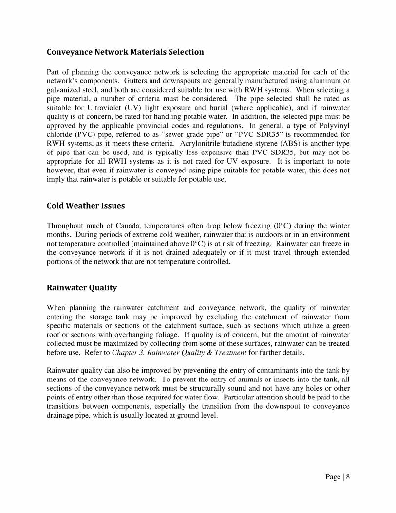
Conveyance Network Materials Selection
Part of planning the conveyance network is selecting the appropriate material for each of the network‘s components. Gutters and downspouts are generally manufactured using aluminum or galvanized steel, and both are considered suitable for use with RWH systems. When selecting a pipe material, a number of criteria must be considered. The pipe selected shall be rated as suitable for Ultraviolet (UV) light exposure and burial (where applicable), and if rainwater quality is of concern, be rated for handling potable water. In addition, the selected pipe must be approved by the applicable provincial codes and regulations. In general, a type of Polyvinyl chloride (PVC) pipe, referred to as ―sewer grade pipe‖ or ―PVC SDR35‖ is recommended for RWH systems, as it meets these criteria. Acrylonitrile butadiene styrene (ABS) is another type of pipe that can be used, and is typically less expensive than PVC SDR35, but may not be appropriate for all RWH systems as it is not rated for UV exposure. It is important to note however, that even if rainwater is conveyed using pipe suitable for potable water, this does not imply that rainwater is potable or suitable for potable use.
Cold Weather Issues
Throughout much of Canada, temperatures often drop below freezing (0°C) during the winter months. During periods of extreme cold weather, rainwater that is outdoors or in an environment not temperature controlled (maintained above 0°C) is at risk of freezing. Rainwater can freeze in the conveyance network if it is not drained adequately or if it must travel through extended portions of the network that are not temperature controlled.
Rainwater Quality
When planning the rainwater catchment and conveyance network, the quality of rainwater entering the storage tank may be improved by excluding the catchment of rainwater from specific materials or sections of the catchment surface, such as sections which utilize a green roof or sections with overhanging foliage. If quality is of concern, but the amount of rainwater collected must be maximized by collecting from some of these surfaces, rainwater can be treated before use. Refer to Chapter 3. Rainwater Quality & Treatment for further details. Rainwater quality can also be improved by preventing the entry of contaminants into the tank by means of the conveyance network. To prevent the entry of animals or insects into the tank, all sections of the conveyance network must be structurally sound and not have any holes or other points of entry other than those required for water flow. Particular attention should be paid to the transitions between components, especially the transition from the downspout to conveyance drainage pipe, which is usually located at ground level.

Page | 9
1.4 Design & Installation Guidelines
Design and installation guidelines:
Note: refer to Section 1.2 Applicable Codes, Standards, and Guidelines for the specific provisions that apply when the term ―in accordance with applicable provincial codes and regulations‖ is used.
1. When selecting the catchment(s) for collecting rainwater:
a. Only roof surfaces are recommended; b. Collection from green roofs is not recommended; c. Avoid sections of the roof with overhanging foliage, or trim where possible; d. If rainwater collected from the catchment surface must be of very high quality,
materials with NSF P151 certification can be selected. 2. To maximize the volume of rainwater collected by the RWH system:
a. The catchment surface should be as large as possible; b. If a roof catchment material is to be selected and installed in conjunction with the
RWH system, material with minimal collection losses, such as steel, should be selected (refer to Table A-1 for details);
c. Convey rainwater using appropriately sized and sloped components, including gutters, downspouts, and/or conveyance drainage piping; and
d. Where possible, multiple roof catchments can be connected to a central or ‗communal‘ rainwater storage tank.
3. Gutters and downspouts: a. Gutter and downspout material:
i. Aluminum or galvanized steel are recommended, ii. Copper, wood, vinyl, and plastic gutter and downspout materials are not
recommended, iii. If rainwater conveyed through gutters and downspouts must be of very
high quality, materials with NSF P151 certification can be selected. b. Gutter slope:
i. Where possible, slope gutters in the direction of the location of the rainwater storage tank,
ii. Ensure a minimum slope of 0.5-2% (the greater the slope the better) is maintained throughout the gutter length.
c. Gutter size: i. In general, 125 mm [5 in.] K-style gutter is commonly used and should be
suitable for most typical residential roof drainage areas and gutter lengths; ii. To determine the size of gutter required for a given roof drainage area:
1. Consult the applicable provincial codes and regulations pertaining to the design rainfall intensity for the site location,
2. Calculate the area of roof draining into the gutter:
Equation 1-1
Page | 10
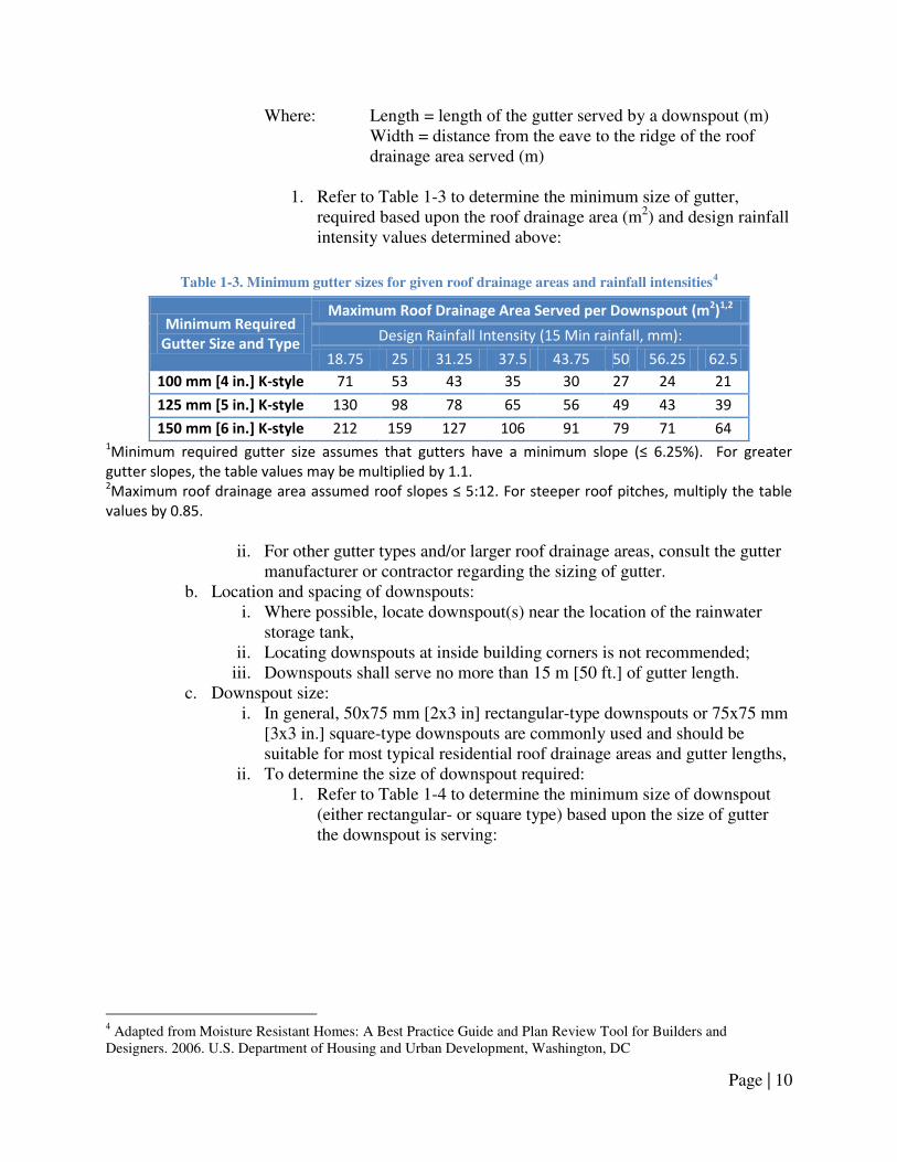
Where: Length = length of the gutter served by a downspout (m) Width = distance from the eave to the ridge of the roof drainage area served (m)
1. Refer to Table 1-3 to determine the minimum size of gutter,
required based upon the roof drainage area (m2) and design rainfall intensity values determined above:
Table 1-3. Minimum gutter sizes for given roof drainage areas and rainfall intensities4
Minimum Required Gutter Size and Type
Maximum Roof Drainage Area Served per Downspout (m2)1,2
Design Rainfall Intensity (15 Min rainfall, mm):
18.75 25 31.25 37.5 43.75 50 56.25 62.5
100 mm [4 in.] K-style 71 53 43 35 30 27 24 21
125 mm [5 in.] K-style 130 98 78 65 56 49 43 39
150 mm [6 in.] K-style 212 159 127 106 91 79 71 64 1Mi i u e ui ed gutte size assu es that gutte s ha e a i i u slope ≤ . % . Fo g eate gutter slopes, the table values may be multiplied by 1.1. 2Ma i u oof d ai age a ea assu ed oof slopes ≤ : . Fo steepe oof pit hes, ultipl the ta le values by 0.85.
ii. For other gutter types and/or larger roof drainage areas, consult the gutter
manufacturer or contractor regarding the sizing of gutter. b. Location and spacing of downspouts:
i. Where possible, locate downspout(s) near the location of the rainwater storage tank,
ii. Locating downspouts at inside building corners is not recommended; iii. Downspouts shall serve no more than 15 m [50 ft.] of gutter length.
c. Downspout size: i. In general, 50x75 mm [2x3 in] rectangular-type downspouts or 75x75 mm
[3x3 in.] square-type downspouts are commonly used and should be suitable for most typical residential roof drainage areas and gutter lengths,
ii. To determine the size of downspout required: 1. Refer to Table 1-4 to determine the minimum size of downspout
(either rectangular- or square type) based upon the size of gutter the downspout is serving:
4 Adapted from Moisture Resistant Homes: A Best Practice Guide and Plan Review Tool for Builders and Designers. 2006. U.S. Department of Housing and Urban Development, Washington, DC

Page | 11
Table 1-4. Minimum downspout sizes for given size of gutter5
Gutter Size and Type
Minimum Downspout Size ( mm [in] )
Rectangular type Square-type
100 mm [4 in.] K-style 50x75 [2x3 ] 75x75 [3x3]
125 mm [5 in.] K-style 50x75 [2x3] 75x75 [3x3]
150 mm [6 in.] K-style 75 x 100 [3x4] 100x100 [4x4]
iii. For other downspout types and/or larger gutter sizes, consult the
gutter/downspout manufacturer or contractor regarding the sizing of downspout.
d. Gutter and downspout installation: i. Gutters should be custom-fabricated and installed such that there are no
seams along the length of guttering, ii. Gutters shall be supported by hangers (hidden hanger or spike and ferrule)
that are spaced at a maximum of 450 mm [18 in.], iii. Downspout offsets should not exceed 3.0 m [10 ft.].
e. Refer to Appendix A for an example of sizing gutters and downspouts. 2. Catchment area:
a. In cases where an entire roof catchment or other catchment surface is utilized, catchment area can be determined using:
Equation 1-2
Where: Length = length of the catchment surface (m)
Width = width of the catchment surface (m)
b. In cases where sections of one roof catchment or multiple catchment surfaces are utilized, the catchment area can be determined by summing the multiple smaller areas.
3. Plan the layout of the conveyance network: a. For rainwater tanks located above ground:
i. Determine the location of the tank (refer to Chapter 2. Rainwater Storage
& Tank Sizing for guidance), ii. Route downspout(s) and/or conveyance drainage piping to the tank.
b. For rainwater tanks located below ground: i. Determine the location of the tank (refer to Chapter 2. Rainwater Storage
& Tank Sizing for guidance), ii. Plan route of conveyance drainage piping from the downspout(s) to the
tank,
5 Adapted from Moisture Resistant Homes: A Best Practice Guide and Plan Review Tool for Builders and Designers. 2006. U.S. Department of Housing and Urban Development, Washington, DC

Page | 12
iii. Ensure that there are no buried service lines (gas, electricity, water, stormwater, wastewater, phone, or cable lines) in the area where digging will take place to accommodate the buried conveyance drainage pipes by contacting the municipality and service providers,
iv. For additional guidance on planning the layout of conveyance drainage piping for below ground tanks, refer to Appendix A.
4. Conveyance drainage pipes: a. Pipe material:
i. PVC SDR35 pipe (recommended), or ABS pipe, where ii. Pipe selected must be approved by applicable provincial codes and
industry standards (CSA, ASTM, etc.). b. Pipe size and slope:
i. Ensure a minimum slope of 0.5-2% (the greater the slope the better) is maintained throughout the pipe length,
ii. Consult the applicable provincial codes and regulations pertaining to conveyance drainage pipe sizing, and
iii. For estimation purposes, consult Table A-1 and Table A-4 in Appendix A. c. Cleanouts:
i. Cleanouts are required on conveyance drainage pipes to facilitate cleaning of the conveyance drainage pipes,
ii. Consult the applicable provincial codes and regulations pertaining to size and spacing of cleanouts, manholes and location of cleanouts.
d. Tank connection: i. Rainwater conveyance drainage piping should enter the tank at a height no
lower than that of the overflow drainage piping, or ideally, at a height 50 mm [2 in.] above the bottom of the overflow drainage pipe(s) entering the tank.
5. Installation of conveyance drainage pipe: a. Above ground pipes shall be supported in accordance with applicable provincial
codes and regulations; b. Below ground pipes shall be located in a properly excavated space, be supported
and properly backfilled in accordance with applicable provincial codes and regulations;
c. Pipe freeze protection: i. Ensure that all buried pipes are located below the frost penetration depth.
Consult local building authorities regarding regulations or ‗rules of thumb‘ for frost penetration depths. For estimation purposes, refer to Appendix A,
ii. Provide insulation or heat tracing for pipes buried above the frost penetration depth or exposed above grade (refer to Appendix A for details regarding pipe insulation).
d. Underground non-metallic pipes should be installed with ‗tracer tape‘ (also referred to as ‗tracer wire‘) at a height of 300 mm [12 in.] above the pipe for the purpose of locating as-installed piping.
e. Consult the pipe manufacturer‘s installation instructions regarding recommended pipe bedding, support and backfilling procedures.

Page | 13
6. Tank frost protection: a. Storage tanks located above ground at risk for freezing shall be protected by:
i. A conveyance network bypass, where sections of downspout and/or pipe upstream of the tank shall be capable of being disconnected and/or re-routed to divert rainwater/snowmelt from entry into the tank during winter months,
ii. A drain valve located at the bottom of the storage tank. 7. Ensure that there are no means of entry for small animals or insects into the rainwater
storage tank from the conveyance network by: a. Properly installing all sections of the conveyance network, such that they do not
have any holes or other points of entry other than those required for water flow; and
b. Installing downspout-to-pipe transition fittings. 8. Install pre-storage treatment devices as required (refer to Chapter 3. Rainwater Quality &
Treatment for details).

Page | 14
1.5 Management Guidelines
1. The catchment surface should be inspected once every six months, to:
a. Identify any sources of contamination, including accumulated dirt and debris, presence of overhanging tree branches or other foliage, and/or signs of animal activity (i.e., bird droppings); and
b. If contaminants are present, these should be removed by cleaning the catchment surface by garden hose or sweeping, and if applicable trimming overhanging tree branches/foliage.
2. The gutters and downspouts should be inspected once every six months, to: a. Remove any dirt and debris that have accumulated; and b. Repair and/or replace damaged components to ensure proper rainwater flow and
prevent entry of birds, rodents or insects into the RWH system. 3. During periods of cold weather, the conveyance network should be inspected periodically
for ice build-up: a. Inspect the components of the conveyance network that are easily accessible (roof
inspection not recommended) for the presence of ice, and if present, monitor over time to determine if the ice is accumulating in the network;
b. For buried pipelines, ice build-up may be identified by poor performance of the RWH system (low volumes of stored rainwater even during frequent freeze-thaw periods) and/or by rainwater backing up the preceding sections of the network.
4. If ice is accumulating in sections of the conveyance network, and if it poses a risk of blocking and/or causing damage to the network, the following steps are recommended:
a. Winterize the conveyance network through some, or all, of the following: i. Install a heating system to maintain air temperatures above 0°C if a large
portion of the conveyance network is located in cold indoor environments like garages,
ii. Install heat trace wire around gutters and/or downspouts, iii. Excavate the conveyance drainage pipes and install rigid Styrofoam
insulation or heat tracing. b. Alternatively, the RWH system can be decommissioned during the winter months
(refer to Section 2.5 of Chapter 2. Rainwater Storage & Tank Sizing for details). 5. While inspecting, cleaning, or repairing the catchment surface and parts of the
conveyance network, follow all necessary safety precautions.
Page | 15
Chapter 2. Rainwater Storage & Tank Sizing
2.1 Introduction
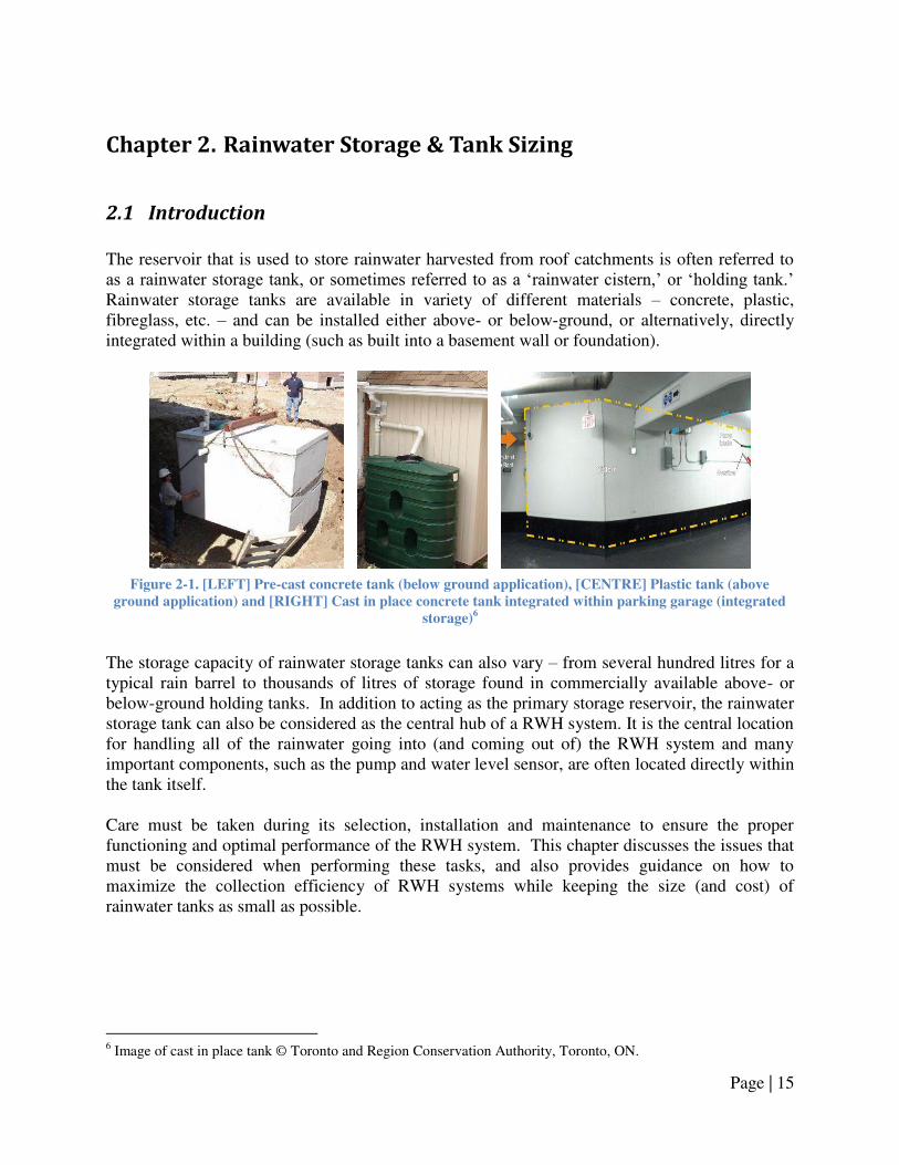
The reservoir that is used to store rainwater harvested from roof catchments is often referred to as a rainwater storage tank, or sometimes referred to as a ‗rainwater cistern,‘ or ‗holding tank.‘ Rainwater storage tanks are available in variety of different materials – concrete, plastic, fibreglass, etc. – and can be installed either above- or below-ground, or alternatively, directly integrated within a building (such as built into a basement wall or foundation).
Figure 2-1. [LEFT] Pre-cast concrete tank (below ground application), [CENTRE] Plastic tank (above
ground application) and [RIGHT] Cast in place concrete tank integrated within parking garage (integrated
storage)6
The storage capacity of rainwater storage tanks can also vary – from several hundred litres for a typical rain barrel to thousands of litres of storage found in commercially available above- or below-ground holding tanks. In addition to acting as the primary storage reservoir, the rainwater storage tank can also be considered as the central hub of a RWH system. It is the central location for handling all of the rainwater going into (and coming out of) the RWH system and many important components, such as the pump and water level sensor, are often located directly within the tank itself. Care must be taken during its selection, installation and maintenance to ensure the proper functioning and optimal performance of the RWH system. This chapter discusses the issues that must be considered when performing these tasks, and also provides guidance on how to maximize the collection efficiency of RWH systems while keeping the size (and cost) of rainwater tanks as small as possible.
6 Image of cast in place tank © Toronto and Region Conservation Authority, Toronto, ON.

Page | 16
2.2 Applicable Codes, Standards, and Guidelines
Table 2-1 references specific codes and standards that are applicable to rainwater storage tanks.
Table 2-1. Applicable standards, codes and guidelines for rainwater storage tanks
Applicable Codes,
Standards, and
Guidelines
Selected Provisions &
Design and Installation Implications
Alberta Occupational
Health & Safety Code
(2009)
Part 5 Confined Spaces
Where entry into a rainwater tank is needed to install components,
precautions outlined in Alberta OHS Code 2009 Part 5 Confined Spaces must
be followed.
Alberta Private Sewage
Systems Standard of
Practice
(2009)
2.5.2.7. Piping Connections to Tank
4.2.1.3. Infiltration/Exfiltration Prevention
4.2.1.4. Insulation of Tank
4.2.2.1. Separation Distances
4.2.2.3. Septic Tank Manhole Access Not Buried
4.2.2.4. Access Opening Lid/Cover
4.2.2.6. Insulation of Tank
4.2.2.7. Base for Septic Tank
Article 2.5.2.7. provides specifications for the connection of piping to tanks.
Other aspects of septic tank design, including: minimum clearances of tanks
from wells, property lines, etc., and proper installation and insulation for
frost protection (Articles 4.2.1.4. and 4.2.2.6.). Other Articles pertain to
access manholes and tank bedding.
Note: These specifications refer to septic tanks, but provide guidance on the
design and installation requirements for rainwater storage tanks. Their use
is recommended.
CSA Standard B128.1
(2006)
7.0 Storage Tanks
Provides specifications for the design and installation of rainwater storage
tanks, including: access openings, piping connections, overflow, drainage
and venting.
NSF/ANSI Standard 61
(2008)
Selection of a plastic tank with NSF/ANSI Standard 61 certification is will not
impart unsafe levels of contaminants in drinking water. Recommended
where high quality rainwater is needed for the intended use.
Mandatory Documents Supplementary Documents

Page | 17
2.3 Issues for Consideration
General
As the central hub for RWH systems, rainwater storage tanks are directly connected to a number of pipes and also house some components internally. These components may include some, or all, of the following items shown in Figure 2-2.
Figure 2-2. Rainwater storage tank schematic
Tank Location
The optimum location of a tank on a given site depends upon the required fall for the gravity flow conveyance network (as discussed in Chapter 1: Rainwater Catchment & Conveyance), as well as a broader range of issues, including:
1. Placement of tank – above- or below-ground, or integrated within building, 2. Desired/required rainwater storage tank capacity, 3. Regional climate – freezing issues, 4. Site conditions – site grading, accessibility, and space availability, 5. Proximity to the following:
a. Catchment area, b. Overflow discharge location, c. Control components of pump and pressure system, d. Other site services (i.e.,. gas, electricity, water, stormwater, wastewater, phone, or
cable lines).
LOW WATER
LEVEL
HIGH WATER
LEVEL
ACCESS RISER (BELOW GROUND TANKS)
OR
ACESS HATCH (ABOVE GROUND TANKS & INTEGRATED STORAGE)
6. PUMP
OR
PUMP INTAKE
5. RAINWATER OVERFLOW DRAINAGE PIPING
RAINWATER STORAGE TANK CAPACITY
4. RAINWATER PRESSURE PIPING (TO NON-POTABLE FIXTURES)
1. RAINWATER CONVEYANCE DRAINAGE PIPING
2. TOP-UP DRAINAGE PIPING
3. ELECTRICAL
SUPPLY CONDUIT
7.WATER LEVEL SENSOR (FLOAT SWITCHES SHOWN)
8. ELECTRICAL WIRING

Page | 18
Following consideration of each of these issues, it is likely that trade-offs must be made – for instance, the optimum tank storage capacity may be too large to be accommodated at the site, or the optimum location for the tank may be in an area that is difficult to access. Some guidance with respect to these issues is provided in the following sections.
Tank Placement
Table 2-2 discusses some of the advantages and disadvantages associated with the different placement options with regards to rainwater storage.
Table 2-2. Advantages and disadvantages of different tank locations
Tank Placement Advantages Disadvantages
Above-ground Do t ha e site e a atio costs associated with below-
ground storage
Rainwater may freeze in tank
unless located in
temperature controlled
environment
Below-ground storage Storage tank can be placed
below frost penetration
depth, permitting year-
round operation
Does not take up yard space
Location must be free of
buried service lines and
accessible by excavation
machinery
Excavation requires
additional site work which
increases cost of RWH
system
Integrated storage Little or no excavation cost
Storage tank capacity can be
customized for each site
Permits year-round
operation
Engineers must design
storage reservoir such that it
is structurally sound and
does not leak into the
building
Tank Capacity
In general, the larger the tank, the greater the volume of rainwater that can be collected and stored during rainfall events (collection efficiency). However, this is true only up to a certain point – after which other factors, such as local rainfall patterns, roof catchment area and rainwater demand, will limit the amount of rainfall that can be collected and utilized by the system. Thus, for a RWH system with a given roof catchment area, rainwater demands and local rainfall patterns, the storage capacity of the tank can be described as either:

Page | 19
1. Too small –Much of the collected rainwater overflows during rainfall events. Significant improvements in collection efficiency can be achieved from minor increments in storage volume.
2. Optimum range – Rainwater tanks in this range provide the best balance between collection efficiency of the RWH system and minimizing its size and cost.
3. Too large – Rainwater tanks in this range rarely fill to capacity. A smaller tank can be utilized without a significant drop in the collection efficiency of the RWH system. An over-sized rainwater storage tank, however, may be desirable if stormwater management is a strong driver for installing a RWH system.
To determine the appropriate rainwater storage tank capacity, two methods are available: Rainwater Harvesting Design Tool – This is a Microsoft Excel-based program that can be used to determine the optimal storage tank capacity given site-specific details including city, catchment area and material, and rainwater demands. For further details regarding this companion to the Alberta Guidelines for Residential Rainwater Harvesting Systems, refer to Appendix B. Rainwater Storage Tank Sizing Tables – Tables of optimal rainwater tank capacities have been generated using the Rainwater Harvesting Design Tool for the city of Edmonton, given a variety of roof catchment areas and rainwater demands. This table is provided in Appendix B. Note that when selecting a tank size, consideration must be given to the unused volume at the bottom and top of the tank (sometimes referred to as ‗dead space‘), which reduces the effective storage volume. Refer to Chapter 4. Make-up Water System and Backflow Prevention and Chapter 5. Pump and Pressurized Distribution System for information regarding dead space at the bottom of the tank.
Cold Weather Issues
Throughout much of Canada, temperatures often drop below freezing (0°C) during the winter months. Rainwater stored outdoors or in an environment not temperature controlled (maintained above 0°C) is at risk of freezing, either in the storage tank itself, in the pump pressure piping, or both. Water freezing in either location may cause short term blockages and service disruptions, or in the long term, the RHW system may become damaged through the expansion of ice in the system. To minimize these risks, the following options are available:
1. Winter decommissioning – If an outdoor above-ground tank is used to store rainwater (or other setup in a non-temperature controlled setting), the tank, pump and pressurized lines shall be drained of all rainwater prior to the onset of cold weather and use of the system shall be discontinued during the winter months.
2. Winterize RWH system – A RWH system can be utilized year-round in cold climates provided the tank is:
a. Located in a temperature-controlled environment such as a heated garage or basement in the case of above-ground or integrated rainwater storage; or

Page | 20
b. Located in a below-ground tank that is buried below the local frost penetration depth.
The first option is generally the simplest and least costly system to design and install. These benefits, however, are largely offset by the significant reduction in rainwater that can be collected and used throughout a given year, as well as by the potential damage to system components if decommissioning occurs too late or not at all. The second option, to winterize the system, is more complicated and more costly, however it is preferred since it enables the RWH system to operate throughout the entire year and ensures system components are protected from frost damage.
Tank Material
In Canada, materials such as concrete, plastic, and fiberglass are commonly used in the construction of storage reservoirs. The selection of one of these materials for a rainwater storage tank will largely depend upon local availability, as well as on cost, tank placement (above- or below-ground or integrated), storage requirements, site accessibility, and/or engineering specifications. In recent installations, above-ground tanks are often plastic while integrated tanks are usually cast-in-place concrete. Below-ground tanks are usually pre-cast concrete or plastic. In general, greater economies of scale are seen for concrete tanks than for plastic tanks, making concrete a more desirable material for very large systems. Engineering specifications such as maximum rated burial depth or minimum required water level vary for different tank materials and designs. Installation and operational specifications can be sought from manufacturers. Another consideration is the potential for chemicals to leach from the tank into the stored rainwater; however, this is primarily a concern if rainwater must be of very high quality for one or more of the connected rainwater fixtures.

Page | 21
2.4 Design & Installation Guidelines
Design and installation guidelines:
Note: refer to Section 2.2 Applicable Codes, Standards, and Guidelines for the specific provisions that apply when the term ―in accordance with applicable provincial codes and regulations‖ is used.
1. Determine the rainwater storage tank capacity:
a. If the rainwater storage tank will be used for stormwater retention and/or as part of a stormwater management system, the tank shall be sized as required by local authorities (refer to Chapter 6. Overflow Provisions & Stormwater Management for details);
b. For storage tanks used for rainwater harvesting purposes: i. Use the Rainwater Harvesting System Design Tool (refer to Appendix B
for instructions on accessing the Design Tool), or ii. Use the method provided in the Rainwater Storage Tank Sizing Table
section of Appendix B. c. If sizing the tank without reference to the Design Tool or Tank Sizing Table,
consider: i. The unused volume (typically referred to as the ‗dead space‘) when
selecting tank size. If unknown, assume 20% of tank capacity will be dead space,
ii. The collection losses from pre-storage treatment devices (refer to Chapter
3. Rainwater Quality & Treatment for details). 2. Determine the type of material utilized for the rainwater tank, based on:
a. Placement (above- or below-ground, or integrated storage); b. Storage volume requirements; c. Engineering specifications (see Section 2.2 Applicable Codes, Standards, and
Guidelines for applicable standards and consult with manufacturers for further specifications); and
d. Connected rainwater fixtures and desired quality. (See Section 3.2 Applicable
Codes, Standards, and Guidelines for applicable standards). 3. Determine the location of the rainwater storage tank:
a. For all rainwater storage tank locations: i. Ensure the location allows for:
1. Proper drainage of rainwater through the conveyance network (refer to Chapter 1. Rainwater Catchment & Conveyance for details),
2. Proper drainage of make-up water through top-up drainage piping (refer to Chapter 4. Make-up Water System and Backflow
Prevention for details), 3. Proper drainage of rainwater from the storage tank to an
appropriate stormwater discharge location (refer to Chapter 6.
Overflow Provisions & Stormwater Management for details).

Page | 22
b. For below ground storage tanks: i. Identify the area(s) where the tank can be located:
1. Ensure the location is free from buried service lines. Contact service providers to determine the location of buried service lines (gas, electricity, water, stormwater, wastewater, phone, or cable lines),
2. Ensure the location is permitted by applicable provincial codes and regulations based upon the minimum clearance requirements for buried tanks,
3. Ensure the location is accessible for excavation equipment and the tank delivery vehicle. Consult the excavation contractor and tank supplier for exact requirements.
ii. Tank freeze protection: 1. Locate the tank such that the high water level in the tank is at a
depth below the frost penetration depth (consult the tank manufacturer regarding the rated burial depth of the tank),
2. Consult applicable provincial codes and regulations and/or local building authorities to determine local frost penetration depth (refer to Appendix A for an estimation of frost depth),
3. If the tank cannot be placed below frost depth, insulate with rigid Styrofoam, installed on the tank roof and extended out beyond the tank walls (refer to Appendix A for guidelines regarding thickness of foam insulation).
c. For above ground storage tanks: i. Identify the area(s) where the tank can be located:
1. Ensure the location is permitted by applicable provincial codes and regulations and municipal zoning bylaws. Consult local building authorities for details,
2. Ensure the location has sufficient space for access above and around the tanks for inspection and maintenance.
ii. Tank freeze protection: 1. If the tank is not located in a temperature-controlled environment
and is at risk for freezing, winterizing or decommissioning must be performed in accordance with the guidelines below.
d. For rainwater storage tanks located within a building and/or integrated within a building:
i. Identify the area(s) where the tank can be located: 1. Ensure the location is permitted by applicable provincial codes and
regulations and municipal zoning bylaws. Consult local building authorities for details,
2. Ensure the location has sufficient space for the required storage volume,
3. Ensure the location has sufficient space for access above and around the tanks for inspection and maintenance,

Page | 23
4. Ensure provisions (such as floor drains and/or sump pump) are in place to handle potential leaks and overflows from the storage tank,
5. Consult a structural engineer regarding the design and location of all integrated tanks, as well as indoor tanks located anywhere other than the basement or garage.
ii. Tank freezing protection: 1. Locate the tank in a temperature-controlled environment such as a
heated garage or basement to prevent tank freezing, 2. If the tank is not located in a temperature-controlled environment
and is at risk for freezing, winterizing or decommissioning must be performed in accordance with the guidelines below.
4. Tank frost protection: a. If the tank is not located in a temperature-controlled environment and is at risk for
freezing, winterizing or decommissioning must be performed: i. Winterizing:
1. Provide a heating system to maintain air temperatures above 0°C (if tank is located indoors),
2. Provide a water heating system directly inside the rainwater tank, 3. Insulate the rainwater storage tank.
ii. Decommissioning: 1. Prior to the onset of freezing temperatures, the rainwater stored in
the rainwater tank must be drained, 2. Provisions shall be made to prevent the accumulation of rainwater
and/or snowmelt into the tank during winter months by means of a tank bypass or tank drain valve (refer to Section 1.4 Design &
Installation Guidelines for further details). 5. Tank access and openings 7:
a. Tanks shall be provided with an access opening; b. Access openings shall be a minimum of 450 mm [18 in.] to facilitate installation,
inspection and maintenance of components within the rainwater storage tank; c. Access openings shall have drip-proof, non-corrosive covers; d. Openings that are larger than 100 mm [4 in.] shall have lockable covers; e. Consult applicable provincial codes and standards regarding tank access and
openings. 6. Tank venting:
a. For below ground rainwater storage tanks: i. In general, venting of the tank through the rainwater conveyance drainage
piping and overflow drainage piping connected to the tank(s) is considered to be sufficient for typical single family residential dwelling,
ii. For other dwellings, or in cases where venting by means of conveyance drainage piping and overflow drainage piping connections is considered insufficient, a vent shall be installed on each tank, where:
7 Adapted from CAN/CSA-B128.1-06 Design and installation of non-potable water systems. 2006. CSA International, Mississauga, ON. Refer to CSA B128.1 for further details.

Page | 24
1. The vent pipe shall extend from the top of tank to a minimum height of 150 mm [6 in.] above grade,
2. The vent pipe shall be of a sufficient size to permit the flow of air while the tank is filling, and shall be no less than 75 mm [3 in.] in size,
3. Vent shall terminate in a gooseneck fitting with a screen to prevent the entry of birds, rodents and insects.
b. For rainwater storage tanks located indoors and/or integrated within buildings: i. Rooms containing open tanks shall be vented to the outside of the building
to prevent the accumulation of humidity or noxious gases. 7. Installation of storage tanks:
a. Below ground tanks shall be placed in a properly excavated space, be supported on a tank bedding and be properly backfilled in accordance with applicable codes and standards;
b. Integrated storage tanks must be constructed and/or installed in accordance with the designer‘s instructions and good engineering practice;
c. Consult the tank manufacturer‘s installation instructions regarding recommended tank bedding, support and backfilling procedures;
d. Connect the rainwater conveyance drainage pipe(s), overflow drainage pipe(s), rainwater pressure pipe(s) and electrical conduit(s) to the tank, ensuring that the connections are properly sealed and watertight.
8. Installation of components within the rainwater storage tank: a. Components installed within the tank typically include:
i. A pump or pump intake (refer to Chapter 5. Pump and Pressurized
Distribution System for details), ii. Water level sensors and/or other types of control equipment,
iii. Electrical wiring for the pump and control equipment (refer to Chapter 4.
Make-up Water System and Backflow Prevention for details). b. Entry into the rainwater storage tank, for the purposes of installing components
within the tank is not recommended; c. If entry inside the rainwater storage tank is required, it shall be performed in
accordance with Part 5 Confined Spaces of the Alberta Occupational Health & Safety Code due to the significant dangers involved when working within a confined space;
d. To reduce and/or eliminate the need to perform work inside the storage tank: i. Wherever possible, install internal components using the access port,
without entering the tank, or ii. Have RWH components installed by tank manufacturer, using personnel
trained in confined spaces. e. Install components such that they are accessible for inspection and maintenance,
without entry into tank; f. Components installed in the tank should be suited for a wet environment.
Page | 25
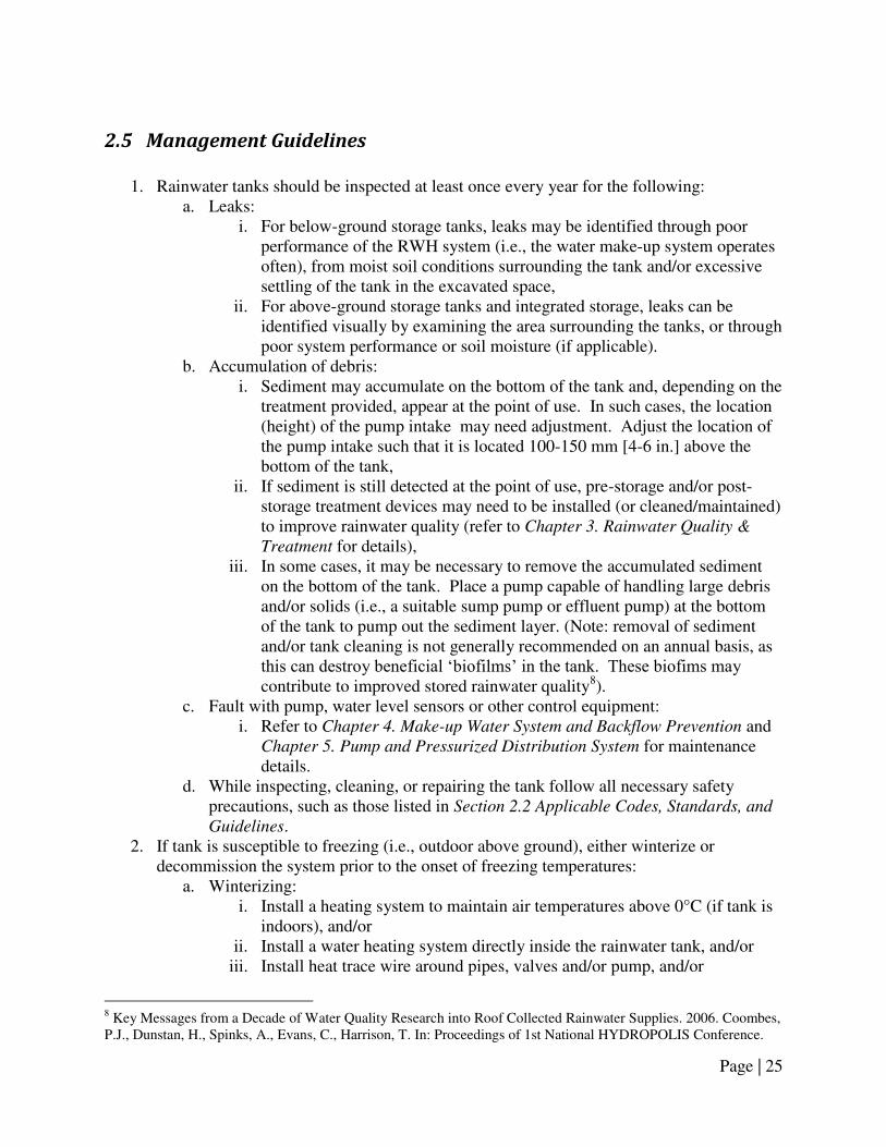
2.5 Management Guidelines
1. Rainwater tanks should be inspected at least once every year for the following:
a. Leaks: i. For below-ground storage tanks, leaks may be identified through poor
performance of the RWH system (i.e., the water make-up system operates often), from moist soil conditions surrounding the tank and/or excessive settling of the tank in the excavated space,
ii. For above-ground storage tanks and integrated storage, leaks can be identified visually by examining the area surrounding the tanks, or through poor system performance or soil moisture (if applicable).
b. Accumulation of debris: i. Sediment may accumulate on the bottom of the tank and, depending on the
treatment provided, appear at the point of use. In such cases, the location (height) of the pump intake may need adjustment. Adjust the location of the pump intake such that it is located 100-150 mm [4-6 in.] above the bottom of the tank,
ii. If sediment is still detected at the point of use, pre-storage and/or post-storage treatment devices may need to be installed (or cleaned/maintained) to improve rainwater quality (refer to Chapter 3. Rainwater Quality &
Treatment for details), iii. In some cases, it may be necessary to remove the accumulated sediment
on the bottom of the tank. Place a pump capable of handling large debris and/or solids (i.e., a suitable sump pump or effluent pump) at the bottom of the tank to pump out the sediment layer. (Note: removal of sediment and/or tank cleaning is not generally recommended on an annual basis, as this can destroy beneficial ‗biofilms‘ in the tank. These biofims may contribute to improved stored rainwater quality8).
c. Fault with pump, water level sensors or other control equipment: i. Refer to Chapter 4. Make-up Water System and Backflow Prevention and
Chapter 5. Pump and Pressurized Distribution System for maintenance details.
d. While inspecting, cleaning, or repairing the tank follow all necessary safety precautions, such as those listed in Section 2.2 Applicable Codes, Standards, and
Guidelines. 2. If tank is susceptible to freezing (i.e., outdoor above ground), either winterize or
decommission the system prior to the onset of freezing temperatures: a. Winterizing:
i. Install a heating system to maintain air temperatures above 0°C (if tank is indoors), and/or
ii. Install a water heating system directly inside the rainwater tank, and/or iii. Install heat trace wire around pipes, valves and/or pump, and/or
8 Key Messages from a Decade of Water Quality Research into Roof Collected Rainwater Supplies. 2006. Coombes, P.J., Dunstan, H., Spinks, A., Evans, C., Harrison, T. In: Proceedings of 1st National HYDROPOLIS Conference.

Page | 26
iv. Install insulation on the rainwater tank, around pipes, valves and/or pump. b. Decommissioning:
i. Drain all of the rainwater stored in the tank and the rainwater pressure piping,
ii. Shut off the water supply to the water make-up system (if present) to prevent the tank from refilling,
iii. Disconnect electrical supply to the pump and control equipment, iv. Disconnect downspouts from the conveyance network and have them
discharge to grade or other suitable location, and v. Disconnect fixtures from rainwater supply and connect to the potable
water system.

Page | 27
Chapter 3. Rainwater Quality & Treatment
3.1 Introduction
As precipitation falling from the sky, rainwater is naturally of very high quality. Once this precipitation reaches the earth, however, rainwater comes into contact with a variety of surfaces – grasses and landscapes, bodies of water, and anthropogenic surfaces such as roofs and parking lots – that can impart contaminants to the rainwater runoff. Contaminants can also be introduced into rainwater from environmental conditions such as the presence of air pollutants from industry and major roadways, and from plants or animal activity.
Figure 3-1. Factors that can affect rainwater quality
The presence of these contaminants can affect the physical, chemical and/or biological properties of water, and if present in sufficient quantities, they can affect the aesthetic quality of water (its colour, taste, and odour) and/or produce negative human health impacts from its use. For these reasons, rainwater quality (a measure of its physical, chemical and biological characteristics) is one of the key factors that determine its suitability for a particular use. This chapter discusses the factors that can affect rainwater quality and provides suggestions on how these risk factors can be mitigated through the appropriate design and installation of rainwater harvesting systems and through the application of rainwater treatment.
Rainwater Quality
Environment
Catchment Surface
Pre-storage Treatment
Rainwater Storage
Tank
Post-storage Treatment

Page | 28
3.2 Applicable Codes, Standards, and Guidelines
Table 3-1 references specific codes and standards that are applicable to the quality of harvested rainwater and required treatment.
Table 3-1. Applicable standards, codes and guidelines for rainwater quality and treatment
Applicable Codes,
Standards, and
Guidelines
Selected Provisions &
Design and Installation Implications
N/A No rainwater and/or non-potable water quality standards or treatment
requirements are specified by the ABC (2006 ed.) or NPC (2005 ed.).
Canadian Guidelines for
Domestic Reclaimed
Water for Use in Toilet
and Urinal Flushing
(Draft, 2007)
Sets out water quality guidelines, water quality testing protocols and
management frameworks for domestic reclaimed water use in toilets.
Note: No quality standard has been set in Alberta for rainwater use. Any
system supplying rainwater to a use that has potential direct contact and
serves other than a single family dwelling should meet a quality as set out in
this draft guideline.
CSA Standard B128.1
(2006)
8.0 Treatment
Specifies that water supplied by a RWH system must be treated to meet the
water quality standards specified by public health or other regulatory
authorities.
NSF Protocol P151
(1995)
Selection of roofing materials, coatings, paints, and gutters with NSF P151
certification will not impart levels of contaminants greater than those
spe ified i the U.S. EPA s D i ki g Wate Regulatio s. Re o e ded where high quality rainwater is needed for the intended use.
Note: Not legally binding unless adopted in future editions of the ABC or
NPC.
NSF/ANSI Standard 61
(2008)
Selection of a plastic tank with NSF/ANSI Standard 61 certification is will not
impart unsafe levels of contaminants in drinking water. Recommended
where high quality rainwater is needed for the intended use.
Note: Not legally binding unless adopted in future editions of the ABC or
NPC.
Mandatory Documents Supplementary Documents
Page | 29
3.3 Issues for Consideration
Rainwater Quality & Treatment Guidelines
There are currently no water quality guidelines that pertain specifically to the use of rainwater, either nationally or in the Province of Alberta. The Canadian Guidelines for Domestic
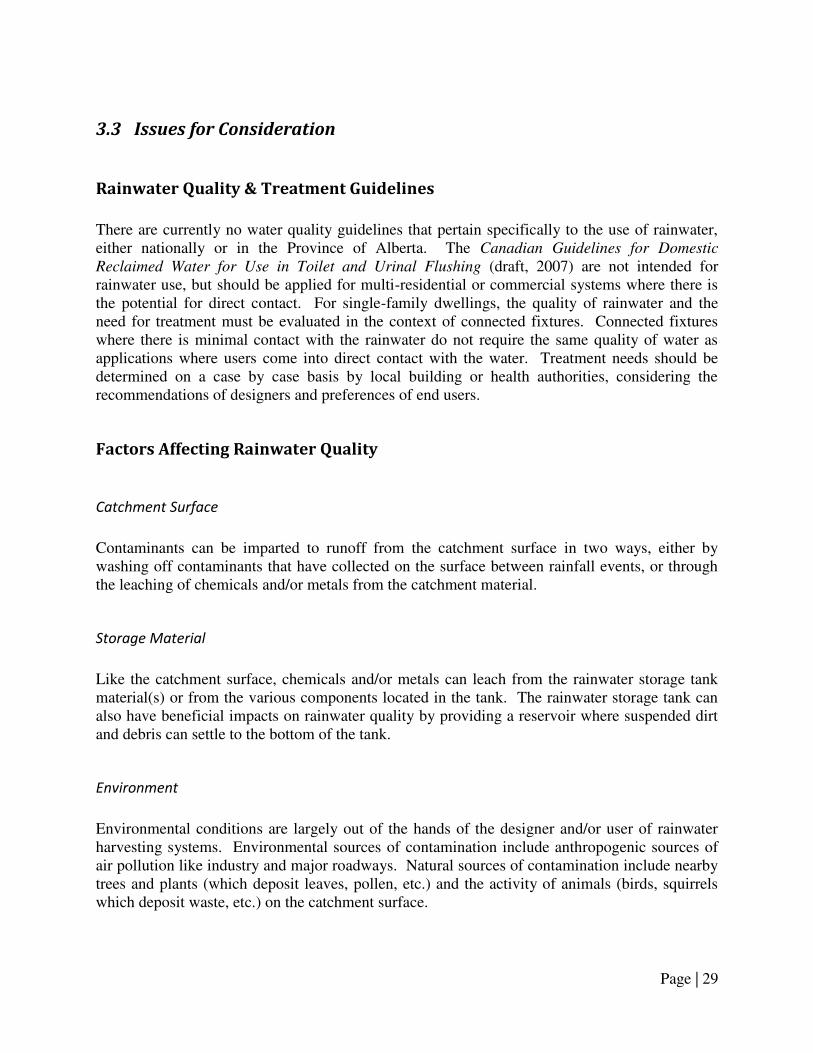
Reclaimed Water for Use in Toilet and Urinal Flushing (draft, 2007) are not intended for rainwater use, but should be applied for multi-residential or commercial systems where there is the potential for direct contact. For single-family dwellings, the quality of rainwater and the need for treatment must be evaluated in the context of connected fixtures. Connected fixtures where there is minimal contact with the rainwater do not require the same quality of water as applications where users come into direct contact with the water. Treatment needs should be determined on a case by case basis by local building or health authorities, considering the recommendations of designers and preferences of end users.
Factors Affecting Rainwater Quality
Catchment Surface
Contaminants can be imparted to runoff from the catchment surface in two ways, either by washing off contaminants that have collected on the surface between rainfall events, or through the leaching of chemicals and/or metals from the catchment material.
Storage Material
Like the catchment surface, chemicals and/or metals can leach from the rainwater storage tank material(s) or from the various components located in the tank. The rainwater storage tank can also have beneficial impacts on rainwater quality by providing a reservoir where suspended dirt and debris can settle to the bottom of the tank.
Environment
Environmental conditions are largely out of the hands of the designer and/or user of rainwater harvesting systems. Environmental sources of contamination include anthropogenic sources of air pollution like industry and major roadways. Natural sources of contamination include nearby trees and plants (which deposit leaves, pollen, etc.) and the activity of animals (birds, squirrels which deposit waste, etc.) on the catchment surface.

Page | 30
Rainwater Overflows
Contaminants can also be introduced into the rainwater storage tank through the overflow-handling method utilized by the rainwater harvesting system (see Chapter 6. Overflow
Provisions & Stormwater Management for details). If overflows are directed to a municipal storm sewer or an on-site soakaway pit, there is the potential during intense rainfall events for these systems to backflow into the tank, contaminating it with poor quality water. These overflow-handling systems must be designed properly, and preventative measures put in place, to minimize the possibility of storage tank contamination.
Treatment Options
Treatment can be applied to improve rainwater quality and can take place:
1. Before it is stored in the rainwater storage tank (pre-storage treatment), and/or 2. After it is stored in the rainwater storage tank (post-storage treatment)
Pre-storage treatment devices must be incorporated as part of the conveyance network and rely on gravity flow to facilitate the treatment process. Alternatively, post-storage treatment devices tend to be more rigorous than pre-storage treatment and often require pressurized flow and/or electricity to aid in the treatment process. The advantages and disadvantages associated with these treatment approaches are summarized in Table 3-2.
Table 3-2. Comparison of advantages and disadvantages associated with Pre- and Post-storage treatment
Treatment
Location Advantages Disadvantages
Pre-storage
treatment
Simple in design; operates using
gravity flow (no electricity or high
pressure requirements)
Prevents large particles from
accumulating in the storage tank
Reduces requirements for post-
storage treatment devices (or can
preclude their use altogether)
Susceptible to freezing
Requires regular cleaning and
maintenance. Poorly-maintained
devices may prevent rainwater from
being conveyed to tank or may
permit untreated rainwater to enter
the tank
Multiple collection points may
require a number of localized pre-
treatment devices, increasing cost
Post-storage
treatment
Very high quality of water can be
achieved
Located inside building, so no
freezing risks
Can be used to treat more
complex quality issues (i.e., pine
needles in tank that create tannic
acids)
May require maintenance and
replacement of filters, chemicals, or
other materials
End quality depends on incoming
rainwater quality and maintenance of
pre-storage treatment devices
Generally more expensive than pre-
storage treatment

Page | 31
Pre-storage Treatment Devices
Although there are a variety of means of treating rainwater prior to storage, methods tend to use one of three techniques: first-flush diversion, filtration, or settling. First flush diversion involves diverting the first portion of runoff (collected from the catchment surface) away from the storage tank. One of the many means by which this diversion can take place is depicted in Figure 3-2. This technique improves stored rainwater quality by preventing the entry of the dirt and debris that collect on the catchment surface between rainfall events – the majority of which are contained in the first portion of runoff (first-flush).
Figure 3-2. Schematic indicating the operation of a first-flush diverter
The second method, filtration, involves screening out leaves and large debris from runoff, preventing their entry into the rainwater storage tank. Filtration can take place at or near the catchment surface in the form of screens placed over gutters (referred to as ―gutter guards‖) or screens placed over rain leaders on flat roofed buildings (common on commercial buildings). Filtration can also take place on downspouts, or be integrated into other parts of the conveyance network. Examples of commercial filtration devices are shown in Figure 3-3.
FIRST-FLUSH
CHAMBER
FIRST-FLUSH
EFFLUENT FROM SLOW DRIP
EMITTER
RAINWATER FROM ROOF
CATCHMENT
TREATED
RAINWATER TO
TANK
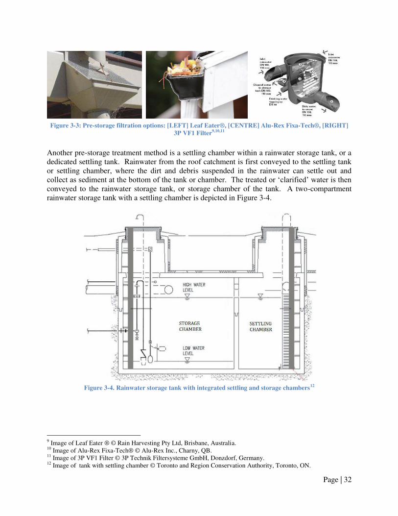
Page | 32
Figure 3-3: Pre-storage filtration options: [LEFT] Leaf Eater®, [CENTRE] Alu-Rex Fixa-Tech®, [RIGHT]
3P VF1 Filter9,10,11
Another pre-storage treatment method is a settling chamber within a rainwater storage tank, or a dedicated settling tank. Rainwater from the roof catchment is first conveyed to the settling tank or settling chamber, where the dirt and debris suspended in the rainwater can settle out and collect as sediment at the bottom of the tank or chamber. The treated or ‗clarified‘ water is then conveyed to the rainwater storage tank, or storage chamber of the tank. A two-compartment rainwater storage tank with a settling chamber is depicted in Figure 3-4.
Figure 3-4. Rainwater storage tank with integrated settling and storage chambers
12
9 Image of Leaf Eater ® © Rain Harvesting Pty Ltd, Brisbane, Australia. 10 Image of Alu-Rex Fixa-Tech® © Alu-Rex Inc., Charny, QB. 11 Image of 3P VF1 Filter © 3P Technik Filtersysteme GmbH, Donzdorf, Germany. 12 Image of tank with settling chamber © Toronto and Region Conservation Authority, Toronto, ON.

Page | 33
Post-storage Treatment Devices
Post-storage treatment includes filtration, disinfection, and/or treatment for aesthetic issues like colour, taste, or odour. Like pre-storage treatment, there are a number of different treatment devices available to perform these tasks. A description of these techniques, their applications and a list of available devices/options are provided in Table 3-3. A common form of post-storage treatment is 5 micron particle filtration, followed by and ultraviolet (UV) disinfection.
Table 3-3. Summary of post-storage treatment options
Treatment Method Details Treatment Devices/Options
Available1
Filtration
Filtration removes suspended particles
from water by passing it through a
permeable material.
Water quality issues targeted:
Turbidity
Total suspended solids
Particle filtration (i.e., bag/sock or
cartridge filter)
Slow sand filtration
Membrane filtration
Disinfection2
Disinfection removes or inactivates
microorganisms by chemical or
physical means.
Water quality issues targeted:
Microbiological contaminants
(viruses, bacteria and protozoa)
Ultraviolet (UV)
Chlorine
Ozonation
Slow sand filter
Membrane filtration
Thermal treatment
Aesthetic issue
treatment
Aesthetic issue treatment removes
constituents from water that
contribute towards colour, taste, or
odour issues.
Water quality issues targeted:
Hydrogen sulphide
Organic matter
Manganese
Iron
Activated carbon
Ozonation
Slow sand filter
Reverse Osmosis
Membrane filtration with
chemical addition
1 Other treatment options may be available.
2 All methods will require some level of on-line monitoring to ensure disinfection is reaching appropriate
levels.
Page | 34
Treatment Device Selection
When determining the treatment device(s) required for a rainwater harvesting system, the following questions should be considered:
1. What quality requirements do applicable provincial, territorial and/or national codes and regulations specify for the uses under consideration?
2. What applications will the rainwater be used for? 3. Can the rainwater harvesting system supply sufficient quantities of rainwater to meet the
desired uses? 4. Can treatment requirements be achieved through the proper design, installation and
maintenance of the rainwater harvesting system? 5. What are the personal preferences of those using the rainwater and those who are
managing the rainwater harvesting system? 6. What treatment devices are locally available? 7. Are there methods of segregating the rainwater usage in the house or building (i.e.,
supplying rainwater of varying qualities to different fixtures)? 8. What is the waste stream that is going to be generated through treatment? How will it be
disposed? 9. What are the capital, operations and maintenance costs associated with the treatment
device(s)? 10. Who will be responsible for the management of the rainwater harvesting system, and
treatment system specifically? (i.e., who will ensure that maintenance is performed, provide training to maintenance personnel, and pay for the replacement of filters or other components?)
Recommendations on how to address these questions and select the method of treatment are provided in Section 3.4 Design & Installation Guidelines.
Performance Issues with Treatment Devices
Losses
Like the roof catchment, pre-storage treatment devices typically reduce the collection efficiency of a rainwater harvesting system. These losses can be quantified using the same measures as were used for the catchment surface – an initial rainfall loss factor and a continuous loss factor. If a pre-storage treatment device is to be incorporated into a rainwater harvesting system, these losses should be considered in addition to catchment surface losses when sizing the storage tank (refer to Chapter 2. Rainwater Storage & Tank Sizing for details). In general, initial losses are higher for first-flush devices than for filtration devices, while continuous losses are higher for filtration devices than for first-flush devices. Exact losses depend on system design and can be supplied by the manufacturer or supplier.

Page | 35
Collection efficiency losses are not typically found with post-storage treatment devices, although some are associated with a loss in system pressure. These losses, however, are small and can be considered when selecting the pump for the pressure system, or often, ignored altogether (for further details refer to Chapter 5. Pump and Pressurized Distribution System).
Cold Weather Issues
Cold weather issues can develop with pre-storage treatment devices since these are often integrated with the outdoor parts of the conveyance network. For example, if ice accumulates in the pre-storage treatment device, it may prevent the flow of snowmelt from the catchment surface during freeze-thaw periods. This ice build-up could eventually damage the pre-treatment device itself, or damage parts of the conveyance network. Because of these issues, the selection and proper maintenance of a pre-storage treatment device appropriate for a cold weather climate is necessary to ensure the optimal performance of the RWH system during the winter months.
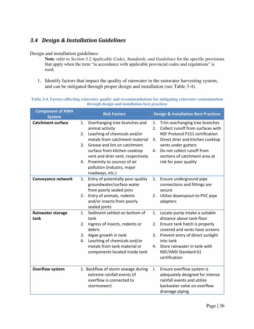
Page | 36
3.4 Design & Installation Guidelines
Design and installation guidelines:
Note: refer to Section 3.2 Applicable Codes, Standards, and Guidelines for the specific provisions that apply when the term ―in accordance with applicable provincial codes and regulations‖ is used.
1. Identify factors that impact the quality of rainwater in the rainwater harvesting system,
and can be mitigated through proper design and installation (see Table 3-4).
Table 3-4. Factors affecting rainwater quality and recommendations for mitigating rainwater contamination
through design and installation best practices
Component of RWH
System Risk Factors Design & Installation Best Practices
Catchment surface 1. Overhanging tree branches and
animal activity
2. Leaching of chemicals and/or
metals from catchment material
3. Grease and lint on catchment
surface from kitchen cooktop
vent and drier vent, respectively
4. Proximity to sources of air
pollution (industry, major
roadways, etc.)
1. Trim overhanging tree branches
2. Collect runoff from surfaces with
NSF Protocol P151 certification
3. Direct drier and kitchen cooktop
vents under gutters
4. Do not collect runoff from
sections of catchment area at
risk for poor quality
Conveyance network
1. Entry of potentially poor quality
groundwater/surface water
from poorly sealed joins
2. Entry of animals, rodents
and/or insects from poorly
sealed joints
1. Ensure underground pipe
connections and fittings are
secure
2. Utilize downspout-to-PVC pipe
adapters
Rainwater storage
tank
1. Sediment settled on bottom of
tank
2. Ingress of insects, rodents or
debris
3. Algae growth in tank
4. Leaching of chemicals and/or
metals from tank material or
components located inside tank
1. Locate pump intake a suitable
distance above tank floor
2. Ensure tank hatch is properly
covered and vents have screens
3. Prevent entry of direct sunlight
into tank
4. Store rainwater in tank with
NSF/ANSI Standard 61
certification
Overflow system
1. Backflow of storm sewage during
extreme rainfall events (if
overflow is connected to
stormsewer)
1. Ensure overflow system is
adequately designed for intense
rainfall events and utilize
backwater valve on overflow
drainage piping

Page | 37
2. Determine rainwater quality and treatment requirements:
a. In the Province of Alberta, rainwater may be used for: i. Toilet and urinal flushing, and
ii. Sub-surface irrigation. b. Consult the applicable provincial codes and regulations to verify the fixtures for
which connection to rainwater is permitted; c. Consult the applicable provincial codes and regulations and local authorities
regarding quality and treatment requirements for the permitted rainwater fixtures; d. Treatment recommendations (provided for guidance purposes only):
i. For typical single family residential dwellings consult the recommendations in Table 3-5.
Table 3-5. Treatment recommendations for typical single family residential dwellings
Rainwater Fixtures Recommended Degree
of Treatment1
Toilet and urinal flushing Treatment by pre-storage treatment device in
addition to the adoption of best practices
outlined in Table 3-4.
Sub-surface irrigation system Treatment by pre-storage treatment device in
addition to the adoption of best practices
outlined in Table 3-4.
Treatment by post-storage filtration device(s)
as required by irrigation system
manufacturer/contractor. 1Note: Recommendations only. Consult applicable provincial codes and regulations as well as
local authorities regarding permitted fixtures, quality targets and required treatment devices.
ii. For buildings other than a single family dwelling, the quality and
treatment requirements shall be in accordance with the latest edition of the Canadian Guidelines for Domestic Reclaimed Water for Use in Toilet and
Urinal Flushing. 3. Select and install pre-storage treatment devices:
a. Pre-storage treatment devices must be sized to handle the peak runoff from the catchment surface (refer to Section 1.4 Design & Installation Guidelines for further details regarding design rainfall intensity);
b. Filter frost protection: i. Locate the treatment device in a temperature-controlled environment
(maintained above 0°C), or ii. Locate the treatment device below the frost penetration depth, or where
burial below the frost penetration depth is not possible, locate the device below ground with appropriate insulation (refer to Appendix A for details), or
iii. Decommission/disconnect the treatment device from the conveyance network and drain the device prior to the onset of cold weather (refer to Section 2.4 Design & Installation Guidelines for details).

Page | 38
c. First-flush diverters: i. Size the first-flush chamber based on the desired amount of runoff (typical
diversion height is 0.5-1.5 mm) to divert from the storage tank, using the following formulas:
Equation 3-1
[ ]
Equation 3-2
ii. Estimate the collection losses:
1. Initial loss factor – Equal to the Diversion height (mm), 2. Continuous loss factor – Depends on the rate of flow through the
slow drip emitter. A 5% continuous loss can be assumed, or the continuous loss can be directly measured during a rainfall event.
d. Settling tank or a settling chamber: i. Size the settling tank or settling chamber based on the temporary storage
of a prescribed volume of runoff, 1. Where the prescribed volume can be based on rainwater height
(i.e., 5 mm of rain)13 , as given by:
Equation 3-3
2. Where the prescribed volume can be based on a percentage of the
capacity of the rainwater storage tank (i.e., settling chambers within two-compartment tanks typically have 1/3 the capacity of the storage chamber).
e. Pre-storage treatment filtration devices: i. The following components may be included as part of the filtering system:
1. High quality gutter guards, available from gutter contractors, 2. Leaf screens placed on the downspout, available from gutter
contractors, and/or 3. Commercially supplied rainwater filter installed in-line with
conveyance drainage pipe or inside tank. ii. Estimate the collection losses:
1. Initial loss factor – Reported by the supplier, or can be assumed to be negligible (0 mm),
2. Continuous loss factor – Reported by the supplier, or can be conservatively estimated at 20%.
13 Adapted from Performance Evaluation of a Rainwater Harvesting System. Interim report 2008. Toronto and Region Conservation Authority, Toronto, ON.

Page | 39
f. Pre-storage treatment devices shall be installed in accordance with applicable provincial codes and standards and manufacturer‘s instructions;
g. Pre-storage treatment devices shall be installed such that they are readily accessible. Access openings to facilitate entry into the device and/or tank shall be in accordance with the guidelines in Section 2.4 Design & Installation Guidelines.
4. When selecting and installing post-storage treatment device(s): a. Pre-storage treatment device(s) should also be utilized to minimize wear on post-
storage treatment devices; b. Post-storage treatment device(s) must be sized in accordance with the maximum
flow rate of the pressure system and manufacturer‘s requirements; c. Post-storage treatment devices shall be installed in accordance with applicable
provincial codes and standards and manufacturer‘s instructions; d. Post-storage treatment devices shall be installed such that they are readily
accessible.

Page | 40
3.5 Management Guidelines
1. Identify the factors that can impact the quality of rainwater in the RWH system, and take
steps to mitigate the risks posed by these factors by implementing the following maintenance activities:
a. Consult the maintenance best practices provided in Table 3-6.
Table 3-6. Factors affecting rainwater quality and recommendations for mitigating rainwater contamination
through maintenance best practices14
Component of RWH
System Risk Factors
Maintenance
Best Practices
Catchment surface
1. Proximity to sources of air
pollution (industry, major
roadways, etc.)
2. Overhanging tree branches
3. Animal activity
4. Leaching of chemicals and/or
metals from catchment material
At least once every 6 months:
Inspect catchment surface for
sources of contamination
(accumulated debris, leaves, pine
needles, etc.) and clean area
Trim overhanging tree branches
Conveyance network
1. Entry of potentially poor quality
groundwater/surface water from
poorly sealed joins
2. Entry of animals, rodents and/or
insects from poorly sealed joins
At least once every 6 months:
Inspect gutters for sources of
contamination (accumulated
debris, leaves, pine needles, etc.)
and clean gutters as required
Inspect area(s) where downspouts
connect to conveyance network to
ensure fittings are secure
Inspect pre-storage treatment
device(s) connected with
conveyance network and clean
devices as required
Rainwater storage tank
1. Leaching of chemicals and/or
metals from rainwater tank
storage material
2. Leaching of chemicals and/or
metals from components located
within rainwater tank
3. Pump intake located at bottom of
tank where it can draw in
sediment
At least once annually:
Inspect components inside tank
for signs of corrosion and/or
degradation and replace
components as necessary
Monitor rainwater quality at
point-of-use for indication of
sediment accumulation in tank.
b. Consider other site specific risk factor(s) and adapt the maintenance of the RWH
system as appropriate to mitigate the risks posed to rainwater quality.
14 Adapted from CSA B128.1-06/B128.2-06. Design and installation of non-potable water systems/Maintenance and field testing of non-potable water systems. 2006. CSA International, Toronto, ON.

Page | 41
2. Pre-storage treatment device(s) should be inspected at least twice per year, or more frequently as required by manufacturer‘s instructions and site conditions:
a. Observe rainwater passing through the device(s) during a rainfall event, or simulate a rainfall event by discharging water from a hose onto the catchment surface. Look for potential problems such as:
i. Accumulated dirt and debris blocking flow through filter, ii. Loose fittings or other problems with the treatment device(s) such that
rainwater is passing through without treatment taking place, or iii. Other problems with the treatment device(s).
b. Clean the filtration device(s) according to the manufacturer‘s maintenance instructions, repair as required.
3. If pre-storage treatment devices need to be decommissioned during the winter: a. Drain all of the rainwater accumulated in the treatment device; b. Disconnect the treatment device(s) from the conveyance network; and/or c. Install pipe, downspout or other material to bypass the pre-storage treatment
device(s) and direct untreated water to the tank. 4. Post-storage treatment device(s) should be inspected at least quarterly, or more frequently
depending upon manufacturer‘s instructions and site conditions: a. Observe the device(s) as water flows through the pressure system, looking for
problems such as: i. Water leaking from treatment device(s),
ii. Warning/indicator lights on treatment device(s) indicating fault with device and/or required replacement of components.
b. Maintain post-storage treatment devices as necessary through the regular cleaning of filtration device(s) and/or replacement of filter media, lamps, or other components as specified by the product manufacturer(s).
5. While inspecting, cleaning, or repairing the pre-storage treatment and/or post-storage treatment device(s) or other component of the rainwater harvesting system follow all necessary safety precautions.

Page | 42
Chapter 4. Make-up Water System and Backflow Prevention
4.1 Introduction
Regardless of the size of the rainwater storage tank or size of the catchment area, there will occasionally be times when there is insufficient rainfall to meet the demands placed on the RWH system, and the storage tank will run dry. RWH systems need to have a system in place to recognize when there is insufficient rainwater and perform an action such as triggering a warning light or switching to an alternative supply of water. This system is often referred to as a ―make-up‖ or ―back-up‖ system. The primary concern with a make-up system is that it requires water of high quality (from a municipality or private water source) to be brought into close proximity with rainwater, typically of poorer quality. In such situations, there is a risk of a cross-connection. If a connection is made between the RWH system and a municipal water system, there is a risk that the rainwater can be drawn into the potable water system through the process of backflow. Given these concerns surrounding cross-connections and backflow, care must be taken when implementing and managing a make-up water system. This chapter provides an overview of the various components that comprise a make-up system and gives guidance on how to assess and then mitigate the risks associated with cross-connection and backflow. Note: Proper design, installation and management must also be extended to the entire rainwater pressure system, since a cross-connection can potentially exist at any point in the system. Refer to Chapter 5. Pump and Pressurized Distribution System for further details.

Page | 43
4.2 Applicable Codes, Standards, and Guidelines
Table 4-1 references specific codes and standards that are applicable to make-up water systems and backflow prevention.
Table 4-1. Applicable standards, codes and guidelines for make-up water systems and backflow prevention
Applicable Codes,
Standards, and
Guidelines
Selected Provisions &
Design and Installation Implications
National Plumbing Code
of Canada
(2005)
2.2.10.15. Water Hammer Arresters
2.6.1.11. Thermal Expansion
2.6.2.1.(3) Connection of Systems
2.6.2.6. Premise Isolation
2.6.2.9. Air Gap
2.7.1.1. Not Permitted
Article 2.7.1.1. specifies that a RWH system (non-potable water system)
shall not be connected to a potable water system. The potable water
system shall be protected by means of an air gap (2.6.2.9.) for top-up
systems, and requires that RWH systems be installed with backflow
prevention devices as outlined by the National Plumbing Code (Sentence
2.6.2.1.(3) and Article 2.6.2.6.) and CAN/CSA-B64.10. When backflow
prevention devices are installed, thermal expansion tanks must also be
installed as per Article 2.6.1.11. When a solenoid valve is installed for a top-
up system, a water hammer arrester may be required in accordance Article
2.2.10.15.
CAN/CSA Standard
B64.10
(2001)
Appendix B, Table B1
4.3.4.2 Premise isolation
Specifies that where a potential connection exists between the RWH system
(non-potable water system) and potable water system, it must be protected
by means of an air gap or reduced pressure (RP) backflow prevention
device. Buildings with a RWH system (rated as a severe hazard
classification) must have premise isolation by means of a reduced pressure
(RP) backflow preventer.
Note: CSA B64.10 permits cross connections where adequate backflow
prevention is provided; however, Article 2.7.1.1. of the NPC prohibits such
connections. In cases of conflict with a referenced document the NPC
provision governs.
Canadian Electrical Code
(Current ed.)
All electrical equipment must be approved and
installed to according to the requirements of the
current edition Canadian Electrical Code
Mandatory Documents Supplementary Documents

Page | 44
Applicable Codes,
Standards, and
Guidelines
Selected Provisions &
Design and Installation Implications
CSA Standard B128.1
(2006)
6.0 Backflow prevention
11.2 Cross-connection testing
Specifies that backflow prevention devices shall comply with CAN/CSA-
B64.10 and the National Plumbing Code or the applicable provincial or
territorial plumbing code. Section 11.2 provides guidelines for testing cross-
connections after installation.
CAN/CSA Standard
B64.10
(2007)
Appendix B, Table B1
5.3.4 Premise isolation
Specifies that a dual check valve (DuC) shall be used to isolate a residential
premise with access to an auxiliary water supply (the RWH system), if there
is no direct connection between the auxiliary water supply and the potable
supply.
Note: Not legally binding. NPC (2005 ed.) references CAN/CSA B64.10 (2001
ed.). The next edition of the NPC (2010) may reference the 2007 edition of
B64.10.
Mandatory Documents Supplementary Documents

Page | 45
4.3 Issues for Consideration
Types of Make-up Water Systems
To ensure that rainwater demands are met during times when there is insufficient rainfall and the tank runs dry, there are two general options available:
1. Top-up – The rainwater storage tank can be partially filled, either manually or automatically, with make-up supplies of water from municipal (potable), or private water sources;
2. Bypass – The rainwater supply from the pressure system can be shut-off, either manually or automatically, and water from municipal or private sources can be directed through the rainwater pressure piping.
Of these options, only top-up systems are permitted by the National Plumbing Code 2005. The bypass method contravenes Subsection 2.7.1, of the Code which states that ―a non-potable water system shall not be connected to a potable water system.‖15 As such, this chapter focuses on top-up based make-up systems. The advantages and disadvantages associated with the manual and automatic top-up systems are discussed in Table 4-2.
Table 4-2. Advantages and disadvantages associated with top-up methods
Water Make-up
Method Advantages Disadvantages1
Manual top-up Simplest method to design and
install due to reduced control
equipment requirements
Lowest cost alternative
May result in service interruptions
(i.e., no water for flushing toilets) if
tank not topped-up prior to going dry
Requires homeowner to monitor
volume of stored rainwater in tank
and top-up pre-emptively if low
Automatic top-up Reduces the number of service
interruptions by automatically
filling tank prior to it running dry
Make-up system operates without
the need for monitoring or
intervention by the homeowner
Improper design or installation of
control equipment may cause
insufficient or excessive top-up
volumes to be dispensed by the
make-up system
Service interruption during power
failure 1 Note: Improper design, installation and/or management of all make-up systems may result in risk of
cross-connection with the potable water supply.
15 National Plumbing Code of Canada. 2005. National Research Council of Canada, Ottawa, ON.

Page | 46
For the majority of residential applications, it is recommended that the automatic top-up be selected as it minimizes service interruptions and is the least onerous for the home-owner. An automatic top-up system is depicted in Figure 4-1 and the various components are described below.
Figure 4-1. Components of an automatic top-up system
Rigid structure
Cable ties
ON
OFF
Electrical wire
Rainwater tank
Pump intake
OFF
ON Volume of top-up water
Dead space
Jet pump
Tether point
Air gap
Float switch (N/C)
Float switch (N/O)
Top-up drainage piping
Solenoid valve (N/C) on potable water
supply pipe

Page | 47
Control Equipment
The control equipment used to construct a make-up water system are listed in Table 4-3.
Table 4-3. Control equipment for make-up water systems
Control Equipment Description Devices/
Options Available
Water level sensor A device inside the tank that
is used to sense the level of
water
Can control (turn on or off)
warning lights, solenoid
valves and/or pumps, based
on water level
Float switch
Ultrasonic level sensor
Liquid level switch
(Float switch is typically used for
residential applications).
Shut-off valve A device that is manually
opened (or closed) to permit
(or prevent) the flow of
water
Integrated into the RWH
pressure system to manage
flow of water and isolate
components of the make-up
system (i.e., solenoid valves
and backflow preventers)
Types: ball valve, gate valve
The shut-off valve(s) selected
must be approved for handling
water that is under pressure.
Solenoid valve (automated
shut-off valve)
A valve that actuates (opens
or closes) automatically
when electricity is applied to
it
Connected with water level
sensor to activate make-up
water system
Come in a variety of
configurations
The solenoid valves selected
must be approved for handling
water that is under pressure.
When selecting control equipment for the make-up system, the following issues must be considered.
Sizing
All control equipment must be appropriately sized. Of particular concern for top-up based systems is the sizing of the top-up drainage piping. This pipe must be sized according to gravity flow, not pressurized flow, to prevent water backing up the pipe. In addition, all valves and backflow preventers must also be sized to be the same diameter as the diameter of the pipe(s) to which they are connected.
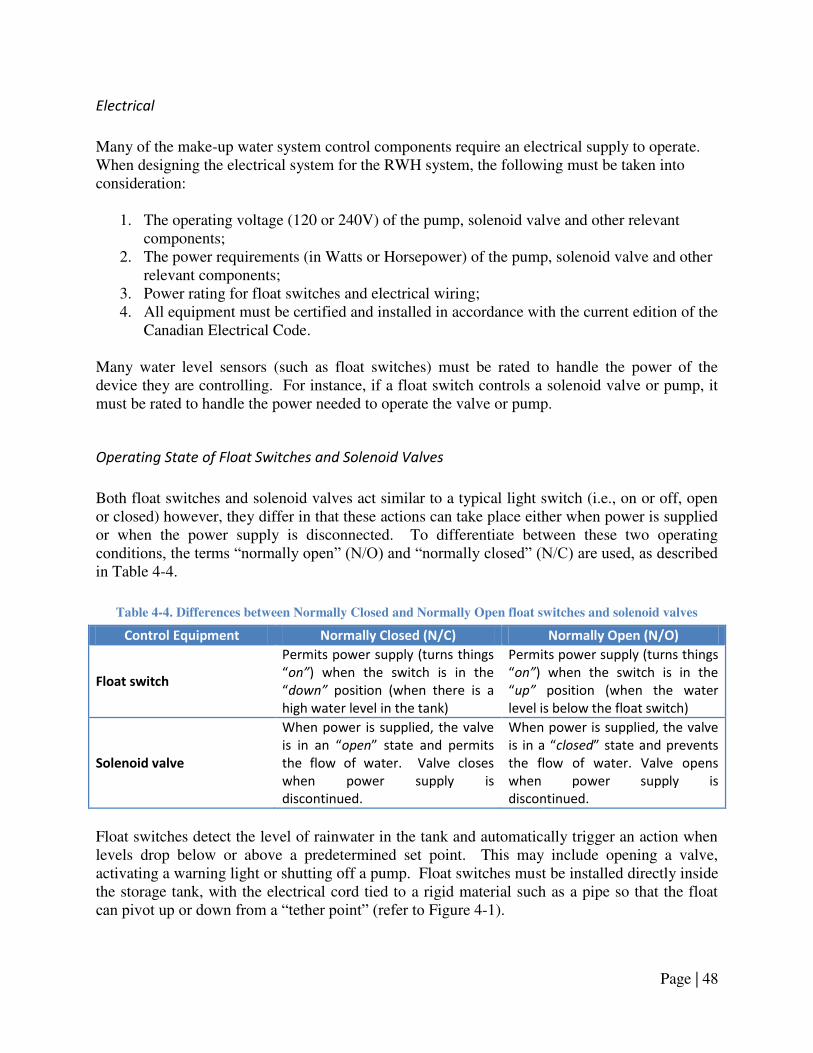
Page | 48
Electrical
Many of the make-up water system control components require an electrical supply to operate. When designing the electrical system for the RWH system, the following must be taken into consideration:
1. The operating voltage (120 or 240V) of the pump, solenoid valve and other relevant components;
2. The power requirements (in Watts or Horsepower) of the pump, solenoid valve and other relevant components;
3. Power rating for float switches and electrical wiring; 4. All equipment must be certified and installed in accordance with the current edition of the
Canadian Electrical Code. Many water level sensors (such as float switches) must be rated to handle the power of the device they are controlling. For instance, if a float switch controls a solenoid valve or pump, it must be rated to handle the power needed to operate the valve or pump.
Operating State of Float Switches and Solenoid Valves
Both float switches and solenoid valves act similar to a typical light switch (i.e., on or off, open or closed) however, they differ in that these actions can take place either when power is supplied or when the power supply is disconnected. To differentiate between these two operating conditions, the terms ―normally open‖ (N/O) and ―normally closed‖ (N/C) are used, as described in Table 4-4.
Table 4-4. Differences between Normally Closed and Normally Open float switches and solenoid valves
Control Equipment Normally Closed (N/C) Normally Open (N/O)
Float switch
Permits power supply (turns things
on”) when the switch is in the
down” position (when there is a
high water level in the tank)
Permits power supply (turns things
on”) when the switch is in the
up” position (when the water
level is below the float switch)
Solenoid valve
When power is supplied, the valve
is i a open state a d pe its the flow of water. Valve closes
when power supply is
discontinued.
When power is supplied, the valve
is i a closed state a d p e e ts the flow of water. Valve opens
when power supply is
discontinued.
Float switches detect the level of rainwater in the tank and automatically trigger an action when levels drop below or above a predetermined set point. This may include opening a valve, activating a warning light or shutting off a pump. Float switches must be installed directly inside the storage tank, with the electrical cord tied to a rigid material such as a pipe so that the float can pivot up or down from a ―tether point‖ (refer to Figure 4-1).
Page | 49
In a top-up system, a N/C switch is used in conjunction with a N/C solenoid valve. When in the down position, the float switch electrifies the solenoid valve, causing it to open and top-up the tank with water from the potable water system. The volume of make-up water used is dependent upon the ―tether length‖ of the float switch (illustrated in Figure 4-1), with longer tether lengths requiring greater make-up volumes before the use of rainwater resumes. The tether point sets the height (liquid level) at which this process takes place, with higher tether points initiating this process earlier (and leaving more unused rainwater, or ―dead space,‖ at the bottom of the tank). To maximize rainwater use, the tether length should be as short as possible and the tether point should be as low as possible, while providing enough water for the pump. This system theoretically provides dry run protection because the pump intake is located below the low water level (down position of the switch). Dry running occurs when the pump attempts to operate when there is insufficient rainwater in the tank and can cause the pump to overheat and become damaged. However, if the float switch controlling the solenoid valve fails, or if insufficient make-up water is available, dry running may still occur. A second float switch (N/O) should be connected to the pump, and located below the N/C float switch, to shut off the pump and ensure dry run protection in these cases. Similarly, a N/O switch should be used to shut off the pump where a manual top-up system is in place as there is the likelihood that the storage tank will run dry before make-up water is supplied. Some pumps may have built in dry run protection, however, this protection is not appropriate for RWH systems if it is based on a timer and not water levels.
Cross-connections, Backflow Prevention and Premise Isolation
With RWH systems, the risk of cross-connection is highest at the make-up system, as it requires that water from a potable water system be brought into close proximity with non-potable rainwater. A cross-connection is defined as ―any actual or potential connection between a potable water system and any source of pollution or contamination‖16 (emphasis added). If a connection is made between the rainwater pressure piping and the potable water system, backflow17 may occur, if pressure in the rainwater pressure piping is too high and/or the pressure in the potable water system is too low. Rainwater may unintentionally be drawn into the potable water supply of the house or building, or drawn into the entire water supply system of a municipality and be used to meet potable water applications. Because of these risks, both to the individuals in the home or building, and the residents of the municipality, backflow prevention measures are applied on two distinct levels:
16 CAN/CSA-B64.10-07/B64.10.1-07. Selection and Installation of Backflow Preventers/Maintenance and Field Testing of Backflow Preventers. 2007. CSA International, Toronto, ON. 17 Backflow is defined as ―a flowing back or reversal of the normal direction of flow‖. CAN/CSA-B64.10-07/B64.10.1-07. Selection and Installation of Backflow Preventers/Maintenance and Field Testing of Backflow Preventers. 2007. CSA International, Toronto, ON.
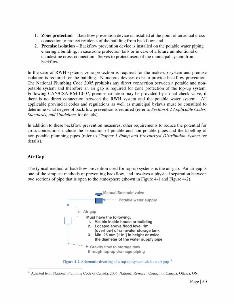
Page | 50
1. Zone protection – Backflow prevention device is installed at the point of an actual cross-
connection to protect residents of the building from backflow; and 2. Premise isolation – Backflow prevention device is installed on the potable water piping
entering a building, in case zone protection fails or in case of a future unintentional or clandestine cross-connection. Serves to protect users of the municipal system from backflow.
In the case of RWH systems, zone protection is required for the make-up system and premise isolation is required for the building. Numerous devices exist to provide backflow prevention. The National Plumbing Code 2005 prohibits any direct connection between a potable and non-potable system and therefore an air gap is required for zone protection of the top-up system. Following CAN/CSA-B64.10-07, premise isolation may be provided by a dual check valve, if there is no direct connection between the RWH system and the potable water system. All applicable provincial codes and regulations as well as municipal bylaws must be consulted to determine what degree of backflow prevention is required (refer to Section 4.2 Applicable Codes,
Standards, and Guidelines for details). In addition to these backflow prevention measures, other requirements to reduce the potential for cross-connections include the separation of potable and non-potable pipes and the labelling of non-potable plumbing pipes (refer to Chapter 5 Pump and Pressurized Distribution System for details).
Air Gap
The typical method of backflow prevention used for top-up systems is the air gap. An air gap is one of the simplest methods of preventing backflow, and involves a physical separation between two sections of pipe that is open to the atmosphere (shown in Figure 4-1 and Figure 4-2).
Figure 4-2. Schematic drawing of a top-up system with an air gap
18
18 Adapted from National Plumbing Code of Canada. 2005. National Research Council of Canada, Ottawa, ON.
Manual/Solenoid valve
Air gap
Must have the following: 1. Visible inside house or building 2. Located above flood level rim
(overflow) of rainwater storage tank 3. Min. 25 mm [1 in.] in height or twice
the diameter of the water supply pipe
Gravity flow to storage tank through top-up drainage piping
Potable water supply

Page | 51
This physical break prevents the backflow of water since even if rainwater backed up from the tank to the gap, it would spill from the gap and not come into contact with the potable water supply. The air gap must be located higher than the overflow drainage piping from the tank and the overflow drainage piping must remain free of blockage so that excess rainwater flows to the overflow system and does not back up and overflow at the air gap.

Page | 52
4.4 Design & Installation Guidelines
Design and installation guidelines:
Note: refer to Section 4.2 Applicable Codes, Standards, and Guidelines for the specific provisions that apply when the term ―in accordance with applicable provincial codes and regulations‖ is used.
1. Determine the type of make-up system:
a. Automatic top-up system (recommended); b. Manual top-up system; c. No make-up system (not recommended).
2. Plan the layout of the top-up system: a. A top-up system is generally comprised of the following:
i. Water level sensor(s) located in the rainwater storage tank, ii. A solenoid valve located on the potable water supply pipe,
iii. An air gap, iv. Top-up drainage piping conveying make-up water to the rainwater storage
tank, and v. Electrical conduit(s), containing wiring from the water level sensor(s) and
pump. b. Determine the location of the solenoid valve and air gap in accordance with the
guidelines provided below; c. Plan route of top-up drainage piping from the air gap to the tank (refer to Section
1.4 Design & Installation Guidelines for guidelines and applicable provincial codes and regulations regarding drainage piping);
d. Plan route of electrical conduit(s) from the location of the solenoid valve and power supply to the tank (refer to Section 1.4 Design & Installation Guidelines for piping installation guidelines);
e. Ensure that there are no buried service lines (gas, electricity, water, stormwater, wastewater, phone, or cable lines) in the area where digging will take place to accommodate the buried top-up drainage piping and/or electrical conduit by contacting the municipality and service providers.
3. Water level sensors: a. Select the appropriate water level sensor(s) for the RWH system (float switch,
ultrasonic level sensor, or other); b. Float switches:
i. Select the type of float switch: 1. Solenoid valve actuation is typically provided by a N/C float
switch, for top-up systems, 2. Pump dry run protection is typically provided by a N/O float
switch. ii. Electrical requirements:
1. The voltage rating of the float switch must match that of the device it controls (120 V or 240 V),
2. The power rating (Watts [W] or Horsepower [HP]) of the float switch must be sufficient to carry the total load of the device it

Page | 53
controls, or alternatively, float switches may be low voltage and used to activate the pump through relays in a control panel,
3. Spliced electrical wiring must be water tight and be of sufficient electrical rating as determined by the loads handled by the float switch and the total length of wiring,
4. All electrical connections for float switches must be made by a licensed electrician in accordance with the manufacturer‘s instructions.
c. Float switch installation: i. The float switch shall be tethered to a rigid freestanding object, such as a
vertical section of pipe or the pump, that: 1. Permits the float switch to rise and fall without any obstructions, 2. Is located in area where it is easily accessible and can be
withdrawn from the tank without requiring entry into the tank. ii. To set the operating parameters of the float switch:
1. To maximize rainwater collection, the tether length should be as short as possible: 75 mm [3 in.]. Refer to the manufacturer‘s installation instructions for details,
2. To maximize rainwater collection, the tether point should be as low as possible (such that the float is 50 mm [2 in.] above the pump intake when in the down position),
3. If utilizing a dual float switch configuration, the float switch controlling the solenoid valve should be located a minimum of 75 mm [3 in.] above the float switch controlling the pump.
d. Other water level sensors shall be selected and installed in accordance with applicable provincial codes and regulations, where all electrical connections must be made by a licensed electrician in accordance with the manufacturer‘s instructions.
4. Solenoid valves and shut-off valves: a. Select the type and size of solenoid valve and/or shut-off valve:
i. All valves must be suitable for potable water and pressure applications, ii. Valve openings must be no less than the size of the piping where they are
located, iii. Top-up systems typically use a N/C solenoid valve, iv. Solenoid valves with a ‗slow close‘ or ‗soft close‘ are recommended.
b. Electrical requirements: i. Solenoid valves must be wired into a power supply in conjunction with a
water level sensor; c. Solenoid valve and shut-off valve installation:
i. Solenoid valves or shut-off valves used as part of a top-up system shall be installed on the potable water supply pipe upstream of the air gap,
ii. Solenoid valves must be installed by a licensed plumber and electrician in accordance with the manufacturer‘s installation instructions.
d. Water hammer protection: i. If a ‗slow close‘ or ‗soft close‘ solenoid valve is not utilized a water
hammer arrester shall be installed on the potable water supply piping
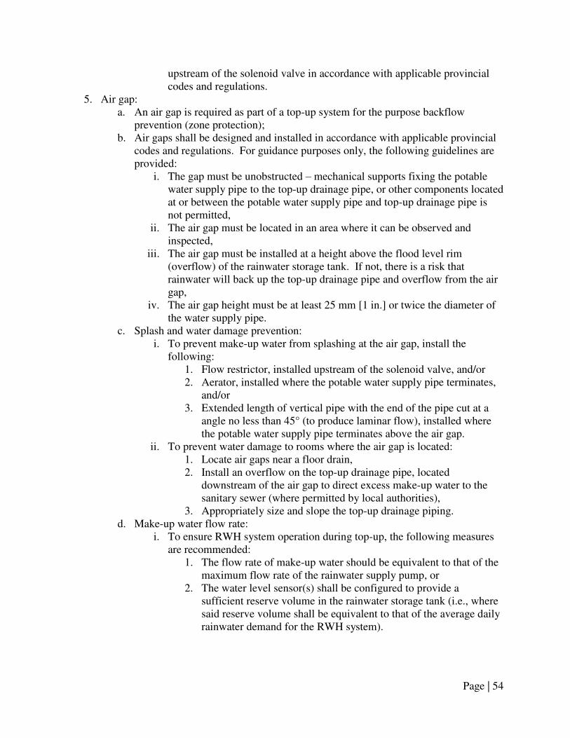
Page | 54
upstream of the solenoid valve in accordance with applicable provincial codes and regulations.
5. Air gap: a. An air gap is required as part of a top-up system for the purpose backflow
prevention (zone protection); b. Air gaps shall be designed and installed in accordance with applicable provincial
codes and regulations. For guidance purposes only, the following guidelines are provided:
i. The gap must be unobstructed – mechanical supports fixing the potable water supply pipe to the top-up drainage pipe, or other components located at or between the potable water supply pipe and top-up drainage pipe is not permitted,
ii. The air gap must be located in an area where it can be observed and inspected,
iii. The air gap must be installed at a height above the flood level rim (overflow) of the rainwater storage tank. If not, there is a risk that rainwater will back up the top-up drainage pipe and overflow from the air gap,
iv. The air gap height must be at least 25 mm [1 in.] or twice the diameter of the water supply pipe.
c. Splash and water damage prevention: i. To prevent make-up water from splashing at the air gap, install the
following: 1. Flow restrictor, installed upstream of the solenoid valve, and/or 2. Aerator, installed where the potable water supply pipe terminates,
and/or 3. Extended length of vertical pipe with the end of the pipe cut at a
angle no less than 45° (to produce laminar flow), installed where the potable water supply pipe terminates above the air gap.
ii. To prevent water damage to rooms where the air gap is located: 1. Locate air gaps near a floor drain, 2. Install an overflow on the top-up drainage pipe, located
downstream of the air gap to direct excess make-up water to the sanitary sewer (where permitted by local authorities),
3. Appropriately size and slope the top-up drainage piping. d. Make-up water flow rate:
i. To ensure RWH system operation during top-up, the following measures are recommended:
1. The flow rate of make-up water should be equivalent to that of the maximum flow rate of the rainwater supply pump, or
2. The water level sensor(s) shall be configured to provide a sufficient reserve volume in the rainwater storage tank (i.e., where said reserve volume shall be equivalent to that of the average daily rainwater demand for the RWH system).
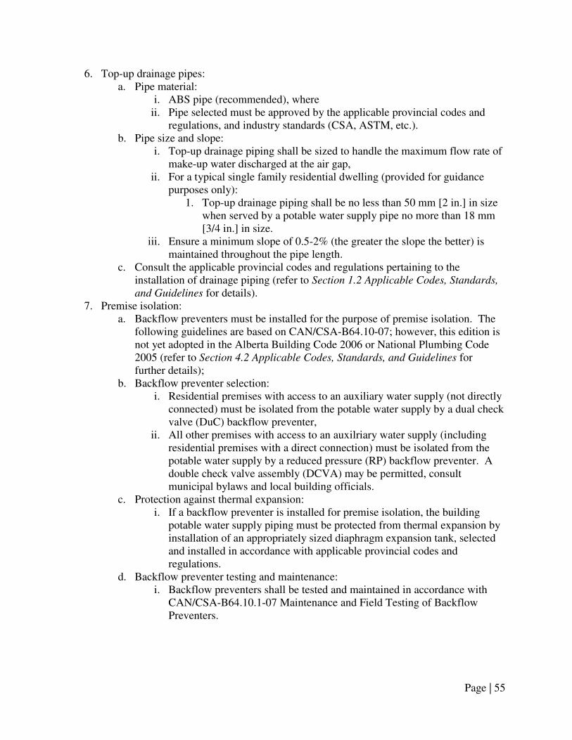
Page | 55
6. Top-up drainage pipes: a. Pipe material:
i. ABS pipe (recommended), where ii. Pipe selected must be approved by the applicable provincial codes and
regulations, and industry standards (CSA, ASTM, etc.). b. Pipe size and slope:
i. Top-up drainage piping shall be sized to handle the maximum flow rate of make-up water discharged at the air gap,
ii. For a typical single family residential dwelling (provided for guidance purposes only):
1. Top-up drainage piping shall be no less than 50 mm [2 in.] in size when served by a potable water supply pipe no more than 18 mm [3/4 in.] in size.
iii. Ensure a minimum slope of 0.5-2% (the greater the slope the better) is maintained throughout the pipe length.
c. Consult the applicable provincial codes and regulations pertaining to the installation of drainage piping (refer to Section 1.2 Applicable Codes, Standards,
and Guidelines for details). 7. Premise isolation:
a. Backflow preventers must be installed for the purpose of premise isolation. The following guidelines are based on CAN/CSA-B64.10-07; however, this edition is not yet adopted in the Alberta Building Code 2006 or National Plumbing Code 2005 (refer to Section 4.2 Applicable Codes, Standards, and Guidelines for further details);
b. Backflow preventer selection: i. Residential premises with access to an auxiliary water supply (not directly
connected) must be isolated from the potable water supply by a dual check valve (DuC) backflow preventer,
ii. All other premises with access to an auxilriary water supply (including residential premises with a direct connection) must be isolated from the potable water supply by a reduced pressure (RP) backflow preventer. A double check valve assembly (DCVA) may be permitted, consult municipal bylaws and local building officials.
c. Protection against thermal expansion: i. If a backflow preventer is installed for premise isolation, the building
potable water supply piping must be protected from thermal expansion by installation of an appropriately sized diaphragm expansion tank, selected and installed in accordance with applicable provincial codes and regulations.
d. Backflow preventer testing and maintenance: i. Backflow preventers shall be tested and maintained in accordance with
CAN/CSA-B64.10.1-07 Maintenance and Field Testing of Backflow Preventers.

Page | 56
8. Electrical wiring: a. All electrical wiring must be installed in accordance with the applicable
provincial codes and regulations, including the current edition of the Canadian Electrical Code.
9. Electrical conduit and rainwater service conduit: a. Wiring located underground shall be provided with mechanical protection by
means of an electrical conduit, or other approved means; b. To facilitate repair and/or replacement of underground rainwater pressure piping,
piping should be installed inside a rainwater service conduit, where the conduit material can be flexible drainage tubing (typically referred to as ―Big ‗O‘ ‖ tubing) or other suitable material.

Page | 57
4.5 Management Guidelines
1. Following the installation of the RWH system, if the make-up system does not operate, or
if it operates under conditions when it should not (i.e., tops-up the tank when there is a sufficient quantity of rainwater in the tank):
a. Ensure that the proper control equipment were selected and arranged in accordance with the provided Design & Installation Guidelines;
b. Visually examine the RWH system, in particular: i. Examine the volume of rainwater in the storage tank. If there is sufficient
rainwater in the tank, the make-up system should not operate and the fact that it is ―off‖ may indicate that it is functioning as intended,
ii. Examine the electrical supply to the rainwater pump, solenoid valve(s), and water level sensor(s) to verify that electricity is being supplied to all equipment,
iii. Examine the potable water supply pipe to verify that water flow is not being restricted by closed shut-off valve(s).
c. If the above steps do not resolve the problems with the make-up system, its performance must be verified by performing the following steps (Note: this
method assumes that a float switch is the water level sensor utilized, and must be
modified for other types of water level sensors using the manufacturer’s supplied troubleshooting instructions):
i. Float switch performance: 1. Visually examine the float switch(es) in the rainwater tank to
ensure that: a. They are properly tethered at the appropriate height and can
freely move up and down, b. They are not tangled with the pump or other components
located in the tank, c. Any electrical splicing of the float switch wire is intact.
2. Adjust and untangle the float switches if required, 3. Remove the float switch(es) and the structure to which they are
tethered from the rainwater tank, in order to test their performance, 4. If two float switches are present, the float switch at the lowest
elevation should control the rainwater pump (preventing dry running) and the other switch, at a higher elevation, should control solenoid valve(s) for a make-up system,
5. Simulate a low level event by holding the top float switch in the down position,
6. For top-up systems, the flow of make-up water should start, which can be observed through an air gap or from the storage tank lid/access hatch,
7. Next, simulate a high level event by holding the top float switch in the up position,

Page | 58
8. For top-up systems, the flow of make-up water should stop (as observed through an air gap or from the discontinuation of flow into the storage tank),
9. If another float switch is present in the tank, one which should control the pump in the event of low tank levels, this float switch should also be tested using the above method,
10. If the make-up system is operating under the opposite conditions as intended, then the problem lies in the type of float switches selected. If a N/O float switch is currently installed, then it must be replaced for a N/C float switch, and a N/C float switch must be replaced with a N/O float switch,
11. If no actions are observed under either float switch up or down scenarios, have the RWH system inspected by a licensed plumber and/or electrician.
ii. Solenoid valve performance: 1. Visually examine the solenoid valve(s) on the potable water supply
pipe and/or rainwater pressure piping. Ensure that each valve is connected to a power supply (i.e., electrical panel) and all manual shut-off valves located upstream of the solenoid valves are in the open position,
2. Determine if the solenoid valve(s) are operating following the float switch performance guidelines provided above. If make-up water flow cannot be easily observed, verify whether the solenoid valve(s) are operating by listening for a buzzing sound and/or checking the temperature of the solenoid valve coil,
3. If the solenoid valves do not appear to be operating, have the RWH system inspected by a licensed plumber and/or electrician.
iii. Top-up drainage pipe performance: 1. Determine if the problem lies with top-up drainage piping by
visually inspect the flow of water through the gap while performing the float switch performance evaluation (provided above) and/or simulating a top-up process by manually pouring water into the top-up drainage pipe through the air gap,
2. During the top-up process, if water overflows from the air gap, this may indicate some or all of the following problems:
a. The top-up drainage piping is undersized and/or the flow rate of make-up water is too high,
b. There is a blockage or obstruction in the top-up drainage piping,
c. If the system is operating under cold weather conditions, then water in the top-up drainage pipe may have frozen,
3. To address these issues, first attempt to decrease the flow rate of make-up water into the top-up drainage pipe, and observe the make-up process to see if this corrects the problem. If this problem arose during a period of extreme cold weather, it may be necessary to winterize or decommission the RWH system (refer to

Page | 59
the instructions in Chapter 2. Rainwater Storage & Tank Sizing for details) then monitor the performance of the make-up system after warmer temperatures are present,
4. If the above recommendations do not resolve the problem, the make-up system and top-up drainage piping may need to be examined and/or scoped by a licensed plumber to determine if any obstructions are in the pipe.
2. Backflow preventer testing and maintenance: a. Backflow preventers shall be tested and maintained in accordance with
CAN/CSA-B64.10.1-07 Maintenance and Field Testing of Backflow Preventers. 3. If the make-up system is operating properly, it is recommended that it still be inspected
once every six months to: a. Verify that the float switch wires are not tangled with other float switches, the
pump or other objects in the tank; b. Remove any dirt and/or debris that have accumulated on the float switch(es), if
present; c. Observe the make-up system while operating to ensure that water is not
overflowing from the top-up drainage pipe at the air gap and is not discharging from the backflow preventer(s). If any water leaking or discharging is observed, refer to the troubleshooting instructions above.
4. While inspecting, cleaning, or repairing the make-up system follow all necessary safety precautions, such as disconnecting the power supply when necessary.
Page | 60
Chapter 5. Pump and Pressurized Distribution System
5.1 Introduction
To supply rainwater to permitted fixtures a pump and pressurized distribution system is often required. Water is pumped from the rainwater tank, pressurized it, and delivered it to fixtures located at higher elevations in the building. The system is comprised of a pump, a ‗pressure tank‘ (a tank used to store pressurized water), a pressure switch or constant pressure components, independent plumbing lines and various other plumbing components. To ensure the proper operation of these systems, care must be taken when selecting the type and size of the pump and associated pressure tank. The pressure system must be capable of supplying water at a sufficient rate, and at a sufficient pressure to all the fixtures it is connected to, even those located the furthest distance from the pump. In addition, it must be designed and installed to minimize the risk of a cross-connection and potential backflow (refer to Chapter 4.
Make-up Water System and Backflow Prevention for further details). Homeowner maintenance is also critical, as homeowners must periodically inspect the system and be capable of troubleshooting the system if an issue with the pump does occur.

Page | 61
5.2 Applicable Codes, Standards, and Guidelines
Table 5-1 references specific codes and standards that are applicable to pressure systems.
Table 5-1. Applicable standards, codes and guidelines for pump and pressure distribution systems
Applicable Codes,
Standards, and
Guidelines
Selected Provisions &
Design and Installation Implications
Alberta Building Code
(2006)
7.2.1.2.(8) Plumbing Systems and Fixtures
Specifies that rainwater shall not be connected to plumbing fixtures that
provide water for human consumption, cooking, cleaning, showering or
bathing.
National Plumbing Code
of Canada
(2005)
2.2.5.5. Polyethylene Pipe and Fittings
2.2.5.7. Crosslinked Polyethylene Pipe and Fittings
2.2.5.8. PVC Pipe and Fittings
2.2.5.9. CPVC, Pipe, Fittings and Solvent Cements
2.2.7.1. Copper and Brass Pipe
2.3.4.5. Support for Horizontal Piping
2.6.3. Size and Capacity of Pipes
2.7.1.1. Not Permitted
2.7.2.1. Markings Required
2.7.3.2. Outlets
Articles 2.2.5.5., 2.2.5.7., 2.2.5.8., 2.2.5.9. and 2.2.7.1. specify approved pipe
materials used for pressure applications. Article 2.3.4.5. provides
specifications for the support of piping.
Subsection 2.6.3. provides a method for sizing water distribution systems, as
per Tables 2.6.3.1 and 2.6.3.2 and Table A-2.6.1.1.(1).
Articles 2.7.1.1. and 2.7.2.1. specify that rainwater pressure pipes shall not
be connected to potable water pipes and that rainwater shall not discharge
into a sink, or where a potable outlet discharges or food/drink is prepared.
Rainwater pressure piping shall have markings that are permanent and
easily recognized, as per 2.7.2.1.
Canadian Electrical Code
(Current ed.)
All electrical equipment must be approved and installed to according to
the requirements of the current edition Canadian Electrical Code
Mandatory Documents Supplementary Documents

Page | 62
Applicable Codes,
Standards, and
Guidelines
Selected Provisions &
Design and Installation Implications
CSA Standard B128.1
(2006)
5 Installation Requirements
9 Pumps
10 Separation
11 Testing
12 Markings
Provides guidelines for the pipes, pumps and plumbing accessories used for
RWH systems, separation of rainwater pipes and potable water pipes and
testing for cross-connections, as well as the markings for rainwater service
pipes and outlets.
Mandatory Documents Supplementary Documents

Page | 63
5.3 Issues for Consideration
General
The pump and pressurized distribution system is comprised of a series of interconnected components, located both inside the rainwater tank and within the building. A typical pressure system for a rainwater tank in a below-ground application is shown in Figure 5-1.
Figure 5-1. Typical schematic of pump and pressurized distribution system for below-ground rainwater tank
As shown in Figure 5-1, rainwater is drawn from the storage tank by a submersible pump located directly inside the tank [1A] or a ―jet‖ pump located inside the building [1B]. This rainwater is
1A. SUBMERSIBLE PUMP (OR JET PUMP INTAKE)
2. RAINWATER PRESSURE PIPNG (RAINWATER SERVICE
PIPE)
5. ELECTRICAL
CONDUIT
3. WATER LEVEL SENSOR (FLOAT
SWITCHES SHOWN)
4. ELECTRICAL WIRING
11. SUB-SURFACE
IRRIGATION SYSTEM
6. ELECTRICAL
SUPPLY PANEL
10, TOILET/
URINAL
8. POST-STORAGE TREATMENT
UNITS
9. RAINWATER PRESSURE PIPING (RAINWATER SUPPLY
PIPE)
1B. JET PUMP
7. PRESSURE TANK

Page | 64
pumped through a rainwater pressure piping [2], which runs from the tank to a suitable location (such as a mechanical room or basement utility room) within the building. To protect the pump from dry running, water level sensors [3], such as float switches, are often used. The electrical wiring from the water level sensor(s) and pump (if applicable) are then run through a protective electrical supply conduit [5] to an electrical supply panel [6]. Inside the building, the rainwater pressure piping is connected to a pressure tank and/or pump control unit [7] (depending upon the style of pump). If the RWH system will incorporate post-storage treatment units [8], these must be installed after the jet pump and any pressure tank and/or control unit. Following treatment (if performed), an rainwater pressure piping [9] is run to the permitted fixtures [10-11].
Pump
To select the appropriate pump for a given RWH system, four criteria must be considered:
1. Pump location, controller configuration and voltage, 2. Pump flow rate, 3. Pump system pressure, or ―head,‖ and 4. Acceptability of service interruptions.
Pump Location, Controller Configuration and Voltage
As shown in Figure 5-1, either a submersible pump located inside the tank, or a jet pump located outside the tank in an indoor/enclosed location, may be used. Other types of exterior pumps are available as an alternative to jet pumps, such as vertical multi-stage pumps, however, these are generally more suited to multi-residential and commercial applications, and as such, shall not be discussed further. With regards to submersible and jet pumps, each has its advantages and disadvantages, which are discussed in Table 5-2.
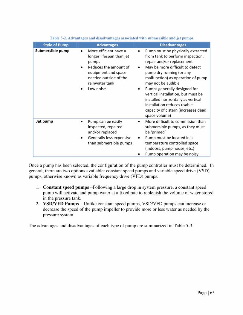
Page | 65
Table 5-2. Advantages and disadvantages associated with submersible and jet pumps
Style of Pump Advantages Disadvantages
Submersible pump More efficient have a
longer lifespan than jet
pumps
Reduces the amount of
equipment and space
needed outside of the
rainwater tank
Low noise
Pump must be physically extracted
from tank to perform inspection,
repair and/or replacement
May be more difficult to detect
pump dry running (or any
malfunction) as operation of pump
may not be audible
Pumps generally designed for
vertical installation, but must be
installed horizontally as vertical
installation reduces usable
capacity of cistern (increases dead
space volume)
Jet pump
Pump can be easily
inspected, repaired
and/or replaced
Generally less expensive
than submersible pumps
More difficult to commission than
submersible pumps, as they must
e p i ed
Pump must be located in a
temperature controlled space
(indoors, pump house, etc.)
Pump operation may be noisy
Once a pump has been selected, the configuration of the pump controller must be determined. In general, there are two options available: constant speed pumps and variable speed drive (VSD) pumps, otherwise known as variable frequency drive (VFD) pumps.
1. Constant speed pumps –Following a large drop in system pressure, a constant speed pump will activate and pump water at a fixed rate to replenish the volume of water stored in the pressure tank.
2. VSD/VFD Pumps – Unlike constant speed pumps, VSD/VFD pumps can increase or decrease the speed of the pump impeller to provide more or less water as needed by the pressure system.
The advantages and disadvantages of each type of pump are summarized in Table 5-3.

Page | 66
Table 5-3. Advantages and disadvantages associated with type of pump
Pump Controller
Configuration
Advantages Disadvantages
Constant speed
pump
Generally less expensive than
VSD/VFD pumps
Ideal for applications where
minor variations in water
pressure and flow rate are
acceptable (i.e., refilling toilet
tanks after flushing and operating
a garden hose)
Pressure tanks can be quite
large for applications
requiring high flow rates
Flow rate and system
pressure may spike when
pump activates, and
pressure may drop if water
demands are too high
Variable Speed
Drive/ Variable
Frequency Drive
pump
Provide constant pressure to
fixtures, regardless of demand
Use very small pressure tanks, or
micro-pressure tank inside the
pump or control unit
Often have built in low/high
voltage shutoff and dry run
protection
Smaller space requirements in
the building
Less electricity consumption than
comparable constant speed
pumps.
Use of smaller pressure
tanks requires a greater
u e of pu p sta ts potentially increasing pump
wear
More expensive than
constant speed pump
systems
The final decision regarding the type of pump is its operating voltage, either 120V or 240V. Pump manufacturers generally recommend using a 240 V supply for pumps as this tends to reduce the need for heavy gauge wiring and switching components. Before selecting either voltage however, it is recommended that the homeowner contact an electrician and the pump supplier to inquire regarding the appropriate pump and wire voltage. It is also important to note that any components wired in with the pump, such as water level sensors, operate at the same voltage as the pump. Refer to Chapter 4. Make-up Water System and Backflow Prevention for further details.
Pump Flow Rate
The amount of flow that must be generated by the pump depends on the types and number of fixtures connected to the distribution system. One method of determining this flow rate is to sum up the required flow rates for all of the fixtures, assuming a ‗worst case‘ scenario where all fixtures are operating at one time. This approach is not recommended, however, as it tends to over-size the pump, increasing the cost of the pump and pressure system. Instead, it is recommended that the pump flow rate be sized to handle a portion of this maximum flow, referred to as the ‗maximum peak flow.‘

Page | 67
Pump Head
Once the flow rate has been determined, the next task is to calculate the amount of pressure, or ―head,‖ the pump must provide. Two factors must be considered:
1. Required system pressure – This is the pressure required by the fixtures connected to the pump and pressurized distribution system, and
2. Total dynamic head (TDH) – This is the loss in pressure (or ―head loss‖) that takes place as water is lifted from a low elevation to a high elevation, and the losses that take place when water is being pumped through long stretches of pipe and fittings.
Total dynamic head is comprised of three components:
1. Static Lift is the height that water must be lifted before arriving at the pump (applicable only for systems utilizing a jet pump),
2. Static Height is the height from the pump to the furthest fixture, and 3. Friction Loss is the pressure loss when water travels through pipes and fittings.
Figure 5-2 illustrates the components of pump head.
Figure 5-2. Components of Total Dynamic Head (TDH)
Static Height
(m)
Static Lift
(m)
Friction Loss
(m)
Operating Pressure
(m)
Jet Pump
Operating Pressure + Friction Loss + Static Lift + Static Height Pump Head (m)
Total Dynamic Head (m)

Page | 68
Once both the pump head and the flow rate are determined, a pump can be selected using pump curves provided by manufacturers.
Acceptability of Service Interruptions
A final issue to consider is whether it is acceptable for non-potable water service to be interrupted by pump downtime or other potential problems associated with the RWH system. In a typical residential setting where rainwater is used for toilet flushing and outdoor use, infrequent service interruptions are likely to be generally acceptable, and no added measures are necessary. For residential settings where rainwater is used to supply much or all of household needs, or in multi-residential or commercial settings where water is needed for toilet and urinal flushing, service interruptions may not be acceptable. For such settings, two options are available: a dual-pump arrangement, often referred to as a duplex pump arrangement, can be installed, or an automatic bypass system can be utilized. A drawback of duplex pump arrangements is that they tend to be much more expensive than single-pump systems; however, many offer control equipment to periodically cycle between pumps, which improves the lifespan of both pumps. Another advantage of these pumps is that they can be purchased in a pre-assembled state, and be installed in much the same way as a typical single-pump arrangement. .
Pipes
There are two distinct sections of rainwater pressure piping:
1. Rainwater service pipe – the section of pipe from the storage tank to a jet pump, or the section of pipe from the storage tank to the pressure tank or control unit, in the case of submersible pumps;
2. Rainwater supply pipe – the section of pipe from the jet pump (or pressure tank/control unit for submersible pumps) to the permitted fixtures.
Each section has unique criteria that must be considered during design and installation, resulting in different pipe material, sizing and installation requirements. For instance, below-ground rainwater tanks require rainwater service pipe that is suitable for burial and, as this pipe will always have water in it, it is critical that it is well protected from freezing. Rainwater supply piping is inside the building and must be installed in accordance with codes to ensure that a cross-connection is not made. Both sections of pipes must be sized to handle the flow generated by the pump and ensure that each fixture receives rainwater at a sufficient rate, with service piping typically requiring larger pipe diameters than supply piping. To prevent cross-connections, rainwater piping must be marked to indicate that the pipes contain non-potable water. Markings for pipe must be distinct and easily recognizable, typically a purple

Page | 69
colour is used to identify the piping as containing non-potable water. An example of pipe marking is shown in Figure 5-3.
Figure 5-3. Typical marking for rainwater pressure piping
Another means of identifying rainwater pressure piping is to utilize a distinct colour of pipe – purple – to prevent future plumbing cross-connections.
Pressure Tank
Pressure tanks perform two functions in a pump and pressurized distribution system:
1. Store pressurized water to minimize the frequency of the pump cycling on and off, and 2. Maintain a constant pressure in the distribution system.
To accomplish these tasks, pressure tanks are comprised of an exterior shell with an inner bladder that is equipped with a pressure sensor connected to the pump. The pump starts when the pressure in the bladder drops to the cut-in point and shuts off when the pressure in the bladder reaches the cut-out point. Other than the pressure sensor, the most important factor to ensure proper operation of the pressure system is sizing the pressure tank so that it is compatible with the type of pump and the pump‘s flow rate. Constant speed pumps require larger pressure tanks than VSD/VFD pumps because they are designed store the volume of water discharged by the pump over a 1-2 minute period. This is the minimum time the pump is permitted to operate once activated and is referred to as ―pump run time‖. A longer pump run time requires a larger pressure tank, but minimizes wear due to frequent pump starts. For VSD/VFD pumps, the size and style of pressure tank tends to vary by manufacturer. Some manufacturers specify the use of small (~1 Gallon) tanks that are installed in a similar manner to larger pressure tanks, whereas others incorporate micro-pressure tanks inside the pump, or in a control panel.
WARNING: NON-POTABLE WATER — DO NOT DRINK
AVERTISSEMENT : EAU NON-POTABLE — NE PAS BOIRE

Page | 70
5.4 Design & Installation Guidelines
Design and installation guidelines:
Note: refer to Section 5.2 Applicable Codes, Standards, and Guidelines for the specific provisions that apply when the term ―in accordance with applicable provincial codes and regulations‖ is used.
1. Determine the fixtures connected to rainwater:
a. In the Province of Alberta, rainwater may be used for: i. Toilet and urinal flushing, and
ii. Sub-surface irrigation. b. Consult the applicable provincial codes and regulations to verify the fixtures for
which connection to rainwater is permitted. 2. Select the pump:
a. Determine the style and operating characteristics: i. Style: jet pump or submersible pump,
ii. Controller configuration: constant speed or variable speed drive (VSD), iii. Operating voltage: 120V or 240V.
b. Determine the required flow rate: i. Consult applicable codes and regulations, industry standards, local
authorities and irrigation system manufacturer (if applicable) regarding the minimum flow rate to be supplied by the pump,
ii. For guidance purposes only, a method for estimating minimum pump flow rate, based upon the maximum peak demand sizing method, is provided in Appendix C.
c. Determine the pump head: i. Consult applicable codes and regulations regarding the minimum flow
pressure and maximum static pressure provided by the pump, ii. A method for determining the pump head is provided in Appendix C.
d. Consult the pump manufacturer or supplier, or use pump manufacturer‘s ‗pump curve‘ charts, to select the appropriate pump model, given the pump style and operating characteristics, required flow rate, and pump head.
e. If pump downtime is not permitted or not desired: i. Provide a generator or battery backup for the pump, and/or
ii. Provide a backup pump or duplex pump arrangement. 3. Select the pressure tank:
a. Consult the pump manufacturer or supplier regarding the minimum size of pressure tank for the pump, based upon pump controller configuration, and pump flow rate;
b. For guidance purposes only, a method for sizing the pressure tank for constant speed pumps is provided in Appendix C.
Page | 71
4. Plan the layout of the pump and pressurized distribution system: a. Plan route of the rainwater service piping from the jet pump, pressure tank or
control unit to the tank (refer to Section 1.4 Design & Installation Guidelines for guidelines and applicable provincial codes and regulations regarding installation of underground piping);
b. Plan route of the rainwater supply piping from the jet pump, pressure tank or control unit to the permitted fixtures;
c. Plan route of electrical conduit(s) from the location of the power supply to the tank (route with float switch wiring where possible, refer to Chapter 4. Make-up
Water System and Backflow Prevention for further details); d. Ensure that there are no buried service lines (gas, electricity, water, stormwater,
wastewater, phone, or cable lines) in the area where digging will take place to accommodate buried rainwater service piping and/or electrical conduit by contacting the municipality and service providers.
5. Rainwater pressure piping: a. Rainwater pressure piping is comprised of two distinct sections of pipe:
i. Rainwater service pipe: 1. Piping from the storage tank to a jet pump, or 2. Piping from the storage tank to the pressure tank or control unit, in
the case of submersible pumps. ii. Rainwater supply pipe:
1. Piping from the jet pump (or pressure tank/control unit for submersible pumps) to the permitted fixtures.
b. Rainwater service pipes: i. Pipe material:
1. Polyethylene pipe (recommended), where 2. Pipe selected must be approved by applicable provincial codes and
industry standards (CSA, ASTM, etc.). ii. Pipe size:
1. Pipe shall be sized to handle the maximum flow rate of the pump in accordance with the pump manufacturer‘s instructions,
2. For estimation purposes, service pipe size can be calculated using the method provided in Appendix C.
iii. Tank connection: 1. Rainwater service piping should enter the tank at a height no lower
than that of the overflow drainage piping, or ideally, at a height 50 mm [2 in.] above the top of the overflow drainage pipe(s) entering the tank, or
2. Where entering the tank at a height no lower than that of the overflow drainage piping exposes the rainwater service piping to frost, rainwater service piping may enter the tank at a lower height, provided the tank connection is water tight.
c. Rainwater supply pipes: i. Pipe material:
1. Crosslinked polyethylene (PEX) (recommended), where

Page | 72
2. Pipe selected must be approved by applicable provincial codes and industry standards (CSA, ASTM, etc.).
ii. Pipe size: 1. Consult the applicable provincial codes and regulations pertaining
to water supply pipe sizing, 2. For estimation purposes, supply pipe size can be calculated using
the method provided in Appendix C. 6. Installation of rainwater pressure piping:
a. Connection: i. Rainwater pressure piping shall not be connected to a potable water
system, ii. Rainwater pressure piping shall only connect to fixtures permitted by
applicable provincial codes and regulations. b. Support and protection:
i. Underground piping shall be located in a properly excavated space, be supported and properly backfilled in accordance with applicable provincial codes and regulations,
ii. Piping inside a building shall be supported in accordance with applicable provincial codes and regulations,
iii. Piping shall be protected from frost (refer to Section 1.4 Design &
Installation Guidelines for details). c. Operation and maintenance considerations:
i. Rainwater service piping connected to a jet pump must be installed on a horizontal, or on a consistent upward slope from the storage tank to the pump,
ii. To minimize the possibility of leaks, underground rainwater service piping should be installed with no, or few, pipe fittings,
iii. To facilitate repair and/or replacement of underground rainwater service piping, piping should be installed inside a rainwater service conduit, where the conduit material can be flexible drainage tubing (typically referred to as ―Big ‗O‘ ‖ tubing) or other suitable material.
d. Underground non-metallic pipes should be installed with ‗tracer tape‘ (also referred to as ‗tracer wire‘) at a height of 300 mm [12 in.] above the pipe for the purpose of locating as-installed piping.
7. Pipe markings19 : a. All rainwater pressure pipes shall be clearly identified and marked in accordance
with applicable provincial codes and regulations; b. Pipes shall be marked as follows:
i. Text/legend: 1. WARNING: NON-POTABLE WATER — DO NOT DRINK
AVERTISSEMENT : EAU NON-POTABLE — NE PAS BOIRE 2. Text must be legible with letters no less than 5 mm in height,
except where pressure pipe size makes 5 mm high letters impractical.
19 Adapted from CAN/CSA-B128.1-06 Design and installation of non-potable water systems. 2006. CSA International, Mississauga, ON. Refer to CAN/CSA-B128.1-06 for further details.

Page | 73
ii. Colour: 1. Marking labels shall be purple in colour, and/or 2. Pipes shall be purple in colour, or marked with a continuous purple
stripe. iii. Figure 5-4 provides an example of typical pipe marking:
Figure 5-4. Typical marking for rainwater pressure piping
c. Spacing of markings:
i. Markings shall be repeated at intervals of not more than 1.5 m. 8. Installation of pump :
a. Pumps shall be installed in accordance with the manufacturer‘s installation instructions;
b. Pumps shall be installed such that they are readily accessible (submersible pumps must be retrievable without entry into the tank);
c. Pump shall be provided with dry run protection. Consult pump specifications to determine if pump has built-in dry run protection, if not, provide a water level sensor (refer to Chapter 4. Make-up Water System and Backflow Prevention for details);
d. For jet pumps: i. Rainwater service pipe should terminate no less than 100-150 mm [4-6 in.]
above the bottom of the tank, ii. Pump prime shall be maintained by a foot valve located at the rainwater
service pipe intake, or a check valve located in the rainwater service pipe upstream of the jet pump.
e. For submersible pumps: i. The pump intake should be located no less than 100-150 mm [4-6 in.]
above the bottom of the tank, ii. Pump prime shall be maintained a check valve located in the rainwater
service pipe downstream of the jet pump (consult pump manufacturer‘s instructions to determine if required).
f. Electrical requirements: i. All wiring must be installed in accordance with the current edition
Canadian Electrical Code. Refer to the pump manufacturer‘s installation instructions for further details,
ii. Electrical wiring installed outdoors and/or underground should be provided with protection,
iii. The pump should be installed on a dedicated circuit, with a motor disconnect switch installed near the pressure tank or control panel (refer to the Canadian Electrical Code for specifics),
iv. For buried tanks, electrical wiring should be suitable for burial and/or wiring should be run through a protective conduit made of PVC pipe, or ‗Big-O‘-style drainage pipe,
WARNING: NON-POTABLE WATER — DO NOT DRINK
AVERTISSEMENT : EAU NON-POTABLE — NE PAS BOIRE

Page | 74
v. Buried electrical wiring and/or conduits should be installed in a properly prepared and backfilled space (refer to Chapter 1. Rainwater Catchment &
Conveyance for details). 9. Installation of pressure tank:
a. Pressure tanks shall be installed in accordance with the manufacturer‘s installation instructions;
b. Pressure tanks shall be installed such that they are readily accessible; c. Pressure tanks shall be installed with a means for observing the system pressure,
such as a pressure gauge; d. The pressure sensor or pressure switch installed with the pressure tank must be
wired in with the pump (and a control panel if applicable); e. All wiring must be installed in accordance with the current edition Canadian
Electrical Code. 10. Install post-storage treatment devices as required (refer to Chapter 3. Rainwater Quality
& Treatment for details). 11. Commission the pump and pressurized distribution system in accordance with the
manufacturer‘s instructions. Instructions for a typical constant speed pump are provided in Section 5.5.

Page | 75
5.5 Management Guidelines
1. If the pump and pressurized distribution system stop operating, or if there are problems
during the commissioning process, follow the trouble shooting steps outlined below: a. Ensure that the proper pump and pressure equipment were selected and installed
in accordance with the provided Design & Installation Guidelines; b. Visually examine the volume of rainwater in the storage tank:
i. If the rainwater tank is empty, the pump and pressure system should not operate, and the fact that it is ―off‖ may indicate that a water level sensor connected to the pump, or the pump‘s internal dry run protection, is acting as intended and preventing the system from operating,
ii. If there is sufficient rainwater in the tank, and the pump and pressure are not operating, examine the electrical supply for the pump and pressure system. Verify that all necessary components are connected to the electricity supply, and that all components are supplied electricity (i.e., all on/off switches are in the ‗on‘ position and any electrical panel breakers are also in the ‗on‘ position),
iii. Note: In the event of a power failure, rainwater cannot be supplied to
connected fixtures unless back-up provisions such as an automatic bypass
back-up system were included in the design of the RWH system. 2. Most often a problem with the pump and pressurized distribution system is not due to the
pump itself but the associated components and equipment. The following steps are recommended for examining each of these components:
a. A licensed plumber, electrician or other skilled technician should be consulted regarding the troubleshooting and/or repair of the pump and pressure system. The following steps are provided only as a guide.
b. Make-up water system and water level sensors: i. During the visual inspection of the rainwater storage tank, if the tank
appeared empty, but the RWH system includes a top-up system, this may indicate that there are problems with the back-up system. Refer to Chapter 4. Make-up Water System and Backflow Prevention for instructions on how to troubleshoot this system,
ii. If the RWH system utilizes an automatic bypass make-up system, an empty tank may be normal given insufficient rainfall or heavy use. This system should automatically provide potable water to fixtures (bypassing the RWH system). If this system does not operate, or if pump operation does not resume following the addition of rainwater to the tank, this may indicate that there are problems with the back-up system,
iii. If a manual top-up or bypass back-up system is utilized, direct intervention is required to activate these systems. These systems must be activated prior to the storage tank running empty, otherwise a water level sensor connected to the pump, or the pump‘s internal dry run protection, will prevent the pump and pressure system from operating,
iv. If the top-up system appears to be functioning as intended, the problem with the pump and pressurized distribution system may lie with the water

Page | 76
level sensor connected to the pump. Instructions on how to inspect, test and adjust a float switch water level sensor is provided in Chapter 4.
Make-up Water System and Backflow Prevention. c. Pressure tank:
i. If the pump cycles on and off repeatedly, and/or the system never comes up to the desired pressure, there may be a problem with the pressure tank,
ii. The static pressure of the pressure tank (the pressure of the tank when there is no water inside of it) must be 14 kPa [2 psi] less than the desired cut-in pressure.
d. Pressure sensor/switch: i. Pump cycling and/or an inability to come up to the desired pressure may
also be a problem with the pressure sensor/switch, ii. For VSD/VFD pumps utilizing a pressure sensor, the pressure settings will
likely need to be set using a control panel (refer to the pump and pressure tank manufacturer‘s installation instructions for details),
iii. For constant speed pumps utilizing a pressure switch, consult the pump, and/or pressure switch manufacturers‘ instructions for instructions on adjusting the pressure switch.
e. Pipes and shut-off valves: i. If a jet pump appears to be dry running, or if a submersible pump appears
to run for a period of time, but does not discharge any water, there may be a blockage in the rainwater pressure piping,
ii. If the tank is located outdoors and below ground, there is a chance that under extreme cold conditions rainwater may have frozen in the pipes, preventing flow in the rainwater pressure piping. It may be necessary to wait for temperatures to increase to determine if this is the source of the problem,
iii. A blockage can also be created by a shut-off valve, located in the rainwater pressure piping, that is in the ‗closed‘ position. Inspect all shut-off valves to ensure they are open.
f. Foot valves, check valves and leaks in the system: i. If the pump cycles on during times when there is no rainwater demand or
if the pressure gauge shows that the system pressure slowly decreases over time, there may be a problem with the foot valve or check valve or there may be a leak in the system,
ii. Inspect all foot valves and check valves to ensure that they are installed in the correct orientation (as indicated on the device) and that the valve is not clogged by dirt and debris,
iii. If the foot valves and check valves appear to be operating properly, then there may be a leak in the rainwater pressure piping. Inspect all piping to ensure that there are no leaks from the pipelines or leaks from the fixtures connected to the pump and pressurized distribution system.
3. If the above steps do not resolve the issues with the pump and pressure system, the problem may lie directly with the pump. Refer to the pump manufacturer‘s operation instructions for troubleshooting recommendations, and if these actions are unsuccessful at

Page | 77
resolving the problem, consult a licensed plumber, electrician and/or pump service technician.
4. If the pump and pressurized distribution system is operating properly, it is recommended that it still be inspected once annually to:
a. Ensure that the pump and pressure system is in good working order, and that there is no obvious sign of pump overheating or pump wear;
b. Ensure that there are no leaks in the rainwater pressure piping; c. Observe the pressure system when no demands are placed on it. If the pump
cycles repeatedly during a period where no demands are present, this may indicate that there are problems with the foot valve or check valve, or that there is a leak in rainwater pressure piping.
5. While inspecting and/or repairing the components of the pump and pressurized distribution system, follow all necessary safety precautions, including disconnecting the electricity supply to the pump.

Page | 78
Chapter 6. Overflow Provisions & Stormwater Management
6.1 Introduction
On occasion, the volume of rainwater collected from the roof catchment will exceed the storage capacity of the rainwater storage tank, causing the tank to overflow. If overflow-handling provisions are not in place, excess rainwater will back up rainwater conveyance and top-up drainage piping, until the rainwater reaches a point from which it can most easily discharge/overflow. This may be at the downspout-to-conveyance drainage pipe transition, or less ideal locations like the access opening of the tank, or at the air gap of a top-up system. Overflows at these points may cause damage to the rainwater tank itself, or cause water damage to a building‘s exterior or interior. Due to the consequences of not properly handling excessive volumes of rainwater, it is important that the RWH system include sufficient overflow provisions. The design of overflow systems involves deciding where excess volumes of rain can be appropriately discharged, and how to convey these overflow volumes from the storage tank to the point of discharge. Addressing these issues generally falls under the practice of stormwater management. The practice of stormwater management has evolved considerably in the past decades, and has shifted from simply conveying stormwater off-site to managing it through on-site practices and treatment facilities designed to mitigate the environmental impacts of runoff. RWH systems are a new addition to stormwater management practices in Canada, and as such there is little guidance on how to integrate these systems with stormwater management programs. Despite lack of specific guidelines, many aspects of stormwater management remain applicable for handling the overflows of rainwater tanks. This chapter will discuss these stormwater management and regulatory requirements and provide guidance on how to select, install and manage the most appropriate type of overflow-handling system given these considerations and other issues such as site conditions, and tank location/ placement. Since there are very few federal or provincial regulations or guidelines on the design and installation of stormwater management systems, this chapter utilizes the Stormwater Management Planning and Design Manual from the Province of Ontario for general design criteria and method20.
20 Stormwater Management Planning and Design Manual. 2003. Ontario Ministry of the Environment, Toronto, ON.

Page | 79
6.2 Applicable Codes, Standards, and Guidelines
Table 6-1 references specific codes and standards that are applicable to overflow-handling systems.
Table 6-1. Applicable standards, codes and guidelines for rainwater overflow handling systems
Applicable Codes,
Standards, and
Guidelines
Selected Provisions &
Design and Installation Implications
National Plumbing Code
of Canada
(2005)
2.4.2.2. Connection of Overflows from Rainwater Tanks
Specifies that an overflow from a rainwater tank shall not be directly
connected to a drainage system (an indirect connection is required).
Note: Overflow drainage pipes must be sized and installed in accordance
with the NPC provisions applicable to drainage piping. See Chapter 1 for
details.
CSA Standard B128.1
(2006)
7.7 Overflow(s) capacity
7.8 Overflow discharge
Specifies that the capacity of the overflow drainage pipe(s) must be equal to
the capacity of the conveyance drainage pipes, and that overflows must be
discharged in accordance with local regulations.
Stormwater
Management Guidelines
for the Province of
Alberta
(1999)
6.3.3 On-lot Infiltration Systems
Provides brief description of lot-level infiltration systems.
Alberta Private Sewage
Systems Standard of
Practice
(2009)
7.1.1.2. Site Evaluation (2), (3)
7.1.2.1. Number of Soil Profiles Investigated
7.1.2.2. Minimum Depth of Soil Investigation
Provides guidelines on evaluating site soil profiles, which can be used in the
sizing of soakaway pits/infiltration trenches.
Mandatory Documents Supplementary Documents

Page | 80
6.3 Issues for Consideration
Overflow Discharge Locations
The purpose of the overflow system is to handle excessive rainwater flows, directing them away from the rainwater storage tank to a suitable location. Overflow volumes can be directed to grade, a storm sewer, or an on-site soakaway pit. In each case, rainwater can be conveyed via gravity flow or pumping. Table 6-2 describes these options and includes sketches illustrating each overflow-handling method. In these illustrations, rainwater entering the tank during a rainfall event (Qt) has exceeded the storage capacity of the tank (S).
Table 6-2. Overflow discharge locations and methods of conveying rainwater overflows
Overflow Discharge
Locations/Methods Illustration/Example
1. Discharge to grade via gravity flow
This method is applicable for tanks
located above- or below-grade where
rainwater overflows can be directed to
grade via gravity flow.
2. Discharge to grade via pump-
assisted flow
This method is applicable for tanks
located below-ground or integrated
within buildings, where rainwater
overflows must be pumped to grade 3. Discharge to storm sewer via gravity
flow
This method is applicable for tanks
located above- or below-grade where
rainwater overflows can be discharged
to a storm sewer via gravity flow,
although the tank cannot be directly
connected to the sewer1.
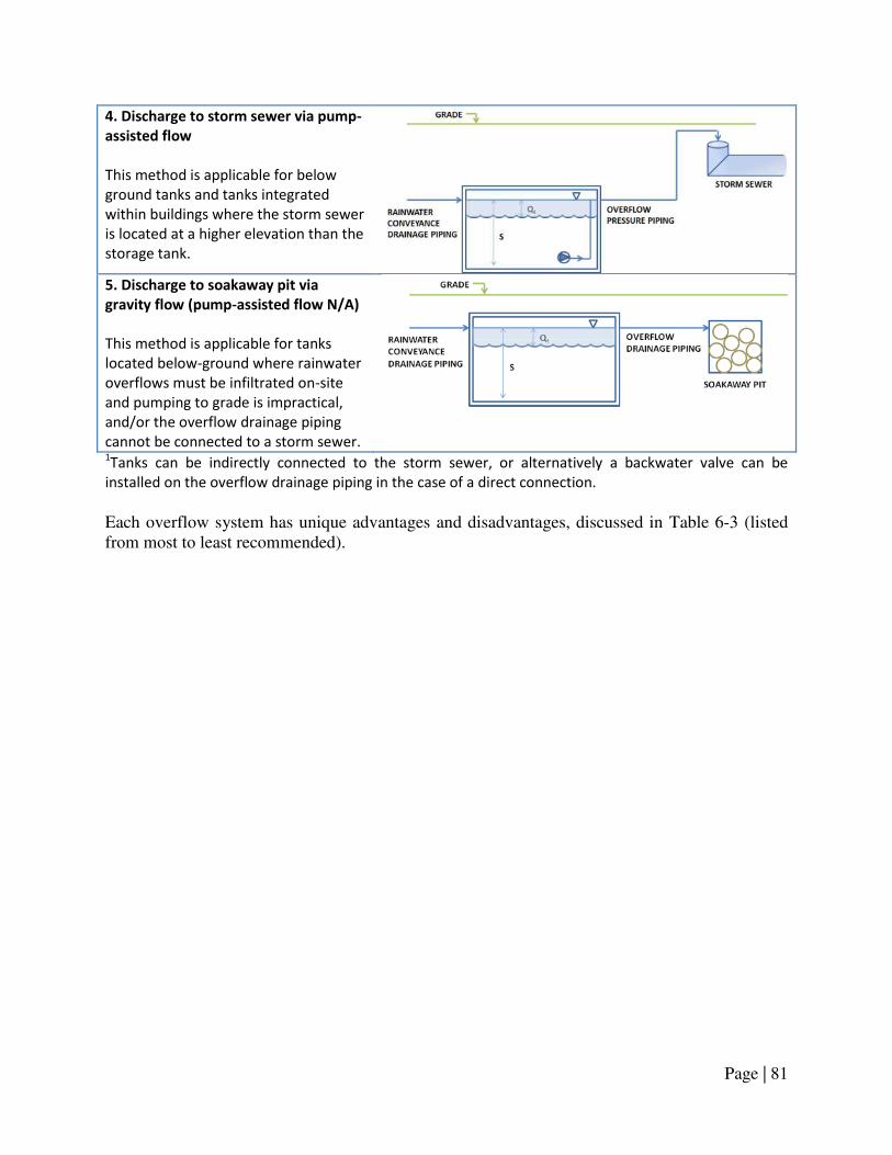
Page | 81
4. Discharge to storm sewer via pump-
assisted flow
This method is applicable for below
ground tanks and tanks integrated
within buildings where the storm sewer
is located at a higher elevation than the
storage tank.
5. Discharge to soakaway pit via
gravity flow (pump-assisted flow N/A)
This method is applicable for tanks
located below-ground where rainwater
overflows must be infiltrated on-site
and pumping to grade is impractical,
and/or the overflow drainage piping
cannot be connected to a storm sewer.
1Tanks can be indirectly connected to the storm sewer, or alternatively a backwater valve can be
installed on the overflow drainage piping in the case of a direct connection.
Each overflow system has unique advantages and disadvantages, discussed in Table 6-3 (listed from most to least recommended).

Page | 82
Table 6-3. Comparison of the advantages and disadvantages associated with overflow discharge
locations/methods
Overflow Discharge
Locations/Methods Advantages Disadvantages
Discharge to grade via
gravity flow
(most recommended)
Simplest method to design,
install and operate.
Low probability of rainwater
backing up the overflow
drainage piping
If discharge location not
prepared properly, may
cause soil erosion at site.
May pose a nuisance/safety
issue if discharging large
volumes from big catchment
surfaces.
Overflow drainage piping
may freeze if large sections
are above the frost
penetration depth; ice may
build up at the point of
discharge if not designed
properly.
Discharge to storm
sewer via gravity flow
Ideal for below-ground tanks
as storm-sewers are also
located below grade.
Storm sewers are specifically
designed to collect roof
runoff and direct it to an
appropriate location off-site.
Design must prevent
backflow from storm sewer
into rainwater tank.
Stormwater discharges can
have negative environmental
impacts on receiving water
bodies.
Discharge to soakaway
pit via gravity flow
Permits the handling of
stormwater on-site, which
contributes to maintaining
pre-development drainage
regimes.
Environmental benefits of
groundwater recharge.
In newer housing
developments, an infiltration
trench, serving multiple lots,
may be built by the
developer.
Soakaway pits require
extensive site work to design
and install (high in cost).
Large rainfall events can
exceed the infiltration
capacity of the soil, requiring
a separate overflow from the
soakaway pit
Suitable only for permeable
soils
Discharge to grade or
storm sewer via pump-
assisted flow
(least recommended)
In cases where the tank is
located deep underground
(building sub-basements,
parking garages, etc.) this
may be the only method of
handling overflows.
Pump may fail in the event
of a power outage.
Large pump required to
handle overflow volumes
generated during intense
rainfall events.

Page | 83
Selecting the Most Appropriate Overflow Discharge Location
Selection of an overflow discharge location must not only include a comparison of the advantages and disadvantages discussed above, but also a number of other factors, which include:
1. Stormwater management requirements; 2. Applicable provincial regulations, and municipal bylaws; 3. Location/placement of rainwater storage tank; and 4. Site conditions.
Stormwater Management Requirements
In some cases, overflow from the rainwater tank may need to be handled in accordance with special stormwater management requirements. These requirements may be imposed by a municipality or applicable conservation agencies for buildings located in an environmentally-sensitive area, or in an area where the existing storm sewer infrastructure does not have sufficient capacity to accept additional stormwater flows, or for a variety of other reasons. Stipulations may include on-site retention of certain storm volumes with specified rates of release to the storm sewer, and/or on-site management through infiltration or overland flow, for example. RWH systems and overflow provisions can be designed to meet such criteria. Local authorities, including local conservation authorities, should be consulted while designing the RWH system to verify if special stormwater management practices are required
Applicable Provincial Regulations and Municipal Bylaws
Even if there are no special stormwater management requirements, provincial regulations and municipal bylaws may still restrict the locations where rainwater overflows can be discharged. The National Plumbing Code 2005 prohibits the direct connection of an overflow from a rainwater tank to a storm sewer because of the possibility of storm sewage backing up into the rainwater tank during extreme rainfall events. Some municipalities may however accept such connections as long as they are protected by a backwater valve. Alternatively, an indirect connection may be made, where the rainwater tank overflows into either a small inceptor tank or soakaway pit, which in turn overflows into the storm sewer.
Tank Location
The location of the storage tank can also have an impact on the overflow discharge location selected. Overflow-handling is simplest with above-ground tanks, since overflows can typically be discharged to grade. Handling overflows is more challenging with below-ground tanks and/or tanks integrated within buildings (located below grade). For these tanks, proximity to a storm

Page | 84
sewer connection or to greenspace (for infiltration or overland flow), often play a much greater role in determining where overflows can be directed.
Site Conditions
Site conditions such as topography, the availability and accessibility of space, and the existence of other buried services also affect the selection of an overflow discharge location. For instance, a flat terrain may preclude the discharge of overflow from a buried tank to grade. Similarly, space constraints and buried service lines may limit excavation for overflow drainage piping and/or a soakaway pit. Soakaway pits are particularly sensitive to site conditions. In addition to requiring significant space, they also require a minimum soil permeability (i.e., soil cannot have a significant clay content). Sites with a large catchment area and/or low soil permeability may require a large infiltration area and/or the soakaway pit itself may require an overflow. In some cases, soakaway pits may not be feasible.
Soakaway Pits
Soakaway pits are comprised of an excavated space filled with a non-porous material, such as stone, surrounded by an outer filter fabric. If the catchment area is very large and/or the soil is not sufficiently permeable, the soakaway pit may require its own overflow drainage pipe to storm sewer or to grade. If treatment is required, for example, if the soil is very permeable and located near a well, a sand layer may be installed at the bottom of the trench. The basic version of an infiltration trench, considered to be suitable for most RWH systems, is illustrated below in Figure 6-1.
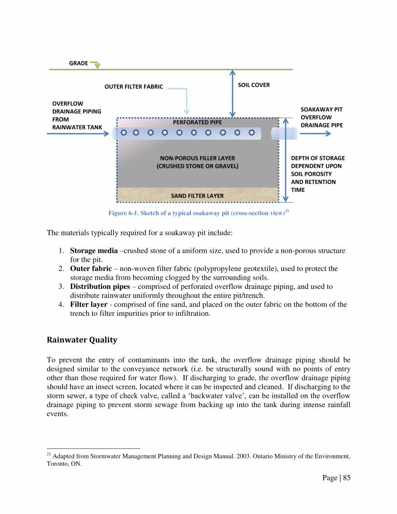
Page | 85
Figure 6-1. Sketch of a typical soakaway pit (cross-section view)
21
The materials typically required for a soakaway pit include:
1. Storage media –crushed stone of a uniform size, used to provide a non-porous structure for the pit.
2. Outer fabric – non-woven filter fabric (polypropylene geotextile), used to protect the storage media from becoming clogged by the surrounding soils.
3. Distribution pipes – comprised of perforated overflow drainage piping, and used to distribute rainwater uniformly throughout the entire pit/trench.
4. Filter layer - comprised of fine sand, and placed on the outer fabric on the bottom of the trench to filter impurities prior to infiltration.
Rainwater Quality
To prevent the entry of contaminants into the tank, the overflow drainage piping should be designed similar to the conveyance network (i.e. be structurally sound with no points of entry other than those required for water flow). If discharging to grade, the overflow drainage piping should have an insect screen, located where it can be inspected and cleaned. If discharging to the storm sewer, a type of check valve, called a ‗backwater valve‘, can be installed on the overflow drainage piping to prevent storm sewage from backing up into the tank during intense rainfall events.
21 Adapted from Stormwater Management Planning and Design Manual. 2003. Ontario Ministry of the Environment, Toronto, ON.
GRADE
OVERFLOW
DRAINAGE PIPING
FROM
RAINWATER TANK
PERFORATED PIPE
SOIL COVER
DEPTH OF STORAGE
DEPENDENT UPON
SOIL POROSITY
AND RETENTION
TIME SAND FILTER LAYER
NON-POROUS FILLER LAYER
(CRUSHED STONE OR GRAVEL)
OUTER FILTER FABRIC
SOAKAWAY PIT
OVERFLOW
DRAINAGE PIPE

Page | 86
Rainwater Harvesting as Part of a Stormwater Management System
Installing a RWH system for the express purpose of reducing stormwater runoff is a relatively new concept in Canada. A RWH system cannot eliminate the need for other stormwater management systems; however, if rainwater is to be managed on-site, RWH can reduce the size or complexity of other lot-level infiltration systems. Similarly, if overflow is discharged to the storm sewer, the rainwater tank can be used in place of a holding tank for detention and controlled release. As shown in Figure 6-2, the bottom portion of the tank stores rainwater for later use, and the top portion of the tank temporarily detains the rainwater and releases it at a predetermined rate through control valves. Excess volumes from extreme events are discharged through the overflow drainage piping.
Figure 6-2. Schematic of RWH system with outflow controls and controlled release drainage piping for
stormwater management. (‘DETENTION’ is the volume of runoff to be slowly released to storm sewer. The remaining volume ‘RETENTION’ is used to supply rainwater to permitted fixtures
For further guidelines on sizing a rainwater storage tank for both detention and retention, refer to Appendix D.
Page | 87
6.4 Design & Installation Guidelines
Design and installation guidelines:
Note: refer to Section 6.2 Applicable Codes, Standards, and Guidelines for the specific provisions that apply when the term ―in accordance with applicable provincial codes and regulations‖ is used.
1. Determine the overflow discharge location and method:
a. Overflow discharge locations include: grade, storm sewer, or soakaway pit; b. Overflow discharge methods include: gravity flow or pump-assisted flow; c. Overflow by pump-assisted flow is not recommended; d. Consult the applicable provincial codes and regulations, municipal bylaws, and
local authorities regarding the permitted overflow discharge locations; e. Evaluate the feasibility of the overflow discharge locations:
i. Overflow to grade: 1. The overflow discharge location must be at a lower elevation than
the flood level rim of the tank for gravity flow to be feasible. ii. Overflow to storm sewer:
1. A storm sewer connection must be present at the site, 2. The overflow discharge location must be at a lower elevation than
the flood level rim of the tank for gravity flow to be feasible. iii. Overflow to soakaway pit:
1. The percolation rate of site soils must be sufficient to permit infiltration of rainwater overflows discharged into the soakaway pit (refer to Appendix D for guidelines on performing a site soil assessment and sizing soakaway pits).
2. Plan the layout of the overflow system: a. Plan route of overflow drainage piping from the tank to the overflow discharge
location (refer to Section 1.4 Design & Installation Guidelines for guidelines and applicable provincial codes and regulations regarding drainage piping);
b. Ensure that there are no buried service lines (gas, electricity, water, stormwater, wastewater, phone, or cable lines) in the area where digging will take place to accommodate buried overflow drainage piping by contacting the municipality and service providers.
3. Overflow pipes: a. Overflow drainage pipes:
i. Pipe material: 1. PVC SDR35 pipe (recommended), or ABS pipe, where 2. Pipe selected must be approved by applicable provincial codes and
industry standards (CSA, ASTM, etc.). ii. Pipe size and slope:
1. Overflow drainage piping shall be sized to ensure that the capacity of overflow drainage pipe(s) are no less than the capacity of the rainwater conveyance drainage pipe(s),
2. Ensure a minimum slope of 0.5-2% (the greater the slope the better) is maintained throughout the pipe length,

Page | 88
iii. Tank connection: 1. Overflow drainage piping shall exit the tank at a height no lower
than that of the rainwater conveyance drainage piping, or ideally, at a height 50 mm [2 in.] below the bottom of the conveyance drainage pipe(s) entering the tank.
iv. Consult the applicable provincial codes and regulations pertaining to the installation of drainage piping (refer to Section 1.2 Applicable Codes,
Standards, and Guidelines for details). b. Overflow pressure pipes:
i. Pipe material: 1. Polyethylene pipe (recommended), where 2. Pipe selected must be approved by applicable provincial codes and
industry standards (CSA, ASTM, etc.). ii. Pipe size and slope:
1. Overflow pressure piping shall be sized to ensure that the capacity of overflow pressure pipe(s) are no less than the capacity of the rainwater conveyance drainage pipe(s).
iii. Consult the applicable provincial codes and regulations pertaining to the installation of pressure piping (refer to Section 5.2 Applicable Codes,
Standards, and Guidelines for details). 4. Discharging overflows to grade:
a. Overflows must be discharged in a location where rainwater won‘t pond or collect around building foundations;
b. Erosion prevention measures should be taken; c. A screen should be installed where the pipe terminates to prevent the entry of
birds, rodents or insects. 5. Discharging overflows to storm sewer:
a. Overflow drainage piping cannot be directly connected to a storm sewer, unless approved by local authorities;
b. A direct connection may be permitted if a backwater valve is installed on the overflow drainage pipe. Consult local authorities for approval;
c. An indirect connection can be made by overflowing: i. To an interceptor tank, which then overflows to storm sewer,
ii. To a soakaway pit, which then overflows to the storm sewer, iii. Via overland flow to a sewer grate, or iv. Using an air gap, in the case of above ground tanks.
6. Discharging overflows to a soakaway pit: a. Consult applicable provincial and municipal guidelines regarding the design and
installation of soakaway pits; b. For guidance purposes only, soakaway pit design and installation guidelines are
provided in Appendix D; c. If there is limited space for a soakaway pit or if the soil has a low permeability, it
is recommended that the soakaway pit have its own overflow, discharging overflows to grade or storm sewer.

Page | 89
7. Overflow discharge pump: a. If rainwater overflows must be pumped, the pump shall be sized to handle the
capacity of the rainwater conveyance drainage pipe(s); b. The pump shall be selected and installed in accordance with the guidelines
provided in Chapter 5. Pump and Pressurized Distribution System. 8. Incorporating a RWH system as part of a stormwater management system:
a. Consult the municipality and/or conservation authority regarding how to incorporate a RWH system into other stormwater management systems;
b. If considering utilizing a rainwater storage tank for both retention and detention purposes, refer to Appendix D for further details.
Page | 90
6.5 Management Guidelines
1. If the overflow drainage piping discharges above grade, it should be inspected annually:
a. The point at which the overflows discharge should be examined for signs of erosion. A splash pad or several small rocks can be placed at the discharge point to protect the area from future damage;
b. The coarse screen at the end of the overflow drainage pipe should be inspected for dirt and debris, and if necessary, be cleaned and/or replaced;
c. If removing the coarse screen for cleaning or replacement, the inside of the overflow drainage pipe should be inspected for objects or debris that may cause clogging.
2. If the overflow drainage piping discharges below grade, inspection and/or repair is only necessary when signs of a blocked or poor performing overflow-handling system are observed, such as:
a. Signs of water damage to the rainwater tank, tank lid or access hatch, or components located inside the tank above the maximum water level,
b. Signs of water leaking from the tank lid or access hatch, c. Signs of water backing up rainwater inlet lines and top-up drainage piping, or d. Signs of water leaking from downspout-to-conveyance drainage pipe transitions,
or leaking from top-up system air-gap. 3. If any of the above signs are observed, the components of the overflow system should be
inspected and repaired: a. Inspect coarse screens located on the overflow drainage pipe for debris that would
impede water flow, and clean, repair or replace the coarse screen as necessary; b. Inspect all overflow drainage pipes using a pipe scope for signs of blockages or
pipe damage. All debris/blockages should be removed from the overflow drainage piping, and all damaged sections of pipe must be replaced;
c. If problems with the overflow system take place during periods of freezing temperatures, it may be necessary to winterize the overflow drainage piping using the methods provided in Chapter 1. Rainwater Catchment & Conveyance;
d. If the overflow drainage piping discharges into a soakaway pit, the pit may be clogged with dirt and debris and may not be providing sufficient infiltration capacity. It may be necessary to repair and/or expand the pit to accommodate overflow volumes;
e. If there are no obvious problems with the overflow system, it may be necessary to simulate an overflow event (or observe one during a rainfall event). Monitor the system visually or by pipe scope to determine what is causing the problem.
4. While inspecting, cleaning, or repairing components of the overflow system, follow all necessary safety precautions, including Part 5 Confined Spaces of the Alberta Occupational Health & Safety Code if entry into the rainwater storage tank is required (see Chapter 2. Rainwater Storage & Tank Sizing for details).

Page | 91
Appendix
Appendix A. Rainwater Catchment & Conveyance
Collection Losses from Roof Surfaces
Sizing Gutters and Downspouts
Sizing Rainwater Conveyance Drainage Piping
Frost Penetration Depth & Pipe Freeze Protection
Appendix B. Rainwater Storage & Tank Sizing
Rainwater Harvesting Design Tool
Rainwater Storage Tank Sizing Table
Appendix C. Pump and Pressurized Distribution System
Calculation of Required Pump Capacity
Calculation of Required Pressure from Pump (Pump Head)
Calculation of Friction Loss
Calculation of Pressure Tank Size
Calculation of Pipe Size
Appendix D. Overflow Provisions & Stormwater Management
Utilizing a Rainwater Storage Tank for Retention &
Detention for Stormwater Management Purposes
Design & Sizing of Soakaway Pits
Assessment of Site Soil Infiltration Loading Rate
(Percolation Rate)

Page | 92
Appendix A. Rainwater Catchment & Conveyance
Collection Losses from Roof Surfaces
Although 1 L of runoff can theoretically be collected from each millimetre of rainfall contacting a 1 m2 area, some losses take place following contact with the catchment surface. These losses vary depending upon the type of catchment material and the geometry of the roof and should be considered when estimating the amount of rainwater that can be collected by the RWH system. Losses for various roof catchment materials are listed in Table A-1.
Table A-1. Collection efficiency (loss factors) associated with various roof catchments22, 23
Roof Catchment Material Initial Rainfall
Loss Factor (mm)
Continuous Rainfall
Loss Ratio (%)
Steel Roof 0.25 20.0
Asphalt Shingle Roof 0.5 20.0
Fiberglass Roof 0.5 20.0
Asphalt Built-up Flat Roof 1.5 20.0
Hypalon (Rubber) Flat Roof 1.5 20.0
Sizing Gutters and Downspouts
Note: the guidelines for sizing gutters and downspouts provided in Section 1.4 Design &
Installation Guidelines are reproduced below to assist with following the example provided.
The detailed example is located following the reproduced guidelines.
1. To determine the size of gutter required for a given roof drainage area:
a. Consult the applicable provincial codes and regulations pertaining to the design rainfall intensity for the site location (refer to Section 1.2 Applicable Codes,
Standards, and Guidelines for details); b. Calculate the area of roof draining into the gutter:
Equation A-1
Where: Length = length of the gutter served by a downspout (m)
Width = distance from the eave to the ridge of the roof drainage area served (m)
22 DIN 1989-1:2001-10. DIN 1989 Rainwater Harvesting Systems - Part 1: Planning, Installation, Operation and Maintenance. 2002. Fachvereinigung Betriebs- und Regenwassernutzung e.V, fbr, Darmstadt, Germany 23 Building Capacity for Rainwater Harvesting in Ontario: Rainwater Quality and Performance of RWH Systems. 2008. Despins, C. M.Sc. Thesis, University of Guelph.

Page | 93
c. Refer to Table A-2 to determine the minimum size of gutter, required based upon
the roof drainage area (m2) and design rainfall intensity values determined above:
Table A-2. Minimum gutter sizes for given roof drainage areas and rainfall intensities24
Minimum Required
Gutter Size and Type
Maximum Roof Drainage Area Served per Downspout (m2)1,2
Design Rainfall Intensity (15 Min rainfall, mm):
18.75 25 31.25 37.5 43.75 50 56.25 62.5
100 mm [4 in.] K-style 71 53 43 35 30 27 24 21
125 mm [5 in.] K-style 130 98 78 65 56 49 43 39
150 mm [6 in.] K-style 212 159 127 106 91 79 71 64 1
Minimum required gutter size assumes that gutte s ha e a i i u slope ≤ . % . Fo g eate gutter slopes, the table values may be multiplied by 1.1. 2 Ma i u oof d ai age a ea assu ed oof slopes ≤ : . Fo steepe oof pit hes, ultipl the ta le
values by 0.85.
d. For other gutter types and/or larger roof drainage areas, consult the gutter
manufacturer or contractor regarding the sizing of gutter. 2. To determine the size of downspout required:
a. Refer to Table A-5 to determine the minimum size of downspout (either rectangular- or square type) based upon the size of gutter the downspout is serving:
Table A-3. Minimum downspout sizes for given size of gutter25
Gutter Size and Type
Minimum Downspout Size
( mm [in] )
Rectangular type Square-type
100 mm [4 in.] K-style 50x75 [2x3 ] 75x75 [3x3]
125 mm [5 in.] K-style 50x75 [2x3] 75x75 [3x3]
150 mm [6 in.] K-style 75 x 100 [3x4] 100x100 [4x4]
b. For other downspout types and/or larger gutter sizes, consult the gutter/downspout
manufacturer or contractor regarding the sizing of downspout.
24 Adapted from Moisture Resistant Homes: A Best Practice Guide and Plan Review Tool for Builders and Designers. 2006. U.S. Department of Housing and Urban Development, Washington, DC. 25 Adapted from Moisture Resistant Homes: A Best Practice Guide and Plan Review Tool for Builders and Designers. 2006. U.S. Department of Housing and Urban Development, Washington, DC.

Page | 94
3. Example: For a residential house located in Edmonton, AB with a roof with the peaks and roof pitch illustrated in Figure A-1 and Figure A-2:
Figure A-1. Roof drainage area to be guttered (isometric ‘facing’ view)26
Figure A-2. Roof drainage area to be guttered (projected ‘top-down’ view)27
26 Adapted from Moisture Resistant Homes: A Best Practice Guide and Plan Review Tool for Builders and Designers. 2006. U.S. Department of Housing and Urban Development, Washington, DC. 27 Adapted from Moisture Resistant Homes: A Best Practice Guide and Plan Review Tool for Builders and Designers. 2006. U.S. Department of Housing and Urban Development, Washington, DC.
9 m 4 m
6 m 9 m
Roof pitch 5:12
1
2
10 m
4.5 m
4 m
4.5 m
Rainwater storage
tank location
(below-ground tank) Ideal downspout
location
Additional
downspout location
(if small gutter used)

Page | 95
From the Alberta Building Code 2006 Division B , Appendix C - Table C-2 (refer to Section 1.2
Applicable Codes, Standards, and Guidelines for details):
Design rainfall intensity (15 Min rainfall, mm): 23 To calculate the roof drainage area:
Referring to Table A-2 (reproduced from Table 1-3), the maximum roof drainage area for this section of roof is given in the second column (23 mm rainfall intensity for the City of Edmonton – rounded up to 25 mm). To discharge the entire roof drainage area to one downspout:
Referring to the second column of Table A-2, a 100 mm [4 in.] K-style gutter can only be used to convey rainwater from roof areas of up to 53 m2. This area, however, is less than the drainage area calculated for this residential household – 63 m2. By selecting a larger gutter – a 125 mm [5 in.] K-style gutter – all of the drainage area can be discharged to one downspout as this gutter size can convey rainwater from an area of up to 78 m2 (> 63 m2). Referring to Table A-3 (reproduced from Table 1-4), a 125 mm [5 in.] K-style gutter requires a 50x75 mm [2x3 in.] rectangular-type downspout, or a 75x75 mm [3x3 in.] square-type downspout. To minimize the length of conveyance drainage piping required, the downspout should be located as close as possible to the rainwater storage tank. The ideal location of the downspout is illustrated in Figure A-2.

Page | 96
To discharge the roof drainage area to more than one downspout:
Referring to the second column of Table A-2, a 100 mm [4 in.] K-style gutter can be used – but additional downspouts are required because the roof drainage area considered is greater than the maximum roof drainage area served per downspout (by one downspout). To calculate the number of downspouts required: By selecting a smaller gutter – a 100 mm [4 in.] K-style gutter – the drainage area must be discharged to 1.2 downspouts (rounded up to 2 downspouts). Referring to Table A-3 (reproduced from Table 1-4), a 100 mm [4 in.] K-style gutter requires a 50x75 mm [2x3 in.] rectangular-type downspout, or a 75x75 mm [3x3 in.] square-type downspout. In addition to the one downspout located close to the rainwater storage tank (shown in Figure A-2 as the ‗ideal downspout location‘), a second downspout is required. Locating downspouts on interior building corners is not recommended, thus, it should be placed at the corner closest to the rainwater storage tank (see Figure A-2).
Sizing Rainwater Conveyance Drainage Piping
1. Table A-4 and Table A-5 can be used to estimate the size of conveyance drainage pipes
for different catchment areas:

Page | 97
Table A-4. Conveyance drainage pipe size requirements for roof areas 50-950 m2 in Alberta cities
28
City Roof Area (m2)
0 50 100 150 200 250 300 350 400 450 500 550 600 650 700 750 800 850 900 950
Lethbridge 4 6 8
Medicine Hat 4 6 8
Calgary 4 6 8
Banff 4 6 8
Drumheller 4 6 8
Red Deer 4 6 8
Camrose 4 6 8
Edmonton 4 6 8
Jasper 4 6
Lloydminster 4 6 8
Slave Lake 4 6 8
Grande Prarie 4 6 8
Fort McMurray 4 6
Legend
4" Pipe
6" Pipe
8" Pipe
10" Pipe
12" Pipe
15" Pipe
28 Adapted from Alberta Building Code. 2006. Alberta Ministry of Municipal Affairs, Edmonton, AB. Adapted from National Plumbing Code of Canada. 2005. National Research Council of Canada, Ottawa, Ontario. Assumes 1% pipe slope.

Page | 98
Table A-5. Conveyance drainage pipe size requirements for roof areas 1000-3000 m2 in Alberta cities
29
City Roof Area (m2)
1000 1100 1200 1300 1400 1500 1600 1700 1800 1900 2000 2100 2200 2300 2400 2500 2600 2700 2800 2900
Lethbridge 8 10 12
Medicine Hat 8 10 12
Calgary 8 10 12
Banff 8 10 12
Drumheller 8 10 12
Red Deer 8 10 12
Camrose 8 10 12
Edmonton 8 10 12
Jasper 6 8 10
Lloydminster 8 10 12
Slave Lake 8 10
Grande Prarie 8 10 12
Fort McMurray 8 10
Legend
4" Pipe
6" Pipe
8" Pipe
10" Pipe
12" Pipe
15" Pipe
29 Adapted from Alberta Building Code. 2006. Alberta Ministry of Municipal Affairs, Edmonton, AB. Adapted from National Plumbing Code of Canada. 2005. National Research Council of Canada, Ottawa, Ontario. Assumes 1% pipe slope.

Page | 99
Frost Penetration Depth & Pipe Freeze Protection
1. Local frost penetration depths for can be estimated using the following method:
a. Locate the site on the map in Figure A-3 and identify the nearest contour line and its associated freezing index value (given in degree days);
b. Estimate the frost penetration depth by correlating the degree-day value from Figure A-3 to the corresponding depth in Table A-6:
Figure A-3. Normal freezing index for Canada in degree days
30
30 Adapted from Canada Normal Freezing Index in Degree Days, Period 1931-1960. Environment Canada, Ottawa, ON.

Page | 100
Table A-6. Approximate frost depths associated with various freezing index values31
Freezing Index
(Degree Days)
Frost Depth
(m)
Freezing Index
(Degree Days)
Frost Depth
(m)
400 0.66 2000 1.98
450 0.71 2050 2.01
500 0.76 2100 2.04
550 0.81 2150 2.07
600 0.86 2200 2.1
650 0.91 2250 2.13
700 0.96 2300 2.16
750 1 2350 2.19
800 1.05 2400 2.22
850 1.09 2450 2.25
900 1.14 2500 2.28
950 1.18 2550 2.31
1000 1.21 2600 2.34
1050 1.25 2650 2.36
1100 1.29 2700 2.39
1150 1.32 2750 2.42
1200 1.36 2800 2.45
1250 1.39 2850 2.48
1300 1.43 2900 2.51
1350 1.47 2950 2.52
1400 1.5 3000 2.54
1450 1.54 3050 2.56
1500 1.57 3100 2.59
1550 1.62 3150 2.62
1600 1.66 3200 2.64
1650 1.7 3250 2.67
1700 1.74 3300 2.69
1750 1.78 3350 2.72
1800 1.82 3400 2.74
1850 1.86 3450 2.77
1900 1.9 3500 2.79
1950 1.94 4000 2.8
31 Adapted from Ambient Temperatures – Below Ground (Frost Depth). 2009. Urecon Ltd., St. Lazare-de-Vaudreuil, Quebec.

Page | 101
2. To plan the layout of conveyance drainage piping for rainwater storage tanks located
below grade: a. Determine the location of the tank (refer to Chapter 2. Rainwater Storage & Tank
Sizing for guidance); b. Determine the frost penetration depth by consulting local building authorities
regarding regulations or ‗rules of thumb‘ for frost penetration depths. For estimation purposes, refer to the above methods in Appendix A;
c. Where possible, rainwater conveyance drainage pipes and the storage tank should be buried below the frost penetration depth, otherwise additional freeze protection measures, such as insulation shall be required;
d. To determine if the conveyance drainage pipes can be buried below the frost penetration depth:
i. Determine the final pipe burial depth (Df), where this depth depends upon: 1. The local frost penetration depth, and 2. The maximum rated burial depth of the rainwater storage tank, 3. Where Df shall be the lesser of the two values (i.e., if the tank
cannot be buried below the frost penetration depth due to tank burial depth restrictions, then Df shall be equal to the tank‘s max. rated burial depth).
ii. Determine the initial pipe burial depth (Di), where this depth depends upon:
1. The total length of pipe, 2. The slope of pipe, and 3. The site grading, 4. Where Di can be determined using Figure A-4 and Equation A-2:
Figure A-4. Pipe conveyance (profile view)
1. ROOF CATCHMENT
Di
6. RAINWATER STORAGE TANK
L
Sp
Sg
(-)Sg
2. GUTTER
3. DOWNSPOUT
4. DOWNSPOUT TO
PIPE TRANSITION
5. CONVEYANCE DRAINAGE PIPE
Df

Page | 102
Equation A-2
Where: Di = Initial pipe burial depth (m) Df = Final pipe burial depth (m) Lp = Length of pipe (m) Lg = Length of pipe for which there is a grade change (m) Sp = Pipe slope factor (0.01 recommended) Sg = Grade slope factor, assumes downward slope
iii. If Df and/or Di is less than the frost penetration depth, then there is a risk
of rainwater freezing in the conveyance network. In such cases, repeat the above process, while considering the following:
1. Locate the tank in an area with the lowest elevation at the site, 2. Minimize the distance between the furthest downspout and the
tank (decrease the horizontal travel distance, H), 3. Increase the burial depth of the tank (ensure that the tank is rated to
handle increased burial depth), and/or 4. Reduce the pipe slope to a minimum of 0.5-1%.
iv. If the conveyance drainage pipe cannot be maintained at or near frost penetration depth, consider insulating pipe (refer to the method below), or alternatively, install heat tracing for use during periods of extreme cold.
3. If burial below the frost penetration depth is not feasible, the pipe should be insulated: a. Figure A-5 and Equation A-3 can be used to estimate the width of insulation
required:
Figure A-5. Frost protection of pipe by horizontal insulation
32
32 Adapted from Ontario‘s Building Code. 2006. Ministry of Municipal Affairs and Housing, Toronto, ON.

Page | 103
[ ]
Equation A-333
Where:
W = width of insulation (m) D = outside diameter of pipe (m) X = insulation depth (m) F = estimated frost depth (m)
b. The thickness of the insulation can be estimated using Table A-7:
Table A-7. Thickness of foam insulation given various pipe burial (backfill) depths34
Thickness of Foam Insulation (mm)
Frost Depth
Amount
of Backfill
over the
Insulation
1.1 m 1.3 m 1.5 m 1.7 m 1.9 m 2.1 m 2.3 m
≤ 0.6 m 50 65 75 90 100 115 125
≤ 0.9 m 40 50 65 75 90 100 115
≤ 1.2 m 25 40 50 65 75 90 100
≤ 1.5 m 25 40 50 65 75 90
≤ 1.8 m 40 50 65 75
≤ 2.1 m 40 50 65
33 Adapted from Ontario‘s Building Code. 2006. Ministry of Municipal Affairs and Housing, Toronto, ON. 34 Adapted from Ontario‘s Building Code. 2006. Ministry of Municipal Affairs and Housing, Toronto, ON, and Canada Normal Freezing Index in Degree Days, Period 1931-1960. Environment Canada, Ottawa, ON.
Page | 104
Appendix B. Rainwater Storage & Tank Sizing Note: Some of the fixtures listed in this Appendix may not be permitted by the applicable
provincial codes and regulations. Data and examples referencing such fixtures are provided for
illustration purposes only.
Rainwater Harvesting Design Tool
1. Rainwater storage tanks can be sized using the Rainwater Harvesting System Design
Tool, which can be accessed on-line; 2. Instructions on the use of the Rainwater Harvesting System Design Tool are provided
with the Design Tool software package. Refer to these instructions for further details.
Rainwater Storage Tank Sizing Table
1. Rainwater storage tanks can be sized using Table B-3, which was developed using the
Rainwater Harvesting System Design Tool. Note: Table B-3 summarizes results from the
tool for the City of Edmonton, but these tank sizes should be applicable for much of
Alberta. In regions where there is less annual rainfall than Edmonton, tanks with larger
storage capacities than those listed in Table B-3 are recommended. 2. Household indoor rainwater demand can be estimated using Table B-1 and the following
instructions: a. For each fixture to be supplied with rainwater, determine the fixture type and
associated water usage by examining the fixture and/or referring to the manufacturer‘s product literature;
b. Once the fixture type and water usage have been determined, calculate the daily rainwater usage for the fixture by multiplying the water usage (provided by the manufacturer, or using the average figures provided in Table B-1) by the number of uses per person per day (provided in Table B-1). Multiply the resulting figure by the number of occupants residing within the household;
c. Sum these values to determine the total indoor rainwater demand (Litres per day); d. Sum the total indoor rainwater demand with the total outdoor rainwater demand,
where applicable (refer to Table B-2 and the accompanying instructions for assistance on calculating outdoor rainwater usage);

Page | 105
Table B-1. Household indoor fixtures and associated water usage figures/assumptions35
Fixtures Fixture Type Water Usage
Number of Uses
Per Person Per
Day
Water Usage
Duration
Toilet Low flush 13.0 Litres/flush 5 -
Toilet Ultra-low flush 6.0 Litres/flush 5 -
Toilet Dual flush/HET 4.8 Litres/flush 5 -
Laundry Top loading 150 Litres/load 0.37 -
Laundry Front loading 100 Litres/load 0.37 -
Lavatory Inefficient/old 8.0 Litres/minute 3 0.5 minutes
Lavatory Standard 5.3 Litres/minute 3 0.5 minutes
Lavatory High-efficiency 3.2 Litres/minute 3 0.5 minutes
Shower Inefficient/old 9.5 Litres/minute 0.3 5 minutes
Shower Standard 8.3 Litres/minute 0.3 5 minutes
Shower High-efficiency 5.7 Litres/minute 0.3 5 minutes
e. Example: For a household of five, using rainwater for toilet flushing and laundry: - The toilets in the home are the ultra-low flush 6.0 Litre per flush type. - The washing machine is a typical top-loading machine using 150 Litres per load. Daily rainwater demand (Toilets) = 6.0 Litres/flush × 5 flushes per person per
day × 5 persons
Daily rainwater demand (Toilets) = 150 Litres/day
Daily Indoor Rainwater Demand (Total) = 150 Litres/day
3. Household outdoor rainwater demand can be estimated using Table B-2and the following instructions:
a. For each fixture to be supplied with rainwater, determine the fixture type and associated water usage by examining the fixture and/or referring to the manufacturer‘s product literature;
b. Once the fixture type and water usage have been determined, calculate the weekly rainwater usage:
i. For the garden hose by multiplying the water usage (provided by the manufacturer, or using the average figures provided in Table B-2) by the number of uses per week and multiplying the resulting figure by the water usage duration (provided in Table B-2),
ii. For the irrigation system by multiplying the water usage (provided by the manufacturer, or using the average figures provided in Table B-2) by the
35 Adapted from: Vickers, A. 2001. Handbook of Water Use and Conservation. Water Plow Press. Amherst, MA.
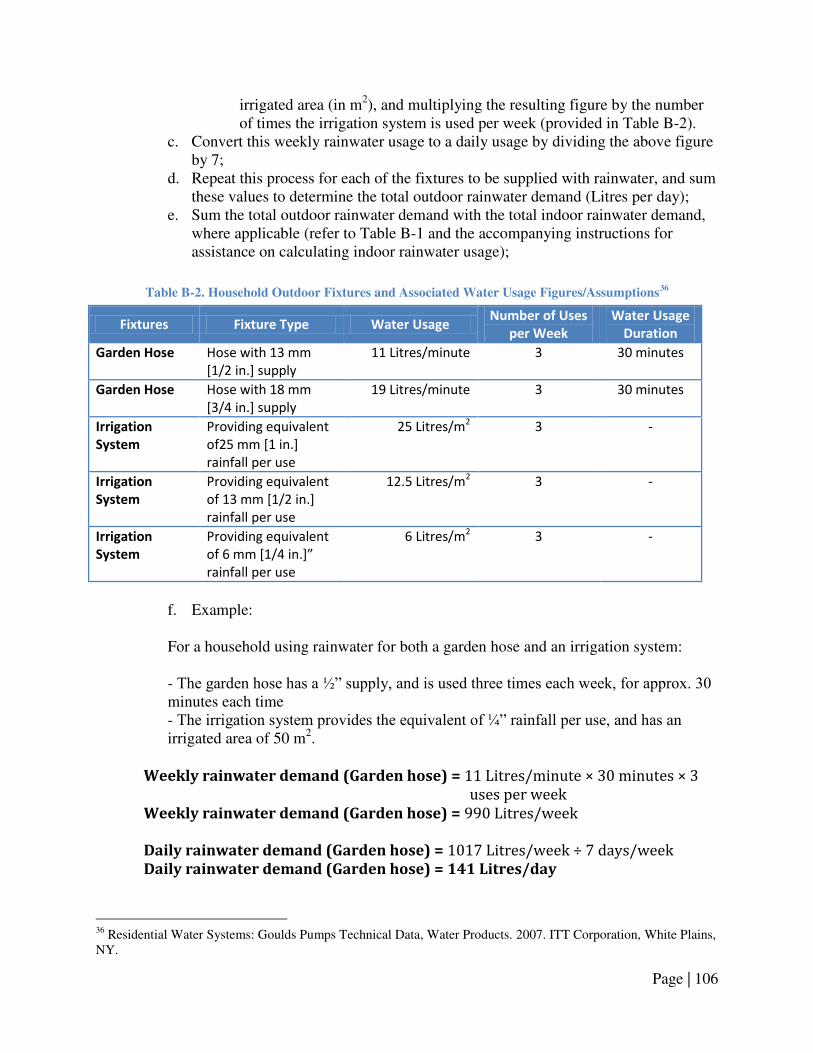
Page | 106
irrigated area (in m2), and multiplying the resulting figure by the number of times the irrigation system is used per week (provided in Table B-2).
c. Convert this weekly rainwater usage to a daily usage by dividing the above figure by 7;
d. Repeat this process for each of the fixtures to be supplied with rainwater, and sum these values to determine the total outdoor rainwater demand (Litres per day);
e. Sum the total outdoor rainwater demand with the total indoor rainwater demand, where applicable (refer to Table B-1 and the accompanying instructions for assistance on calculating indoor rainwater usage);
Table B-2. Household Outdoor Fixtures and Associated Water Usage Figures/Assumptions36
Fixtures Fixture Type Water Usage Number of Uses
per Week
Water Usage
Duration
Garden Hose Hose with 13 mm
[1/2 in.] supply
11 Litres/minute 3 30 minutes
Garden Hose Hose with 18 mm
[3/4 in.] supply
19 Litres/minute 3 30 minutes
Irrigation
System
Providing equivalent
of25 mm [1 in.]
rainfall per use
25 Litres/m2 3 -
Irrigation
System
Providing equivalent
of 13 mm [1/2 in.]
rainfall per use
12.5 Litres/m2 3 -
Irrigation
System
Providing equivalent
of 6 mm [1/4 in.] rainfall per use
6 Litres/m2 3 -
f. Example: For a household using rainwater for both a garden hose and an irrigation system: - The garden hose has a ½‖ supply, and is used three times each week, for approx. 30 minutes each time - The irrigation system provides the equivalent of ¼‖ rainfall per use, and has an irrigated area of 50 m2.
Weekly rainwater demand (Garden hose) = 11 Litres/minute × 30 minutes × 3
uses per week
Weekly rainwater demand (Garden hose) = 990 Litres/week
Daily rainwater demand (Garden hose) = 1017 Litres/week ÷ 7 days/week
Daily rainwater demand (Garden hose) = 141 Litres/day
36 Residential Water Systems: Goulds Pumps Technical Data, Water Products. 2007. ITT Corporation, White Plains, NY.

Page | 107
Weekly rainwater demand (Irrigation System) = 6 Litres/m2 × 50 m2 irrigated
area × 3 uses per week
Weekly rainwater demand (Irrigation System) = 900 Litres/week
Daily rainwater demand (Irrigation System) = 900 Litres/week ÷ 7 days/week
Daily rainwater demand (Irrigation System) = 129 Litres/day
Daily Outdoor Rainwater Demand (Total) = 141 Litres/day + 129 Litres/day
Daily Outdoor Rainwater Demand (Total) = 270 Litres/day
4. Calculate the daily rainwater demand (Litres per day) by summing the household indoor rainwater demand and the outdoor rainwater demand;
a. Example:
Summing indoor & outdoor demand:
Daily Rainwater Demand (Total) = 150 Litres/day + 270 Litres/day
Daily Rainwater Demand (Total) = 420 Litres/day
5. Refer to Table B-3 to find the recommended tank size using the daily rainwater demand (Litres per day) and the roof catchment area (m2);
6. Note: How were Table B-3 recommended storage volumes determined? a. For each unique combination of daily rainwater demand and roof catchment area
(i.e., for a RWH system with a daily rainwater demand of 50 Litres/day and a roof catchment area of 100 m2) rainwater storage tanks of increasing storage capacities were modelled using the Rainwater Harvesting Design Tool;
b. While comparing the multiple tanks, if a tank with a larger storage capacity provided a significant increase in the water savings provided by the RWH system, when compared against a smaller tank, the Design Tool recommended the larger tank.
c. This process was repeated with increasing storage tank volumes until the water savings increase provided by the larger tank was considered to be insignificant;
d. The criteria that was used to distinguish between a significant and insignificant was as follows:
i. If larger tank provides ≥ 2.5% increase in water savings per 1,000 Litres, select larger tank and continue process to examine the water savings of subsequent larger tanks;
ii. If larger tank provides < 2.5% increase in water savings per 1,000 Litres, do not consider the tank, and recommend the largest storage tank that met the ≥ 2.5% criteria.

Page | 108
Table B-3. Recommended storage tank capacities for catchment areas and rainwater demands for RWH systems located in Edmonton, Alberta
Daily
Rainwater
Demand
(Litres per
day)
Optimum Rainwater Storage Tank Cistern Capacity (L)
Roof Catchment Area (m2)
50 100 150 200 250 300 350 400 450 500 600 700 800 900 1,000 1,500 2,000 2,500 3,000
50 2,000 2,000 2,000 2,000 2,000 2,000 2,000 2,000 2,000 2,000 2,000 2,000 2,000 2,000 5,000 5,000 5,000 5,000 5,000
100 2,000 4,000 4,000 4,000 4,000 4,000 4,000 4,000 4,000 4,000 4,000 4,000 4,000 4,000 5,000 5,000 5,000 5,000 5,000
150 2,000 4,000 4,000 4,000 4,000 5,000 5,000 5,000 5,000 5,000 5,000 5,000 5,000 5,000 5,000 5,000 5,000 5,000 5,000
200 2,000 4,000 4,000 4,000 4,000 5,000 5,000 5,000 7,500 7,500 7,500 7,500 7,500 7,500 7,500 7,500 7,500 7,500 7,500
250 - 4,000 4,000 4,000 4,000 5,000 5,000 5,000 7,500 7,500 7,500 7,500 7,500 7,500 7,500 7,500 7,500 7,500 7,500
300 - 4,000 4,000 4,000 4,000 5,000 5,000 5,000 7,500 7,500 7,500 10,000 10,000 10,000 10,000 10,000 10,000 10,000 10,000
350 - 4,000 4,000 4,000 4,000 5,000 5,000 5,000 7,500 7,500 7,500 10,000 10,000 10,000 10,000 10,000 10,000 10,000 10,000
400 - 4,000 4,000 4,000 4,000 5,000 5,000 5,000 7,500 7,500 7,500 10,000 10,000 10,000 10,000 10,000 10,000 10,000 10,000
450 - 4,000 4,000 4,000 4,000 5,000 5,000 5,000 7,500 7,500 7,500 10,000 10,000 10,000 10,000 10,000 10,000 10,000 10,000
500 - - 4,000 4,000 4,000 5,000 5,000 5,000 7,500 7,500 7,500 10,000 10,000 10,000 10,000 15,000 15,000 15,000 15,000
600 - - 4,000 4,000 4,000 5,000 5,000 5,000 7,500 7,500 7,500 10,000 10,000 10,000 10,000 15,000 15,000 15,000 15,000
700 - - 4,000 4,000 4,000 5,000 5,000 5,000 7,500 7,500 7,500 10,000 10,000 10,000 10,000 15,000 15,000 15,000 15,000
800 - - 4,000 4,000 4,000 5,000 5,000 5,000 7,500 7,500 7,500 10,000 10,000 10,000 10,000 15,000 15,000 15,000 15,000
900 - - 4,000 4,000 4,000 5,000 5,000 5,000 7,500 7,500 7,500 10,000 10,000 10,000 10,000 15,000 15,000 15,000 15,000
1,000 - - 4,000 4,000 4,000 5,000 5,000 5,000 7,500 7,500 7,500 10,000 10,000 10,000 10,000 15,000 15,000 15,000 15,000
1,500 - - - - 4,000 5,000 5,000 5,000 7,500 7,500 7,500 10,000 10,000 10,000 10,000 15,000 15,000 15,000 15,000
2,000 - - - - - 5,000 5,000 5,000 7,500 7,500 7,500 10,000 10,000 10,000 10,000 15,000 15,000 15,000 15,000
2,500 - - - - - - - 5,000 7,500 7,500 7,500 10,000 10,000 10,000 10,000 15,000 15,000 15,000 15,000
3,000 - - - - - - - - - 7,500 7,500 10,000 10,000 10,000 10,000 15,000 15,000 15,000 15,000
Recommended rainwater storage tank capacities generated using the Rainwater Harvesting System Design Tool assuming:
1. Historical rainfall for the City of Edmonton, from 1961-2005 (median annual rainfall 346 mm);
2. Opti u ai ate sto age ta k apa it alues i lude a assu ptio of a % u used olu e t pi all efe ed to as dead spa e .
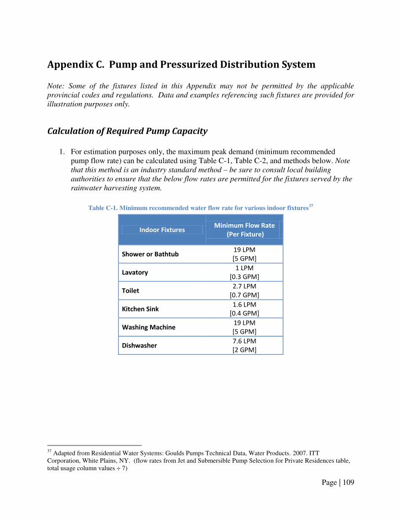
Page | 109
Appendix C. Pump and Pressurized Distribution System Note: Some of the fixtures listed in this Appendix may not be permitted by the applicable
provincial codes and regulations. Data and examples referencing such fixtures are provided for
illustration purposes only.
Calculation of Required Pump Capacity
1. For estimation purposes only, the maximum peak demand (minimum recommended
pump flow rate) can be calculated using Table C-1, Table C-2, and methods below. Note
that this method is an industry standard method – be sure to consult local building
authorities to ensure that the below flow rates are permitted for the fixtures served by the
rainwater harvesting system.
Table C-1. Minimum recommended water flow rate for various indoor fixtures37
Indoor Fixtures Minimum Flow Rate
(Per Fixture)
Shower or Bathtub 19 LPM
[5 GPM]
Lavatory 1 LPM
[0.3 GPM]
Toilet 2.7 LPM
[0.7 GPM]
Kitchen Sink 1.6 LPM
[0.4 GPM]
Washing Machine 19 LPM
[5 GPM]
Dishwasher 7.6 LPM
[2 GPM]
37 Adapted from Residential Water Systems: Goulds Pumps Technical Data, Water Products. 2007. ITT Corporation, White Plains, NY. (flow rates from Jet and Submersible Pump Selection for Private Residences table, total usage column values ÷ 7)

Page | 110
Table C-2. Minimum recommended water flow rate for various outdoor fixtures38
Outdoor Fixtures Minimum Flow Rate
(Per Fixture)
Garden hose with 13 mm
[1/2 in.] supply
11 LPM
[3 GPM]
Garden hose with 18 mm
[3/4 in.] supply
19 LPM
[6 GPM]
Irrigation system
Varies
(Consult supplier/
contractor)
2. Example:
Using Table C-1, if a given pump and pressure system must provide rainwater to three toilets, a washing machine and hose bib the maximum peak demand can be determined as follows:
Table C-3. Example calculation – sizing maximum peak demand
Indoor Fixtures Number of
Fixtures
Minimum Flow
Rate
(Per Fixture)
Total Flow
Rate
Toilet 3 2.7 LPM 8.1 LPM
Washing machine 1 19 LPM 19 LPM
Hose watering (1/2 in. supply) 1 11 LPM 11 LPM
Maximum peak demand 38 LPM
As shown in Table C-3, the total water usage is determined by multiplying the number of fixtures by the minimum flow rate for each fixture, and is summed for all types of fixtures to estimate the maximum peak demand. For the above application, a pump providing a minimum flow rate of 38 LPM [10 GPM] pump is recommended.
38 Adapted from Residential Water Systems: Goulds Pumps Technical Data, Water Products. 2007. ITT Corporation, White Plains, NY. (flow rates from Yard Fixtures table)

Page | 111
Calculation of Required Pressure from Pump (Pump Head)
1. The pump head can be calculated using the following equations:
a. Pump Head (m, or ft) = Required System Pressure + Total Dynamic Head
Where: Required System Pressure is the operating pressure required for the rainwater fixtures (275-415 kPa [~40-60 psi] for typical residential applications). Pressure can be converted from kPa or psi to m or ft using Table C-4:
Table C-4. Conversion factors for ‘kPa’ and ‘psi’
Pressure (kPa) Pressure (psi)
Conversion to
Metres (m) Height (m) = ____ kPa x 0.10 Height (m) = ____ psi x 0.70
Conversion to Feet
(ft) Height (ft) = ____ kPa x 0.33 Height (ft) = ____ psi x 2.31
b. Total Dynamic Head (m, or ft) = Static Lift + Static Height + Friction Loss
Where: Static Lift is the height from the water level to the pump (applicable only for jet pumps), Static Height is the height from the pump to the furthest fixture, and Friction Loss can be calculated using the method provided below.

Page | 112
Calculation of Friction Loss
1. To calculate the Friction Loss component of the Total Dynamic Head:
a. Calculate the friction head losses that occur due to the flow rate and pipe sizes using Table C-5 (table values assume a SCH40 PVC pipe or similar material such as PE-polyethylene or PP-polypropylene is utilized):
Table C-5. Friction head losses for SCH40 PCV pipe at various flow rates39
Flow Rate, Q (LPM)
F100, Friction Head (m / 100 m pipe)
Pipe Diameter
13 mm [½ in.]
18 mm [¾ in.]
25 mm [1 in.]
32 mm [1 ¼ in.]
38 mm [1 ½ in.]
50 mm [2 in.]
8 4.8 1.2 0.38 0.1
19 25.8 6.3 1.9 0.5 0.2
30 63.7 15.2 4.6 1.2 0.6 0.2
38 97.5 26 6.9 1.8 0.8 0.3
57 49.7 14.6 3.8 1.7 0.5
76 86.9 25.1 6.4 2.9 0.9
113 13.6 6.3 1.8
b. Example:
Using Table C-5, for a pump generating a flow rate of 38 LPM [10 GPM], with a rainwater service pipe diameter of 32 mm [1 ¼ in.] and a rainwater supply pipe diameter of 18 mm [¾ in.]: F100-SE, Friction head (m /100 m pipe) = 1.8 m/ 100 m pipe-service pipe
F100-SU, Friction head (m /100 m pipe) = 26 m / 100 m of pipe-supply pipe
39 Adapted from Residential Water Systems: Goulds Pumps Technical Data, Water Products. 2007. ITT Corporation, White Plains, NY.

Page | 113
c. Calculate the friction head losses that occur due to the type of pipe fitting and
pipe size using Table C-6 (table values assume a SCH40 PVC pipe or similar material such as PE-polyethylene or PP-polypropylene is utilized).
Table C-6. Equivalent length of pipe for different fittings40
Fitting
Equivalent Length of Pipe (m)
Pipe Diameter
13 mm
[½ in.]
18 mm
[¾ in.]
25 mm
[1 in.]
32 mm
[1 ¼ in.]
38 mm
[1 ½ in.]
50 mm
[2 in.]
75 mm
[3 in.]
90° Elbow 0.5 0.6 0.8 1.1 1.3 1.7 2.4
45° Elbow 0.2 0.3 0.4 0.5 0.6 0.8 1.2
Gate Valve (shut-off
valve) (Open) 0.1 0.2 0.2 0.2 0.3 0.4 0.5
Tee Flow – Run 0.3 0.6 0.6 0.9 0.9 1.2 1.8
Tee Flow - Branch 1.0 1.4 1.7 2.3 2.7 3.7 5.2
In Line Check Valve
(Spring) or Foot Valve 1.2 1.8 2.4 3.7 4.3 5.8 9.8
90° Elbow 0.5 0.6 0.8 1.1 1.3 1.7 2.4
d. Example: Using Table C-6, for a pressure system with three 32 mm [1 ¼ in.] 90° elbows on the rainwater service piping, and five 18 mm [¾ in.] 90° elbows on the rainwater supply piping: LF-SE, Equivalent Length of Pipe (m) = 3 x 1.1
LF-SE, Equivalent Length of Pipe (m) = 3.3 m-service pipe
LF-SU, Equivalent Length of Pipe (m) = 5 x 0.6
LF-SU, Equivalent Length of Pipe (m) = 3.0 m-supply pipe e. To calculate the total friction head losses, Equation C-1 should be used:
[ ] [ ] Equation C-1
40 Adapted from Residential Water Systems: Goulds Pumps Technical Data, Water Products. 2007. ITT Corporation, White Plains, NY.

Page | 114
Where:
Friction Loss = Combined friction losses (m) for the service piping (SE) and supply piping (SU)
LP = Linear length of pipe (m) LF = Equivalent length of the pipe fittings (m) F100 = Friction loss per 100 m of pipe
f. Example:
Using the above equation, the losses for a pump and pressure system using the above pipe diameters and number of fittings, where the length of the rainwater service piping was 15 m and the rainwater supply piping was 10 m:
[ ] [ ] [ ] [ ]
[ ]
For the pump and pressure system described above, the friction loss is equivalent to 3.7 m of pipe, which can be used to calculate the Total Dynamic Head.
Calculation of Pressure Tank Size
1. To size a pressure tank that is compatible with a constant speed pump:
a. Use the following equation to calculate the required capacity for the pressure tank:
Equation C-2
Where: Pump flow rate (capacity) was determined above, Pump run time is provided by the pump manufacturer/supplier (typically, 1-2 minutes), and The drawdown factor can be determined using Table C-7:

Page | 115
Table C-7. Drawdown factors for various cut-in/cut-out pressures41
System Pressure
(Cut-in/Cut-out Pressure)
Drawdown
Factor
138/276 kPa [20/40 psi] 0.37
276/414 kPa [40/60 psi] 0.27
414/552 kPa [60/80 psi] 0.21
552/689 kPa [80/100 psi] 0.17
Calculation of Pipe Size
1. To determine the required pipe size diameter for the rainwater service piping and supply
piping, the following steps can be used for estimation purposes: a. For the service piping:
i. The diameter of the rainwater service pipe can be sized using the equation below (the equation assumes PVC or similar material such as PE-polyethylene or PP-polypropylene is utilized):
( )
Equation C-342
Where:
Q = the pump flow rate (LPM) F100 = the friction loss per 100 m of pipe (see following steps for details)
ii. Before this equation can be solved, however, the maximum permitted head
loss (F100-SE) must be set. A general rule of thumb is that this loss not exceed 5 m / 100 m pipe [5 ft / 100 ft pipe]43 , however the pump manufacturer/supplier should be contacted to confirm that these head losses will not impair pump performance or cause a loss of prime,
41 Adapted from Residential Water Systems: Goulds Pumps Technical Data, Water Products. 2007. ITT Corporation, White Plains, NY. 42 Adapted from Hazen-Williams Equation - Calculating Friction Head Loss in Water Pipes. 2005. The Engineering ToolBox. 43 Planning for an Individual Water System. Fourth Edition Revised. 1982. Turner, H.J., Athens, GA.

Page | 116
iii. Example:
Assuming that F100-SE = 5 m / 100 m of pipe, the pipe diameter can be calculated as follows for a 38 LPM [10 GPM] pump:
( )
[ ⁄ ]
b. For the supply piping: i. Rainwater supply pipe must be sized in accordance with applicable
provincial codes and regulations. The following information is provided for estimation purposes only,
ii. To size the rainwater supply pipe, refer to Table C-8 and instructions below:
Table C-8. Supply pipe sizing for various fixtures44
Fixture Minimum Size of
Supply Pipe Hydraulic Load
(fixture units)
Toilet ⅜ i . 3
Urinal 13 mm [½ in.] 3
Hose bib 13 mm [½ in.] 2
Washing machine 13 mm [½ in.] 2
Lavatory ⅜ i . 1
Bathtub (with or without shower) 13 mm [½ in.] 2
iii. In Table C-8, the minimum diameter of pipe that can be used to supply an
individual residential plumbing fixture is listed in the second column (i.e., for toilets, the minimum size of supply pipe permitted is 10 mm [⅜ in.]),
iv. The values in the third column, hydraulic load (fixture units), are used to determine the pipe diameter of the piping immediately following the pressure tank/control unit. This represents the diameter of the main branch from which smaller supply pipes will be run to individual fixtures,
v. The hydraulic load of the pump and pressure system is calculated by summing up the number of fixture units based upon the types and number of fixtures connected to the system,
44 Adapted from National Plumbing Code of Canada. 2005. National Research Council of Canada, Ottawa, ON.

Page | 117
vi. Example:
If three toilets and one washing machine are connected to the system, the hydraulic load can be calculated as follows:
Hydraulic load (fixture units) = (3 x 3) + (1 x 2)
Hydraulic load (fixture units) = 11 fixture units
vii. Once the number of fixture units have been determined, the required size of rainwater supply pipe can be determined using Table C-9:
Table C-9. Maximum allowable pipe lengths45
Pipe Diameter
Maximum Allowable Length (m)
12 18 24 30
Number of Fixture Units Served
13 mm [½ in.] 6 5 4 3
18 mm [¾ in.] 18 16 14 12
25 mm [1 in.] 36 31 27 25
32 mm [1 ¼ in.] 54 47 42 38
38 mm [1 ½ in.] 151 124 105 91
viii. Example:
Referring to Table C-9, if the total length of the supply pipe is 17 m, and the hydraulic load is equal to 11 fixture units:
Pipe diameter = 18 mm [¾ in.]
Note: With the example above, ¾ in. pipe must be used since 17 m > 12 m,
so the 18 m column must be referenced, following which 11 fixture units > 5
fixture units (making ½ in pipe insufficient), therefore ¾ in. pipe must be
used, as 11 fixture units < 16 fixture units.
45 Adapted from National Plumbing Code of Canada. 2005. National Research Council of Canada, Ottawa, ON.

Page | 118
Appendix D. Overflow Provisions & Stormwater Management
Utilizing a Rainwater Storage Tank for Retention & Detention for
Stormwater Management Purposes
1. To design a rainwater harvesting system for the purpose of extended detention and
controlled release of stormwater, the following schematic (Figure D-1) and guidelines are provided for estimation purposes only:
Figure D-1. Schematic of RWH system with outflow controls and controlled release drainage piping for
stormwater management. (‘DETENTION’ is the volume of runoff to be slowly released to storm sewer. The remaining volume ‘RETENTION’ is used to supply rainwater to permitted fixtures)
a. To size the retention (storage) volume: i. Refer to Appendix B for guidelines regarding the sizing of rainwater
storage tanks. The storage tank volume determined using the methods provided in Appendix B shall be the retention volume of the rainwater tank.
b. To size the detention volume: i. Note: while a rainwater tank can be used to provide extended detention
for stormwater management purposes, the required storage volumes may
be very large for large roof areas,
ii. Contact the local conservation authority and/or municipality regarding the size of rainfall event or volume of stormwater to be detained in the tank for the particular site;

Page | 119
iii. Example:
If a municipality requires that 5 mm of rainfall must be detained, then for a roof with a 200 m2 catchment area:
Equation D-1
c. Given the detention volume, the maximum storage depth can be calculated by:
Equation D-246
Where: H = Maximum storage depth, measured from the bottom of the overflow drainage pipe to the centreline of the drawdown pipe (m) V = Stormwater detention volume (m3) w = Width of the rainwater storage tank (m) l = Length of the rainwater storage tank (m)
d. Next, the rate of discharge from the controlled release pipe can be determined as
follows:
Equation D-347
Where: Q = Peak discharge rate (m3/s)
QAVG = Average discharge rate, (discharge volume/drawdown time) (m3/s) F = Peaking factor (typically 1.5)
e. Finally, to size the diameter of the controlled release pipe:
√
Equation D-448
46 Adapted from Low Impact Development Stormwater Management Manual (Draft).2008. Toronto and Region Conservation Authority, Toronto, ON. 47 Low Impact Development Stormwater Management Manual (Draft).2008. Toronto and Region Conservation Authority, Toronto, ON.
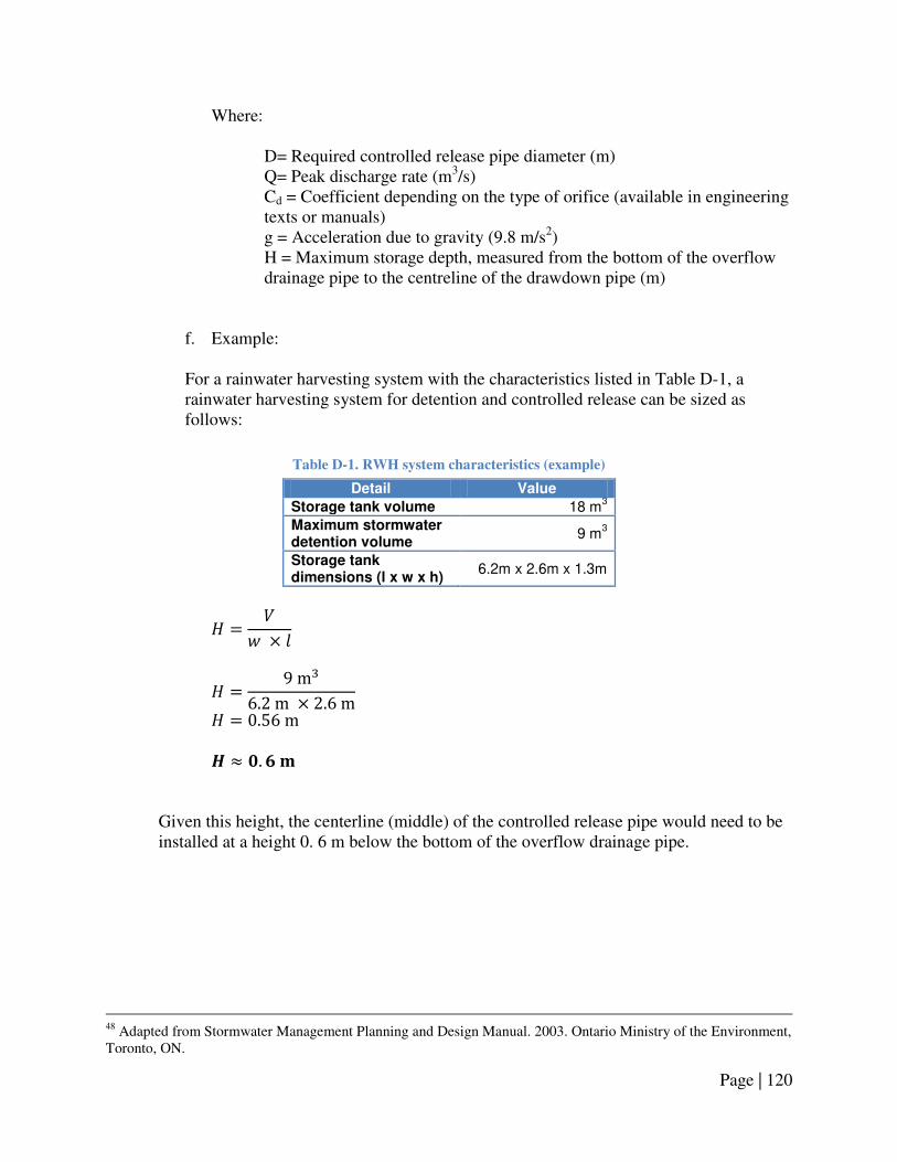
Page | 120
Where:
D= Required controlled release pipe diameter (m) Q= Peak discharge rate (m3/s) Cd = Coefficient depending on the type of orifice (available in engineering texts or manuals) g = Acceleration due to gravity (9.8 m/s2) H = Maximum storage depth, measured from the bottom of the overflow drainage pipe to the centreline of the drawdown pipe (m)
f. Example:
For a rainwater harvesting system with the characteristics listed in Table D-1, a rainwater harvesting system for detention and controlled release can be sized as follows:
Table D-1. RWH system characteristics (example)
Detail Value
Storage tank volume 18 m3
Maximum stormwater detention volume
9 m3
Storage tank dimensions (l x w x h)
6.2m x 2.6m x 1.3m
Given this height, the centerline (middle) of the controlled release pipe would need to be installed at a height 0. 6 m below the bottom of the overflow drainage pipe.
48 Adapted from Stormwater Management Planning and Design Manual. 2003. Ontario Ministry of the Environment, Toronto, ON.

Page | 121
The peak discharge from the rainwater storage tank, over a 24 hour period would be:
⁄ ⁄
Assuming the depth in the cistern is 0.56 m when the full 9 m3 is being stored, the required pipe size would be:
√
√ √
Thus, from these calculations, a 10 mm diameter pipe is required, however, in practice, such a small orifice would not be used as it would be prone to clogging, or to freezing during the winter. A minimum orifice size recommended for controlled release pipes is 75 mm49. Consult the local conservation authority and/or municipality regarding the minimum controlled release pipe diameter sizing.
49 Low Impact Development Stormwater Management Manual (Draft).2008. Toronto and Region Conservation Authority, Toronto, ON. 75 mm is the minimum orifice size required for controlled release pipes in stormwater retention ponds located in the City of Toronto.

Page | 122
Design & Sizing of Soakaway Pits
Soakaway pits are comprised of an excavated space filled with a non-porous material, surrounded by an outer filter fabric. A basic infiltration trench, be suitable for most RWH systems, is illustrated below in Figure D-2.
Figure D-2. Sketch of a typical soakaway pit (cross-section view)
50
The materials required for a soakaway pit include:
1. Storage media – crushed stone of a uniform size, used to provide a non-porous structure for the pit.
2. Outer fabric – non-woven filter fabric (polypropylene geotextile), used to protect the storage media from becoming clogged by the surrounding soils.
3. Distribution pipes – perforated drainage pipe used to distribute rainwater uniformly throughout the entire pit/trench.
4. Filter layer - fine sand placed on the outer fabric on the bottom of the trench to filter impurities prior to infiltration.
50 Adapted from Stormwater Management Planning and Design Manual. 2003. Ontario Ministry of the Environment, Toronto, ON.
GRADE
OVERFLOW
DRAINAGE PIPING
FROM
RAINWATER TANK
PERFORATED PIPE
SOIL COVER
DEPTH OF STORAGE
DEPENDENT UPON
SOIL POROSITY
AND RETENTION
TIME SAND FILTER LAYER
NON-POROUS FILLER LAYER
(CRUSHED STONE OR GRAVEL)
OUTER FILTER FABRIC
SOAKAWAY PIT
OVERFLOW
DRAINAGE PIPE

Page | 123
1. General design considerations51:
a. The soakaway pit should be located at least 4 m [13 ft.] away from a building foundation or other buried structure, and 1.5 m [5 ft.] from buried water or utility lines;
b. The length of the pit (parallel to the overflow drainage pipe) should be maximized compared to the width;
c. The maximum height of the pit/trench should be 1.5 m [5 ft.]; d. The soakaway pit should be buried sufficiently to protect it from freezing.
2. To size a soakaway pit or infiltration trench, the following guidelines are provided for estimation purposes only52 :
a. The depth of the soakaway pit can be calculated using Equation D-5 (further details below):
Equation D-5
Where: d = Maximum allowable depth of the soakaway pit (m) P = Percolation rate (mm/hour) T = Drawdown time (hour)
b. Given the storage depth, the size (area) of the soakaway pit can then be calculated
using Equation D-6:
Equation D-6
Where: A = Surface area of soakaway pit (m2)
V = Runoff volume to be infiltrated (m3) d = Maximum allowable depth of the soakaway pit (m)
n = Porosity of storage media (0.4 for clear stone)
c. When performing Equation D-5 and Equation D-6, the following sizing guidelines are recommended:
51 Adapted from Stormwater Management Planning and Design Manual. 2003. Ontario Ministry of the Environment, Toronto, ON, and Low Impact Development Stormwater Management Manual (Draft).2008. Toronto and Region Conservation Authority, Toronto, ON. 52 Adapted from Stormwater Management Planning and Design Manual. 2003. Ontario Ministry of the Environment, Toronto, ON.
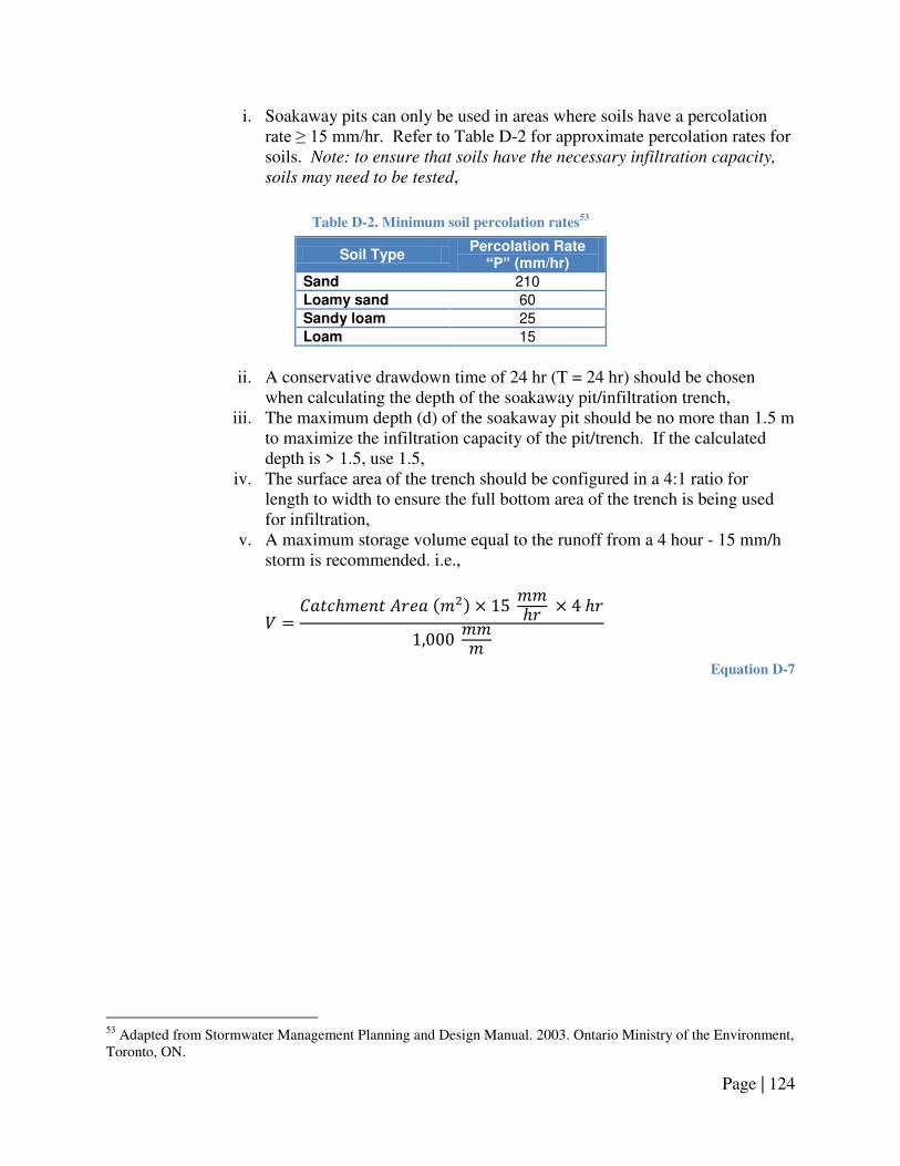
Page | 124
i. Soakaway pits can only be used in areas where soils have a percolation rate ≥ 15 mm/hr. Refer to Table D-2 for approximate percolation rates for soils. Note: to ensure that soils have the necessary infiltration capacity,
soils may need to be tested,
Table D-2. Minimum soil percolation rates53
Soil Type Percolation Rate “P” (mm/hr)
Sand 210
Loamy sand 60
Sandy loam 25
Loam 15
ii. A conservative drawdown time of 24 hr (T = 24 hr) should be chosen
when calculating the depth of the soakaway pit/infiltration trench, iii. The maximum depth (d) of the soakaway pit should be no more than 1.5 m
to maximize the infiltration capacity of the pit/trench. If the calculated depth is > 1.5, use 1.5,
iv. The surface area of the trench should be configured in a 4:1 ratio for length to width to ensure the full bottom area of the trench is being used for infiltration,
v. A maximum storage volume equal to the runoff from a 4 hour - 15 mm/h storm is recommended. i.e.,
Equation D-7
53 Adapted from Stormwater Management Planning and Design Manual. 2003. Ontario Ministry of the Environment, Toronto, ON.
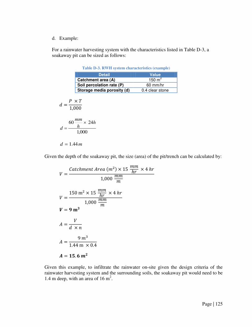
Page | 125
d. Example:
For a rainwater harvesting system with the characteristics listed in Table D-3, a soakaway pit can be sized as follows:
Table D-3. RWH system characteristics (example)
Detail Value
Catchment area (A) 150 m2
Soil percolation rate (P) 60 mm/hr
Storage media porosity (d) 0.4 clear stone
000,1
2460 hh
mm
d
md 44.1
Given the depth of the soakaway pit, the size (area) of the pit/trench can be calculated by:
Given this example, to infiltrate the rainwater on-site given the design criteria of the rainwater harvesting system and the surrounding soils, the soakaway pit would need to be 1.4 m deep, with an area of 16 m2.

Page | 126
3. The soakaway pit must be buried at a sufficient depth to protect it from frost. Figure D-3 indicates the required soil cover, based on soil type and depth of soakaway pit.
Figure D-3. Soil cover for soakaway pits, based on frost heave
54
Assessment of Site Soil Infiltration Loading Rate (Percolation Rate)
1. To assist in determining the feasibility and design aspects of utilizing a soakaway pit as
an overflow discharge location, soil conditions, including the soil percolation rate, must be determined:
a. Refer to the Alberta Private Sewage Systems Standard of Practice 2009 for complete guidelines and prescriptive requirements for the performance of a site evaluation and soil profile. The following guidelines are provided for guidance purposes only55:
b. A sufficient number of suitably located soil profiles in the area of the soakaway pit shall be examined and described to adequately determine the variability of the soils on the proposed soakaway pit site:
i. A minimum of two test pit excavations shall be investigated at the proposed location for the soakaway pit site, using excavated soil pits and intact cores of soil to assess the infiltration capacity of the soil,
ii. The soil profiles shall be investigated to a minimum depth of 1.8 m [6 ft.] below grade,
iii. Completing an investigation to a depth that achieves the objectives of the site evaluation and in no case shall the depth be less than 300 mm [12 in.] deeper than the vertical separation distance required below the proposed soakaway pit site.
54 Stormwater Management Planning and Design Manual. 2003. Ontario Ministry of the Environment, Toronto, ON. 55 Adapted from Alberta Private Sewage Systems Standard of Practice 2009. Alberta Municipal Affairs, Edmonton, AB.

Page | 127
c. The characteristics of each soil profile investigated shall be described using Canadian System of Soil Classification nomenclature and include the following in the soil profile description56:
i. Horizons: the distance from ground surface to the top and bottom of each horizon observed shall be measured and the distinctness and topography of the horizon boundaries described,
ii. Colour: for each horizon identified, the matrix color and the quantity, size, contrast, and color of any redoximorphic features present shall be described,
iii. Texture: 1. For each horizon identified, the texture class including any
appropriate texture modifier shall be reflected in the evaluation report, and
2. A soil sample of the most restricting layer affecting the design shall be collected and analyzed at a laboratory using a recognized grain or particle size analysis method to determine the texture classification of the sample,
3. Note: Where a sand fraction modifier such as coarse, medium,
fine, or very fine sand is part of the soil texture classification
description the laboratory analysis must include the determination
of the sand fraction size distribution. iv. Structure: for each horizon identified, the grade of soil structure observed
and the size and type of grades, 0-3 shall be described, v. Consistence: for each structure observed in the profile the consistence of
the soil peds shall be described, vi. Compaction: any zones of compaction in the soil profile shall be described
to estimate its affect on water movement, root penetration and aeration, vii. Saturated zones: for each soil profile described, the depth to any water or
the depth to the estimated seasonally high zone of saturated soil based on redoximorphic or other appropriate features shall be measured,
viii. Bedrock and near impermeable soil layers: depth to bedrock and near impermeable soil layers observed shall be measured from the ground surface, and
ix. Flow restricting horizons: for each soil profile described, any horizon that is expected to significantly restrict downward water flow shall be identified and measured to determine its depth below ground surface (Note: such horizons may be discerned by evidence of episaturation above the horizon).
d. The infiltration loading rates (percolation rates) suitable for the soil profile identified at the site, as characterized by the texture and structure of the soil shall be determined using Table D-4 and Figure D-4.
56 For further details refer to the Field Book for Describing and Sampling Soils or the Soil Survey Manual available on the web at: http://sis.agr.gc.ca/cansis/intro.html or as included in the Alberta Private Sewage Soils Description Manual.

Page | 128
e. The percolation rate utilized when sizing the soakaway pit shall not exceed the amount set out in Table D-4 based on the soil characteristics identified by the site evaluation.

Page | 129
Table D-4. Infiltration loading rates for rainwater57
Soil characteristics Infiltration
loading rate,
L/day/m2
[gal/day/ft²]
Texture
Structure
Shape Grade
COS, S, LCOS,
LS -- 0SG 65.1 [1.6]
FS,VFS,LFS,LVFS -- 0SG 40.7 [ 1.0]
CSL, SL
-- 0M 24.4 [0.6]
PL 1 20.3 [0.5]
2,3 12.2 [0.3]
PR/BK
/GR
1 30.9 [0.76]
2,3 40.7 [1.0]
FSL,VFSL
-- 0M 20.3 [0.5]
PL 1,2,3 0.0 [0.0]
PR/BK
/GR
1 24.4 [0.6]
2,3 32.6 [0.8]
L
-- 0M 20.3 [0.5]
PL 1,2,3 -
PR/BK
/GR
1 24.4 [0.6]
2,3 32.6 [0.8]
SIL
-- 0M 8.1 [0.2]
PL 1,2,3 0.0 [0.0]
PR/BK
/GR
1 24.4 [0.6]
2,3 32.6 [0.8]
SCL, CL, SICL
-- 0M 0.0 [0.0]
PL 1,2,3 0.0 [0.0]
PR/BK
/GR
1 12.2 [0.3]
2,3 24.4 [0.6]
SC, C , SIC
-- 0M 0.0 [0.0]
PL 1,2,3 0.0 [0.0]
PR/BK
/CR
1 0.0 [0.0]
2,3 16.3 [0.4]
COS – Coarse Sand LVFS – Loamy Very Fine Sand SI – Silt
MS –Medium Sand COSL – Coarse Sandy Loam SCL – Sandy Clay Loam
LCOS – Loamy Coarse Sand MSL – Medium Sandy Loam CL – Clay Loam
LMS – Loamy Medium Sand FSL – Fine Sandy Loam SICL – Silty Clay Loam
FS – Fine Sand VFSL – Very Fine Sandy Loam SC – Sandy Clay
LFS – Loamy Fine Sand L – Loam SIC – Silty Clay
VFS – Very Fine Sand SIL – Silt Loam C – Clay HC – Heavy Clay
PL – Platy PR – Prismatic BK – Blocky GR – Granular M – Massive SG—Single Grain
0 – Structureless 1 – Weak 2 – Moderate 3 – Strong
57 Alberta Municipal Affairs. 2010. Edmonton, AB.

Page | 130
Figure D-4. Soil texture classification triangle
58
58 Alberta Private Sewage Systems Standard of Practice 2009. Alberta Municipal Affairs, Edmonton, AB.