alabama supplements to the - efotg … supplements to the national engineering field handbook...
TRANSCRIPT

AL-i(i) (210-VI-NEH, Amend. AL4, September 2006)
ALABAMA SUPPLEMENTS TO THE
NATIONAL ENGINEERING FIELD HANDBOOK
CHAPTER 8. TERRACES
Contents
PAGE Terrace Spacing ................................................................................................................... AL8-21(1) Spacing Affected by Cross Section ................................................................................... AL8-24(1) Layout ...................................................................................................................................... AL8-33(1) Truck method of Parallel Terrace Layout .................................................................... AL8-33(1) Design ................................................................................................................................... AL8-55(1) Graded Terraces with Underground Outlets .............................................................. AL8-55(1) Detention Time .......................................................................................................... AL8-55(1) Terrace Storage Capacity ......................................................................................... AL8-55(1) Risers, Size, and Locations ...................................................................................... AL8-55(1) Detachable Plastic or Rigid Metal Risers for Underground Outlets .......................... AL8-55(2) Outlet Section of Pipe ............................................................................................... AL8-55(2) Materials .................................................................................................................... AL8-55(4) Runoff Storage .......................................................................................................... AL8-55(4) Sediment Storage ..................................................................................................... AL8-55(6) Design Procedure-All Terraces With Underground Outlets ...................................... AL8-55(6) Design Procedure-Unstable Bypass ......................................................................... AL8-55(6) Design Procedure-Stable Bypass ............................................................................. AL8-55(7) Design of the Underground Outlet Conduit ............................................................... AL8-55(7) Underground Outlet Installation ................................................................................ AL8-55(8) Intake or Riser ........................................................................................................... AL8-55(8) Design Example-Storage Terrace with Underground Outlet ........................................... AL8-55(15) Records and Maintenance ................................................................................................... AL8-55(18)
FIGURES
Figure AL8-1 Cross section of effective cultivated length of slope. ............................. AL8-24(1) Figure AL8-2 Concrete culvert stilling well for underground outlet. ............................. AL8-55(3) Figure AL8-3 A method of backfilling the underground conduit trench. ...................... AL8-55(8) Figure AL8-4 Terrace system with underground outlets survey notes and design. ... AL8-55(19) Figure AL8-5 Terrace system survey notes and design. ................................................ AL8-55(25)

AL-i(ii) (210-VI-NEH, Amend. AL4, September 2006)
TABLES
Table AL8-1. Terrace spacing for different farming equipment widths. ........................ AL8-24(1) Table AL8-2. Runoff for 10-year, 24-hour rainfall. ........................................................... AL8-55(5) Table AL8-3. Sediment storage for terraces and sediment basins. ............................... AL8-55(6) Table AL8-4. Per cent storage factor. ............................................................................... AL8-55(7) Table AL8-5a. Natural storage above terrace for 14-foot front slopes. ......................... AL8-55(9) Table AL8-5b. Natural storage above terrace for 28-foot front slopes. ......................... AL8-55(10) Table AL8-5c. Natural storage above terrace for 3 to 1 front slopes. ............................ AL8-55(11) Table AL8-5d. Natural storage above terrace for 2½ to 1 front slopes. ........................ AL8-55(13)
AL8-21(1) (210-VI-NEH, Amend. AL4, September 2006)
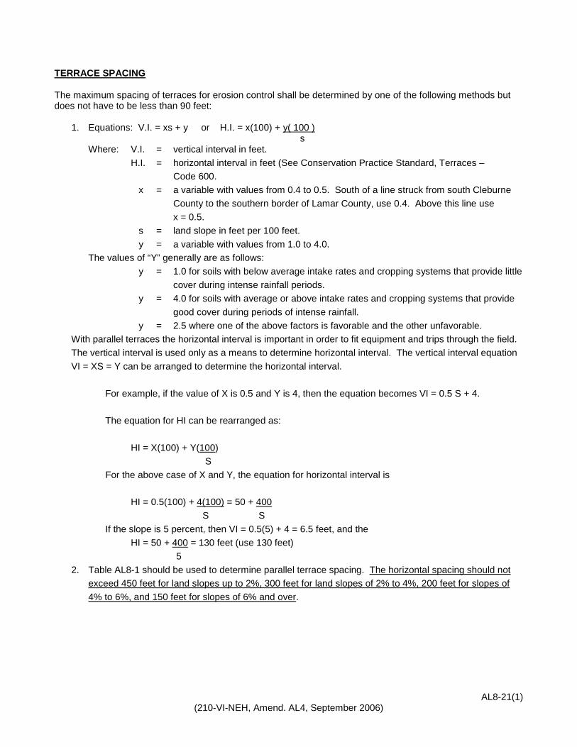
TERRACE SPACING
The maximum spacing of terraces for erosion control shall be determined by one of the following methods but does not have to be less than 90 feet:
1. Equations: V.I. = xs + y or H.I. = x(100) + y( 100 ) s Where: V.I. = vertical interval in feet. H.I. = horizontal interval in feet (See Conservation Practice Standard, Terraces –
Code 600. x = a variable with values from 0.4 to 0.5. South of a line struck from south Cleburne
County to the southern border of Lamar County, use 0.4. Above this line use x = 0.5.
s = land slope in feet per 100 feet. y = a variable with values from 1.0 to 4.0. The values of “Y” generally are as follows: y = 1.0 for soils with below average intake rates and cropping systems that provide little
cover during intense rainfall periods. y = 4.0 for soils with average or above intake rates and cropping systems that provide
good cover during periods of intense rainfall. y = 2.5 where one of the above factors is favorable and the other unfavorable. With parallel terraces the horizontal interval is important in order to fit equipment and trips through the field. The vertical interval is used only as a means to determine horizontal interval. The vertical interval equation VI = XS = Y can be arranged to determine the horizontal interval. For example, if the value of X is 0.5 and Y is 4, then the equation becomes VI = 0.5 S + 4. The equation for HI can be rearranged as: HI = X(100) + Y(100) S For the above case of X and Y, the equation for horizontal interval is HI = 0.5(100) + 4(100) = 50 + 400 S S If the slope is 5 percent, then VI = 0.5(5) + 4 = 6.5 feet, and the HI = 50 + 400 = 130 feet (use 130 feet) 5 2. Table AL8-1 should be used to determine parallel terrace spacing. The horizontal spacing should not
exceed 450 feet for land slopes up to 2%, 300 feet for land slopes of 2% to 4%, 200 feet for slopes of 4% to 6%, and 150 feet for slopes of 6% and over.

AL8-24(1) (210-VI-NEH, Amend. AL4, September 2006)
SPACING AFFECTED BY CROSS SECTION The effective cultivated length of slope (Figure AL8-1) between terraces varies with the type of cross section. Spacing can be increased 10 percent for alignment or location to adjust for farm machinery and an additional 10% with underground outlets. Figure AL8-1. Cross section of effective cultivated length of slope.
Width of One Trip Across Field
No. of Rows
Width of Row (inches)
30 32 34 36 38 40
4 10’ - 0” 10’ - 8” 11’ - 4” 12’ - 0” 12’ - 8” 13’ - 4”
6 15’ - 0” 16’ - 0” 17’ - 0” 18’ - 0” 19’ - 0” 20’ - 0”
8 20’ - 0” 21’ - 4” 22’ - 8” 24’ - 0” 25’ - 4” 26’ - 8”
12 30’ - 0” 32’ - 0” 34’ - 0” 36’ - 0” 38’ - 0” 40’ - 0”
16 40’ - 0” 42’ - 8” 45’ - 4” 48’ - 0” 50’ - 8” 53’ - 4”
FARMING WIDTHS “f” FOR DIFFERENT MACHINERY SIZES (rows)
No. of Trips
4 Rows 6 Rows 8 Rows
30” 36” 38” 40” 30” 36” 38” 40” 30” 36” 38” 40” 4 72’-0” 76’-0” 80’-0” 80’-0” 96”-0” 101’-4” 106’-8” 5 66’-8” 75’-0” 90’-0” 95’-0” 100’-0” 100’-0” 120’-0 126’-8” 133’-4” 6 76’-0” 80’-0” 90’-0” 108’-0” 114’-0” 120’-0” 120’-0” 114’-0” 152’-0” 160’-0” 7 84’-0” 88’-8” 93’-4” 105’-0” 126’-0” 133’-0” 140’-0” 140’-0” 168’-0” 177’-4” 186’-8” 8 80’-0” 96’-0” 101’-4” 106’-8” 120’-0” 144’-0” 152’-0” 160’-0” 160’-0” 192’-0” 202’-8” 213’-4” 9 90’-0” 108’-0” 114’-0” 120’-0” 135’-0” 162’-0” 171’-0” 180’-0” 180’-0” 216’-0” 228’-0” 240’-0”
10 100’-0” 120’-0” 126’-8” 133’-4” 150’-0” 180’-0” 190’-0” 200’-0” 200’-0” 240’-0” 253’-4” 266’-8” 11 110’-0” 132’-0” 139’-4” 146’-8” 165’-0” 198’-0” 209’-0” 220’-0” 220’-0” 264’-0” 278’-8” 293’-4” 12 120’-0” 144’-0” 152’-0” 160’-0” 180’-0” 216’-0” 228’-0” 240’-0” 240’-0” 288’-0” 304’-0” 320’-0” 13 130’-0” 156’-0” 164’-8” 173’-4” 195’-0” 234’-0” 247’-0” 260’-0” 260’-0” 312’-0” 324’-4” 346’-8” 14 140’-0” 168’-0” 177’-4” 186’-8” 210’-0” 252’-0” 266’-0” 280’-0” 280’-0” 336’-0” 354’-8” 373’-4” 15 150’-0” 180’-0” 190’-0” 200’-0” 225’-0” 270’-0” 285’-0” 300’-0” 300’-0” 360’-0” 380’-0” 400’-0” 16 160’-0” 192’-0” 202’-8” 213’-4” 240’-0” 288’-0” 304’-0” 320’-0” 320’-0” 384’-0” 405’-4” 426’-8” 17 170’-0” 204’-0” 215’-4” 226’-8” 255’-0” 306’-0” 323’-0” 340’-0” 340’-0” 408’-0” 430’-8” 18 180’-0” 216’-0” 228’-0” 240’-0” 270’-0” 324’-0” 342’-0” 360’-0” 360’-0” 432’-0” 19 190’-0” 228’-0” 240’-8” 253’-4” 285’-0” 342’-0” 361’-0” 380’-0” 380’-0” 20 200’-0” 240’-0” 253’-4” 266’-8” 300’-0” 360’-0“ 380’-0“ 400’-0” 400’-0”
Table AL8-1. Terrace spacing for different farming equipment widths.
AL8-33(1) (210-VI-NEH, Amend. AL4, September 2006)
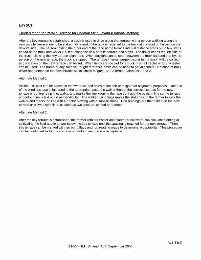
LAYOUT Truck Method for Parallel Terrace for Contour Strip Layout (Optional Method) After the key terrace is established, a truck is used to drive along that terrace with a person walking along the new parallel terrace line to be staked. One end of the tape is fastened to the truck at the front of the bed on the driver’s side. The person holding the other end of the tape at the terrace interval distance starts out a few steps ahead of the truck and walks 100 feet along the new parallel terrace and stops. The driver keeps the left side of the truck following the key terrace alignment. When daylight can be seen between the truck cab and bed by the person on the new terrace, the truck is stopped. The terrace interval, perpendicular to the truck, will be correct and a station on the new terrace can be set. When fields are too wet for a truck, a small tractor or four wheeler can be used. The frame or any suitable upright reference posts can be used to get alignment. Rotation of truck driver and person on the new terrace will minimize fatigue. See Alternate Methods 1 and 2. Alternate Method 1: Visible 3 ft. post can be placed in the two truck bed holes at the cab or tailgate for alignment purposes. One end of the windless tape is fastened to the appropriate post, the walker then at the correct distance for the new terrace or contour strip line, walks, and marks the line keeping the tape tight and the posts in line so the terrace or contour line is laid out in perpendicular. The walker using flags marks the stations and the farmer follows the walker and marks the line with a tractor plowing with a subsoil shank. Rod readings are then taken on the new terrace or plowed strip lines as soon as two lines are staked or marked. Alternate Method 2: After the key terrace is established, the farmer with his tractor and planter or cultivator can simulate planting or cultivating the field above and/or below the key terrace until the spacing is reached for the next terrace. Then this terrace can be marked with terracing flags and rod reading made to determine acceptability. This procedure can be continued as long as terrace or contour line grade is acceptable.


AL8-55(1) (210-VI-NEH, Amend. AL4, September 2006)
DESIGN
Graded Terraces with Underground Outlets An emergency bypass should be provided when possible at the edge of the field or away from the riser to reduce possibility of terrace over-topping and failure. Detention Time A detention time of 24 hours is recommended for most fields. Terrace Storage Capacity Many terraces have both natural and excavated storage. However, if sediment storage is not added to the total design storage requirements, only natural storage should be computed to determine the ridge height. The additional storage excavated during construction will compensate for the lack of sediment storage in most situations. Risers, Size, and Locations The riser shall be located at the lowest spot on the terrace profile, or the terrace must be graded to the riser in order to drain all the terrace channel. The riser shall be placed uphill from the terrace ridge a distance equal to a multiple of the equipment width (min. 8-row) so that all equipment used will pass. Spacing of the risers shall be as recommended for terrace spacing in Table 8-1 and emphasis will be on spacing for multiple of round trips. The riser should be 6 in. in diameter or larger with openings in the 5 ft. riser above ground and holes for subsurface drainage in the first four beet below ground. These holes shall be rectangular or drilled uniformly smooth and round for hydraulic efficiency using a round hole saw. The openings shall be sufficiently numerous to pass the required flow even if some are obstructed. A minimum of 12 1-in. diameter holes per linear foot or equivalent is recommended. Flexible risers should be guarded by a post (or two) in line with the rows and be marked for visibility. Risers should be attached to the post using a figure-eight wrap of galvanized wire or strap that in turn is secured to the post. The riser should be surrounded by a gravel drain fill to improve drainage. The gravel drain material needs to surround the riser in a 24-in. diameter or square column from the riser bottom to the ground surface. In “B”, “C”, and “D” soils, drain material is essential. Artificial filter material such as spun fiberglass, bonded nylon fabric, and plastic filter cloth will suffice in “A” soils. An orifice plate will usually be installed to meter the desired discharge into a common conduit outlet when there are two or more terraces involved. However, since actual field conditions will impact the hydraulics of these structures, systems may be designed without orifice plates by experienced personnel with guidance from the resource engineer. Subsurface drainage pipe should be used through wet soils for the outlet conduit, with flow in the intake risers restricted with an orifice so as to prevent pressure flow in the conduit. If sealed or continuous pipe or tubing is used for the conduit, flow shall be controlled in the risers in the upper terraces to prevent reverse flow in the risers of the lower terraces. Flow will be controlled by the use of an orifice located near the bottom of the intake riser by sizing the outlet conduit or by sizing the intake lateral. The diameter of the orifices can be determined from the following formula as shown in the design example:

AL8-55(2) (210-VI-NEH, Amend. AL4, September 2006)
Orifice Size Formula A = Q/[C x (2gH) 0.5] Where: A = area of orifice in ft2 Q = discharge rate of orifice in cfs C = coefficient = 0.60 g = 32.2 ft./sec2 H = (0.5 X d1) + d2 d1 = water depth in feet d2 = depth of orifice below ground level in feet Note: 1 cfs = 23.802 ac.in./24 hr. Detachable Plastic or Rigid Metal Risers for Underground Outlets Risers for the terrace underground outlets are damaged by cattle, farm equipment and fire. Installation of detachable PVC sewer pipe risers or metal risers will limit the damage from most sources. For moving and maintenance activities the upper riser portion can be removed and then replaced. The following and installation details are required:
1. Thin wall PVC sewer pipe meeting ASTM D-2729 or SDR-26 PVC pipe are acceptable materials.
2. Above-ground risers will have a minimum 12-1 in. holes/foot for length of pipe.
3. Below ground riser will have 12- ¼ in. holes/foot and be surrounded by 2 ft. of concrete gravel.
4. PVC coupling is glued to below ground section only. Above ground section is inserted about 1 inch for ease of removal.
5. Joint filler or tape maybe needed between pipe and orifice plate.
Outlet Section of Pipe The outlet shall be protected against erosion, undermining of the conduit, damage by equipment, damage during periods of submergence, and entry of rodents or other animals. A continuous 10-ft. section of non-perforated rigid pipe (plastic not recommended) with an animal guard or flap gate will be used at the outlet end of the line. The outlet should be at least 1 ft. above the normal elevation or low flow in the waterway or ditch. When satisfactory pipe cover or outlet is not available, the stilling well should be used. (See Figure AL8-2.) The diameter of the stilling well will normally be a minimum 3X barrel diameter. If the outlet is stable for concentrated flow and a stilling well is only being installed to maintain pipe cover, the stilling well will be a minimum 2x barrel diameter. The cutout in the well will normally be 1/3 diameter and 15 in. high but may be designed using the weir flow formula: Q = 3.1 x L x H1.5 where L is the length of the weir and H is the head.

AL8-55(3) (210-VI-NEH, Amend. AL4, September 2006)
Figure AL8-2. Concrete Culvert Stilling Well for Underground Outlet.

AL8-55(4) (210-VI-NEH, Amend. AL4, September 2006)
The pipe and its installation shall conform to the following requirements:
1. Where there is a hazard of vegetation burning at the outlet, the outlet pipe shall be fabricated from fire resistant material. Where the hazard of burning is high, the riser outlet also shall be fire resistant.
2. Two-thirds or more of the 10-ft. outlet section shall be buried in the ditch bank and the cantilevered section shall extend to the toe of the ditch side slope or the side slope shall be protected from erosion.
3. Where floating debris may damage the outlet pipe, the outlet shall be recessed to the extent that the cantilevered portion of the pipe will be protected from the current in the ditch.
4. Headwalls which are used at subsurface drain outlets shall be adequate in strength and design to avoid washouts and other failures. To protect against trench erosion, use a mound of soil over the pipe.
Watertight conduit strong enough to withstand the loads upon it shall be used where outlets cross under roadways or ditches.
Materials Pipe for the riser will be limited to corrugated or smooth plastic, steel, or aluminum. Durable smooth plastic pipe may be used provided it will withstand severe weather and temperature conditions and wear and tear from farm equipment and livestock. If corrugated plastic tubing is used for the riser, it shall be supported and protected from damage by livestock and farm equipment. When livestock is a problem, the answer may be three post set in a triangular pattern and wrapped with barbed wire. Pipe for outlet conduit section shall be clay or concrete sewer pipe, smooth steel pipe, corrugated metal pipe, asbestos cement pipe, or plastic pipe that will withstand loads applied by earth cover and heavy farm equipment. Materials shall meet strength and durability requirements of the site. Pipe materials shall conform to the specifications set forth in Conservation Practice Standard, Subsurface Drain – Code 606. Orifice plates shall be made of metal or durable plastic that will withstand the pressure and flow of water through the riser. Runoff Storage Sufficient storage will be provided to protect the terrace from overtopping. The amount of storage is generally based on a 10-year frequency 24-hour storm. Calculate the runoff or use values found in Table AL8-2.

AL8-55(5) (210-VI-NEH, Amend. AL4, September 2006)
Runoff for 10-yr., 24-hr. rainfall Curve Nos. 64,75,82 and 85 for soil hydr. groups
Table AL8-2. Runoff for 10-year, 24-hour rainfall.
County Hydrologic Soil Group County Hydrologic Soil Group A B C D A B C D
AUTAUGA 2.70 3.80 4.54 4.87 HOUSTON 3.23 4.41 5.20 5.54
BALDWIN 4.76 6.14 7.01 7.38 JACKSON 1.85 2.78 3.44 3.74
BARBOUR 2.85 3.97 4.73 5.06 JEFFERSON 2.33 3.37 4.08 4.40
BIBB 2.55 3.63 4.36 4.68 LAMAR 2.19 3.20 3.90 4.21
BLOUNT 2.12 3.11 3.80 4.11 LAUDERDALE 1.91 2.86 3.53 3.83
BULLOCK 2.78 3.89 4.64 4.97 LAWRENCE 1.98 2.94 3.62 3.93
BUTLER 3.15 4.33 5.10 5.44 LEE 2.48 3.54 4.26 4.59
CALHOUN 2.12 3.11 3.80 4.11 LIMESTONE 1.91 2.86 3.53 3.83
CHAMBERS 2.41 3.45 4.17 4.49 LOWNDES 2.85 3.97 4.73 5.06
CHEROKEE 2.05 3.03 3.71 4.02 MACON 2.63 3.71 4.45 4.78
CHILTON 2.55 3.63 4.36 4.68 MADISON 1.91 2.86 3.53 3.83
CHOCTAW 3.00 4.15 4.92 5.25 MARENGO 2.85 3.97 4.73 5.06
CLARKE 3.31 4.50 5.29 5.64 MARION 2.12 3.11 3.80 4.11
CLAY 2.33 3.37 4.08 4.40 MARSHALL 1.98 2.94 3.62 3.93
CLEBURNE 2.12 3.11 3.80 4.11 MOBILE 4.59 5.95 6.81 7.18
COFFEE 3.31 4.50 5.29 5.64 MONROE 3.46 4.68 5.48 5.83
COLBERT 1.98 2.94 3.62 3.93 MONTGOMERY 2.78 3.89 4.64 4.97
CONECUH 3.54 4.77 5.58 5.92 MORGAN 1.98 2.94 3.62 3.93
COOSA 2.55 3.63 4.36 4.68 PERRY 2.70 3.80 4.54 4.87
COVINGTON 3.62 4.86 5.67 6.02 PICKENS 2.48 3.54 4.26 4.59
CRENSHAW 3.08 4.24 5.01 5.35 PIKE 2.93 4.06 4.82 5.16
CULLMAN 2.12 3.11 3.80 4.11 RANDOLPH 2.26 3.28 3.99 4.30
DALE 3.08 4.24 5.01 5.35 RUSSELL 2.63 3.71 4.45 4.78
DALLAS 2.85 3.97 4.73 5.06 SHELBY 2.41 3.45 4.17 4.49
DEKALB 1.91 2.86 3.53 3.83 ST. CLAIR 2.19 3.20 3.90 4.21
ELMORE 2.63 3.71 4.45 4.78 SUMTER 2.78 3.89 4.64 4.97
ESCAMBIA 4.02 5.31 6.15 6.50 TALLADEGA 2.33 3.37 4.08 4.40
ETOWAH 2.05 3.03 3.71 4.02 TALLAPOOSA 2.48 3.54 4.26 4.59
FAYETTE 2.26 3.28 3.99 4.30 TUSCALOOSA 2.48 3.54 4.26 4.59
FRANKLIN 2.05 3.03 3.71 4.02 WALKER 2.19 3.20 3.90 4.21
GENEVA 3.46 4.68 5.48 5.83 WASHINGTON 3.54 4.77 5.58 5.92
GREENE 2.63 3.71 4.45 4.78 WILCOX 3.00 4.15 4.92 5.25
HALE 2.63 3.71 4.45 4.78 WINSTON 2.12 3.11 3.80 4.11
HENRY 2.93 4.06 4.82 5.16

AL8-55(6) (210-VI-NEH, Amend. AL4, September 2006)
Sediment Storage
Sediment storage needs may be estimated using the following table AL8-3 after the average annual soil loss in tons per acre has been determined for the terrace interval. Where large areas of the terrace interval will be disturbed during construction, additional sediment storage may be added to allow for the high first year accumulation. However, if construction is performed from the front and natural storage design tables are used, additional sediment storage is not required.
Table AL8-3. Sediment Storage for Terraces and Basins.
Soil Loss Tons per acre
per year
Estimated 10-year Sediment Yield Inches per
Unit of Drainage Area (in.)
1 .07 2 .14 3 .21 4 .28 5 .34 7 .48 10 .69 12 .83 15 1.03 18 1.24
Design Procedure – All Terraces With Underground Outlets
1. Determine the design area of the terrace and the required inches of storage. (See Table AL8-2.) If the available storage will be calculated using excavated plus natural storage, sediment storage must be added to the required storage. Multiply these figures to obtain the maximum volume of storage required in acre-inches.
2. Analyze the rod readings and determine the maximum bypass elevation that would be practical to construct. If the maximum elevation will not result in a channel (stable) bypass, the unstable bypass design procedure will be used.
Design Procedure – Unstable Bypass If the terrace being designed will bypass over the top or onto an unstable area, the terrace should contain a 10-year, 24-hour storm. The terrace may be designed to store 100% of the storm with the pipe designed only to dewater this storage within the specified detention time (usually 24 hours) or the storage requirement may be reduced by increasing the pipe size. However, the minimum storage for a terrace with an unstable bypass shall be 33%. For terraces with less than 100% storage, the pipe shall be designed to carry the volume of storage required multiplied by a factor from Table AL8-4.
A. If the unstable bypass design must be used, compute the natural storage in cu.ft./ft. from Table AL8-5a, b, c, or d, multiply by the distance between rod readings and divide by 3,630 to obtain the available storage in acre-inches.
B. Compute the % stored by dividing the available storage by the volume of storage required
C. Compute the % stored by dividing the available storage by the volume of storage required. If less than 33%, the bypass will have to be raised.
D. Size the outlet pipe by multiplying the maximum required storage by the appropriate multiplier factor from Table AL8-4 to obtain the volume to be dewatered in 24 hours.

AL8-55(7) (210-VI-NEH, Amend. AL4, September 2006)
Table AL8-4. Percent storage factor.
% Storage Multiplier Factor
33 3.0 35 2.9 40 2.5 45 2.2 50 2.0 55 1.8 60 1.7 65 1.5 70 1.4 75 1.3 80 1.3 85 1.2 90 1.1 95 1.1 100 1.0
Design Procedure – Stable Bypass If the terrace being designed will bypass along the channel onto a stable area, the constructed terrace ridge height will be increased by 0.5 ft. plus 10% settlement. The pipe may be designed only to dewater the available storage within the specified detention time (usually 24 hours). However, it is highly recommended that all pipes be sized to remove the maximum required storage in 24 hours. A. The capacity will be based on the available storage. Compute the natural storage in cu.ft./ft. from Table
AL8-5a, b, c, or d, multiply by the distance between rod readings and divide by 3,630 to obtain the available storage in acre-inches.
B. Size the outlet pipe.
Design of the Underground Outlet Conduit The underground outlet conduit is designed to remove the calculated volume of terrace storage in a specified time interval. The outlet conduit can be designed by either a computer program or the formula below. The underground outlet should be designed for open channel flow. The design procedure is to start with the top terrace and accumulate the volume or discharge rate of each terrace, moving downhill. The pipe sizes can be determined from the following formula as shown in the design example: Pipe Size Formula D = (K x Q 0.375) /S 0.1875 Where: D = pipe diameter in inches K = 3.4007 for corrugated tubing K = 2.9208 for smooth Q = design outflow in cfs S = slope of pipe in ft./ft. Note: 1 cfs = 23.802 ac.in./24 hr.

AL8-55(8) (210-VI-NEH, Amend. AL4, September 2006)
Underground Outlet Installation Underground outlets used to dispose of impounded water from terraces are, in fact, mechanical spillways through earthen embankments. In order for these spillways to function properly and not be washed out, proper material selection, adequate moisture and good construction techniques are required. Figure AL8-3 shows details of underground conduit installation and backfill.
Figure AL8-3. A method of backfilling the underground conduit trench. Intake or Riser The riser extends above the ground and directs the flow into the underground outlet. Intakes or risers may be placed on a lateral leading to the main line. The main conduit and lateral may be of perforated conduit. The intake should be of sturdy construction and securely connected to the lateral conduit. The riser should extent to the top elevation of the terrace ridge or minimum of 3 feet. This gives a factor of safety against plugging by trash and permits operators of equipment to see them. It also permits sediment to build up gradually over the years without having to raise the riser.

AL8-55(9) (210-VI-NEH, Amend. AL4, September 2006)
Table AL8-5a. Natural Storage Above Terrace for 14-ft. Front Slopes (cu.ft./lin.ft.).
d Land Slope, SL 1% 2% 3% 4% 5% 6% 8% 10% 12% 14%
0.1 1 1 1 1 1 1 1 1 1 1 0.2 3 2 2 2 2 2 2 2 2 2 0.3 7 4 4 3 3 3 3 3 3 2 0.4 11 7 6 5 4 4 4 4 4 3 0.5 16 10 8 7 6 6 5 5 5 4 0.6 22 13 10 9 8 7 6 6 6 6 0.7 29 17 13 11 10 9 8 7 7 7 0.8 38 22 16 14 12 11 10 9 8 8 0.9 47 27 20 16 14 13 11 10 10 9 1.0 57 32 24 20 17 15 13 12 11 11 1.1 68 38 28 23 20 18 15 14 13 12 1.2 80 44 32 26 23 20 17 16 14 14 1.3 94 51 37 30 26 23 20 18 16 15 1.4 108 59 43 34 29 26 22 20 18 17 1.5 123 67 48 39 33 29 25 22 20 19 1.6 139 75 54 43 37 33 27 24 22 20 1.7 156 84 60 48 41 36 30 26 24 22 1.8 175 94 67 53 45 40 33 29 26 24 1.9 194 104 74 58 49 43 36 31 28 26 2.0 214 114 81 64 54 47 39 34 31 28 2.1 235 125 88 70 59 51 42 37 33 30 2.2 257 136 96 76 64 56 46 40 36 32 2.3 281 148 104 82 69 60 49 43 38 35 2.4 305 161 113 89 74 65 53 46 41 37 2.5 330 174 122 96 80 70 57 49 44 40 2.6 356 187 131 103 86 75 60 52 46 42 2.7 383 201 140 110 92 80 65 55 49 45 2.8 412 216 150 117 98 85 69 59 52 48 2.9 441 231 161 125 104 90 73 62 55 50 3.0 471 246 171 134 111 96 77 66 58 53 3.1 502 262 182 142 118 102 82 70 62 56 3.2 534 278 193 150 125 108 86 74 65 59 3.3 568 295 205 159 132 114 91 78 68 62 3.4 602 313 216 168 139 120 96 82 72 65 3.5 637 331 229 178 147 127 101 86 76 68 3.6 673 349 241 187 155 133 106 90 79 71 3.7 710 368 254 197 163 140 111 94 83 75 3.8 749 388 267 207 171 147 117 99 87 78 3.9 788 408 281 217 179 154 122 103 91 82 4.0 828 428 295 228 188 161 128 108 95 85 4.1 869 449 309 239 197 169 134 113 99 89 4.2 911 470 323 250 206 176 140 118 103 92 4.3 955 492 338 261 215 184 146 123 107 96 4.4 999 515 353 273 224 192 152 128 111 100 4.5 1044 538 369 285 234 200 158 133 116 104 4.6 1090 561 385 297 244 209 164 138 120 108

AL8-55(10) (210-VI-NEH, Amend. AL4, September 2006)
Table AL8-5b. Natural Storage Above Terrace for 28-ft. Front Slopes (cu.ft./lin.ft.).
d Land Slope, SL 1% 2% 3% 4% 5% 6% 8% 10% 12% 14% 16% 18%
0.1 2 2 2 2 2 1 1 1 1 1 1 1 0.2 5 4 3 3 3 3 3 3 3 3 3 3 0.3 9 6 6 5 5 5 5 5 5 5 4 4 0.4 14 10 8 8 7 7 7 6 6 6 6 6 0.5 20 13 11 10 10 9 9 8 8 8 8 8 0.6 26 17 14 13 12 11 11 10 10 10 10 9 0.7 34 22 18 16 15 14 13 12 12 12 11 11 0.8 43 27 22 19 18 17 15 14 14 13 13 13 0.9 53 33 26 23 21 19 18 17 16 15 15 15 1.0 64 39 31 26 24 22 20 19 18 18 17 17 1.1 76 46 36 31 28 25 23 21 20 20 19 19 1.2 89 53 41 35 31 29 26 24 23 22 21 21 1.3 103 60 46 39 35 32 29 27 25 24 23 23 1.4 113 69 52 44 39 36 32 29 28 27 26 25 1.5 134 77 58 49 44 40 35 32 30 29 28 27 1.6 150 86 65 54 48 44 38 35 33 32 30 30 1.7 168 96 72 60 53 48 42 38 36 34 33 32 1.8 187 106 79 66 58 52 45 41 39 37 35 34 1.9 207 117 87 72 63 57 49 45 42 40 38 37 2.0 228 128 95 78 68 61 53 48 45 42 40 39 2.1 250 140 103 85 74 66 57 51 48 45 43 42 2.2 273 152 111 91 79 71 61 55 51 48 46 44 2.3 297 164 120 98 85 76 65 59 54 51 49 47 2.4 322 178 130 106 91 82 70 62 58 54 52 50 2.5 348 191 139 113 98 87 74 66 61 57 54 52 2.6 374 205 149 121 104 93 79 70 65 61 58 55 2.7 402 220 159 129 111 99 83 74 68 64 61 58 2.8 431 235 170 137 118 105 88 78 72 67 64 61 2.9 461 251 181 146 125 111 93 83 76 71 67 64 3.0 492 267 192 154 132 117 98 87 80 74 70 67 3.2 557 301 215 173 147 130 109 96 87 81 77 73 3.4 626 337 240 192 163 144 120 105 96 89 84 80 3.6 698 374 266 212 180 158 131 115 104 97 91 86 3.8 775 414 294 234 198 174 143 125 113 105 98 93 4.0 856 456 323 256 216 189 156 136 123 113 106 100 4.2 941 500 353 279 235 206 169 147 132 122 114 108 4.4 1030 546 384 304 255 223 183 158 142 131 122 115 4.6 1122 593 417 329 276 241 197 170 153 140 131 123 4.8 1219 643 451 355 298 259 211 182 163 150 139 131 5.0 1320 695 487 382 320 278 226 195 174 159 148 139
1. Storage shown in natural storage, storage above natural ground on uphill side of the terrace. Does not
include any storage which might result from excavation.
2. SL – slope of the land where the terrace is built.
3. d – depth of water in the completed terrace, measured from the natural ground at the flag line to the designed bypass elevation..
4. This table is based entirely on a flag line placed 28 ft. uphill from the completed terrace ridge. Stated another way, peak of the terrace ridge is always built 28 ft. downhill from the flag line. These footnotes also apply to Table AL8-3a.
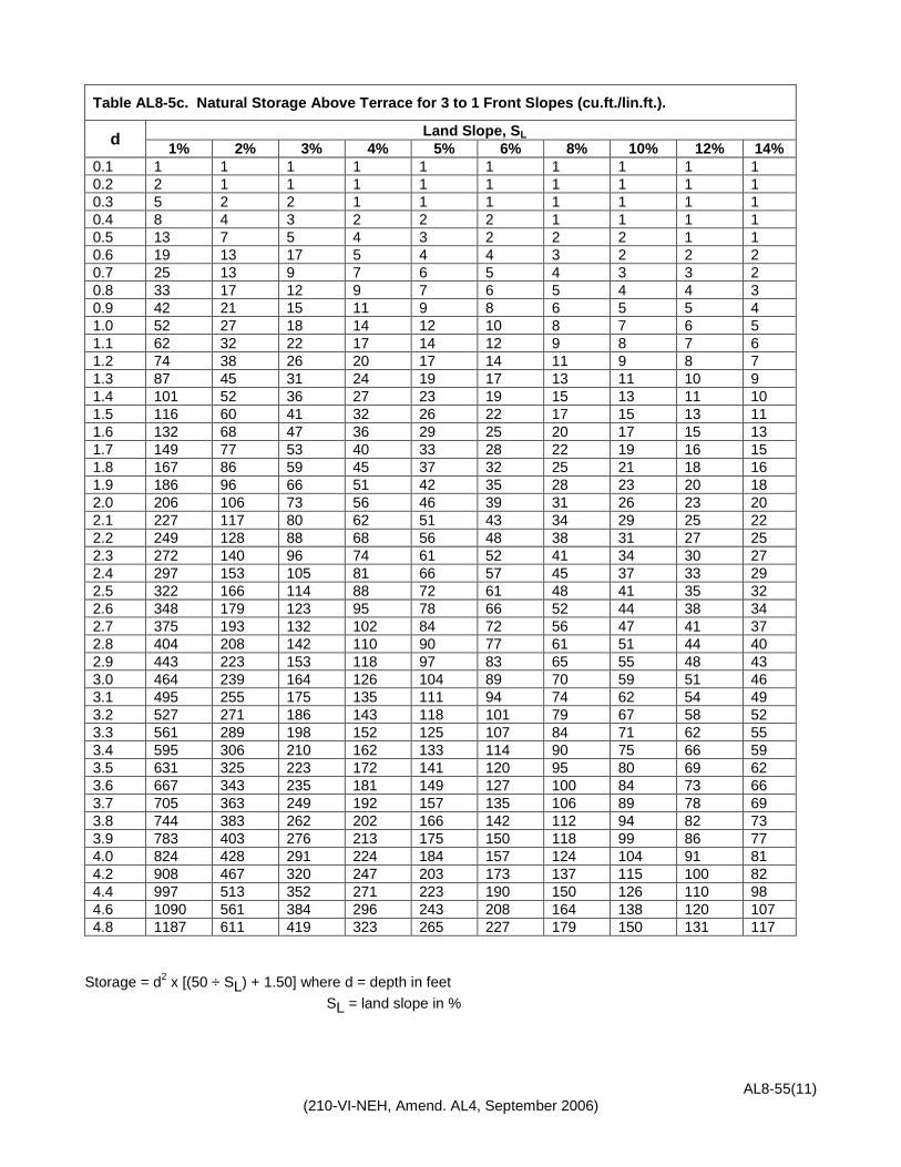
AL8-55(11) (210-VI-NEH, Amend. AL4, September 2006)
Storage = d2 x [(50 ÷ SL) + 1.50] where d = depth in feet SL = land slope in %
Table AL8-5c. Natural Storage Above Terrace for 3 to 1 Front Slopes (cu.ft./lin.ft.).
d Land Slope, SL 1% 2% 3% 4% 5% 6% 8% 10% 12% 14%
0.1 1 1 1 1 1 1 1 1 1 1 0.2 2 1 1 1 1 1 1 1 1 1 0.3 5 2 2 1 1 1 1 1 1 1 0.4 8 4 3 2 2 2 1 1 1 1 0.5 13 7 5 4 3 2 2 2 1 1 0.6 19 13 17 5 4 4 3 2 2 2 0.7 25 13 9 7 6 5 4 3 3 2 0.8 33 17 12 9 7 6 5 4 4 3 0.9 42 21 15 11 9 8 6 5 5 4 1.0 52 27 18 14 12 10 8 7 6 5 1.1 62 32 22 17 14 12 9 8 7 6 1.2 74 38 26 20 17 14 11 9 8 7 1.3 87 45 31 24 19 17 13 11 10 9 1.4 101 52 36 27 23 19 15 13 11 10 1.5 116 60 41 32 26 22 17 15 13 11 1.6 132 68 47 36 29 25 20 17 15 13 1.7 149 77 53 40 33 28 22 19 16 15 1.8 167 86 59 45 37 32 25 21 18 16 1.9 186 96 66 51 42 35 28 23 20 18 2.0 206 106 73 56 46 39 31 26 23 20 2.1 227 117 80 62 51 43 34 29 25 22 2.2 249 128 88 68 56 48 38 31 27 25 2.3 272 140 96 74 61 52 41 34 30 27 2.4 297 153 105 81 66 57 45 37 33 29 2.5 322 166 114 88 72 61 48 41 35 32 2.6 348 179 123 95 78 66 52 44 38 34 2.7 375 193 132 102 84 72 56 47 41 37 2.8 404 208 142 110 90 77 61 51 44 40 2.9 443 223 153 118 97 83 65 55 48 43 3.0 464 239 164 126 104 89 70 59 51 46 3.1 495 255 175 135 111 94 74 62 54 49 3.2 527 271 186 143 118 101 79 67 58 52 3.3 561 289 198 152 125 107 84 71 62 55 3.4 595 306 210 162 133 114 90 75 66 59 3.5 631 325 223 172 141 120 95 80 69 62 3.6 667 343 235 181 149 127 100 84 73 66 3.7 705 363 249 192 157 135 106 89 78 69 3.8 744 383 262 202 166 142 112 94 82 73 3.9 783 403 276 213 175 150 118 99 86 77 4.0 824 428 291 224 184 157 124 104 91 81 4.2 908 467 320 247 203 173 137 115 100 82 4.4 997 513 352 271 223 190 150 126 110 98 4.6 1090 561 384 296 243 208 164 138 120 107 4.8 1187 611 419 323 265 227 179 150 131 117

AL8-55(12) (210-VI-NEH, Amend. AL4, September 2006)
Table AL8-5c. Natural Storage Above Terrace for 3 to 1 Front Slopes (cu.ft./lin.ft.). (con't)
d Land Slope, SL 1% 2% 3% 4% 5% 6% 8% 10% 12% 14%
5.0 1288 663 454 350 288 246 194 168 142 127 5.2 1393 717 491 379 311 266 210 176 153 137 5.4 1502 773 530 408 335 287 226 190 165 148 5.6 1615 831 570 439 361 308 243 204 178 159 5.8 1732 891 611 471 387 331 261 219 191 171 6.0 1854 954 654 504 414 354 279 234 204 183 6.2 1980 1019 698 538 442 378 298 250 218 195 6.4 2109 1085 744 573 471 403 317 266 232 208 6.6 2243 1154 791 610 501 428 338 283 247 221 6.8 2381 1225 840 647 532 455 358 301 262 235 7.0 2524 1229 890 686 564 482 380 319 278 249 7.2 2670 1374 942 726 596 510 402 337 294 263 7.4 2820 1451 995 767 630 538 424 356 310 278 7.6 2975 1531 1049 809 664 568 448 375 327 293 7.8 3133 1612 1105 852 700 598 472 395 345 309 8.0 3296 1696 1163 896 736 629 496 416 363 325 8.2 3463 1782 1222 941 773 661 521 437 381 341 8.4 3634 1870 1282 988 811 694 547 459 400 358 8.6 3809 1960 1344 1035 851 727 573 481 419 375 8.8 3988 2052 1407 1084 891 761 600 503 439 393 9.0 4172 2147 1472 1134 932 797 628 527 459 411 9.2 4359 2243 1538 1185 973 832 656 550 480 429 9.4 4551 2342 1605 1237 1016 869 685 574 501 448 9.6 4746 2442 1674 1290 1060 906 714 599 522 467 9.8 4946 2545 1745 1345 1104 944 744 624 544 487 10.0 5150 2650 1817 1400 1150 983 775 650 567 507 10.2 5358 2757 1800 1457 1196 1023 806 676 590 528 10.4 5570 2866 1965 1514 1244 1064 838 703 613 543 10.6 5787 2978 2041 1576 1292 1105 871 730 637 570 10.8 6001 3091 2119 1633 1341 1147 904 758 661 592 11.0 6232 3207 2198 1694 1392 1190 938 787 686 614 11.2 6460 3324 2279 1756 1443 1233 972 815 711 636 11.4 6693 3444 2361 1819 1495 1278 1007 845 136 659 11.6 6930 3566 2445 1884 1547 1323 1043 875 763 682 11.8 7171 3690 2530 1949 1601 1369 1079 905 789 706 12.0 7416 3816 2616 2016 1656 1416 1116 936 816 730 12.2 7665 3944 2704 2084 1712 1464 1154 967 846 755

AL8-55(13) (210-VI-NEH, Amend. AL4, September 2006)
Table AL8-5d. Natural Storage Above Terrace for 2½ to 1 Front Slopes (cu.ft./lin.ft.).
d Land Slope, SL 1% 2% 3% 4% 5% 6% 8% 10% 12% 14%
0.1 1 1 1 1 1 1 1 1 1 1 0.2 2 1 1 1 1 1 1 1 1 1 0.3 5 2 2 1 1 1 1 1 1 1 0.4 8 4 3 2 2 2 1 1 1 1 0.5 13 7 4 3 3 2 2 2 1 1 0.6 18 9 6 5 4 3 3 2 2 2 0.7 25 13 9 7 6 5 4 3 3 2 0.8 33 17 11 9 7 6 5 4 3 3 0.9 42 21 15 11 9 8 6 5 4 4 1.0 52 26 18 14 11 10 8 6 5 5 1.1 62 32 22 17 14 12 9 8 7 6 1.2 74 38 26 20 16 14 11 9 8 7 1.3 87 44 30 23 19 16 13 11 9 8 1.4 100 51 35 27 22 19 15 12 11 9 1.5 115 59 40 31 25 22 17 14 12 11 1.6 131 67 46 35 29 25 19 16 14 12 1.7 148 76 52 40 33 28 22 18 16 14 1.8 166 85 58 45 36 31 24 20 18 16 1.9 185 95 65 50 41 35 27 23 20 17 2.0 205 105 72 55 45 38 30 25 22 19 2.1 226 116 79 61 50 42 33 28 24 21 2.2 248 127 87 67 54 46 36 30 26 23 2.3 271 139 95 73 60 51 40 33 29 26 2.4 295 151 103 79 65 55 43 36 31 28 2.5 320 164 112 86 70 60 47 39 34 30 2.6 346 177 121 93 76 65 51 42 37 33 2.7 374 191 131 100 82 70 55 46 39 35 2.8 402 206 140 108 88 75 59 49 42 38 2.9 431 221 151 116 95 81 63 53 46 41 3.0 461 236 161 124 101 86 38 56 49 43 3.1 493 252 172 132 108 92 72 60 52 46 3.2 525 269 183 141 115 98 77 64 55 49 3.3 558 286 195 150 123 104 82 68 59 53 3.4 592 303 207 159 130 111 87 72 63 56 3.5 628 322 219 168 138 117 92 77 66 59 3.6 664 340 232 178 146 124 97 81 70 62 3.7 702 359 245 188 154 131 103 86 74 66 3.8 740 379 259 199 162 138 108 90 78 70 3.9 780 399 273 209 171 146 114 95 82 73 4.0 820 420 287 220 180 153 120 100 87 77
Storage = d2 x [(50 ÷ SL) + 1.25] where d = depth in feet SL = land slope in %

AL8-55(14) (210-VI-NEH, Amend. AL4, September 2006)
Table AL8-5d. Natural Storage Above Terrace for 2½ to 1 Front Slopes (cu.ft./lin.ft.). (con't)
d Land Slope, SL 1% 2% 3% 4% 5% 6% 8% 10% 12% 14%
4.2 904 463 316 243 198 169 132 110 96 85 4.4 992 508 347 266 218 186 145 121 105 98 4.6 1084 555 379 291 238 203 159 132 115 102 4.8 1181 605 413 317 259 221 173 144 125 111 5.0 1281 656 448 344 281 240 188 156 135 121 5.2 1385 710 484 372 304 259 203 169 146 130 5.4 1494 465 522 401 328 279 219 182 158 141 5.6 1607 823 562 431 353 301 235 196 170 151 5.8 1724 883 603 463 378 322 252 210 182 162 6.0 1845 945 645 495 405 345 270 225 195 174 6.2 1970 1009 689 529 432 368 288 240 208 185 6.4 2099 1075 734 563 461 393 307 256 222 197 6.6 2232 1143 780 599 490 417 327 272 236 210 6.8 2370 1214 828 636 520 443 347 289 250 223 7.0 2511 1286 878 674 551 470 368 306 265 236 7.2 2657 1361 929 713 583 497 389 324 281 250 7.4 2806 1437 981 753 616 525 411 342 297 264 7.6 2960 1516 1035 794 650 554 433 361 313 278 7.8 3118 1597 1090 837 684 583 456 380 330 293 8.0 3280 1680 1147 880 720 613 480 400 347 309 8.2 3446 1765 1205 925 756 644 504 420 364 324 8.4 3616 1852 1264 970 794 676 529 441 382 340 8.6 3790 1941 1325 1017 832 709 555 462 401 357 8.8 3969 2033 1387 1065 871 742 581 484 419 373 9.0 4151 2126 1451 1114 911 776 608 506 439 391 9.2 4338 2222 1516 1164 952 811 635 529 458 408 9.4 4528 2319 1583 1215 994 847 663 552 479 426 9.6 4723 2419 1651 1267 1037 883 691 576 499 444 9.8 4922 2521 1721 1321 1080 920 720 600 520 463 10.0 5125 2625 1792 1375 1125 958 750 625 542 482 10.2 5332 2731 1864 1481 1170 997 780 650 564 502 10.4 5543 2839 1938 1487 1217 1037 811 676 586 521 10.6 5758 2949 2013 1545 1264 1077 843 702 609 542 10.8 5978 3062 2090 1604 1312 1118 875 729 632 562 11.0 6201 3176 2168 1664 1361 1160 908 756 655 583 11.2 6429 3293 2247 1725 1411 1202 941 784 679 605 11.4 6660 3411 2328 1787 1462 1245 975 812 704 627 11.6 6896 3532 2411 1850 1514 1290 1009 841 729 649 11.8 1736 3655 2495 1915 1566 1334 1044 870 754 671 12.0 7380 3780 2580 1980 1620 1380 1080 900 780 694 12.2 7628 3907 2667 2047 1674 1426 1116 930 806 718

AL8-55(15) (210-VI-NEH, Amend. AL4, September 2006)
DESIGN EXAMPLE - STORAGE TERRACE WITH UNDERGROUND OUTLET Determine the total required storage and the capacity of the underground outlet for a storage type terrace in Coffee County, Alabama. The land slope is 4 percent. Easily erodible soil with good cover and cropping system. Soils are hydrologic group B. Terrace will bypass over the top. Step 1 Determine horizontal interval: Existing Field Slope = 4% Broadbase and Grassed Ridge Backslope. HI = X(100) + y (100) s Use a "Y" factor of 4.0 with a good cropping system and good cover. x = 0.4 for South Alabama, HI = 140 ft. or select from Table AL8-1. Step 2 A. Determine present and future equipment row widths and number of rows (conference with landowner or
operator.) B. Determine farming width between terraces (See Table AL8-1). NOTE: Broadbase Terraces - The farming width is from the top of the upper terrace ridge to the top of
the lower terrace ridge. Grassed Steep Backslope Terraces - The farming width is from the toe of the backslope of the
upper terrace to the top of the ridge of the lower terrace. For grassed steep front and backslope terraces, use a minimum front slope of 1.5:1. Farming
width will be measured from backslope toe of the upper terrace to toe front slope of the lower terrace.
C. Determine the width of the terrace front slope. NOTE: The width of the terrace front slope should be equal to 1 or 2 passes of future farming
equipment. Solution: 1. Equipment width (conference with owner and operator). a. Existing equipment - 6 rows, 30 in. wide b. Future equipment - 8 rows, 30 in. wide
Number of Equipment Trips
Present Equipment 6 row, 30 in. width
(ft.)
Future 8 row, 30 in. width
(ft.) 1 15 20 2 30 40

AL8-55(16) (210-VI-NEH, Amend. AL4, September 2006)
2. Farming widths (See Table 8-1). A farming width of 120 ft. fits present and future equipment for 4 or 3 round trips. 3. Use a front slope = 20 ft. (1 pass of future farming equipment) Step 3 Determine terrace spacing. A. Broadbase terrace spacing (HI) is equal to the farming width. See Figure AL8-1. B. Grassed steep backslope terrace spacing (HI) is equal to the farming width plus the width of the
backslope. See Figure AL8-1. C. Grassed steep front and backslope terrace spacing (HI) is equal to the farming width plus the frontslope
and backslope. See Figure AL-1. NOTE: The HI can be increased or decreased up to 10% to fit future farm machinery and an additional
10% with underground outlets. Solution: 1. Broadbase Terraces (farming width) from Table AL8-1 = 120 feet. 2. Grassed steep backslope terraces Farming width = 120 ft. Adjust to fit equipment = 0 ft. Backslope width (approx.) = 6 ft. Terrace spacing (HI) = 126 ft. 3. Grassed steep front and backslope terraces. Farming width = 120 ft. Adjust to fit equipment = 0 ft. Front slope width = 6 ft. Backslope width (approx.) = 6 ft. Terrace spacing (HI) = 132 ft. Step 4 Determine storage requirements. Total storage for terrace 500 ft. long, spacing of 120 ft. A. Compute drainage area. 500 ft. terrace length 120 ft. terrace spacing Area = 500 ft. x 120 ft. / 43,560 sf/ac = 1.38 ac. B. Find runoff storage from Table AL8-2, to be 4.50 in. per unit of area.

AL8-55(17) (210-VI-NEH, Amend. AL4, September 2006)
C. 100% storage = 1.38 ac. x 4.50 in. = 6.21 ac.in. D. Assume a unstable bypass design with the minimum 33% storage. Required minimum storage = 0.33 x 6.21 ac.in. = 2.05 ac.in. Step 5 - Determine the bypass elevation that will provide the required minimum storage.
A. Assume a bypass elevation and compute the available natural storage in cu.ft./ft. by summing the values from Table AL8-5a, b, c, or d, multiply by the distance between rod readings and divide by 3,630 to obtain the available storage in acre-inches.
B. If less than 2.05 ac.in., the bypass will have to be raised, repeat step A.
Step 6 - Determine pipe size.
A. Calculate the required discharge in cfs for the pipe.
Using the multiplier factor of 3.0 from Table AL8-4, Q = 3.0 x 6.21 ac.in. = 18.63 ac.in. / 24 hr. Since 1 cfs = 23.802 ac.in. / 24 hr. Q = 18.63 / 23.802 = 0.78 cfs
B. Calculate the smooth pipe size from the formula on page 8-?.
D = (K x Q 0.375) /S 0.1875 = (2.9208 x 0.780.375)/0.040.1875 = 4.87” Use minimum 6” pipe.
Step 7 – Determine orifice size (if used). Use Formula A = Q/[C x (2gH) 0.5] A = 0.78/[0.6 x (64.4 x 3)0.5] = 0.0935 sf x 144 = 13.46 in2 Calculate a round opening with area = 13.46 in2
13.46 in2 / PI = 4.28 R = 4.280.5 = 2.07” D = 2.07 x 2 = 4.14 in. Use 4 1/4 “ Orifice Step 8 - Note This is an “over the top” unstable bypass terrace. The ridge elevation would be 0.5 ft.freeboard plus
10% settlement added to the bypass elevation. The ridge elevation would only be required for a short distance on either side of the pipe line. The remainder of the terrace could be built to the bypass elevation plus 10% settlement.

AL8-55(18) (210-VI-NEH, Amend. AL4, September 2006)
RECORDS AND MAINTENANCE
Engineering notes for terraces are to be recorded on Form SCE-ENG-29. Notes for storage terraces should be in accord with Figure AL8-4. When computer programs are used to design terraces, underground outlets and waterways, the printouts should be filed with the conservation plan. Notes for terraces with grassed waterways, field borders, and filter strip should be in accord with Figure AL8-5. Terrace capacity can be maintained generally by routine plowing. There is really no satisfactory way to plow terraced land except with the two-way (reversible) plow. With this plow, soil can be thrown either to the right or to the left depending upon choice. To maintain the cross section of the terraces and the terrace interval as it was after construction, most of the area should be plowed uphill. With the two-way plow, the front slope of each terrace should be plowed toward the ridge. The remaining area of the channel to the ridge of the next terrace generally should be plowed uphill. Maintenance of grassed ridge and grass back terraces is much easier than conventional terraces. Trees, brush, and grass can be controlled by spraying, mowing, or burning. Grass should be fertilized occasionally to maintain vigorous sod. Heavy equipment can also be used to perform terrace construction and maintenance.

Figure AL8-4. Terrace system with underground outlets survey notes and design. (Sheet 1 of 6)
Terraces with Underground Outlets
A. Engineering Surveys for Design and Construction Layout (SCS-ENG-191 Engineering Field Book) or (SCS-ENG-29)
1. Complete title page with sketch of practice location.
2. Show at beginning of survey; farmer’s name, purpose of survey, name of practice, party members, duties, and date.
3. Sketch showing location of each terrace with appropriate outlets.
4. Profile of proposed channel of each terrace, one terrace per page.
5. Profile of proposed pipe.
6. Concrete AL-ENG-21 or equivalent computer design for each terrace.
7. Table showing required discharge, pipe slope, and pipe size for each terrace.
B. Construction and Performance Checks (SCS-ENG-191 Engineering Field Book) or (SCS-ENG-29)
1. All terraces will be surveyed to determine that elevations are according to design.
2. A complete profile of the channel and ridge on at least one terrace per underground outlet will be recorded. Cross-section survey of at least one terrace in the system is required. A hand level survey is acceptable for this. Critical elevations and any potential problem areas should be checked and documented prior to approval of the system.
3. Table showing the constructed length of each terrace and total length of all terraces if the terraces are constructed at locations other than that laid out.
4. Supporting statements.
a. condition of outlets.
b. General remarks about construction meeting plans and specifications along with signature and dates. AL8-55(19)
(210-VI-NEH
, Amend. A
L4, September 2006)


Figure AL8-4. Terrace system with underground outlets survey notes and design. (Sheet 2 of 6)
AL8-55 (20) (210-VI-N
EH, Am
end. AL4, Septem
ber 2006)
U.S. Dept. of Agriculture AL-ENG-21 Natural Resources Conservation Service Rev. 5/06 DESIGN OF UNDERGROUND OUTLET (NOTE: References to tables and exhibits are found in the Alabama Engineering Field Design Manual, Chapter 8.)
LAND SLOPE = __4____ % AVG TERR SPACING = ___120____ FT. TERR FRONT SLOPE = __14__ FT. TYPE CHANNEL____V_______ D.A. = TER SP 120_ FT. X CHAN LGTH 600____ FT. = __1.65_ AC. 43560 REQ STORAGE(RS) = _____4.24________ IN. (From Table AL8-2) VOL STO REQ(VSR) = _4.24_ IN. X D.A. _1.65 AC. =_7.00 __ AC. IN. AVAIL STO(AS) = _183__FT3/FT. X _50_STA FT. = __2.52 AC. IN. 3630 BYPASS: ALONG CHAN OVER TERRACE____X______ % STOR = AS _2.52_ AC. IN. ÷ VSR _7.00___ AC. IN. =__36_____ % BYPASS EL = HI ___106.0_ - WL__9.7______ = ____96.3_________ RIDGE EL = BYPASS EL _96.3___ + F’BRD__0.5___ = __96.8_____ PIPE CAP = RS__4.24___ IN. X __2.78___ FACTOR = ___11.79__ IN. [“FACTOR” from Table AL8-4 for unstable bypass or % storage (expressed as decimal) for channel bypass.] PIPE SIZE = __6_ IN. MIN. DIA. NO. OF 1 IN. DIA. HOLES/FT = D.A._1.65_AC. X _PIPE CAP. 11.79 IN. = _29_ USE_30_____ 0.67 H = _2.2_ FT., Q__0.82_ CFS, ORIFICE DIA =__4.18___ IN. DESIGNED BY____C. Wise______ CHECKED BY__T. Nabors_____


Figure AL8-4. Terrace system with underground outlets survey notes and design. (Sheet 3 of 6)
AL8-55(21) (210-VI-N
EH, Am
end. AL4, Septem
ber 2006)
U.S. Dept. of Agriculture AL-ENG-21 Natural Resources Conservation Service Rev. 5/06 DESIGN OF UNDERGROUND OUTLET (NOTE: References to tables and exhibits are found in the Alabama Engineering Field Design Manual, Chapter 8.)
LAND SLOPE = __4____ % AVG TERR SPACING = ___120____ FT. TERR FRONT SLOPE = __14__ FT. TYPE CHANNEL____V_______ D.A. = TER SP 120_ FT. X CHAN LGTH 500____ FT. = __1.38_ AC. 43560 REQ STORAGE(RS) = _____4.24________ IN. (From Table AL8-2) VOL STO REQ(VSR) = _4.24_ IN. X D.A. _1.38 AC. =_5.84 __ AC. IN. AVAIL STO(AS) = _ 90__FT3/FT. X _50_STA FT. = __1.24 AC. IN. 3630 BYPASS: ALONG CHAN X OVER TERRACE___________ % STOR = AS _1.24_ AC. IN. ÷ VSR _5.84___ AC. IN. =__21_____ % BYPASS EL = HI ___106.0_ - WL__12.7 _____ = ____93.3_________ RIDGE EL = BYPASS EL _93.3___ + F’BRD__0.5___ = __93.8_____ PIPE CAP = RS__4.24___ IN. X __0.21___ FACTOR = ___0.89 __ IN. [“FACTOR” from Table AL8-4 for unstable bypass or % storage (expressed as decimal) for channel bypass.] PIPE SIZE = __8_ IN. MIN. DIA. NO. OF 1 IN. DIA. HOLES/FT = D.A._1.38_AC. X _PIPE CAP. 4.21 IN. = _8.7_ USE_12_____ 0.67 H = _2.6_ FT., Q__0.34_ CFS, ORIFICE DIA =__2.66___ IN. DESIGNED BY____C. Wise______ CHECKED BY__T. Nabors_____ Note: Pipe size includes Q from Terrace No. 1, used 100% of RS to size pipe.


Figure AL8-4. Terrace system with underground outlets survey notes and design. (Sheet 4 of 6)
AL8-55(22) (210-VI-N
EH, Am
end. AL4, Septem
ber 2006)


Figure AL8-4. Terrace system with underground outlets survey notes and design. (Sheet 5 of 6)
AL8-55(23) (210-VI-N
EH, Am
end. AL4, Septem
ber 2006)


Figure AL8-4. Terrace system with underground outlets survey notes and design. (Sheet 6 of 6)
AL8-55(24) (210-VI-N
EH, Am
end. AL4, Septem
ber 2006)


Figure AL8-5. Terrace system survey notes and design. (Sheet 1 of 3)
AL8-55(25) (210-VI-N
EH, Am
end. AL4, Septem
ber 2006)
Terraces
A. Engineering Surveys for Design and Construction Layout (SCS-ENG-191 Engineering Field Book) or (SCS-ENG-29)
1. Complete title page with sketch of practice location.
2. Show at beginning of survey; farmer’s name, purpose of survey, name of practice, party members, duties, and date.
3. Table showing terrace number, land slope, vertical or horizontal interval and layout length of each terrace.
4. Sketch showing location of each terrace with appropriate outlets.
B. Construction and Performance Checks (SCS-ENG-191 Engineering Field Book) or (SCS-ENG-29)
1. Normal survey check-out procedures are to make a profile and cross-section survey and record notes on at least one terrace in each group of terraces in each field. Experienced technicians may be approved by the engineer to make visual construction approval of the terrace profiles. It is recommended that visual approval be done after a runoff event. Cross-section survey of at least one terrace in the system is required. A hand level survey is acceptable for this. Critical elevations and any potential problem areas should be checked and documented prior to approval of the system.
2. Table showing the constructed length of each terrace and total length of all terraces if the terraces are constructed at locations other than that laid out.
3. Supporting statements.
a. condition of outlets.
b. General remarks about construction meeting plans and specifications along with signature and dates.


Figure AL8-5. Terrace System Survey Notes and Design. (Sheet 2 of 3)
AL8-55(26) (210-VI-N
EH, Am
end. AL4, Septem
ber 2006)


Figure AL8-5. Terrace System Survey Notes and Design. (Sheet 3 of 3)
AL8-55(27) (210-VI-N
EH, Am
end. AL4, Septem
ber 2006)