akd™ usingakdethernet/ipwithrslogix manualcga/akd/903-200009-00 akd_ethernet... ·...
TRANSCRIPT

AKD™
Using AKD EtherNet/IP with RSLogixManual
Edition October, 2011, Revision A
Valid for Hardware Revision C
Patents Pending
Part Number 903-200009-00
Keep allmanuals asa product component during the life span of the product.Passallmanuals to future users/ownersof the product.

Ethernet IP with RSLogix |
Record of Document Revisions:
Revision RemarksA, 10/2011 Launch version
EtherNet/IP is a registered trademark of ODVA, Inc.WINDOWS is a registered trademark of Microsoft CorporationAKD is a registered trademark of Kollmorgen™Corporation
Technical changes which improve the performance of the device may be made without priornotice.
Printed in the United States of AmericaThis document is the intellectual property of Kollmorgen™. All rights reserved. No part of this work maybe reproduced in any form (by photocopying, microfilm or any other method) or stored, processed, copiedor distributed by electronic means without the written permission of Kollmorgen™.
Kollmorgen™ | October, 2011 2

This page intentionally left blank.
3 Kollmorgen™ | October, 2011

Ethernet IP with RSLogix |
Table of Contents1 Introduction 81.1 Add-On Instructions 8
2 AKD Installation and Setup 93 Quick Start with the AKD Sample Project 103.1 Setup 103.2 Running the Main Program Loop 143.2.1 Test Sequence 14
3.3 Testing Individual Instructions 154 Adding AKD Support to a New or Existing Project 174.1 Adding the Ethernet IO Module for AKD Communication 174.2 Importing the AKD Add-On Instructions to a Project 214.3 Using the AKD Add-On Instructions in a Project 264.4 Reading and Writing Drive Parameters 30
5 AKD Instructions 325.1 Motion Axis Drive Communication (AKD_Drive) 325.1.1 Description 325.1.2 Operands 325.1.3 AKD_DRIVE Structure 325.1.4 Execution 325.1.5 Changes to Axis Status Bits 32
5.2 Motion Axis On (AKD_Enable) 335.2.1 Description 335.2.2 Operands 335.2.3 AKD_ENABLE Structure 335.2.4 Execution 335.2.5 Changes to Axis Status Bits 34
5.3 Motion Axis Off (AKD_Disable) 355.3.1 Description 355.3.2 Operands 355.3.3 AKD_DISABLE Structure 355.3.4 Execution 355.3.5 Changes to Axis Status Bits 36
5.4 Motion Axis Home (AKD_Home) 375.4.1 Description 375.4.2 Operands 375.4.3 AKD_HOME Structure 375.4.4 Execution 385.4.5 Changes to Axis Status Bits 38
5.5 Motion Axis Jog (AKD_Jog) 395.5.1 Description 395.5.2 Operands 39
Kollmorgen™ | October, 2011 4

Ethernet IP with RSLogix |
5.5.3 AKD_JOGStructure 395.5.4 ProgrammingGuidelines 405.5.5 Execution 405.5.6 Changes to Axis Status Bits 40
5.6 Motion Axis Move (AKD_Move) 415.6.1 Description 415.6.2 Operands 415.6.3 AKD_MOVE Structure 415.6.4 ProgrammingGuidelines 425.6.5 Choosing aMove Type 425.6.6 Execution 425.6.7 Changes to Axis Status Bits 42
5.7 Motion Axis Set Home Mode (AKD_Set_Home_Mode) 435.7.1 Description 435.7.2 Operands 435.7.3 AKD_SET_HOME_MODE Structure 445.7.4 HomingModes 445.7.5 Execution 445.7.6 Changes to Axis Status Bit 44
5.8 Motion Axis Set Acceleration (AKD_Set_Accel) 455.8.1 Description 455.8.2 Operands 455.8.3 AKD_SET_ACCEL Structure 455.8.4 Execution 455.8.5 Changes to Axis Status Bits 46
5.9 Motion Axis Set Deceleration (AKD_Set_Decel) 475.9.1 Description 475.9.2 Operands 475.9.3 AKD_SET_DECEL Structure 475.9.4 Execution 475.9.5 Changes to Axis Bits 48
5.10 Motion Axis Set Mode (AKD_Set_Mode) 495.10.1 Description 495.10.2 Operands 495.10.3 AKD_SET_MODE Structure 495.10.4 OperationModes 495.10.5 Execution 505.10.6 Changes to Axis Status Bits 50
5.11 Motion Axis Set Position (AKD_Set_Position) 515.11.1 Description 515.11.2 Operands 515.11.3 AKD_SET_POSITION Structure 515.11.4 Execution 525.11.5 Changes to Axis Status Bits 52
5 Kollmorgen™ | October, 2011

Ethernet IP with RSLogix |
5.12 Motion Axis Set Velocity (AKD_Set_Velocity) 535.12.1 Description 535.12.2 Operands 535.12.3 AKD_SET_VELOCITY Structure 535.12.4 Execution 545.12.5 Changes to Axis Status Bits 54
5.13 Motion Axis Shutdown (AKD_Shutdown) 555.13.1 Description 555.13.2 Operands 555.13.3 AKD_SHUTDOWN Structure 555.13.4 Execution 565.13.5 Changes to Axis Status Bits 56
5.14 Motion Axis Shutdown Reset (AKD_Shutdown_Reset) 575.14.1 Description 575.14.2 Operands 575.14.3 AKD_SHUTDOWN_RESET Structure 575.14.4 Execution 575.14.5 Changes to Axis Status Bits 58
5.15 Motion Axis Smooth Stop (AKD_Stop_Smooth) 595.15.1 Description 595.15.2 Operands 595.15.3 AKD_STOP_SMOOTH Structure 595.15.4 Execution 595.15.5 Changes to Axis Status Bits 59
5.16 Motion Axis Get Position Controller Attribute (AKD_Get_Attribute) 605.16.1 Description 605.16.2 Operands 605.16.3 AKD_GET_ATTRIBUTE Structure 605.16.4 Execution 605.16.5 Changes to Axis Status Bits 61
5.17 Motion Axis Set Position Controller Attribute (AKD_Set_Attribute) 625.17.1 Description 625.17.2 Operands 625.17.3 AKD_SET_ATTRIBUTE Structure 625.17.4 Execution 625.17.5 Changes to Axis Status Bits 62
5.18 Motion Axis Set Parameter (AKD_Set_Parameter) 635.18.1 Description 635.18.2 Operands 635.18.3 AKD_SET_PARAMETER STRUCTURE 635.18.4 Execution 635.18.5 Changes to Axis Status Bits 63
5.19 Motion Axis Set Units (AKD_Set_Units) 645.19.1 Description 64
Kollmorgen™ | October, 2011 6

Ethernet IP with RSLogix |
5.19.2 Operands 645.19.3 AKD_SET_UNITS Structure 645.19.4 Execution 645.19.5 Changes to Axis Status Bits 64
6 Troubleshooting 657 Appendix A: Supported EtherNet/IP Objects and Attributes 667.1 Position Controller Class 0x25 66
8 Appendix B Parameter Listing 67
7 Kollmorgen™ | October, 2011

Ethernet IP with RSLogix | 1 Introduction
1 IntroductionThis manual provides an easy start guide for using AKD with RSLogix, an overview on how to import andconfigure the AKD Add-On instructions using RSLogix5000 version 16 or later, as well as a reference tothe Add-On instructions.
On our website, www.kollmorgen.com, you can find RSLogix sample projects and add-on instructions,which demonstrate an EtherNet/IP network with a CompactLogix controller and the AKD.
The sample projects are based on an L32E CompactLogix controller, which easily can be changed toanother controller which supports RSLogix.
This document assumes that the reader has a basic knowledge of EtherNet/IP protocols, AKD drives,and Rockwell RSLogix5000.
1.1 Add-On Instructions
The AKD Add-On Instructions are RSLogix instructions that define AKD drives and axis configurations.These instructions aremade to be imported into an RSLogix5000 project. Once defined in a project, theyfunction just as a native RSLogix instruction. The add-on instructions encapsulate themost commonlyused logic for AKD axes. They provide easily reusable tools to operate drives and axes, promoting con-sistency across different projects.
Note that the nativeMSG instruction is used in RSLogix for sending Explicit Messages.
A set of Add-On instructions are provided for easy creation of AKD programs with RSLogix. The instruc-tions are written tomirror the native instructions, leveraging existing knowledge of the software. They pro-vide easy control of IO Assembly messages.
Add-On Instructions include:
l AKD_Enablel AKD_Disablel AKD_Homel AKD_Jogl AKD_Movel AKD_Set_Home_Model AKD_Set_Model AKD_Shutdownl AKD_Shutdown_Resetl AKD_Stop_Smoothl AKD_Get_Attributel AKD_Get_Parameterl AKD_Set_Attributel AKD_Set_Parameterl AKD_Set_Units
Kollmorgen™ | October, 2011 8

Ethernet IP with RSLogix | 2 AKD Installation and Setup
2 AKD Installation and SetupSee the followingmanuals for installation and setup of an AKD drive:
l AKD Quick Start (also available in hard copy). This guide provides instructions for basic drivesetup and connection to a network.
l AKD InstallationManual (also available in hard copy). This manual provides instructions for instal-lation and drive setup.
l AKD Parameter and CommandReferenceGuide. This guide provides documentation for theparameters and commands used to program the AKD
l AKDEtherNet/IP Communication Guide. This guide describes the communication profile and useof EtherNet/IP with the AKD.
9 Kollmorgen™ | October, 2011

Ethernet IP with RSLogix | 3 Quick Start with the AKD Sample Project
3 Quick Start with the AKD Sample ProjectThe sample project AKD_Sample_Project.ACD demonstrates the correct setup of an axis and runs a pro-gram loop which demonstrates point-to-point positionmoves, motion tasking control, and jogging.
This project can help you to learn:
l how to enable the drivel how to write/read a parameter via the acyclic channell how the cyclic data exchange is donel how to runmotion in position or velocity model how to clear faultsl how to load and executemotion task sequences
3.1 Setup1. Start RSLogix5000 and open the file AKD_Sample_Project.ACD in the installer directory.2. You will most likely need to update the controller properties tomatch your specific installation.
Right click on the controller (“AKD_Controller”) at the top of the tree and select “Properties”(Figure 3 1: Opening Controller Properties).
a. Note that you can also use the Controller Properties button located above the tree.
Figure 3-1: Opening Controller Properties
Kollmorgen™ | October, 2011 10

Ethernet IP with RSLogix | 3 Quick Start with the AKD Sample Project
3. Update any controller properties in order for the controller to match your specific hardware setup,most notably any communication settings and/or the controller type, and then close the controllerproperties window (Figure 3 2: Controller Properties).
Figure 3-2: Controller Properties
11 Kollmorgen™ | October, 2011

Ethernet IP with RSLogix | 3 Quick Start with the AKD Sample Project
4. Next, open the Ethernet-Module setup for the axis’ communications by right clicking on “ETH-ERNET-MODULE AKD_Axis” in the “I/O Configuration” tree under the Ethernet port (Figure 3 3:Opening Ethernet Module Properties).
Figure 3-3: Opening Ethernet Module Properties
Kollmorgen™ | October, 2011 12

Ethernet IP with RSLogix | 3 Quick Start with the AKD Sample Project
5. Update any specific module properties in order for themodule tomatch your specific hardwaresetup, most notably the IP address, and then close themodule properties window (Figure 3 4: Eth-ernet Module Properties).
Figure 3-4: Ethernet Module Properties
6. Once you have updated all of the configuration settings tomatch your specific hardware setup, youcan download the program to the controller and use the project to test any of the axis commands.
13 Kollmorgen™ | October, 2011

Ethernet IP with RSLogix | 3 Quick Start with the AKD Sample Project
3.2 Running the Main Program Loop
The top level of the program is in the subroutine “Tasks > MainTask > MainProgram > MainRoutine.”
The sample program has twomodes. When the tag Active_Command.Control_Mode=0, the program issetup to execute a continuous test loop. The secondmode (tag value=1) is used for testing individual com-mands, and is described in the next section of themanual.
To begin executing the continuous test loop, set the tag Active_Command.Control_Mode=0, then set thetagMain_Sequence_Step = 1.
Figure 3-5: Main Program of AKD Sample Project
3.2.1 Test Sequence
Step 1: Setup sequence tags for test subroutines.
Step 2: Initialization_Sequence.
1. Disable and clear faults2. Set units to default3. Demonstrate how to set a drive configuration value using the cyclic message channel4. Read the value back and verify correctness5. Set homingmode to default (set current position as home)6. Enable the drive
Step 3: Position_Move_Sequence
1. Set operationmode to Position2. Home the axis3. Make a forward absolution positionmove4. Check actual position using status data from the cyclic message5. Make a reverse incremental move
Kollmorgen™ | October, 2011 14

Ethernet IP with RSLogix | 3 Quick Start with the AKD Sample Project
Step 4: Load_Motion_Tasks
1. Load twomotion tasks from a controller data structure into the drive. Motion task 1 is configured toexecutemotion task 2 after it completes.
2. Executemotion task 13. Confirm that bothmotion tasks execute properly
Step 5: Jog_Move_Sequence
1. Set operationmode to velocity2. Jog forward 500ms3. Read torque using an explicit message (MSG instruction)4. Perform hard stop5. Clear hard stop and enable6. Jog reverse 1000ms7. Check target velocity and confirm8. Check actual velocity is in range9. Stop
Step 6: Loop to step 1
3.3 Testing Individual Instructions
All of the instruction calls are in the Kollmorgen_AOIs subroutine, which you can open from “Tasks > MainTask > MainProgram > Kollmorgen_AIOs” (Figure 3 5: AKD Instruction Subroutine).
To test individual instructions, set the tag Active_Command.Control_Mode=1 so that the Kollmorgen_AOIs subroutine will be called fromMainRoutine.
Make sure to review “Chapter 5: AKD Instructions” below for a complete understanding of the instructionsand their operation before executing any instructions in the example program.
Figure 3-5: AKD Instruction Subroutine
15 Kollmorgen™ | October, 2011

Ethernet IP with RSLogix | 3 Quick Start with the AKD Sample Project
All of the instructions have their own individual trigger coils. To call an instruction, toggle its trigger coil(Figure 3 6: Toggling a Trigger Coil)
Figure 3-6: Toggling a Trigger Coil
Kollmorgen™ | October, 2011 16

Ethernet IP with RSLogix | 4 Adding AKD Support to a New or Existing Project
4 Adding AKD Support to a New or ExistingProject
4.1 Adding the Ethernet IO Module for AKD Communication
These basic instructions can be used for any Rockwell PLC that uses RSLogix5000 and supports Eth-erNet/IP.
1. Start RSLogix5000 and open the project with which you want to use the AKD drive.2. Right click on the Ethernet port in the I/O Configuration and select “New Module…” (Figure 4 1:
Adding New Module)
Figure 4-1: Adding New Module
17 Kollmorgen™ | October, 2011

Ethernet IP with RSLogix | 4 Adding AKD Support to a New or Existing Project
3. Select “ETHERNET-MODULE” under “Communications” and click OK (Figure 4 2: SelectingMod-ule Type)
Figure 4-2: Selecting Module Type
Kollmorgen™ | October, 2011 18

Ethernet IP with RSLogix | 4 Adding AKD Support to a New or Existing Project
4. Enter the settings for the new module as described below, make sure the “OpenModule Prop-erties” checkbox is checked, and click OK (Table 4 1: Module Setting Values & Figure 4 3: EnteringModule Settings)
Field ValueName AKD_DriveDescription Text description for driveComm Format Data--SINTIP Address Ethernet IP address for driveInput Assembly Instance 102Input Size 64Output Assembly Instance 101Output Size 64Configuration Assembly Instance 100Configuration Size 0
Table 4-1: Module Setting Values
Figure 4-3: Entering Module Settings
5. The “New Module” window now appears as a “Module Properties: ENB” window with the Con-nection tab selected. Set the “Requested Packet Interval (RPI)” value to 20.0ms (this can bereduced to 10.0ms when not usingWorkbench in combination with EtherNet/IP). If an option “UseUnicast Connection over EtherNet/IP” is visible, make sure it is unchecked. Click OK. (Figure 4 4:SettingModule RPI).
19 Kollmorgen™ | October, 2011

Ethernet IP with RSLogix | 4 Adding AKD Support to a New or Existing Project
Figure 4-4: Setting Module RPI
6. The drive should now be configured and will show up under the Ethernet Port (Figure 4 5: ModuleSuccessfully Added to Project)
Figure 4-5: Module Successfully Added to Project
Kollmorgen™ | October, 2011 20

Ethernet IP with RSLogix | 4 Adding AKD Support to a New or Existing Project
7. Make sure that the Ethernet port for your controller is setup with a compatible IP address on thesame subnet. This can be configured by right-clicking on 1769-L23E-QB1 Ethernet Port Local andselecting properties. See your controller user manual for more information.
4.2 Importing the AKD Add-On Instructions to a Project
Important: The User Defined Data Types must be imported before the Add-On Instructions.
1. Right click the “User-Defined” folder under “Data Types” and select “Import Data Type…” (Figure 46: Importing Data Types)
Figure 4-6: Importing Data Types
21 Kollmorgen™ | October, 2011

Ethernet IP with RSLogix | 4 Adding AKD Support to a New or Existing Project
2. Browse to the location of the AKD User Defined Data Type library and select thedesired User Defined Data Type then click “Import…” (Figure 4 7: Selecting a UDT)
a. Import the data types in the order show in Table 4 2: UDT Import Order.
Figure 4-7: Selecting a UDT
Order File Descrption1 AKD_Control_UDT.L5X Control message for sending to axis2 AKD_Status_UDT.L5X Status message for updating from axis3 AKD_Axis_UDT.L5X Axis definition4 Motion_Task_UDT.L5X Motion Task data table structure
Table 4-2: UDT Import Order
3. Click OK on the import configuration dialog, if one appears. Repeat for all files in “Table 4 2: UDTImport Order” to import all of the needed data types
Kollmorgen™ | October, 2011 22

Ethernet IP with RSLogix | 4 Adding AKD Support to a New or Existing Project
4. The data types should now show up under the “Data Types > User-Defined” folder (Figure 4 8:Data Types Successfully Imported)
Figure 4-8: Data Types Successfully Imported
5. Next, to import the add-on instructions, right click on the “Add-On Instructions” folder and select“Import Add-On Instruction…” (Figure 4 9: Importing Add-On Instructions)
Figure 4-9: Importing Add-On Instructions
23 Kollmorgen™ | October, 2011

Ethernet IP with RSLogix | 4 Adding AKD Support to a New or Existing Project
6. Browse to the location of the AKD AddOn Instruction library and select the desired AOI then click“Import…” (Figure 4 10: Selecting an AOI)
a. For complete functionality, import all of the files listed in “Table 4 3: All AddOn Instruc-tions”
Figure 4-10: Selecting an AIO
File DescriptionAKD_Disable_AOI.L5X Motion Axis OffAKD_Drive_AOI.L5X Drive CommunicationAKD_Enable_AOI.L5X Motion Axis OnAKD_Fault_Reset_A
OI.L5XMotion Axis Fault Reset
AKD_Get_Attribute_AOI.L5X Get Axis AttributeAKD_Get_Parameter_AOI.L5X Get Axis ParameterAKD_Home_AOI.L5X Motion Axis HomeAKD_Jog_AOI.L5X Motion Axis JogAKD_Move_AOI.L5X Motion Axis MoveAKD_Set_Accel_AOI.L5X Motion Axis Set AccelerationAKD_Set_Attribute_AOI.L5X Set Axis AttributeAKD_Set_Decel_AOI.L5X Motion Axis Set DecelerationAKD_Set_Home_Mode_AOI.L5X Motion Axis Set HomeMode
Kollmorgen™ | October, 2011 24

Ethernet IP with RSLogix | 4 Adding AKD Support to a New or Existing Project
File DescriptionAKD_Set_Mode_AOI.L5X Motion Axis Set ModeAKD_Set_Parameter_AOI.L5X Set Axis ParameterAKD_Set_Position_AOI.L5X Motion Axis Set PositionAKD_Set_Units_AOI.L5X Motion Axis Set UnitsAKD_Set_Velocity_AOI.L5X Motion Axis Set VelocityAKD_Shutdown_AOI.L5X Motion Axis ShutdownAKD_Shutdown_Reset_AOI.L5X Motion Axis ShutdownResetAKD_Stop_Smooth_AOI.L5X Motion Axis Smooth Stop
Table 4-3: All Add On Instructions
7. Click OK on the import dialog, if any appear. Repeat for all files in “Table 4 3: All AddOn Instruc-tions” to import all of the needed instructions for full functionality
8. The instructions should now show up under the “Add-On Instructions” folder (Figure 4 11: AOI’sSuccessfully Imported)
Figure 4-11: AOI's Successfully Imported
25 Kollmorgen™ | October, 2011

Ethernet IP with RSLogix | 4 Adding AKD Support to a New or Existing Project
4.3 Using the AKD Add-On Instructions in a Project
In any project where you want to use the AKD Add-On instructions, you will need to include one instanceof the Drive Communication logic for each axis (AKD_Drive instruction).
1. Add the AKD_Drive instruction to your ladder diagram.
Figure 4-17: AKD_Drive Instruction Tags
2. Right click the AKD_Drive parameter (first questionmark) in the AKD_Drive instruction, and selectNew Tag…
Figure 4-12: Add New Instruction Tag
Kollmorgen™ | October, 2011 26

Ethernet IP with RSLogix | 4 Adding AKD Support to a New or Existing Project
3. Fill in a name and description. The data type should be AKD_Drive.
Figure 4-13: Adding Drive Communication
4. Click OK in the New Tagwindow to create your tag. It will now show up in your controller under“Controller Tags”
Figure 4-15: Tag Added to Program
27 Kollmorgen™ | October, 2011

Ethernet IP with RSLogix | 4 Adding AKD Support to a New or Existing Project
5. Repeat steps 2-4 to add a new tag to the Axis_Internal parameter of the instruction, with a datatype of AKD_Axis.
Figure 4-21: Adding Axis_Internal Parameter
6. Set the Axis_Input parameter to the input data of the axis for which you are setting up com-munication (Figure 4 18: Axis Communication Input). The input data tag corresponds to the “ETH-ERNET-MODULE” object you created in the I/O Configuration of the project.
Figure 4-18: Axis Communication Input
Kollmorgen™ | October, 2011 28

Ethernet IP with RSLogix | 4 Adding AKD Support to a New or Existing Project
7. Set the Axis_Output parameter to the output data of the axis for which you are setting up com-munication (Figure 4 19: Axis Communication Output). The output data tag corresponds to the“ETHERNET-MODULE” object you created in the I/O Configuration of the project.
Figure 4-19: Axis Communication Output
8. Once you have configured the drive communication block, you should be able to use any of theother AKD Add-On instructions as you would the native RSLogix instructions.
9. For more information on each instruction, see “Section 5: AKD Instructions” below.
29 Kollmorgen™ | October, 2011

Ethernet IP with RSLogix | 4 Adding AKD Support to a New or Existing Project
4.4 Reading and Writing Drive Parameters
In addition to the Add-On instructions listed in this manual, almost all drive parameters can be read or setthrough the use of aMSG instruction.
Appendix B provides a list of parameters which are available.
To read a parameter, create aMSG instruction with the following settings:
Field ValueMessage Type CIP GenericService Type Parameter ReadService Code e (Hex)Class f (Hex)Instance Parameter Instance from Appendix BAttribute 1Destination Create a tag to hold the valueCommunication > Path Name of the ETHERNET-MODULE for the AKD axis. Use the Browse button.
Kollmorgen™ | October, 2011 30

Ethernet IP with RSLogix | 4 Adding AKD Support to a New or Existing Project
To set a parameter, create aMSG instruction with the following settings:
Field ValueMessage Type CIP GenericService Type ParameterWriteService Code 10 (Hex)Class f (Hex)Instance Parameter Instance from Appendix BAttribute 1Source Element Create a tag to hold the valueSource Length Parameter size from Appendix BCommunication > Path Name of the ETHERNET-MODULE for the AKD axis. Use the Browse button.
To execute a command, create aMSG instruction to write to the command:
Field ValueMessage Type CIP GenericService Type ParameterWriteService Code 10 (Hex)Class f (Hex)Instance Parameter Instance from Appendix BAttribute 1Source Element Create a tag to hold the value. Any actual valuemay be used - it is ignored.Source Length 1 byteCommunication > Path Name of the ETHERNET-MODULE for the AKD axis. Use the Browse button.
31 Kollmorgen™ | October, 2011

Ethernet IP with RSLogix | 5 AKD Instructions
5 AKD Instructions
5.1 Motion Axis Drive Communication (AKD_Drive)
5.1.1 Description
Use themotion axis drive communication (AKD_Drive) instruction to initiate communication for an axis.This command is required for all other AKD commands to function properly.
5.1.2 OperandsOperand Type Format DescriptionAKD_Drive AKD_DRIVE Tag Control tag for this instruction.Axis_Input AB:ETHERNET_MODULE_SINT_8Bytes:I:0 Tag Input memory space for axis.Axis_Output AB:ETHERNET_MODULE_SINT_8Bytes:O:0 Tag Output memory space for axis.Axis_Internal AKD_AXIS Tag The name of the axis to initialize.
This tag is an input parameter forall AKD instructions.
5.1.3 AKD_DRIVE StructureMnemonic Data
TypeDescription
.EnableIn BOOL The enable input bit indicates that the instruction is enabled. It remains set untilthe instruction completes and the rung-condition-in goes false.
.EnableOut BOOL The enable output bit is the output of the enable input bit.
5.1.4 ExecutionCondition Ladder Diagram ActionInstruction execution Read responsemessage and send commandmessage
to axis.
5.1.5 Changes to Axis Status BitsBit Name MeaningAll All axis status bits are updated from drive.
Kollmorgen™ | October, 2011 32

Ethernet IP with RSLogix | 5 AKD Instructions
5.2 Motion Axis On (AKD_Enable)
5.2.1 Description
TheMotion Axis On (AKD_Enable) instruction directly activates the drive and enables the configuredservo loops associated with a physical servo axis. It can be used anywhere in a program. Corresponds totheMSO instruction in Rockwell drives.
The AKD_Enable instruction automatically enables the specified axis by activating the drive and by acti-vating the associated servo loop.
Themost common use of this instruction is to activate the servo loop for the specified axis in its currentposition in preparation for commandingmotion.
The AKD_Enable instruction executionmay takemultiple scans to executebecause it requires transmission of amessage to themotionmodule and time forthe drive output to stabilize and the servo loop to activate. The Done (.DN) bit isnot set immediately, but only after the axis is in the Enabled state.
5.2.2 OperandsOperand Type Format DescriptionAKD_Enable AKD_ENABLE Tag Control tag for this instruction.Axis AKD_AXIS Tag The name of the axis to enable.
5.2.3 AKD_ENABLE StructureMnemonic Data Type Description.EnableIn BOOL The enable input bit indicates that the instruction is enabled. It remains set
until the instruction completes and the rung-condition-in goes false..EnableOut BOOL The enable output bit is the output of the enable input bit..DN (Done) BOOL The done bit indicates when the enable instruction completes..ER (Error) BOOL The error bit indicates if the instruction detects an error..Axis AKD_AXIS The axis being enabled.
5.2.4 ExecutionCondition Ladder Diagram ActionPrescan Initialize variables and clear timeout.Rung-condition-in isfalse
Initialize variables and clear timeout.
Instruction execution Set enable bit in the commandmessage to the drive if the drive does nothave any faults. Then, set the done bit when the enabled response isreturned. If the drive has a general fault or there is a communication time-out, set the error bit.
33 Kollmorgen™ | October, 2011

Ethernet IP with RSLogix | 5 AKD Instructions
5.2.5 Changes to Axis Status BitsBit Name State MeaningEnable True Axis is in Enabled state with the servo loop active.
Kollmorgen™ | October, 2011 34

Ethernet IP with RSLogix | 5 AKD Instructions
5.3 Motion Axis Off (AKD_Disable)
5.3.1 Description
TheMotion Axis Off (AKD_Disable) instruction directly and immediately turns off drive output and dis-ables the servo loop on any physical servo axis. This places the axis in the Disabled state. The AKD_Dis-able instruction also disables any motions that may be active at the time of execution. Corresponds to theMSF instruction in Rockwell drives.
The AKD_Disable instruction requires no parameters - simply enter the desired axis. Use the Tag Editorto create and configure a new axis.
You can use the AKD_Disable instruction to turn servo action OFF when youmust move the axis byhand. Since the position continues to be tracked even with the servo action Off, when the servo loop isturnedOn again by the AKD_Enable instruction, the axis is again under closed-loop control, at the newposition.
The AKD_Disable instruction executionmay takemultiple scans to executebecause it requires transmission of amessage to themotionmodule and time forthe drive output and servo loop to be fully deactivated. The Done (.DN) bit is notset until this message has been successfully transmitted and the axis transitionsto the Disabled state.
5.3.2 OperandsOperand Type Format DescriptionAKD_Disable AKD_DISABLE Tag Control tag for this instruction.Axis AKD_AXIS Tag The name of the axis to disable.
5.3.3 AKD_DISABLE StructureMnemonic Data Type Description.EnableIn BOOL The enable input bit indicates that the instruction is enabled. It remains set
until the instruction completes and the rung-condition-in goes false..EnableOut BOOL The enable output bit is the output of the enable input bit..DN (Done) BOOL The done bit indicates when the disable instruction completes..ER (Error) BOOL The error bit indicates if the instruction detects an error..Axis AKD_AXIS The axis being disabled.
5.3.4 ExecutionCondition Ladder Diagram ActionPrescan Initialize variables and clear timeout.Rung-condition-in isfalse
Initialize variables and clear timeout.
Instruction execution Reset enable bit in the commandmessage to the drive. Then, set thedone bit when the disabled response is returned. If the drive has a gen-eral fault or there is a communication timeout, set the error bit.
35 Kollmorgen™ | October, 2011

Ethernet IP with RSLogix | 5 AKD Instructions
5.3.5 Changes to Axis Status BitsBit Name State MeaningEnable False Axis is in Disabled state with the servo loop active.
Kollmorgen™ | October, 2011 36

Ethernet IP with RSLogix | 5 AKD Instructions
5.4 Motion Axis Home (AKD_Home)
5.4.1 Description
TheMotion Axis Home (AKD_Home) instruction triggers the axis to home using the currently configuredhomingmode. See the AKD user manual for homingmodes and setting instructions. This commandtriggers the drive to start the procedure andmonitors for the process to complete. Similar to theMAHinstruction in Rockwell drives.
Drivemust be enabled in order to execute this instruction.
This is a transitional instruction:
l In ladder diagram, toggle the rung-condition-in from cleared to set each time the instruction shouldexecute.
The AKD_HOME instruction executionmay takemultiple scans to executebecause it requires transmission of amessage to themotionmodule and time forthe drive to perform the homing procedure.
5.4.2 OperandsOperand Type Format DescriptionAKD_Home AKD_HOME Tag Control tag for this instruction.Axis AKD_AXIS Tag The name of the axis to home.
5.4.3 AKD_HOME StructureMnemonic Data
TypeDescription
.EnableIn BOOL The enable input bit indicates that the instruction is enabled. It remains setuntil the instruction completes and the rung-condition-in goes false.
.EnableOut BOOL The enable output bit is the output of the enable input bit.
.DN (Done) BOOL The done bit indicates when the homing instruction completes.
.ER (Error) BOOL The error bit indicates if the instruction detects an error.
.IP (In Process) BOOL The in process bit is set when the command is enabled and remains true untilthe command completes or is terminated.
.PC (ProcessComplete)
BOOL The process complete bit is set when the homing command has suc-cessfully completed.
37 Kollmorgen™ | October, 2011

Ethernet IP with RSLogix | 5 AKD Instructions
5.4.4 ExecutionCondition Ladder Diagram ActionPrescan Initialize variables and clear timeout.Rung-condition-in isfalse
Initialize variables and clear timeout.
Instruction execution Set the home command in the commandmessage to the drive. Then, setthe done bit when the command has initiated. The in process bit is setduring execution and the process complete bit is set when the commandhas successfully completed. If the drive has a general fault or there is acommunication timeout, set the error bit.
5.4.5 Changes to Axis Status BitsBit Name State MeaningHome_Level True Level of home input.Profile_In_Progress True Profile move is in progress (this bit may be set and
cleared during instruction execution).
Kollmorgen™ | October, 2011 38

Ethernet IP with RSLogix | 5 AKD Instructions
5.5 Motion Axis Jog (AKD_Jog)
5.5.1 Description
Use themotion axis jog (AKD_Jog) instruction tomove the axis at a constant speed until you tell it tostop. Corresponds to theMAJ instruction in Rockwell drives.
Drivemust be enabled and in velocity mode in order to execute this instruction.
5.5.2 OperandsOperand Type Format DescriptionAKD_Jog AKD_JOG Tag Control tag for this instruction.Axis AKD_AXIS Tag The name of the axis to enable.Accel DINT Immediate Acceleration rate of the axis.Decel DINT Immediate Deceleration rate of the axis.Direction DINT Immediate For this jog direction: Enter:
Forward 1Reverse 0
Speed DINT Immediate Speed tomove the axis.
5.5.3 AKD_JOG StructureMnemonic Data
TypeDescription
.EnableIn BOOL The enable input bit indicates that the instruction is enabled. It remains setuntil the instruction completes and the rung-condition-in goes false.
.EnableOut BOOL The enable output bit is the output of the enable input bit.
.DN (Done) BOOL The done bit indicates when the jog instruction is successfully initiated.
.ER (Error) BOOL The error bit indicates if the instruction detects an error.
.IP (In Process) BOOL The in process bit is set when the command is enabled and remains true untilthe jog is stopped or terminated.
39 Kollmorgen™ | October, 2011

Ethernet IP with RSLogix | 5 AKD Instructions
5.5.4 Programming GuidelinesGuideline DetailsIn ladder diagram, toggle therung condition each time youwant to execute the instruction.
This is a transitional instruction. In ladder diagram, toggle the rung-con-dition-in from cleared to set each time you want to execute the instruc-tion.
Use an AKD_Stop_Smoothinstruction to stop the jog.
See the AKD_Stop_Smooth instruction for more details.
5.5.5 ExecutionCondition Ladder Diagram ActionPrescan Initialize variables and clear timeout.Rung-condition-in isfalse
Reset in progress bit when axis profile is no longer in progress.
Instruction execution Reset done and error bits, then set accel, decel, direction, and speed.Start move and set the done bit to indicate command started and set thein progress bit to indicate that the command is running. If themotionstops, clear the in progress bit, then reset themotion and reset the doneand error bits. If a general fault occurs or there is a communicationresponse timeout, set the error bit.
5.5.6 Changes to Axis Status BitsBit Name State MeaningCurrent_Direction <Input Defined> Velocity mode direction (False = Reverse, True =
Forward) set based on parameter input.Profile_In_Progress True Profile move is in progress.
Kollmorgen™ | October, 2011 40

Ethernet IP with RSLogix | 5 AKD Instructions
5.6 Motion Axis Move (AKD_Move)
5.6.1 Description
Use themotion axis move (AKD_Move) instruction tomove an axis to a specified relative or absolute posi-tion. Corresponds to theMAM instruction in Rockwell drives.
Drivemust be enabled, homed, and in positionmode in order to execute this instruction.
5.6.2 OperandsOperand Type Format DescriptionAKD_Move AKD_MOVE Tag Control tag for this instruction.Axis AKD_AXIS Tag The name of the axis to enable.Move Type SINT Immediate For this move mode Enter:
Absolute 0Relative to Command Position 1
Accel DINT Immediate Acceleration rate of the axis.Decel DINT Immediate Deceleration rate of the axis.Speed DINT Immediate Speed tomove the axis.Position DINT Immediate Target position for move.
5.6.3 AKD_MOVE StructureMnemonic Data
TypeDescription
.EnableIn BOOL The enable input bit indicates that the instruction is enabled. It remains setuntil the instruction completes and the rung-condition-in goes false.
.EnableOut BOOL The enable output bit is the output of the enable input bit.
.DN (Done) BOOL The done bit indicates when themove instruction is successfully initiated.
.ER (Error) BOOL The error bit indicates if the instruction detects an error.
.IP (In Process) BOOL The in process bit is set when the command is enabled and remains true untilthemove completes or is terminated.
.PC (ProcessComplete)
BOOL The process complete bit is set when the command is complete.
41 Kollmorgen™ | October, 2011
Ethernet IP with RSLogix | 5 AKD Instructions
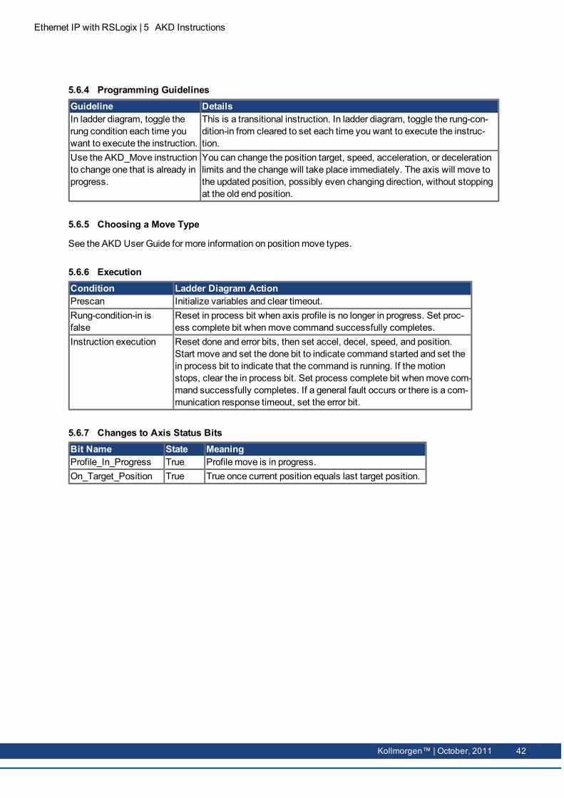
5.6.4 Programming GuidelinesGuideline DetailsIn ladder diagram, toggle therung condition each time youwant to execute the instruction.
This is a transitional instruction. In ladder diagram, toggle the rung-con-dition-in from cleared to set each time you want to execute the instruc-tion.
Use the AKD_Move instructionto change one that is already inprogress.
You can change the position target, speed, acceleration, or decelerationlimits and the change will take place immediately. The axis will move tothe updated position, possibly even changing direction, without stoppingat the old end position.
5.6.5 Choosing a Move Type
See the AKD User Guide for more information on positionmove types.
5.6.6 ExecutionCondition Ladder Diagram ActionPrescan Initialize variables and clear timeout.Rung-condition-in isfalse
Reset in process bit when axis profile is no longer in progress. Set proc-ess complete bit whenmove command successfully completes.
Instruction execution Reset done and error bits, then set accel, decel, speed, and position.Start move and set the done bit to indicate command started and set thein process bit to indicate that the command is running. If themotionstops, clear the in process bit. Set process complete bit whenmove com-mand successfully completes. If a general fault occurs or there is a com-munication response timeout, set the error bit.
5.6.7 Changes to Axis Status BitsBit Name State MeaningProfile_In_Progress True Profile move is in progress.On_Target_Position True True once current position equals last target position.
Kollmorgen™ | October, 2011 42

Ethernet IP with RSLogix | 5 AKD Instructions
5.7 Motion Axis Set Home Mode (AKD_Set_Home_Mode)
5.7.1 Description
Use themotion axis set homemode (AKD_Set_Home_Mode) instruction to set the homingmode used bythe drive when the AKD_Home command is called.
The AKD_Set_Home_Mode instruction executionmay takemultiple scans toexecute because it requires transmission of amessage to themotionmodule. TheDone (.DN) bit is not set immediately, but only after the homemode is set.
This is a transitional instruction:
l In ladder diagram, toggle the rung-condition-in from cleared to set each time the instructionshould execute.
5.7.2 OperandsOperand Type Format DescriptionAKD_Set_Home_Mode
AKD_SET_HOME_MODE
Tag Control tag for this instruction.
Axis AKD_AXIS Tag The name of the axis to modify.Mode SINT Immediate For Mode Enter:
Current Position 0Limit Input 1Limit/Zero Angle 2Limit/Index 3Home Input 4Home/Zero Angle 5Home/Index 6Zero Angle 7Position Error 8Position Error/Zero Angle 9Position Error/Index 10Index 11HomeOR Position Error 12
43 Kollmorgen™ | October, 2011

Ethernet IP with RSLogix | 5 AKD Instructions
5.7.3 AKD_SET_HOME_MODE StructureMnemonic Data
TypeDescription
.EnableIn BOOL The enable input bit indicates that the instruction is enabled. It remains setuntil the instruction completes and the rung-condition-in goes false.
.EnableOut BOOL The enable output bit is the output of the enable input bit.
.DN (Done) BOOL The done bit indicates when themode is successfully set.
.ER (Error) BOOL The error bit indicates if the instruction detects an error.
5.7.4 Homing Modes
See the AKD UserManual for a full description of each homingmode. This value corresponds to the driveparameter HOME.MODE.
5.7.5 ExecutionCondition Ladder Diagram ActionPrescan Initialize variables and clear timeout.Rung-condition-in isfalse
Initialize variables and clear timeout.
Instruction execution Reset the done and error bits and set homingmode when instruction isenabled. Set done bit when axis homingmode is set. If a general faultoccurs or there is a communication response timeout, set the error bit.
5.7.6 Changes to Axis Status BitBit Name State Meaning(none)
Kollmorgen™ | October, 2011 44

Ethernet IP with RSLogix | 5 AKD Instructions
5.8 Motion Axis Set Acceleration (AKD_Set_Accel)
5.8.1 Description
Use themotion axis set acceleration (AKD_Set_Accel) instruction to set the axis acceleration parameterused with axis moves.
The AKD_Set_Accel instruction executionmay takemultiple scans to executebecause it requires transmission of amessage to themotionmodule. The Done(.DN) bit is not set immediately, but only after the acceleration is set.
This is a transitional instruction:
l In ladder diagram, toggle the rung-condition-in from cleared to set each time the instructionshould execute.
5.8.2 OperandsOperand Type Format DescriptionAKD_Set_Accel
AKD_SET_ACCEL
Tag Control tag for this instruction.
Axis AKD_AXIS Tag The name of the axis to modify.Accel DINT Immediate Acceleration parameter for axis moves.
5.8.3 AKD_SET_ACCEL StructureMnemonic Data
TypeDescription
.EnableIn BOOL The enable input bit indicates that the instruction is enabled. It remains setuntil the instruction completes and the rung-condition-in goes false.
.EnableOut BOOL The enable output bit is the output of the enable input bit.
.DN (Done) BOOL The done bit indicates when the acceleration is successfully set.
.ER (Error) BOOL The error bit indicates if the instruction detects an error.
5.8.4 ExecutionCondition Ladder Diagram ActionPrescan Initialize variables and clear timeout.Rung-condition-in isfalse
Initialize variables and clear timeout.
Instruction execution Reset done and error bits and send acceleration commandwhen instruc-tion is enabled. Set done bit when axis command response received. If ageneral fault occurs or there is a communication response timeout, setthe error bit.
45 Kollmorgen™ | October, 2011

Ethernet IP with RSLogix | 5 AKD Instructions
5.8.5 Changes to Axis Status BitsBit Name State Meaning(none)
Kollmorgen™ | October, 2011 46

Ethernet IP with RSLogix | 5 AKD Instructions
5.9 Motion Axis Set Deceleration (AKD_Set_Decel)
5.9.1 Description
Use themotion axis set deceleration (AKD_Set_Decel) instruction to set the axis deceleration parameterused with axis moves.
The AKD_Set_Decel instruction executionmay takemultiple scans to executebecause it requires transmission of amessage to themotionmodule. The Done(.DN) bit is not set immediately, but only after the deceleration is set.
This is a transitional instruction:
l In ladder diagram, toggle the rung-condition-in from cleared to set each time the instruction shouldexecute.
5.9.2 OperandsOperand Type Format DescriptionAKD_Set_Decel
AKD_SET_DECEL
Tag Control tag for this instruction.
Axis AKD_AXIS Tag The name of the axis to modify.Decel DINT Immediate Deceleration parameter for axis moves.
5.9.3 AKD_SET_DECEL StructureMnemonic Data
TypeDescription
.EnableIn BOOL The enable input bit indicates that the instruction is enabled. It remains setuntil the instruction completes and the rung-condition-in goes false.
.EnableOut BOOL The enable output bit is the output of the enable input bit.
.DN (Done) BOOL The done bit indicates when the deceleration is successfully set.
.ER (Error) BOOL The error bit indicates if the instruction detects an error.
5.9.4 ExecutionCondition Ladder Diagram ActionPrescan Initialize variables and clear timeout.Rung-condition-in isfalse
Initialize variables and clear timeout.
Instruction execution Reset done and error bits and send deceleration commandwhen instruc-tion is enabled. Set done bit when axis command response received. If ageneral fault occurs or there is a communication response timeout, setthe error bit.
47 Kollmorgen™ | October, 2011

Ethernet IP with RSLogix | 5 AKD Instructions
5.9.5 Changes to Axis BitsBit Name State Meaning(none)
Kollmorgen™ | October, 2011 48

Ethernet IP with RSLogix | 5 AKD Instructions
5.10 Motion Axis Set Mode (AKD_Set_Mode)
5.10.1 Description
Use themotion axis set mode (AKD_Set_Mode) instruction to set the operationmode for the axis’ servoloop control.
The AKD_Set_Mode instruction executionmay takemultiple scans to executebecause it requires transmission of amessage to themotionmodule. The Done(.DN) bit is not set immediately, but only after themode is set.
This is a transitional instruction:
l In ladder diagram, toggle the rung-condition-in from cleared to set each time the instruction shouldexecute.
5.10.2 OperandsOperand Type Format DescriptionAKD_Set_Mode
AKD_SET_MODE
Tag Control tag for this instruction.
Axis AKD_AXIS Tag The name of the axis to modify.Move Type SINT Immediate For Mode Enter:
Position 0Velocity 1Torque 2
5.10.3 AKD_SET_MODE StructureMnemonic Data
TypeDescription
.EnableIn BOOL The enable input bit indicates that the instruction is enabled. It remains setuntil the instruction completes and the rung-condition-in goes false.
.EnableOut BOOL The enable output bit is the output of the enable input bit.
.DN (Done) BOOL The done bit indicates when themode is successfully set.
.ER (Error) BOOL The error bit indicates if the instruction detects an error.
5.10.4 Operation ModesMode DescriptionPosition (0) Axis will operate tomatch current position to target position.Velocity (1) Axis will operate tomatch current velocity to target velocity.Torque (2) Axis will operate tomatch current torque to target torque.
49 Kollmorgen™ | October, 2011

Ethernet IP with RSLogix | 5 AKD Instructions
5.10.5 ExecutionCondition Ladder Diagram ActionPrescan Initialize variables and clear timeout.Rung-condition-in isfalse
Initialize variables and clear timeout.
Instruction execution Reset done and error bits and sendmode commandwhen instruction isenabled. Set done bit when axis command response received. If a gen-eral fault occurs or there is a communication response timeout, set theerror bit.
5.10.6 Changes to Axis Status BitsBit Name State Meaning(none)
Kollmorgen™ | October, 2011 50

Ethernet IP with RSLogix | 5 AKD Instructions
5.11 Motion Axis Set Position (AKD_Set_Position)
5.11.1 Description
Use themotion axis set position (AKD_Set_Position) instruction to set an axis’ position target for theservo position control mode loop.
The AKD_Set_Position instruction initiates axis motion the same as the AKD_Move instruction. It is recommended to use AKD_Set_Position instruction only forupdating the target position of amove already in progress or for repeating the pre-vious move with a new target position. Use the AKD_Move for all other positionmotion.
To successfully execute an AKD_Set_Position instruction, the drivemust be enabled, homed, and in posi-tionmode.
The AKD_Set_Position instruction executionmay takemultiple scans to executebecause it requires transmission of amessage to themotionmodule. The Done(.DN) bit is not set immediately, but only after the position is set.
This is a transitional instruction:
l In ladder diagram, toggle the rung-condition-in from cleared to set each time the instruction shouldexecute.
5.11.2 OperandsOperand Type Format DescriptionAKD_Set_Position
AKD_SET_POSITION
Tag Control tag for this instruction.
Axis AKD_AXIS Tag The name of the axis to modify.Incremental BOOL Immediate For this position value Enter:
Absolute 0Incremental 1
Position DINT Immediate Position value for axis position control loop.
5.11.3 AKD_SET_POSITION StructureMnemonic Data
TypeDescription
.EnableIn BOOL The enable input bit indicates that the instruction is enabled. It remains setuntil the instruction completes and the rung-condition-in goes false.
.EnableOut BOOL The enable output bit is the output of the enable input bit.
.DN (Done) BOOL The done bit indicates when the position is successfully set.
.ER (Error) BOOL The error bit indicates if the instruction detects an error.
51 Kollmorgen™ | October, 2011

Ethernet IP with RSLogix | 5 AKD Instructions
5.11.4 ExecutionCondition Ladder Diagram ActionPrescan Initialize variables and clear timeout.Rung-condition-in isfalse
Initialize variables and clear timeout.
Instruction execution Reset done and error bits and send position commandwhen instructionis enabled. Set done bit when axis command response received. If a gen-eral fault occurs or there is a communication response timeout, set theerror bit.
5.11.5 Changes to Axis Status BitsBit Name State MeaningProfile_In_Progress True Profile move is in progress.On_Target_Position True True once current position equals last target position.
Kollmorgen™ | October, 2011 52

Ethernet IP with RSLogix | 5 AKD Instructions
5.12 Motion Axis Set Velocity (AKD_Set_Velocity)
5.12.1 Description
Use themotion axis set velocity (AKD_Set_Velocity) instruction to set an axis’ velocity setpoint for theservo control loop.
The AKD_Set_Velocity instruction initiates axis motion the same as the AKD_Joginstruction, when in velocity mode. It is recommended to use AKD_Set_Velocityinstruction only for updating the target speed of a jog already in progress and theAKD_Jog for all other constant speedmotion.
To successfully execute an AKD_Set_Velocity instruction, the drivemust be enabled, homed, and invelocity mode.
The AKD_Set_Velocity instruction executionmay takemultiple scans to executebecause it requires transmission of amessage to themotionmodule. The Done(.DN) bit is not set immediately, but only after the velocity is set.
This is a transitional instruction:
l In ladder diagram, toggle the rung-condition-in from cleared to set each time the instruction shouldexecute.
5.12.2 OperandsOperand Type Format DescriptionAKD_Set_Velocity
AKD_SET_VELOCITY
Tag Control tag for this instruction.
Axis AKD_AXIS Tag The name of the axis to modify.Velocity DINT Immediate Set velocity for axis control loop.
5.12.3 AKD_SET_VELOCITY StructureMnemonic Data
TypeDescription
.EnableIn BOOL The enable input bit indicates that the instruction is enabled. It remains setuntil the instruction completes and the rung-condition-in goes false.
.EnableOut BOOL The enable output bit is the output of the enable input bit.
.DN (Done) BOOL The done bit indicates when the velocity is successfully set.
.ER (Error) BOOL The error bit indicates if the instruction detects an error.
53 Kollmorgen™ | October, 2011

Ethernet IP with RSLogix | 5 AKD Instructions
5.12.4 ExecutionCondition Ladder Diagram ActionPrescan Initialize variables and clear timeout.Rung-condition-in isfalse
Initialize variables and clear timeout.
Instruction execution Reset done and error bits and send velocity commandwhen instructionis enabled. Set done bit when axis command response received. If a gen-eral fault occurs or there is a communication response timeout, set theerror bit.
5.12.5 Changes to Axis Status BitsBit Name State MeaningProfile_In_Progress True Profile move is in progress.On_Target_Position True True once current position equals last target position.
Kollmorgen™ | October, 2011 54

Ethernet IP with RSLogix | 5 AKD Instructions
5.13 Motion Axis Shutdown (AKD_Shutdown)
5.13.1 Description
Themotion axis shutdown (AKD_Shutdown) instruction executes a controlled stop, then disables theservo loop, disables drive output, and places the axis into the Shutdown state. This instruction is alsoreferred to as a hard stop. The shutdown state disables the drive output and deactivates the servo loop.
Another action initiated by the AKD_Shutdown instruction is the clearing of all motion processes in prog-ress and the clearing of all themotion status bits. Associated with this action, the command also clears allmotion instruction IP bits that are currently set for the targeted axis.
Another characteristic of the Shutdown state is that any instruction that initiates axis motion is blockedfrom execution. Attempts to do so result in an execution error. By executing the ShutdownReset instruc-tion or disabling and re-enabling the drivemotion can be successfully initiated again.
The axis will remain in the shutdown state until a Motion Axis ShutdownReset (AKD_Shutdown_Reset)instruction executes or the drive is disabled and re-enabled. Corresponds to theMASD instruction in Rock-well drives.
The AKD_Shutdown instruction executionmay takemultiple scans to executebecause it requires transmission of amessage to themotionmodule. The Done(.DN) bit is not set immediately, but only after the shutdown is set.
This is a transitional instruction:
l In ladder diagram, toggle the rung-condition-in from cleared to set each time the instruction shouldexecute.
5.13.2 OperandsOperand Type Format DescriptionAKD_Shut-down
AKD_SHUTDOWN Tag Control tag for this instruction.
Axis AKD_AXIS Tag The name of the axis to shut down.
5.13.3 AKD_SHUTDOWN StructureMnemonic Data
TypeDescription
.EnableIn BOOL The enable input bit indicates that the instruction is enabled. It remains setuntil the instruction completes and the rung-condition-in goes false.
.EnableOut BOOL The enable output bit is the output of the enable input bit.
.DN (Done) BOOL The done bit indicates when the axis is successfully shutdown.
.ER (Error) BOOL The error bit indicates if the instruction detects an error.
55 Kollmorgen™ | October, 2011

Ethernet IP with RSLogix | 5 AKD Instructions
5.13.4 ExecutionCondition Ladder Diagram Actionrung-condition-in is false Clears hard stop command.instruction execution Send hard stop commandwhen instruction is enabled. Set done bit when
profile in progress is cleared. If a general fault occurs set the error bit.
5.13.5 Changes to Axis Status BitsBit Name State MeaningProfile_In_Progress True Nomove is in progressEnable True Axis is in Disabled state with the servo loop inactive.
Kollmorgen™ | October, 2011 56

Ethernet IP with RSLogix | 5 AKD Instructions
5.14 Motion Axis Shutdown Reset (AKD_Shutdown_Reset)
5.14.1 Description
Use themotion axis shutdown reset (AKD_Shutdown_Reset) instruction to transition an axis from theShutdown state to the Disabled ready state. All faults associated with the specified axis are automaticallycleared. Corresponds to theMASR instruction in Rockwell drives.
The AKD_Shutdown_Reset instruction executionmay takemultiple scans toexecute because it requires transmission of amessage to themotionmodule andtime for the drive to execute the command. The Done (.DN) bit is not set imme-diately, but only after the drive is reset.
This is a transitional instruction:
l In ladder diagram, toggle the rung-condition-in from cleared to set each time the instruction shouldexecute.
5.14.2 OperandsOperand Type Format DescriptionAKD_Shut-down_Reset
AKD_SHUT-DOWN_RESET
Tag Control tag for this instruction.
Axis AKD_AXIS Tag The name of the axis to reset.
5.14.3 AKD_SHUTDOWN_RESET StructureMnemonic Data
TypeDescription
.EnableIn BOOL The enable input bit indicates that the instruction is enabled. It remains setuntil the instruction completes and the rung-condition-in goes false.
.EnableOut BOOL The enable output bit is the output of the enable input bit.
.DN (Done) BOOL The done bit indicates when the axis is successfully reset.
.ER (Error) BOOL The error bit indicates if the instruction detects an error.
5.14.4 ExecutionCondition Ladder Diagram ActionPrescan Initialize variables and clear timeout.Rung-condition-in isfalse
Initialize variables and clear timeout.
Instruction execution Reset done and error bits, disable axis, and reset faults. Set done bitwhen all axis command responses received. If a general fault occurs orthere is a communication response timeout, set the error bit.
57 Kollmorgen™ | October, 2011

Ethernet IP with RSLogix | 5 AKD Instructions
5.14.5 Changes to Axis Status BitsBit Name State MeaningGeneral_Fault False No general fault is present.Enable False Axis is disabled.FE_Fault False No following error fault is present.Block_Fault False No block execution fault is present.
Kollmorgen™ | October, 2011 58
Ethernet IP with RSLogix | 5 AKD Instructions
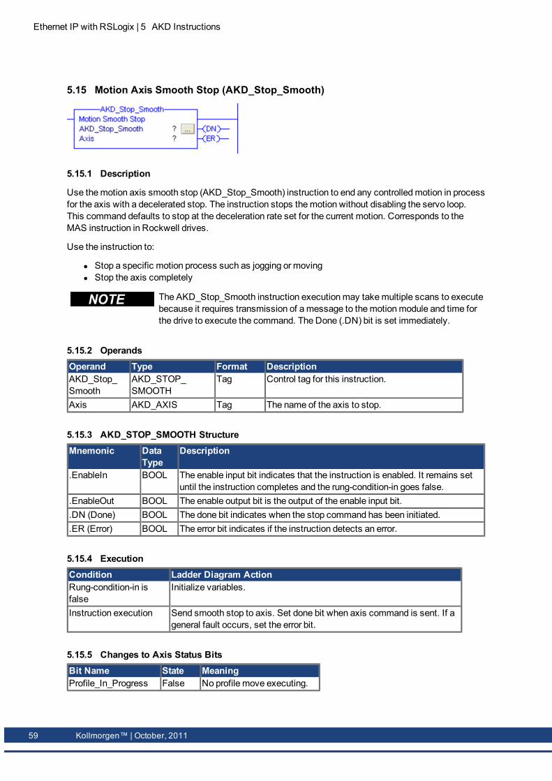
5.15 Motion Axis Smooth Stop (AKD_Stop_Smooth)
5.15.1 Description
Use themotion axis smooth stop (AKD_Stop_Smooth) instruction to end any controlledmotion in processfor the axis with a decelerated stop. The instruction stops themotion without disabling the servo loop.This command defaults to stop at the deceleration rate set for the current motion. Corresponds to theMAS instruction in Rockwell drives.
Use the instruction to:
l Stop a specific motion process such as jogging or movingl Stop the axis completely
The AKD_Stop_Smooth instruction executionmay takemultiple scans to executebecause it requires transmission of amessage to themotionmodule and time forthe drive to execute the command. The Done (.DN) bit is set immediately.
5.15.2 OperandsOperand Type Format DescriptionAKD_Stop_Smooth
AKD_STOP_SMOOTH
Tag Control tag for this instruction.
Axis AKD_AXIS Tag The name of the axis to stop.
5.15.3 AKD_STOP_SMOOTH StructureMnemonic Data
TypeDescription
.EnableIn BOOL The enable input bit indicates that the instruction is enabled. It remains setuntil the instruction completes and the rung-condition-in goes false.
.EnableOut BOOL The enable output bit is the output of the enable input bit.
.DN (Done) BOOL The done bit indicates when the stop command has been initiated.
.ER (Error) BOOL The error bit indicates if the instruction detects an error.
5.15.4 ExecutionCondition Ladder Diagram ActionRung-condition-in isfalse
Initialize variables.
Instruction execution Send smooth stop to axis. Set done bit when axis command is sent. If ageneral fault occurs, set the error bit.
5.15.5 Changes to Axis Status BitsBit Name State MeaningProfile_In_Progress False No profile move executing.
59 Kollmorgen™ | October, 2011

Ethernet IP with RSLogix | 5 AKD Instructions
5.16 Motion Axis Get Position Controller Attribute (AKD_Get_Attribute)
5.16.1 Description
Use themotion axis get attribute (AKD_Get_Attribute) instruction to query a Position Controller attributefrom an axis. This instruction provides quick access to a special set of drive parameters which canalways be accessed in one communication cycle. The output value will be updated with live values eachcycle as long as this instruction is enabled.
This instructionmust not be enabled at the same time as the AKD_Get_Parameterinstruction.
See Appendix A: Position Controller Object Attributes for a list of available attributes and numbering.
5.16.2 OperandsOperand Type Format DescriptionAKD_Get_Attribute
AKD_GET_ATTRIBUTE
Tag Control tag for this instruction.
Axis AKD_AXIS Tag The name of the axis to query.Attribute_Number
INT Immediate (See Appendix A: Position Controller Object Attrib-utes)
Attribute_Value
DINT Tag Output tag to which the value of the attribute ispassed.
5.16.3 AKD_GET_ATTRIBUTE StructureMnemonic Data
TypeDescription
.EnableIn BOOL The enable input bit indicates that the instruction is enabled. It remains setuntil the instruction completes and the rung-condition-in goes false.
.EnableOut BOOL The enable output bit is the output of the enable input bit.
.DN (Done) BOOL The done bit indicates when the get attribute command has been completed.
.ER (Error) BOOL The error bit indicates if the instruction detects an error.
5.16.4 ExecutionCondition Ladder Diagram ActionPre-scan Initialize variables and clear timeout.Rung-condition-in isfalse
Initialize variables and clear timeout.
Instruction execution Send command to axis to request value. Set done bit and copy responseto attribute value output when axis response is received. If a general faultor timeout occurs, set the error bit.
Kollmorgen™ | October, 2011 60

Ethernet IP with RSLogix | 5 AKD Instructions
5.16.5 Changes to Axis Status BitsBit Name State Meaning(none)
61 Kollmorgen™ | October, 2011

Ethernet IP with RSLogix | 5 AKD Instructions
5.17 Motion Axis Set Position Controller Attribute (AKD_Set_Attribute)
5.17.1 Description
Use themotion axis set attribute (AKD_Set_Attribute) instruction to set a Position Controller attribute foran axis. This instruction provides quick access to a special set of drive parameters which can always beset in one communication cycle. See Appendix A: Position Controller Object Attributes for a list of avail-able attributes and numbering.
5.17.2 OperandsOperand Type Format DescriptionAKD_Set_Attribute
AKD_SET_ATTRIBUTE
Tag Control tag for this instruction.
Axis AKD_AXIS Tag The name of the axis to modify.Attribute_Number
INT Immediate (See Appendix A: Position Controller Object Attrib-utes)
Attribute_Value
DINT Immediate Value to which the specified attribute will be set.
5.17.3 AKD_SET_ATTRIBUTE StructureMnemonic Data
TypeDescription
.EnableIn BOOL The enable input bit indicates that the instruction is enabled. It remains setuntil the instruction completes and the rung-condition-in goes false.
.EnableOut BOOL The enable output bit is the output of the enable input bit.
.DN (Done) BOOL The done bit indicates when the set attribute command has been completed.
.ER (Error) BOOL The error bit indicates if the instruction detects an error.
5.17.4 ExecutionCondition Ladder Diagram ActionPre-scan Initialize variables and clear timeout.Rung-condition-in isfalse
Initialize variables and clear timeout.
Instruction execution Send command to axis to set value. Set done bit when axis response isreceived. If a general fault or timeout occurs, set the error bit.
5.17.5 Changes to Axis Status BitsBit Name State Meaning(none)
Kollmorgen™ | October, 2011 62

Ethernet IP with RSLogix | 5 AKD Instructions
5.18 Motion Axis Set Parameter (AKD_Set_Parameter)
5.18.1 Description
Use themotion axis set parameter (AKD_Set_Parameter) instruction tomodify a drive parameter orexecute a drive command on an axis. The time required to execute the command is highly dependent onthe particular parameter. See Appendix B: AKD Parameters for a list of available parameters and num-bering.
5.18.2 OperandsOperand Type Format DescriptionAKD_Set_Parameter
AKD_SET_PARAMETER
Tag Control tag for this instruction.
Axis AKD_AXIS Tag The name of the axis to modify.Parameter_Number
INT Immediate (See Appendix B: AKD Parameters)
Parameter_Value
DINT Immediate Value to which the specified parameter will be set.
5.18.3 AKD_SET_PARAMETER STRUCTUREMnemonic Data
TypeDescription
.EnableIn BOOL The enable input bit indicates that the instruction is enabled. It remains setuntil the instruction completes and the rung-condition-in goes false.
.EnableOut BOOL The enable output bit is the output of the enable input bit.
.DN (Done) BOOL The done bit indicates when the set parameter command has been com-pleted.
.ER (Error) BOOL The error bit indicates if the instruction detects an error.
5.18.4 ExecutionCondition Ladder Diagram ActionPre-scan Initialize variables and clear timeout.Rung-condition-in isfalse
Initialize variables and clear timeout.
Instruction execution Send command to axis to set value. Set done bit when axis response isreceived. If a general fault or timeout occurs, set the error bit.
5.18.5 Changes to Axis Status BitsBit Name State Meaning(none)
63 Kollmorgen™ | October, 2011

Ethernet IP with RSLogix | 5 AKD Instructions
5.19 Motion Axis Set Units (AKD_Set_Units)
5.19.1 Description
Use themotion axis set units (AKD_Set_Units) instruction to set the current unit system used on an axis.
At themoment, only mode 0 (EIP.POSUNIT=65536 and EIP.PROFUNIT=65536) is available. Thesescaling values can also bemodified directly through EtherNet/IP orWorkbench. See the AKD Eth-erNet/IP User Manual for more information about unit scaling.
5.19.2 OperandsOperand Type Format DescriptionAKD_Set_Units
AKD_SET_UNITS
Tag Control tag for this instruction.
Axis AKD_AXIS Tag The name of the axis to modify.Units SINT Immediate For units Enter:
Counts 0
5.19.3 AKD_SET_UNITS StructureMnemonic Data
TypeDescription
.EnableIn BOOL The enable input bit indicates that the instruction is enabled. It remains setuntil the instruction completes and the rung-condition-in goes false.
.EnableOut BOOL The enable output bit is the output of the enable input bit.
.DN (Done) BOOL The done bit indicates when the set units command has been completed.
.ER (Error) BOOL The error bit indicates if the instruction detects an error.
5.19.4 ExecutionCondition Ladder Diagram ActionPre-scan Initialize variables and clear timeout.Rung-condition-in isfalse
Initialize variables and clear timeout.
Instruction execution Send command to axis to set units and if necessary update settings. Setdone bit when axis response is received. If a general fault or timeoutoccurs, set the error bit.
5.19.5 Changes to Axis Status BitsBit Name State Meaning(none)
Kollmorgen™ | October, 2011 64

Ethernet IP with RSLogix | 6 Troubleshooting
6 TroubleshootingCommunication Timeout
The instructions share a common “timeout” value in the controller tag AKD_Axis.CommandTimeout. Thisvalue is used to count downwhen a command is sent using an explicit message, to ensure a response isreceived as expected. In some project configurations, this timeout may need to be increased, such as ifthe rung for an Add-On instruction is only scanned once per second. In this case, increase the value ofCommandTimeout.
65 Kollmorgen™ | October, 2011

Ethernet IP with RSLogix | 7 Appendix A: Supported EtherNet/IP Objects and Attributes
7 Appendix A: Supported EtherNet/IP Objects andAttributes
7.1 Position Controller Class 0x25AttributeID
Name AccessRule
Type Description
1 Number of Attributes Get USINT Returns the total number of attributes supported bythis object in this device.
2 Attribute List Get Array ofUSINT
Returns an array with a list of the attributes sup-ported by this object in this device.
3 Mode Get/Set USINT Operatingmode. 0 = Positionmode(default), 1 =Velocity mode, 2 = Torquemode.
4 Position Units Get/Set DINT Position Units ratio value is the number of actualposition feedback counts equal to one position unit(default 1).
5 Profile Units Get/Set DINT Profile Units ratio value is the number of actualposition feedback counts per second or second2equal to one velocity, acceleration or decelerationunit (default 1).
6 Target Position Get/Set DINT Returns 1 for the AKD (only one axis support).7 Target Velocity Get/Set DINT General fault flag.8 Acceleration Get/Set DINT Not used yet.9 Deceleration Get/Set DINT Not used yet.10 Incremental Position
FlagGet/Set BOOL Incremental Position Flag 0 := absolute, 1:= incre-
mental.11 Load Data/Profile
HandshakeGet/Set BOOL Used to Load CommandData, Start a Profile
Move, and indicate that a Profile Move is in prog-ress.
17 Enable Get/Set BOOL Enable Output (same as DRV.EN).25 Torque Get/Set DINT Output torque.58 Load Data Complete Get/Set BOOL Indicates that valid data for a valid I/O command
message type has been loaded into the positioncontroller device.
100 HomeMode Get/Set INT See homemode section of the AKD UserManual101 HomeMove Set BOOL Initiate a homemove.
Kollmorgen™ | October, 2011 66

Ethernet IP with RSLogix | 8 Appendix B Parameter Listing
8 Appendix B Parameter ListingThe parameters in this list correspond to drive parameters available inWorkbench and aredescribed in theWorkbench help documentation.Position values are scaled according to the Position Units attribute 4 of the PositionController Object.Velocity and Acceleration values are scaled according to the Profile Units attribute 5 of the Posi-tion Controller Object.Other floating point values aremultiplied by 1000, such that a value displayed inWorkbench as1.001 will be transmitted through EtherNet/IP as 1001.
Instance Parameter Data Size Data Type1 AIN.CUTOFF 4 Byte Float2 AIN.DEADBAND 2Byte Float3 AIN.ISCALE 4 Byte Float4 AIN.OFFSET 2 Byte Signed Float5 AIN.PSCALE 8 Byte Position7 AIN.VALUE 2 Byte Float8 AIN.VSCALE 4 Byte Velocity9 AIN.ZERO Command None10 AOUT.ISCALE 4 Byte Float11 AOUT.MODE 2 Byte Integer12 AOUT.OFFSET 2 Byte Signed Float13 AOUT.PSCALE 8 Byte Position15 AOUT.VALUE 8 Byte Signed Float17 AOUT.VALUEU 8 Byte Signed Float19 AOUT.VSCALE 4 Byte Velocity20 BODE.EXCITEGAP 1 Byte Integer21 BODE.FREQ 4Byte Float22 BODE.IAMP 2 Byte Signed Float23 BODE.INJECTPOINT 1 Byte Integer24 BODE.MODE 1 Byte Integer25 BODE.MODETIMER 4 Byte Integer26 BODE.PRBDEPTH 1 Byte Integer27 BODE.VAMP 8 Byte Signed Velocity28 CAP0.EDGE 1 Byte Integer29 CAP0.EN 1 Byte Integer30 CAP0.EVENT 1 Byte Integer31 CAP0.FILTER 1 Byte Integer32 CAP0.MODE 1 Byte Integer33 CAP0.PLFB 8 Byte Signed Position35 CAP0.PREEDGE 1Byte Integer36 CAP0.PREFILTER 1 Byte Integer37 CAP0.PRESLECT 1 Byte Integer38 CAP0.STATE 1 Byte Integer
67 Kollmorgen™ | October, 2011

Ethernet IP with RSLogix | 8 Appendix B Parameter Listing
Instance Parameter Data Size Data Type39 CAP0.T 4 Byte Integer40 CAP0.TRIGGER 1Byte Integer41 CAP1.EDGE 1 Byte Integer42 CAP1.EN 1 Byte Integer43 CAP1.EVENT 1 Byte Integer44 CAP1.FILTER 1 Byte Integer45 CAP1.MODE 1 Byte Integer46 CAP1.PLFB 8 Byte Signed Position48 CAP1.PREEDGE 1Byte Integer49 CAP1.PREFILTER 1 Byte Integer50 CAP1.PRESELECT 1 Byte Integer51 CAP1.STATE 1 Byte Integer52 CAP1.T 4 Byte Integer53 CAP1.TRIGGER 1Byte Integer54 CS.DEC 8 byte Acceleration56 CS.STATE 1 Byte Integer57 CS.TO 4 Byte Integer58 CS.VTHRESH 8 Byte Velocity59 DIN.ROTARY 1 Byte Integer60 DIN.STATES 1 Byte Array61 DIN1.INV 1 Byte Integer62 DIN1.MODE 2 Byte Integer63 DIN1.PARAM 8Byte Signed Varies65 DIN1.STATE 1 Byte Integer66 DIN2.INV 1 Byte Integer67 DIN2.MODE 2 Byte Integer68 DIN2.PARAM 8Byte Signed Varies70 DIN2.STATE 1 Byte Integer71 DIN3.INV 1 Byte Integer72 DIN3.MODE 2 Byte Integer73 DIN3.PARAM 8Byte Signed Varies75 DIN3.STATE 1 Byte Integer76 DIN4.INV 1 Byte Integer77 DIN4.MODE 2 Byte Integer78 DIN4.PARAM 8Byte Signed Varies80 DIN4.STATE 1 Byte Integer81 DIN5.INV 1 Byte Integer82 DIN5.MODE 2 Byte Integer83 DIN5.PARAM 8Byte Signed Varies85 DIN5.STATE 1 Byte Integer86 DIN6.INV 1 Byte Integer87 DIN6.MODE 2 Byte Integer88 DIN6.PARAM 8Byte Signed Varies90 DIN6.STATE 1 Byte Integer
Kollmorgen™ | October, 2011 68

Ethernet IP with RSLogix | 8 Appendix B Parameter Listing
Instance Parameter Data Size Data Type91 DIN7.INV 1 Byte Integer92 DIN7.MODE 2 Byte Integer93 DIN7.PARAM 8Byte Signed Varies95 DIN7.STATE 1 Byte Integer96 DOUT.CTRL 1 Byte Integer97 DOUT.RELAYMODE 1Byte Integer98 DOUT.STATES 1 Byte Array99 DOUT1.MODE 1 Byte Integer100 DOUT1.PARAM 8Byte Signed Float102 DOUT1.STATE 1 Byte Integer103 DOUT1.STATEU 1 Byte Integer104 DOUT2.MODE 1 Byte Integer105 DOUT2.PARAM 8Byte Signed Float107 DOUT2.STATE 1 Byte Integer108 DOUT2.STATEU 1 Byte Integer109 DRV.ACC 8 Byte Acceleration111 DRV.ACTIVE 1 Byte Integer112 DRV.CLRFAULTHIST Command None113 DRV.CLRFAULTS Command None114 DRV.CMDSOURCE 1 Byte Integer115 DRV.DBILIMIT 2 Byte Float116 DRV.DEC 8 Byte Acceleration118 DRV.DIR 1 Byte Integer119 DRV.DI Command None120 DRV.DISMODE 1 Byte Integer121 DRV.DISSOURCES 2 Byte Integer122 DRV.DISTO 4 Byte Integer123 DRV.EMUEDIR 1 Byte Integer124 DRV.EMUEMODE 2Byte Integer125 DRV.EMUEMTURN 4Byte Integer126 DRV.EMUERES 4 Byte Integer127 DRV.EMUEZOFFSET 2 Byte Integer128 DRV.EN Command None129 DRV.ENDEFAULT 1 Byte Integer130 DRV.HANDWHEEL 4 Byte Integer131 DRV.HWENMODE 1Byte Integer132 DRV.ICONT 2 Byte Signed Float133 DRV.IPEAK 2 Byte Signed Float134 DRV.IZERO 2Byte Float135 DRV.MOTIONSTAT 4 Byte Integer136 DRV.OPMODE 1Byte Integer137 DRV.RSTVAR Command None138 DRV.STOP Command None139 DRV.TYPE 1 Byte Integer
69 Kollmorgen™ | October, 2011

Ethernet IP with RSLogix | 8 Appendix B Parameter Listing
Instance Parameter Data Size Data Type140 DRV.ZERO 1Byte Integer141 FB1.BISSBITS 1 Byte Integer142 FB1.ENCRES 4 Byte Integer143 FB1.IDENTIFIED 1 Byte Integer144 FB1.INITSIGNED 1 Byte Signed Integer145 FB1.MECHPOS 4 Byte Integer146 FB1.OFFSET 8 Byte Signed Position148 FB1.ORIGIN 8 Byte Position150 FB1.PFIND 1 Byte Integer151 FB1.PFINDCMDU 2Byte Float152 FB1.POLES 2 Byte Integer153 FB1.PSCALE 1 Byte Integer154 FB1.RESKTR 2 Byte Float155 FB1.RESREFPHASE 4 Byte Signed Float156 FB1.SELECT 1 Byte Signed Integer157 FB1.TRACKINGCAL 1 Byte Integer158 FBUS.PARAM01 4 Byte Integer159 FBUS.PARAM02 4 Byte Integer160 FBUS.PARAM03 4 Byte Integer161 FBUS.PARAM04 4 Byte Integer162 FBUS.PARAM05 4 Byte Integer163 FBUS.PARAM06 4 Byte Integer164 FBUS.PARAM07 4 Byte Integer178 FBUS.PLLTHRESH 2 Byte Integer179 FBUS.SAMPLEPERIOD 1 Byte Integer180 FBUS.SYNCACT 4 Byte Integer181 FBUS.SYNCDIST 4 Byte Integer182 FBUS.SYNCWND 4Byte Integer183 FBUS.TYPE 1 Byte Integer184 GEAR.ACCMAX 8 Byte Acceleration186 GEAR.DECMAX 8 Byte Acceleration188 GEAR.IN 2 Byte Integer189 GEAR.MODE 2 Byte Integer190 GEAR.MOVE Command None191 GEAR.OUT 2 Byte signed Integer192 GEAR.VMAX 8 Byte Velocity193 HOME.ACC 8 Byte Acceleration195 HOME.AUTOMOVE 1 Byte Integer196 HOME.DEC 8 Byte Acceleration198 HOME.DIR 2 Byte Integer199 HOME.DIST 8 Byte Signed Position201 HOME.FEEDRATE 2 Byte Integer202 HOME.IPEAK 4 Byte Signed Float204 HOME.MODE 2 Byte Integer
Kollmorgen™ | October, 2011 70

Ethernet IP with RSLogix | 8 Appendix B Parameter Listing
Instance Parameter Data Size Data Type205 HOME.MOVE Command None206 HOME.P 8 Byte Signed Position208 HOME.PERRTHRESH 8Byte Signed Position210 HOME.SET Command None211 HOME.V 8 Byte Velocity212 HWLS.NEGSTATE 1 Byte Integer213 HWLS.POSSTATE 1 Byte Integer214 IL.BUSFF 2 Byte Signed Float215 IL.CMD 2Byte Signed Float216 IL.CMDU 2Byte Signed Float217 IL.FB 2 Byte Signed Float218 IL.FF 2 Byte Float219 IL.FOLDFTHRESH 2 Byte Float220 IL.FOLDFTHRESHU 4Byte Signed Float221 IL.FOLDWTHRESH 4Byte Signed Float222 IL.FRICTION 4 Byte Float223 IL.IFOLDS 4 Byte Float224 IL.IUFB 2 Byte Signed Float225 IL.IVFB 2 Byte Signed Float226 IL.KACCFF 4 Byte Signed Float227 IL.KBUSFF 4 Byte Float228 IL.KP 2 Byte Float229 IL.KPDRATIO 4 Byte Float230 IL.KVFF 4 Byte Signed Float231 IL.LIMITN 4 Byte Signed Float232 IL.LIMITP 4 Byte Signed Float233 IL.MFOLDD 4 Byte Float234 IL.MFOLDR 4 Byte Float235 IL.MFOLDT 4 Byte Float236 IL.MIFOLD 4 Byte Float237 IL.OFFSET 4 Byte Signed Float238 IL.VCMD 2Byte Signed Integer239 IL.VUFB 2 Byte Signed Integer240 IL.VVFB 2 Byte Signed Integer241 MOTOR.AUTOSET 1 Byte Integer242 MOTOR.BRAKE 1 Byte Integer243 MOTOR.BRAKERLS 1 Byte Integer244 MOTOR.CTF0 4 Byte Float245 MOTOR.ICONT 4 Byte Float246 MOTOR.IDDATAVALID 1 Byte Integer247 MOTOR.INTERTIA 4 Byte Float248 MOTOR.IPEAK 4 Byte Float249 MOTOR.KT 4 Byte Float250 MOTOR.LQLL 4 Byte Float
71 Kollmorgen™ | October, 2011

Ethernet IP with RSLogix | 8 Appendix B Parameter Listing
Instance Parameter Data Size Data Type251 MOTOR.PHASE 2 Byte Integer252 MOTOR.PITCH 4 Byte Float253 MOTOR.POLES 2 Byte Integer254 MOTOR.R 4 Byte Float255 MOTOR.RTYPE 1 Byte Integer256 MOTOR.TBRAKEAPP 2 Byte Integer257 MOTOR.TBRAKERLS 2 Byte Integer258 MOTOR.TEMP 4 Byte Integer259 MOTOR.TEMPFAULT 4 Byte Integer260 MOTOR.TEMPWARN 4Byte Integer261 MOTOR.TYPE 1 Byte Integer262 MOTOR.VMAX 2 Byte Integer263 MOTOR.VOLTMAX 2 Byte Integer264 MT,ACC 8 Byte Acceleration266 MT.CLEAR 2 Byte Signed Integer267 MT.CNTL 4 Byte Integer268 MT.CONTINUE Command None269 MT.DEC 8 Byte Acceleration271 MT.EMERGMT 2 Byte Signed Integer272 MT.LOAD Command None273 MT.MOVE 2 Byte Command None274 MT.MTNEXT 1 Byte Integer275 MT.NUM 1Byte Integer276 MT.P 8 Byte Signed Position278 MT.SET 1 Byte Command None279 MT.TNEXT 2 Byte Integer280 MT.TNUM 1Byte Integer281 MT.TPOSWND 8Byte Signed Position283 MT.TVELWND 8Byte Velocity284 MT.V 8 Byte Velocity285 MT.VCMD 8Byte Signed Velocity286 PL.CMD 8Byte Position288 PL.ERR 8 Byte Position290 PL.ERRMODE 1Byte Integer291 PL.ERRFTHRESH 8 Byte Position293 PL.ERRWTHRESH 8Byte Position295 PL.FB 8 Byte Signed Position297 PL.FBSOURCE 1 Byte Integer298 PL.INTINMAX 8 Byte Position300 PL.INTOUTMAX 8 Byte Position302 PL.KI 4 Byte Float303 PL.KP 4 Byte Float304 PL.MODP1 8 Byte Signed Position306 PL.MODP2 8 Byte Signed Position
Kollmorgen™ | October, 2011 72

Ethernet IP with RSLogix | 8 Appendix B Parameter Listing
Instance Parameter Data Size Data Type308 PL.MODPDIR 1 Byte Integer309 PL.MODPEN 1Byte Integer310 PLS.EN 2 Byte Integer311 PLS.MODE 2 Byte Integer312 PLS.P1 8 Byte Signed Position314 PLS.P2 8 Byte Signed Position316 PLS.P3 8 Byte Signed Position318 PLS.P4 8 Byte Signed Position320 PLS.P5 8 Byte Signed Position322 PLS.P6 8 Byte Signed Position324 PLS.P7 8 Byte Signed Position326 PLS.P8 8 Byte Signed Position328 PLS.RESET 2 Byte Integer329 PLS.STATE 2 Byte Integer330 PLS.T1 2 Byte Integer331 PLS.T2 2 Byte Integer332 PLS.T3 2 Byte Integer333 PLS.T4 2 Byte Integer334 PLS.T5 2 Byte Integer335 PLS.T6 2 Byte Integer336 PLS.T7 2 Byte Integer337 PLS.T8 2 Byte Integer338 PLS.UNITS 1 Byte Integer339 PLS.WIDTH1 8 Byte Signed Position341 PLS.WIDTH2 8 Byte Signed Position343 PLS.WIDTH3 8 Byte Signed Position345 PLS.WIDTH4 8 Byte Signed Position347 PLS.WIDTH5 8 Byte Signed Position349 PLS.WIDTH6 8 Byte Signed Position351 PLS.WIDTH7 8 Byte Signed Position353 PLS.WIDTH8 8 Byte Signed Position355 REC.ACTIVE 1 Byte Integer356 REC.DONE 1 Byte Integer357 REC.GAP 2 Byte Integer358 REC.NUMPOINTS 2 Byte Integer359 REC.OFF Command None360 REC.STOPTYPE 1 Byte Integer361 REC.TRIG Command None362 REC.TRIGPOS 1 Byte Integer363 REC.TRIGPRMLIST - String364 REC.TRIGSLOPE 1 Byte Integer365 REC.TRIGTYPE 1 Byte Integer366 REC.TRIGVAL 8 Byte Signed Varies368 REGEN.POWER 8Byte Integer
73 Kollmorgen™ | October, 2011

Ethernet IP with RSLogix | 8 Appendix B Parameter Listing
Instance Parameter Data Size Data Type370 REGEN.REXT 2 Byte Integer371 REGEN.TEXT 4 Byte Float372 REGEN.TYPE 1 Byte Signed Integer373 REGEN.WATTEXT 2 Byte Integer374 SM.I1 2 Byte Signed Float375 SM.I2 2 Byte Signed Float376 SM.MODE 2 Byte Integer377 SM.MOVE Command None378 SM.T1 2 Byte Integer379 SM.T2 2 Byte Integer380 SM.V1 8 Byte Signed Velocity381 SM.V2 8 Byte Signed Velocity382 STO.STATE 1 Byte Integer383 SWLS.EN 2 Byte Integer384 SWLS.LIMIT0 8 Byte Signed Position386 SWLS.LIMIT1 8 Byte Signed Position388 SWLS.STATE 2 Byte Integer389 UNIT.ACCLINEAR 1 Byte Integer390 UNIT.ACCROTARY 1 Byte Integer391 UNIT.PIN 4 Byte Integer392 UNIT.PLINEAR 1 Byte Integer393 UNIT.POUT 4 Byte Integer394 UNIT.PROTARY 1 Byte Integer395 UNIT.VLINEAR 1 Byte Integer396 UNIT.VROTARY 1 Byte Integer397 VBUS.CALGAIN 4 Byte Float398 VBUS.OVFTHRESH 2 Byte Integer399 VBUS.OVWTHRESH 2Byte Integer400 VBUS.RMSLIMIT 1 Byte Integer401 VBUS.UVFTHRESH 2 Byte Integer402 VBUS.UVMODE 1Byte Integer403 VBUS.UVWTHRESH 2Byte Integer404 VBUS.VALUE 4 Byte Float405 VL.ARPF1 4 Byte Float406 VL.ARPF2 4 Byte Float407 VL.ARPF3 4 Byte Float408 VL.ARPF4 4 Byte Float409 VL.ARPQ1 4 Byte Float410 VL.ARPQ2 4 Byte Float411 VL.ARPQ3 4 Byte Float412 VL.ARPQ4 4 Byte Float413 VL.ARTYPE1 1 Byte Integer414 VL.ARTYPE2 1 Byte Integer415 VL.ARTYPE3 1 Byte Integer
Kollmorgen™ | October, 2011 74

Ethernet IP with RSLogix | 8 Appendix B Parameter Listing
Instance Parameter Data Size Data Type416 VL.ARTYPE4 1 Byte Integer417 VL.ARZF1 4 Byte Float418 VL.ARZF2 4 Byte Float419 VL.ARZF3 4 Byte Float420 VL.ARZF4 4 Byte Float421 VL.ARZQ1 4 Byte Float422 VL.ARZQ2 4 Byte Float423 VL.ARZQ3 4 Byte Float424 VL.ARZQ4 4 Byte Float425 VL.BUSFF 8 Byte Signed Velocity426 VL.CMD 8Byte Signed Velocity427 VL.CMDU 8Byte Signed Velocity428 VL.ERR 8 Byte Signed Velocity429 VL.FB 8 Byte Signed Velocity430 VL.FBFILTER 8 Byte Signed Velocity431 VL.FBSOURCE 1 Byte Integer432 VL.FF 8 Byte Signed Velocity433 VL.GENMODE 2Byte Velocity434 VL.KBUSFF 4 Byte Float435 VL.KI 4 Byte Float436 VL.KO 4 Byte Float437 VL.KP 4 Byte Float438 VL.KVFF 4 Byte Float439 VL.LIMITN 8 Byte Signed Velocity440 VL.LIMITP 8 Byte Velocity441 VL.LMJR 4 Byte Float442 VL.MODEL 8 Byte Signed Velocity443 VL.OBSBW 4Byte Float444 VL.OBSMODE 4Byte Integer445 VL.THRESH 8 Byte Signed Velocity446 WS.ARM Command None447 WS.DISTMAX 8 Byte Signed Position449 WS.DISTMIN 8 Byte Signed Position451 WS.IMAX 2 Byte Signed Float452 WS.MODE 1 Byte Integer453 WS.NUMLOOPS 1 Byte Integer454 WS.STATE 1 Byte Integer455 WS.T 2 Byte Integer456 WS.TDELAY1 2 Byte Integer457 WS.TDELAY2 2 Byte Integer458 WS.TDELAY3 2 Byte Integer459 WS.VTHRESH 8 Byte Signed Velocity460 DIN1.FILTER 2 Byte Integer461 DIN2.FILTER 2 Byte Integer
75 Kollmorgen™ | October, 2011

Ethernet IP with RSLogix | 8 Appendix B Parameter Listing
Instance Parameter Data Size Data Type462 DIN3.FILTER 2 Byte Integer463 DIN4.FILTER 2 Byte Integer464 DIN5.FILTER 2 Byte Integer465 DIN6.FILTER 2 Byte Integer466 DIN7.FILTER 2 Byte Integer467 FB1.HALLSTATEU 1 Byte Integer468 FB1.HALLSTATEV 1 Byte Integer469 FB1.HALLSTATEW 1Byte Integer470 DRV.NVSAVE Command None471 MODBUS.DIO 4 Byte Integer472 MODBUS.DRV 4 Byte Integer473 MODBUS.DRVSTAT 4 Byte Integer474 MODBUS.HOME 4Byte Integer475 MODBUS.MOTOR 4Byte Integer476 MODBUS.MT 2 Byte Integer477 MODBUS.SM 4Byte Integer478 DRV.FAULT1 2 Byte Integer479 DRV.FAULT2 2 Byte Integer480 DRV.FAULT3 2 Byte Integer481 DRV.FAULT4 2 Byte Integer482 DRV.FAULT5 2 Byte Integer483 DRV.FAULT6 2 Byte Integer484 DRV.FAULT7 2 Byte Integer485 DRV.FAULT8 2 Byte Integer486 DRV.FAULT9 2 Byte Integer487 DRV.FAULT10 2 Byte Integer488 MODBUS.PIN 4 Byte Integer489 MODBUS.POUT 4 Byte Integer490 MODBUS.PSCALE 2 Byte Integer491 MODBUS.UNITLABEL - String492 MOTOR.HFPHASEREAD 2 Byte Integer493 FB2.ENCRES 4 Byte Integer494 FB2.MODE 2 Byte Integer495 FB2.SOURCE 2 Byte Integer496 MOTOR.TBRAKETO 2Byte Integer497 MODBUS.MSGLOG 1Byte Integer498 USER.INT1 4 Byte Signed Integer499 USER.INT2 4 Byte Signed Integer500 USER.INT3 4 Byte Signed Integer501 USER.INT4 4 Byte Signed Integer502 USER.INT5 4 Byte Signed Integer503 USER.INT6 4 Byte Signed Integer504 USER.INT7 4 Byte Signed Integer505 USER.INT8 4 Byte Signed Integer
Kollmorgen™ | October, 2011 76

Ethernet IP with RSLogix | 8 Appendix B Parameter Listing
Instance Parameter Data Size Data Type506 USER.INT9 4 Byte Signed Integer507 USER.INT10 4 Byte Signed Integer508 USER.INT11 4 Byte Signed Integer509 USER.INT12 4 Byte Signed Integer510 USER.INT13 4 Byte Signed Integer511 USER.INT14 4 Byte Signed Integer512 USER.INT15 4 Byte Signed Integer513 USER.INT16 4 Byte Signed Integer514 USER.INT17 4 Byte Signed Integer515 USER.INT18 4 Byte Signed Integer516 USER.INT19 4 Byte Signed Integer517 USER.INT20 4 Byte Signed Integer518 USER.INT21 4 Byte Signed Integer519 USER.INT22 4 Byte Signed Integer520 USER.INT23 4 Byte Signed Integer521 USER.INT24 4 Byte Signed Integer522 DRV.NVCHECK 8 Byte Integer523 FB3.MODE 2 Byte Integer524 FB3.P 8 Byte Integer525 MODBUS.SCALING 1 Byte Integer526 DRV.EMUEPULSEWIDTH 4 Byte Float527 DRV.EMUECHECKSPEED 1 Byte Integer
77 Kollmorgen™ | October, 2011

About KollmorgenKollmorgen is a leading providerof motionsystemsandcomponents formachine builders. Throughworld-class knowledge inmotion, industry-leadingquality and deepexpertise in linking and integratingstandardand customproducts, Kollmorgendeliversbreakthroughsolutions that are unmatched in perform-ance, reliability andease-of-use, giavingmachinebuilders an irrefutablemarketplace advantage.For assistance with your application needs, contactus at: 540-633-3545, [email protected] orvisit www.kollmorgen.comNorth America EuropeKollmorgen Kollmorgen203A West Rock Road Pempelfurtstraße 1Radford, VA 24141 USA 40880 RatingenGermanyPhone: 1-540-633-3545 Phone: +49 (0) 2102 9394 0Fax: 1-540-639-4162 Fax: +49 (0) 2102 9394 3155