airplane flight· manual irplane serial no.---tf … filegulfstream arncrican 5. normal landing...
TRANSCRIPT

MODEL AA-.58 AIRPLANE FLIGHT·
MANUAL
IRPLANE SERIAL NO.---tf-.!£.~
MANUAl NO.~·'i~Z~'d~~
Gulfstream Am rican

MODEL AA-SB
Rf.GJSTRATl(!U HD. -
·.
FAA Approved~8;l<Z:~. <t~~14( t.:tnet, fn9i1rn2dn1V'u.nd Manufacturin~ Br~nch f">Dutnr;rn Region, FM
/ i'
£"!/.;;-',ff'/;':""? ~-"'-;:>--A·'---~

Culfstrca1n An1crican
TABLE OF CONTENTS
Log of Revisions
SECTION I LIMITATIONS
A. Engine
B. Fuel . .. c. Propeller
D. Instrument Markings (Powerplant)
E. Airspeed Limitations . . . . . . . . F. Airspeed Indicator Markings. . G. Flight Load Factors . . . . H. Maximum Takeoff and Landing vJeight .
I. c. G. Range. . J. Unusable Fuel. . . . . . K. Suction Gage .
L. Maneuvers ...
. .
. . .
. . .
. . . .
• Gulfstream American Corporation
.
.
.
P.O. Box 2206. Savannah, Georgia 31402 Telephone: (912) 964-3000 Telex: 54 6470
MODEL AA-SB AFM
Page
. i
.
.
.
1
1
l
1
2
2
2
3
3
3
3
3
'M. Maximum Passenger Seating Configuration. . 4
N. Placards ...... . 4
SECTION I I OPERATING PROCEDURES
A. Normal Procedures
1. Checklists .. 8
2. Normal Takeoff Procedure . . . . . . .16
3. Maximum Performance Takeoff Procedure. ,16
4. Normal Climb Procedure ............ 16
FAA APPROVED nATF 2/2fi/79

Gulfstream Arncrican
5. Normal Landing Procedure .
6. Balked Landing Procedure
7. Crosswind Procedure.
B. Emergency Procedures
l. Engine Fire
2. Engine Failure During Takeoff.
3. Engine Failure During Flight .
4. Electrical System Emergency Procedure.
5. Vacuum System Failure
6. Static Source Blocked
SECTION III PERFORMANCE
A. Altitude Lost in Stall . B. Engine Cooling . . . c. Conditions For Usable Fuel
D. Airspeed Calibration
SECTION IV WEIGHT AND BALANCE
'Weight and Balance ...
FAA APPROVED DATE 2/26/79
. . . . . . .
. . . . .
. . . . .
. .
. .
. .
. .
• Gulfstream American Corporation P.O. Box 2206, Savannah, Georgia 31402 Telephone: (912) 964-3000 Telex: 54 6470
.
.
.
MODEL AA-58 AFM
Page
16
16
.
.
.
16
17
18
18
18
19
19
21
21
21
21
22
~ITJWfl'l
, ·.;/ ~t l ,, I ~ f
,W .. • // '.J
Culfstrcarn American
LOG OF REVISIONS 10 THE AIRPLANE FLIGHT MANUAL
Rev. Revised DESCRIPTION OF REVISION No. Pages
'
-
.. .
Page i
, Gulfstream American Corporation P.O. Box 2206. Savannah, Georgia 31402 Telephone: (912) 964-3000 Telex: 54 6470
MODEL AA-58 AFM
FAA APPROVAL AND DATE
' '
.
•
.
' . .. ''>..
Gulfstrcan1 A1ncrican
SECTION I
LIMITATIONS
• Gulfstream American Corporation PO-. Box 2206, Savannah, Georgia 31402 Telephone: (912) 964-3000 Telex: 54 6470
MODEL AA-5B AFM
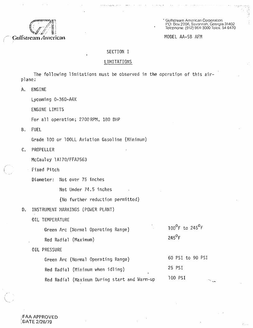
The following limitations must be observed in the operation of this airplane;
A. ENGINE
Lycoming 0-360-A4K
ENGINE LIMITS
For all operation; 2700RPM, 180 BHP
B. FUEL
Grade 100 or lOOLL Aviation Gasoline (Minimum)
C. PROPELLER
McCauley 1Al70/FFA7563
Fixed Pitch
Diameter: Not over 75 inches
Not Under 74.5 inches
(No further reduction permitted)
D. INSTRUMENT MARKINGS (POWER PLANT)
OIL TEMPERATURE
Green Arc (Normal Operating Range)
Red Radial (Maximum)
OIL PRESSURE
Green Arc (Normal Operating Range)
Red Radial (Minimum when idling)
Red Radial (Maximum During start and Warm-up
FAA APPROVED DA TE 2/26/79
l00°F to 245°F
245°F
60 PSI to 90 PSI
25 PSI
100 PSI

Culfstrcan1 Anicrican
TACHOMETER
Green Arc (Normal Operating Range)
Yellow Arc (Caution)
Red Radial (Maximum)
FUEL PRESSURE
Green Arc (Normal Operating)
Red Radial (Maximum)
Red Radial (Minimum)
E. AIRSPEED LIMITATIONS
NEVER EXCEED SPEED, VNE
MAXIMUM STRUCTURAL CRUISING SPEED, VNO
DESIGN MANEUVERING SPEEDS, VA
MAXIMUM FLAP EXTENDED SPEED, VFE
MAXIMUM CANOPY OPEN SPEED
F. AIRSPEED INDICATOR MARKINGS
Green Arc (Normal Operating Range)
Yellow Arc (Caution Range Smooth Air)
White Arc (Flap Operating Range)
Red Radial (Never Exceed Speed)
G. FLIGHT LOAD FACTORS
Normal Category (Gross Weight - 2400 lbs)
Flaps Up
Flaps Down
+3.89,
+3.5g
Utility Category (Gross Weight - 2050 lbs)
-1.52g
Flaps Up
Flaps Down
+4.4g, -l.76g
+3.5g
\.FAA APPROVED nA Tr: ? /?P./7Q
Gulfstream American Corporation PO. Box 2206, Savannah. Georgia 31402 Telephone: (912) 964-3000 Telex: 54 6470
MODEL AA-58 AFM
LIMITATIONS
2250 RPM to 2700 RPM·
1850 RPM to 2250 RPM
2700 RPM
0.5 PSI to 8 PSI
8 PSI
0.5 PSI
174 KCAS (174 KIAS)
143 KCAS (142 KIAS)
113 KCAS (112 KIAS)
104 KCAS (103 KIAS)
113 KCAS (112 KIAS)
56 KIAS to 142 KIAS
142 KIAS to 174 KIAS
52 KIAS to 103 KIAS
174 KIAS
Gtdfstrc·;.un A1ncrican
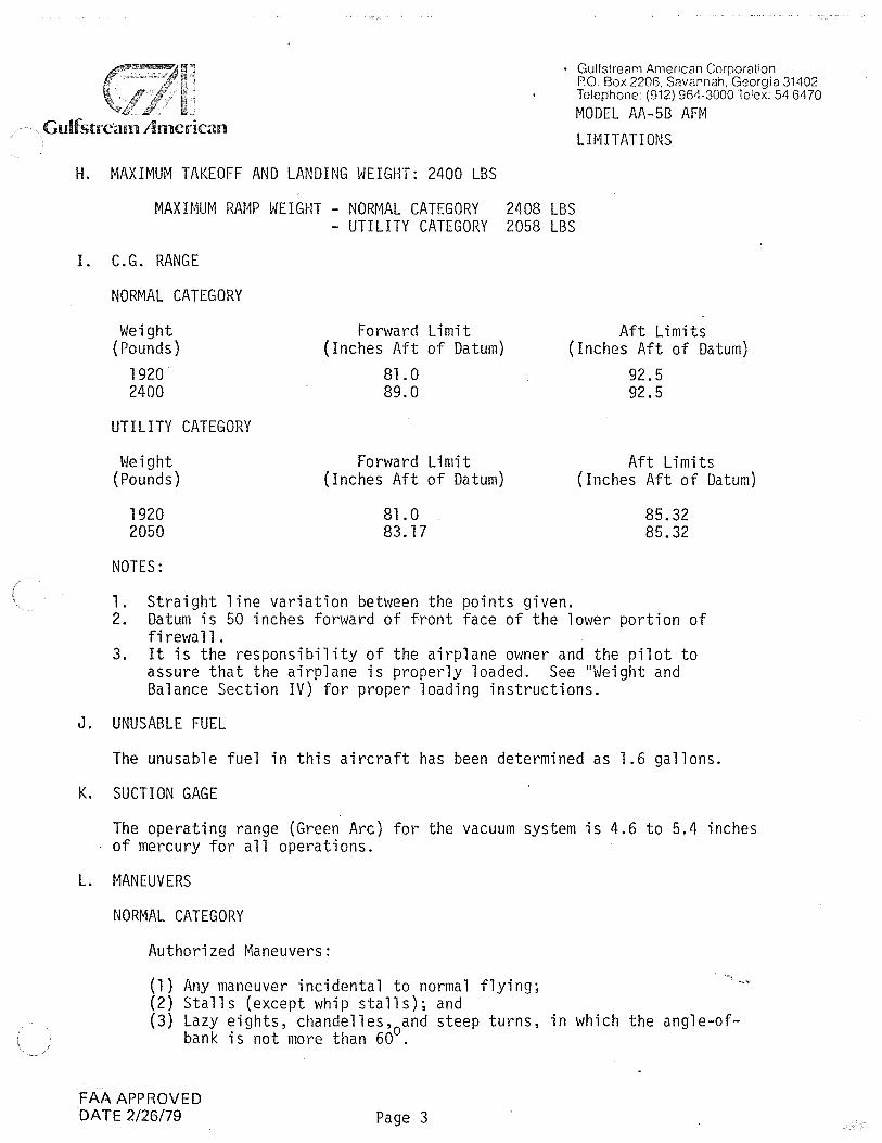
H. MAXIMUM TAKEOFF AND LANDING WEIGHT: 2400 LBS
• Gulfstream American Corporation P.O. Box 2206, Savannah, Georgia 31402 Telephone: (912) 964-3000 Telex: 54 6470
MODEL AA-5B AFM LIMITATIONS
MAXIMUM RAMP WEIGHT - NORMAL CATEGORY 2408 LBS - UTILITY CATEGORY 2058 LBS
I. C.G. RANGE
NORMAL CATEGORY
Weight {Pounds)
1920 2400
UTILITY CATEGORY
Weight (Pounds)
1920 2050
NOTES:
Forward Limit (Inches Aft of Datum)
81.0 89.0
Forward Limit (Inches Aft of Datum)
81.0 83.17
Aft Limits (Inches Aft of Datum)
92.5 92.5
Aft Limits (Inches Aft of Datum)
85.32 85.32
l. Straight line variation between the points given. 2. Datum is 50 inches forward of front face of the lower portion of
firewall. 3. It is the responsibility of the airplane owner and the pilot to
assure that the airplane is properly loaded. See "Weight and Balance Section IV) for proper loading instructions.
J. UNUSABLE FUEL
The unusable fuel in this aircraft has been determined as 1.6 gallons.
K. SUCTION GAGE
The operating range (Green Arc) for the vacuum system is 4.6 to 5.4 inches of mercury for all operations.
L. MANEUVERS
NORMAL CATEGORY
Authorized Maneuvers:
(l) Any maneuver incidental to normal flying; (2) Stalls (except whip stalls); and (3) Lazy eights, chandelles,
0and steep turns, in which the angle-of
bank is not more than 60 .
FAA APPROVED DA TE 2/26/79 Page 3

Gulfstream An1crican
Unauthorized Maneuvers:
All acrobatic operation including spins.
UTILITY CATEGORY
Gulfstream American Corporation P.O. Box 2206, Savannah, Georgia 31402 Telephone: (912) 964-3000 Telex: 54 6470
MODEL AA-SB AFM
LIMITATIONS
In the Utility Category, the baggage compartment and rear seat must not be occupied. No aerobatic maneuvers are approved except those listed below.
Maneuver Recommended Entry Speed
Chandelles Lazy Eights Steep Turns Stalls (Except Whip Stalls)
SPINS PROHIBITED
M. MAXIMUM PASSENGER SEATING CONFIGURATION
Three passengers (plus one pilot)
N. PLACARDS
112 KIAS 112 KIAS 112 KIAS Slow Deceleration
The following information is displayed in the form of composite or individual placards:.
( 1) In full view of the pilot:
THE MARKINGS ANO PLACARDS INSTALLED IN THIS AIR•
PLANE CONTAIN OPERATING LIMITATIONS WHICH MUST BE
COMPLIED WITH WHEN OPERATING THIS AIRPLANE IN THE
NORMAL CATEGORY. OTHER OPERATn<G LIMITATIONS
WHICH MUST BE COMPLIED WITH WHEN OPERATING THIS AIR•
PLANE IN THIS CATEGORY OR IN THE UTILITY CATEGORY
ARE CONTAINED IN THE Al RPLANE FLIGHT MANUAL
NORMAL CATEGORY -
DESIGN MANEUVERING SPEED VA -- -112 KNOTS IAS NO ACROBATIC MANEUVERS, INCLUDING SPINS, APPROVED
UTILITY CATEGORY-
DESIGN MANEUVERING SPEED VA - - -112 KNOTS IAS
REAR SEAT MUST NOT BE OCCUPIED
ACROBATIC MANEUVERS ARE LIMITED TO THE FOLLOWING .
MANEUVER ENTRYSPEEDIAS
CHANDELLES •••••• , ••• , ••••••• , • 112 KNOTS
LAZY EIGHTS , • , , , • , • , • •• • • , , ••• , 112 KNOTS
STEEP TURNS ••• • •• • ••• • • • • •••••• 112 KNOTS
STALLS (EXCEPT WHIP STALLS)--- SLOW DECELE.RATION
SPINS PROHIBITED
THIS AIRPLANE IS APPROVED FOR VFR, IFR, DAY ANO
NIGHT WHEN (QUIPPED IN ACCORDANCE WITH FAR 91.
THIS AIRPLANE IS NOT APPROVED FOR FLIGHT INTO
KNOWN ICING CONDITIONS.
5803007-131 AA·SB
FAA APPROVED DA TE 2/26/79

GuUstrcan11hncrican
(2) On control gust lock:
CONTROL LOCK
REMOVE BEFORE STARTING ENGINE
(3) On fuel selector valve:
ii LEFT FUEL \' 25.5 U.S. GAL.
~
RIGHT FUEL 25.5 U.S. GAL
0
FUEL SELECTOR LJ~ :::=====================::::ti
(4) Left side of instrument panel:
FOR FLIGHT WITH REAR SEAT OCCUPANTS AND/OR BAGGAGECARGO, CHECK WEIGHT & BALANCE
(5) Aft of fuel tank caps:
FUEL MIN 100/130 OCT,
26.3 U.S. GAL. TOTAL CAP. 19.0 U.S. GAL. TO TAB
(6) On instrument panel (if strobe lights are installed):.
TURN OFF STROBE IN CLOUD FOG OR HAZE.TAXI WITH STROBE. OFF
FAA APPROVED 01\ TE 2/26/79
. Gulfstream American Corporation P.O. Box 2206. Savannah, Georgia 31402 Telephone: (912) 964-3000 Telex: 54 6470
MODEL AA-SB AFM
LIMITATIONS
Gulfstrcairn Arncrican
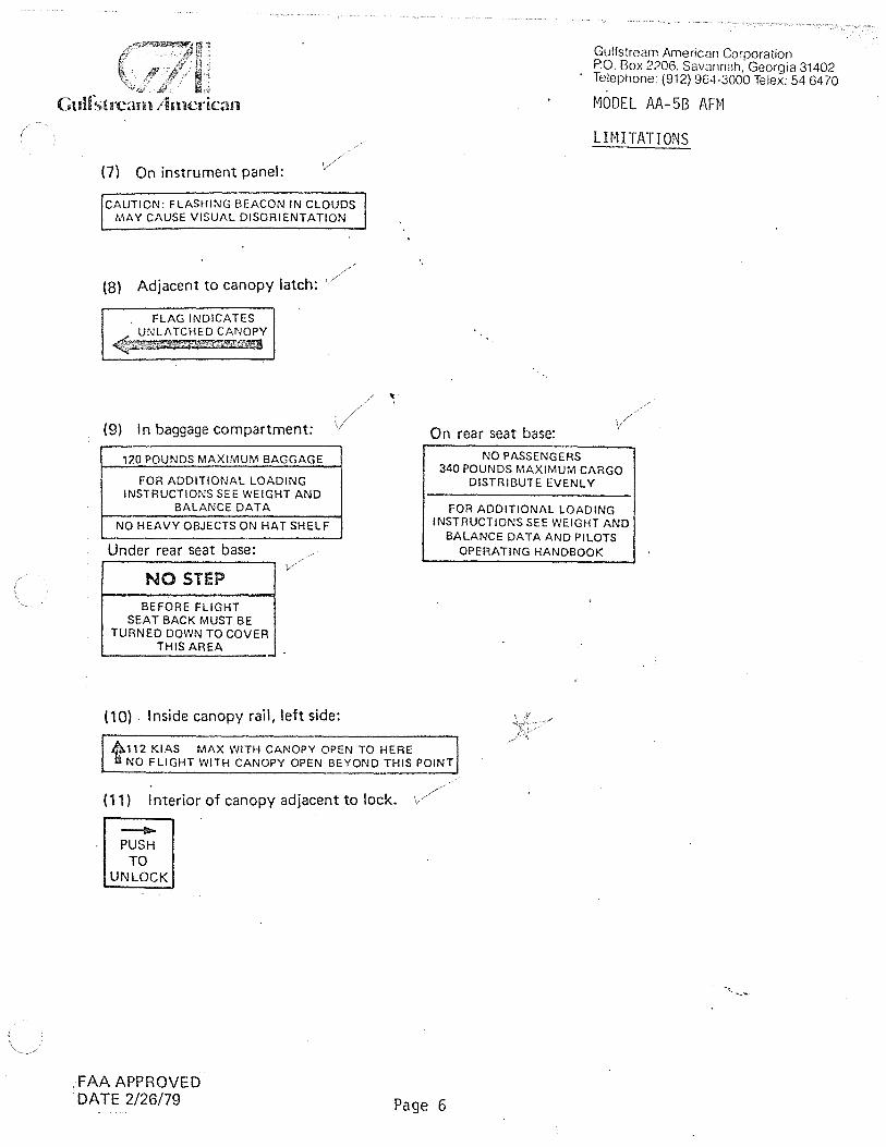
(7) On instrument panel:
CAUTION: FLASHING BEACON IN CLOUDS MAY CAUSE VISUAL DISORIENTATION
(8) Adjacent to canopy latch:
. FLAG INDICATES UNLATCHED CANOPY
~a:»W'''·&:t1:;iz;,z~
(9) In baggage compartment:
120 POUNDS MAXIMUM BAGGAGE
FOR ADDITIONAL LOADING INSTRUCTIONS SEE WEIGHT AND
BALANCE DATA
NO HEAVY OBJECTS ON HAT SHELF
Under rear seat base:
NO STEP
BEFORE FLIGHT SEAT BACK MUST BE
TURNED DOWN TO COVER THIS AREA
(10) . Inside canopy rail, left side:
On rear seat base: NO PASSENGERS
Gulfstream American Corporation PO. Box 2206. Savannah. Georgia 31402 Telephone: (912) 964-3000 Telex: 54 6470
MODEL AA-58 AFM
LIMITATIONS
340 POUNDS MAXIMUM CARGO DISTRIBUTE EVENLY
FOR ADDITIONAL LOADING INSTRUCTIONS SEE WEIGHT AND
BALANCE DATA AND PILOTS OPERATING HANDBOOK
A.112 KIAS MAX WITH CANOPY OPEN TO HERE 1f NO FLIGHT WITH CANOPY OPEN BEYOND THIS POINT
( 11) Interior of canopy adjacent to lock.
__..., PUSH
TO UNLOCK
FAA APPROVED DATE 2/26/79 Page 6

·ll J Gulfstrearn American
( 12) On wing outer ribs (it strobe lights are installed): ,
WARNING -HIGHVOLTAGE
WAIT 5 MINUTES AFTER SHUTTING OFF BEFORE STARTING
ANY WORK ON THIS UNIT
-CAUTIONTHIS UNIT POLARl1Y SENSiTIVE WHITE OR RED LEAD POSITIVE
BLACK LEAD AND OR CASE NEGATIVE
(13) Adjacent to auxiliary power plug (if installed):
CAUTION: 12 VOLT D.C. ONLY, MASTER SW. MUST BE OFF
(14) On instrument panel:
AVOID CONTINUOUS OPERATION BETWEEN 1850 & 2250 RPM WHILE DESCENDING
(15) On baggage door:
TO OPEN DOOR FROM INSIDE, ,, SLIDE HANDLE FORWARDic>
( 16) On glove box door:
TIRE PRESSURE NOSE 25 LBS MAIN 35 LBS
(17) On the oil filler cap.
OIL 8 QTS.
• Gulfstream American Corporation P.O. Box 2206, Savannah, Georgia 31402 Telephone: (912) 964-3000 Telex: 54 6470
MODEL AA-58 AFM
LIMITATIONS
(18) A calibration card is provided to indicate the accuracy of the magnetic compass in 30° increments
FAA APPROVED DA TE 2/26/79 Page 7

. Gulfstream American Corporation P.O. Box 2206, Savannah, Georgia 31402 Telephone: (912) 964-3000 Telex: 54 6470
Gulfatrcan1 Arncrican
SECTI_ON II
OPERATING PROCEDURES
A. NORMAL PROCEDURES
CHECKLISTS
1. Cabin (a) Canopy - OPEN (turn handle counterclockwise to open.) (b) Control Wheel Lock - REMOVE (c) Ignition Switch - OFF. (d) Master Switch - 0 FF (e) Mixture - I OLE CUTOFF.
2. Left Wing Trailing Edge (a) Flap - Secure and undamaged. (b) Aileron - Freedom of Movement
3. Left Wing (a) Wing Tip and Light - Undamaged (b) Aileron Counterweight Access - Unobstructed (c) Wing Inspection Plates - Secure {d) Tiedown - Removed (e) Pitot Tube - Unobstructed (f} Fuel Tank Vent - Unobstructed
4. Left Wing Leading Edge
....
(a) Fuel Tank - Full, cap seal checked for damage, cap secure (b) Tank Drain - Fuel free of water and sediment, drain secure (c) Sump Drain - Fuel free of water and sediment, drain secure (d) Fuel - Proper color
MODEL AA-5B AFM OPERATING PROCEDURES
(e) Landing Gear Wheel Fairing and Tire - Undamaged, tire properly inflated (f) Chocks - Removed
5. Left Cowling (a) Windshield - Clean, undamaged (b) OAT Gauge - Secure, undamaged (c) Fuel Pump Overflow Drain - Unobstructed (d) Fresh Air Vents - Unobstructed (e) Air Cleaner Drain - Unobstructed (f) Oil Breather Vent - Unobstructed (g) Cowling - Open, secured (h) Baffles - Secure, Undamaged (i) Cowling - Closed, latches secured (flush with surface)
FAAAPPROVED DA TE 2/26/79
NOTE
If engine cowling is opened, ensure that its support· tube is secured in the retainer clip prior to closing the cowling. Ensure that cowling latches are secure (flush with surface).
Page 8

Culfstrcarn Arncrican
6. Nose (a) Propeller and Spinner - Secure, undamaged (b) Cowling - Secure, undamaged (c) Landing Light - Secured, undam<iged
1..:1u11::,uewrr /\rnenccm vorporarn:.in--PO __ Box 2206. Scivannah Georoia 31402 Telephone: (912) 964-3000 Telex: 54 6470
MODEL AA-58 AFM OPERATING PROCEDURE
(d) Nose Gear, and Fairing - Undamaged, tire properly inflated, mud scraper clear (e) Tow Bar - Removed and stowed (f) Chocks - Removed (g) Engine Cooling Openings - Unobstructed
7. Right Cowling (a) Cowling - Open (b} Carburetor Air Duct - Unobstructed (c) Engine Cooling Openings - Unobstructed (d) Engine Oil Level - 6 Quarts minimum, capacity 8 quarts (e) Engine Oil Dipstick - Secured (finger tight} (f) Vacuum Pump Vent - Unobstructed (g) Battery - Secure (h) Alternator Belt - Proper tension (i) Baffles - Secured, Undamaged (j) Cowling - Closed, latches secured (flush with surface)
8. Right Wing Leading Edge (a) Fuel Tank - Full, cap seal checked for damage, cap secured (b) Tank Drain - Fuel free of water and sediment, drain secured (c) Sump Drain - Fuel free of water and sediment, drain secure (d) Fuel - Proper color , (e) Landing Gear, Wheel Fairing and Tire - Undamaged, tire properly inflated (f) Chocks - Removed (g) Stall Warning Vane - Check
9. Right Wing (a) Wing Tip and Light - Undamaged (b) Aileron Counterweight Access - Unobstructed (c) Wing Inspection Plates - Secured (d) Tiedown - Removed (e) Fuel Tank Vent - Unobstructed
10. Right Wing Trailing Edge (a) Aileron - Freedom of movement (b) Flap - Secure and undamaged
11. Right Side of Fuselage (a) Static Source - Unobstructed (b} Antennas - Secure, undamaged (c) Fuselage - Undamaged
12. Empennage (a) Elevators - Freedom of movement (b) Rudder - Freedom of movement (c) Trim Tabs - Secure, undamaged (d) Tail Cone and Light - Secured, undamaged (e) Tie Down - Removed
FAA APPROVED DATE 2/26/79 Pa

Gulfstrc:un J11ncrican
13. left Side of Fuselage (a) Static Source - Unobstructed (b) Fuselage - Undamaged (c) Baggage Door - Secure
14. Night Flight Preflight (a) Fuses and Circuit Breakers - Cht)ck (b) Spare Fuses - In Mop Compartment (c) Flashlight - Aboard (d) Required Charts - Aboard
ELECTRICAL SYSTEMS PREFLIGHT
1. Cabin (a) Master Switch - ON (b) Instrument Lights - Check Rheostat, OFF (c) Map Light and Dome Light - ON (d) Navigation lights - ON (e) Flashing Beacon - ON (f) Strobe Lights - ON (g) Pitot Heat - ON (h) landing Light - ON
2. left Wing Tip (a) Navigation light - Illuminated ': (b) Strobe Light - Flashing
WARNING
DO NOT TOUCH PITOT TUBE DIRECTLY, IT CAN BE HOT ENOUGH TO BURN SKIN.
(c) Pitot Tube - Check for heat
3. Nose (a) landing Light - Illuminated
4. Right Wing (a) Stall Warning Vane - Lift, check that stall warning horn sounds
5. Right Wing Tip {a) Navigation Light - Illuminated
· (b) StrQbe Light - Flashing
6. Empennage (a) Navigation Light - Illuminated (b) Flashing Beacon - Operating
FAA APPROVED DATE 2/26/79 Page 10
Gulfstream American Corporation P.O. Box 2206. Savannah, Georgia 31402 T~lephone: (912) 964-3000 Telex: 54 6470
MODEL AA-58 AFM OPERATING PROCEDURE

Gulf strca1n A1ncrican
7. · Cabin ' (al Master Switch - OFF·
(b) Navigation Lights - OFF (c) Flashing Beacon - OFF (d) Strobe Lights - OFF (e) Pitot Heat - 0 FF (f) landing Light - OFF
BEFORE STARTING ENGINE
( 1) Preflight Inspection - Complete (2) Seats, Seat Belts and Shoulder Harness - Adjusted, locked .(3) Radios, Autopilot, Electrical Equipment - OFF (4) Parking Brake - SET (5) Controls - Check for proper operation
STARTING ENGINE
Airplane Power
( 1) Master/ Alternator Switch - ON (2) Mixture - FULL RICH (3) Carburetor Heat - 0 FF (4) Fuel Selector Valve - Set to fullest tank (5) Prime - As required (6) Flaps - UP {7) Auxiliary Fuel Pump - ON (Check pressure 0.5 - 8 PSI) (8) Propeller - CLEAR (9) Ignition Switch - ON LEFT
(10) Throttle - Open approximately 1/4-inch (11) Starter Button - Press, release when engine starts (12) Ignition Switch - ON BOTH
Gulfstream American Corporation P.O. Box 2206. Savannah. Georgia 31402 T~lephone: (912) 964-3000 Telex: 54 6470
MODEL AA-58 AFM OPERATING PROCEDURE
'" I, I 1 _ ~ ..
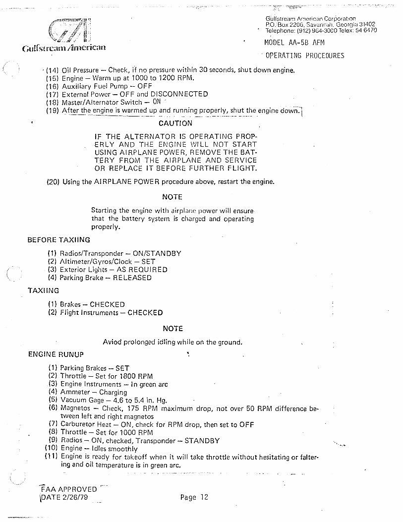
(13) Oil Pressure - Check, if no pressure within 30 seconds, shut down engine (14) Engine - Warm up at 1000 to 1200 RPM (15) Auxiliary Fuel Pump - OFF
External Power
(1) Master/Alternator Switch -OFF (2) External Power - SET FOR 12 VOL TS, CONNECTED. (3) Mixture - FULL RICH (4) Carburetor Heat - OFF (5) Fuel Selector Valve - Set to fullest tank (6) Prime - As Required. (7) Flaps - UP . (8} Auxiliary Fuel Pump - ON (Check pressure 0.5 to 8 PSI) (9) Propeller - CLEAR
(10) Ignition Switch - ON LEFT (11) Throttle - Open approximately 1/4 inch · ( 12) Starter Button - Press, release when engine starts. (13) Ignition Switch - ON BOTH .
FAA APPROVED DATE 2/26/79 Page 11
Gulf strenn /1n1crkan
Gulfstream American Corporation P.O. Box 2206, Savannah. Geor~Jia 31402 Telephone: (912) 964-3000 Telex: 54 6470
MODEL AA-58 AFM
OPERATING PROCEDURES
· (14) Oil Pressure - Check, if no pressure within 30 seconds, shut down engine. (15) Engine - Warm up at 1000 to 1200 RPM. (16} Auxiliary Fuel Pump - OFF (17) External Power - OFF and DISCONNECTED (18) Master/ Alternator Switch - ON (19) ~~ter_!_~~~ngine is ~~.e~~£> ~~? ru~_ni.n~.~~~-~e!!X~~~~t_!.~e engine down-~
CAUTION
IF THE ALTERNATOR IS OPERATING PROPERLY AND THE ENGINE WILL NOT START USING AIRPLANE POWER, REMOVE THE BATTERY FROM THE Al RPLANE AND SERVICE OR REPLACE IT BEFORE FURTHER FLIGHT.
(20) Using the AIRPLANE POWER procedure above, restart the engine.
NOTE
Starting the engine with airplane power will ensure that the battery system is charged and operating properly.
BEFORE TAXIING
( 1) Radios/Transponder - ON/ST AN OBY (2) Altimeter/Gyros/Clock - SET (3) Exterior Lights - AS REQUIRED (4} Parking Brake - RELEASED
TAXIING
(1) Brakes - CHECKED (2) Flight Instruments - CHECKED
NOTE
Aviod prolonged idling while on the ground.
ENGINE RUN UP
(1) Parking Brakes - SET (2) Throttle - Set for 1800 RPM .(3) Engine Instruments - In green arc (4) Ammeter - Charging (5) Vacuum Gage - 4.6 to 5.4 in. Hg. (6) Magnetos - Check, 175 RPM maximum drop, not over 50 RPM difference be-
tween left and right magnetos (7} Carburetor Heat - ON, check for RPM drop, then set to OFF (8) Throttle - Set for 1000 RPM (9) Radios - ON, checked, Transponder- STANDBY
(10) Engine - Idles smoothly (11) Engine is ready for takeoff when it will take throttle without hesitating or falter
ing and oil temperature is in green arc.
FAA APPROVED \DA TE 2/26/79 Page 12

Gulfstream American Corporation P.O. Box 2206, Savannah. Georgia 31402 Telephone: (912) 964-3000 Tolcx: 54 6470
MODEL AA-5B AFM Culfstrcan1 Arncrican OPERATING PROCEDURES
BEFORE TAKEOFF
(1) Trim Tab-SET (2) Flaps - Checked for operation, set UP (3) Mixture - FULL RICH (or as required by field elevation) (4) Throttle Friction Lock - ADJUSTED (5) Auxiliary Fuel Pump - ON, check for pressure change, then set to OFF (6) Flight Instruments - SET (clock, directional gyro, altimeter, radios) (7) Lights - ON, as required (8) Parking Brake - OFF (9) Seat Belts and Shoulder Harness - SECURE
(10) Transponder - ON
TAKEOFF
NORMAL TAKEOFF
(1) Flaps-UP (2) Carburetor Heat - OFF (3) Auxiliary Fuel Pump - ON (4) Throttle - FULL OPEN (5) Elevator Control - Raise nosewheel at 50 KIAS to 55 KIAS (6) Climb Speed - 90 KIAS
OBSTACLE CLEARANCE TAK EOFF
(1) Flaps - UP (2) Carburetor Heat~-.Qfl~\R (3) Auxiliary Fuel'Pump _j~'tJN (4) Throttle - FULL OPEN (5) Elevator - Apply light back pressure at 50 KIAS, lift nose~heel at 55 KIAS (6) Climb Speed - 65 KIAS
CLIMB
(1) Normal Climb Speed - 90 KIAS at full throttle (2) Best Rate of Climb Speed - 90 KIAS at sea level, full throttle (3) Best Angle of Climb Speed - 70 KIAS at sea level, full throttle
CRUISE
(1) Auxiliary Fuel Pump - OFF (2) Power - SET at 2200 to 2700 RPM (3) Trim Tab - SET as required (4) Mixture - SET as required. Full rich when operating at more than 75% power. If
in doubt of percentage of power being used, use full rich mixture for operation below 5000 ft.
CAUTION
DO NOT OPEN CANOPY AT SPEEDS IN EXCESS OF 112 KIAS.
FAA APPROVED DA TE 2/26/79 Page 13
·,

Gulfstrca1n Arncrican
DESCENT
( 1) Power - As required for descent
NOTE
While descending avoid continuous operation at engine speeds between 1850 and 2250 RPM.
(2) Mixture - As required by altitude
Gulfstream Americ;m Corporation P.O. Box 2206, S;w;innah. Georgia 31402 Telephone (912) 964-3000 Telex: 54 6470
MODEL AA-513 AFM
OPERATING PROCEDURES
(3) Carburetor Heat - As required by engine power setting and weather conditions (4} Trim Tab - SET as required
BEFORE LANDING
( 1) Seats, Seat Belts and Shoulder Harness - Adjust and lock (2) Fuel Selector - On fullest tank (3) Mixture - FULL RICH (4) Auxiliary Fuel Pump - ON (5) Carburetor Heat - as required. (6) Parking Brake - OFF (7) Flaps - SET as required, below 103 KIAS (8) Landing Light - ON as required.
BALKED LANDING
(1) Power - Full throttle (2) Carburetor Heat - OFF (3) Airspeed - 70 Kl AS (4) Establish Climb Attitude (5) Flaps - Retract slowly, (6) Airspeed - Accelerate to 90 KIA~
LANDING
NORMAL LANDING
( 1) Touch down on ma in gear.
CAUTION
IF THE NOSE GEAR IS ALLOWED TO CONTACT THE RUNWAY PRIOR TO MAIN GEAR TOUCHDOWN A PORPOISE MANEUVER MAY OCCUR. SHOULD THE AIRPLANE BEGIN PORPOISING RECOVER AS FOLLOWS: (a} APPLY FULL POWER (b) MAINTAIN STEADY ELEVATOR BACK
PRESSURE FOR A NORMAL CLIMB. (c) ESTABLISH A NORMAL CLIMB AT 90
KIAS (d) SLOWLY RETRACT FLAPS (e) EXECUTE A NORMAL GO-AROUND.
FAA APPROVED DATE 2/26/79 Paqe 14
-,_

Gulfstrcan1 Anierican
• (2) Lower nosewheel slowly as speed decreases.
Gulfstream American Corporation PO. Box 2206, Savannah, Georgia 31402 Telephone: (912) 964-3000 Telex: 54 6470
MODEL AA-58 A.FM
, OPERATING PROCEDURES
(3) Use rudder to maintain directional control down to approximately 20 KIAS. (4) Brakes - Use as required for stopping and directional control.
AFTER LANDING
(1) Flaps-UP (2) Auxiliary Fuel Pump - OFF (3) Landing Light - OFF {if used} (4) Carburetor Heat - OFF (5) Strobe Light-:- OFF {if used)
SHUT-DOWN/SECURING AIRPLANE
(1) Electrical Equipment, Radios, Lights - OFF (2} Mixture - IDLE CUTOFF (3) Ignition - 0 FF (after propeller has stopped) (4) l'v'aster Switch - OFF (5) Control Lock - Installed (6) Parking Brake - SET (7) Chocks/Tiedowns - Installed (8) Parking Brake - OFF
FAA APPROVED DATE 2/26/79 Page 15
-•.

·,,;
.. Gulfstream Arncrican
NORMAL TAKEOFF PROCEDURE
• Gulfstream American Corporation . PO. Box 2206, Savannah, Georgia 31402 Telephone: (912) 964-3000 Telex: 54 6470
MODEL AA-5B AFM
Before beginning the takeoff roll, align the airplane with the runway. Aligning the nose wheel with the takeoff direction will allow minimum brake usage during the initial ground roll. When full power is applied for takeoff, directional control is maintained with light toe pressure on the brakes. At speeds above 15 KIAS to 20 KIAS, the rudder becomes fully effective and brake steering is NOT necessary. Continued use of brake steering will only prolong the takeoff roll.
Accelerate to 50 KIAS before applying a light back pressure on the control wheel to lift off the nose wheel. Raising the nose wheel too soon or to an excessive angle may increase takeoff ground distance. When airborne, accelerate to the desired climb speed.
MAXIMUM PERFORMANCE TAKEOFF PROCEDURES
After alignment in the takeoff direction, hold the brakes to prevent movement and apply full throttle. When full power is reached, release and begin the takeoff roll with the elevator neutral. Use light smooth brake pressures to maintain low speed directional control. At 55 KIAS apply elevator back pressure for rotation, then climb at 65 KIAS below 50 ft. If terrain or further obstacles are to be cleared after-takeoff and above the 50-foot obstacle, accelerate to the best angle-o~-climb speed - 70 KIAS at sea level. When obstacles are cleared, accelerate to the desired climb speed.
NORMAL CLIMB PROCEDURE
A normal climb speed of 90 KIAS is recommended once all ground obstacles have been cleared. This speed offers good visibility, excellent over-the-ground speed and rate of climb. The best rate-of-climb soeed varies from 90 KIAS at sea level to 79 KIAS at 10,000 ft. The best angle-of-climb speed varies from 70 KIAS at sea level to 72 KIAS at 10,000 ft.
NORMAL LANDING PROCEDURE
Full flaps and main wheels first are recommended for a normal landing.
BALKED LANDING PROCEDURE
Should a landing be balked, apply full power immediately; carburetor heat OFF; establish a positive rate of climb at 70 KIAS,retract the flaps and trim for normal climb.
CROSSWIND PROCEDURE Crosswind Takeoff The airplane is accelerated to a speed slightly higher than normal, the·n
flown off abruptly to prevent possible settling back to the runway while drifting. When clear of the ground, make a coordinated turn into the wind to correct for drift.
FAA APPROVED DA TE 2/26/79 Page 16

·Culfstrcan1 Amncrican
Crosswind Landing
.Gulfstream American Corporation P.O. Box 2206, Savannah. Georgia 31402 Telephone: (912) 964-3000 Telex: 54 6470
MODEL AA-5B AFM
When landing in a strong crosswind, use the m1n1mum flap setting required for the field length. Although the crab or combination method of drift correction may be used, the crab method gives the best control. After touchdown, hold a straight course with the rudder and occasional braking.
B. EMERGENCY PROCEDURES
Enoine Fire
a. In case of an engine fire in flight:
1. Mixture - IDLE CUTOFF 2. Fuel Selector Valve - OFF 3. Master Switch - OFF 4. Cabin Heat and Air - OFF 5. Airspeed - 115 KIAS If fire is not extinguished, increase glide
speed to attempt to blow the fire out. 6. Forced Landing - EXECUTE (as described in Landing Without Engine
Power).
b. In case of carburetor induction fire on the ground:
1. Cranking - CONTINUE to get a start which would suck the flames and accumulated fuel through the carburetor and into the engine.
If engine starts:
2. Power - 1800 RPM for a few minutes. 3. Engine - SHUTDOWN and inspect for damage.
a. Fuel Selector - OFF b. Master Switch - OFF c. Ignition Switch - OFF
If engine fails to start:
4. Evacuate passengers. 5. Engine - SECURE
a. Mixture - IDLE CUTOFF. b. Master Switch - OFF. c. Ignition Switch - OFF. d. Fuel Selector Valve - OFF.
6. Fire - EXTINGUISH using fire extinguisher, seat cushion, wool blanket, or dirt.
FAA APPROVED DA TE 2/26/79
-,
Page 17

Gulfstrcmn Aancrican
Engine Failure During Takeoff
a. Engine Failure During Takeoff Run
1. Throttle - IDLE 2. Brakes - APPLY 3. Mixture - IDLE CUTOFF 4. Ignition Switch - OFF 5. Master - OFF.
b. Engine Failure Immediately After Takeoff
1. Mixture - IDLE CUTOFF 2. Fuel S~lector Valve - OFF 3. Ignition Switch - OFF 4. Master Switch - OFF
Engine Failure During Flight
l. Airspeed - 72 KIAS 2. Carburetor Heat - ON 3. Fuel Selector Valve - SWITCH TANKS 4. Mixture - RICH 5. Master Switch - ON 6. Auxiliary Fuel Pump - ON 7. Throttle - OPEN 1/4 inch 8. Ignition Switch - BOTH 9. Primer - IN and LOCKED
10. Starter - PRESS if propeller is stopped.
Electrical System Emergency Procedures
a. Electrical Fire in Flight
If fire is in engine compartment:
1. Master Switch - OFF 2. Vents/Cabin Air/Heat - OFF/CLOSED 3. Land airplane as soon as possible
If fire is in cockpit:
l. Master Switch - OFF
·Gulfstream American Corporation P.O .. Box 2206. Savannah, Georgia 31402 Telephone: (912) 964-3000 Telex: 54 64 70
MODEL AA-58 AFM
OPERATING PROCEDURES
2. All Other Switches (except ignition switch) - OFF 3. Vents/Cabin Air/Heat - CLOSED 4. Fire Extinguisher - ACTIVATE (if available}
FAA APPROVED DA TE 2/26/79 Page 18

Culfstrcarn Arncrican
Gulfstream American Corporation PO Box 2206, Savannah. Georgia 31402 Telephone: (912) 964-3000 Telex: 54 6470
MODEL AA-5B AFM
OPERATING PROCEDURES
If fire appears to· be out and electrical power is necessary to continue flight:
5. Master Switch - ON 6. Circuit Breakers - CHECK for faulty circuit, do not reset. 7. Radio/Electrical Switches - ON one at a time, with delay after
each until short circuit is located. 8. Vents/Cabin Air/Heat - OPEN when fire is out.
b. Ammeter Shows Discharge
1. Alternator Circuit Breaker - Check
NOTE
If circuit breaker trips, wait 15 seconds before resetting it.
2. Field Circuit Breaker - Check 3. If Field Circuit Breaker is tripped, land as soon as practical. 4. If Field Circuit Breaker is not tripped, and ammeter continues to
show discharge, set alternator side of master switch to OFF and land as soon as practical.
Vacuum System Failure
A vacuum system failure may disable the directional and attitude indicators, thus forcing the pilot to rely on the turn coordinator or turn-and-bank indicator if he inadvertently flies into clouds.
Static Source Blocked
If erroneous readings are suspected on the instruments associated with the pitot-static system (airspeed indicator, altimeter and vertical speed indicator) pitot heat should be applied (for erroneous airspeed indications) in case the problem is due to ice or water accumulation in the pitot head. Failure of pitot heat to correct the problem may indicate blockage of the static sources. Obviously in a situation such as this, a landing should be planned at the nearest suitable airport. If it is necessary to continue the flight, and particularly if the flight is in marginal conditions, a static source must be supplied to the airspeed indicator and altimeter.
If an alternate air source is installed on your airplane, a static air source can be applied to these instruments by pulling out the ALT-STATIC AIR va~ve located on the left side of the instrument panel.
FAA APPROVED DATE 2/26/79 Paqe 19

Gulfst1·can1 A1ncrican
NOTE
Gulfstream American Corporation PO. Box 2206, Savannah, Georgia 31402 Te)ephone: (912) 964-3000 Telex: 54 6470
MODEL AA-5B AFM
OPERATING PROCEDURES
Close the canopy when using alternate static air source. At airspeeds above 87 KIAS subtract 6 KIAS from indicated airspeed and 80 feet from indicated altitude.
If your airplane is not equipped with an alternate static air source, a static source can be supplied to the airspeed indicator and altimeter by breaking the glass on the face of the vertical speed indicator.
If this is done, remember the following:
1. The vertical speed indicator will be inoperative. 2. Some error may be expected in airspeed and altitude indications.
At airspeeds above 87 KIAS subtract 6 KIAS from indicated airspeed and 80 feet from indicated altitude.
3. The canopy must be kept closed, since opening it could introduce large errors in airspeed and altitude indications.
FAA APPROVED DATE 2/26/79 Page 20

,t;,'I_/
Culfstrcarn Arncrican
A. Altitude Lost in Stall
SECTION I I I
PERFORMANCE
• Gulfstream American Corporation PO. Box 2206, Savannah, Georgia 31402 Telephone: (912) 964-3000 Telex: 54 6470
MODEL AA-5B AFM
PERFORMANCE
The maximum altitude lost in a normal stall recovery is approximately 350 feet.
B. Engine Cooling
Engine cooling ha6 been satisfactorily demonstrated for an outside air temperature of 23 C above standard. This temperature is not to b~ considered an operating limitation.
C. Condition for Usable Fuel
The maximum usable fuel, as determined by the most critical flight profile, is available for any reasonable flight condition.
D. Airspeed Calibration - Normal System
Note: 12
•• KIAS assumes zero instrument error. Corrections are not affected by flap position.
FAA APPROVED DA TE 2/26/79
KIAS KCAS
50 50 60 60 70 70 80 81 90 91
100 101 110 111 120 121 130 131 140 141 150 150 160 160 170 170 180 180
· Page 21

Gulfstrca1n Aincrican
SECTION IV
WEIGHT AND BALANCE
. Gulfstream American Corporation PO. Box 2206, Savannah, Georgia 31402 Telephone: (912) 964-3000 Telex: 54 6470
MODEL AA-5B AFM
WEIGHT AND BALANCE
It is the responsibility of the pilot-in-command to calculate the weight and center-of-gravity position of the aircraft and insure the calculated weight and center of gravity are within the prescribed weight and center-ofgravity limitations.
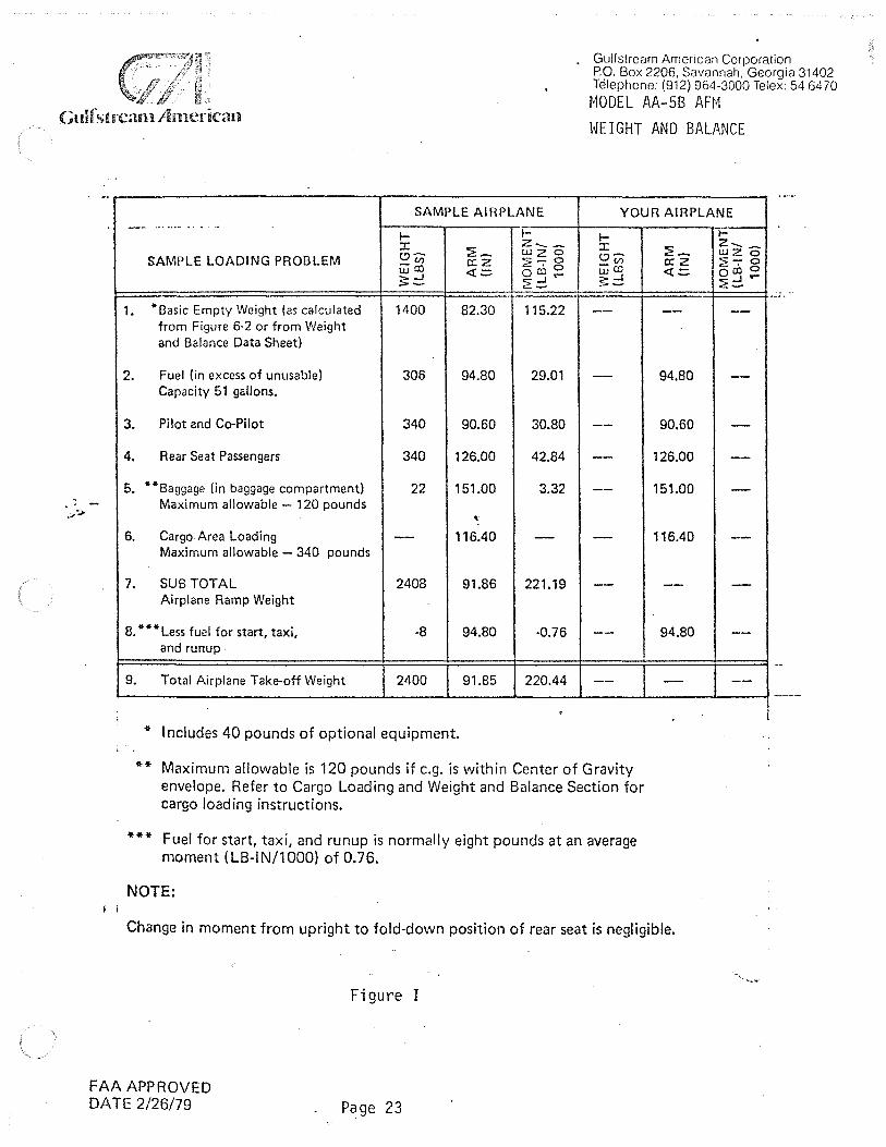
The following information will enable you to fly your AA-5B Tiger within the prescribed weight and center-of-gravity limitations. To calculate the weight and balance for your AA-58 Tiger, use the Sample Problem (Figure 1), Loading Graph (Figure 2) and Center of Gravity Envelope (Figure 3) charts as follows:
Write down the "Basic Empty Weight" and "Moment" on the Sample Loading Problem chart (Figure 1) under the column marked "Your Airplane 11 from the Weight and Balance Data Sheet (and/or changes listed on FAA Form 337) included with your airplane papers. Also add all additional weights and their corresponding moments (obtained from the 11 Loading Graphs") of items to be carried on in flight. Plot the total weight and moment on the "Center of Gravity Envelope" chart (Figure 3) and if the intersection is within the envelope, the loading is acceptable.
FAA APPROVED .DATE 2/26/79 Page 22
Gulfstream American Corporation PO. Box 2206. Savannah. Georgia 31402 Telephone: (912) 964-3000 Telex: 54 6470
MODEL AA-58 AFM WEIGHT AND BALANCE
Gulf 'it rcan1 An1crican
SAMPLE AIRPLANE YOUR AIRPLANE
• i
-- ·····-·· .... ,.
I- I- I-:I: :2: ~
z....__ :I: o~ UJ 2 0 o~ SAMPLE LOADING PROBLEM _(I) 0:2 2- 0 _(I) UJ co
<l: = 0 cC 0 UJ cc S:2 ...J .... ?- ...J
2~ -~
1. "Basic Empty Weight (as calculated 1400 82.30 115.22 --from Figure 6-2 or from Weight and Balance Data Sheet)
2. Fuel (in excess of unusable) 306 94.80 29.01 --Capacity 51 gallons.
3. Pilot and Co-Pilot 340 90.60 30.80 --4. Rear Seat Passengers 340 126.00 42.84 --
5. **Baggage On baggage compartment) 22 151.00 3.32 --Maximum allowable - 120 pounds
' ' 6. Cargo Area Loading -- 116.40 - -
Maximum allowable - 340 pounds
7. SUB TOTAL 2408 91.86 221.19 --Airplane Ramp Weight
8. ***Less fuel for start, taxi, ·8 94.80 ·0.76 --and runup
9. Total Airplane Take-off Weight 2400 91.85 220.44 --
* Includes 40 pounds of optional equipment.
** Maximum allowable is 120 pounds if e.g. is within Center of Gravity envelope. Refer to Cargo Loading and Weight and Balance Section for cargo loading instructions.
*** Fuel for start, taxi, and runup is normally eight pounds at an average moment (LB-IN/1000) of 0.76.
NOTE:
:2: ~ 0: z <l: .::.
--
94.80
90.60
126.00
151.00
116.40
--
94.80
--
Change in moment from upright to fold-down position of rear seat is negligible.
FAA APPROVED DA TE 2/26/79
Figure I
Page 23
I-z._ -wz 0 2'7 0 0 co 0 :?.:2 ....
--
-
-
--
--
--
-
--

0 .,., )>)> -1> m> N '"ti
N" C"l :0 "'0 <5<
'"'O PJ
r..a ro N ~
m 0 400
350
300 (/)
CJ ,, z ..... ::> (.Q 0 250 c c.. -s
2 ro ,_. I-,_. :I: 200
(.!'
w ~ I 150
CJ <t 0 ..J
100
50
450mmmw™1•mim -.-.-.---~ - T i)'
· I I I I l+.+-W+++- 11- V $l w - Pt LOT & CO· Pl LOT .;,_ - ·- - -'- ~ ...... j- ·t 1· t - 1 ·v · - ·--~- --·- --bv ___ ...._
-~1-~- - _,_.__..__ ~ .... - v V\ ·t-·f-4-- I
. --- - - + -....... ---/i·- ·- --r-'v --~ - l/ - - - - -------~-~--·- . ----l---. ----·-·-·-f--rt-~-C:JI~ --
;_ ---- ·- - - -·~ - ) ·- f- -- -- - ~t· 1-- - -- ·- - -
I I I I 1-f-+-++-+- · --'- -- - -1.- _.._L 306 lb ·- --.Lf+- t' >-·- · --- -m~u,E~us~a~lo;-Glbs./gal.) f'·' ,'· ~~, 7~CARGO • - I -- 11'1;~ - - --v--/ n I Lt--H+fBm· t .L ..._,_ -f.1 ~ .. - -'-•-v -•· ,,, . ·*!+ §~ WJJJ!ttllE- i i 7' . r._..._ _._ v,_ .. t.r. ~-- _LJ.J.J .. L, . . .. i
H-4--H'. c: . i., , ·" ·· v 1,,. REAR SEAT PASSENGERS 1m----- :~"'' J :,;1<'" c·" - - -:n ..... --1--t-t-· . ............,_, .. __ ._
::: · -~-·- ...... i-Yv -···-17·-1:.-1" ·· -+-+-+j-·ttttl I I I I I t ·r:;V:: 11 ...... ~ .1,,.. ··t> ' - -~ - - -...J-+.-1- -
SftB ~:£~ • _,__(/._.L...L ... O .. l... -~ ... ··•f- .. I I , 1,- ,. I I I I .. - l)Y't7 - ·--•-'- - ->- - ... -1-- _.._. •- 1-•-·. - - --- . f ~--·r;.• f/'- · -'-'- · - - ··-->-- -H-•- ..• J+ +t-H-
~ ::.--1-v :l.--i.... ·- I I I 1-,r \;': I I I I
Ill Ill I ~~jr;.1;-i-- ...... ~.-- II I I I I I I :./ T.;Vl. ...... ~ .. , .......... ~.•- -~
I I I I I I I - -vt:;lf i;, • ,_,_ - -- ->--f- _._._LJ_ -.1" Vv .. 1/ Add weight of items to be carried to basic empty weiriht. _
V/ l/ •
1-+-+-+-tttt,~ ;;':C'.!r' Add moment/1000 of items to be carried to basic empty :
£~~VtrJ'.'."._lli weight momr.nt/1000. Use Center of Gravity Envelope to_ H-+-++-f V -l.-t' __ ,__ - . . . . -
r~-:: v dctermrnc acceptabil1ty (Figure 6-5). H
l:±:Ht ~ BAGGAGE _,_._{-f .. l I I I I I I I t I I l I I -j Ffi7_..,;(-1 I I I I :rt
otK1 I I ·'-'--1--1-1-l-+++-I I I I I I ! I I I I I I I I I I I I I I I
0 5 10 ·15 20 25 30 35 40 45 50 55
EXAMPLE: MOMENT/1000 INCH POUNDS
250 pounds of fuel is at a moment of 24 ( 1000) inch pounds.
-.. ' -:::... -J.. .... -. r-: .. --,., ... .... -... ... ... ~ ""l
~· ~' = ...
~ 3: ~:-OQ ::::! §5«:io§: Ci") rr1 :2. ClJ ~ -r I -'O ..... =i 5 :.: 2
:J> .... r...i -> > :- f\) =· -:?' I -;;:;O> 0 u-i ::;:Cl:;
co~(;,(5 co :;i::.cn~g )> CJ CJ O•
~ ~ ~~~ z 5e>~ .. / <J o:r~ rr1 o· D
_.oo ::;..:g ii) c:i_::::x l.D 0 .. - ::i (J1 Ill ..,.w m~ ..,,_.,,, -...iO 01\)

0"'l1 >l> 4> m> IV '"'() -., ~ ::0 -o c:cl <
m 0
-0
°' (Q CD
N (J1
I en 0 2 ::::> 0 0.
2
!-:I:
""T1 (!)
...... w (Q $: c: w -s CD 2
~ ....... ...I ....... 0. ....... a:
~ 0 w 0 ~ 0 ...I
2200 '. . ~· t I I -;;. . . .-1
. ..
1
, mill ~ ~,-n ~ --. -1 , 1- i 1 •-+- - -~- ... _.__. t ·- · - I·- - .. - - - t -- · r 1 1 - ·- -- - -- · ' - - -t+=µ:· 1_- ·11+._ --!·- ·- ·~j-f- - t l- -! 1 i ·1-j v. -- - - ---~--. - ;-_ _._ -t - - t- -- I - - / · •, 1 1 • • + -r · · --'-
2100. . . ~ t' : : 11 ) . ~: : ,r I ~I _v ~ ; I . __ ,_ - ---t -· - -- : . , • ; i ~ . v.~~ : ; • , .. -- . -t --· -- I.. . .. - . I . ' I ,p - ,~ - . . ! -!- l~ t· - • -- I _ 1 · % , i ,,~'-1 t ~" , :-i 1 . t I r I.
2000 • . 1 • . 1 V1 ~- . ..;. , w_ ..,_ x 1 • 1 . 1
I L . l i l 1 . ,. ~ v. ru . .T: l [.,; y· I L I I I l c- f·- ·- ~,. __ . .. ·-t 1- . . ~ ... ,' I v !A . ' • i I t ~ +l~t .. -Lt- .... -· -1- ·! j,< •.•. ,._ ! t-'Y-....,t· 1-- J .. !.·' • j ,. • --H f- h-- r -4 \ r,1vi-.1, .Vi 0~ 1 I , 1 · .. -· -1 1 l 1·
1900 • . f , i T ..,,. o~ t -~ , i . I t i . i· I t l +·· -· -- j .. /i .. J 0 V' I I . ' ., . ' I • - - .. .... . . ---l- . -·-·· + - 1 .-<..v; . - - 1 ---1 r- I ·- ·· - - - -+ -,- . ---t-l -l- -k(~ 0 --txrfW=t- I - 1:+-h- -- -·- -- -- -- -- - + t
1soo,=t· ·r': . -1· 1,k_~~-l,,.z - - "'~v -1 1 l t I I . l \ j . I -11 1+1--, . ! ' 0 f :Y r . ;,,. . 1 r I I I I - 1 J 1JOO I ' v_ ,,V! I : 1 ' • i , 1 , 1
··=t' . !/,'--ti" _l/,.. . l I 1 - .j 1-l JI .. .. ._;_. I . I - - - . t.1 .L 1/ - - v l-' .. - - - ·- .. .. .. . - . - .. . ... - .. - -j J )4-1--- -- "'- v' -·b, -v ·I- ' . ' ,. . I .. f .. •i• ' •• _,, - " ,L .. ·1- .. .,+. ,.,
1600. + ~ i--1./,.., ·-L-r"-- ___ _ _ _ _ 1 .. _ ; ___ ..... - _ _ _
1 • I-+-!--
- --t;1'l/-···-l--'---. .. --1500 l:t. .., I ' , ... •->--- .... ,_ . - - .. - - 1- --· . . I .... . l - ... i t j +-•-
120 130 140 150 160 170 180 190 200 210 220 230 MOMENT/1000 INCH POUNDS
EXAMPLE: At a loaded airplane weight of 2200 pounds and a moment of 200 ( 1000) inch pounds, the 1 Airplane is within center of gravity limits.
,...., ... ) s.. ~ .... ~ ., -= ,.,,;
~ -.... ... ~~in ""I . ;:;· ~ :l
::=::: 3: <ii' '.'1J G') fT1 0 .:...oc ...... CJ CD-. ::;; G) rT1 "O OJ (/) ::C I ::r O :::-I Ox CD
> i5rvro > > .. rv3 :Z I (O§;J> Cl (J1 ---- 3
co .!:S (j) Q CV '~OJ -· >>cr;<o I "Tl .p. OJ OJ > 3: '::J ::i _,. w:::io n og.o rT1 o. ~
0 G') 'O
<ii' ro ~ -00> CD - :::::-. X(.Q 0 (;.,iii ::J AW en__. .!:>.!:> -...iO orv
Gulfstrcarn Arncrican
EQUIPMENT LIST
Gulfstream American Corporation P.O. Box 2206, Savannah. Georgia 31402 Telephone: (912) 964-30001elex: 54 64 70
MODEL AA-58 AFM WEIGHT AND BALANCE
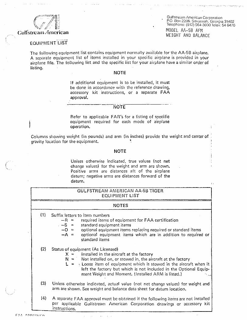
The following equipment list contains equipment normally available for the AA-5B airplane. A scpllrate equipment list of items installed in your specific airplane is provided in your airplane file. The following list and the specific list for your airplane have a similar order of listing.
NOTE
If additional equipment is to be installed, it must be done in accordance with the reference drawing, accessory kit instructions, or a separate FAA approval.
NOTE
Refer to applicable FAR's for a listing of specific equipment required for each mode of airplane operation.
Columns showing weight (in pounds) and arm (in inches) provide the weight and center of : gravity location for the equipment. ~ '
NOTE
Unless otherwise indicated, true values (not net change values) for the weight and arm are shown. Positive arms are distances aft of the airplane datum; negative arms are distances forward of the datum.
GULFSTREAM AMERICAN AA-5B TIGER EQUIPMENT LIST
NOTES
( 1) Suffix letters to item numbers -R = required items of equipment for FAA certification -S = standard equipment items -0 = optional equipment items replacing required or standard items -A = optional equipment items which are in addition to required or
standard items
(2) Status of equipment (As Licensed) X = Installed in the aircraft at the factory N = Not installed on, or stowed in, the aircraft at the factory L = ·. Loose item of equipment which is stowed in the aircraft when it
left the factory but which is not included in the Optional Equip-ment Weight and Moment. (Installed ARM is listed.) ·. -·
(3) Unless otherwise indicnted, actual value (not net change values) for weight and arm are shown. See weight and balance data sheet for datum location.
(4) A separate FAA approval must be obtained if the following items are not installed per applicable Gulfstream American Corporation drawings or accessory kit instructions.

Gulf stream. Aimcrican ITEM
NO. DESCRlf>TION
001-R Powerplant Installation includes Lycoming 180 HP engine, installation parts, fuel pump, vac pump drive, primer system, oil thermostatic bypass valve, alternator, carburetor air box, and filter
002-R Propeller installation including propeller, aluminum spacer and hardware
003-R Muffler assembly 004-R Oil Cooler and Lines 005-R Propeller Spinner 006-R Vacuum Pump Pad 007-R Quick Drain Oil Valve
(Exchangeable) 008-R Airspeed Indicator 009-R Altimeter (Standard)
~
010-R Magnetic Compass 011-R Instrument Cluster 012-R Pitot System (Std.) 013-0 Heated Pitot (Exchange) 014-R Recording Tachometer 015-R Stall Warning (Audible) 016-0 Altimeter, Sensitive (Feet
and Millibar) 017-0 Altimeter, Sensitive (Feet
and inches of Mercury) 018-A Gyro System (With Vacuum System) 019-A Outside Air Temp Indicator 020-A Turn Coordinator-Indicator 021-A Vertical Speed Indicator 022-R Alternator, 12V, 60A, (Included in
Engine Wt.) 023-R Battery, 12 volt, 25 amp-hour 024-R Light Cabin Dome 025-R Instrument Lights 026-R Navigation Lights 027-R Standard Wiring System 028-R Voltage Regulator-12 volt 029-R Aileron and Elevator Lock 030-R Brake, Toe Operated 031-R Electric Flaps 032-S Parking Brake 033-S Armrests Front and Rear (4) 034-S Ashtrays (2) 035-S Baggage Straps 036-S Cabin Air Ventilators 037-S Canopy Latch 038-S Center Console Fore and Aft 039-S Chart Holder 040-S Coat Hook
FAA APPROVED DATE 2/26/79 'Page 27
STATUS
Gulfstream American Corporation P.O. Box 2206. Savannah, Georgia 31402 Telephone: (912) 964-3000 Telex: 54 64 70 MODEL AA-5B AFM WEIGHT AND BALANCE
WT. LBS ARM INS
302.92 22.89
40.22 7.84 14.62 23.3 3.16 36.00 2.67 4.32
.01 37.00 0.00 0.00
.50· 68.50 1.12 68.00 .58 70.77 .48 69.25
1.78 122.65 .97 88.01 .62 69.00 .61 64.32
.88 68.00
.88 68.00 10.55 59.69
.38 69.20 2.40 66.56
.50 68.25
--- ---22.30 47.00
.37 124.00
.06 69.00
.95 111.70 1.36 41.30 .80 49.00 .08 71.00
2.80 54.43 9.56 124.40
.74 65.75
.88 109.65
.20 115.00
.30 150.00 2.28 66.03
.10 86.50 2.40 95.60 .08 70.00 .02 105.40
I 'fn•arn n~cr1.~an
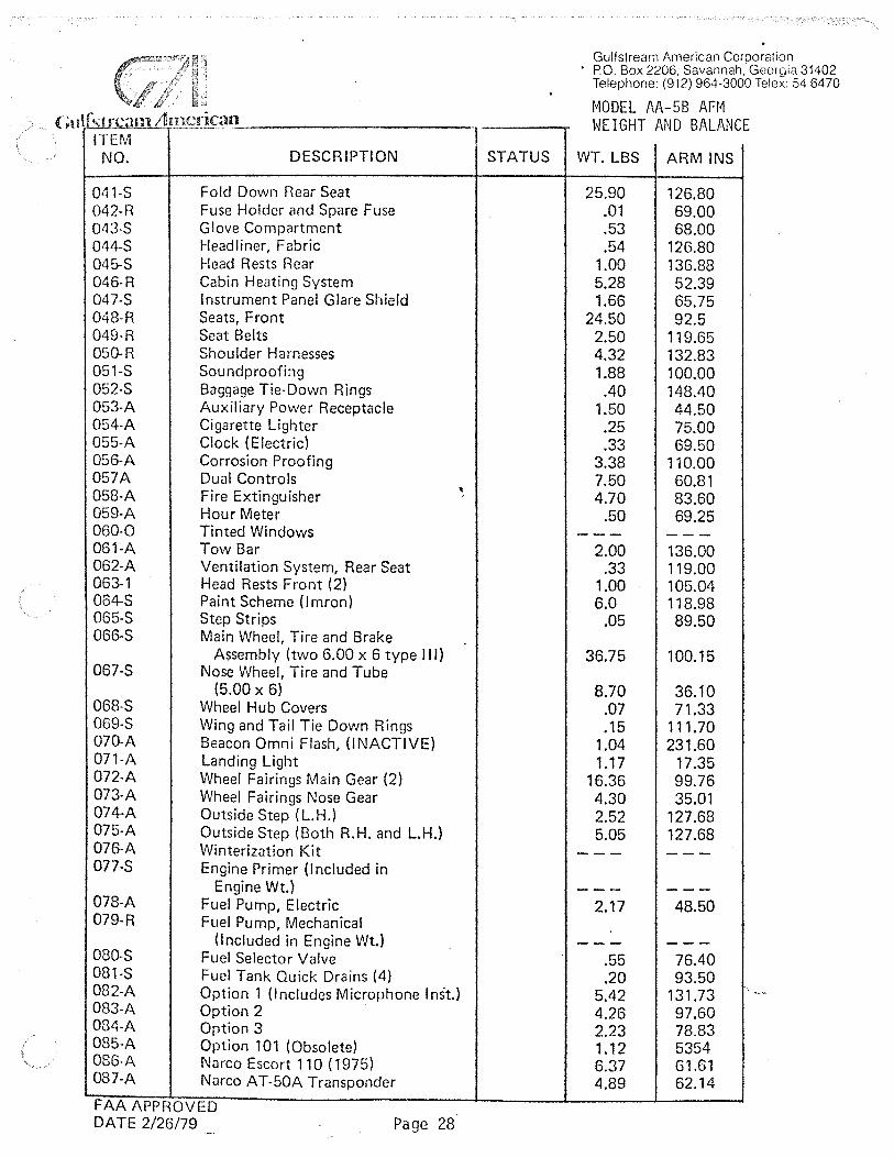
ITEM NO. DESCRIPTION
041-S Fold Down Rear Seat 042-R Fuse Holder and Spare Fuse 043-S Glove Compartment 044-S Headliner, Fabric 045-S Head Rests Rear 046-R Cabin Heating System 047-S Instrument Panel Glare Shield 048-R Seats, Front 049-R Seat Belts 050-R Shoulder Harnesses 051-S Soundproofing 052-S Baggage Tie-Down Rings 053-A Auxiliary Power Receptacle 054-A Cigarette Lighter 055-A Clock (Electric) 056-A Corrosion Proofing 057A Dual Controls 058-A Fire Extinguisher ' 059-A Hour Meter 060-0 Tinted Windows 061-A Tow Bar 062-A Ventilation System, Rear Seat 063-1 Head Rests Front (2) 064-S Paint Scheme (lmron) 065-S Step Strips 066-S Main Wheel, Tire and Brake
Assembly (two 6.00 x 6 type 111) 067-S Nose Wheel, Tire and Tube
(5.00 x 6) 068-S Wheel Hub Covers 069-S Wing and Tail Tie Down Rings 070-A Beacon Omni Flash, (INACTIVE) 071-A Landing Light 072-A Wheel Fairings Main Gear (2) 073-A Wheel Fairings Nose Gear 074-A Outside Step (l.H.) 075-A Outside Step (Both R.H. and L.H.) 076-A Winterization Kit 077-S Engine Primer (Included in
Engine Wt.} 078-A Fuel Pump, Electric 079-R Fuel Pump, Mechanical
(Included in Engine Wt.) 080-S Fuel Selector Valve 081-S Fuel Tank Quick Drains (4) 082-A Option 1 (Includes Microphone Inst.) 083-A Option 2 084-A Option 3 085-A Option 101 (Obsolete) 086-A Narco Escort 110 (1975) 087-A Narco AT-50A Transponder
FAA APPROVED DA TE 2/26/79 Page 28
T STATUS
Gulfstream American Corporation • PO. Box 2206. Savannah, Georgia 31402
Telephone: (912) 964-3000 Telex: 54 6470
MODEL AA-58 AFM WEIGHT AND BALANCE
WT. LBS ARM INS
25.90 126.80 .01 69.00 .53 68.00 .54 126.80
1.00 136.88 5.28 52.39 1.66 65.75
24.50 92.5 2.50 119.65 4.32 132.83 1.88 100.00 .40 148.40
1.50 44.50 .25 75.00 .33 69.50
3.38 110.00 7.50 60.81 4.70 83.60
.50 69.25 --- ---
2.00 136.00 .33 119.00
1.00 105.04 6.0 118.98
.05 89.50
36.75 100.15
8.70 36.10 .07 71.33 .15 111. 70
1.04 231.60 1.17 17.35
16.36 99.76 4.30 35.01 2.52 127.68 5.05 127.68
--- ------ ---
2.17 48.50
--- ---.55 76.40 .20 93.50
5.42 131.73 4.26 97.60 2.23 78.83 1.12 5354 6.37 61.61 4.89 62.14

,.., . ···---- -··~-,.-
. ITEM NO. DESCRIPTION
088-A Narco Com 1 OA/Nav 10 or Com 110/Nav 110
089-A Narco Com 11 A/Nav 11 or Com 111/Nav 111
090-A Narco Com 11 A/Nav 12/UG R 2A 091-A Narco Corn 11A/Nav 14/UGR
2A/DGO 10 092-A Narco ADF-31AB (1975) 093-A King XK 170B/Kl-201C 094-A King KX 1708/Kl-214 095-A Genave Delta 202 (1975) 096-A Genave Alpha 200A (1975) 097-A Genave Alpha 360/Theta 100 (1975) 098-A Genave Alpha 360/Theta 200/Phi
20 (1975} 099-A Emergency Locator Beacon
(C.C.C. Cl R-10) ( 1975} 100-A Narco Audio Switch Panel ( 1975) 101-A Narco M BT -12 Marker Beacon (less
Marker Beacon Light Assembly 102-A ... Marker Beacon Light Assembly 103-A Turn and Bank Installation 104-A Microphone Inst. 105-A Narco Mark 16 (1975) 106-A CP-125 Audio Panel 107-A PDF-35 Installation (1975) 108-A 2-Light Strobe Installation 109-A Century I Autopilot 110-A King KX-175/Kl-210C 111-A King KX-175/Kl-211 C or Kl-214 112-A King KT-78 113-A King KR-85/Kl-225 114-A King KMA-20 115-A King KT-76 116-A King System Inst. 117-A Pantronics H.F. OXIORA 118-A Bendix ADF 119-A Narco EL T-10 Emergency
Locator Beacon 120-A Narco ADF 140 Installation 121·A Sunvisor (2) 122-A Map Light 123-A Century 11 8 Autopilot 124-A DME-190 Narco 125-A Alternate Static Source 126-0 Encoding Altimeter (exchange)
AR-800 Narco or 8040-151< AeroMach or 5035P2-P25 United Inst. or 5035P-P22 United Inst.
127-0 True Air Speed Indicator (Exchange) ---- - ·- - - " - ·-
FAA APPROVED DATE 2/26/79 Page 29
'
STATUS
..
Gulfstream American Corporation P.O. Box 220G, Savannah, Geor~Jia 314'Telephone: {912) 964-3000 Telex: 54 6470 MODEL AA-58 AFM WEIGHT AND BALANCE
WT. LBS ARM INS
7.08 62.16
7.78 62.38 9.88 60.38
14.02 59.81 5.30 66.38
10.33 65.02 10.53 65.07 2.50 82.36 5.71 63.61 7.41 64.37
8.61 64.15
2.50 232.42 1.20 70.00
3.13 75.52 .13 69.00
1.94 68.00 .50 91.80
9.63 63.75 1.69 67.55 7.16 88.69 3.10 101.96 4.64 67.58
10.33 65.02 10.53 65.07 3.21 65.24 7.89 83.65 2.38 68.27 3.21 65.24
31.01 69.79 14.00 120.57 18.60 71.47
3.62 233.40 9.36 97.21 0.68 80.25 0.25 79.40
10.85 61.92 6.60 66.41 .22 68.50
1.08 66.98 .88 66.86 .88 66.86 .88 66.86
--- ---. -

"
< ,1 dhll c1m / imcric~m
ITEM NO.
128·0
129-A
130-A 131-A 132-A 133-1
134-A 135-A 136-A 137-A 138-A 139-A 140-A 141-A 142-A 143-A 144-A 145-A 146-A 147-A 148-A 149-A 150-A 151-A 152-A 153-A
154-A 155-A
156-A 157-A 158-R
r:AA APPROVED DA TE 2/26/79
DESCRIPTION
Narco EL T-1 OC Emergency Locator Beacon
Nose Gear Shock Absorber Installation (Includes Firewall Seal)
Glider Tow Hitch Installation Collins VHF-251 Collins VIR-351/IND-350/VHG-251 Collins VHF-251/VIR-351/
IN D-351 /G LS-350 Collins RCR-650/1 ND-650/ANT-650 Collins TD R-950/ Antenna Collins AM R-350/ Antenna Sidetone Intercom Narco COM-120 Narco Inst! NAV-121 Narco I nstl NA V-122 Narco Inst! AT-150 Narco ADF-141 '· Narco CP-135 King Kl-203 King Kl-204 King KN 75 MTG Tray Assy King Kl-208 King Kl-209 Collins VHF-250 Collins VI R-350 Collins VHG-250/VI R-350/IND-350 Collins VHF-250/VIR-350/
IN D-351 /G LS-350 Abrasion Boots, Horiz-Stabffizer Encoding Altimeter - United
Instruments 5035P2-P30 {Exchange)
Beacon OMNI Flash Storage Box Assembly Airplane Flight Manual
Page 30
STATUS
Gulfstream American Corporation P.O. Box 2206, Savannah, Georgia 31402 TC'.lephone: (912) 964-3000 Telex: 54 6470
MODEL AA-58 AFM WEIGHT AND BALANCE
I
WT. LBS ARM INS
2.70 233.40
4.31 46.55 6.42 223.51 4.40 62.32 9.02 63.02
I
11.46 61.37 6.60 103.81 I
2.27 67.11 2.80 67.78 ! 0.25 69.50 i
4.82 61.54 i 3.72 60.42 4.02 60.60 ' ~
4.32 61.05 i 6.20 98.74 i
I
2.10 67.51 I
1.60 67.30 '
1.70 67.30 i
1.60 66.20 ;
0.31 67.38 1.00 67.30 1.20 67.30 3.30 64.03 3.10 64.53 8.52 62.96
10.96 61.25 3.8 225.50
" 0.88 66.86 1.27 227.90 0.80 89.00 . ·Negligible
..