air/gas flow damper drive
TRANSCRIPT

®
AIR/GAS FLOW DAMPER DRIVE

G3 Damper Drive Modules
Key Industries Include:• Power Generation
• Petrochemical• Iron, Steel & Metals
• Cement• Paper & Pulp
• Sugar• Hospitals
HANDWHEEL - The handwheel isavailable in a range of diameters tosuit application torque requirementsand can be easily fitted to either sideof the gearbox without requiringadditional parts.
HANDWHEEL EXTENSION - When necessary a handwheelextension can be specified to ensure the handwheel is at safedistance from output lever to avoid risk of operator injury.
LEVER LOCKINGASSEMBLY - Providesinfinite angularadjustment of outputlever for ease ofinstallation.
OUTPUT LEVER - Dimensions are customerspecified to facilitate direct interchange whenKinetrol drive is replacing an existing drive. (PleaseNote: Safety measures such as guarding, shouldalways be in place to ensure that the moving levercannot cause injury to anyone within the vicinity).
ACTUATOR MOUNTINGPLATE-Allows actuator to be removed andrefitted without opening up gear
KINETROL VANE TYPEACTUATOR - Compactwith dual adjustable travelstops and one movingpart (no grinding gears orhysterisis) gives highefficiency & reliability.
InletDamper
IDFAN
OutletDamper
CHIMNEY
InletDamper FD
FANFD
FAN
OutletDamper
BOILER/HEATER
Opportunities to put theKinetrol Damper Drive to Work
• Crossover Dampers• Forced-Draft Fan Dampers• Induced-Draft Fan Dampers
• Fuel Nozzle Positioning Control• Gas-Recirculation Fan Dampers
• Hot Air Dampers• Primary-Air Dampers
• Secondary (Auxiliary) Air Dampers• Tertiary Air Dampers
• Tempering Air Dampers• Variable-Inlet Vane Dampers
• Cyclone Air• Pulverisor Air/Fuel Ratio• Flue Gas Recirculation
• Backdraft Damper• Baghouse Service
• Gas Turbine Intake & Exhaust• DesulphurisationLATCHING DE-CLUTCH LEVER - Engages
gears for manual operation or disengagesgears for pneumatic operation.
Replace floor standing drives with Kinetrol
BEFORE AFTER
An example of the layout in a ‘typical’ combustion system where Dampers are used for air flow control.
ROBUST HOUSING - Protects and seals criticalbearings that are greased for life. Unaffected by coaldust, fly ash and moisture etc.
OPTIONAL LIMIT SWITCH BOX -Gives remote indication of manualoverride status. May be used forinter lock safety system etc.
LIFTING EYE - Stronglifting eye for site handling.
G3 Drives are purpose designed solutions to air/gas flow control problems in new or existing burner, heater, boilerand turbine systems in power plants and a wide range of industrial applications.
The patented* G3 Damper Drive units set a new standard for control and durability. Combining the provenperformance and reliability of Kinetrol’s vane type actuator with an equally rugged integral manual override/mountingframe, the new damper drive is compact and unbeatable when it comes to control accuracy and cycle life.
Kinetrol’s vane type rotary pneumatic actuator eliminates the lost motion and wear associated with geared drivesand the conversion from linear to rotary motion. This results in a long maintenance-free life (reducing down time andmaintenance costs) and improved control (cutting fuel and production costs).
Compatible with all damper types, replacing existing floor mounted pneumatic, electric, hydraulic or electrohydraulicdrives could not be easier as Kinetrol’s G3’s are simple and quick to retrofit.
*Patent No: US 6,393, 931 B1
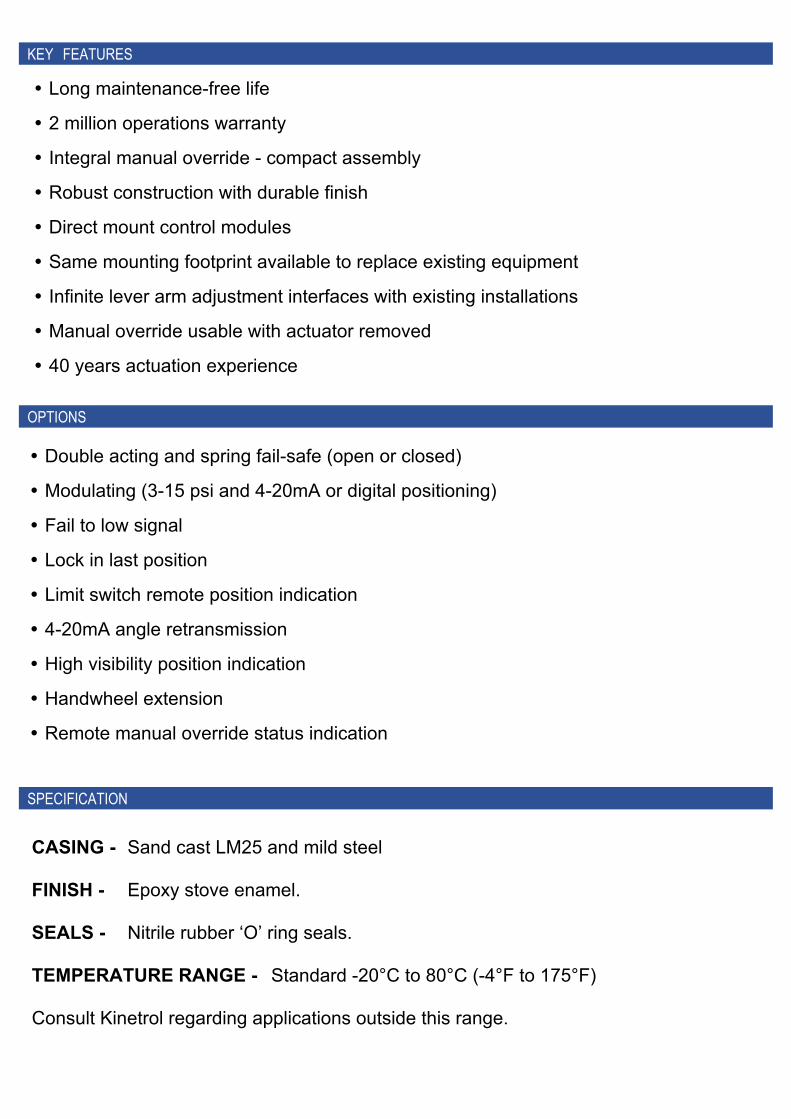
� Double acting and spring fail-safe (open or closed)
� Modulating (3-15 psi and 4-20mA or digital positioning)
� Fail to low signal
� Lock in last position
� Limit switch remote position indication
� 4-20mA angle retransmission
� High visibility position indication
� Handwheel extension
� Remote manual override status indication
KEY FEATURES
OPTIONS
SPECIFICATION
CASING - Sand cast LM25 and mild steel
FINISH - Epoxy stove enamel.
SEALS - Nitrile rubber ‘O’ ring seals.
TEMPERATURE RANGE - Standard -20°C to 80°C (-4°F to 175°F)
Consult Kinetrol regarding applications outside this range.
� Long maintenance-free life
� 2 million operations warranty
� Integral manual override - compact assembly
� Robust construction with durable finish
� Direct mount control modules
� Same mounting footprint available to replace existing equipment
� Infinite lever arm adjustment interfaces with existing installations
� Manual override usable with actuator removed
� 40 years actuation experience

K in e tro l L td, Tradin g E s tate , F arn h am , Su rre y GU9 9NU, E n g lan dTe le p h o n e : 0 1 2 5 2 7 3 3 8 3 8 F ax : 0 1 2 5 2 7 1 3 0 4 2
e -m ail: s ale s @k in e tro l.co mw w w .k in e tro l.co m Copyright 2020 Kinetrol Ltd KF-535 MAY/21
The policy of Kinetrol is one of continuous improvement. We reserve the right to alter the product as described and illustrated without notice.
Kinetrol is a registered trade mark
Ordering Codes
DP A
AdjustableEnd Stops
B
E
J
E
KM
N
RC3
C1C2
Alternative locationof handwheel &declutch lever
**
*
*
*
t
OF
GC
H
Model A B C D E* F* G H J K ØR M P Weight7 bar OUTPUTTORQUE (Nm)
124 366 294 336 275 205 300 300 165 216 152 21 25 70 46Kg 575144 410 380 390 275 300 300 300 165 216 152 21 25 70 46Kg 1375164 495 530 470 275 330 400 300 165 216 152 21 25 70 51Kg 3100184 721 680 620 496 430 760 479 229 416 222 27 38 94 141Kg 6900214 771 842 620 496 508 600 479 229 416 222 27 38 94 158Kg 12760
PRINCIPAL DIMENSIONS IN MM (Dimensions marked * are variables)
E* Table shows default dimensions, Longer offsets are available The weights listed above exclude the weight of the actuator, please see catalogue for actuator weights.
Model A B C D E* F* G H J K ØR M P Weight80psi OUTPUT
TORQUE (lbf.ins)127 14.4 11.6 13.2 10.8 11.0 12.0 12.0 6.5 8.5 6.0 0.83 1.0 2.8 102lb 5000147 16.2 15.0 15.4 10.8 12.0 12.0 12.0 6.5 8.5 6.0 0.83 1.0 2.8 102lb 9600167 19.5 20.9 18.5 10.8 13.0 16.0 12.0 6.5 8.5 6.0 0.83 1.0 2.8 112lb 21600187 28.4 26.8 24.4 19.5 17.0 30.0 18.9 9.0 16.38 8.74 1.05 1.6 3.7 310lb 48000217 30.4 33.2 24.4 19.5 20.0 24.0 18.9 9.0 16.38 8.74 1.05 1.6 3.7 350lb 89000
PRINCIPAL DIMENSIONS IN INCHES (Dimensions marked * are variables)
OPTIONAL LIMIT SWITCH BOX (TO INDICATE IFHANDWHEEL IS ENGAGED OR DISENGAGED)OPTIONS:0 = NO LIMIT SWITCH1 = 2 x i/S PROX. SENSORS2 = 2 x PNEUMATIC LS4 = 2 x V3 MECH LS5 = 2 x 20-260V ac PROX.*6 = 2 x 5-60V dc PROX.*7 = 4 x V3 MECH LS
HANDWHEEL SIDE(SEE SKETCH)
L=LEFTR=RIGHT
HOLE DIAMETER (d)2=12.7mm 1/2"3=15.9mm 5/8"A=11/16"4=19.1mm 3/4"5=22.2mm 7/8"6=25.4mm 1"7=28.6mm 1 1/8"8=31.8mm 1 1/4"9=38.1mm 1 1/2"
OUTPUT LEVERTHICKNESS (t)1=3/8"2=1/2"3=5/8"4=3/4"5=7/8"6=1"7=1 1/8"8=1 1/4"9=1 1/2"
D
IF NECESSARY, FIT OPTIONALEXTENSION TO ENSURE THAT
HANDWHEEL IS AT A SAFE DISTANCEFROM MOVING OUTPUT LEVER.
V = HIGH TEMP = STD
WHERE APPLICABLE:S = STANDARDY = NO COST OPTIONE = EXTRA COST OPTION
= NOT AVAILABLE
POSITION MONITOR ON LS BOX:C=YES0=NO
INCLUDING D/A ACTUATOR:
124
144
164
184
214
127
147
167
187
217
ISO D/A ACT (FOR USE WITHOR WITHOUT POSITIONER)=
ANSI D/A ACT (FOR USE WITHOR WITHOUT POSITIONER)=
HANDWHEELDIAMETER
(F) AVAILABLE ON MODELS:12 14 16 18 20
3=300mm 12" S S E4=400mm 16" E E S5=600mm 24" E E S6=762mm 30" S
HANDWHEELOFFSET
(E) AVAILABLE ON MODELS:12 14 16 18 21
1=300mm 12" S S2=330mm 13" S3=430mm 17" E E E S4=508mm 20" E E E E S5=600mm 24" E E E E E
LEVER HOLE PATTERN
DISTANCE FROM CENTRE AVAILABLE ON MODELS:No. C1 C2 C3 12 14 16 18 211 101.6mm 4" 152.4mm 6" 203.2mm 8" Y Y2 127mm 5" 152.4mm 6" 177.8mm 7" Y Y Y3 127mm 5" 198.1mm 7.8" 254mm 10" Y Y Y4 152.4mm 6" 254mm 10" 304.8mm 12" Y Y Y Y5 165.1mm 6.5" 190.5mm 7.5" 215.9mm 8.5" Y Y Y Y6 190.5mm 7.5" 215.9mm 8.5" 241.3mm 9.5" Y Y Y Y7 266.7mm 10.5" 292.1mm 11.5" 317.5mm 12.5" Y Y Y Y Y8 228.6mm 9" 342.9mm 13.5" 457.2mm 18" Y Y Y Y9 254mm 10" 304.8mm 12" 381mm 15" Y Y Y Y Y
10 254mm 10" 381mm 15" 508mm 20" Y Y Y Y Y11 254mm 10" 317.5mm 12.5" 406.4mm 16" Y Y Y Y Y12 254mm 10" 330.2mm 13" 406.4mm 16" Y Y Y Y Y13 304.8mm 12" 406.4mm 16" 444.5mm 17.5" Y Y Y Y Y14 317.5mm 12.5" 363.2mm 14.3" 406.4mm 16" Y Y Y Y Y15 147.3mm 5.8" 279.4mm 11" 304.8mm 12" Y Y Y Y16 152.4mm 6" 190.5mm 7.5" 228.6mm 9" Y Y Y17 101.6mm 4" 304.8mm 12" Y Y18 127mm 5" Y Y Y19 203.2mm 8" Y Y Y Y
* Not available with ATEX approval
DIMENSIONS
ORDERING CODES