aircraft wiring practices
TRANSCRIPT

Aircraft Wiring Practices
Job Aid 1.0 1
Federal AviationAdministration
AircraftWiringPractices(Job Aid)
This job aid covers applicable 14CFRs, policy, industry wiring practices; primary factors associated with wire degradation; information on TC/STC data package requirements; wire selection and protection; routing, splicing and termination practices; wiring maintenance concepts, including how to performa wiring general visual inspection. The job aid also includes numerous actual aircraft wiring photos and examples.
Aircraft Wiring Practices
Job Aid 1.0 2
Federal AviationAdministration 2Aircraft Wiring Practices Job Aid 1.0
Background
• Why the need for wiring practices training?
– Aging Systems Program
– Aging Transport Systems Rulemaking Advisory Committee (ATSRAC)
– Accident Service History
Historically, wiring was installed without much thought given tothe aging aspects:
• Fit and forget.
• Unanticipated failure modes and their severity.
- Arc tracking.
- Arcing.
- Insulation flashover.
Maintenance programs often did not address these aging aspects. Service history also indicates that Foreign Object Damage (FOD) such as drill shavings, caustic liquids, etc. does cause wiring degradation that can lead to wiring faults.
Aircraft Wiring Practices
Job Aid 1.0 3
Federal AviationAdministration 3Aircraft Wiring Practices Job Aid 1.0
Aging Systems Program
• Instituted a comprehensive aging non-structural systems program– Research to identify and prioritize opportunities to
enhance safety– A data-driven program based on
inspections and service history reviews– Multi-pronged solutions developed in conjunction with
aviation community– Modeled after successful aging structures program
Addresses a recommendation from the White House Commission on Aviation Safety to add non-structural systems to the aging aircraft program.
• FAA is using a data-driven approach to address safety concerns.
• Data are collected from research and development, various inspections, service history review and surveys of industry.
• Analysis of the data will result in revisions to maintenance programs, training programs and improved design solutions for wire bundle and component installations. The goal is to preclude accidents that may result from wire degradation.

Aircraft Wiring Practices
Job Aid 1.0 4
Federal AviationAdministration 4Aircraft Wiring Practices Job Aid 1.0
FAA Aging Transport Non-Structural Systems Plan• Air Transport Assoc. (ATA) study team:
– Using lessons learned from TWA 800 and Swissair 111
– Addressing recommendations from Gore Commission
– Collecting data from • On-site evaluations• Meetings with PMIs, Airbus, and Boeing• Analysis of aging systems using NASDAC
data bases
Following the TWA 800 accident, the FAA initiated investigations into fuel tank wiring. These investigations revealed a need for a comprehensive review of all systems wiring. Around this same time the White House Commission on Aviation Safety and Security, or informally known as the Gore Commission, recommended that the FAA, in cooperation with airlines and manufacturers, expand the FAA’s Aging Aircraft Program to cover non-structural systems. The ongoing Swissair 111 accident investigation has provided additional focus on wiring practices.
• As a first step towards addressing this recommendation, the FAA requested that ATA lead an effort to address aging non-structural systems. ATA responded by forming the Aging Systems Task Force (ASTF).
• To fully address the Gore Commission recommendation the FAA formed the Aging Non-Structural Systems Study team. This team made detailed on-site evaluations of three representative aging aircraft.
Based on the on-site evaluations, meetings with the Principal Maintenance Inspectors (PMIs), Airbus and Boeing, and analysis of aging systems using NASDAC data bases of service data, a plan was developed to address our aging transport airplane systems.

Aircraft Wiring Practices
Job Aid 1.0 5
Federal AviationAdministration 5Aircraft Wiring Practices Job Aid 1.0
FAA Aging Transport Non-Structural Systems Plan, cont.
• Study team, cont.
– Established ATSRAC to coordinate aging systems’ initiatives with the FAA
– Incorporated the Air Transport Association’s (ATA) aging system task force (ASTF) activities into ATSRAC
This plan called for the establishment of “an Aging Transport Systems Oversight Committee to coordinate the various aging systems initiatives within the FAA.” This task has been met with the formulation of the Aging Transport Systems Rulemaking Advisory Committee or also known as ATSRAC. ATSRAC is a formal advisory committee to the Administrator and holds public meetings every quarter.
ASTF has been incorporated into the ATSRAC tasking as a continuation of their original tasking plus additional tasking specific to ATSRAC.

Aircraft Wiring Practices
Job Aid 1.0 6
Aging Systems Program
ATSRACATSRAC•Fleet sampling inspections•Service data review•Working group outputs
FAAFAA•Study team inspections•Inspection support•Service data review•Research and development
ProductsProducts
Corrective actions
Inspection &maintenance practice
improvements
Improved design
practicesImproved
system data reporting
Improved training
This chart provides a conceptual look at the ATSRAC process and identifies multi-pronged solutions developed through a thorough review of the collected data. The products, as identified in the five bubbles at the bottom of the screen, are a result of data collection from a sampling of the fleet, review of service data, and ongoing research and development.
• These products could only be made through diligent efforts to collect data. From the start, the FAA has promoted a data-driven process that has provided the basis for addressing aging systems concerns.
• The primary use of these products will be to determine whether there are changes needed to design, manufacturing, inspection, maintenance, and modification processes for the wiring on transport airplanes to assure the continued safe operation of these airplanes.

Aircraft Wiring Practices
Job Aid 1.0 7
Federal AviationAdministration 7Aircraft Wiring Practices Job Aid 1.0
Aging Systems Program, cont.
• Aging systems research, engineering, and development (R,E,&D)– FAA R,E,&D
• Intrusive inspections• Arc fault circuit breaker development• Interconnect system testing and assessment• Inspection and testing technology development
The following programs are some of the R, E, & D programs currently in progress:
• Intrusive inspections
- Validated non-intrusive inspections and methods.
- Assess any physical degradation of wiring.
• Arc fault circuit breakers that involve:
- Development of a circuit interrupter that will remove power if an arcing event is detected.
- Direct replacement for existing circuit breakers.
• Broad area announcement for development of wire test and inspection systems.

Aircraft Wiring Practices
Job Aid 1.0 8
Federal AviationAdministration 8Aircraft Wiring Practices Job Aid 1.0
ATSRAC Findings
• Inspected 6 recently retired aircraft– 4 wire types– Intensive detailed visual inspection– Nondestructive testing (NDT)– Laboratory analysis
•• PurposePurpose: Determine the state of wire on aged aircraft
Selected wire installations on six recently decommissioned aircraft (having four broad category wire types) were subject to an intensive, detailed visual inspection, followed by nondestructive testing and laboratory analysis. Results of the detailed visualinspection, nondestructive testing, and laboratory analysis wereanalyzed to determine the state of wire on aged aircraft as a function of wire type and service history. In addition, the results of visual inspection were compared with the nondestructive testing and laboratory analysis to determine the efficacy of visual inspection for the detection of age-related deterioration.
Aircraft Wiring Practices
Job Aid 1.0 9
Federal AviationAdministration 9Aircraft Wiring Practices Job Aid 1.0
ATSRAC Findings, cont.
• ~1000 visual findings in the field– Mostly mis-installation or traumatic damage
• On-aircraft NDT/lab testing resulted in many additional findings– Non-negligible degradation on wire,
connectors, and terminals
Nearly one thousand conditions were observed in the field with visual inspection. On-aircraft non-destructive testing (NDT) and laboratory testing resulted in many additional findings on selected specimens. Most of the field-detected conditions could be classified as mis-installation or traumatic damage. There was, however, non-negligible degradation on wire, connectors, and terminals. The working group choose to focus on six important categories of wire degradation:
• Degraded wire repairs or splices,
• Heat damaged or burnt wire,
• Vibration damage or chafing,
• Cracked insulation,
• Arcing, and
• Insulation delamination.
Aircraft Wiring Practices
Job Aid 1.0 10
Federal AviationAdministration 10Aircraft Wiring Practices Job Aid 1.0
ATSRAC Findings, cont.
•• Results:Results: Visual inspection effective in identifying certain conditions (heat damaged/burnt wire and vibration damage or chafing)– Cannot be relied upon to find other conditions (cracked
insulation, arcing, insulation delamination, and degraded repairs or splices)
It was determined that visual inspection can be effective in identifying certain conditions (such as heat damage or burnt wire and vibration damage or chafing), but could probably not be relied upon to find other conditions (such as cracked insulation, arcing, insulation delamination, and degraded repairs or splices).
Aircraft Wiring Practices
Job Aid 1.0 11
Federal AviationAdministration 11Aircraft Wiring Practices Job Aid 1.0
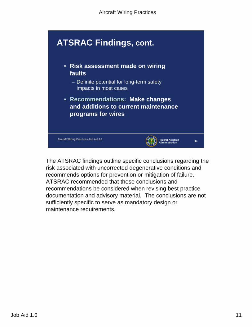
ATSRAC Findings, cont.
• Risk assessment made on wiring faults– Definite potential for long-term safety
impacts in most cases
•• Recommendations:Recommendations: Make changes and additions to current maintenance programs for wires
The ATSRAC findings outline specific conclusions regarding the risk associated with uncorrected degenerative conditions and recommends options for prevention or mitigation of failure. ATSRAC recommended that these conclusions and recommendations be considered when revising best practice documentation and advisory material. The conclusions are not sufficiently specific to serve as mandatory design or maintenance requirements.
Aircraft Wiring Practices
Job Aid 1.0 12
Federal AviationAdministration 12Aircraft Wiring Practices Job Aid 1.0
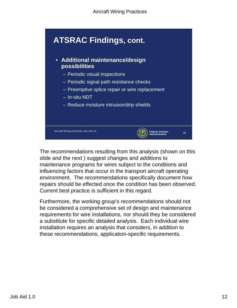
ATSRAC Findings, cont.
• Additional maintenance/design possibilities– Periodic visual inspections– Periodic signal path resistance checks– Preemptive splice repair or wire replacement– In-situ NDT– Reduce moisture intrusion/drip shields
The recommendations resulting from this analysis (shown on this slide and the next ) suggest changes and additions to maintenance programs for wires subject to the conditions and influencing factors that occur in the transport aircraft operating environment. The recommendations specifically document how repairs should be effected once the condition has been observed.Current best practice is sufficient in this regard.
Furthermore, the working group’s recommendations should not be considered a comprehensive set of design and maintenance requirements for wire installations, nor should they be considered a substitute for specific detailed analysis. Each individual wire installation requires an analysis that considers, in addition tothese recommendations, application-specific requirements.
Aircraft Wiring Practices
Job Aid 1.0 13
Federal AviationAdministration 13Aircraft Wiring Practices Job Aid 1.0
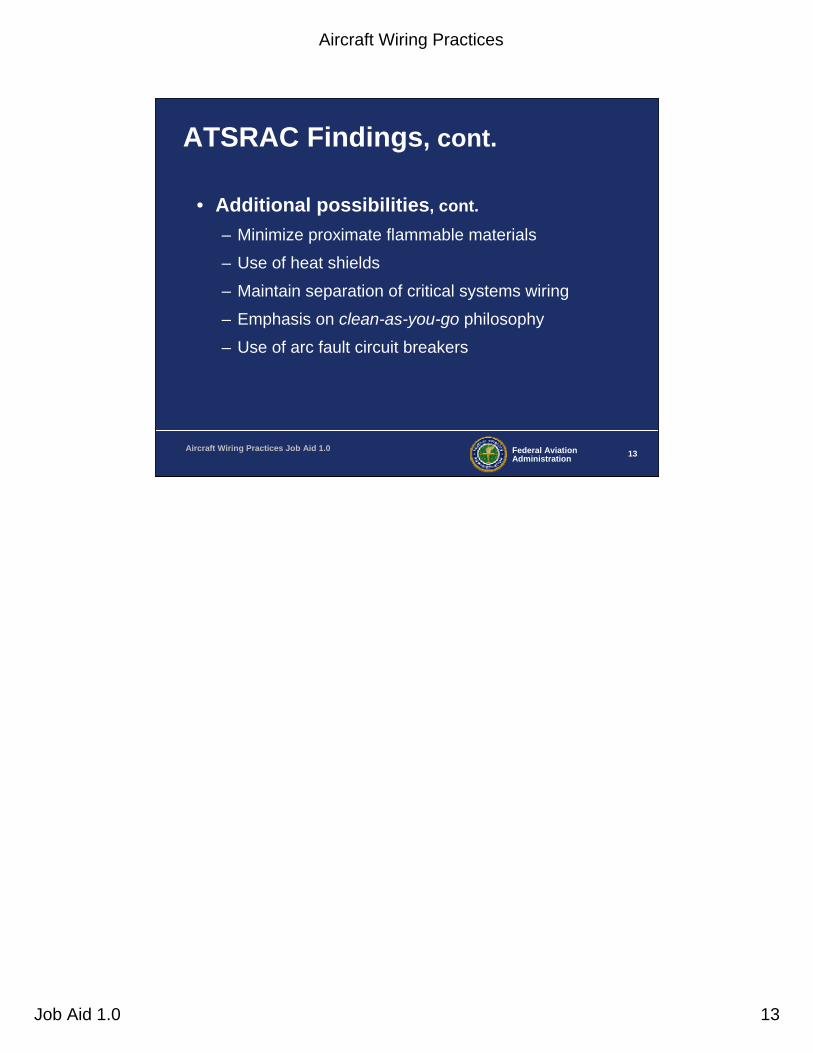
ATSRAC Findings, cont.
• Additional possibilities, cont.– Minimize proximate flammable materials
– Use of heat shields
– Maintain separation of critical systems wiring
– Emphasis on clean-as-you-go philosophy
– Use of arc fault circuit breakers

Aircraft Wiring Practices
Job Aid 1.0 14
Federal AviationAdministration 14Aircraft Wiring Practices Job Aid 1.0
TWA 800 Accident
• 7/17/1996, Boeing 747-131, broke up in flight and crashed in Atlantic near New York
• Ignition energy for center wing tank explosion most likely entered through fuel quantity indication system (FQIS) wiring
• Neither energy release mechanism or location of ignition determined
On July 17, 1996, about 8:30 p.m. eastern daylight time, TWA flight 800, a Boeing 747-131, broke up in flight and crashed in the Atlantic Ocean near East Moriches, New York. TWA flight 800 was operating under part 121 as a scheduled international passenger flight from John F. Kennedy International Airport (JFK), to Charles DeGaulle International Airport. The flight departed JFK at 8:19 p.m. All 230 people on board were killed and the airplane was destroyed.
• The ignition energy for the center wing tank explosion most likely entered the center wing tank through the fuel quantity indication system (FQIS) wiring and, although it is possible that the release of ignition energy inside the center wing tank was facilitated by the existence of silver-sulfide deposits on an FQIS component, neither the energy release mechanism nor the location of ignition inside the center wing tank could be determined from the available evidence.
• The Transport Airplane Directorate is currently in the rulemaking process to address certification aspects of fuel tank design with regard to minimizing the potential for fuel vapor ignition. As part of the rulemaking focus, wiring as a source of direct and indirect arcing is addressed.
Aircraft Wiring Practices
Job Aid 1.0 15
Federal AviationAdministration 15Aircraft Wiring Practices Job Aid 1.0
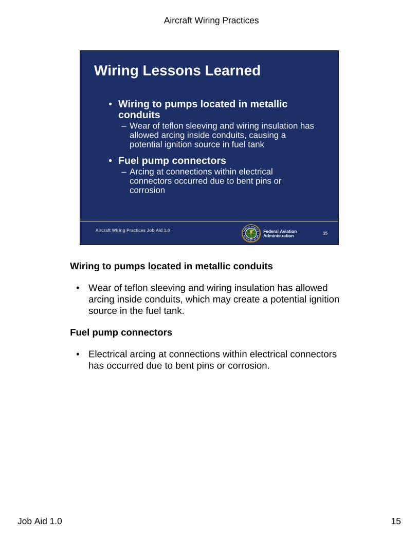
Wiring Lessons Learned
• Wiring to pumps located in metallic conduits– Wear of teflon sleeving and wiring insulation has
allowed arcing inside conduits, causing a potential ignition source in fuel tank
• Fuel pump connectors– Arcing at connections within electrical
connectors occurred due to bent pins or corrosion
Wiring to pumps located in metallic conduits
• Wear of teflon sleeving and wiring insulation has allowed arcing inside conduits, which may create a potential ignition source in the fuel tank.
Fuel pump connectors
• Electrical arcing at connections within electrical connectors has occurred due to bent pins or corrosion.

Aircraft Wiring Practices
Job Aid 1.0 16
Federal AviationAdministration 16Aircraft Wiring Practices Job Aid 1.0
Wiring Lessons Learned, cont.
• FQIS wiring– Wire bundles with degraded and corroded wires
mixed with high voltage wires
• FQIS probes– Corrosion caused reduced breakdown voltage
in FQIS wiring; fuel tank contamination led to reduced arc path between FQIS probe walls
FQIS wiring• Degradation of wire insulation (cracking) and corrosion
(copper sulfate deposits) at electrical connectors, unshielded FQIS wires have been routed in wire bundles with high voltage wires.
FQIS probes• Corrosion and copper sulfide deposits have caused reduced
breakdown voltage in FQIS wiring. FQIS wiring clamping features at electrical connections on fuel probes have caused damage to wiring and reduced breakdown voltage. Contamination in the fuel tanks (such as steel wool, lock wire, nuts, rivets, bolts; and mechanical impact damage) caused reduced arc path resistance between FQIS probe walls.

Aircraft Wiring Practices
Job Aid 1.0 17
Federal AviationAdministration 17Aircraft Wiring Practices Job Aid 1.0
Wiring Lessons Learned, cont.
• Bonding straps– Corrosion, inappropriately attached
connections
– Worn static bonds on fuel system plumbing
– Corroded bonding surfaces near fuel tank access panels
Bonding straps
• Corroded and inappropriately attached connections (including loose or improperly grounded attachment points).
• Static bonds on fuel system plumbing connections inside the fuel tank have been found worn due to mechanical wear of the plumbing from wing movement, and corrosion.
• Corrosion of bonding surfaces near fuel tank access panels has been reported that could diminish the effectiveness of bonding features and lead to arcing.
Aircraft Wiring Practices
Job Aid 1.0 18
Federal AviationAdministration 18Aircraft Wiring Practices Job Aid 1.0
Wiring Lessons Learned, cont.
• Electrostatic charge
– Use of non-conductive reticulated polyurethane foam allowed charge build up
– Fuel tank refueling nozzles caused increased fuel charging
Electrostatic charge• Use of non-conductive reticulated polyurethane foam allowed
charge build up and possible tank ignition. In another case the fuel tank refueling nozzles caused spraying of fuel into fuel tanks in such a manner that increased fuel charging, which also can lead to arcing inside the fuel tank.
Aircraft Wiring Practices
Job Aid 1.0 19
Federal AviationAdministration 19Aircraft Wiring Practices Job Aid 1.0
Swissair 111 Accident
• Crashed off coast of Nova Scotia on September 2, 1998
• Smoke in cockpit• Fire in cockpit overhead area• Metalized mylar insulation blankets• 23 wires found with arcing damage• Investigation ongoing
Swiss Air Flight Number 111, crashed on September 2, 1998. The aircraft, enroute from JF Kennedy, NY, to Geneva Switzerland, crashed in the ocean approximately 40 miles southwest Halifax Nova Scotia following a report of “smoke” in the cockpit. There were no survivors.
• By September 1999, the TSB had recovered approximately 98 percent of the aircraft by weight. The TSB elected to reconstruct the forward 10 meters of the MD-11 fuselage. Most of the aircraft pieces were about 6 to 12 inches in diameter and the components had to be molded and sewn together. The assembled fuselage presented a distinct footprint of fire damage in the overhead cockpit and overhead first class area.
• Investigation into a number of in-flight/ground fires on MD-11 and MD-80 series airplanes has revealed that insulation blankets covered with film material, also know as metalized mylar film material, may contribute to the spread of a fire when ignition occurs from small ignition sources such as electrical arcing and sparking.
• Twenty-three wires have been recovered with arcing damage. It can not be determined at this time if the arcing initiated the fire or whether the arcing was a result of the fire.
Aircraft Wiring Practices
Job Aid 1.0 20
Federal AviationAdministration 20Aircraft Wiring Practices Job Aid 1.0
Swissair 111 - FAA Plan of Action
• AVR-1 Directive (November 1998)– Minimize potential fuel sources
• Replace metalized mylar insulation blankets
– Minimize potential ignition sources• Focus on wiring
In November of 1988, the FAA formulated a plan of action to address issues related to the accident investigation. Since results from flammability testing at the FAA Tech Center indicated that the metalized mylar insulation blankets can spread a fire from an arcing incident (the original test method was determined to be insufficient and has been updated), the FAA developed a plan to replace all metalized mylar insulation blankets.
The FAA also determined that possible ignition sources should be minimized. This led to a comprehensive wiring corrective action plan to inspect and correct deficiencies.

Aircraft Wiring Practices
Job Aid 1.0 21
Federal AviationAdministration 21Aircraft Wiring Practices Job Aid 1.0
Maintenance
Age
Installation Environment
PhysicalProperties
Wiring Overview
Wire Wire DegradationDegradation
Wiring degradation• Wire degradation is a process that is a function of several variables; aging
is only one of these. Other main factors that influence wire degradation are the:
- Environment in which it is installed.- Physical properties of the wire.- Actual physical installation of the wire or wire bundle it self.- Maintenance (cleaning and repair) of the wires and wire bundles.
Characteristics of aging wiring• The manner in which wiring degrades is therefore dependent upon the
wire type, how it was originally installed, the overall time and environment exposed to in service, and how the wiring was maintained.
• Service history shows that “how the wiring is installed” has a direct effect on wire degradation. In other words, wiring that is not selected or installed properly has an increased potential to degrade at an accelerated rate. Therefore, good aircraft wiring practices are a fundamental requirement for wiring to remain safely intact.

Aircraft Wiring Practices
Job Aid 1.0 22
Federal AviationAdministration 22Aircraft Wiring Practices Job Aid 1.0
Causes of Wiring Degradation
• Vibration
• Moisture
• Maintenance
Vibration – High vibration areas tend to accelerate degradation over time, resulting in "chattering" contacts and intermittent symptoms. High vibration can also cause tie-wraps, or string-ties to damage insulation. In addition, high vibration will exacerbate any existing problem with wire insulation cracking. Moisture – High moisture areas generally accelerate corrosion of terminals, pins, sockets, and conductors. It should be noted that wiring installed in clean, dry areas with moderate temperatures appears to hold up well. Maintenance – Unscheduled maintenance activities, if done improperly, may contribute to long term problems and wiring degradation. Repairs that do not meet minimum airworthiness standards may have limited durability. Repairs that conform to manufacturers recommended maintenance practices are generally considered permanent and should not require rework if properly maintained.
• Metal shavings and debris have been discovered on wire bundles after maintenance or repairs have been conducted. Care should be taken to protect wire bundles and connectors during modification work, and to ensure all shavings and debris are cleaned up after work is completed.
• As a general rule, wiring that is undisturbed will have less degradation than wiring that is reworked. As wiring and components become more brittle with age, this effect becomes more pronounced.

Aircraft Wiring Practices
Job Aid 1.0 23
Federal AviationAdministration 23Aircraft Wiring Practices Job Aid 1.0
Causes of Wiring Degradation, cont.
• Indirect damage
• Chemical contamination
• Heat
• Installation
Indirect damage – Events such as pneumatic duct ruptures can cause damage that, while not initially evident, can later cause wiring problems. When such an event has occurred, surrounding wire should be carefully inspected to ensure no damage is evident.
Chemical contamination – Chemicals such as hydraulic fluid, battery electrolytes, fuel, corrosion inhibiting compounds, waste system chemicals, cleaning agents, deicing fluids, paint, and soft drinks can contribute to degradation of wiring. Wiring in the vicinity of these chemicals should be inspected for damage or degradation. Recommended original equipment manufacturer cleaning instructions should be followed.
• Hydraulic fluids, for example, require special consideration. Hydraulic fluid is very damaging to connector grommet and wire bundle clamps, leading to indirect damage, such as arcing and chafing. Wiring that may have been exposed to hydraulic fluid should be given special attention during wiring inspections.
Heat – Wiring exposed to high heat can accelerate degradation, insulation dryness, and cracking. Direct contact with a high heat source can quickly damage insulation. Even low levels of heat can degrade wiring over long periods of time. This type of degradation is sometimes seen on engines, in galleys, and behind lights.
Installation – Wiring not installed properly can further accelerate the wiring degradation process. Improper routing, clamping, and terminating during initial installation or during a modifications can lead to wiring damage.
Aircraft Wiring Practices
Job Aid 1.0 24
Federal AviationAdministration 24Aircraft Wiring Practices Job Aid 1.0
AC 43.13-1b AC 25-10
25.869
25.135325.1301/1309
Policy memo
25.1529
AC 25-16
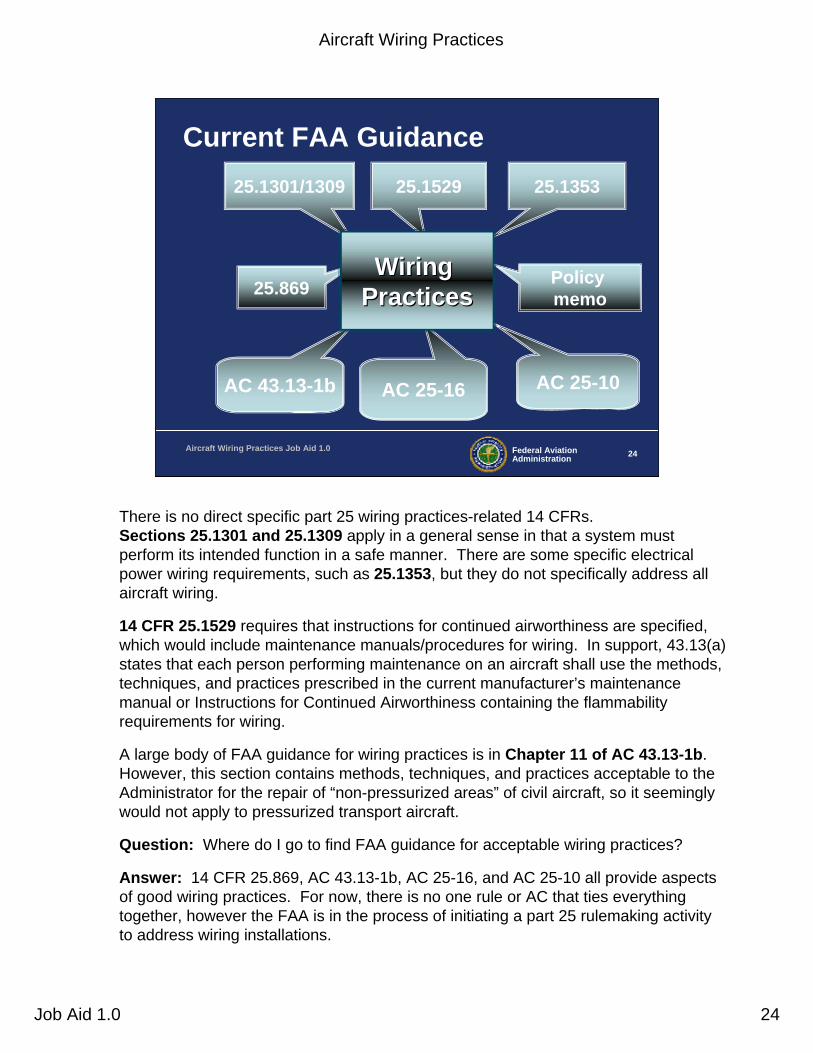
Current FAA Guidance
Wiring Wiring PracticesPractices
There is no direct specific part 25 wiring practices-related 14 CFRs. Sections 25.1301 and 25.1309 apply in a general sense in that a system must perform its intended function in a safe manner. There are some specific electrical power wiring requirements, such as 25.1353, but they do not specifically address all aircraft wiring.
14 CFR 25.1529 requires that instructions for continued airworthiness are specified, which would include maintenance manuals/procedures for wiring. In support, 43.13(a) states that each person performing maintenance on an aircraft shall use the methods, techniques, and practices prescribed in the current manufacturer’s maintenance manual or Instructions for Continued Airworthiness containing the flammability requirements for wiring.
A large body of FAA guidance for wiring practices is in Chapter 11 of AC 43.13-1b. However, this section contains methods, techniques, and practices acceptable to the Administrator for the repair of “non-pressurized areas” of civil aircraft, so it seemingly would not apply to pressurized transport aircraft.
Question: Where do I go to find FAA guidance for acceptable wiring practices?
Answer: 14 CFR 25.869, AC 43.13-1b, AC 25-16, and AC 25-10 all provide aspects of good wiring practices. For now, there is no one rule or AC that ties everything together, however the FAA is in the process of initiating a part 25 rulemaking activity to address wiring installations.

Aircraft Wiring Practices
Job Aid 1.0 25
Federal AviationAdministration 25Aircraft Wiring Practices Job Aid 1.0
Guidance: AC 43.13-1b
•• AC 43.13AC 43.13--1b:1b: Acceptable Methods, Techniques, and Practices -Aircraft Inspection and Repair
– Flight Standards AC
– Chapter 11- Aircraft Electrical Systems
AC 43.13-1b covers a fairly comprehensive wide range of basic wiring practices topics.

Aircraft Wiring Practices
Job Aid 1.0 26
Federal AviationAdministration 26Aircraft Wiring Practices Job Aid 1.0
Guidance: AC 25-16
•• AC 25 AC 25 --16:16: Electrical Fault and Fire Prevention and Protection (4/5/91)– Provides acceptable means to
address electrically caused faults, overheat, smoke, and fire in transport category airplanes
AC 25-16 provides wiring practices guidance as it relates to aircraft fire and smoke safety with emphasis on wiring flammability, circuit breaker protection, wiring near flammable fluids, and associated acceptable test methods.
This AC is currently being considered for updating.

Aircraft Wiring Practices
Job Aid 1.0 27
Federal AviationAdministration 27Aircraft Wiring Practices Job Aid 1.0
Guidance: AC 25-10
•• AC 25 AC 25 --10:10: Guidance for Installation of Miscellaneous, Non-required Electrical Equipment (3/6/87)– Provides acceptable means to
comply with applicable 14 CFRs associated with installation of electrical equipment such as galleys and passenger entertainment systems
AC 25-10 mainly covers non-required equipment installations such as galleys, passenger entertainment systems, etc. From a wiring standpoint, all systems should be treated equally, regardless of the functions criticality because of potential fire and smoke hazards.
This AC contains minimal wiring practices specifics, including general load analysis requirements and circuit breaker protection requirements, which are more thoroughly covered in AC 43.13-1b and AC 25-16, so we are not going to be covering 25-10 in any detail.

Aircraft Wiring Practices
Job Aid 1.0 28
Federal AviationAdministration 28Aircraft Wiring Practices Job Aid 1.0
Electrical Load Determination
• Load analysis– Ensure that total electrical load can be safely
controlled or managed within rated limits of affected components of aircraft’s electrical system (25.1351)
– New or additional electrical devices should not be installed without an electrical load analysis (AC 43.13-1b)
Electrical load determination is to ensure each aircraft electrical bus can safely support a predetermined amount of electrical loadthat is based on the electrical capacity of the aircraft generators and the aircraft’s overall electrical distribution system.
25.1351 requirement: It must be determined through analysis that all electrical devices can be safely controlled or managed by the aircraft’s electrical system.
AC 43.13-1b: Whenever an electrical device is added, a load analysis should be performed to ensure that the new load on the bus can be powered adequately such that there is adequate electrical power margin to avoid overloading the bus.
Where necessary as determined by a load analysis, wire, wire bundles, and circuit protective devices having the correct ratings should be added or replaced.
Aircraft Wiring Practices
Job Aid 1.0 29
Federal AviationAdministration 29Aircraft Wiring Practices Job Aid 1.0
Circuit Breaker Devices
• Must be sized to open before current rating of attached wire is exceeded, or before cumulative rating of all connected loads are exceeded, whichever is lowest (25.1357)
Section 25.1357 requires that automatic protective devices be used to minimize distress to the electrical system and minimize hazard to the airplane in the event of wiring faults or serious malfunction of the system or connected equipment.
Aircraft Wiring Practices
Job Aid 1.0 30
Federal AviationAdministration 30Aircraft Wiring Practices Job Aid 1.0
Circuit Breaker Protection
• “A circuit breaker must always open before any component downstream can overheat and generate smoke or fire.” (AC 43.13-1b, para. 11-48)
• “Circuit breakers are designed as circuit protection for the wire, not for protection of black boxes or components . . .” (AC 43.13-1b, para. 11-51)
AC 43.13-1b contains some conflicting statements. The bullets in this slide are somewhat contradictory. The first bullet says that the breaker must protect against any downstream component failure. The second bullet says breakers are designed such that they DO NOT protect components or LRUs.
In reality, breakers are sized to protect the aircraft wiring as the main design constraint. Any further protection of components or LRUs is desirable but not mandatory.
Ideally, circuit breakers should protect against any wiring fault that leads to arcing, sparking, flames, or smoke. But as we will learn, thermal circuit breakers do not always detect arcing events.
Aircraft Wiring Practices
Job Aid 1.0 31
Federal AviationAdministration 31Aircraft Wiring Practices Job Aid 1.0
Circuit Breaker Protection, cont.
• Use of a circuit breaker as a switch is not recommended– Repeated opening and closing of
contacts can lead to damage and premature failure of circuit breakers
– Most circuit breaker failures are latent
Most circuit breakers, other than some remote control circuit breakers (RCCB), are not designed as switches and should not be used as a switch. Repeated opening and closing of the contacts can lead to damage and premature failure of the circuitbreakers. Also keep in mind that circuit breaker failures are, for the most part, latent in nature. So you won’t know they have failed until you need them.
Aircraft Wiring Practices
Job Aid 1.0 32
Federal AviationAdministration 32Aircraft Wiring Practices Job Aid 1.0
Wire Selection
• Size wires so they:– Have sufficient mechanical strength
– Do not exceed allowable voltage drop levels
– Are protected by circuit protection devices
– Meet circuit current-carrying requirements
Section 25.1357 requires that automatic protective devices be used to minimize distress to the electrical system and minimize hazard to the airplane in the event of wiring faults or serious malfunction of the system or connected equipment.

Aircraft Wiring Practices
Job Aid 1.0 33
Federal AviationAdministration 33Aircraft Wiring Practices Job Aid 1.0
Wire Selection, cont.
• Mechanical strength of wire sizes less than #20– Do not use wire with less than 19 strands– Provide additional support at terminations– Should not be used when subject to excessive
vibration, repeated bending, or frequent disconnection
(ref. para. 11-66(a), page 11-21)
Wire containing less than 19 conductor strands must not be used.Consideration should be given to the use of high-strength alloy conductors in small gauge wires to increase mechanical strength.As a general practice, wires smaller than #20 should be provided with additional clamps and be grouped with at least three other wires. They also should have additional support at terminations, such as connector grommets, strain relief clamps, shrinkable sleeving, or telescoping bushings. They should not be used in applications where they will be subjected to excessive vibration, repeated bending, or frequent disconnection from screw termination.

Aircraft Wiring Practices
Job Aid 1.0 34
Federal AviationAdministration 34Aircraft Wiring Practices Job Aid 1.0
Determining Current-Carrying Capacity
• Effect of heat on wire insulation– Maximum operating temperature
– Single wire or wires in a harness
– Altitude
Heating is an important factor affecting wire insulation. This must be factored into proper selection of wire for each particular application.
Aircraft Wiring Practices
Job Aid 1.0 35
Federal AviationAdministration 35Aircraft Wiring Practices Job Aid 1.0
Determining Wire System Design
•• AC 43.13AC 43.13--1b, Section 5:1b, Section 5: tables and figures provide an acceptable method of determining wire system design
The applicant should ensure that the maximum ambient temperature that the wire bundles will be subjected to, plus thetemperature rise due to the wire current loads, does not exceed the maximum conductor temperature rating.
In smaller harnesses, the allowable percentage of total current may be increased as the harness approaches the single wire configuration.
The continuous current ratings contained in the tables and figures in AC 43.13-1b were derived only for wire application, and cannot be applied directly to associated wire termination devices (e.g., connector contacts, relays, circuit breakers, switches). The current ratings for devices are limited by the design characteristics of the device. Care should be taken to ensure that the continuous current value chosen for a particular system circuit shall not create hot spots within any circuit element which could lead to premature failure.

Aircraft Wiring Practices
Job Aid 1.0 36
Federal AviationAdministration 36Aircraft Wiring Practices Job Aid 1.0
Wire Selection
• Conductor stranding– Minimizes fatigue breakage
• Platings for all copper aircraft wiring– Plated because bare copper develops
surface oxide film — a poor conductor• Tin < 150° C• Silver < 200° C• Nickel < 260° C
Elevated temperature degradation of tin- and silver-plated copper conductors will occur if they are exposed to continuous operation at elevated levels.
• For tin-plated conductors, tin-copper intermetallics will form, resulting in an increase in conductor resistance.
• For silver-plated conductors, degradation in the form of interstrand bonding, silver migration, and oxidation of the copper strands will occur with continuous operation near rated temperature, resulting in loss of wire flexibility. Also,due to potential fire hazard, silver-plated conductors shall not be used in areas where they are subject to contamination by ethylene glycol solutions.
• Both tin- and silver-plated copper conductors will exhibit degraded solderability after exposure to continuous elevated temperature.

Aircraft Wiring Practices
Job Aid 1.0 37
Federal AviationAdministration 37Aircraft Wiring Practices Job Aid 1.0
Wire Substitution for Repairs and Maintenance
• When replacement wire is required, review aircraft maintenance manual to determine if original aircraft manufacturer (OAM) has approved any substitution – If not approved, then contact OAM
for an acceptable replacement
Most aircraft wire designs are to specifications that require manufacturers to pass rigorous testing of wires before they are approved or added to a Qualified Products List. Aircraft manufacturers who maintain their own wire specifications exercise close control of their approved sources. Therefore, it is important to review the aircraft maintenance manual or contact the original aircraft manufacturer (OAM) when wire substitutionsare necessary.
The OAM may have special concerns regarding shielding, insulation, etc. for certain wiring on the aircraft that perform critical functions or wiring that is chosen based on a set of unique circumstances.

Aircraft Wiring Practices
Job Aid 1.0 38
Federal AviationAdministration 38Aircraft Wiring Practices Job Aid 1.0
Wiring Routing
• Eliminate potential for chafing against structure or other components
• Position to eliminate/minimize use as handhold or support
• Minimize exposure to damage by maintenance crews or shifting cargo
• Avoid battery electrolytes or other corrosive fluids
In general, wiring should be routed in such a manner to ensure reliability and to offer protection from the potential hazards shown in this slide.
The next several slides are pictures illustrating the hazards listed in this current slide.

Aircraft Wiring Practices
Job Aid 1.0 39
Wire Riding on Structure
Power cables riding on structure can
cause damage to the power cables
Improper
Proper
Example of wire chafing.
Aircraft Wiring Practices
Job Aid 1.0 40
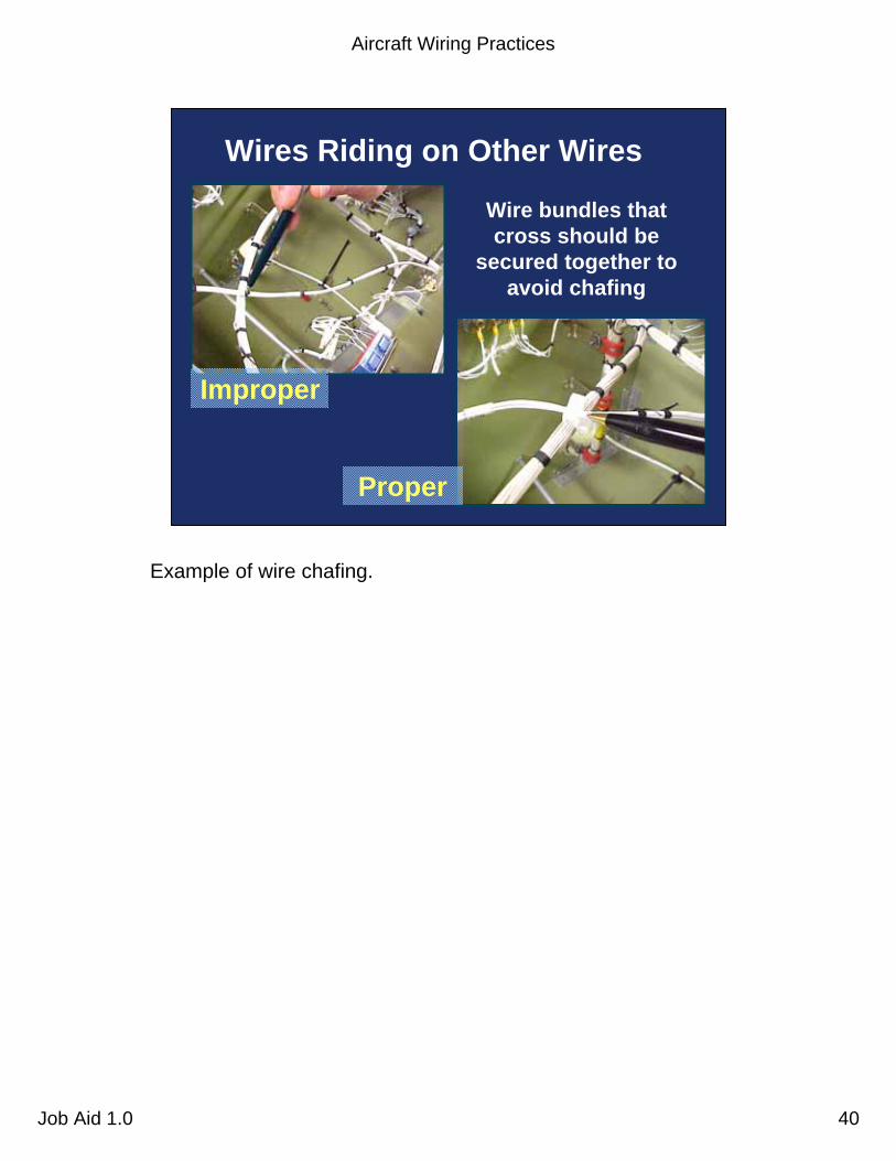
Wires Riding on Other Wires
Wire bundles that cross should be
secured together to avoid chafing
Improper
Proper
Example of wire chafing.

Aircraft Wiring Practices
Job Aid 1.0 41
Wires Riding on Lightening Hole
If the grommet is too short, then there is wire bundle chafing
Improper
Proper
Example of wire chafing.
Aircraft Wiring Practices
Job Aid 1.0 42
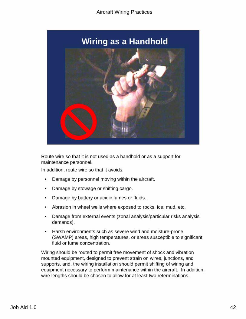
Wiring as a Handhold
Route wire so that it is not used as a handhold or as a support for maintenance personnel.In addition, route wire so that it avoids:
• Damage by personnel moving within the aircraft.
• Damage by stowage or shifting cargo.
• Damage by battery or acidic fumes or fluids.
• Abrasion in wheel wells where exposed to rocks, ice, mud, etc.
• Damage from external events (zonal analysis/particular risks analysis demands).
• Harsh environments such as severe wind and moisture-prone (SWAMP) areas, high temperatures, or areas susceptible to significant fluid or fume concentration.
Wiring should be routed to permit free movement of shock and vibration mounted equipment, designed to prevent strain on wires, junctions, and supports, and, the wiring installation should permit shifting of wiring and equipment necessary to perform maintenance within the aircraft. In addition, wire lengths should be chosen to allow for at least two reterminations.

Aircraft Wiring Practices
Job Aid 1.0 43
Federal AviationAdministration 43Aircraft Wiring Practices Job Aid 1.0
Wiring Routing, cont.
• Protect wires in wheel wells and other exposed areas
• Route wires above fluid lines, if practicable
• Use drip loops to control fluids or condensed moisture
• Keep slack to allow maintenance and prevent mechanical strain
Ensure that wires and cables are adequately protected in wheel wells and other areas where they may be exposed to damage from impact of rocks, ice, mud, etc. (If re-routing of wires or cables is not practicable, protective jacketing may be installed.) This type of installation must be held to a minimum.
Where practical, route wires and cables above fluid lines. Wires and cables routed within 6 inches of any flammable liquid, fuel, or oxygen line should be closely clamped and rigidly supported. A minimum of 2 inches must be maintained between wiring and such lines or related equipment, except when the wiring is positively clamped to maintain at least 1/2-inch separation or when it must be connected directly to the fluid-carrying equipment.
Ensure that a trap or drip loop is provided to prevent fluids or condensed moisture from running into wires and cables dressed downward to a connector, terminal block, panel, or junction box.
Wires and cables installed in bilges and other locations where fluids may be trapped are routed as far from the lowest point as possible or otherwise provided with a moisture-proof covering.

Aircraft Wiring Practices
Job Aid 1.0 44
Path of exposed end
Broken wire shall not make contact with fluid line
Wire Bundles Above Fluid Lines
Wire bundles above fluid lines. The clamps should be a compression type and should be spaced so that, assuming a wire break, the broken wire will not contact hydraulic lines, oxygen lines, pneumatic lines, or other equipment whose subsequent failure caused by arcing could cause further damage.

Aircraft Wiring Practices
Job Aid 1.0 45
Wires improperly tied, riding on hydraulic lines,
contaminated with caustic fluid
This example shows a number of problems:
• Wires in the bundles are not tied properly.
• The wire bundle is riding hard on the hydraulic lines.
• The wire bundles appears to be contaminated with hydraulic fluid residue.

Aircraft Wiring Practices
Job Aid 1.0 46
Wire bundle breakout
Figure 8 loop may be located before or after tail of Y
Plastic mechanical strapping
Wire bundles
Before
After
Y Type Wire Bundle Breakouts
Head of strap shall not be located in this area or touching anything to cause chafing
Wire bundle breakouts. There are three basic wire bundle breakout types used in routing aircraft wiring. They are called the “Y,” “T,” and Complex types.
The “Y” type of breakout is used when a portion of wiring from one direction of the wire bundle departs the bundle to be routed in another direction.
• Care should be taken when plastic tie wraps are used to provide wire containment at the breakout so that the tie wrap head does not cause chafing damage to the wire bundle at the breakout junction.

Aircraft Wiring Practices
Job Aid 1.0 47
Plastic mechanical strapping
Wire bundle breakout
Wire bundle
Head of strap shall not be located in
this area or touching anything
to cause chafing
T Type Wire Bundle Breakouts
The “T” type of breakout (also called 90° breakout) is used when portions of wiring from both directions in the wire bundle depart the bundle to be routed in another direction.
Aircraft Wiring Practices
Job Aid 1.0 48
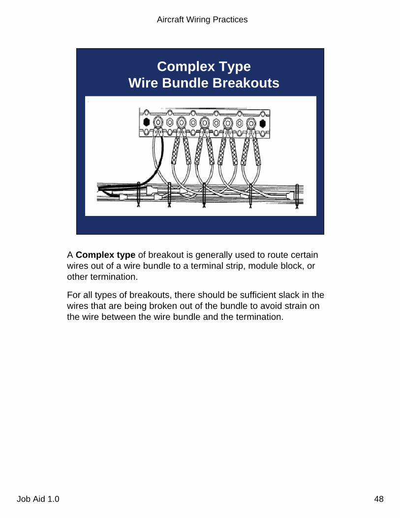
Complex TypeWire Bundle Breakouts
A Complex type of breakout is generally used to route certain wires out of a wire bundle to a terminal strip, module block, orother termination.
For all types of breakouts, there should be sufficient slack in the wires that are being broken out of the bundle to avoid strain onthe wire between the wire bundle and the termination.

Aircraft Wiring Practices
Job Aid 1.0 49
Federal AviationAdministration 49Aircraft Wiring Practices Job Aid 1.0
Stand-offs
• Use stand-offs to maintain clearance between wires and structure– Employing tape or tubing is generally notnot
acceptable as an alternative
•• Exception:Exception: Where impossible to install off-angle clamps to maintain wiring separation in holes, bulkheads, floors, etc.
The wiring design should preclude wire bundles from contacting structure. Stand-offs should be used to maintain clearance between wires and structure.
Employing tape or protective tubing as an alternative to stand-offs should be avoided as a primary means of preventing wire bundle contact with structure.
Exception: Using tape or tubing is allowed in cases where it is impossible to install off-angle clamps to maintain wire separation in holes, bulkheads, floors, etc.

Aircraft Wiring Practices
Job Aid 1.0 50
Using Stand-offs
Improper
Proper
Aircraft Wiring Practices
Job Aid 1.0 51
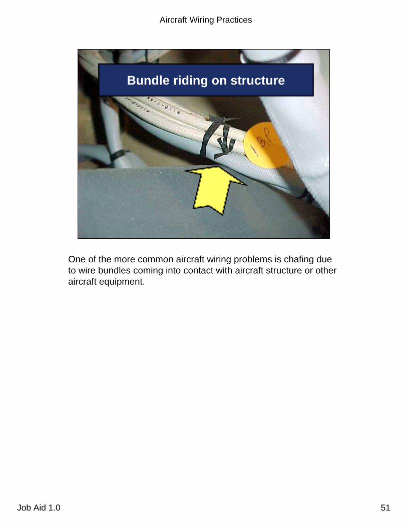
Bundle riding on structure
One of the more common aircraft wiring problems is chafing due to wire bundles coming into contact with aircraft structure or other aircraft equipment.

Aircraft Wiring Practices
Job Aid 1.0 52
Wire bundle riding on control cable
This picture shows a wire bundle that is in close contact with acontrol cable. Adequate distance between wire bundles and control cables should be maintained to account for movement due to slack and maintenance.
Aircraft Wiring Practices
Job Aid 1.0 53
Federal AviationAdministration 53Aircraft Wiring Practices Job Aid 1.0
Clamping
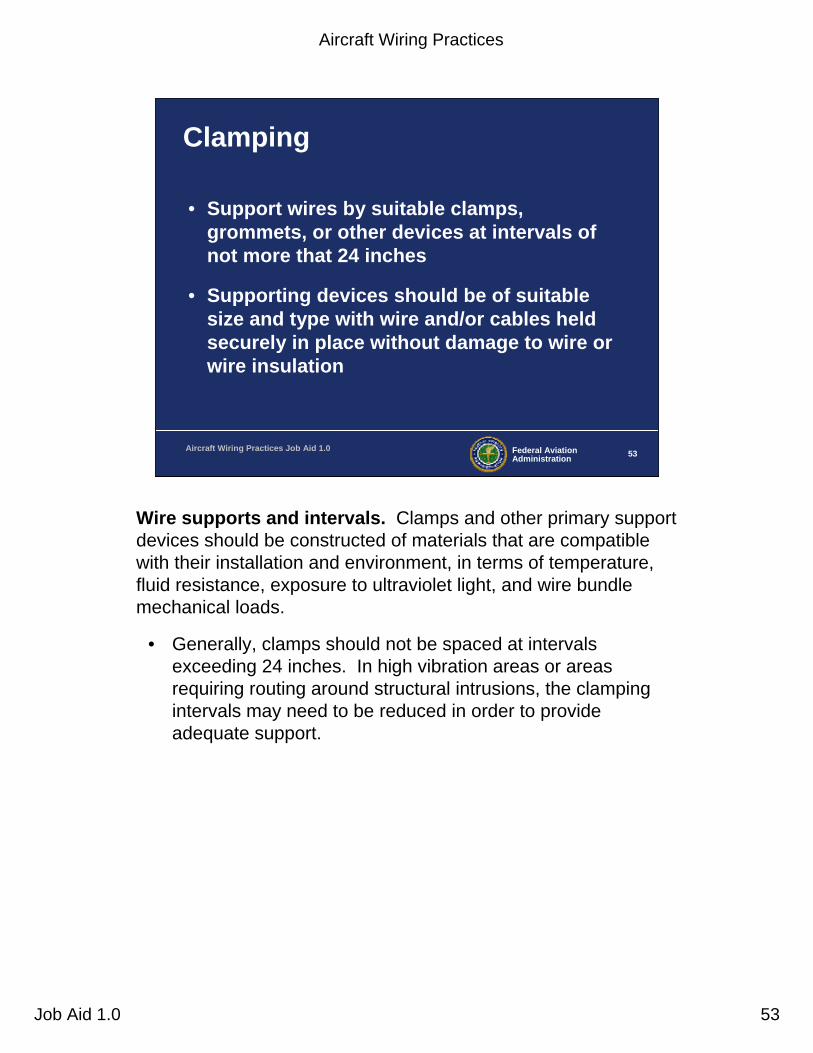
• Support wires by suitable clamps, grommets, or other devices at intervals of not more that 24 inches
• Supporting devices should be of suitable size and type with wire and/or cables held securely in place without damage to wire or wire insulation
Wire supports and intervals. Clamps and other primary support devices should be constructed of materials that are compatible with their installation and environment, in terms of temperature, fluid resistance, exposure to ultraviolet light, and wire bundlemechanical loads.
• Generally, clamps should not be spaced at intervals exceeding 24 inches. In high vibration areas or areas requiring routing around structural intrusions, the clamping intervals may need to be reduced in order to provide adequate support.
Aircraft Wiring Practices
Job Aid 1.0 54
Federal AviationAdministration 54Aircraft Wiring Practices Job Aid 1.0
Clamps
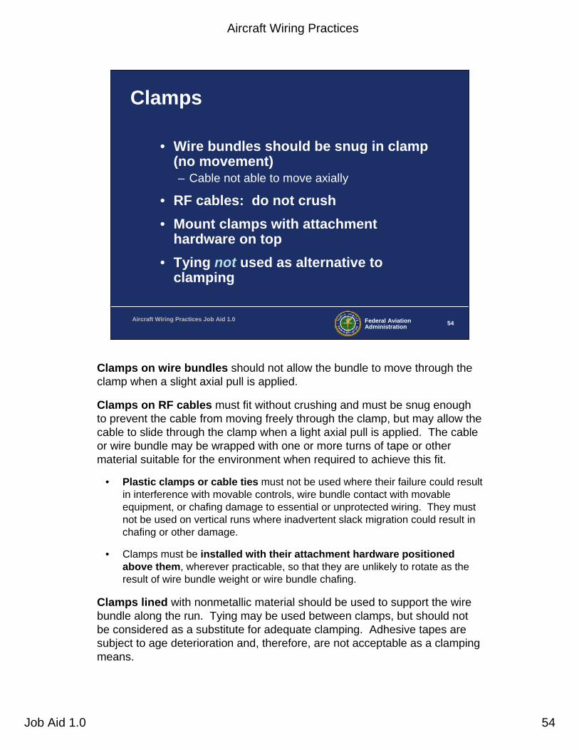
• Wire bundles should be snug in clamp (no movement) – Cable not able to move axially
• RF cables: do not crush• Mount clamps with attachment
hardware on top• Tying not used as alternative to
clamping
Clamps on wire bundles should not allow the bundle to move through the clamp when a slight axial pull is applied.
Clamps on RF cables must fit without crushing and must be snug enough to prevent the cable from moving freely through the clamp, but may allow the cable to slide through the clamp when a light axial pull is applied. The cable or wire bundle may be wrapped with one or more turns of tape or other material suitable for the environment when required to achieve this fit.
• Plastic clamps or cable ties must not be used where their failure could result in interference with movable controls, wire bundle contact with movable equipment, or chafing damage to essential or unprotected wiring. They must not be used on vertical runs where inadvertent slack migration could result in chafing or other damage.
• Clamps must be installed with their attachment hardware positioned above them, wherever practicable, so that they are unlikely to rotate as the result of wire bundle weight or wire bundle chafing.
Clamps lined with nonmetallic material should be used to support the wire bundle along the run. Tying may be used between clamps, but should not be considered as a substitute for adequate clamping. Adhesive tapes are subject to age deterioration and, therefore, are not acceptable as a clamping means.

Aircraft Wiring Practices
Job Aid 1.0 55
Example of Correct Cable Slack
Appropriate slack
This is an example of an appropriate amount of cable slack between clamps. Appropriate slack protects the wires from stress and from contact with inappropriate surfaces.
• Too much cable slack can allow the cable to contact structure or other equipment which could damage the wire bundle.
• Too little slack can cause a pre-load condition on the cable which could cause damage to the wire bundle and/or clamps as well.
• Also, sufficient slack should be left between the last clamp and the termination or electrical equipment to prevent strain at the terminal and to minimize adverse effects of shock-mounted equipment.
Aircraft Wiring Practices
Job Aid 1.0 56
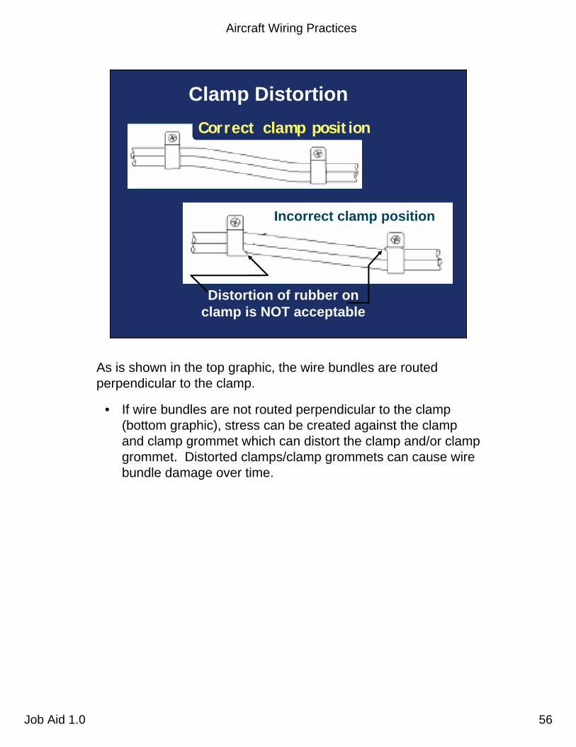
Clamp Distortion
Incorrect clamp position
Distortion of rubber on clamp is NOT acceptable
Correct clamp position
As is shown in the top graphic, the wire bundles are routed perpendicular to the clamp.
• If wire bundles are not routed perpendicular to the clamp (bottom graphic), stress can be created against the clamp and clamp grommet which can distort the clamp and/or clamp grommet. Distorted clamps/clamp grommets can cause wire bundle damage over time.
Aircraft Wiring Practices
Job Aid 1.0 57
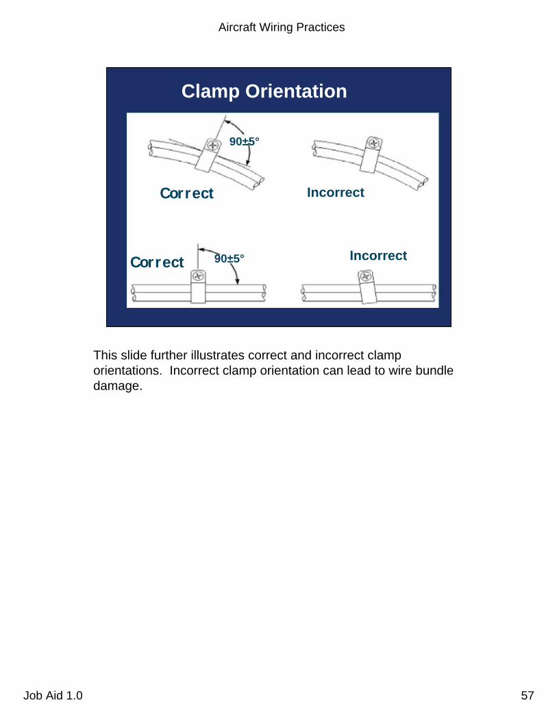
Correct
Correct Incorrect
Incorrect
90±5°
Clamp Orientation
90±5°
This slide further illustrates correct and incorrect clamp orientations. Incorrect clamp orientation can lead to wire bundle damage.

Aircraft Wiring Practices
Job Aid 1.0 58
Example - Clamp Distortion
This photograph is a good example of clamp distortion. Note that the wire bundle is not perpendicular to the clamp.
Aircraft Wiring Practices
Job Aid 1.0 59
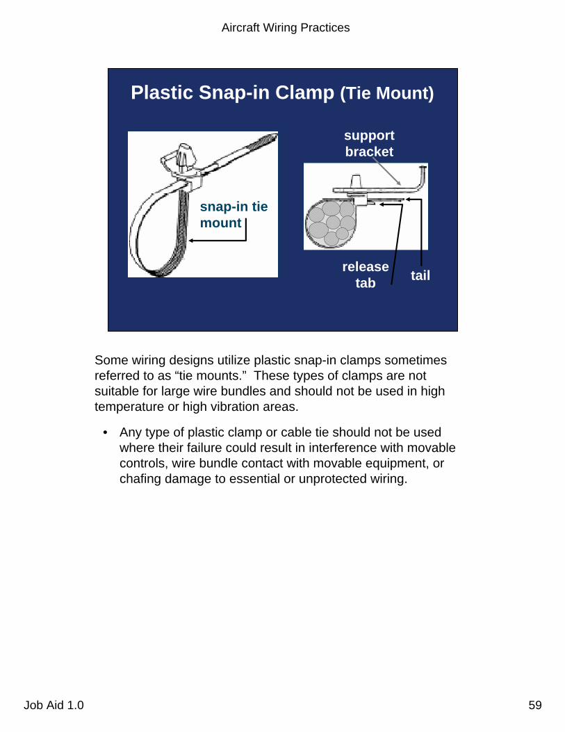
release tab
support bracket
tail
snap-in tie mount
Plastic Snap-in Clamp (Tie Mount)
Some wiring designs utilize plastic snap-in clamps sometimes referred to as “tie mounts.” These types of clamps are not suitable for large wire bundles and should not be used in high temperature or high vibration areas.
• Any type of plastic clamp or cable tie should not be used where their failure could result in interference with movable controls, wire bundle contact with movable equipment, or chafing damage to essential or unprotected wiring.
Aircraft Wiring Practices
Job Aid 1.0 60
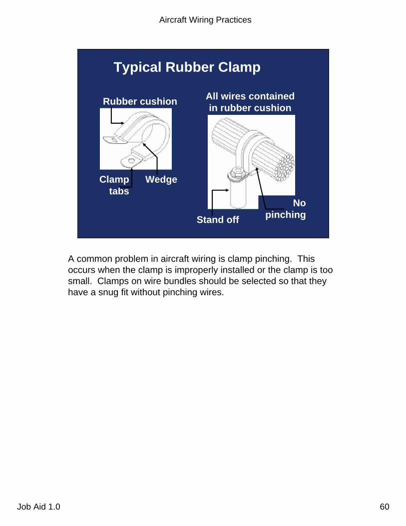
Stand offNo
pinching
Clamp tabs
Rubber cushion
Wedge
Typical Rubber Clamp
All wires contained in rubber cushion
A common problem in aircraft wiring is clamp pinching. This occurs when the clamp is improperly installed or the clamp is too small. Clamps on wire bundles should be selected so that they have a snug fit without pinching wires.

Aircraft Wiring Practices
Job Aid 1.0 61
Typical Nylon Closed-Face Clamp Installation
Do not pinch wire here
It is important when adding wiring to an existing wire bundle toevaluate the existing clamp sizing in order to avoid possible clamp pinching. In some cases it may be necessary to increase the size of the clamps to accommodate the new wiring.

Aircraft Wiring Practices
Job Aid 1.0 62
Engage Clamp Tab in Slot
Incorrect
Clamp slot
Clamp tab
Correct
When using clamp tabs, make sure that the tabs are properly engaged. Otherwise, the tab could become loose and cause subsequent wire damage.
• During wiring installation inspections, ensure that the clamp is snapped before installing and tightening the bolt.
Aircraft Wiring Practices
Job Aid 1.0 63
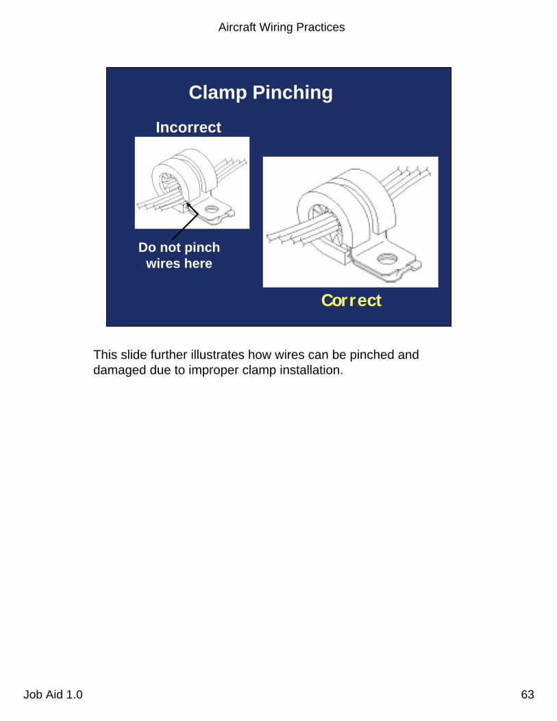
Do not pinch wires here
Correct
Incorrect
Clamp Pinching
This slide further illustrates how wires can be pinched and damaged due to improper clamp installation.
Aircraft Wiring Practices
Job Aid 1.0 64
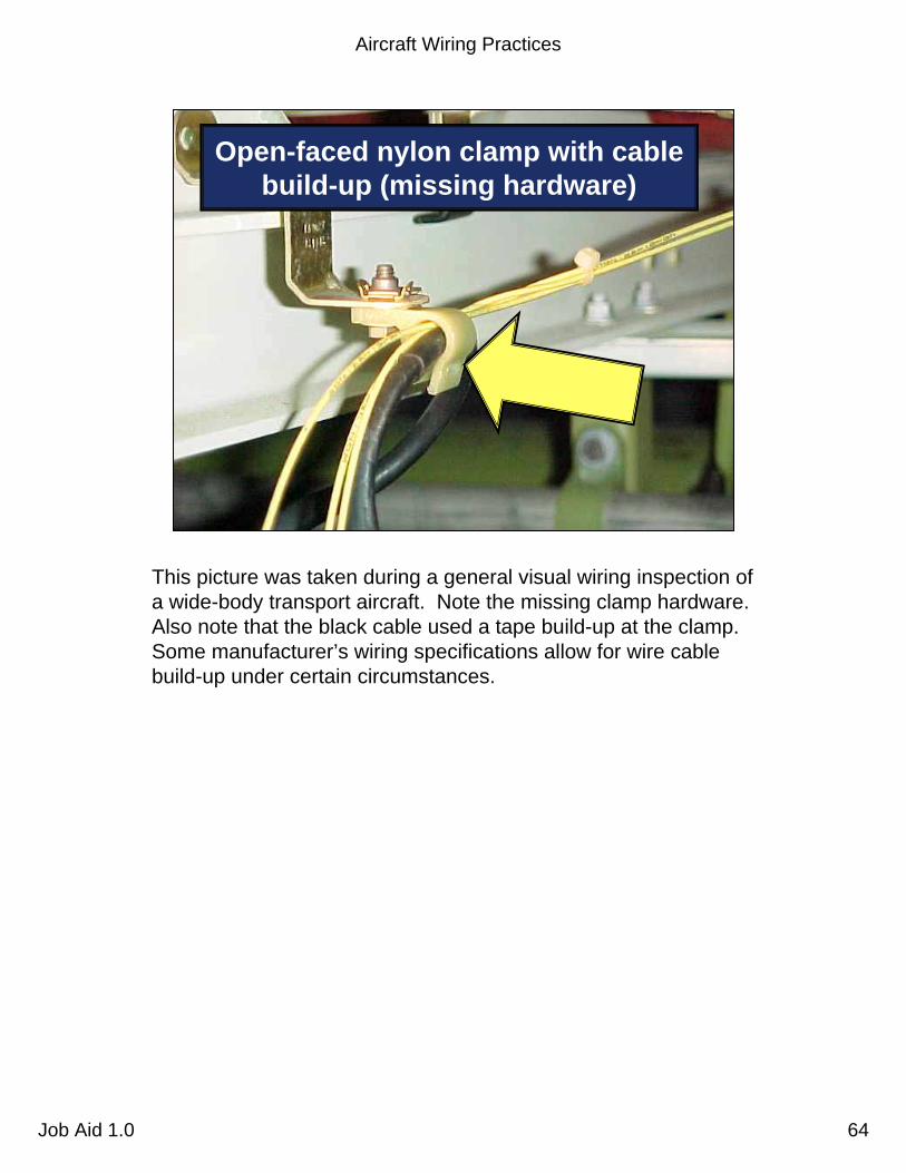
Open-faced nylon clamp with cable build-up (missing hardware)
This picture was taken during a general visual wiring inspection of a wide-body transport aircraft. Note the missing clamp hardware. Also note that the black cable used a tape build-up at the clamp. Some manufacturer’s wiring specifications allow for wire cable build-up under certain circumstances.

Aircraft Wiring Practices
Job Aid 1.0 65
Clamping
Improper
Proper
Too much wiring in a clamp or improperly installed clamps can lead to pinching of the wires.
Aircraft Wiring Practices
Job Aid 1.0 66
Federal AviationAdministration 66Aircraft Wiring Practices Job Aid 1.0
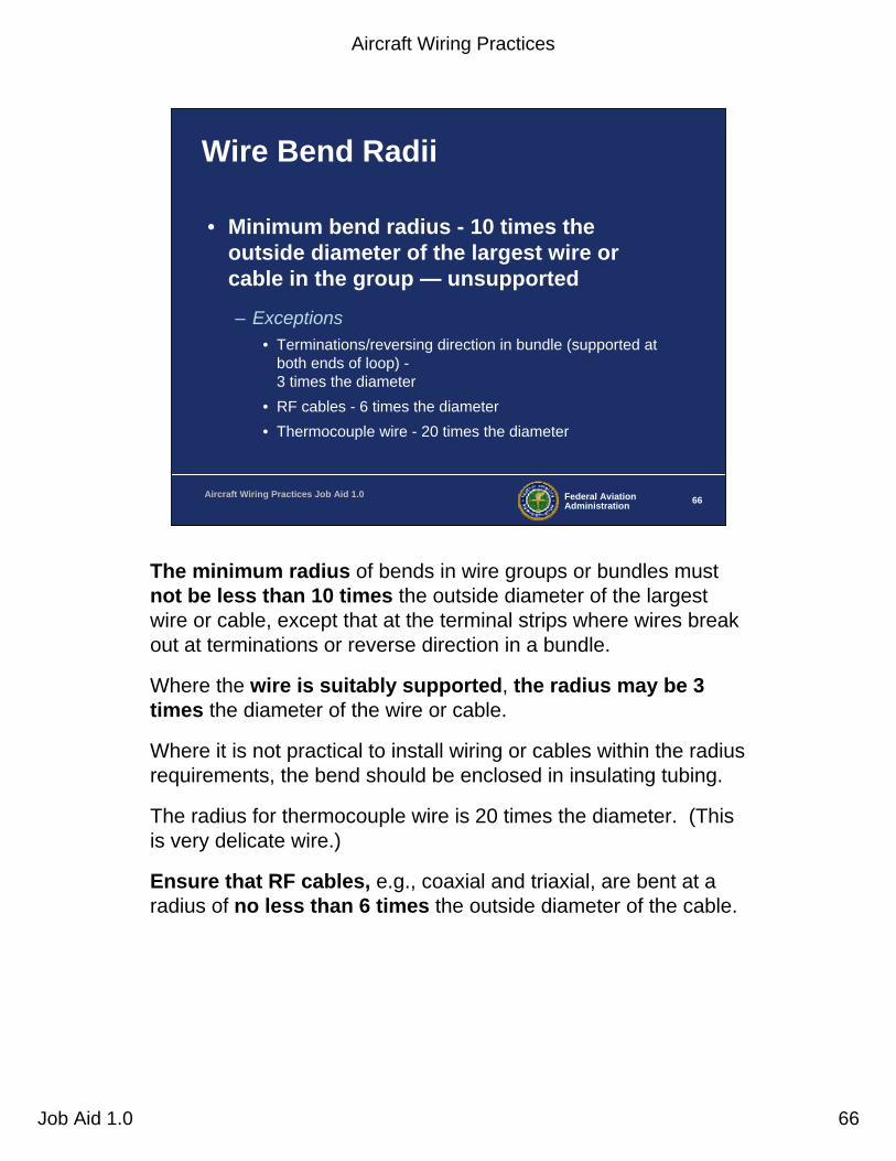
Wire Bend Radii
• Minimum bend radius - 10 times the outside diameter of the largest wire or cable in the group — unsupported
– Exceptions• Terminations/reversing direction in bundle (supported at
both ends of loop) -3 times the diameter
• RF cables - 6 times the diameter• Thermocouple wire - 20 times the diameter
The minimum radius of bends in wire groups or bundles must not be less than 10 times the outside diameter of the largest wire or cable, except that at the terminal strips where wires break out at terminations or reverse direction in a bundle.
Where the wire is suitably supported, the radius may be 3 times the diameter of the wire or cable.
Where it is not practical to install wiring or cables within the radius requirements, the bend should be enclosed in insulating tubing.
The radius for thermocouple wire is 20 times the diameter. (This is very delicate wire.)
Ensure that RF cables, e.g., coaxial and triaxial, are bent at a radius of no less than 6 times the outside diameter of the cable.
Aircraft Wiring Practices
Job Aid 1.0 67
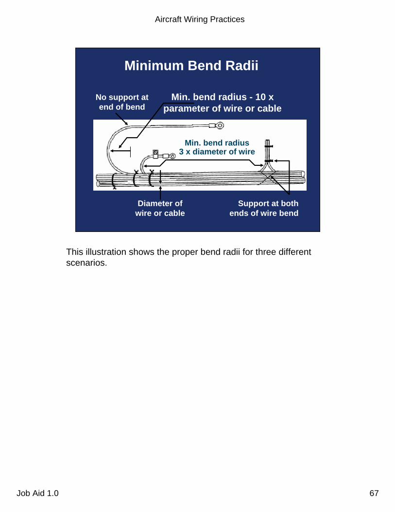
No support at end of bend
Min. bend radius - 10 x parameter of wire or cable
Support at both ends of wire bend
Diameter of wire or cable
Min. bend radius 3 x diameter of wire
Minimum Bend Radii
This illustration shows the proper bend radii for three different scenarios.
Aircraft Wiring Practices
Job Aid 1.0 68
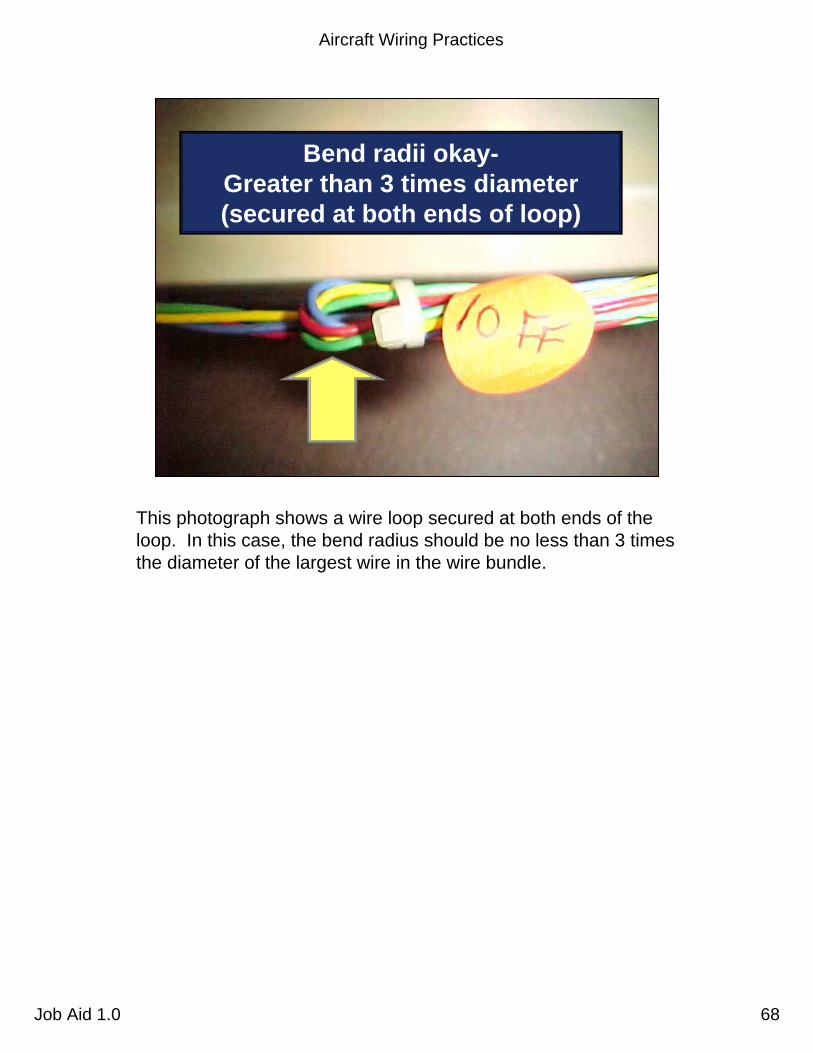
Bend radii okay-Greater than 3 times diameter (secured at both ends of loop)
This photograph shows a wire loop secured at both ends of the loop. In this case, the bend radius should be no less than 3 times the diameter of the largest wire in the wire bundle.

Aircraft Wiring Practices
Job Aid 1.0 69
Bend radii problem-Less than 3 times the diameter
Also supported at each end of the loop, this wire bundle does not meet bend radius standards due to the large wires in the bundle.

Aircraft Wiring Practices
Job Aid 1.0 70
Federal AviationAdministration 70Aircraft Wiring Practices Job Aid 1.0
Unused Wires
• Secured– Tied into a bundle or secured to a permanent
structure
• Individually cut with strands even with insulation
• Pre-insulated, closed-end connector or 1-inch piece of insulating tubing folded and tied back
Ensure that unused wires are individually dead-ended, tied into a bundle, and secured to a permanent structure.
• Each wire should have strands cut even with the insulation and a pre-insulated closed end connector or a 1-inch piece of insulating tubing placed over the wire with its end folded back and tied.
Aircraft Wiring Practices
Job Aid 1.0 71
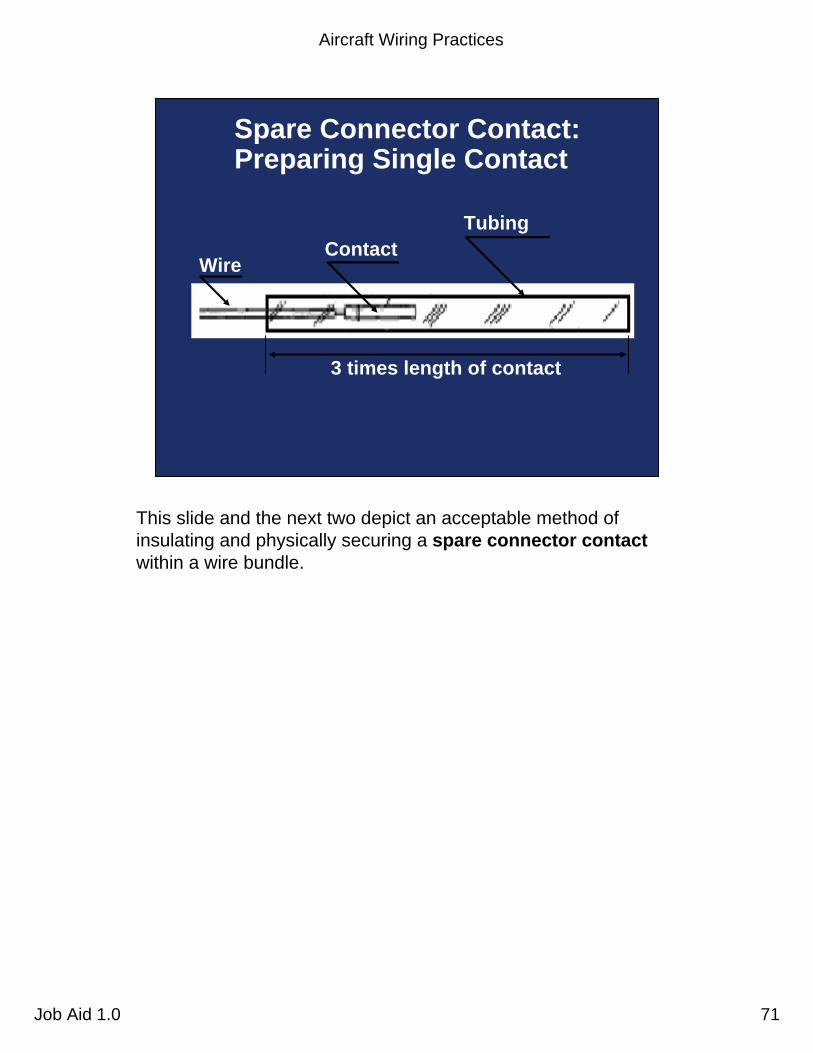
3 times length of contact
WireContact
Tubing
Spare Connector Contact: Preparing Single Contact
This slide and the next two depict an acceptable method of insulating and physically securing a spare connector contactwithin a wire bundle.
Aircraft Wiring Practices
Job Aid 1.0 72
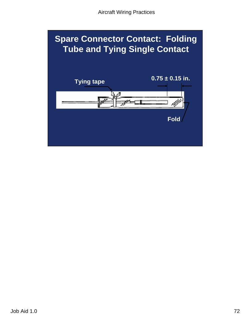
Tying tape 0.75 ± 0.15 in.
Fold
Spare Connector Contact: Folding Tube and Tying Single Contact

Aircraft Wiring Practices
Job Aid 1.0 73
Tying tapeWire bundle
Spare Connector Contact: Single Contact Attachment to Wire Bundle
Aircraft Wiring Practices
Job Aid 1.0 74
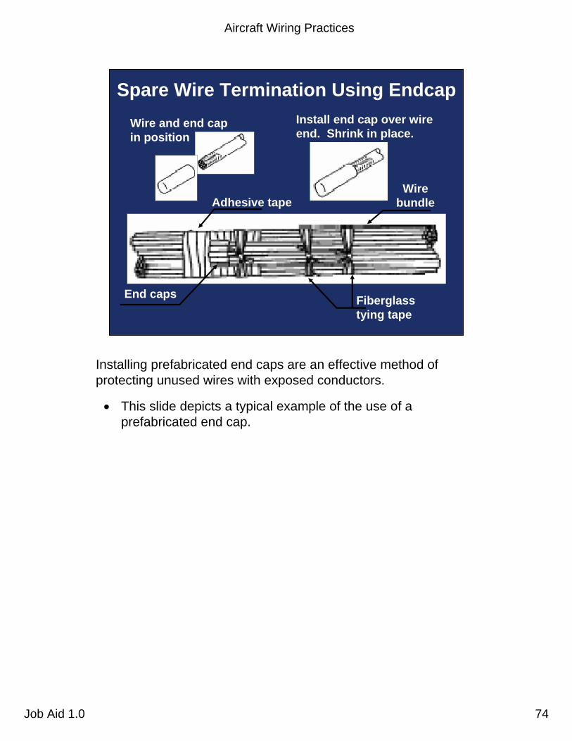
Wire and end cap in position
Install end cap over wire end. Shrink in place.
Fiberglass tying tape
Wire bundle
End caps
Adhesive tape
Spare Wire Termination Using Endcap
Installing prefabricated end caps are an effective method of protecting unused wires with exposed conductors.
• This slide depicts a typical example of the use of a prefabricated end cap.
Aircraft Wiring Practices
Job Aid 1.0 75
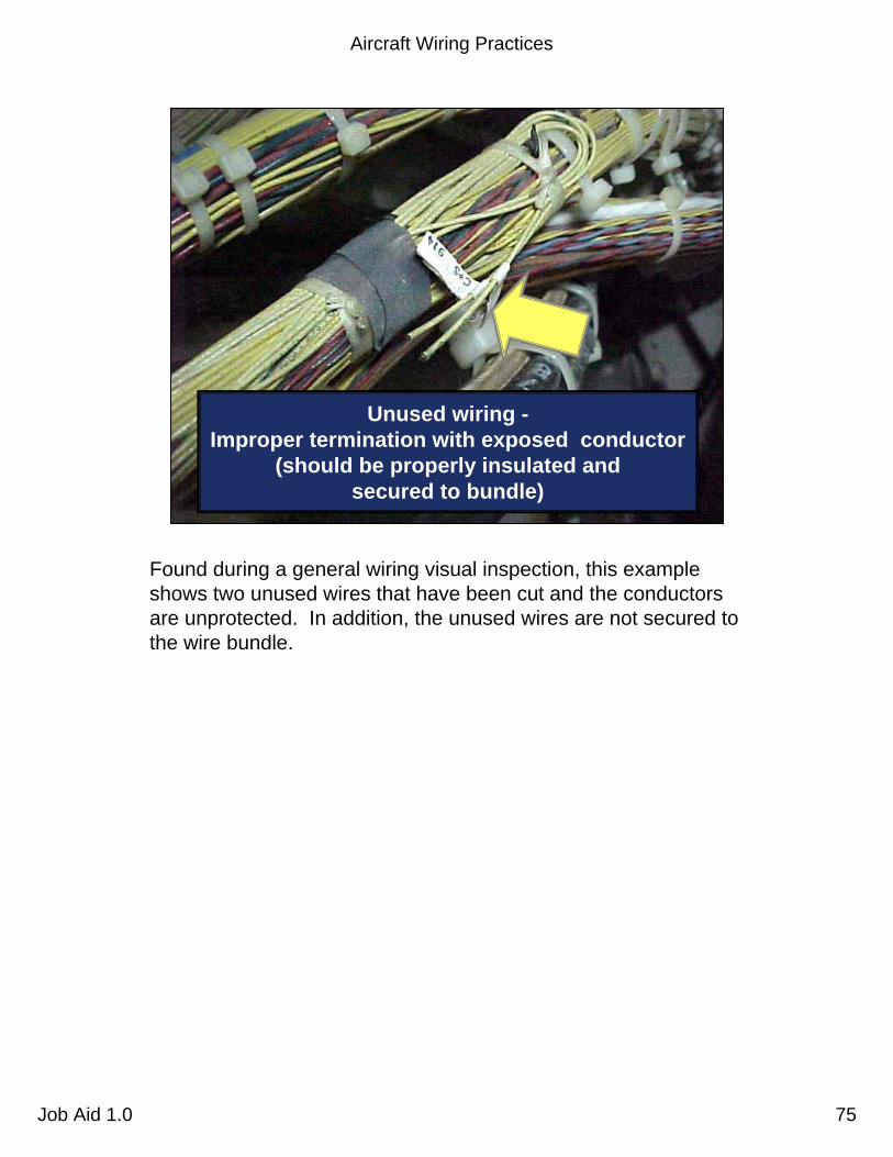
Unused wiring -Improper termination with exposed conductor
(should be properly insulated and secured to bundle)
Found during a general wiring visual inspection, this example shows two unused wires that have been cut and the conductors are unprotected. In addition, the unused wires are not secured to the wire bundle.

Aircraft Wiring Practices
Job Aid 1.0 76
Wire bundle
ties
Coil and stow short wire bundles in low vibration areas
Clamp
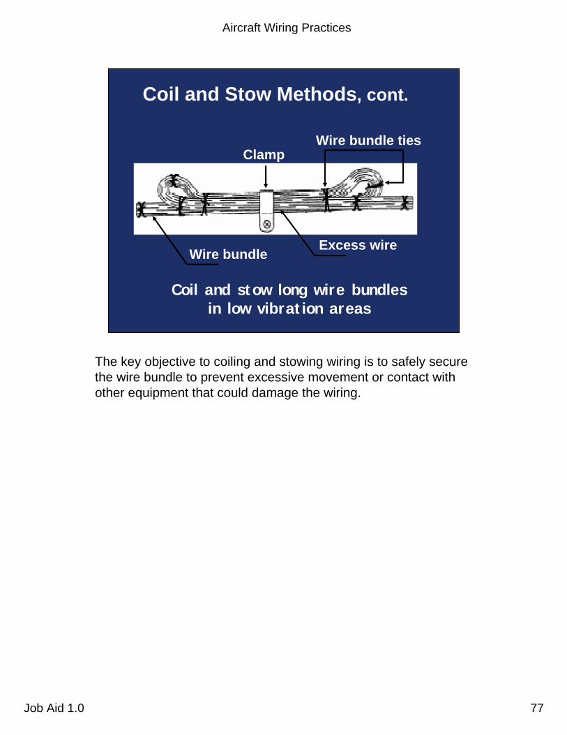
Coil and Stow Methods
Wire bundle
Coil and stow methods are often used to secure excess length of a wire bundle or to secure wire bundles that are not connected to any equipment, such as wiring provisioning for a future installation.
Aircraft Wiring Practices
Job Aid 1.0 77
Coil and Stow Methods, cont.
Wire bundle
Wire bundle ties
Coil and stow long wire bundles in low vibration areas
Clamp
Excess wire
The key objective to coiling and stowing wiring is to safely secure the wire bundle to prevent excessive movement or contact with other equipment that could damage the wiring.
Aircraft Wiring Practices
Job Aid 1.0 78
Coil and stow in medium and high vibration areas
Adjacent wire bundle
Wire bundle Wire
bundle ties
Teflon tape
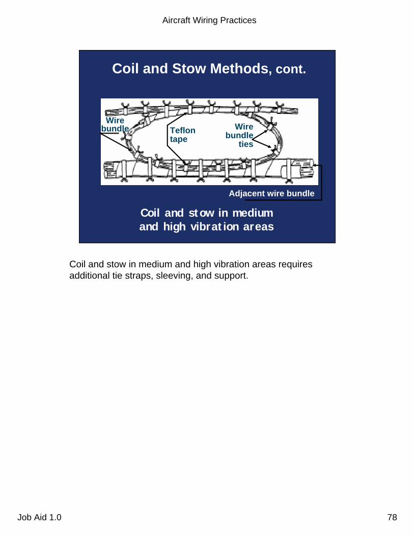
Coil and Stow Methods, cont.
Coil and stow in medium and high vibration areas requires additional tie straps, sleeving, and support.

Aircraft Wiring Practices
Job Aid 1.0 79
Stowing Unused Wires
Improper
Proper

Aircraft Wiring Practices
Job Aid 1.0 80
Federal AviationAdministration 80Aircraft Wiring Practices Job Aid 1.0
Wire Replacement
• Wires should be replaced when:– Chafed or frayed– Insulation suspected of being penetrated– Outer insulation is cracking– Damaged by or known to have been exposed to
electrolyte, oil, hydraulic fluid, etc.
– Evidence of overheating can be seen
Wiring needs to be replaced under a number of circumstances:
• Wiring that has been subjected to chafing or fraying, that has been damaged, or that primary insulation is suspected of being penetrated.
• Wiring on which the outer insulation is brittle when slight flexing causes it to crack.
• Wiring that has weather-cracked outer insulation. NOTE: some wire insulation types appears to be wrinkled when the wire is bent and may not be damaged.
• Wiring that is known to have been exposed to electrolyte or on which the insulation appears to be, or is suspected of being, in an initial stage of deterioration due to the effects of electrolyte.
• There is visible evidence of insulation damage due to overheating.
Aircraft Wiring Practices
Job Aid 1.0 81
Heat Discoloration
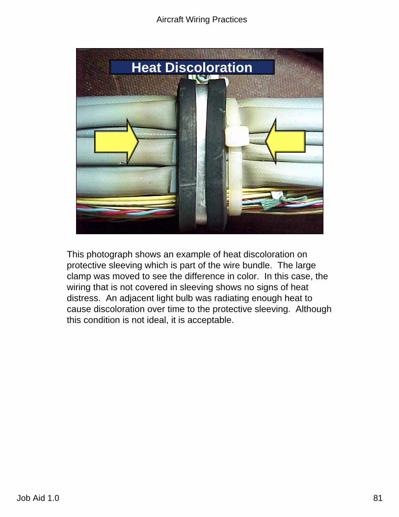
This photograph shows an example of heat discoloration on protective sleeving which is part of the wire bundle. The largeclamp was moved to see the difference in color. In this case, the wiring that is not covered in sleeving shows no signs of heat distress. An adjacent light bulb was radiating enough heat to cause discoloration over time to the protective sleeving. Although this condition is not ideal, it is acceptable.

Aircraft Wiring Practices
Job Aid 1.0 82
Federal AviationAdministration 82Aircraft Wiring Practices Job Aid 1.0
Wire Replacement, cont.
• Wire should be replaced when:– Wire bears evidence of being crushed
or kinked
– Shield on shielded wire if frayed and/or corroded
– Wire shows evidence of breaks, cracks, dirt, or moisture in plastic sleeving
– Sections of wire have splices occurring at less than 10-ft intervals
Continuing, these are additional circumstances that warrant replacing wiring:
• Wiring that bears evidence of having been crushed or severely kinked.
• Shielded wiring on which the metallic shield is frayed and/or corroded. Cleaning agents (which can cause wire damage) or preservatives should not be used to minimize the effects of corrosion or deterioration of wire shields.
• Wiring showing evidence of breaks, cracks, dirt, or moisture in the plastic sleeves placed over wire splices or terminal lugs.
• Sections of wire in which splices occur at less than 10-foot intervals, unless specifically authorized, due to parallel connections, locations, or inaccessibility.

Aircraft Wiring Practices
Job Aid 1.0 83
Federal AviationAdministration 83Aircraft Wiring Practices Job Aid 1.0
Wire Replacement, cont.
• Shielding requirements– Replacement wires must have the same
shielding characteristics as the original wire, such as shield optical coverage and resistance per unit length
– Replacement wires should not be installed outside the bundle shield
Replacement wires should have the same shielding characteristics as the original wires, such as shield optical coverage and resistance per unit length.
If any wires are going to be replaced inside a shielded wire bundle, the replacement wires should not be installed outside the bundle shield.
For more information on shielding, the Lightning/HIRF Video and Self-study Guide is available. (To obtain, see your Directorate training manager.)
Aircraft Wiring Practices
Job Aid 1.0 84
Correct procedure
Incorrect procedure
Chafing
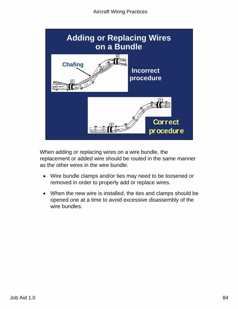
Adding or Replacing Wires on a Bundle
When adding or replacing wires on a wire bundle, the replacement or added wire should be routed in the same manner as the other wires in the wire bundle.
• Wire bundle clamps and/or ties may need to be loosened or removed in order to properly add or replace wires.
• When the new wire is installed, the ties and clamps should be opened one at a time to avoid excessive disassembly of the wire bundles.

Aircraft Wiring Practices
Job Aid 1.0 85
Adding Wires on a BundleImproperly routed outside of the tie wrap that secures the clamp
Properly routed

Aircraft Wiring Practices
Job Aid 1.0 86
Federal AviationAdministration 86Aircraft Wiring Practices Job Aid 1.0
Wire Splicing
• Keep to a minimum
• Avoid in high vibration areas
• Locate to permit inspection
• Stagger in bundles to minimize increase in bundle size
• Use self-insulated splice connector, if possible
Splicing is permitted on wiring as long as it does not affect the reliability and the electro-mechanical characteristics of the wiring. Splicing of power wires, co-axial cables, multiplex bus, and large gauge wire should be avoided. If it can’t be avoided, then the power wire splicing must have approved data.
• Splicing of electrical wire should be kept to a minimum and avoided entirely in locations subject to extreme vibrations. Splicing of individual wires in a group or bundle should have engineering approval and the splice(s) should be located to allow periodic inspection.
Many types of aircraft splice connectors are available for use when splicing individual wires.
• Use of a self-insulated splice connector is preferred; however, a non-insulated splice connector may be used provided the splice is covered with plastic sleeving that is secured at both ends.
• Environmentally-sealed splices that conform to MIL-T-7928 provide a reliable means of splicing in SWAMP areas. However, a non-insulated splice connector may be used, provided the splice is covered with dual wall shrink sleeving of a suitable material.

Aircraft Wiring Practices
Job Aid 1.0 87
Staggered Splices
Splices in bundles should be staggered so as to minimize any increase in the size of the bundle that would:
• Prevent bundle from fitting into designated space.
• Cause congestion adversely affecting maintenance.
• Cause stress on the wires.

Aircraft Wiring Practices
Job Aid 1.0 88
Overheated wire at the splice
Splices that are not crimped properly (under or over) can cause increased resistance leading to overheat conditions.
Aircraft Wiring Practices
Job Aid 1.0 89
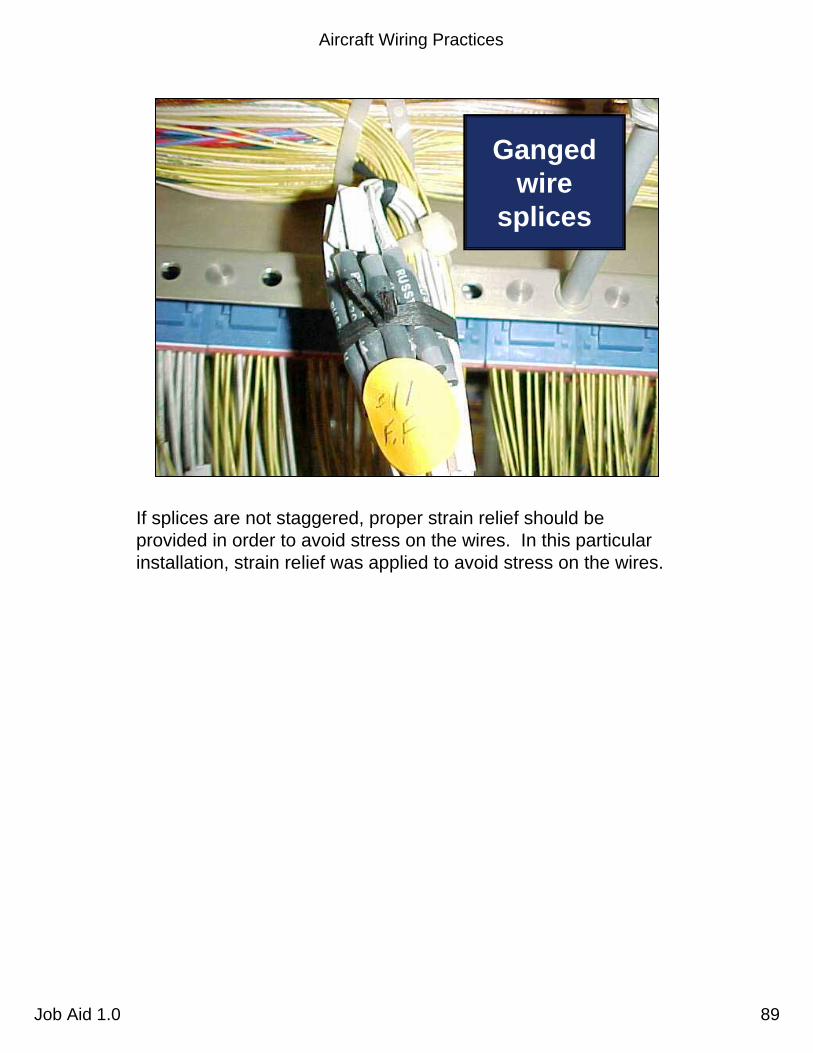
Ganged wire
splices
If splices are not staggered, proper strain relief should be provided in order to avoid stress on the wires. In this particular installation, strain relief was applied to avoid stress on the wires.

Aircraft Wiring Practices
Job Aid 1.0 90
Ganged wire splices
The top two wires in this photo are experiencing stress due to apreload condition. Also note that the wire bundle is not properly clamped.

Aircraft Wiring Practices
Job Aid 1.0 91
Federal AviationAdministration 91Aircraft Wiring Practices Job Aid 1.0
Terminals
• Tensile strength of the wire-to-terminal joint should be at least the equivalent tensile strength of the wire
• Resistance of the wire-to-terminal joint should be negligible relative to the normal resistance of the wire
Tensile strength terminals are attached to the ends of electrical wires to facilitate connection of the wires to terminal strips or items of equipment. The tensile strength of the wire-to-terminal joint should be at least equivalent to the tensile strength of the wire itself.
Resistance of wire-to-terminal joint should be negligible, relative to the normal resistance of the wire.
• Selection of wire terminals. The following should be considered in the selection of wire terminals.
- Current rating.- Wire size (gauge) and insulation diameter.- Conductor material compatibility.- Stud size.- Insulation material compatibility.- Application environment.- Solder/solderless.
Aircraft Wiring Practices
Job Aid 1.0 92
Brazedjoint
Position of tongue before
bending
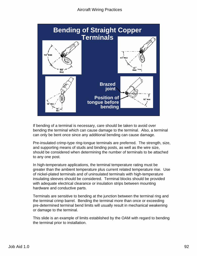
Bending of Straight Copper Terminals
If bending of a terminal is necessary, care should be taken to avoid over bending the terminal which can cause damage to the terminal. Also, a terminal can only be bent once since any additional bending can cause damage.
Pre-insulated crimp-type ring-tongue terminals are preferred. The strength, size, and supporting means of studs and binding posts, as well as the wire size, should be considered when determining the number of terminals to be attached to any one post.
In high-temperature applications, the terminal temperature rating must be greater than the ambient temperature plus current related temperature rise. Use of nickel-plated terminals and of uninsulated terminals with high-temperature insulating sleeves should be considered. Terminal blocks should be provided with adequate electrical clearance or insulation strips between mounting hardware and conductive parts.
Terminals are sensitive to bending at the junction between the terminal ring and the terminal crimp barrel. Bending the terminal more than once or exceeding pre-determined terminal bend limits will usually result in mechanical weakening or damage to the terminal.
This slide is an example of limits established by the OAM with regard to bending the terminal prior to installation.
Aircraft Wiring Practices
Job Aid 1.0 93
Federal AviationAdministration 93Aircraft Wiring Practices Job Aid 1.0
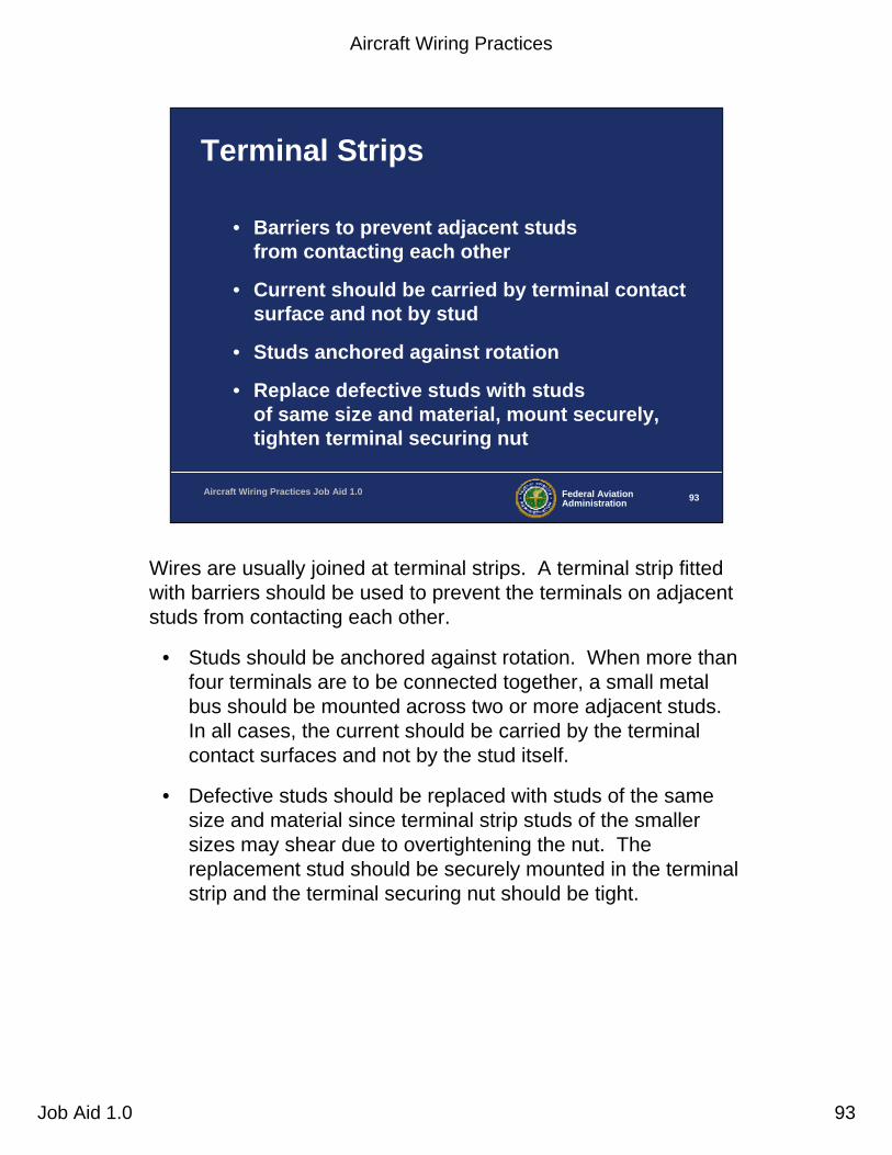
Terminal Strips
• Barriers to prevent adjacent studs from contacting each other
• Current should be carried by terminal contact surface and not by stud
• Studs anchored against rotation
• Replace defective studs with studs of same size and material, mount securely, tighten terminal securing nut
Wires are usually joined at terminal strips. A terminal strip fitted with barriers should be used to prevent the terminals on adjacent studs from contacting each other.
• Studs should be anchored against rotation. When more than four terminals are to be connected together, a small metal bus should be mounted across two or more adjacent studs. In all cases, the current should be carried by the terminal contact surfaces and not by the stud itself.
• Defective studs should be replaced with studs of the same size and material since terminal strip studs of the smaller sizes may shear due to overtightening the nut. The replacement stud should be securely mounted in the terminal strip and the terminal securing nut should be tight.

Aircraft Wiring Practices
Job Aid 1.0 94
Federal AviationAdministration 94Aircraft Wiring Practices Job Aid 1.0
Terminal Strips, cont.
• Mount strips so loose metallic objects cannot fall across terminal
– Provide spare stud for breaks and future expansion
– Inspect terminal periodically for loose connections, metallic objects, dirt, and grease accumulation
• Can cause arcing, resulting in fire or systems failure
Terminal strips should be mounted in such a manner that loose metallic objects cannot fall across the terminals or studs. It is good practice to provide at least one spare stud for future circuit expansion or in case a stud is broken.
• Terminal strips should be inspected for loose connections, metallic objects that may have fallen across the terminal strip,dirt and grease accumulation, etc. These conditions can cause arcing which may result in a fire, or system failures.

Aircraft Wiring Practices
Job Aid 1.0 95
Terminals on circuit breakers
Connectors and terminals in aircraft require special attention to ensure a safe and satisfactory installation. Every possibility of terminals not being torqued properly, due to misinstallation, poor maintenance, and service life, should be addressed in the design.
• Electrical equipment malfunction has frequently been traced to poor terminal connections at terminal boards.
• Loose contact surfaces can produce localized heating that may ignite nearby combustible materials or overheat adjacent wire insulation.
Note the green torque stripes painted on the terminal fasteners in this picture. This is an excellent method to quickly determine if a terminal fastener is still torqued to its original value.

Aircraft Wiring Practices
Job Aid 1.0 96
Power feeder terminals
Again, you can see the red colored torque stripes applied to these high current power feeder terminations. High current terminals are more sensitive to increased resistance due to a improperly torqued terminal.
• As a side note, the power feeder cables should not be touching each other without being suitably tied with spacers or other securing device.
Aircraft Wiring Practices
Job Aid 1.0 97
Federal AviationAdministration 97Aircraft Wiring Practices Job Aid 1.0
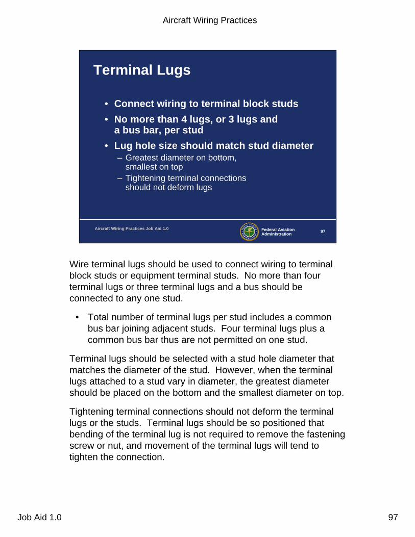
Terminal Lugs
• Connect wiring to terminal block studs• No more than 4 lugs, or 3 lugs and
a bus bar, per stud• Lug hole size should match stud diameter
– Greatest diameter on bottom, smallest on top
– Tightening terminal connections should not deform lugs
Wire terminal lugs should be used to connect wiring to terminal block studs or equipment terminal studs. No more than four terminal lugs or three terminal lugs and a bus should be connected to any one stud.
• Total number of terminal lugs per stud includes a common bus bar joining adjacent studs. Four terminal lugs plus a common bus bar thus are not permitted on one stud.
Terminal lugs should be selected with a stud hole diameter that matches the diameter of the stud. However, when the terminal lugs attached to a stud vary in diameter, the greatest diameter should be placed on the bottom and the smallest diameter on top.
Tightening terminal connections should not deform the terminal lugs or the studs. Terminal lugs should be so positioned that bending of the terminal lug is not required to remove the fastening screw or nut, and movement of the terminal lugs will tend to tighten the connection.

Aircraft Wiring Practices
Job Aid 1.0 98
Federal AviationAdministration 98Aircraft Wiring Practices Job Aid 1.0
Terminal Lugs, cont.
• Aluminum lugs– Crimped to aluminum wire only
• Special attention needed to guard against excessive voltage drop at terminal junction
– Inadequate terminal contact area– Stacking errors– Improper torquing
– Use calibrated crimp tools
Aluminum terminal lugs should be crimped to aluminum wire only. The tongue of the aluminum terminal lugs or the total number of tongues of aluminum terminal lugs when stacked, should be sandwiched between two flat washers (cadmium plated) when terminated on terminal studs. Spacers or washers should not be used between the tongues of like material terminal lugs. Special attention should be given to aluminum wire and cable installations to guard against conditions that would result in excessive voltage drop and high resistance at junctions that may ultimately lead to failure of the junction. • Examples of such conditions are improper installation of terminals and
washers, improper torsion (“torquing” of nuts), and inadequate terminal contact areas.
Note that aluminum wire is normally used in sizes of 10 gauge and larger to carry electrical power in large transport category aircraft in order to save weight. Although not as good a conductor as copper, aluminum is lighter when compared to copper and the weight savings can be significant for a large aircraft that may have several hundred feet of power feeder cable.Because aluminum is used primarily for high current power applications, the terminal junctions are more sensitive to conditions leading to increased junction resistance which can cause arcing and localized heat distress.

Aircraft Wiring Practices
Job Aid 1.0 99
Flat washer
Lock washer
NutTerminal Stacking
(like materials)
Terminal stud
Copper terminal
lugs
Terminal stacking materials and methods
• Multiple wires often terminate onto a single terminal stud. Care should be taken to install the terminal properly. The materials that the terminals are constructed of will impact the type of stacking methods used. Dissimilar metals, when in contact, can produce electrolysis that can cause corrosion, thus degrading the terminal junction resistance and causing arcing or hot spots.
• For stacking terminals that are made of like materials, the terminals can be stacked directly on top of each other.

Aircraft Wiring Practices
Job Aid 1.0 100
Terminal Stacking(unlike materials)
Copper terminal
Flat washer
Lock washer
Terminal stud
Nut
Aluminum terminalsFlat
washers
When stacking unlike materials together, e.g., aluminum and copper, a cadmium-plated flat washer is usually needed to isolate the dissimilar metals.

Aircraft Wiring Practices
Job Aid 1.0 101
Terminal Stacking Methods
One-Sided Entry With Two Terminals
Flat washer
Lock washer
Nut
Crimp barrel (belly up) Crimp barrel
(belly down)
When two terminals are installed on one side of the terminal strip, care should be taken to ensure that the terminal crimp barrels do not interfere with one another. One method to avoid this problem is to install the terminals with the barrels “back to back.”
Aircraft Wiring Practices
Job Aid 1.0 102
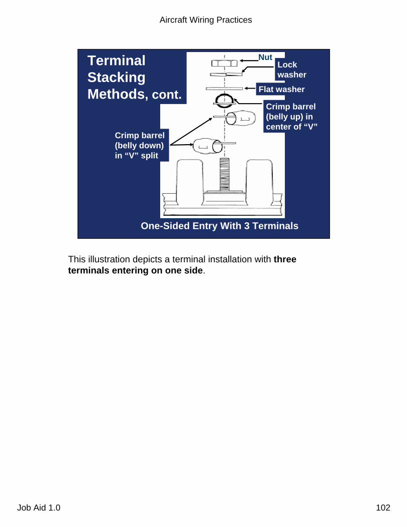
One-Sided Entry With 3 Terminals
Flat washer
Lock washer
Crimp barrel (belly down) in “V” split
Crimp barrel (belly up) in center of “V”
Terminal Stacking Methods, cont.
Nut
This illustration depicts a terminal installation with three terminals entering on one side.
Aircraft Wiring Practices
Job Aid 1.0 103
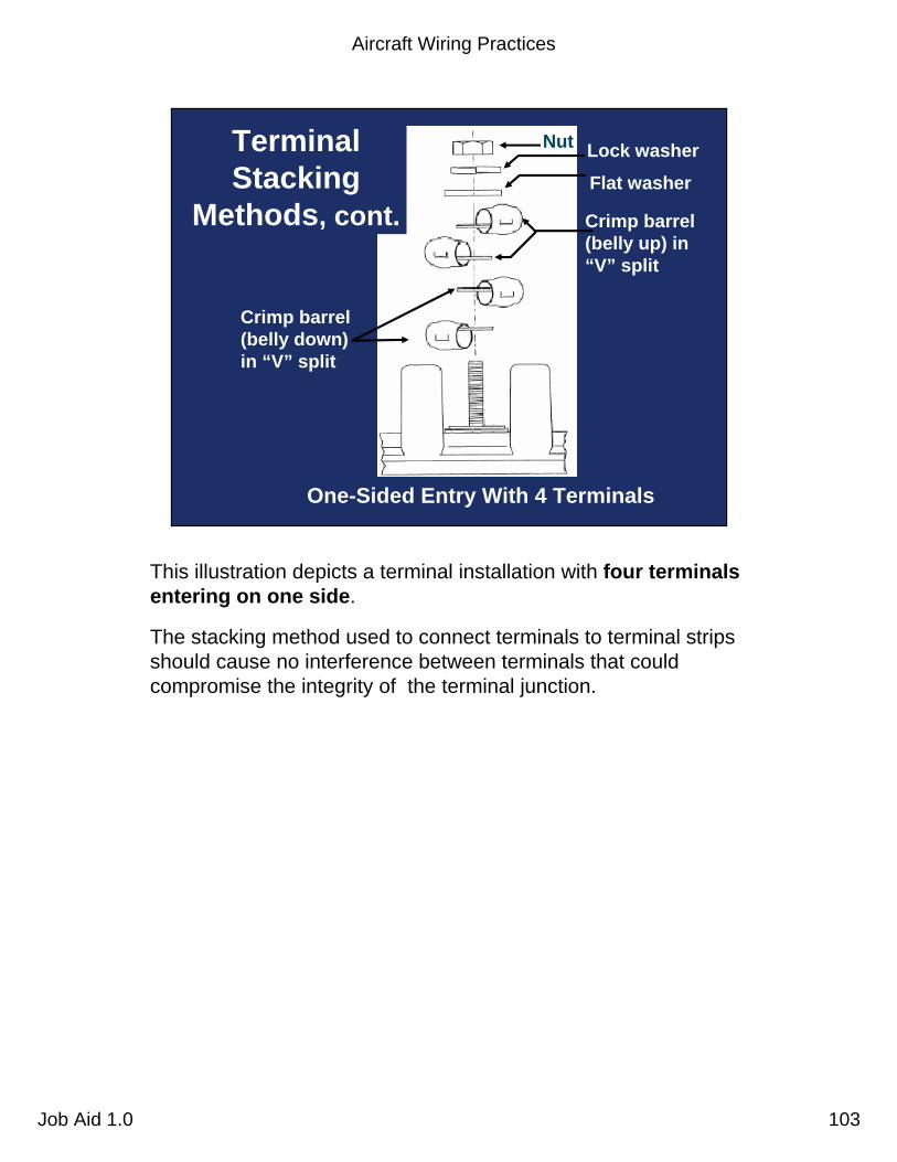
One-Sided Entry With 4 Terminals
Terminal Stacking
Methods, cont.
Nut
Flat washer
Lock washer
Crimp barrel (belly up) in “V” split
Crimp barrel (belly down) in “V” split
This illustration depicts a terminal installation with four terminals entering on one side.
The stacking method used to connect terminals to terminal stripsshould cause no interference between terminals that could compromise the integrity of the terminal junction.
Aircraft Wiring Practices
Job Aid 1.0 104
Nut
Flat washer
Lock washer
Incorrect Correct
Lock washer not compressed
Lock washer compressed
Space
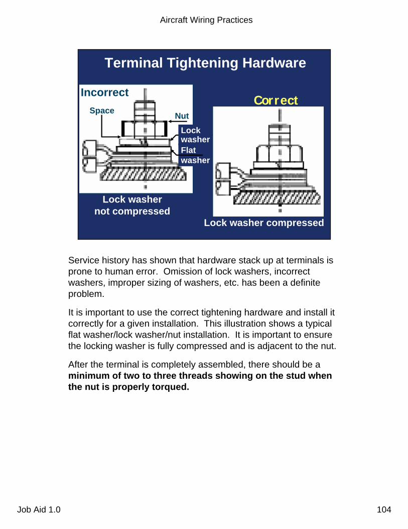
Terminal Tightening Hardware
Service history has shown that hardware stack up at terminals isprone to human error. Omission of lock washers, incorrect washers, improper sizing of washers, etc. has been a definite problem.
It is important to use the correct tightening hardware and install it correctly for a given installation. This illustration shows a typical flat washer/lock washer/nut installation. It is important to ensure the locking washer is fully compressed and is adjacent to the nut.
After the terminal is completely assembled, there should be a minimum of two to three threads showing on the stud when the nut is properly torqued.

Aircraft Wiring Practices
Job Aid 1.0 105
Steel washers
Non-self locking nut
Split lock washer
Aluminum terminal
Improperly-sized washer
Raised portion of terminal
Correct
Washer Size Selection
It is important to select and use the correct size washers in any termination. Undersized or oversized washers can lead to increased junction resistance and localized heat or arcing.
This illustration shows how an improperly sized washer can lead to insufficient contact between the terminal and terminal lug.
Aircraft Wiring Practices
Job Aid 1.0 106
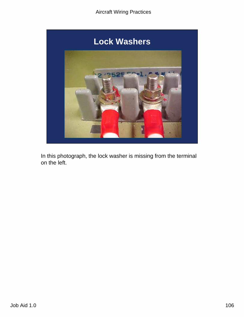
Lock Washers
In this photograph, the lock washer is missing from the terminalon the left.

Aircraft Wiring Practices
Job Aid 1.0 107
Federal AviationAdministration 107Aircraft Wiring Practices Job Aid 1.0
Grounding Definition
• Grounding is the process of electrically connecting conductive objects to either a conductive structure or some other conductive return path for the purpose of safely completing either a normal or fault circuit.
Grounding. One of the more important factors in the design and maintenance of aircraft electrical systems is proper bonding andgrounding. Inadequate bonding or grounding can lead to unreliable operation of systems, such as EMI, electrostatic discharge damage to sensitive electronics, personnel shock hazard, or damage from lightning strike.
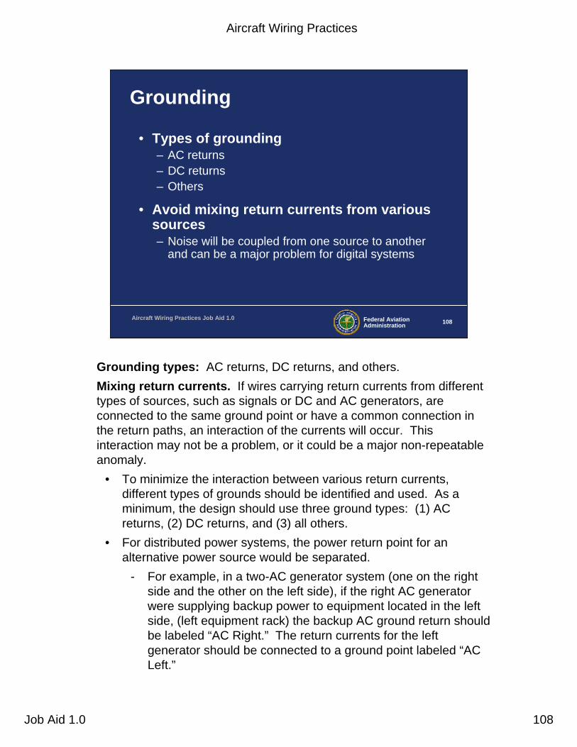
Aircraft Wiring Practices
Job Aid 1.0 108
Federal AviationAdministration 108Aircraft Wiring Practices Job Aid 1.0
Grounding
• Types of grounding– AC returns– DC returns– Others
• Avoid mixing return currents from various sources – Noise will be coupled from one source to another
and can be a major problem for digital systems
Grounding types: AC returns, DC returns, and others.Mixing return currents. If wires carrying return currents from different types of sources, such as signals or DC and AC generators, are connected to the same ground point or have a common connection in the return paths, an interaction of the currents will occur. This interaction may not be a problem, or it could be a major non-repeatable anomaly.
• To minimize the interaction between various return currents, different types of grounds should be identified and used. As a minimum, the design should use three ground types: (1) AC returns, (2) DC returns, and (3) all others.
• For distributed power systems, the power return point for an alternative power source would be separated.
- For example, in a two-AC generator system (one on the right side and the other on the left side), if the right AC generator were supplying backup power to equipment located in the left side, (left equipment rack) the backup AC ground return should be labeled “AC Right.” The return currents for the left generator should be connected to a ground point labeled “AC Left.”
Aircraft Wiring Practices
Job Aid 1.0 109
Federal AviationAdministration 109Aircraft Wiring Practices Job Aid 1.0
Grounding, cont.
• Design of ground path should be given as much attention as other leads in the system
• Grounding should provide a constant impedance
• Ground equipment items externally even when internally grounded– Avoid direct connections to magnesium structure for
ground return
Design of ground paths. The design of the ground return circuit should be given as much attention as the other leads of a circuit.
Constant impedance. A requirement for proper ground connections is that they maintain an impedance that is essentially constant.
• Ground return circuits should have a current rating and voltage drop adequate for satisfactory operation of the connected electrical and electronic equipment.
• EMI problems, that can be caused by a system’s power wire, can be reduced substantially by locating the associated ground return near the origin of the power wiring (e.g., circuit breaker panel) and routing the power wire and its ground return in a twisted pair.
• Special care should be exercised to ensure replacement on groundreturn leads. The use of numbered insulated wire leads instead of bare grounding jumpers may aid in this respect.
External grounding of equipment items. In general, equipment items should have an external ground connection, even when internally grounded. Direct connections to a magnesium structure (which may create a fire hazard) must not be used for ground return.

Aircraft Wiring Practices
Job Aid 1.0 110
Federal AviationAdministration 110Aircraft Wiring Practices Job Aid 1.0
Grounding, cont.
• Heavy current grounds– Attach to individual grounding brackets attached to
aircraft structure with a proper metal-to-metal bond
– Accommodate normal and fault currents of system without creating excessive voltage drop or damage to structure
– Give special attention to composite aircraft
Heavy-current grounds. Power ground connections for generators, transformer rectifiers, batteries, external power receptacles, and other heavy-current loads must be attached to individual grounding brackets that are attached to aircraft structure with a proper metal-to-metal bonding attachment.
• This attachment and the surrounding structure must provide adequate conductivity to accommodate normal and fault currents of the system without creating excessive voltage drop or damage to the structure.
• At least three fasteners, located in a triangular or rectangularpattern, must be used to secure such brackets in order to minimize susceptibility to loosening under vibration.
• If the structure is fabricated of a material such as carbon fiber composite (CFC), which has a higher resistivity than aluminum or copper, it will be necessary to provide an alternative ground path(s) for power return current.
Aircraft Wiring Practices
Job Aid 1.0 111
Federal AviationAdministration 111Aircraft Wiring Practices Job Aid 1.0
Bonding
• Equipment bonding– Low impedance paths to aircraft structure
required for electronic equipment to provide radio frequency return circuits
– Facilitates reduction in EMI for most electrical equipment
• Cases of components that produce EMI should be grounded to structure
Equipment bonding. Low-impedance paths to aircraft structure are normally required for electronic equipment to provide radio frequency return circuits and for most electrical equipment to facilitate reduction in EMI. The cases of components that produce electromagnetic energy should be grounded to structure.
• To ensure proper operation of electronic equipment, it is particularly important to conform the system’s installation specification when inter-connections, bonding, and grounding are being accomplished.
Aircraft Wiring Practices
Job Aid 1.0 112
Federal AviationAdministration 112Aircraft Wiring Practices Job Aid 1.0
Bonding, cont.
• Metallic surface bonding– Electrically connecting conductive exterior airframe
components through mechanical joints, conductive hinges, or bond straps
• Protects against static charges and lightning strikes
Metallic surface bonding. All conducting objects on the exterior of the airframe must be electrically connected to the airframe through mechanical joints, conductive hinges, or bond straps capable of conducting static charges and lightning strikes.
• Exceptions may be necessary for some objects such as antenna elements, whose function requires them to be electrically isolated from the airframe. Such items should be provided with an alternative means to conduct static charges and/or lightning currents, as appropriate.

Aircraft Wiring Practices
Job Aid 1.0 113
Federal AviationAdministration 113Aircraft Wiring Practices Job Aid 1.0
Bonding, cont.
• Static bonds– Required for all isolated conducting parts with
area greater than 3 in2 and a linear dimension over 3" subjected to appreciable electrostatic charging due to precipitation, fluid, or air in motion
• Resistance of less than 1 ohm when clean and dry usually ensures static dissipation on larger objects
Static bonds. All isolated conducting parts inside and outside the aircraft, having an area greater than 3 in2 and a linear dimension over 3 inches, that are subjected to appreciable electrostatic charging due to precipitation, fluid, or air in motion, should have a mechanically secure electrical connection to the aircraft structure of sufficient conductivity to dissipate possible static charges.
• A resistance of less than 1 ohm when clean and dry will generally ensure such dissipation on larger objects. Higher resistances are permissible in connecting smaller objects to airframe structure.

Aircraft Wiring Practices
Job Aid 1.0 114
Federal AviationAdministration 114Aircraft Wiring Practices Job Aid 1.0
Wire Marking
• Necessary for:– Safety of operation– Safety to maintenance personnel– Ease of maintenance
• To identify performance capability, use wire material part number and five digit/letter code identifying manufacturer
Purpose. The proper identification of electrical wires and cables with their circuits and voltages is necessary to provide safety of operation, safety to maintenance personnel, and ease of maintenance.
Common manufacturer marking process. Each wire and cable should be marked with a part number. It is common practice for wire manufacturers to follow the wire material part number with the five digit/letter C.A.G.E. code identifying the wire manufacturer. Using this code, existing installed wire that needs replacement can be identified as to its performance capabilities. This helps to prevent the inadvertent use of lower performance and unsuitable replacement wire.
• NOTE: Special care should be taken when hot stamping wire. Service history has shown problems associated with hot stamping due to insulation damage caused during the process.
• The method of identification should not impair the characteristics of the wiring.
• Original wire identification. To facilitate installation and maintenance, retain the original wire-marking identification. The wire identification marks should consist of a combination of letters and numbers that identify the wire, the circuit it belongs to, its gauge size, and any other information to relate the wire to a wiring diagram. All markings should be legible in size, type, and color.
• Identification and information related to the wire and wiring diagrams. The wire identification marking should consist of similar information to relate the wire to a wiring diagram.

Aircraft Wiring Practices
Job Aid 1.0 115
Federal AviationAdministration 115Aircraft Wiring Practices Job Aid 1.0
Wire Marking, cont.
• Wire identification marks identify wire, circuit, and gauge size
• Markings should be legible in size, type, and color at 15-inch maximum intervals along the wire [directly on wire or indirect (sleeve/tag)]
• <3 inches needs no marking– Readable without removing clamps, ties, or
supporting devices
Marking wires in aircraft. Identification markings generally are placed at each end of the wire and at 15-inch maximum intervals along the length of the wire.
• Wires less than 3 inches long need not be identified. • Wires 3 to 7 inches in length should be identified approximately at the center. • Added identification marker sleeves should be located so that ties, clamps, or
supporting devices need not be re-moved in order to read the identification. • The wire identification code must be printed to read horizontally (from left to right) or
vertically (from top to bottom). The two methods of marking wire or cable are as follows:
- (1) Direct marking is accomplished by printing the cable’s outer covering. - (2) Indirect marking is accomplished by printing a heat-shrinkable sleeve and
installing the printed sleeve on the wire or cables outer covering. Indirect-marked wire or cable should be identified with printed sleeves at each end and at intervals not longer than 6 feet. The individual wires inside a cable should be identified within 3 inches of their termination.
• The marking should be permanent such that environmental stresses during operation and maintenance do not adversely affect legibility.
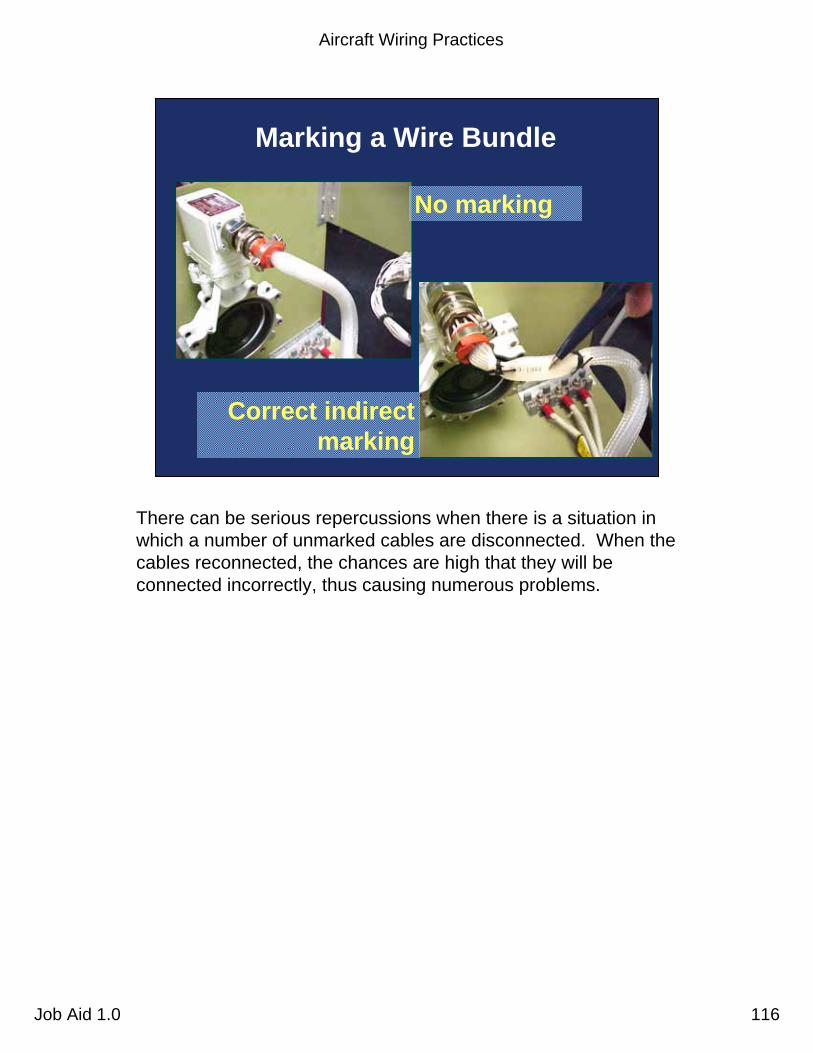
Aircraft Wiring Practices
Job Aid 1.0 116
Marking a Wire Bundle
No marking
Correct indirect marking
There can be serious repercussions when there is a situation in which a number of unmarked cables are disconnected. When the cables reconnected, the chances are high that they will be connected incorrectly, thus causing numerous problems.

Aircraft Wiring Practices
Job Aid 1.0 117
Federal AviationAdministration 117Aircraft Wiring Practices Job Aid 1.0
Connectors
• Many types, however crimped contacts generally used– Circular type– Rectangular– Module blocks
• Selected to provide max. degree of safety and reliability given electrical and environmental requirements– Use environmentally-sealed connectors to prevent moisture
penetration
Connectors. The number and complexity of wiring systems have resulted in an increased use of electrical connectors. The proper choice and application of connectors is a significant part of the aircraft wiring system. Connectors should be kept to a minimum, selected, and installed to provide the maximum degree of safety and reliability to the aircraft. For the installation of any particular connector assembly, the specification of the manufacturer should be followed.Purpose and types. The connector used for each application should be selected only after a careful determination of the electrical and environmental requirements. Consider the size, weight, tooling, logistic, maintenance support, and compatibility with standardization programs.
• For ease of assembly and maintenance, connectors using crimped contacts are generally chosen for all applications except those requiring a hermetic seal.
• A replacement connector of the same basic type and design as the connector it replaces should be used.
• With a crimp type connector for any electrical connection, the proper insertion, or extraction tool should be used to install or remove wires from such a connector. Refer to manufacturer or aircraft instruction manual.
• After the connector is disconnected, inspect it for loose soldered connections to prevent unintentional grounding.
• Connectors that are susceptible to corrosion difficulties may be treated with a chemically inert waterproof jelly or an environmentally-sealed connector may be used.
• NOTE: Although not required by AC 43.13-1b, moisture-proof connectors should be used in all areas of the aircraft, including the cabin. Service history indicates that most connector failures occur due to some form of moisture penetration. Even in the pressurized, environmentally-controlled areas of the cockpit and cabin, moisture can occur due to “rain in the plane” type of condensation that generally is a problem in all modern transport category aircraft.
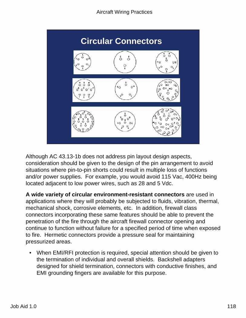
Aircraft Wiring Practices
Job Aid 1.0 118
Circular Connectors
Although AC 43.13-1b does not address pin layout design aspects, consideration should be given to the design of the pin arrangement to avoid situations where pin-to-pin shorts could result in multiple loss of functions and/or power supplies. For example, you would avoid 115 Vac, 400Hz being located adjacent to low power wires, such as 28 and 5 Vdc.
A wide variety of circular environment-resistant connectors are used in applications where they will probably be subjected to fluids, vibration, thermal, mechanical shock, corrosive elements, etc. In addition, firewall class connectors incorporating these same features should be able to prevent the penetration of the fire through the aircraft firewall connector opening and continue to function without failure for a specified period of time when exposed to fire. Hermetic connectors provide a pressure seal for maintaining pressurized areas.
• When EMI/RFI protection is required, special attention should be given to the termination of individual and overall shields. Backshell adapters designed for shield termination, connectors with conductive finishes, and EMI grounding fingers are available for this purpose.
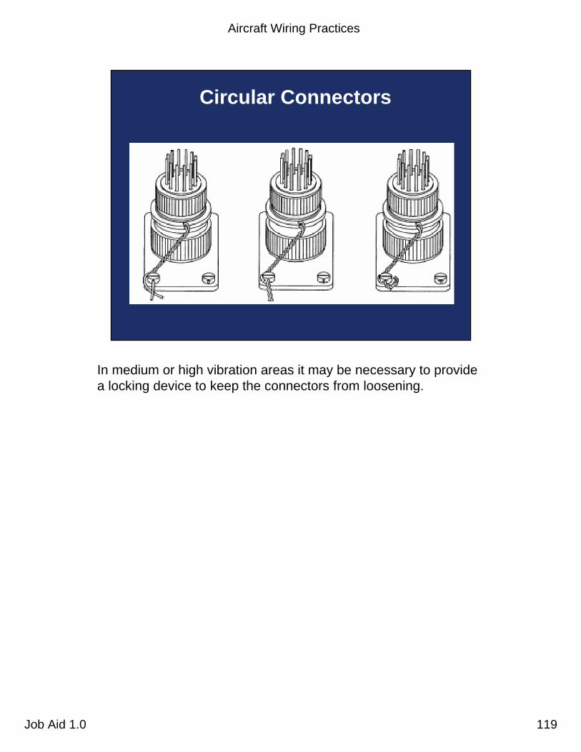
Aircraft Wiring Practices
Job Aid 1.0 119
Circular Connectors
In medium or high vibration areas it may be necessary to providea locking device to keep the connectors from loosening.

Aircraft Wiring Practices
Job Aid 1.0 120
Improper Lock Wire Installation
This slide shows a lock wire improperly installed. The lock wire is installed on the "loosening” side of the connector; it should be on the “lightening” side.
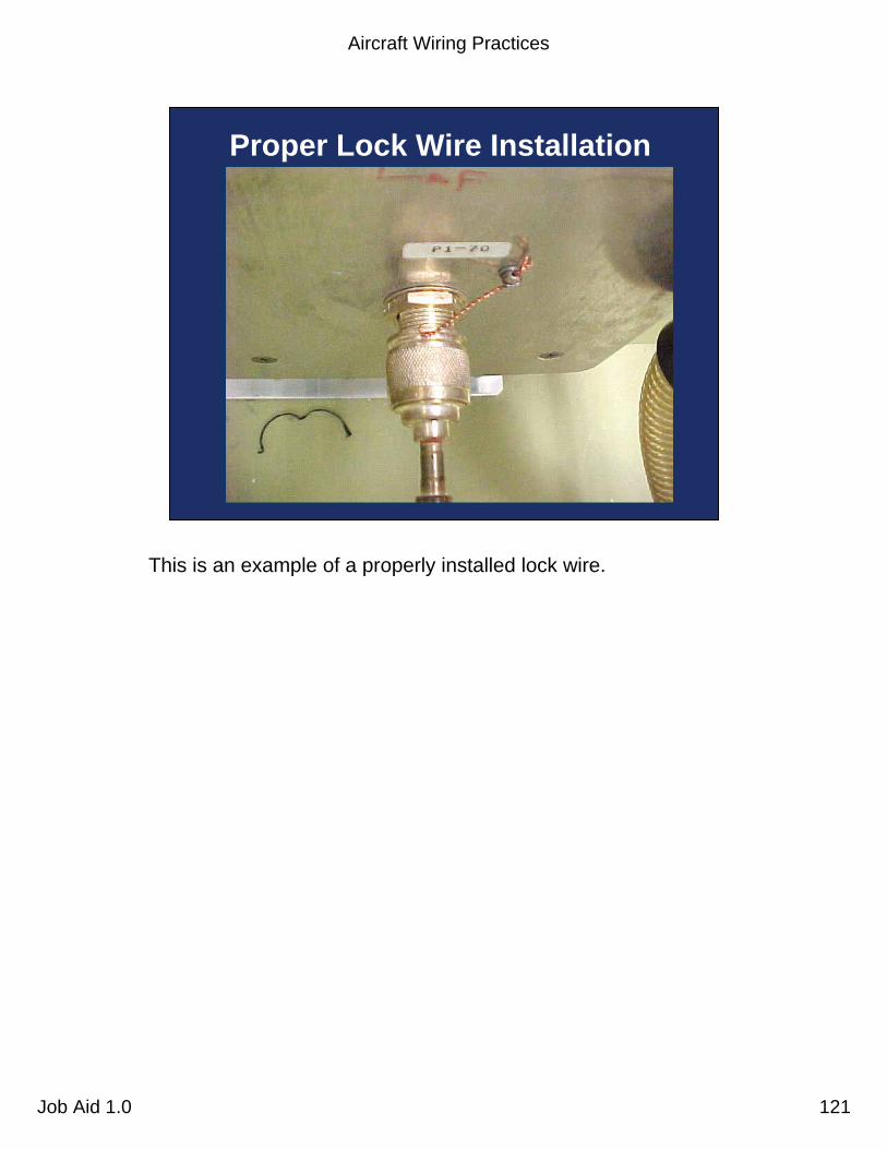
Aircraft Wiring Practices
Job Aid 1.0 121
Proper Lock Wire Installation
This is an example of a properly installed lock wire.
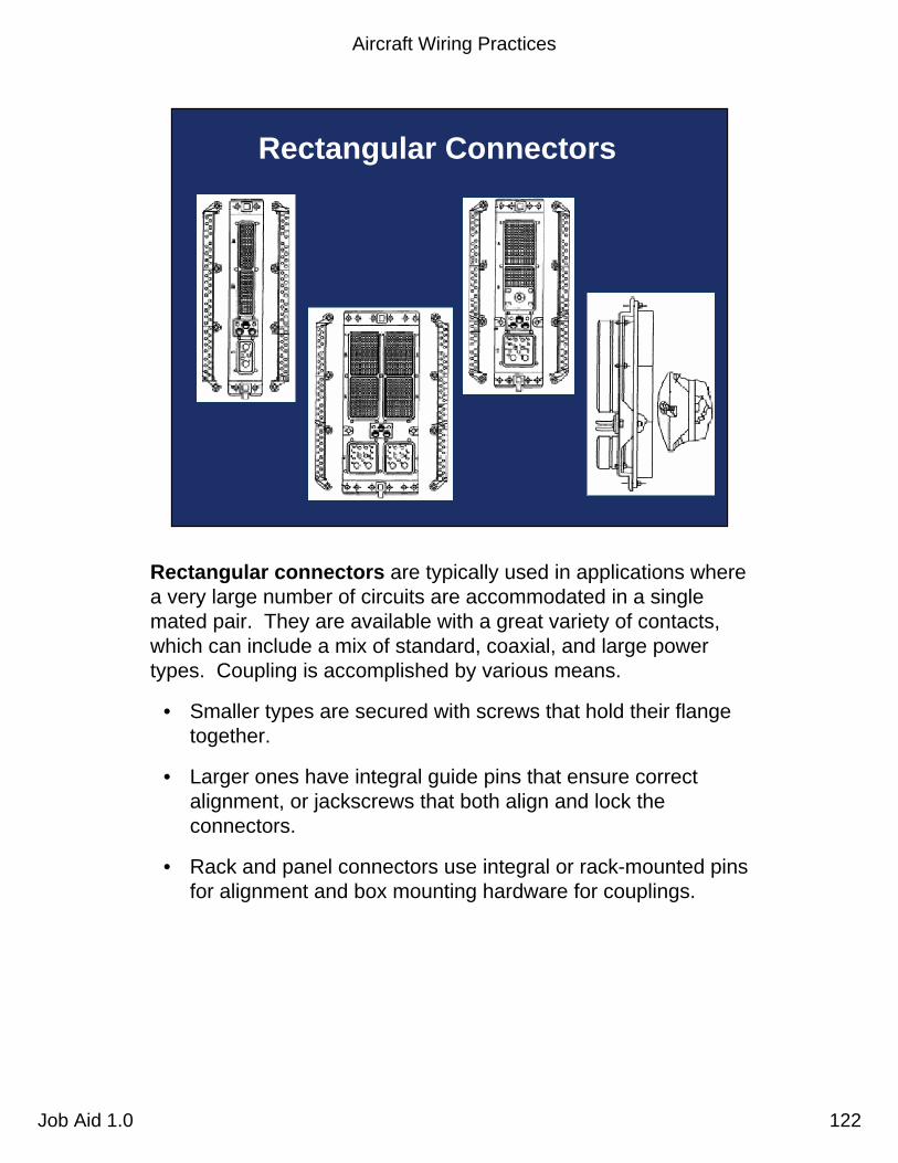
Aircraft Wiring Practices
Job Aid 1.0 122
Rectangular Connectors
Rectangular connectors are typically used in applications where a very large number of circuits are accommodated in a single mated pair. They are available with a great variety of contacts, which can include a mix of standard, coaxial, and large power types. Coupling is accomplished by various means.
• Smaller types are secured with screws that hold their flange together.
• Larger ones have integral guide pins that ensure correct alignment, or jackscrews that both align and lock the connectors.
• Rack and panel connectors use integral or rack-mounted pins for alignment and box mounting hardware for couplings.

Aircraft Wiring Practices
Job Aid 1.0 123
Module Blocks (Terminal Blocks)
Module blocks accept crimped contacts similar to those on connectors. Some use internal busing to provide a variety of circuit arrangements.
• Module blocks (or terminal blocks) are useful where a number of wires are connected for power or signal distribution. When used as grounding modules, they save and reduce hardware installation on the aircraft.
• Standardized modules are available with wire-end grommet seals for environmental applications and are track-mounted.

Aircraft Wiring Practices
Job Aid 1.0 124
View AUnacceptable
grommet
Terminal Block Grommet Distortion
A
View AAcceptable
wire
For complex wire breakouts that are terminated into terminal blocks, care must be taken to allow enough slack to prevent excessive forces from pulling the terminated wires that are inserted into the terminal block.
• This condition can lead to terminal block grommet distortion, which can lead to wire damage or a wire that will be pulled free from the terminal block.

Aircraft Wiring Practices
Job Aid 1.0 125
Grommet Distortion
Improper: grommet distortion due to tight wires; not enough slack
Proper: no excessive tension on wires;
enough slack to avoid grommet distortion

Aircraft Wiring Practices
Job Aid 1.0 126
Federal AviationAdministration 126Aircraft Wiring Practices Job Aid 1.0
Conduits
• Purpose– Mechanical protection of wires and cables– Grouping and routing wires
• Standards– Absence of abrasion at end fittings– Proper clamping– Adequate drain holes free of obstructions– Minimized damage from moving objects– Proper bend radii
Purpose. Primarily the purpose of conduits is for mechanical protection of cables or wires. Secondarily, conduits are used for environmental protection and grouping of wires by signal type. Standards
• Conduit should be inspected for: proper end fittings; absence of abrasion at the end fittings; proper clamping; distortion; adequate drain holes that are free of dirt, grease, or other obstructions; and freedom from abrasion or damage due to moving objects, such as aircraft control cables or shifting cargo.
• Size of conduit. Conduit size should be selected for a specific wire bundle application to allow for ease in maintenance, and possible future circuit expansion, by specifying the conduit inner diameter (I.D.) about 25 percent larger than the maximum diameter of the wire bundle.
• Conduit fittings. Wire is vulnerable to abrasion at conduit ends. Suitable fittings should be affixed to conduit ends in such a manner that a smooth surface comes in contact with the wire. When fittings are not used, the end of the conduit should be flared to prevent wire insulation damage. Conduit should be supported by use of clamps along the conduit run.

Aircraft Wiring Practices
Job Aid 1.0 127
Federal AviationAdministration 127Aircraft Wiring Practices Job Aid 1.0
Conduit Installation Guidelines
• Do not locate conduit where service or maintenance personnel might use as handhold or footstep
• Provide inspectable drain holes at the lowest point in conduit run — remove drilling burrs carefully
• Support conduit to prevent chafing against structure and avoid stressing end fittings
Conduit installation. Conduit problems can be avoided by following these guidelines:
• Do not locate conduit where service or maintenance personnel might use it as a handhold or footstep.
• Provide inspectable drain holes at the lowest point in a conduit run. Drilling burrs should be carefully removed.
• Support conduit to prevent chafing against structure and to avoid stressing its end fittings.
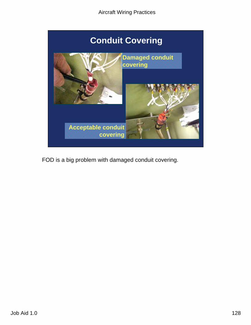
Aircraft Wiring Practices
Job Aid 1.0 128
Conduit Covering
Damaged conduit covering
Acceptable conduit covering
FOD is a big problem with damaged conduit covering.

Aircraft Wiring Practices
Job Aid 1.0 129
08/15/99
13
Federal AviationAdministration 129Aircraft Wiring Practices Job Aid 1.0
– Flame resistant– Mechanical strength– Smoke emission– Fluid resistance– Heat distortion
Wire Insulation Selection
• Chose characteristics based on environment– Abrasion resistance– Arc resistance– Corrosion resistance– Cut-through strength– Dielectric strength
Environmental characteristics. As shown in this slide, there are many insulation materials and combinations used in aircraft wiring. Wire insulation characteristic should be chosen based on meeting FAA flame resistance and smoke emission requirements (25.869) and the environment in which the wire is to be installed.
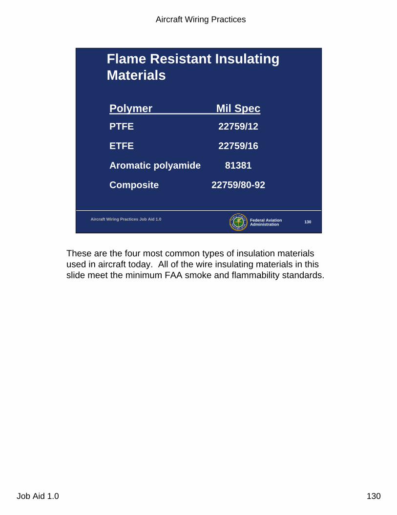
Aircraft Wiring Practices
Job Aid 1.0 130
Federal AviationAdministration 130Aircraft Wiring Practices Job Aid 1.0
Flame Resistant Insulating Materials
Polymer Mil SpecPTFE 22759/12
ETFE 22759/16
Aromatic polyamide 81381
Composite 22759/80-92
These are the four most common types of insulation materials used in aircraft today. All of the wire insulating materials in this slide meet the minimum FAA smoke and flammability standards.
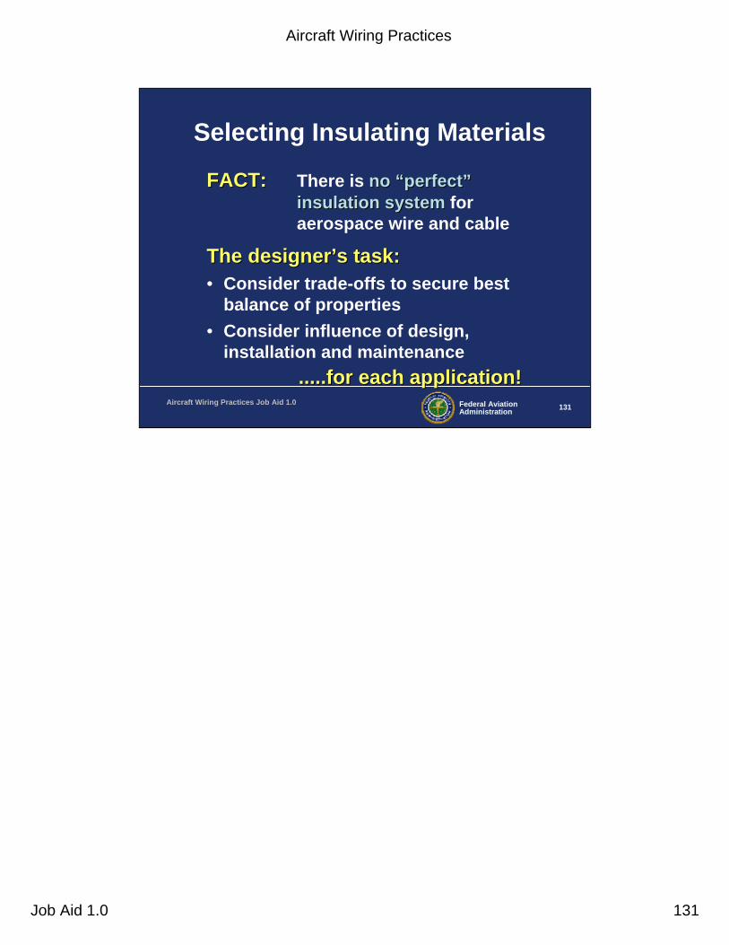
Aircraft Wiring Practices
Job Aid 1.0 131
Federal AviationAdministration 131Aircraft Wiring Practices Job Aid 1.0
Selecting Insulating Materials
FACT:FACT: There is nono ““perfectperfect””insulation systeminsulation system for aerospace wire and cable
The designerThe designer’’s task:s task:• Consider trade-offs to secure best
balance of properties• Consider influence of design,
installation and maintenance.....for each application!.....for each application!

Aircraft Wiring Practices
Job Aid 1.0 132
Federal AviationAdministration 132Aircraft Wiring Practices Job Aid 1.0
How to Choose Wire Insulation
• Seek the best balance of properties:– Electrical– Mechanical– Chemical– Thermal
PlusPlus– Nonflammability and low smoke

Aircraft Wiring Practices
Job Aid 1.0 133
Comparative Properties of Wire Insulation SystemsComparative Properties of Wire Insulation Systems
Relative Ranking 1 2 3 4Weight PI ETFE COMP PTFETemperature PTFE COMP PI ETFEAbrasion resistance PI ETFE COMP PTFECut-through resistance PI COMP ETFE PTFEChemical resistance PTFE ETFE COMP PIFlammability PTFE COMP PI ETFESmoke generation PI COMP PTFE ETFEFlexibility PTFE ETFE COMP PICreep (at temperature) PI COMP PTFE ETFEArc propagation resistance PTFE ETFE COMP PI
Most desirable Least
PI [Aromatic Polyimide (KAPTON)] - (mil spec 81381) • Desirable properties: abrasion/cut-through, low-smoke/non-flame,
weight/space• Limitations: arc-track resistance, flexibility
ETFE (TEFZEL) - (mil spec 22759/16) • Desirable properties: chemical resistance, abrasion resistance,
ease of use• Limitations: high temperature, cut-through, thermal rating (150°C)
Composite (TKT) - (mil spec 22759/80-92) • Desirable properties: high temperature rating (260°C), cut-through
resistance, arc-track resistance• Limitations: outer layer scuffing
PTFE (TEFLON) - (mil spec 22759/12) • Desirable properties: 260°C thermal rating, low-smoke/non-flame,
high flexibility• Limitations: Cut-through resistance, “creep” at temperature

Aircraft Wiring Practices
Job Aid 1.0 134
Federal AviationAdministration 134Aircraft Wiring Practices Job Aid 1.0
Conclusion on Insulation
• Aircraft designer can choose among many polymeric materials
• Physical and chemical properties are equally important
• Safest system combines “balance of properties” with inherent flame and/or smoke resistance
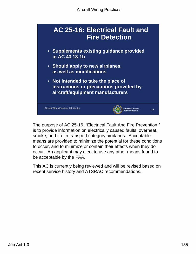
Aircraft Wiring Practices
Job Aid 1.0 135
Federal AviationAdministration 135Aircraft Wiring Practices Job Aid 1.0
AC 25-16: Electrical Fault and Fire Detection
• Supplements existing guidance provided in AC 43.13-1b
• Should apply to new airplanes, as well as modifications
• Not intended to take the place of instructions or precautions provided by aircraft/equipment manufacturers
The purpose of AC 25-16, “Electrical Fault And Fire Prevention,”is to provide information on electrically caused faults, overheat, smoke, and fire in transport category airplanes. Acceptable means are provided to minimize the potential for these conditions to occur, and to minimize or contain their effects when they do occur. An applicant may elect to use any other means found to be acceptable by the FAA.
This AC is currently being reviewed and will be revised based onrecent service history and ATSRAC recommendations.

Aircraft Wiring Practices
Job Aid 1.0 136
Federal AviationAdministration 136Aircraft Wiring Practices Job Aid 1.0
AC 25-16: Circuit Protection Devices (CPDs)
• Circuit breaker resets– Can significantly worsen an arcing event
– Crew should only attempt to reset a tripped breaker if function is absolutely required
• Information should be provided in AFMs or AFM revisions or supplements
Information should be provided in FAA-approved Airplane Flight Manuals (AFM) or AFM revisions or supplements that the crew should only attempt to restore an automatically-disconnected power source or reset or replace an automatically-disconnected circuit protection device (CPD) that affects flight operations or safety.
• NOTE: It is strongly recommended that circuit breakers for non-essential systems not be reset in flight.
Most transport OAMs and operators are revising their procedures to not allow circuit breaker resets in flight following a circuit breaker trip event. Service history has shown that resetting a circuit breaker can greatly influence the degree of arcing damage to the wiring. Each successive attempt to restore an automatically-disconnected CPD, can result in progressively worsening effects from arcing.

Aircraft Wiring Practices
Job Aid 1.0 137
Arc Tracking and Insulation Flashover(Caused by multiple circuit breaker resets)
This picture shows the effects of multiple circuit breaker resets. In this case, the original arcing event was not able to be determined due to the severe secondary damage following the circuit breaker resets.
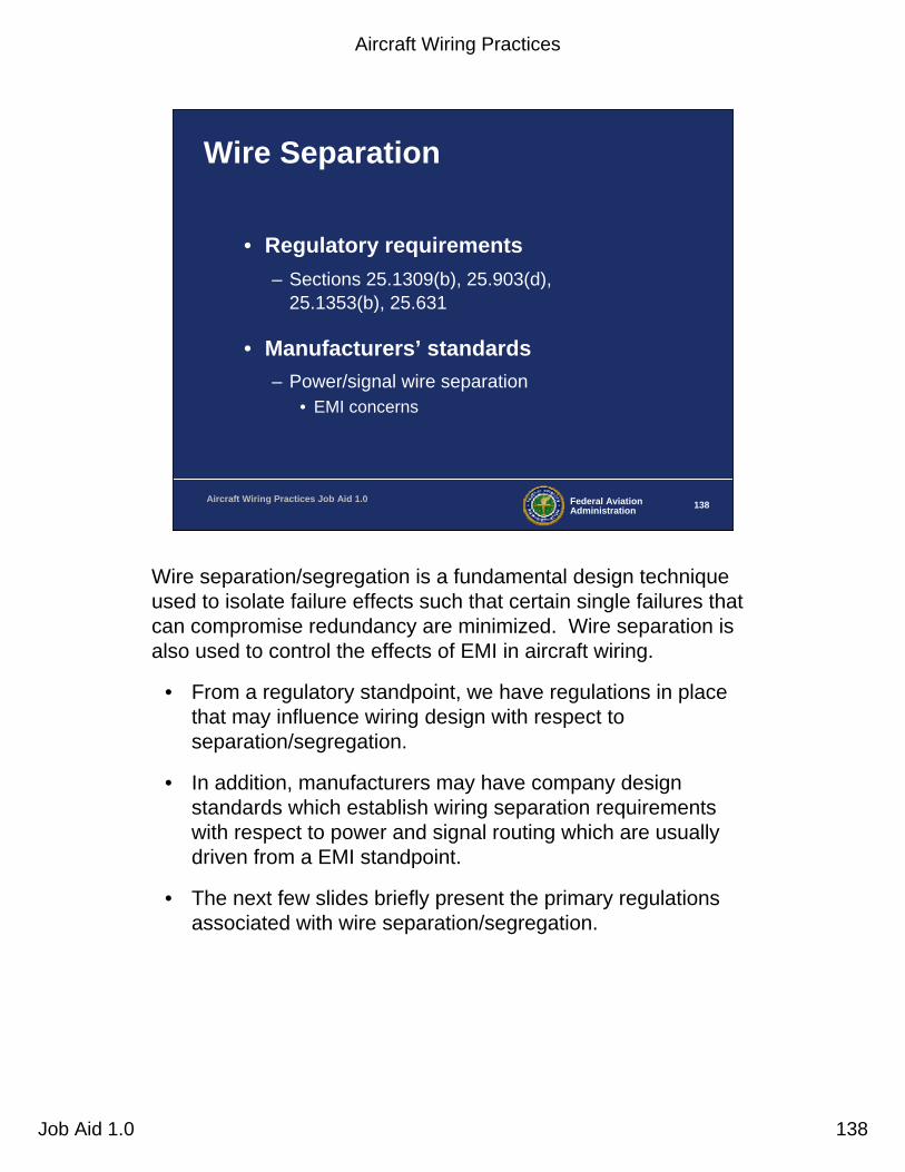
Aircraft Wiring Practices
Job Aid 1.0 138
Federal AviationAdministration 138Aircraft Wiring Practices Job Aid 1.0
Wire Separation
• Regulatory requirements– Sections 25.1309(b), 25.903(d),
25.1353(b), 25.631
• Manufacturers’ standards– Power/signal wire separation
• EMI concerns
Wire separation/segregation is a fundamental design technique used to isolate failure effects such that certain single failures that can compromise redundancy are minimized. Wire separation is also used to control the effects of EMI in aircraft wiring.
• From a regulatory standpoint, we have regulations in place that may influence wiring design with respect to separation/segregation.
• In addition, manufacturers may have company design standards which establish wiring separation requirements with respect to power and signal routing which are usually driven from a EMI standpoint.
• The next few slides briefly present the primary regulations associated with wire separation/segregation.

Aircraft Wiring Practices
Job Aid 1.0 139
Federal AviationAdministration 139Aircraft Wiring Practices Job Aid 1.0
Wire Separation from a 25.1309(b) Standpoint
• No single failure shall prevent continued safe flight and landing– Consider possible modes of failure including
external events, e.g. wire bundle failure or damage
•• Common Cause AnalysisCommon Cause Analysis may indicate need for separation requirements
•• Zonal AnalysisZonal Analysis will verify requirements– E.g.: auto-land wiring, inertial reference unit (IRU)
wiring
According to the requirements of 25.1309(b), a catastrophic failure condition must not result from the failure of a single component, part, or element of a system. A single failure includes any set of failures that cannot be shown to be independent from each other. Failure-containment techniques available to establish independence may include partitioning, separation, and isolation.Common cause failure considerations. An analysis should consider the application of the fail-safe design concept and give special attention to ensure the effective use of design techniques that would prevent single failures or other events from damaging or otherwise adversely affecting more than one redundant system channel, more than one system performing operationally similar functions, or any system and an associated safeguard. When considering such common-cause failures or other events, consequential or cascading effects should be taken into account. Some examples of such potential common cause failures or other events would include:
• Rapid release of energy from concentrated sources such as uncontained failures of rotating parts (other than engines and propellers) or pressure vessels.
• Pressure differentials.• Non-catastrophic structural failures.• Loss of environmental conditioning.• Disconnection of more than one subsystem or component by overtemperature protection devices.• Contamination by fluids.• Damage from localized fires.• Loss of power supply or return (e.g. mechanical damage or deterioration of connections).• Excessive voltage.• Physical or environmental interactions among parts, errors, or events external to the system or to the airplane.
ARP 4761 contains industry accepted methods of conducting Common Cause Analysis. If you want to know more about ARP 4761, there is a System Safety Assessment Video and Self-study Guide available through your Directorate training manager.For verifying wiring separation, an aircraft Zonal Analysis, along with wiring related aspects of Particular Risks Analysis and Common Mode Analysis will verify wiring separation requirements.

Aircraft Wiring Practices
Job Aid 1.0 140
Federal AviationAdministration 140Aircraft Wiring Practices Job Aid 1.0
Wire Separation from a 25.903(d) Standpoint
• Turbine engine installations: Minimize hazards in case of rotor failure– Project debris path through aircraft
• Determine vulnerable areas where redundancy can be violated
– May need to separate certain critical systems components including wiring, e.g., electrical power feeders, fly-by-wire control paths
Recently, the JAA requirements with respect to uncontained engine failure assessment were harmonized with the FAA and were issued as AC 20-128A. AC 20-128A provides specific methods for demonstrating compliance with 25.903(d).
• The primary requirement relative to uncontained engine failure is to use practical design precautions to minimize the risk of catastrophic damage due to non-contained engine rotor debris.
- An element of difficulty is introduced when the fuselage diameter is exposed to the relatively large diameter fan rotors of modern high-bypass-ratio turbofan engines.
- Separation of critical systems wiring may be a primary factor in establishing compliance.
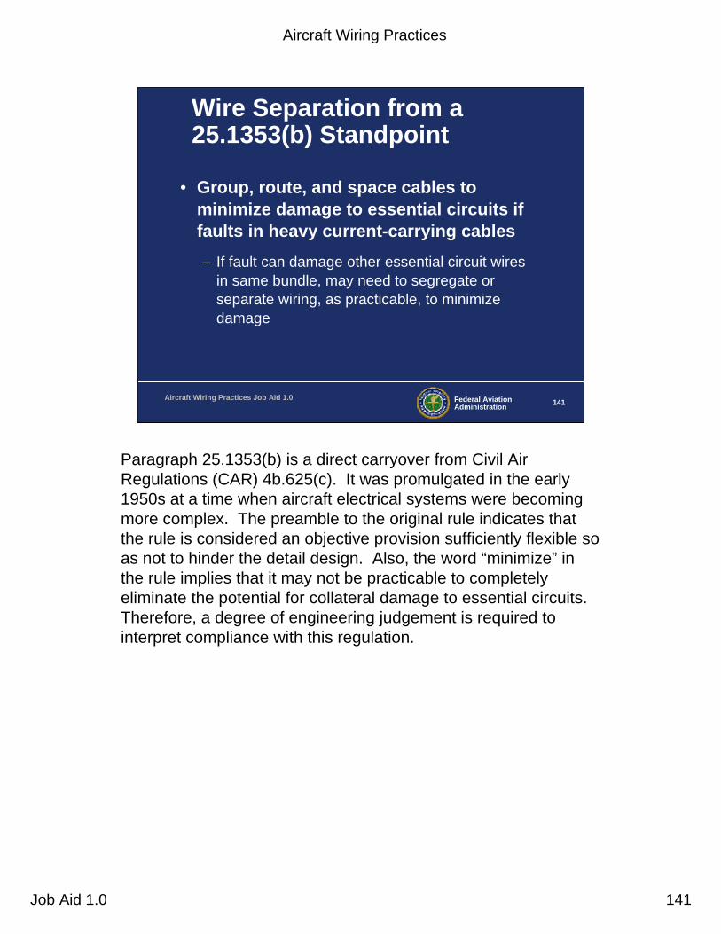
Aircraft Wiring Practices
Job Aid 1.0 141
Federal AviationAdministration 141Aircraft Wiring Practices Job Aid 1.0
Wire Separation from a 25.1353(b) Standpoint
• Group, route, and space cables to minimize damage to essential circuits if faults in heavy current-carrying cables– If fault can damage other essential circuit wires
in same bundle, may need to segregate or separate wiring, as practicable, to minimize damage
Paragraph 25.1353(b) is a direct carryover from Civil Air Regulations (CAR) 4b.625(c). It was promulgated in the early 1950s at a time when aircraft electrical systems were becoming more complex. The preamble to the original rule indicates that the rule is considered an objective provision sufficiently flexible so as not to hinder the detail design. Also, the word “minimize” in the rule implies that it may not be practicable to completely eliminate the potential for collateral damage to essential circuits. Therefore, a degree of engineering judgement is required to interpret compliance with this regulation.

Aircraft Wiring Practices
Job Aid 1.0 142
Federal AviationAdministration 142Aircraft Wiring Practices Job Aid 1.0
Wire Separation from a 25.631 Standpoint
• Continued safe flight and landing after impact with 8-lb. bird– Consider protected location of control system
elements• If impact can effect redundant system wiring, may
need additional physical protection of wiring or wiring separation
– E.g.: Impact brow area above windshield could affect electrical power redundancy in some aircraft
The birdstrike impact areas of the aircraft should be assessed for their structural strength by test and/or approved analysis methods. Any penetrations or deformations of the aircraft structure should be further analyzed for the effect of systems installation.
• For example, if a birdstrike test on the cockpit overhead eyebrow area indicates an elastic deformation of 2 inches, then the deformation should be analyzed or superimposed on whatever systems may be installed in the overhead cockpit area at that particular deformation location. In many aircraft,electrical and/or hydraulic control panels and associated wiring are installed in the overhead cockpit area (this is a relatively small area).
• The effect of the birdstrike can be analyzed with respect to a common cause failure standpoint. Wire separation aspects of the design may be an element in compliance to this rule.

Aircraft Wiring Practices
Job Aid 1.0 143
Federal AviationAdministration 143Aircraft Wiring Practices Job Aid 1.0
Post-TC Wire Separation
• Maintain wire separation requirements throughout life of aircraft– STC applicants may not be aware of separation or
other wiring requirements (i.e., do not have needed design data)
– Wiring added or moved as part of the STC should satisfy original separation requirements and wiring standards
– FAA draft policy letter in development
A potential problem with STCs and other modifications to transport aircraft is that the applicants may not analyze their proposed wiring installation with respect to the OAM’s wiring separation requirements and other OAM wiring design standards. Added or modified wiring could possibly defeat the OAM wiring philosophy and create unsafe conditions. The FAA is currently in the process of drafting policy. The draft policy letter will clarify FAA’s policy to require that type design data packages for multiple approvals include the following:
• A drawing package that completely defines the configuration, material, and production processes necessary to produce each part in accordance with the certification basis of the product.
• Any specifications referenced by the required drawings.Drawings that completely define the location, installation, and routing, as appropriate, of all equipment in accordance with the certification basis of the product.
• Examples of such equipment are wire bundles, plumbing, control cables, and other system interconnecting hardware.
• If the modification being approved is a change to a type certificated product, the modification must be equivalent to and compatible with the original type design standards.
Instructions for Continued Airworthiness (ICA) prepared in accordance with the requirements of 21.50 (“Instructions for continued airworthiness and manufacturer’s maintenance manuals having airworthiness limitations sections”).
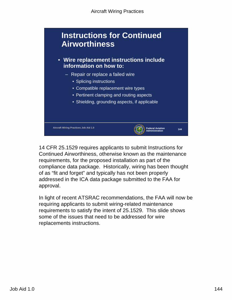
Aircraft Wiring Practices
Job Aid 1.0 144
Federal AviationAdministration 144Aircraft Wiring Practices Job Aid 1.0
Instructions for Continued Airworthiness
• Wire replacement instructions include information on how to:– Repair or replace a failed wire
• Splicing instructions• Compatible replacement wire types• Pertinent clamping and routing aspects• Shielding, grounding aspects, if applicable
14 CFR 25.1529 requires applicants to submit Instructions for Continued Airworthiness, otherwise known as the maintenance requirements, for the proposed installation as part of the compliance data package. Historically, wiring has been thought of as “fit and forget” and typically has not been properly addressed in the ICA data package submitted to the FAA for approval.
In light of recent ATSRAC recommendations, the FAA will now be requiring applicants to submit wiring-related maintenance requirements to satisfy the intent of 25.1529. This slide showssome of the issues that need to be addressed for wire replacements instructions.

Aircraft Wiring Practices
Job Aid 1.0 145
Federal AviationAdministration 145Aircraft Wiring Practices Job Aid 1.0
ICA, cont.
• ATSRAC recommendations– Clean-as-you-go philosophy
– Wiring general visual inspections (WGVI)
– Non-destructive testing (NDT) equipment
– Preemptive repair of splices and/or replacement of wire
Aircraft Wiring Practices
Job Aid 1.0 146
Federal AviationAdministration 146Aircraft Wiring Practices Job Aid 1.0
Clean-as-you-go Philosophy
• Keep wiring clean throughout life of aircraft– Protect wiring during routine maintenance
– Clean wiring periodically (vacuum, light brushing, etc.) during heavy maintenance when hidden areas exposed
CAUTION! For wiring with extremely heavy accumulation of dirt, lint, and other FOD where cleaning cannot be safely accomplished, judgement must be used since more damage may occur during a vigorous cleaning process than if the dirt were allowed to accumulate. Wire replacement should be considered in these cases.

Aircraft Wiring Practices
Job Aid 1.0 147
Federal AviationAdministration 147Aircraft Wiring Practices Job Aid 1.0
WGVI Focus Areas
• Clamping points– Improper installation
– Clamp/wire damage
– Clamp cushion migration
• Connectors– Worn seals– Loose connectors– Lack of strain relief– Drip loops– Tight wire bends
Clamping points - Wire chafing is aggravated by loose clamps, damaged clamps, clamp cushion migration, or improper clamp installations.
Connectors - Worn environmental seals, loose connectors, excessive corrosion, missing seal plugs, missing dummy contacts, or lack of strain relief on connector grommets can compromise connector integrity and allow contamination to enter the connector, leading to corrosion or grommet degradation. Drip loops should be maintained when connectors are below the level of the harness and tight bends at connectors should be avoided or corrected.

Aircraft Wiring Practices
Job Aid 1.0 148
Federal AviationAdministration 148Aircraft Wiring Practices Job Aid 1.0
WGVI Focus Areas, cont.
• Terminations– Lugs/splices
• Backshells– Improper build-up– Lack of strain relief
• Damaged sleeving and conduits
• Grounding points– Tightness– Cleanliness– Corrosion
Terminations - Terminal lugs and splices are susceptible to mechanical damage, corrosion, heat damage and chemical contamination. Also, the build up and nut torque on large-gauge wire studs is critical to their performance.
Backshells - Wires may break at backshells, due to excessive flexing, lack of strain relief, or improper build-up. Loss of backshell bonding may also occur due to these and other factors.
Damaged sleeving and conduits - Damage to sleeving and conduits, if not corrected, will often lead to wire damage.
Grounding points - Grounding points should be checked for security (i.e. tightness), condition of the termination, cleanliness, and corrosion. Any grounding points that are corroded or have lost their protective coating should be repaired.

Aircraft Wiring Practices
Job Aid 1.0 149
Federal AviationAdministration 149Aircraft Wiring Practices Job Aid 1.0
Wiring Inspection Locations
• Wings– Exposed wiring on leading/trailing edges during
flap/slat operation
• Engine/APUs/pylon/nacelle– Heat/vibration/chemical contamination– High maintenance area
• Landing gear/wheel wells– Environmental/vibration/chemical
Wiring inspection locations. Available data indicate that the locations shown on the slide should receive special attention in an operator’s wiring inspection program.
Wings - The wing leading and trailing edges are areas that experience difficult environments for wiring installations. The wing leading and trailing edge wiring is exposed on some aircraft models whenever the flaps or slats are extended. Other potential damage sources include slat torque shafts and bleed air ducts.
Engine, pylon, and nacelle area - These areas experience high vibration, heat, frequent maintenance, and are susceptible to chemical contamination.
APU - Like the engine/nacelle area, the APU is susceptible to high vibration, heat, frequent maintenance, and chemical contamination.
Landing gear and wheel wells - This area is exposed to severe external environmental conditions in addition to vibration and chemical contamination.
Aircraft Wiring Practices
Job Aid 1.0 150
Federal AviationAdministration 150Aircraft Wiring Practices Job Aid 1.0
Wiring Inspection Locations, cont.
• Electrical panels/line replacement units (LRU)– High density areas– High maintenance activity– Prone to broken/damaged wires
• Batteries– Chemical contamination/corrosion
• Power feeders– Feeder terminations– Signs of heat distress
Electrical panels and line replaceable units (LRUs) - Panel wiring is particularly prone to broken wires and damaged insulation when these high density areas are disturbed during troubleshooting activities, major modifications, and refurbishment. One repair facility has found that wire damage was minimized by tying wiring to wooden dowels. This reduced wire disturbance during modification. It is also recommended to remove entire disconnect brackets, when possible, instead of removing individual receptacles.
Batteries - Wires and wiring hardware in the vicinity of all aircraft batteries should be inspected for corrosion and discoloration. Discolored wires should be inspected for serviceability. Corroded wires and/or wiring hardware should be replaced.
Power feeders - Operators may find it advantageous to inspect splices and terminations for signs of overheating and security. If any signs of overheating are seen, the splice or termination should be replaced. This applies to galley power feeders, in addition to the main and APU generator power feeders. The desirability of periodically retorquing power feeder terminations should be evaluated.
Aircraft Wiring Practices
Job Aid 1.0 151
Federal AviationAdministration 151Aircraft Wiring Practices Job Aid 1.0
Wiring Inspection Locations, cont.
• Under galleys and lavatories– Susceptible to fluid contamination– Fluid drainage provisions
• Cargo bay/underfloor area– High maintenance activity
• Surfaces, controls, doors– Moving and bending wire harnesses
• Near access panels– Prone to accidental damage
Under galleys and lavatories - Areas under the galleys, lavatories and other liquid containers are particularly susceptible to contamination from coffee, food, water, soft drinks and lavatory fluids, etc. Fluid drain provisions should be periodically inspected and repaired as necessary.
Cargo bay/under floor - Cargo can damage wiring. Damage to wiring in the cargo bay under floor can occur due to maintenanceactivities in the area.
Surfaces, controls, and doors - Moving or bending harnesses should be inspected at these locations.
Access panels - Harnesses near access panels may receive accidental damage and should have special emphasis inspections.

Aircraft Wiring Practices
Job Aid 1.0 152
Federal AviationAdministration 152Aircraft Wiring Practices Job Aid 1.0
Nondestructive Wire Testing Methods
• Still in the R & D phase
• Can detect wiring faults “in-situ” i.e., with wiring still installed
• Can aid in isolating wiring faults during the maintenance process
Nondestructive testing (NDT) is not a mature technology at this point. The FAA is currently working with industry to develop these technologies. NDT can detect wiring faults “in-situ” (with wiring still installed) and can be a tremendous aid in isolatingwiring faults during the maintenance process. There will be more information on this topic as this promising technology matures.
Aircraft Wiring Practices
Job Aid 1.0 153
Federal AviationAdministration 153Aircraft Wiring Practices Job Aid 1.0
Preemptive wire splice repair and/or wire replacement
• Certain wire types and splice types may need periodic repair or replacement depending on installation environment
• Maintenance procedures should address this aspect, as required
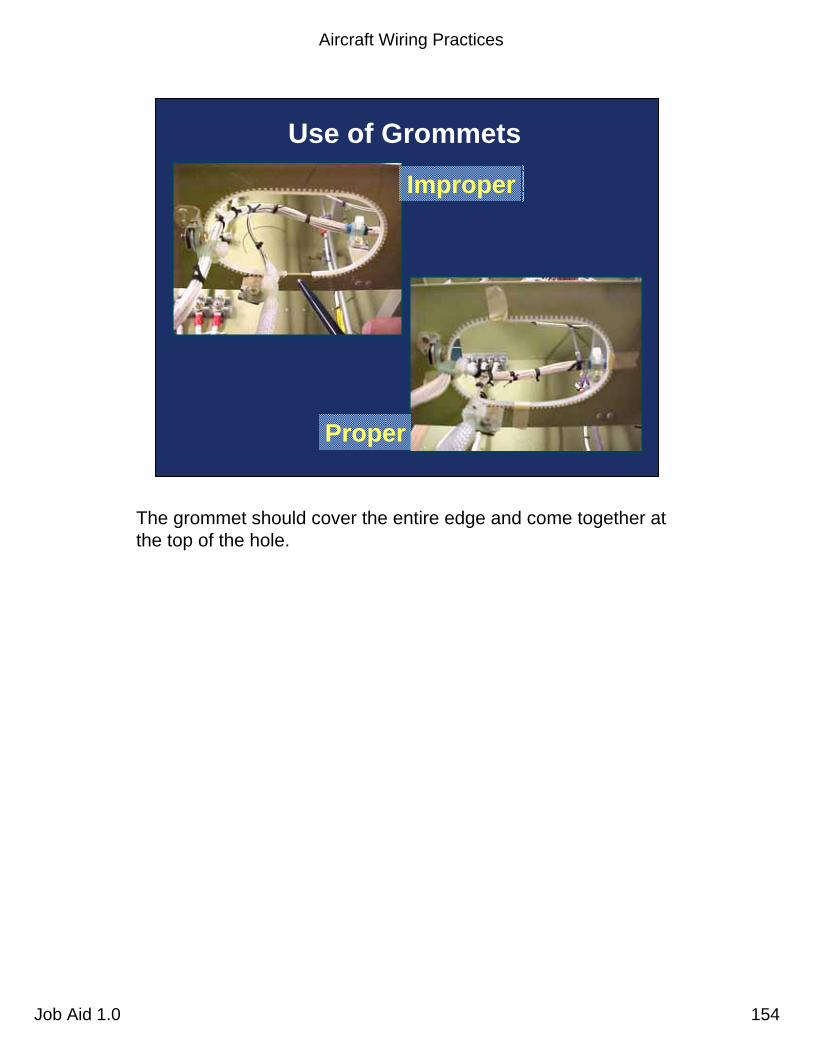
Aircraft Wiring Practices
Job Aid 1.0 154
Use of Grommets
Improper
Proper
The grommet should cover the entire edge and come together at the top of the hole.
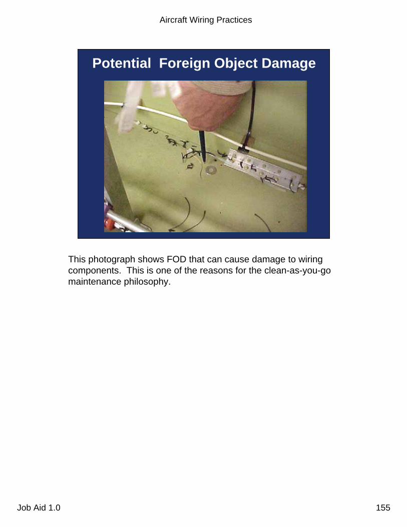
Aircraft Wiring Practices
Job Aid 1.0 155
Potential Foreign Object Damage
This photograph shows FOD that can cause damage to wiring components. This is one of the reasons for the clean-as-you-go maintenance philosophy.
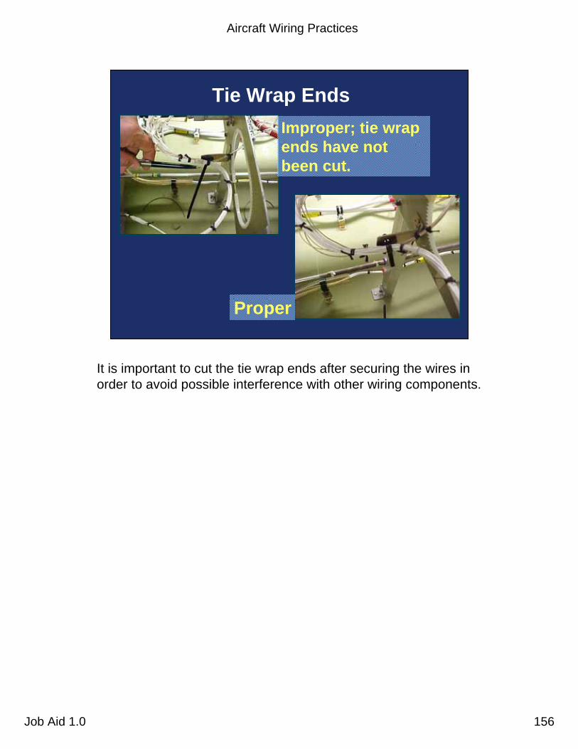
Aircraft Wiring Practices
Job Aid 1.0 156
Tie Wrap EndsImproper; tie wrap ends have not been cut.
Proper
It is important to cut the tie wrap ends after securing the wires in order to avoid possible interference with other wiring components.

Aircraft Wiring Practices
Job Aid 1.0 157
Clamp Cushion
Damaged clamp cushion
Undamaged clamp cushion
Damaged clamp cushions can cause wire damage that can lead to arcing.

Aircraft Wiring Practices
Job Aid 1.0 158
Sleeving Installation
Improperly installed sleeving
Properly installed sleeving
Protective sleeving should overlap at least 30% to ensure 100% coverage of the wire bundle.
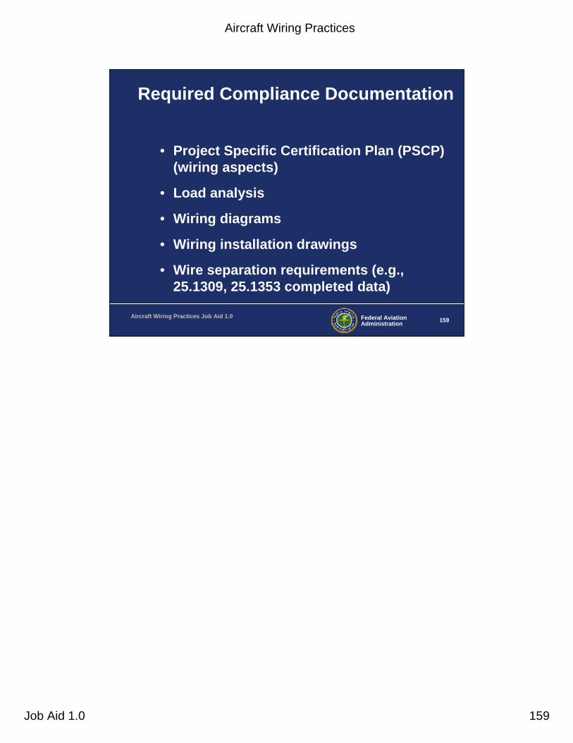
Aircraft Wiring Practices
Job Aid 1.0 159
Federal AviationAdministration 159Aircraft Wiring Practices Job Aid 1.0
Required Compliance Documentation
• Project Specific Certification Plan (PSCP) (wiring aspects)
• Load analysis
• Wiring diagrams
• Wiring installation drawings
• Wire separation requirements (e.g., 25.1309, 25.1353 completed data)

Aircraft Wiring Practices
Job Aid 1.0 160
Federal AviationAdministration 160Aircraft Wiring Practices Job Aid 1.0
Wiring Diagrams
• Wire selection– Gauge/breaker size– Insulation– Environmental considerations
• Connectors– Pin/socket ratings– Pin arrangement (best practices)– Environmental considerations
• Grounding
The engineer or designee should review the wiring diagrams and verify the following points. This information should be available on the wiring diagrams or referenced to the source.Wire selection - The wires must be sized properly and the circuit breaker sized to adequately protect the wire considering the ambient temperature of the environment. The circuit breaker protecting the wire should open before the circuit breaker protecting the upstream bus.
• The wire insulation and conductor plating must be suitable for the environment plus any further temperature rise due to dissipated power.
Connectors - Ensure that the connectors are suitable for the environment and the pins and sockets are properly rated to handle the power demands of the circuit.
• As we discussed earlier, pin arrangements should minimize the possibility of shorts between power, ground, and/or signals. Verify that separation requirements from the safety assessment process are addressed. Also, ensure unused pins are properly protected.
Grounding - Ensure circuits have proper grounding.

Aircraft Wiring Practices
Job Aid 1.0 161
Federal AviationAdministration 161Aircraft Wiring Practices Job Aid 1.0
Wiring Installation Drawings
• Clamps– Proper size, type, and material– Spaced appropriately for environment– Mounted correctly
• Feed throughs/pass throughs– Grommets used when necessary– Wire bundles properly supported
It is important to note that installation drawings generally do not provide the necessary detail to ensure proper clamping, routing, and termination of wiring for a given installation.
It is advisable for the engineer or designee to perform a first-of-a-model or first-of-a-design general wiring compliance inspection in addition to reviewing the wiring diagrams and wiring installation drawings. Consideration should be given to the complexity of the wiring system in determining the appropriate depth of the compliance inspection.
The engineer or designee should ensure that adequate installation drawings exist and review the drawings and perform the compliance inspection to verify the items noted on the following slides (which we discussed in detail earlier).
Clamps must be suitable with respect to size, type, and material. Also ensure that an adequate number of clamps are used to properly support the wire bundle. Clamps should be mounted correctly with proper orientation.
Feed throughs/pass throughs - Grommets suitable for the environment must be used when the wire bundle passes through pressure bulkhead, firewall, and other openings in the structure.
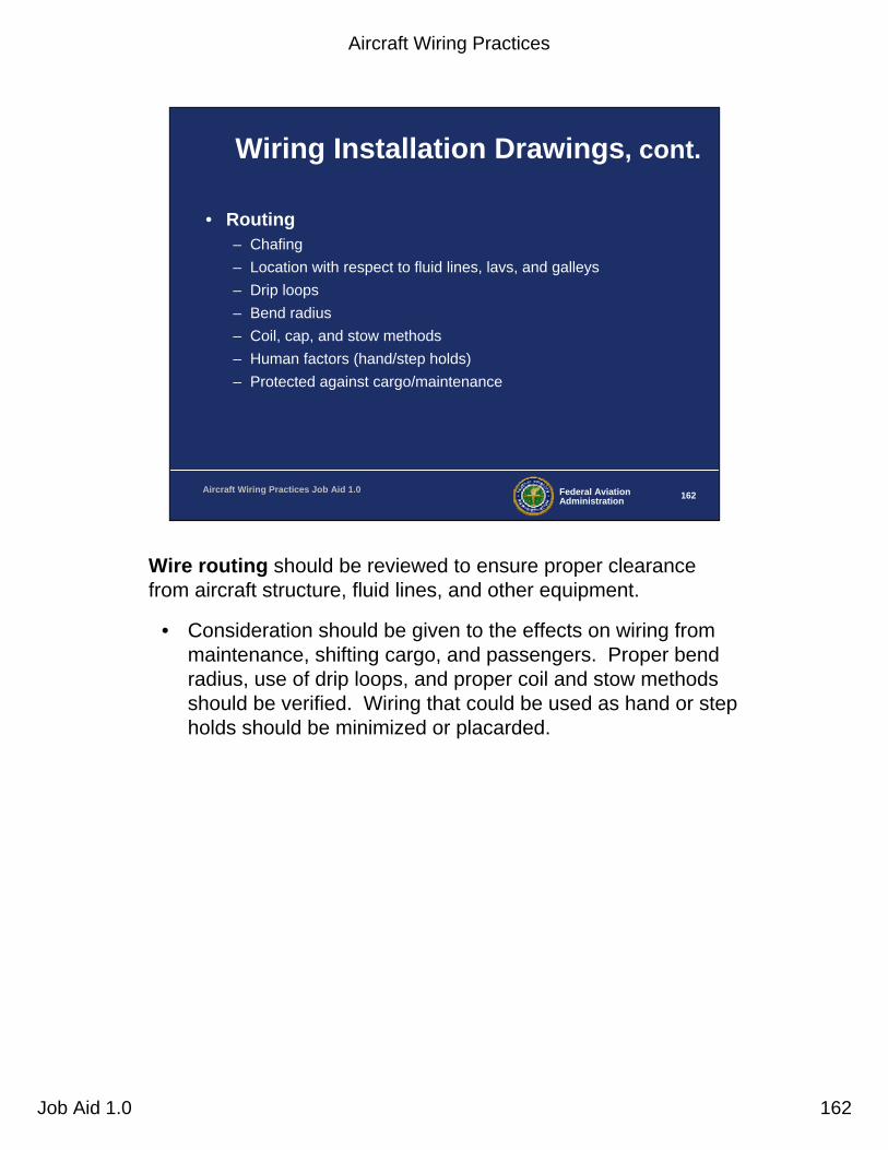
Aircraft Wiring Practices
Job Aid 1.0 162
Federal AviationAdministration 162Aircraft Wiring Practices Job Aid 1.0
Wiring Installation Drawings, cont.
• Routing– Chafing– Location with respect to fluid lines, lavs, and galleys– Drip loops– Bend radius– Coil, cap, and stow methods– Human factors (hand/step holds)– Protected against cargo/maintenance
Wire routing should be reviewed to ensure proper clearance from aircraft structure, fluid lines, and other equipment.
• Consideration should be given to the effects on wiring from maintenance, shifting cargo, and passengers. Proper bend radius, use of drip loops, and proper coil and stow methods should be verified. Wiring that could be used as hand or step holds should be minimized or placarded.
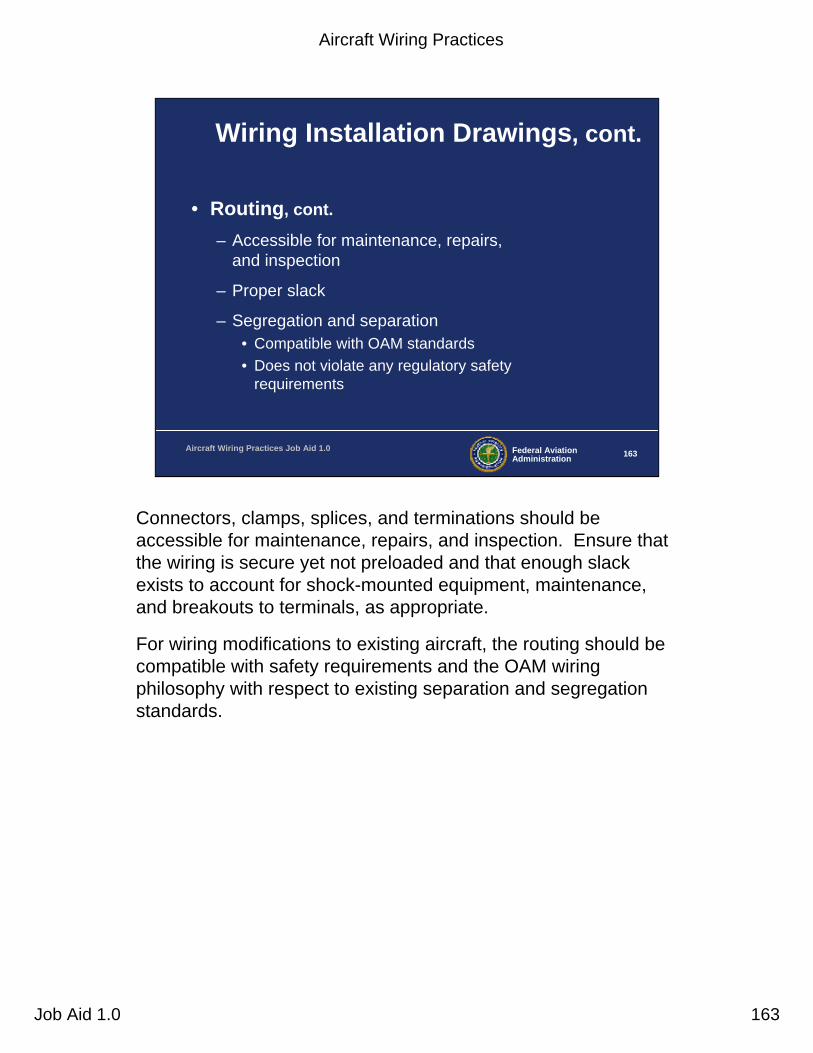
Aircraft Wiring Practices
Job Aid 1.0 163
Federal AviationAdministration 163Aircraft Wiring Practices Job Aid 1.0
Wiring Installation Drawings, cont.
• Routing, cont.
– Accessible for maintenance, repairs, and inspection
– Proper slack
– Segregation and separation• Compatible with OAM standards• Does not violate any regulatory safety
requirements
Connectors, clamps, splices, and terminations should be accessible for maintenance, repairs, and inspection. Ensure that the wiring is secure yet not preloaded and that enough slack exists to account for shock-mounted equipment, maintenance, and breakouts to terminals, as appropriate.
For wiring modifications to existing aircraft, the routing should be compatible with safety requirements and the OAM wiring philosophy with respect to existing separation and segregation standards.

Aircraft Wiring Practices
Job Aid 1.0 164
Federal AviationAdministration 164Aircraft Wiring Practices Job Aid 1.0
Wiring Installation Drawings, cont.
• Conduits– Sized properly
– Appropriate for environment
– Conduit ends are terminated
– Bend radius
– Drain holes
– Metallic - Are wires properly protected inside?
Conduits. Ensure that conduits are sized properly and appropriate for the environment.
• Pay particular attention to the conduit end points to ensure proper termination.
• Conduit bend radii should be suitable for both the conduit and wire bundle inside the conduit.
• Ensure that low spots in the conduit have drain holes that can be maintained and inspected.
• Also, ensure that wiring in metallic conduit is protected in a suitable manner.
Aircraft Wiring Practices
Job Aid 1.0 165
Federal AviationAdministration 165Aircraft Wiring Practices Job Aid 1.0
Aircraft Wiring Practices
• Brett Portwood: [email protected]
FAA Technical Specialist, Safety and Integration
Los Angeles ACO; ANM-130L(562)627-5350
• Massoud Sadeghi: [email protected]
Aging Systems Program Manager
Transport Airplane Directorate; ANM-114(425)227-2117