aircraft serious incident investigation …aircraft serious incident investigation report japan air...
TRANSCRIPT
AI2010-6
AIRCRAFT SERIOUS INCIDENT
INVESTIGATION REPORT
JAPAN AIR COMMUTER
J A 8 4 7 C
August 27, 2010
Japan Transport Safety Board
The investigation for this report was conducted by the Japan Transport Safety Board, JTSB, about
the aircraft serious incident of Japan Air Commuter Co., Ltd., Bombardier DHC-8-402 registration
JA847C in accordance with the act for the Establishment of the Japan Transport Safety Board and
Annex 13 to the Convention on the International Civil Aviation for the purpose of determining causes of
the aircraft serious incident and contributing to the prevention of accidents/incidents and not for the
purpose of blaming responsibility of the serious incident.
This English version of this report has been published and translated by the JTSB to make its
reading easier for English speaking people who are not familiar with Japanese. Although efforts are
made to translate as accurately as possible, only the Japanese version is authentic. If there is any
difference in the meaning of the texts between the Japanese and English versions, the text in the
Japanese version prevails.
Norihiro Goto
Chairman,
Japan Transport Safety Board
AIRCRAFT SERIOUS INCIDENT INVESTIGATION REPORT
JAPAN AIR COMMUTER CO., LTD. BOMBARDIER DHC-8-402, JA847C
IN THE AIR, APPROXIMATELY 6 KILOMETERS NORTH-NORTHWEST OF TANEGASHIMA AIRPORT
AT ABOUT 9:34 JST, MARCH 25, 2009
August 20, 2010
Adopted by the Japan Transport Safety Board (Aircraft Sub-committee)
Chairman Norihiro Goto
Member Shinsuke Endoh
Member Toshiyuki Ishikawa
Member Yuki Shuto
Member Toshiaki Shinagawa
1
1. PROCESS AND PROGRESS OF THE AIRCRAFT SERIOUS INCIDENT INVESTIGATION
1.1 Summary of the Serious Incident
The occurrence covered by this report falls under the category of “Failure of engine (limited to such a case where a major damage occurred inside the engine)” as stipulated in Clause 6, Article 166-4 of the Ordinance for Enforcement of the Civil Aeronautics Act, and, as such, is classified as a serious incident.
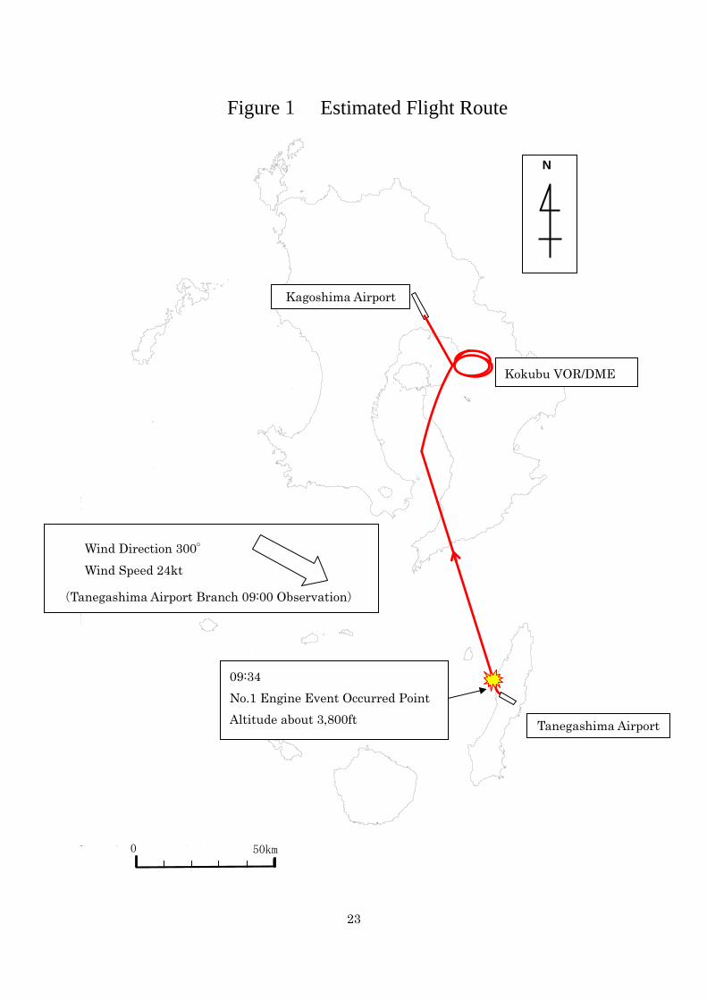
On March 25 (Wednesday), 2009, at 9:33 Japan Standard Time (JST: unless otherwise stated, all times are indicated in JST (UTC+9h)), a Bombardier DHC-8-402, registered JA847C, operated by Japan Air Commuter as regularly scheduled Flight 3760, took off from Tanegashima Airport. At about 9:34, while the aircraft was climbing in airspace approximately six km north-northwest of Tanegashima Airport bound for Kagoshima Airport, an abnormal noise emanated from the No. 1 engine and instrument indications showed the occurrence of engine failure. The engine was then shut down and the aircraft requested emergency landing clearance from the Kagoshima Radar Approach Control Facility. The aircraft landed at Kagoshima Airport at 10:26.
There were 42 persons on board: the Pilot in Command, the First Officer, two cabin attendants and 38 passengers. No one was injured in the serious incident. 1.2 Outline of the Serious Incident Investigation
1.2.1 Investigation Organization
On March 25, 2009, the Japan Transport Safety Board (JTSB) designated an investigator-in-charge and another investigator to investigate this serious incident.
1.2.2 Representative from Foreign Authorities
An accredited representative of Canada, as the State of Design and Manufacture of the aircraft and the engine of the aircraft involved in this serious incident, and an accredited representative of the United Kingdom, as the State of Design and Manufacture of the propellers of the aircraft, participated in the investigation.
1.2.3 Implementation of the Investigation
March 25 and 26, 2009 Interviews, examination of the aircraft, and examination of onboard documents and engine-related documents
March 30 to May 1, 2009 Analysis of the records of the digital flight data recorder and cockpit voice recorder
April 14 to 17, 2009 Engine teardown examination (conducted in cooperation with the Transportation Safety Board of Canada (TSB))
April 20 to May 22, 2009 Analysis of fracture surfaces of the input gear shaft and other areas (conducted in cooperation with the TSB)
May 11 to 15, 2009 Examination of propeller components (conducted in
2
cooperation with the United Kingdom Air Accidents Investigation Branch (AAIB))
June 24 to October 23, 2009 Teardown examination of the feathering pump conducted in the U.S.A. and teardown examination of the feathering pump motor also conducted in the U.S.A. (both in cooperation with the TSB)
December 14, 2009 Analysis of the teardown examination results
1.2.4 Provision of Factual Information to the Civil Aviation Bureau of Japan
The following information obtained from the fact-finding investigation was provided to the Civil Aviation Bureau of the Ministry of Land, Infrastructure, Transport and Tourism, Japan:
(1) In the reduction gear box of the No. 1 engine, the 1st stage input gearshaft and the flange coupling shaft were each fractured at three locations.
(2) The helical input gearshaft was fractured. (The above two items of information were provided on March 31, 2009.) (3) An impurity inclusion was found in the material of the fractured helical input gear
shaft. (This information was provided on June 4, 2009.)
1.2.5 Comments from Parties Relevant to the Cause of the Serious Incident
Comments were invited from parties relevant to the cause of the serious incident.
1.2.6 Comments from the Participating States
Comments were invited from the participating States.
3
2. FACTUAL INFORMATION 2.1 History of the Flight
On March 25, 2009, at 09:33, the Bombardier DHC-8-402, registered JA847C (hereinafter referred to as “the Aircraft”), operated by Japan Air Commuter Co., Ltd. (hereinafter referred to as “the Company”) as the Company’s scheduled Flight 3760, took off from Runway 31 at Tanegashima Airport (hereinafter referred to as “the Airport”).
The flight plan of the Aircraft is outlined below:
Flight rules: Instrument flight rules (IFR) Departure aerodrome: Tanegashima Airport Estimated off-block time: 09:30 Cruising speed: 336 kt Cruising altitude: 12,000 ft Route: KINKO (position reporting point) – KBE
(Kokubu VOR/DME) Destination aerodrome: Kagoshima Airport Total estimated elapsed time: 00 h and 18 min Fuel load expressed in endurance: 2 h and 04 min Persons on board: 44 At the time of the serious incident, the Pilot in Command (hereinafter referred to as “the PIC”)
was sitting in the left seat as the PM (pilot monitoring: pilot mainly in charge of duties other than flying) and the First Officer (hereinafter referred to as “the FO”) was sitting in the right seat as the PF (pilot flying: pilot mainly in charge of flying) in the cockpit of the Aircraft.
According to the communications records between the Aircraft and the Radar Approach Control Facility (hereinafter referred to as “the Approach”) of the Kagoshima Airport Office (hereinafter referred to as “the Airport Office”) and the Fukuoka Area Control Center (hereinafter referred to as “the Fukuoka ACC”), the records of the Digital Flight Data Recorder (hereinafter referred to as “the DFDR”), the records of the Cockpit Voice Recorder (hereinafter referred to as “the CVR”), and the statements from the flight crewmembers, the history of the flight from the time when the Aircraft took off from the Airport to the time when it landed at Kagoshima Airport after this serious incident occurred are as summarized below. 2.1.1 History of the Flight Based on ATC Communications Records and
DFDR/CVR Records
09:33 The Aircraft took off from Runway 31 of the Airport. 09:34:14 The Aircraft contacted the Fukuoka ACC, reporting that it had just passed
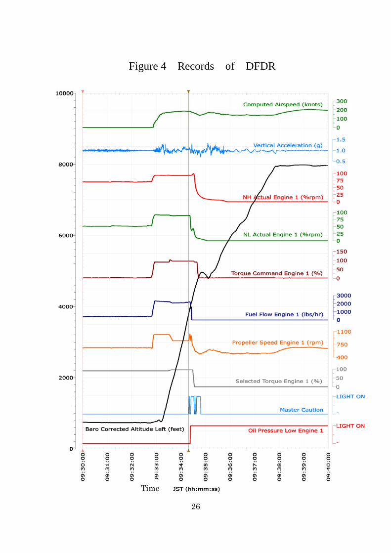
3,700 ft and would continue to climb up to 12,000 ft. 09:34:19 There was a loud bang in the Aircraft. Master caution light came on at approximately 3,800 ft.
4
09:34:23 The oil pressure warning light for the No. 1 engine came on. 09:34:24 NL*1 of the No. 1 engine dropped sharply to approximately 47%. 09:34:26 The Aircraft’s No. 1 engine was shut down. The fuel flow*2 of the No. 1 engine dropped to zero. 09:37:04 The Aircraft contacted the Fukuoka ACC, reporting that it would stop
climbing at 8,000 ft and maintain that altitude. 09:37:15 The Fukuoka ACC provided the Aircraft with clearance for changing the
altitude and maintaining 8,000 ft. 09:42:26 The Aircraft contacted the Fukuoka ACC, requesting permission for an
emergency landing at Kagoshima Airport due to No. 1 engine failure. 09:42:39 The Fukuoka ACC gave the Aircraft permission for an emergency landing at
Kagoshima Airport. 09:45:40 The Aircraft contacted the Approach, asking for wind information at
Kagoshima Airport. 09:45:45 The Approach reported to the Aircraft that at the end of Runway 34 there was
wind from 330° at 22 kt, maximum 31 kt and minimum 17 kt, adding that volcanic smoke had been reported.
09:46:38 The Approach gave the Aircraft permission for a minimum-distance emergency landing.
09:47:45 The Aircraft contacted the Approach, reporting that it would hold for about 10 minutes in the air above Kokubu VOR at an altitude of about 7,000 ft for troubleshooting purposes.
09:59:00 The Aircraft contacted the Approach, reporting that it would climb to 8,000 ft because of cloud.
10:10:30 The Aircraft contacted the Approach, requesting arrangements for fire engines, because, although the No. 1 engine was shut down, it was unable to feather*3 its propeller and thus the Aircraft might experience strong impact upon landing.
10:16:30 The Approach contacted the Aircraft, confirming whether or not the malfunctioning feathering system would necessitate stopping on the runway.
10:16:50 The Aircraft contacted the Approach, reporting that it would be possible for the Aircraft to move clear of the runway because the No. 2 engine was operating.
10:22:20 The Aircraft requested landing clearance from the Kagoshima Airport Tower Control Facility (hereinafter referred to as “the Tower”), and the request was
*1 : “NL” refers to the rotating speed of the low-pressure compressor and low-pressure turbine of the engine. With the
engines of the Aircraft, a speed of 27,000 rpm corresponds to the engine’s full-thrust power and this speed is indicated as 100%.
*2 : “Fuel flow” refers to the fuel flow rate as expressed by the weight of the fuel delivered in a unit of time. *3 : “Feather” means changing the propeller pitch to an angle near 90° in the event of a failure of the corresponding
engine in order to minimize the generation of drag. If the propeller is not feathered, it will continue to windmill, producing drag rather than thrust.
5
granted. 10:26 The Aircraft landed on Runway 34 of Kagoshima Airport. 10:26:40 The Tower announced the closure of the runway for the purpose of
inspection. 2.1.2 History of the Flight Based on the Statements of Flight Crewmembers
(1) PIC The flights on the day of the serious incident were for a shuttle service between
Kagoshima and Tanegashima. During the briefing before the departure from Kagoshima, we received information about favorable weather despite the presence of strong northwesterly winds. After the pre-flight briefing, I went to the apron, where the mechanic in charge explained the maintenance operation results, reporting that nothing abnormal had been found.
Then I conducted an exterior inspection, confirming that there were no problems with the Aircraft.
The pre-flight inspection that we then conducted revealed no problems and there was no sign of abnormality found during the engine start, so we took off as usual from Kagoshima Airport.
It took 25 minutes to fly to the Airport. At the time of landing, there were wind gusts of 20 to 30 kt and the air currents were rather unfavorable.
In preparation for the return flight to Kagoshima, I checked the exterior of the Aircraft as part of the pre-departure inspection and confirmed that the airframe was free of abnormalities.
I sat in the left seat as PM and the FO sat in the right seat as PF; this was for the purpose of giving the FO an opportunity to experience controlling the Aircraft from the right seat. We took off from Runway 31 at the Airport at 9:33. There was nothing abnormal with the Aircraft or anything else during the takeoff.
After takeoff, we retracted the landing gears and, at an altitude of 1,100 ft, raised the flaps while setting the climb power. When the Aircraft climbed beyond 1,800 ft after setting the air speed to 185 kt, we turned on the autopilot.
Just when we were about to begin the after-takeoff checklist following contact with the Fukuoka ACC, we heard a loud bang sounded like an explosion, and the nose of the Aircraft swung slightly to the left. This happened during a turn to the right after taking off from the Airport, at an altitude of about 2,500 ft and at a position three to four nm from Tanegashima VOR/DME.
At the same time as the bang, the amber caution light came on for the No. 1 engine propeller electronic control (PEC) on the overhead panel in the cockpit. Immediately after that, the red oil pressure warning light for the No. 1 engine came on.
I then took over control of the Aircraft from the FO, and promptly shut down the No. 1 engine manually according to the procedure in the manual.
While continuing to climb with the No. 2 engine alone, I found that the amount of rudder
6
trim* 4 was unusually large. Then I realized that the propeller was not feathered. Normally, the propeller is feathered when the corresponding engine is stopped; at that time, however, the propeller was windmilling at a speed of approximately 500 rpm.
While the propeller was thus rotating, I pressed the ALTERNATE FEATHER button in an attempt to feather the propeller, but this did nothing.
Although we were at a point nearer to the Airport than to Kagoshima Airport when the engine failure occurred, I judged it safer for the Aircraft in this condition to land at Kagoshima Airport rather than at the Airport, because the Airport at that time had a strong crosswind and its runway was shorter than the one at Kagoshima Airport.
Instead of the originally planned cruise altitude of 12,000 ft, we requested clearance from the Fukuoka ACC to fly at 8,000 ft, and we headed toward Kagoshima Airport. We used the company radio to contact the Company and report that the propeller could not be feathered and we were going to land at Kagoshima Airport. I asked the cabin attendants about the condition of the passengers and then I explained the situation to the passengers through the PAS, telling them that the Aircraft would land at Kagoshima Airport.
While continuing to fly toward Kagoshima Airport after requesting permission from the Fukuoka ACC for an emergency landing, I made another request to the Fukuoka ACC for clearance to hold above Kokubu because I wanted to feather the propeller before landing. After making the request, I attempted feathering the propeller in different ways while communicating with a ground mechanic through the company radio, but all attempts failed, so I finally decided to land at Kagoshima Airport with the propeller as it was.
Since there was a possible risk of the Aircraft deviating from the runway during the landing at Kagoshima Airport because of the propeller not feathering, even though the runway there is long enough, I explained this to the cabin attendants and told them to instruct the passengers to take the safety position.
After making another PAS announcement to the passengers, I contacted the Approach to request landing clearance and then headed towards Kagoshima Airport.
We were able to successfully land at Kagoshima Airport even though the propeller was not feathered.
(2) FO After landing at the Airport, the PIC instructed me to assume duty as the PF on the flight
for Kagoshima, so I sat in the right seat as the PF. After completing the pre-flight inspection without finding any problems, I started the
engines and initiated takeoff. During the takeoff, I was fully aware of the strong winds blowing at the time. I did not advance the power lever in one go but instead did it in steps, moving the lever to an intermediate position and checking that the torque followed the
*4 : “Trim” here means to operate a small airfoil installed on such control surfaces as the ailerons, elevators and rudder
for the purpose of reducing the force necessary for operating these control surfaces.
7
lever movement before advancing the lever to the final position. I did not notice any abnormal engine sounds at that time.
After taking off from the Airport, we made a right turn at about 1,200 ft and then established communication with the Fukuoka ACC.
Then the PEC caution light for the No. 1 engine came on, a bang was heard at the same time, and the Aircraft swung a little to the left. Immediately after this, the No. 1 engine oil pressure warning light came on.
The Aircraft was then flying at an altitude of about 2,000 ft, at a speed of 185 kt, and in an ordinary climb position.
The Aircraft’s heading at the time I heard the bang was about 345° with the Tanegashima VOR/DME as the reference.
After shutting down the No. 1 engine, it was found that the propeller was not feathering. We contacted the ground through the company radio, reporting that we were going to
land at Kagoshima Airport because of a failure of the No. 1 engine and the illumination of both the PEC caution light and the No. 1 engine oil pressure warning light. We also asked them about any possible methods for feathering the propeller.
Upon receiving the ground mechanic’s advice, telling us that there were no possible methods for dealing with the problem, the PIC decided to make an emergency landing.
The landing at Kagoshima Airport was rather smooth despite the noticeable wind blowing at that time.
This serious incident occurred at about 09:34 in the air about 6 km north-northwest of the Airport (latitude 30°38'02''N, longitude 130°57'10''E).
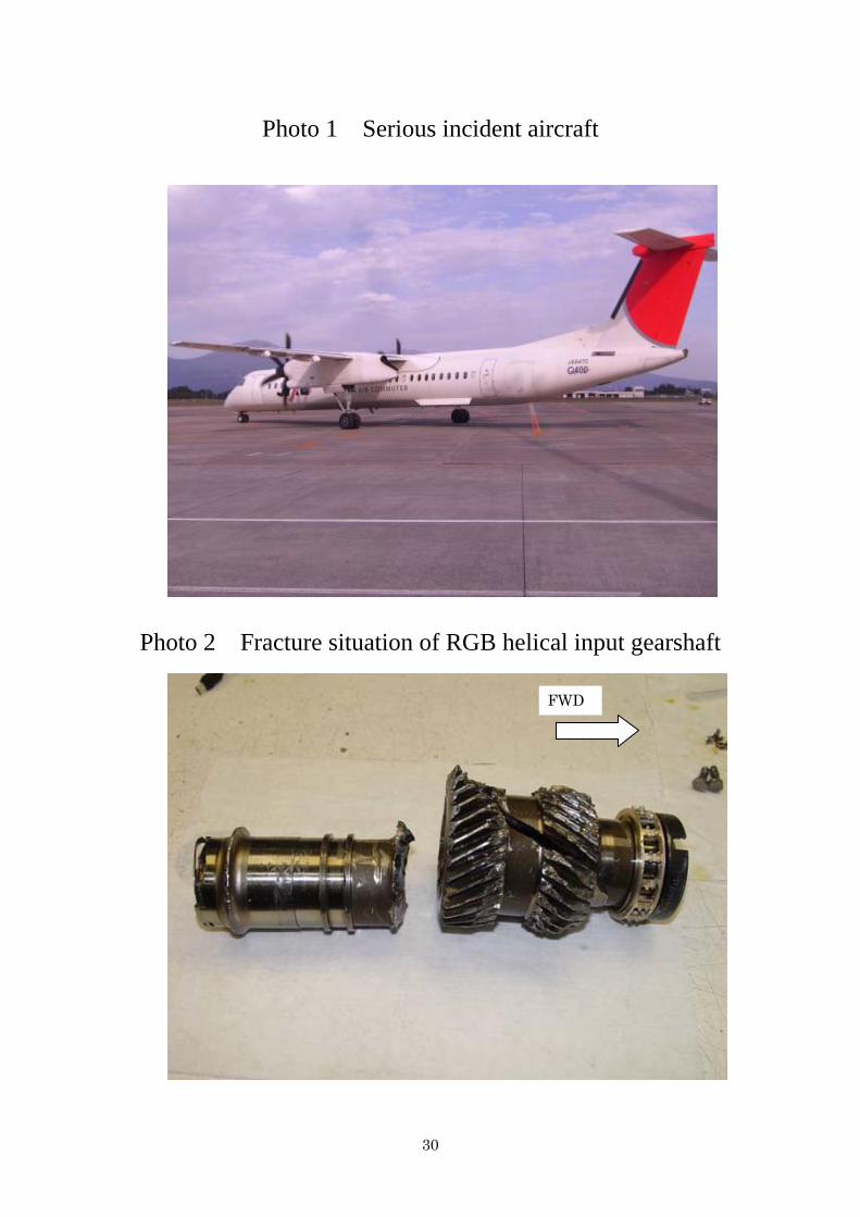
(See Figure 1, Figure 4 and Photo 1) 2.2 Injuries to Persons
No persons were injured. 2.3 Damage to the Aircraft
(1) The No. 1 engine was damaged. (2) The No. 1 feathering pump was damaged. (See Figure 3 and Photos 10 to 16)
2.4 Personnel Information
(1) PIC Male, Age 33 Airline transport pilot certificate (Airplane) April 4, 2008
Type rating for Bombardier DHC-8 February 26, 2004 Class 1 aviation medical certificate
Validity Until April 12, 2009 Total flight time 5,912 h 09 min
Flight time in the last 30 days 62 h 06 min
8
Total flight time on the type of aircraft 2,893 h 35 min Flight time in the last 30 days 62 h 06 min
(2) FO Male, Age 33 Commercial pilot certificate (Airplane) May 1, 2001
Type rating for Bombardier DHC-8 December 20, 2007 Instrument flight certificate December 4, 2002 Class 1 aviation medical certificate
Validity Until March 28, 2009 Total flight time 1,990 h 15 min
Flight time in the last 30 days 53 h 26 min Total flight time on the type of aircraft 618 h 19 min
Flight time in the last 30 days 53 h 26 min
2.5 Aircraft Information
2.5.1 Aircraft
Type Bombardier DHC-8-402 Serial number 4111 Date of manufacture October 15, 2005 Certificate of airworthiness DAI-20-478
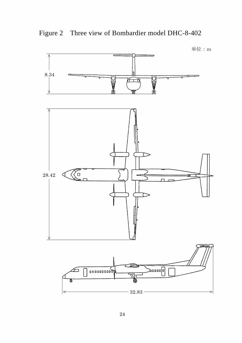
Validity Until November 30, 2009 Total flight time 5,921 h 56 min Flight time since last periodical check (A check on February 1, 2009) 268 h 58 min (See Figure 2)
2.5.2 Engines
(1) No. 1 engine Type Pratt & Whitney Canada PW150A Serial number PCE-FA0170 Date of manufacture September 16, 2002 Total time in service 7,100 h 19 min Total cycles in service 10,167 cycles
(2) No. 2 engine Type Pratt & Whitney Canada PW150A Serial number PCE-FA0198 Date of manufacture November 27, 2003 Total time in service 8,107 h 10 min Total cycles in service 11,411 cycles (See Figure 3)
2.5.3 Fuel and Lubricating Oil
9
The Aircraft used aviation fuel Jet A-1 as the fuel and BP Turbo Oil 2380 as the lubricating oil.
2.5.4 Weight and Balance
When the serious incident occurred, the Aircraft’s weight is estimated to have been 50,375 lb and center of gravity is estimated to have been 24.3% mean aerodynamic chord (MAC), both of which are estimated to have been within the allowable range (maximum takeoff weight of 60,220 lb and 16.7 to 33.2% MAC corresponding to the weight of the Aircraft) at the time of the serious incident. 2.6 Meteorological Information
2.6.1 Aeronautical weather observations for the Airport, located about 6 km south-southeast of the serious incident site, around the time of this serious incident were as follows:
09:00 Wind direction 300°; Wind velocity 24 kt; Visibility 40 km or more Cloud: Amount 1/8, Type Cumulus, Ceiling 3,000 ft Temperature 14°C; Dew point 5°C Altimeter setting (QNH) 29.93 inHg
2.6.2 Aeronautical weather observations for Kagoshima Airport around the time of the emergency landing of the Aircraft were as follows:
10:00 Wind direction 320°; Wind velocity 22 kt; Peak gust 32 kt;
Visibility 30 km or more; Cloud: Amount 1/8, Type Cumulus, Ceiling 2,000 ft,
Amount 5/8, Type Unknown, Ceiling Unknown, Temperature 12°C, Dew point 1°C
Altimeter setting (QNH) 29.94 inHg 2.7 Information on the DFDR and CVR
The Aircraft was equipped with a DFDR (P/N 980-4700-027) and a CVR (P/N 980-6022-011), both manufactured by Honeywell International Inc., U.S.A.
The DFDR and CVR retained the engine data and voice/sound records relevant to the serious incident.
The time was determined by correlating the DFDR-recorded VHF transmission keying signals with the NTT speaking clock recorded on the ATC communication records. 2.8 Details of the Damage to the Aircraft
The condition of the damage to the main parts of the No. 1 engine and No. 1 propeller as found through the teardown examinations was as follows:
10
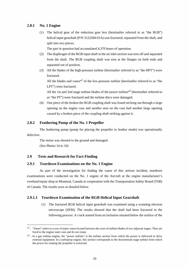
2.8.1 No. 1 Engine
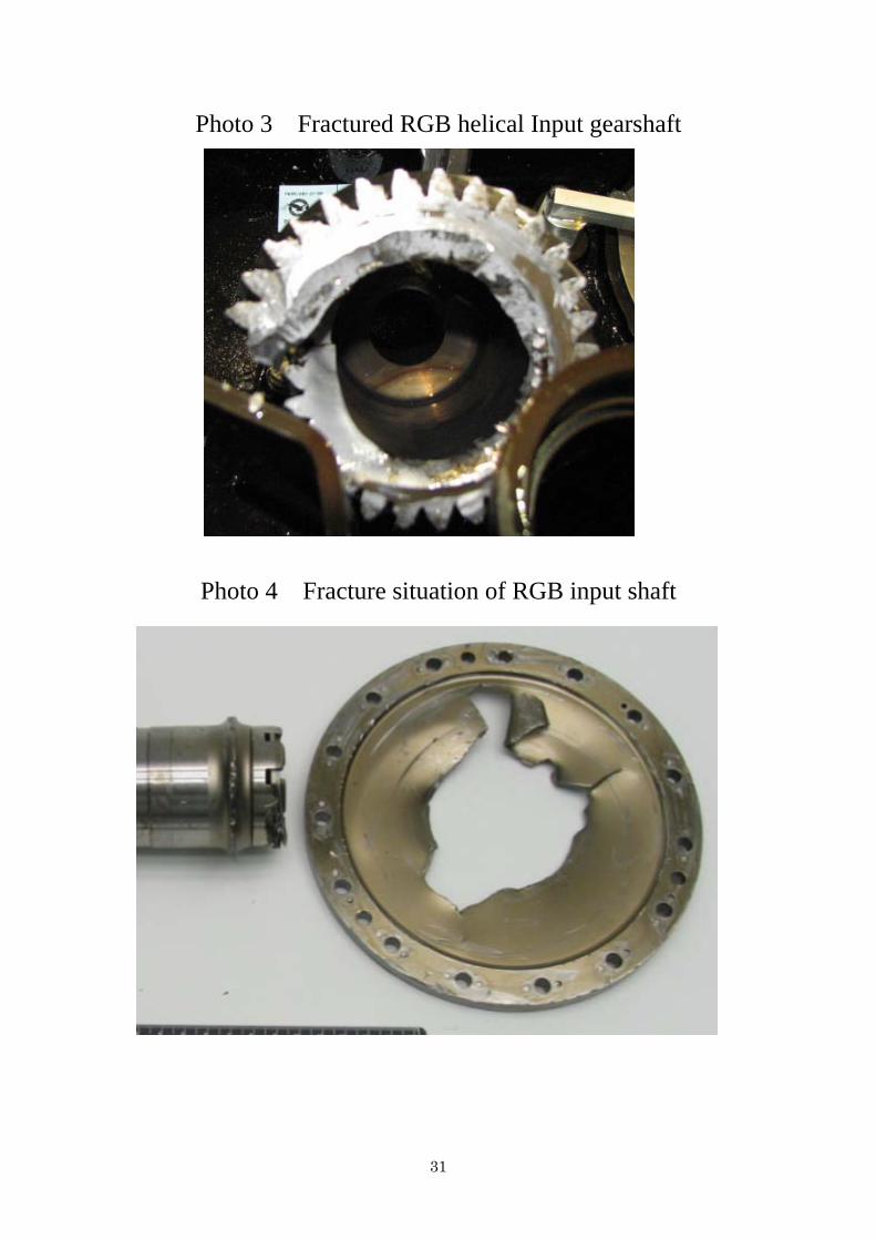
(1) The helical gear of the reduction gear box (hereinafter referred to as “the RGB”) helical input gearshaft (P/N 3122284-01A) was fractured, separated from the shaft, and split into two pieces.
The part in question had accumulated 4,370 hours of operation. (2) The diaphragm of the RGB input shaft in the air inlet section was torn off and separated
from the shaft. The RGB coupling shaft was torn at the flanges on both ends and separated out of position.
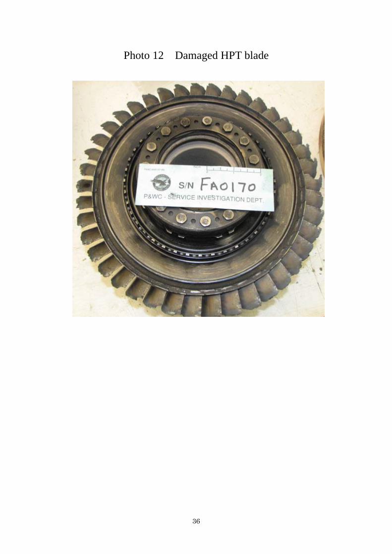
(3) All the blades of the high-pressure turbine (hereinafter referred to as “the HPT”) were fractured.
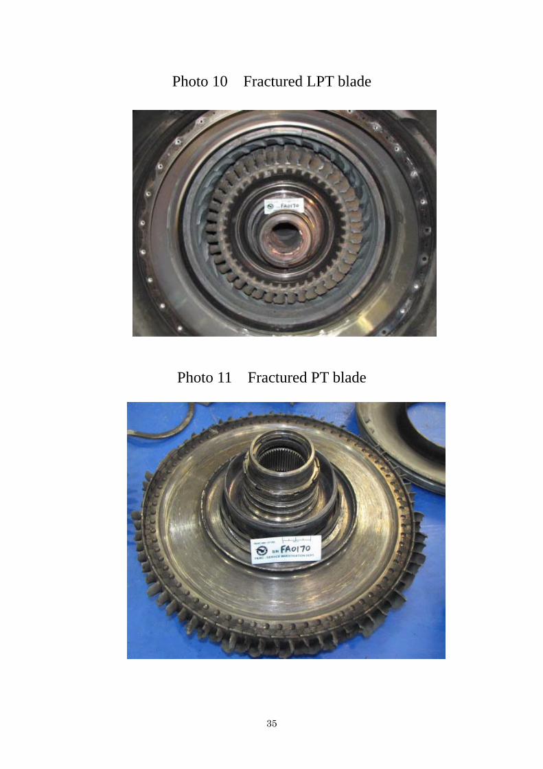
All the blades and vanes*5 of the low-pressure turbine (hereinafter referred to as “the LPT”) were fractured.
All the 1st and 2nd stage turbine blades of the power turbine*6 (hereinafter referred to as “the PT”) were fractured and the turbine discs were damaged.
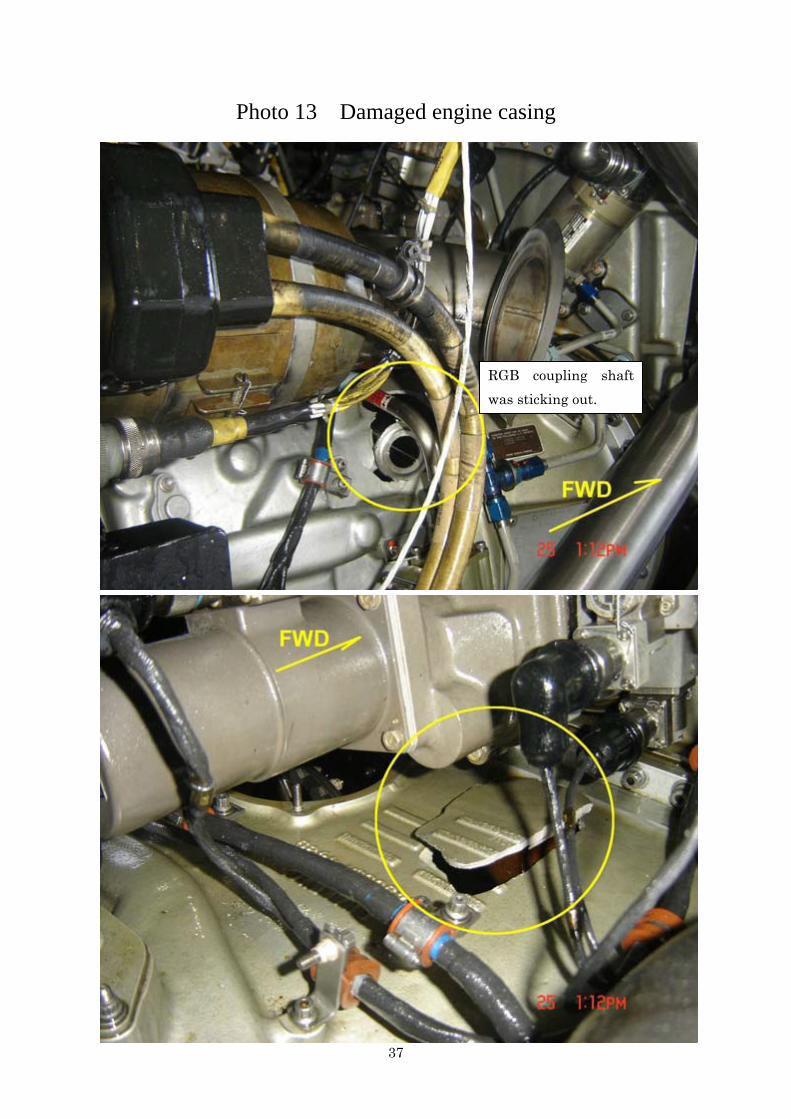
(4) One piece of the broken the RGB coupling shaft was found sticking out through a large opening on the engine case and another area on the case had another large opening caused by a broken piece of the coupling shaft striking against it.
2.8.2 Feathering Pump of the No. 1 Propeller
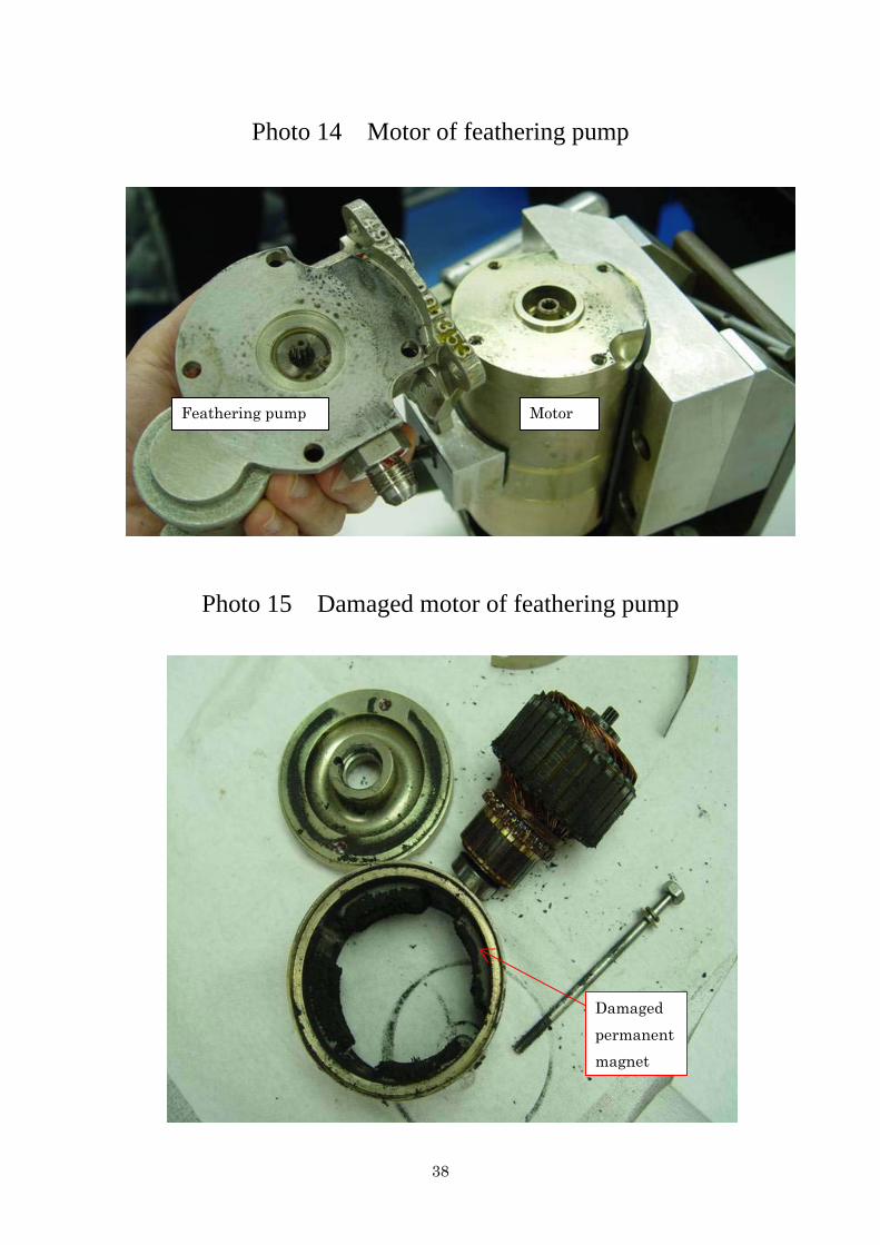
The feathering pump (pump for placing the propeller in feather mode) was operationally defective.
The motor was shorted to the ground and damaged. (See Photos 14 to 16)
2.9 Tests and Research for Fact-Finding
2.9.1 Teardown Examinations on the No. 1 Engine
As part of the investigation for finding the cause of this serious incident, teardown examinations were conducted on the No. 1 engine of the Aircraft at the engine manufacturer’s overhaul/repair shop in Montreal, Canada in cooperation with the Transportation Safety Board (TSB) of Canada. The results were as detailed below. 2.9.1.1 Teardown Examination of the RGB Helical Input Gearshaft
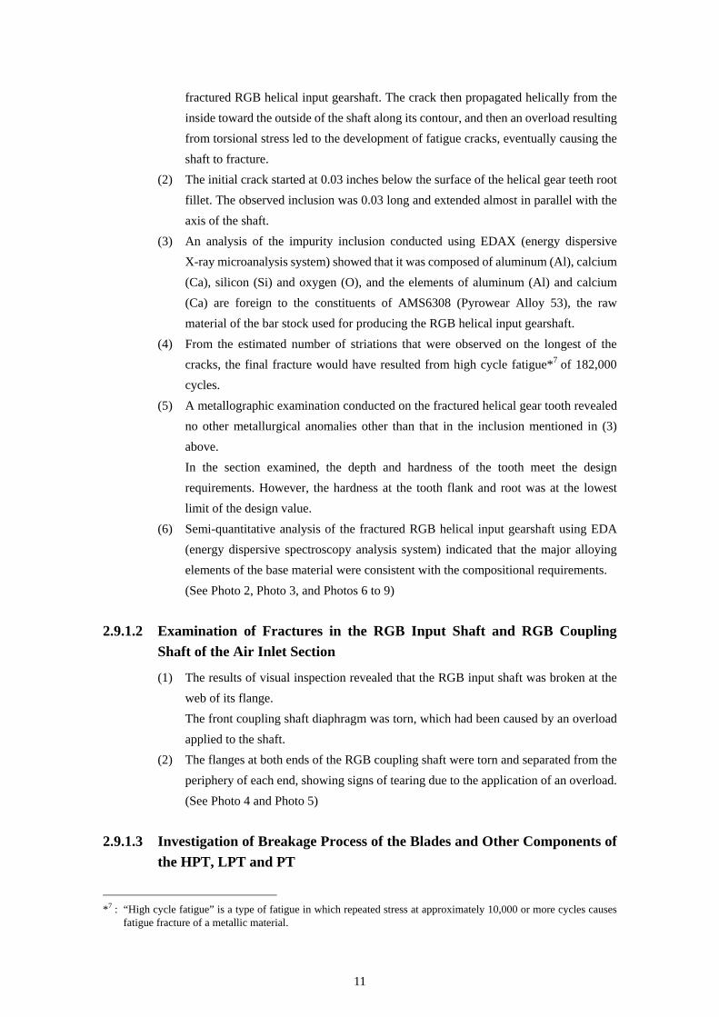
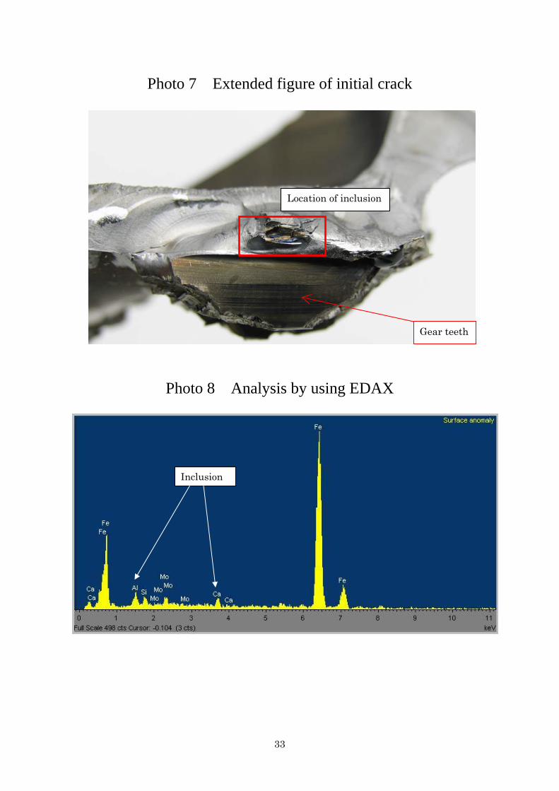
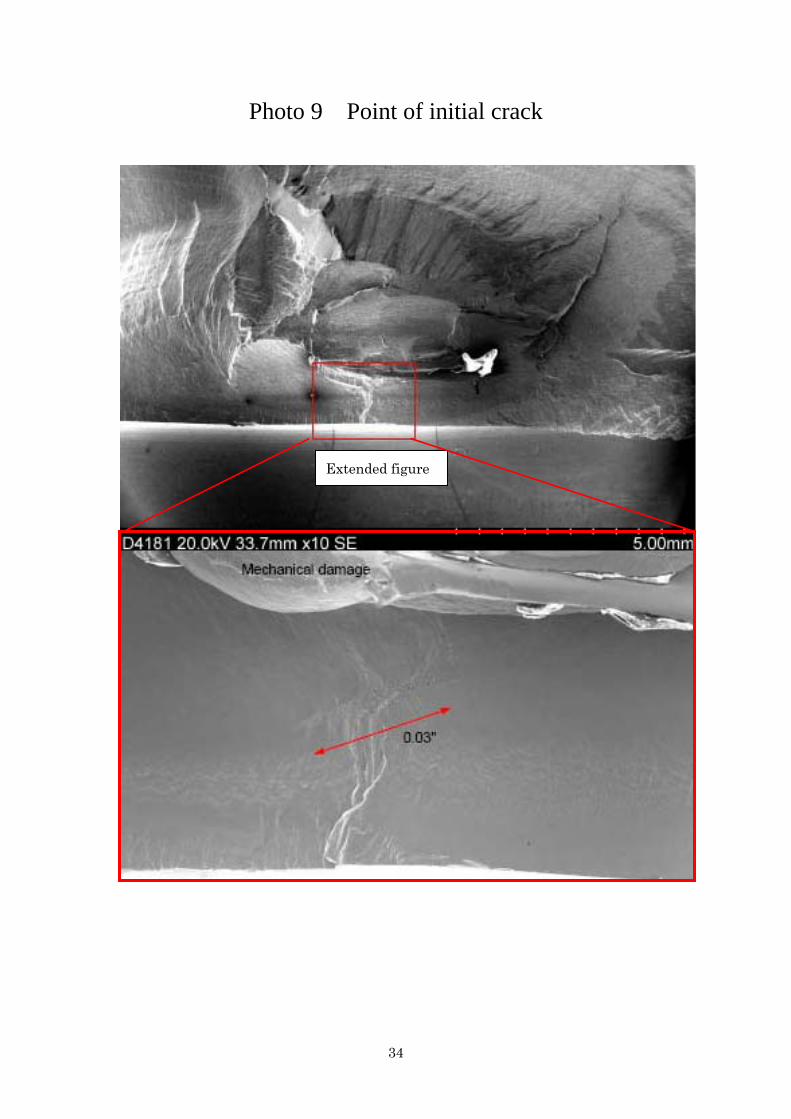
(1) The fractured RGB helical input gearshaft was examined using a scanning electron microscope (SEM). The results showed that the shaft had been fractured in the following process: A crack started from an inclusion situated below the surface of the
*5 : “Vanes” refers to a row of stator vanes located between the rows of turbine blades of two adjacent stages. They are
fixed to the engine outer case and do not rotate. *6 : In a gas turbine engine, the “power turbine” is the turbine section from which the power is delivered to drive
external equipment. In a turboprop engine, this section corresponds to the downstream stage turbine from which the power for rotating the propeller is extracted.
11
fractured RGB helical input gearshaft. The crack then propagated helically from the inside toward the outside of the shaft along its contour, and then an overload resulting from torsional stress led to the development of fatigue cracks, eventually causing the shaft to fracture.
(2) The initial crack started at 0.03 inches below the surface of the helical gear teeth root fillet. The observed inclusion was 0.03 long and extended almost in parallel with the axis of the shaft.
(3) An analysis of the impurity inclusion conducted using EDAX (energy dispersive X-ray microanalysis system) showed that it was composed of aluminum (Al), calcium (Ca), silicon (Si) and oxygen (O), and the elements of aluminum (Al) and calcium (Ca) are foreign to the constituents of AMS6308 (Pyrowear Alloy 53), the raw material of the bar stock used for producing the RGB helical input gearshaft.
(4) From the estimated number of striations that were observed on the longest of the cracks, the final fracture would have resulted from high cycle fatigue*7 of 182,000 cycles.
(5) A metallographic examination conducted on the fractured helical gear tooth revealed no other metallurgical anomalies other than that in the inclusion mentioned in (3) above.
In the section examined, the depth and hardness of the tooth meet the design requirements. However, the hardness at the tooth flank and root was at the lowest limit of the design value.
(6) Semi-quantitative analysis of the fractured RGB helical input gearshaft using EDA (energy dispersive spectroscopy analysis system) indicated that the major alloying elements of the base material were consistent with the compositional requirements.
(See Photo 2, Photo 3, and Photos 6 to 9) 2.9.1.2 Examination of Fractures in the RGB Input Shaft and RGB Coupling
Shaft of the Air Inlet Section
(1) The results of visual inspection revealed that the RGB input shaft was broken at the web of its flange.
The front coupling shaft diaphragm was torn, which had been caused by an overload applied to the shaft.
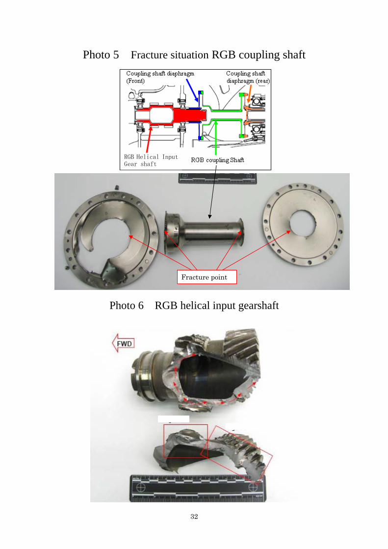
(2) The flanges at both ends of the RGB coupling shaft were torn and separated from the periphery of each end, showing signs of tearing due to the application of an overload.
(See Photo 4 and Photo 5) 2.9.1.3 Investigation of Breakage Process of the Blades and Other Components of
the HPT, LPT and PT
*7 : “High cycle fatigue” is a type of fatigue in which repeated stress at approximately 10,000 or more cycles causes
fatigue fracture of a metallic material.
12
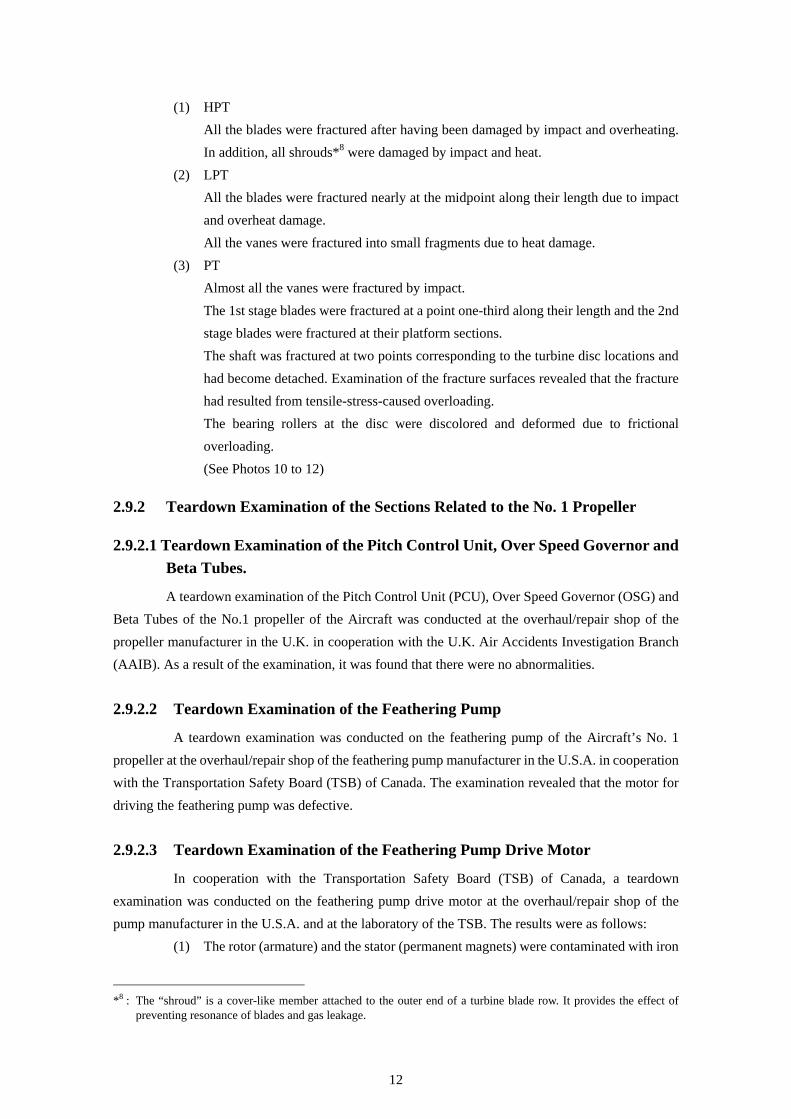
(1) HPT All the blades were fractured after having been damaged by impact and overheating.
In addition, all shrouds*8 were damaged by impact and heat. (2) LPT All the blades were fractured nearly at the midpoint along their length due to impact
and overheat damage. All the vanes were fractured into small fragments due to heat damage. (3) PT Almost all the vanes were fractured by impact. The 1st stage blades were fractured at a point one-third along their length and the 2nd
stage blades were fractured at their platform sections. The shaft was fractured at two points corresponding to the turbine disc locations and
had become detached. Examination of the fracture surfaces revealed that the fracture had resulted from tensile-stress-caused overloading.
The bearing rollers at the disc were discolored and deformed due to frictional overloading.
(See Photos 10 to 12)
2.9.2 Teardown Examination of the Sections Related to the No. 1 Propeller
2.9.2.1 Teardown Examination of the Pitch Control Unit, Over Speed Governor and Beta Tubes.
A teardown examination of the Pitch Control Unit (PCU), Over Speed Governor (OSG) and Beta Tubes of the No.1 propeller of the Aircraft was conducted at the overhaul/repair shop of the propeller manufacturer in the U.K. in cooperation with the U.K. Air Accidents Investigation Branch (AAIB). As a result of the examination, it was found that there were no abnormalities. 2.9.2.2 Teardown Examination of the Feathering Pump
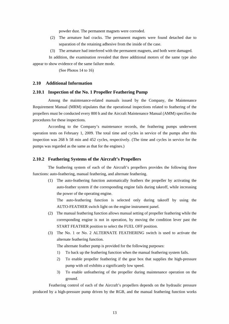
A teardown examination was conducted on the feathering pump of the Aircraft’s No. 1 propeller at the overhaul/repair shop of the feathering pump manufacturer in the U.S.A. in cooperation with the Transportation Safety Board (TSB) of Canada. The examination revealed that the motor for driving the feathering pump was defective. 2.9.2.3 Teardown Examination of the Feathering Pump Drive Motor
In cooperation with the Transportation Safety Board (TSB) of Canada, a teardown examination was conducted on the feathering pump drive motor at the overhaul/repair shop of the pump manufacturer in the U.S.A. and at the laboratory of the TSB. The results were as follows:
(1) The rotor (armature) and the stator (permanent magnets) were contaminated with iron
*8 : The “shroud” is a cover-like member attached to the outer end of a turbine blade row. It provides the effect of
preventing resonance of blades and gas leakage.
13
powder dust. The permanent magnets were corroded. (2) The armature had cracks. The permanent magnets were found detached due to
separation of the retaining adhesive from the inside of the case. (3) The armature had interfered with the permanent magnets, and both were damaged.
In addition, the examination revealed that three additional motors of the same type also appear to show evidence of the same failure mode.
(See Photos 14 to 16) 2.10 Additional Information
2.10.1 Inspection of the No. 1 Propeller Feathering Pump
Among the maintenance-related manuals issued by the Company, the Maintenance Requirement Manual (MRM) stipulates that the operational inspections related to feathering of the propellers must be conducted every 800 h and the Aircraft Maintenance Manual (AMM) specifies the procedures for these inspections.
According to the Company’s maintenance records, the feathering pumps underwent operation tests on February 1, 2009. The total time and cycles in service of the pumps after this inspection was 268 h 58 min and 452 cycles, respectively. (The time and cycles in service for the pumps was regarded as the same as that for the engines.) 2.10.2 Feathering Systems of the Aircraft’s Propellers
The feathering system of each of the Aircraft’s propellers provides the following three functions: auto-feathering, manual feathering, and alternate feathering.
(1) The auto-feathering function automatically feathers the propeller by activating the auto-feather system if the corresponding engine fails during takeoff, while increasing the power of the operating engine.
The auto-feathering function is selected only during takeoff by using the AUTO-FEATHER switch light on the engine instrument panel.
(2) The manual feathering function allows manual setting of propeller feathering while the corresponding engine is not in operation, by moving the condition lever past the START FEATHER position to select the FUEL OFF position.
(3) The No. 1 or No. 2 ALTERNATE FEATHERING switch is used to activate the alternate feathering function.
The alternate feather pump is provided for the following purposes: 1) To back up the feathering function when the manual feathering system fails. 2) To enable propeller feathering if the gear box that supplies the high-pressure
pump with oil exhibits a significantly low speed. 3) To enable unfeathering of the propeller during maintenance operation on the
ground. Feathering control of each of the Aircraft’s propellers depends on the hydraulic pressure produced by a high-pressure pump driven by the RGB, and the manual feathering function works
14
using this hydraulic pressure. If the manual feathering function fails, the alternate feathering pump (electric pump) is then
activated. And if the alternate feathering pump also fails, it is unable to angle the propeller blades to the full feather position, but the propeller blades do rotate under the influence of the counterweights to a lower drag pitch setting. However, effect on aircraft performance and actions to be taken by crew in the event of partially feathered propeller were not described in the Company’s manuals.
In this serious incident, the manual feathering function was also disabled because the fracture of the RGB input shaft blocked the oil passage from the high-pressure pump. 2.10.3 Corrective Actions by Engine Manufacturer
On occurrence of this serious incident, the manufacturer of the Aircraft’s engines, took or planned the following corrective actions:
(1) Removal from service of the remainder of the same material batch of the fractured RGB Input Gearshafts
(2) Inspection of Input Gearshafts on hand at the manufacturer of the Aircraft’s engines and materials on hand at the gearshaft manufacturer
(3) Increased inspection requirements for the bar stock at the material supplier of the Input Gearshaft
(4) Raw material for PW150A Input Gearshafts on hand at the gearshaft manufacturer have been undergone ultrasonic inspection*9 for evidence of subsurface inclusions.
(5) The gearshaft manufacturer has revised AMS 6308 bar stock procurement requirements to add additional ultrasonic inspection at source.
2.10.4 Judgments and Views of the Engine Manufacturer on the RGB Helical
Input Gear Shaft
(1) The viability of requiring ultrasonic inspection of raw material at source for Input Gearshaft production will be reviewed.
(2) The inclusion was found to consist of non-alloy elements (Al, Ca, O, and Si) believed to have been introduced during casting of the AMS 6308 ingots used in the manufacture of the component.
(3) The nozzle through which the molten metal is poured is cleaned and inspected prior to each use and it is replaced/discarded following each pour.
(4) It was confirmed that a maximum of 24 units might have been produced from the same raw material stock used in manufacturing the fractured gearshaft. 21 of these 24 components are currently in service.
(5) AMS 6308 is used in the manufacture of PW150A Second Stage Pinion Gears (2 per RGB).
It has also been in use in the production of PW120 and PW 123 series Input Gearshafts
*9 : “Ultrasonic inspection” is a method of checking for internal flaws in material using high-frequency sound waves
(ultrasonic waves).
15
since 1999. (6) The PW120 and PW123 gearshafts operate at equivalent levels of stress as the
PW150A component. The 490 PW150A engines presently in service have accumulated in excess of 3.0
million hours of operation, while the population of over 1,500 PW120 and PW123 gearshafts in service has accrued an estimated 25 million hours.
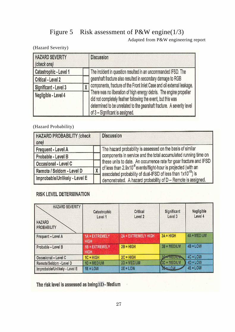
(7) On the basis of this service experience, the occurrence rate for material-related gear fracture is anticipated to be less than 2.9 x 10⁻⁸ events/flight-hour.
(8) The engine manufacturer conducted a risk assessment pertaining to this serious incident.
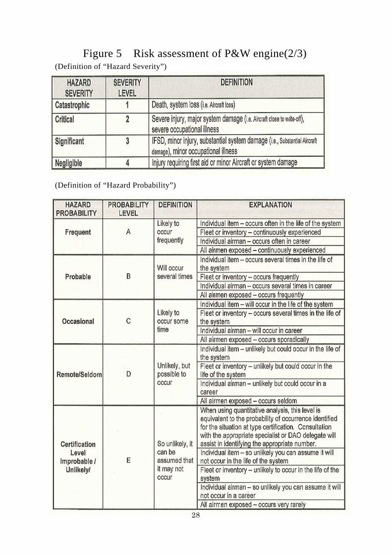
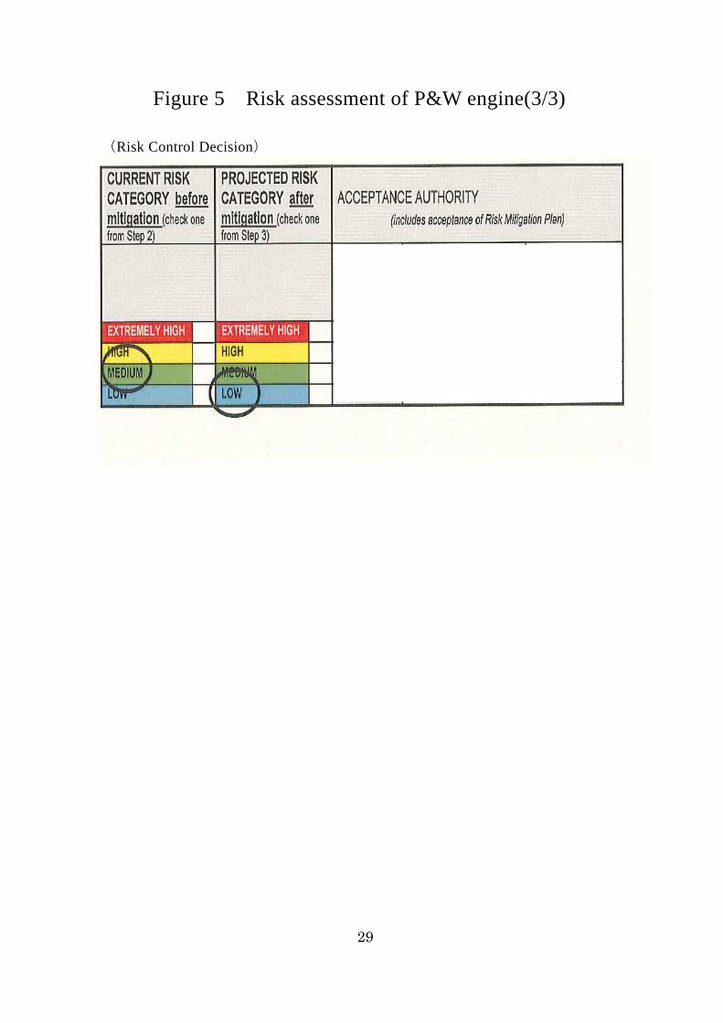
The risk level is determined by the combination of severity and probability of an event. For this serious incident, the severity was rated as “Significant – Level 3” and the probability as “Remote/Seldom – Level D,” and thus the risk level was rated as “3D”; the risk level anticipated after completion of the ultrasonic inspection and other risk-mitigating plan will become “LOW.”
(See Figure 5)
16
3. ANALYSIS 3.1 Crew Qualifications
The PIC and the FO held both a valid airman competence certificate and a valid aviation medical certificate. 3.2 Airworthiness Certificate
The Aircraft had a valid airworthiness certificate and had been maintained and inspected as prescribed. 3.3 Contribution of Meteorological Conditions
It is considered highly unlikely that the meteorological conditions prevailing at the time of this serious incident had any relevance to the occurrence of the incident. 3.4 Time of Occurrence of No. 1 Engine Damage during the Climb after Takeoff
As inferred from the following, it is considered highly probable that the occurrence of the engine damage coincided with the generation of the impact sound from the No. 1 engine at about 3,800 ft during the climb.
(1) As described in 2.1.1, the master caution light of the No. 1 engine came on at 9:34:19 while the Aircraft was climbing at an altitude of approximately 3,800 ft, the oil pressure warning light came on at 9:34:23, and a quick drop of NL to about 47% occurred at 9:34:24.
(2) As described in 2.1.2, the PIC and FO stated that a loud bang sounded like an explosion was heard at about 2,500 ft, and the caution light for the No. 1 engine PEC and then the warning light for the No. 1 engine oil pressure came on. Then the PIC shut down the No. 1 engine.
3.5 Process of Fracture of the No. 1 Engine RGB Helical Input Gearshaft
It is highly probable that, as described in 2.9.1.1 (1), a stress and distortion concentration point had formed on the RGB helical input gearshaft at a subsurface location where an inclusion (0.03 inches long) was present, and this induced the generation of fatigue cracks that then grew helically from the inside toward the outside of the shaft along its contour under torsional stress caused by rotation of the shaft, which eventually resulted in fracture of the shaft.
It is also highly probable that, as described in 2.9.1.1 (2) and (4), the fatigue cracks had started from the impurity inclusion in the helical gear metal stock and subsequent application of repetitive cycles of stress brought about the fracture; the number of repeated stress cycles until the final fracture would be 182,000 as derived from the striations in the longest crack.
17
3.6 Factors Contributing to the Inclusion of Impurities in the No. 1 Engine RGB Helical Input Gearshaft
As described in 2.9.1.1 (3), the RGB helical input gearshaft contained an inclusion composed of aluminum (Al), calcium (Ca), silicon (Si) and oxygen (O), which differed from the constituents of AMS6308, the raw material of the bar stock used for manufacturing the gear shaft.
With regard to the reasons for the inclusion of impurities, it is considered possible that the following causes and the like contributed to this: floats or slag (oxides) that were present as impurities in the steel remained in the raw material, because their complete removal during the refinery process is difficult with the present manufacturing technologies, or impurities that adhered to the mold into which the molten and filtered material was poured caused the inclusion. 3.7 Factors Contributing to the Fracture of the RGB Input Shaft and RGB
Coupling Shaft of the Air Inlet Section
With regard to the fracture of the RGB input shaft and the RGB coupling shaft of the air inlet section, it is considered highly probable that, as described in 2.9.1.2, torsional overload was generated in the RGB helical input gearshaft due to the fatigue fracture of the RGB helical input gearshaft during its high-speed rotation, and as a result, the shaft flanges and the shaft diaphragm of the RGB input shaft and RGB coupling shaft were torn off and these shafts were eventually fractured. 3.8 Process of the Fracture of the HPT, LPT and PT
As described in 2.9.1.3 (1) to (3), it is considered highly probable that all of the HPT, LPT and PT turbine sections were fractured and damaged due to secondary breakage caused by overload on these components as a result of the RGB helical input gearshaft fatigue fracture. 3.9 Process of the Fracture of the No. 1 Engine Case
It is highly probable that, after the fracture of the RGB coupling shaft, a broken piece of the coupling shaft was striking against the engine case, and therefore the broken piece stuck out through a large opening on the engine case and another area on the case had another large opening as described in 2.8.1 (4). 3.10 Factors Contributing to the Failure of the No. 1 Propeller to Feather
As described in 2.1.2 (1) and (2), the PIC and FO stated that a failure had occurred in the No. 1 engine during the climb after takeoff and the No. 1 propeller had failed to feather at the time of the No. 1 engine shutdown.
With regard to the failure of the alternate feather function to work on the No. 1 propeller, it is considered highly probable that, as described in 2.9.2.1, this condition resulted from the failure of the feathering pump drive motor of the No. 1 propeller.
With regard to the motor failure, it is considered highly probable that the corroded permanent magnets having separated from the inside of the motor case interfered with the armature, causing
18
damaging to both. In this serious incident, as described in 2.10.2, the manual feathering function also did not
work, because the oil passage from the high-pressure pump was blocked by the fracture of the RGB input shaft.
Also as described in 2.10.2, if manual feathering and also alternate feathering failed to function, the propeller blades do rotate at partially feathered angle under the influence of the counterweights. However, effect on aircraft performance and actions to be taken by crew in this case were not described in the Company’s manuals. Considering that, this had increased the crew’s workload even though this had not brought serious problems in the serious incident, the effect on aircraft performance in the case of partially feathered angle should be assessed, and then the actions to be taken by crew should be included in relevant manuals if necessary.
In the case of engine breakdown accompanied by an impaired lubricating oil system like this serious incident, the windmilling propeller may cause secondary damage to bearings and other components in the RGB.
For the above reasons, taking into account this serious incident and the fact that three additional motors of the same type also appear to show evidence of the same failure mode as described in 2.9.2.3, the quality of the motor should be assessed, and then it should be improved if necessary. 3.11 Improvement in Quality Control during the Manufacturing Process of the
Engine Component
In this serious incident, it is considered highly probable that the fatigue fracture initiated from the inclusion of impurities that had become mixed in the bar stock during the manufacturing process of the engine component in question at the material supplier’s plant, as described in 3.5 and 3.6.
The fatigue strength of the material is substantially affected by metallographic unevenness. To prevent fatigue fracture, it is imperative to, as far as possible, avoid forming stress or strain
concentration points and to prevent leaving impurities that potentially constitute origin of fatigue fracture in any material metal stock.
With regard to the material quality control in the manufacturing process of the RGB helical input gearshaft, it is necessary for the engine manufacturer to devote continuous company-wide efforts including the management of the metal stock supplier and component manufacturer to improve quality control by keeping track of the details of the quality control (quality assurance) activity of the metal stock supplier and of the component manufacturer for preventing impurity inclusions in raw materials during the manufacture of the component. 3.12 Risk Assessment for this Serious Incident
The engine manufacturer assigned the hazard level of “Significant – Level 3” to this serious incident considering the occurrence of an in-flight shutdown (IFSD).
The actual events experienced in this serious incident, however, included the entire loss of all functions of the propeller feathering due to the defective feathering pump drive motor and blocked oil passage due to the fracture of the RGB helical input gearshaft.

19
Since the propeller feathering function is significantly important to the safety of aircraft operation after the occurrence of an IFSD, the appropriateness of the risk assessment results for this serious incident is questionable, because it is based only on the engine IFSD. The risk assessment should be made in view of the safety of the entire aircraft, not of the engine alone. In addition, this risk assessment should include the assessment of the effect on aircraft performance in the case of partially feathered angle and the assessment of the quality of the feathering pump drive motor.
20
4. PROBABLE CAUSE
It is highly probable that this serious incident occurred through the following series of events: While the Aircraft was climbing after takeoff, the RGB helical input gearshaft of the No. 1 engine sustained fatigue fracture and was detached from its position; the fragments of the broken shaft then flew off, damaging the engine case and breaking the blades of the HPT and the blades and vanes of the LPT and PT at the downstream stages, and this resulted in breakdown of the engine.
With regard to the fatigue fracture of the RGB helical input gearshaft, it is considered probable that fatigue cracks had started from the impurity inclusion present in the metal stock of the helical gear developed in the shaft, and after undergoing repetitive application of stress, the shaft was finally fractured.
21
5. SAFETY RECOMMENDATION
In view of this serious incident, the Japan Transport Safety Board recommends that Transport Canada Civil Aviation (TCCA) give careful consideration to the following and take necessary measures thereof:
(1) Considering the detrimental effect on safety brought about by the inclusion of impurities in the RGB helical input gearshaft of the engine involved in this serious incident, P&WC, the manufacturer of the engine, should make company-wide efforts including the management of the metal stock supplier and component manufacturer serving P&WC, towards improved quality control concerning the production of the RGB helical input gear shaft.
(2) P&WC assigned a hazard severity of “Significant – Level 3” to this serious incident by considering only the occurrence of an IFSD as the basis for the risk level determination, but the actual conditions included the loss of all functions of the feathering system for the propeller of the shutdown engine in addition to the engine in IFSD.
The risk assessment of this serious incident should not be made only on the engine necessitating an IFSD, but instead the incident must be reassessed from the viewpoint of the safety of the entire aircraft, and safety improvement actions should be taken if the results of the reassessment indicate this to be necessary.
22
6. REFERENTIAL MATTERS
To prevent the recurrence of cases similar to this serious incident, the engine manufacturer and the Company took the following actions: 6.1 Actions Taken by the Engine Manufacturer
(1) Issuance of service bulletin In order to improve the overall reliability and durability of its engines, P&WC issued
Service Bulletin PW150-72-35229 dated May 7, 2009, its first revision on May 8, 2009 and second revision on May 12, 2009.
The bulletin and revisions required to replace the RGB input gearshafts potentially affected by impurities with new ones by June 1, 2011 in order to preclude the possible occurrence of similar fractures.
(2) Issuance of Special Inspection (SI) requiring inspection of RGB 1st stage input gearshaft Following the occurrence of the in-flight shutdown event in Japan, P&WC issued an SI
dated March 27, 2009 containing the following instruction for visual inspection of the 1st stage input gearshaft and the RGB flange coupling shaft assembly:
To prevent the recurrence of similar events, all relevant engines should be inspected within a period not exceeding 100 flight hours.
6.2 Actions Taken by the Company
(1) Replacement of RGB input gearshaft Having acquired the relevant information on the engine in question before receiving Service Bulletin (SB) PW150-72-35229, the Company issued an engineering order to conduct a borescope inspection on the RGB input gearshafts of the PW150A engines of its fleet, which was completed on May 3, 2009. When the Company received the SB later on, it issued another engineering order for engine removal and completed it on September 18, 2009. The Company also completed replacing the RGB input gearshafts in question as per the SB.
(2) Upon receipt of the SI dated March 27, 2009, the Company issued an engineering order to inspect the engines in service and this was completed on April 8, 2009.
23
Kagoshima Airport
Kokubu VOR/DME
09:34 No.1 Engine Event Occurred Point Altitude about 3,800ft Tanegashima Airport
N
50km 0
Figure1 Estimated Flight Route
(Tanegashima Airport Branch 09:00 Observation)
Wind Direction 300° Wind Speed 24kt
24
Figure 2 Three view of Bombardier model DHC-8-402
単位:m 32.83
28.42
8.34
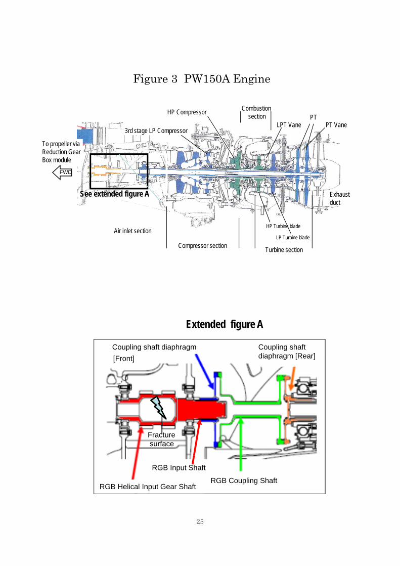
Combustion
Figure 3 PW150A Engine
HP C
FWD
To propeller via Reduction Gear Box module
Combustion section HP Compressor
3rd stage LP Compressor
PT PT Vane LPT Vane
See extended figure A
T bi ti Compressor section
Exhaust duct
HP Turbine blade
LP Turbine blade Air inlet section
Turbine section p
Extended figure A
Coupling shaft diaphragm [Front]
Coupling shaft diaphragm [Rear]
Fracture surface
RGB Helical Input Gear Shaft
RGB Input Shaft
RGB Coupling Shaft
25
26
Time
Figure 4 Records of DFDR
27
Figure 5 Risk assessment of P&W engine(1/3) Adapted from P&W engineering report
(Hazard Severity)
(Hazard Probability)
3D
28
Figure 5 Risk assessment of P&W engine(2/3) (Definition of “Hazard Severity”)
(Definition of “Hazard Probability”)
28
29
Figure 5 Risk assessment of P&W engine(3/3)
(Risk Control Decision)
30
Photo 1 Serious incident aircraft
Photo 2 Fracture situation of RGB helical input gearshaft
FWD
31
Photo 3 Fractured RGB helical Input gearshaft
Photo 4 Fracture situation of RGB input shaft
32
Photo 5 Fracture situation RGB coupling shaft
Photo 6 RGB helical input gearshaft
RGB Helical Input Gear shaft
Fracture point
33
Photo 7 Extended figure of initial crack
Photo 8 Analysis by using EDAX
Location of inclusion
Gear teeth
Inclusion
34
Photo 9 Point of initial crack
Extended figure
35
Photo 10 Fractured LPT blade
Photo 11 Fractured PT blade
36
Photo 12 Damaged HPT blade
37
Photo 13 Damaged engine casing
RGB coupling shaft was sticking out.
38
Photo 14 Motor of feathering pump
Photo 15 Damaged motor of feathering pump
Feathering pump Motor
Damaged permanent magnet
39
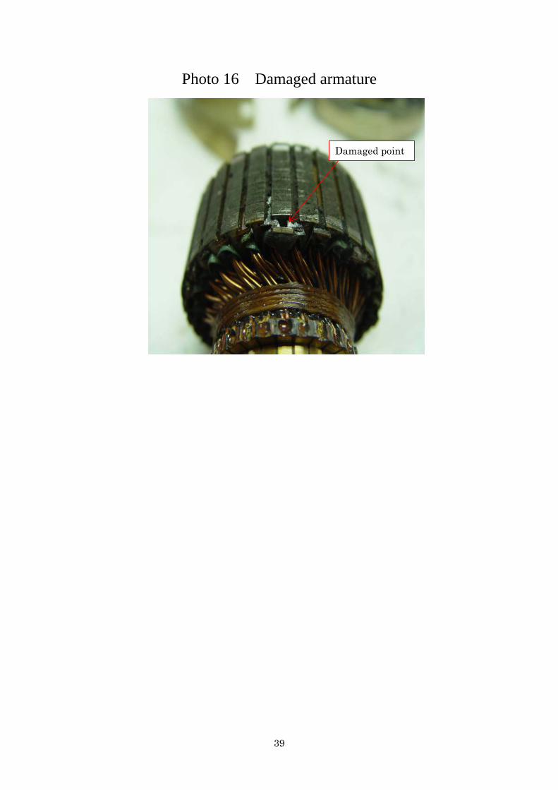
Photo 16 Damaged armature
Damaged point