aircraft operations - dgca.gov.indgca.gov.in/intradgca/intra/icaodocs/doc 8168 - aircraft...
TRANSCRIPT
Doc 8168-OPS/611
Volume II Amendment No. 3
AMENDMENT NO. 3
TO THE
PROCEDURES
FOR
AIR NAVIGATION SERVICES
AIRCRAFT OPERATIONS
VOLUME II
CONSTRUCTION OF VISUAL AND
INSTRUMENT FLIGHT PROCEDURES FIFTH EDITION — 2006
INTERNATIONAL CIVIL AVIATION ORGANIZATION
Checklist of Amendments to the PANS-OPS (Doc 8168), Volume II, Fifth Edition
Date of applicability
Fifth Edition (Approved by the Council on 2 October 2006)
23 November 2006
Amendment No. 1 (Approved by the Council on 30 November 2006)
15 March 2007
Amendment No. 2 (Approved by the President of the Council of ICAO on behalf of the Council on 8 October 2008)
20 November 2008
Amendment No. 3 (Approved by the President of the Council of ICAO on behalf of the Council on 23 July 2010) Replacement pages (iii), (xxv), (xxvi), I-1-1-3, I-1-1-7, I-1-1-8, I-2-1-1 to I-2-1-5, I-2-4-1 to I-2-4-5, II-1-1-2, III-2-6-App A-6, III-3-4-1, III-3-4-2, III-3-4-4, III-5-2-1 to III-5-2-3
18 November 2010

Transmittal note Amendment No. 3 to the Procedures for Air Navigation Services AIRCRAFT OPERATIONS (Doc 8168)
Volume II Construction of Visual and
Instrument Flight Procedures 1. Insert the following new and replacement pages in the PANS-OPS, Volume II (Fifth Edition) to incorporate Amendment No. 3 which becomes applicable on 18 November 2010. a) Page (iii) — Table of Contents b) Pages (xxv) and (xxvi) — Foreword c) Pages I-1-1-3, I-1-1-7 and I-1-1-8 — Part I, Section 1, Chapter 1 d) Pages I-2-1-1 to I-2-1-5 — Part I, Section 2, Chapter 1 e) Pages I-2-4-1 to I-2-4-5 — Part I, Section 2, Chapter 4 f) Page II-1-1-2 — Part II, Section 1, Chapter 1 g) Page III-2-6-App A-6 — Part III, Section 2, Appendix A to Chapter 6 h) Pages III-3-4-1, III-3-4-2 and III-3-4-4 — Part III, Section 3, Chapter 4 i) Pages III-5-2-1 to III-5-2-3 — Part III, Section 5, Chapter 2 2. Record the entry of this amendment on page (ii).

�������
(iii) 23/11/06 15/3/07
No. 1
TABLE OF CONTENTS
Page FOREWORD ...................................................................................................................................... (xv) PART I. GENERAL ............................................................................................................................... I-(i) Section 1. Definitions, abbreviations and acronyms and units of measurement ........................ I-1-(i) Chapter 1. Definitions ................................................................................................................. I-1-1-1 Chapter 2. Abbreviations and acronyms ..................................................................................... I-1-2-1 Chapter 3. Units of measurement................................................................................................ I-1-3-1 Section 2. General principles .......................................................................................................... I-2-(i) Chapter 1. General ...................................................................................................................... I-2-1-1 1.1 Introduction ................................................................................................................... I-2-1-1 1.2 Areas ............................................................................................................................. I-2-1-2 1.3 Obstacle clearance ......................................................................................................... I-2-1-2 1.4 Example calculations .................................................................................................... I-2-1-2 1.5 Bearings, tracks and radials........................................................................................... I-2-1-3 1.6 Navigation system use accuracy ................................................................................... I-2-1-3 1.7 Increased altitudes/heights for mountainous areas ........................................................ I-2-1-3 1.8 Charting accuracy ......................................................................................................... I-2-1-3 1.9 Presentation of significant obstacles and spot elevations on charts .............................. I-2-1-4 1.10 Aircraft characteristics database ................................................................................... I-2-1-4 1.11 Promulgation ................................................................................................................. I-2-1-4 Appendix to Chapter 1. Conversion table for IAS to TAS calculations .............................. I-2-1-App-1 Chapter 2. Terminal area fixes .................................................................................................... I-2-2-1 2.1 General .......................................................................................................................... I-2-2-1 2.2 Terminal area fixes........................................................................................................ I-2-2-1 2.3 Fix tolerance and fix tolerance area for intersecting fixes ............................................ I-2-2-1 2.4 Fix tolerance for other types of navigation instruments ................................................ I-2-2-2 2.5 Fix tolerance overheading a station ............................................................................... I-2-2-3 2.6 Operational application of fixes for flight procedure planning ..................................... I-2-2-4 2.7 Use of fixes for descent and related obstacle clearance ................................................ I-2-2-6 2.8 Protection area for VOR and NDB ............................................................................... I-2-2-7
18/11/10No. 3
(iv) Procedures — Aircraft Operations — Volume II
Page
23/11/06 15/3/07
No. 1
Chapter 3. Turn area construction ............................................................................................... I-2-3-1 3.1 General .......................................................................................................................... I-2-3-1 3.2 Turn inner boundary construction ................................................................................. I-2-3-2 3.3 Turn outer boundary construction ................................................................................. I-2-3-2 Chapter 4. Quality assurance ...................................................................................................... I-2-4-1 4.1 General .......................................................................................................................... I-2-4-1 4.2 The instrument flight procedure process ....................................................................... I-2-4-1 4.3 Procedure design information acquisition ..................................................................... I-2-4-1 4.4 Procedure design ........................................................................................................... I-2-4-2 4.5 Procedure design documentation .................................................................................. I-2-4-2 4.6 Ground and flight validation ......................................................................................... I-2-4-3 4.7 Procedure designer qualifications and training ............................................................. I-2-4-4 4.8 Procedure design automation ........................................................................................ I-2-4-5 Section 3. Departure procedures .................................................................................................... I-3-(i) Chapter 1. Introduction to departure procedures ........................................................................ I-3-1-1 1.1 General .......................................................................................................................... I-3-1-1 1.2 Consultation .................................................................................................................. I-3-1-1 1.3 Standardization ............................................................................................................. I-3-1-1 1.4 Economy ...................................................................................................................... I-3-1-1 1.5 Routes .......................................................................................................................... I-3-1-1 1.6 Related material ............................................................................................................ I-3-1-2 1.7 Abnormal and emergency operations ............................................................................ I-3-1-2 Chapter 2. General concepts for departure procedures ............................................................... I-3-2-1 2.1 Establishment of a departure procedure ........................................................................ I-3-2-1 2.2 Design principles .......................................................................................................... I-3-2-1 2.3 Beginning of the departure procedure ........................................................................... I-3-2-2 2.4 End of the departure procedure ..................................................................................... I-3-2-2 2.5 Minimum obstacle clearance (MOC) ............................................................................ I-3-2-2 2.6 Obstacle identification surface (OIS) ............................................................................ I-3-2-3 2.7 Procedure design gradient (PDG) ................................................................................. I-3-2-3 2.8 Average flight path........................................................................................................ I-3-2-3 2.9 Charting accuracy ......................................................................................................... I-3-2-4 2.10 Additional specific height/distance information ........................................................... I-3-2-4 Chapter 3. Departure routes ........................................................................................................ I-3-3-1 3.1 General .......................................................................................................................... I-3-3-1 3.2 Straight departures ........................................................................................................ I-3-3-1 3.3 Turning departures ........................................................................................................ I-3-3-3 Appendix to Chapter 3. Guidance on environmental issues ............................................... I-3-3-App-1
20/11/08
No. 2
Foreword (xxv)
23/11/06
Amendment Source(s) Subject(s)Approved Applicable
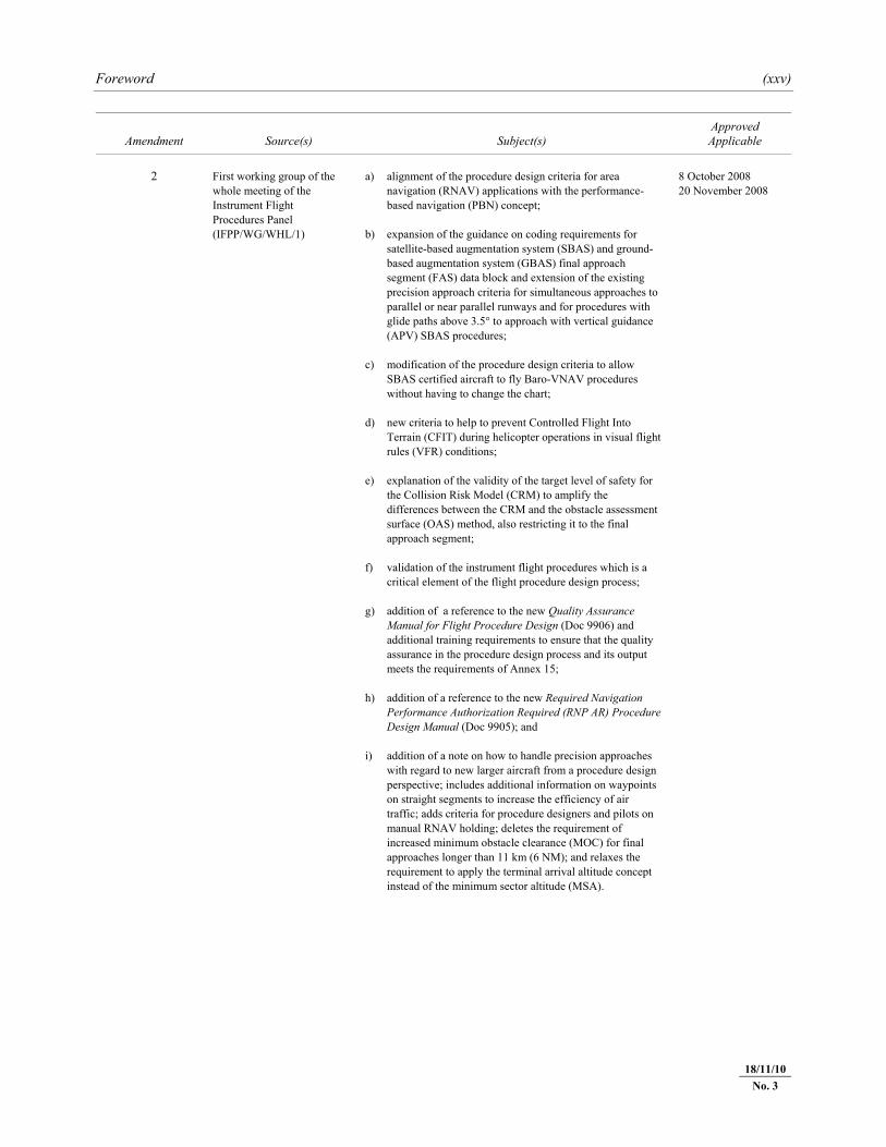
2 First working group of the
whole meeting of the Instrument Flight Procedures Panel (IFPP/WG/WHL/1)
a) alignment of the procedure design criteria for area navigation (RNAV) applications with the performance-based navigation (PBN) concept;
b) expansion of the guidance on coding requirements for
satellite-based augmentation system (SBAS) and ground-based augmentation system (GBAS) final approach segment (FAS) data block and extension of the existing precision approach criteria for simultaneous approaches to parallel or near parallel runways and for procedures with glide paths above 3.5° to approach with vertical guidance (APV) SBAS procedures;
c) modification of the procedure design criteria to allow
SBAS certified aircraft to fly Baro-VNAV procedures without having to change the chart;
d) new criteria to help to prevent Controlled Flight Into
Terrain (CFIT) during helicopter operations in visual flight rules (VFR) conditions;
e) explanation of the validity of the target level of safety for
the Collision Risk Model (CRM) to amplify the differences between the CRM and the obstacle assessment surface (OAS) method, also restricting it to the final approach segment;
f) validation of the instrument flight procedures which is a
critical element of the flight procedure design process; g) addition of a reference to the new Quality Assurance
Manual for Flight Procedure Design (Doc 9906) and additional training requirements to ensure that the quality assurance in the procedure design process and its output meets the requirements of Annex 15;
h) addition of a reference to the new Required Navigation
Performance Authorization Required (RNP AR) Procedure Design Manual (Doc 9905); and
i) addition of a note on how to handle precision approaches
with regard to new larger aircraft from a procedure design perspective; includes additional information on waypoints on straight segments to increase the efficiency of air traffic; adds criteria for procedure designers and pilots on manual RNAV holding; deletes the requirement of increased minimum obstacle clearance (MOC) for final approaches longer than 11 km (6 NM); and relaxes the requirement to apply the terminal arrival altitude concept instead of the minimum sector altitude (MSA).
8 October 2008 20 November 2008
18/11/10No. 3
(xxvi) Procedures — Aircraft Operations — Volume II
23/11/06
Amendment Source(s) Subject(s)Approved Applicable
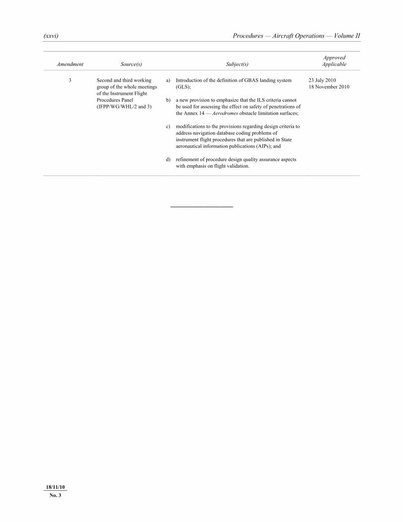
3 Second and third working
group of the whole meetings of the Instrument Flight Procedures Panel (IFPP/WG/WHL/2 and 3)
a) Introduction of the definition of GBAS landing system (GLS);
b) a new provision to emphasize that the ILS criteria cannot
be used for assessing the effect on safety of penetrations of the Annex 14 — Aerodromes obstacle limitation surfaces;
c) modifications to the provisions regarding design criteria to
address navigation database coding problems of instrument flight procedures that are published in State aeronautical information publications (AIPs); and
d) refinement of procedure design quality assurance aspects
with emphasis on flight validation.
23 July 2010 18 November 2010
___________________
18/11/10 No. 3
Part I — Section 1, Chapter 1 I-1-1-3
23/11/06 20/11/08No. 2
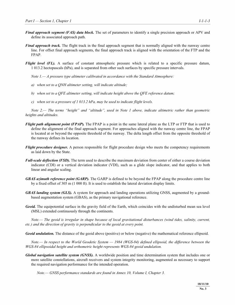
Final approach segment (FAS) data block. The set of parameters to identify a single precision approach or APV and define its associated approach path.
Final approach track. The flight track in the final approach segment that is normally aligned with the runway centre
line. For offset final approach segments, the final approach track is aligned with the orientation of the FTP and the FPAP.
Flight level (FL). A surface of constant atmospheric pressure which is related to a specific pressure datum,
1 013.2 hectopascals (hPa), and is separated from other such surfaces by specific pressure intervals. Note 1.— A pressure type altimeter calibrated in accordance with the Standard Atmosphere: a) when set to a QNH altimeter setting, will indicate altitude; b) when set to a QFE altimeter setting, will indicate height above the QFE reference datum; c) when set to a pressure of 1 013.2 hPa, may be used to indicate flight levels. Note 2.— The terms “height” and “altitude”, used in Note 1 above, indicate altimetric rather than geometric heights and altitudes. Flight path alignment point (FPAP). The FPAP is a point in the same lateral plane as the LTP or FTP that is used to
define the alignment of the final approach segment. For approaches aligned with the runway centre line, the FPAP is located at or beyond the opposite threshold of the runway. The delta length offset from the opposite threshold of the runway defines its location.
Flight procedure designer. A person responsible for flight procedure design who meets the competency requirements
as laid down by the State. Full-scale deflection (FSD). The term used to describe the maximum deviation from center of either a course deviation
indicator (CDI) or a vertical deviation indicator (VDI), such as a glide slope indicator, and that applies to both linear and angular scaling.
GBAS azimuth reference point (GARP). The GARP is defined to be beyond the FPAP along the procedure centre line
by a fixed offset of 305 m (1 000 ft). It is used to establish the lateral deviation display limits. GBAS landing system (GLS). A system for approach and landing operations utilizing GNSS, augmented by a ground-
based augmentation system (GBAS), as the primary navigational reference. Geoid. The equipotential surface in the gravity field of the Earth, which coincides with the undisturbed mean sea level
(MSL) extended continuously through the continents. Note.— The geoid is irregular in shape because of local gravitational disturbances (wind tides, salinity, current, etc.) and the direction of gravity is perpendicular to the geoid at every point. Geoid undulation. The distance of the geoid above (positive) or below (negative) the mathematical reference ellipsoid. Note.— In respect to the World Geodetic System — 1984 (WGS-84) defined ellipsoid, the difference between the WGS-84 ellipsoidal height and orthometric height represents WGS-84 geoid undulation. Global navigation satellite system (GNSS). A worldwide position and time determination system that includes one or
more satellite constellations, aircraft receivers and system integrity monitoring, augmented as necessary to support the required navigation performance for the intended operation.
Note.— GNSS performance standards are found in Annex 10, Volume I, Chapter 3.
18/11/10No. 3
I-1-1-4 Procedures — Aircraft Operations — Volume II
23/11/06 20/11/08 No. 2
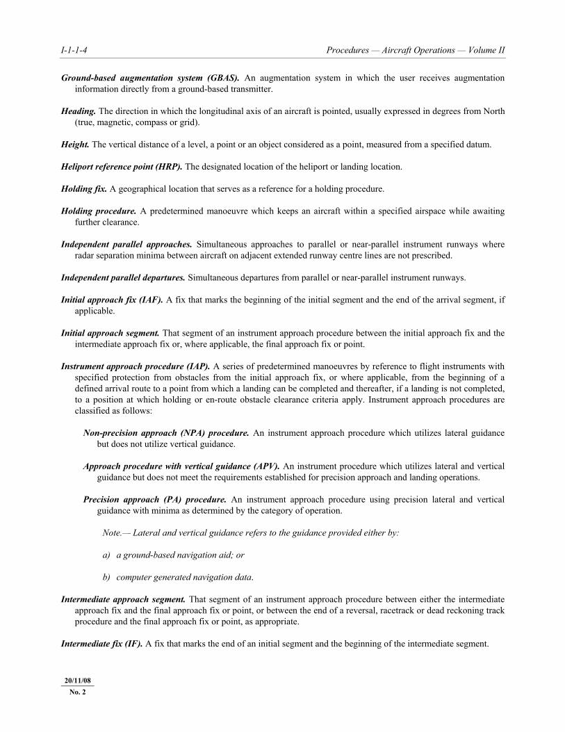
Ground-based augmentation system (GBAS). An augmentation system in which the user receives augmentation information directly from a ground-based transmitter.
Heading. The direction in which the longitudinal axis of an aircraft is pointed, usually expressed in degrees from North
(true, magnetic, compass or grid). Height. The vertical distance of a level, a point or an object considered as a point, measured from a specified datum. Heliport reference point (HRP). The designated location of the heliport or landing location. Holding fix. A geographical location that serves as a reference for a holding procedure. Holding procedure. A predetermined manoeuvre which keeps an aircraft within a specified airspace while awaiting
further clearance. Independent parallel approaches. Simultaneous approaches to parallel or near-parallel instrument runways where
radar separation minima between aircraft on adjacent extended runway centre lines are not prescribed. Independent parallel departures. Simultaneous departures from parallel or near-parallel instrument runways. Initial approach fix (IAF). A fix that marks the beginning of the initial segment and the end of the arrival segment, if
applicable. Initial approach segment. That segment of an instrument approach procedure between the initial approach fix and the
intermediate approach fix or, where applicable, the final approach fix or point. Instrument approach procedure (IAP). A series of predetermined manoeuvres by reference to flight instruments with
specified protection from obstacles from the initial approach fix, or where applicable, from the beginning of a defined arrival route to a point from which a landing can be completed and thereafter, if a landing is not completed, to a position at which holding or en-route obstacle clearance criteria apply. Instrument approach procedures are classified as follows:
Non-precision approach (NPA) procedure. An instrument approach procedure which utilizes lateral guidance
but does not utilize vertical guidance. Approach procedure with vertical guidance (APV). An instrument procedure which utilizes lateral and vertical
guidance but does not meet the requirements established for precision approach and landing operations. Precision approach (PA) procedure. An instrument approach procedure using precision lateral and vertical
guidance with minima as determined by the category of operation. Note.— Lateral and vertical guidance refers to the guidance provided either by:
a) a ground-based navigation aid; or
b) computer generated navigation data. Intermediate approach segment. That segment of an instrument approach procedure between either the intermediate
approach fix and the final approach fix or point, or between the end of a reversal, racetrack or dead reckoning track procedure and the final approach fix or point, as appropriate.
Intermediate fix (IF). A fix that marks the end of an initial segment and the beginning of the intermediate segment.
Part I — Section 1, Chapter 1 I-1-1-7
23/11/06 20/11/08No. 2
Point-in-space (PinS) visual segment. This is the segment of a helicopter PinS approach procedure from the MAPt to the landing location for a PinS “proceed visually” procedure.
Point-in-space reference point (PRP). Reference point for the point-in-space approach as identified by the latitude and
longitude of the MAPt. Primary area. A defined area symmetrically disposed about the nominal flight track in which full obstacle clearance is
provided. (See also Secondary area.) Procedure altitude/height. A specified altitude/height flown operationally at or above the minimum altitude/height and
established to accommodate a stabilized descent at a prescribed descent gradient/angle in the intermediate/final approach segment.
Procedure turn. A manoeuvre in which a turn is made away from a designated track followed by a turn in the opposite
direction to permit the aircraft to intercept and proceed along the reciprocal of the designated track. Note 1.— Procedure turns are designated “left” or “right” according to the direction of the initial turn. Note 2.— Procedure turns may be designated as being made either in level flight or while descending, according to the circumstances of each individual procedure. Racetrack procedure. A procedure designed to enable the aircraft to reduce altitude during the initial approach segment
and/or establish the aircraft inbound when the entry into a reversal procedure is not practical. Reference datum height (RDH). The height of the extended glide path or a nominal vertical path at the runway
threshold. Required navigation performance (RNP). A statement of the navigation performance necessary for operation within a
defined airspace. Note.— Navigation performance and requirements are defined for a particular RNP type and/or application. Reversal procedure. A procedure designed to enable aircraft to reverse direction during the initial approach segment of
an instrument approach procedure. The sequence may include procedure turns or base turns. Satellite-based augmentation system (SBAS). A wide coverage augmentation system in which the user receives
augmentation information from a satellite-based transmitter. Note.— SBAS performance standards are found in Annex 10, Volume I, Chapter 3. Secondary area. A defined area on each side of the primary area located along the nominal flight track in which
decreasing obstacle clearance is provided. (See also Primary area.) Segregated parallel operations. Simultaneous operations on parallel or near-parallel instrument runways in which one
runway is used exclusively for approaches and the other runway is used exclusively for departures. Significant obstacle. Any natural terrain feature or man-made fixed object, permanent or temporary, which has vertical
significance in relation to adjacent and surrounding features and which is considered a potential hazard to the safe passage of aircraft in the type of operation for which the individual procedure is designed.
Note.— The term “significant obstacle” is used in this document solely for the purpose of specifying the objects considered in calculations of relevant elements of the procedure and intended to be presented on an appropriate chart series.
18/11/10
No. 3
I-1-1-8 Procedures — Aircraft Operations — Volume II
23/11/06 20/11/08 No. 2
Standard instrument arrival (STAR). A designated instrument flight rule (IFR) arrival route linking a significant point, normally on an ATS route, with a point from which a published instrument approach procedure can be commenced.
Standard instrument departure (SID). A designated instrument flight rule (IFR) departure route linking the aerodrome
or a specified runway of the aerodrome with a specified significant point, normally on a designated ATS route, at which the en-route phase of a flight commences.
Station declination. The angle between the 360°R of the VOR and true north. Take-off run available (TORA). The length of runway declared available and suitable for the ground run of an
aeroplane taking off. Terminal arrival altitude (TAA). The lowest altitude that will provide a minimum clearance of 300 m (1 000 ft) above
all objects located in an arc of a circle defined by a 46 km (25 NM) radius centred on the initial approach fix (IAF), or where there is no IAF on the intermediate approach fix (IF), delimited by straight lines joining the extremity of the arc to the IF. The combined TAAs associated with an approach procedure shall account for an area of 360 degrees around the IF.
Threshold (THR). The beginning of that portion of the runway usable for landing. Track. The projection on the earth’s surface of the path of an aircraft, the direction of which path at any point is usually
expressed in degrees from North (true, magnetic or grid). Vertical path angle (VPA). Angle of the published final approach descent in Baro-VNAV procedures. Visual manoeuvring (circling) area. The area in which obstacle clearance should be taken into consideration for
aircraft carrying out a circling approach. Visual segment descent angle (VSDA). The angle between the MDA/H at the MAPt/DP and the heliport crossing
height. Waypoint (WD). A specified geographical location used to define an area navigation route or the flight path of an
aircraft employing area navigation. Waypoints are identified as either:
Fly-by waypoint. A waypoint which requires turn anticipation to allow tangential interception of the next segment of a route or procedure, or
Flyover waypoint. A waypoint at which a turn is initiated in order to join the next segment of a route or procedure.
Waypoint distance. Distance on the WGS ellipsoid from a defined waypoint to the aircraft RNAV receiver.
___________________
18/11/10 No. 3
I-2-1-1 23/11/06 18/11/10
No. 3
Chapter 1
GENERAL
1.1 INTRODUCTION 1.1.1 The specifications in this part have been formulated with a view to achieving a reasonable degree of standardization although the improbability of being able to achieve worldwide uniformity of procedure, areas and obstacle clearance for any single type of facility is fully recognized. It is intended therefore that States should take into account their local conditions, in relation to these criteria, when establishing procedures, areas and obstacle clearances. 1.1.2 Only one procedure should be specified for each type of radio aid in relation to a particular runway. Exceptions to this should be permitted only after joint consideration by the State authorities and the operators concerned. The attention of States is particularly drawn, therefore, to the general and basic criteria on which the specifications have been based and the manner in which these criteria should be applied. 1.1.3 Obstacle clearance is the primary safety consideration in developing instrument approach procedures, and because of variable factors such as terrain, aircraft characteristics and pilot ability, the detailed procedures set out in this part are based on present standard equipment and practices. However, the obstacle clearance included in the specifications are considered to be the minimum: they have been evolved taking into consideration the COM and AGA specifications and it is considered that they cannot be reduced with safety. 1.1.4 The advent and burgeoning growth of RNAV procedures has meant that many pilots now habitually fly all instrument flight procedures using guidance based upon the on-board navigation database, regardless of whether the procedures are published as RNAV or conventional procedures. However, not all conventional procedures are capable of being coded into navigation databases. This is particularly the case with departure procedures. In order to mitigate this problem and to ensure improved flyability, procedure designers should: a) keep the design of all procedures as simple as possible; b) develop RNAV procedures instead of conventional procedures wherever possible; c) coordinate closely with the navigation database suppliers whenever introducing a conventional departure
procedure; d) ensure continuity between SIDs and the en-route structure and between the en-route structure, STARs and
approaches with the use of a common fix and compatible altitude at the interface; e) avoid the use of duplicate segments — i.e. a segment declared as part of a STAR and as part of an approach; and f) avoid the use of heading legs intercepting VOR radials with turns of less than 30°. 1.1.5 In the interest of efficiency, regularity and economy, every effort should be made to ensure that equipment is sited and procedures are evolved so as to keep to the minimum consistent with safety, both the time taken in executing an instrument approach and the airspace necessary for the associated manoeuvres.
I-2-1-2 Procedures — Aircraft Operations — Volume II
23/11/06
1.2 AREAS 1.2.1 Each segment has an associated area. Normally the area is symmetrical on both sides of the intended track. In principle, this area is subdivided into primary and secondary areas. However, in some cases, only primary areas are permitted. When secondary areas are permitted, the outer half of each side of the area (normally 25 per cent of the total width) is designated as secondary area. See Figure I-2-1-1. 1.2.2 Calculating secondary area width at a given point. The width of the secondary areas at any point (p) between two fixes may be obtained by linear interpolation from the widths at these fixes according to the equation below (see Figure I-2-1-2):
Wsp = Ws1 + Dp/L (Ws2 – Ws1) where: Ws1 = width of secondary area at first fix Ws2 = width of secondary area at second fix Wsp = width of secondary area at point p Dp = distance of point p from first fix, measured along the nominal track L = distance between the two fixes, measured along the nominal track
1.3 OBSTACLE CLEARANCE Full obstacle clearance is provided throughout the entire area unless secondary areas are identified. In this case full obstacle clearance is provided in the primary area and in the secondary area the obstacle clearance is reduced linearly from the full clearance at the inner edge to zero at the outer edge. See Figure I-2-1-1. The MOC in the secondary areas may be obtained by a linear interpolation from the full MOC at the outer edge of the primary area to zero, according to the equation below (see Figure I-2-1-3):
MOCsy = MOCp*(1 – Y/Ws) where: MOCp = MOC in primary area MOCsy = MOC in secondary area for obstacle at distance Y from outer edge of primary area Ws = Width of secondary area Y = Distance of obstacle from the edge of the primary area, measured perpendicularly to the
nominal track
1.4 EXAMPLE CALCULATIONS All example calculations in this document are based on an altitude of 600 m (2 000 ft) above mean sea level (MSL) and a temperature of ISA + 15°C unless otherwise stated. For speed conversion the factors in the Appendix to Chapter 1 are used.
18/11/10
No. 3
Part I — Section 2, Chapter 1 I-2-1-3
23/11/06 18/11/10
No. 3
1.5 BEARINGS, TRACKS AND RADIALS In planning procedures, degrees true shall be used. However, all published procedures shall be in degrees magnetic in accordance with Annex 4. Radials shall also be expressed in degrees magnetic, and shall further be identified as radials by prefixing the letter “R” to the magnetic bearing from the facility, for example, R-027 or R-310. The published radial shall be that radial which defines the desired flight track. In areas of magnetic unreliability (i.e. in the vicinity of the earth’s magnetic poles) procedures may be established in degrees true.
1.6 NAVIGATION SYSTEM USE ACCURACY 1.6.1 The system accuracies used in the development of obstacle clearance criteria are based on minimum system performance factors. Where it can be shown that one or more of the parameters affecting these values are confidently maintained better than the minimum, smaller accuracy values may be used. The accuracy values result from the root sum square (RSS) of the system tolerances. 1.6.2 When a navigation aid is used to provide track guidance, the tolerance of the intersection fix is based on 2 sigma confidence limits (95 per cent) while the splay of the instrument approach/missed approach procedure areas is based on 3 sigma confidence limits (99.7 per cent). For VOR/NDB tolerances, see Chapter 2, Table I-2-2-1 and Figures I-2-2-9 and I-2-2-11.
1.7 INCREASED ALTITUDES/HEIGHTS FOR MOUNTAINOUS AREAS 1.7.1 When procedures are designed for use in mountainous areas, consideration must be given to induced altimeter error and pilot control problems which result when winds of 37 km/h (20 kt) or more move over such areas. Where these conditions are known to exist, MOC should be increased by as much as 100 per cent. 1.7.2 Procedures specialists and approving authorities should be aware of the hazards involved and make proper addition, based on their experience and judgement, to limit the time in which an aircraft is exposed to lee-side turbulence and other weather phenomena associated with mountainous areas. This may be done by increasing the minimum altitude/height over the intermediate and final approach fixes so as to preclude prolonged flight at a low height above the ground. The operator’s comments should also be solicited to obtain the best local information. Such increases should be included in the State’s Aeronautical Information Publication (AIP), Section GEN 3.3.5, “Minimum flight altitude”. See Annex 15, Appendix 1 (Contents of Aeronautical Information Publication).
1.8 CHARTING ACCURACY 1.8.1 Charting tolerance should be added to the height and location of the controlling terrain feature or obstacle when instrument approach procedures are developed. Vertical tolerance is added to the depicted height or elevation of the object. Horizontal tolerance is added to the perimeter of the controlling terrain feature or obstacle. 1.8.2 When the application of these tolerances creates an unacceptable operational penalty, additional survey information should be used to refine the obstacle location and height data.
I-2-1-4 Procedures — Aircraft Operations — Volume II
23/11/06
1.9 PRESENTATION OF SIGNIFICANT OBSTACLES AND SPOT ELEVATIONS ON CHARTS
To avoid the overloading of charts with information that may potentially obscure important navigation information, careful consideration must be given by the procedures specialists when providing the following information to the cartographers: a) significant obstacles considered in the calculations of the relevant segments of the procedure; and b) appropriate spot elevations required to improve the situational awareness of the underlying terrain. Note.— Specifications for portraying relief and significant obstacles on the Instrument Approach Chart — ICAO are set forth in Annex 4, Chapter 11.
1.10 AIRCRAFT CHARACTERISTICS DATABASE The criteria in PANS-OPS make use of standard conditions for aircraft characteristics. However, allowance is made in the criteria to deviate from these standard conditions when specific airspace requirements apply. The characteristics for specific aircraft can be found on the ICAO website in the aircraft characteristics database (to be developed).
1.11 PROMULGATION 1.11.1 In planning procedures, degrees true shall be used. However, all published procedures shall be in degrees magnetic in accordance with Annex 4. Radials shall also be expressed in degrees magnetic, and shall further be identified as radials by prefixing the letter “R” to the magnetic bearing from the facility, for example, R-027 or R-310. The published radial shall be that radial which defines the desired flight track. In areas of magnetic unreliability (i.e. in the vicinity of the earth’s magnetic poles) procedures may be established in degrees true. 1.11.1.1 Application of magnetic variation a) VOR. Magnetic tracks to or from a VOR are determined by applying the published VOR station declination to
the true VOR radial at the VOR. b) NDB approach, SID, and STAR. Magnetic tracks to or from an NDB on a procedure are determined by taking
the published magnetic variation of the aerodrome and applying it to the true NDB bearing at the NDB. As an exception, when designing STARs and SIDs using long leg distances at latitudes with large variation changes, apply the magnetic variation at the 1/4 and 3/4 points of the total leg distance.
c) NDB en-route. Magnetic tracks from an en-route NDB are determined by taking the published magnetic
variation at the NDB and applying it to the true NDB bearing at the NDB. As an exception, when designing an en-route airway using long leg distances at high latitudes with large variation changes, apply the magnetic variation at the 1/4 and 3/4 points of the total leg distance.
d) ILS, MLS or localizer approach. Magnetic courses for a localizer are determined by taking the published
magnetic variation of the associated aerodrome and applying it to the true localizer course at the localizer. e) NDB en-route defined fix. Magnetic bearings from a fix defined by a bearing to an NDB are determined by
applying the magnetic variation at the fix to the true bearing at the defined fix.
18/11/10
No. 3

Part I — Section 2, Chapter 1 I-2-1-5
23/11/06 18/11/10
No. 3
f) RNAV en-route. For determination of the magnetic track for en-route, apply the published magnetic variation at each waypoint.
g) RNAV terminal procedures. Magnetic variation to be applied to any track used in RNAV procedures, except
RNAV (VOR/DME) procedures, is either the magnetic variation published for the associated aerodrome of departure/intended landing or the station declination of the recommended navaid associated with a particular procedure leg. To determine the magnetic track, apply the published magnetic variation/station declination to the procedure true track. For legs based upon CF, FA or FM path terminators, the aircraft systems use the station declination of the recommended navaid associated with the leg. It is important that suitable navaids are identified as recommended navaids for all such legs. The published magnetic variation of the aerodrome should be used for legs based upon CA, VA and VM path terminators. Magnetic variation for legs based upon other path terminators may be determined using either method. Where a station declination is used, the recommended navaid shall be clearly identified in the procedure description. Magnetic courses for RNAV (VOR/DME) procedures should use the station declination of the referenced VOR/DME for that procedure.
1.11.2 Category H procedures shall not be promulgated on the same instrument approach chart (IAC) as joint helicopter/aeroplane procedures. 1.11.3 Where different values are used they should be promulgated. However, for DME the values in Chapter 2, 2.4.4, “DME” should always be used.
Figure I-2-1-1. Cross-section of straight segment area showing primary and secondary areas
Assumed lowest flight path
MOCMOC
Secondary areaSecondary area
1/4 of1/4 oftotaltotal
Primary area
1/2 oftotal
Total width

I-2-1-6 Procedures — Aircraft Operations — Volume II
23/11/06
Figure I-2-1-2. Width of secondary area
Figure I-2-1-3. Obstacle clearance in secondary areas
— — — — — — — —
FIX2
WSP WP
FIX1
WS1
DPL
WS2
MOCSy
MOCPObstacle
Y
WS
15/3/07
No. 1
I-2-4-1 23/11/06 18/11/10
No. 3
Chapter 4
QUALITY ASSURANCE
4.1 GENERAL 4.1.1 This chapter provides general provisions on quality assurance for the procedure design process. Detailed guidance can be found in the Instrument Flight Procedure Quality Assurance Manual (currently under development). 4.1.2 The State is responsible to ensure that all published instrument flight procedures in their airspace can be flown safely by the relevant aircraft. Safety is not only accomplished by application of the technical criteria in PANS-OPS and associated ICAO provisions, but also requires measures that control the quality of the process used to apply that criteria, which may include regulation, air traffic monitoring, ground validation and flight validation. These measures shall ensure the quality and safety of the procedure design product through review, verification, coordination, and validation at appropriate points in the process, so that corrections can be made at the earliest opportunity in the process. 4.1.3 This chapter seeks to establish the framework for a quality process for procedure design, including inputs, key required elements, recommendations, and expected outputs. 4.1.4 In the interest of safety, and to promote a reasonable degree of standardization, it is desirable, to the greatest degree possible, to implement the provisions in PANS-OPS in a consistent manner, using processes that will minimize the possibility of errors, identify errors that do occur before they impact safety, and provide for continuous improvement of the procedure design process in order to eliminate or reduce future errors. This is especially important in the modern aviation environment, where increasing reliance is placed on computers and the data they process, for navigation and obstacle awareness. 4.1.5 The safety of air navigation is highly dependent on the quality of aeronautical data. Processes for data quality assurance, from data origination through to publication in the States Aeronautical Information Publication (AIP), is detailed in the Instrument Flight Procedure Quality Assurance Manual.
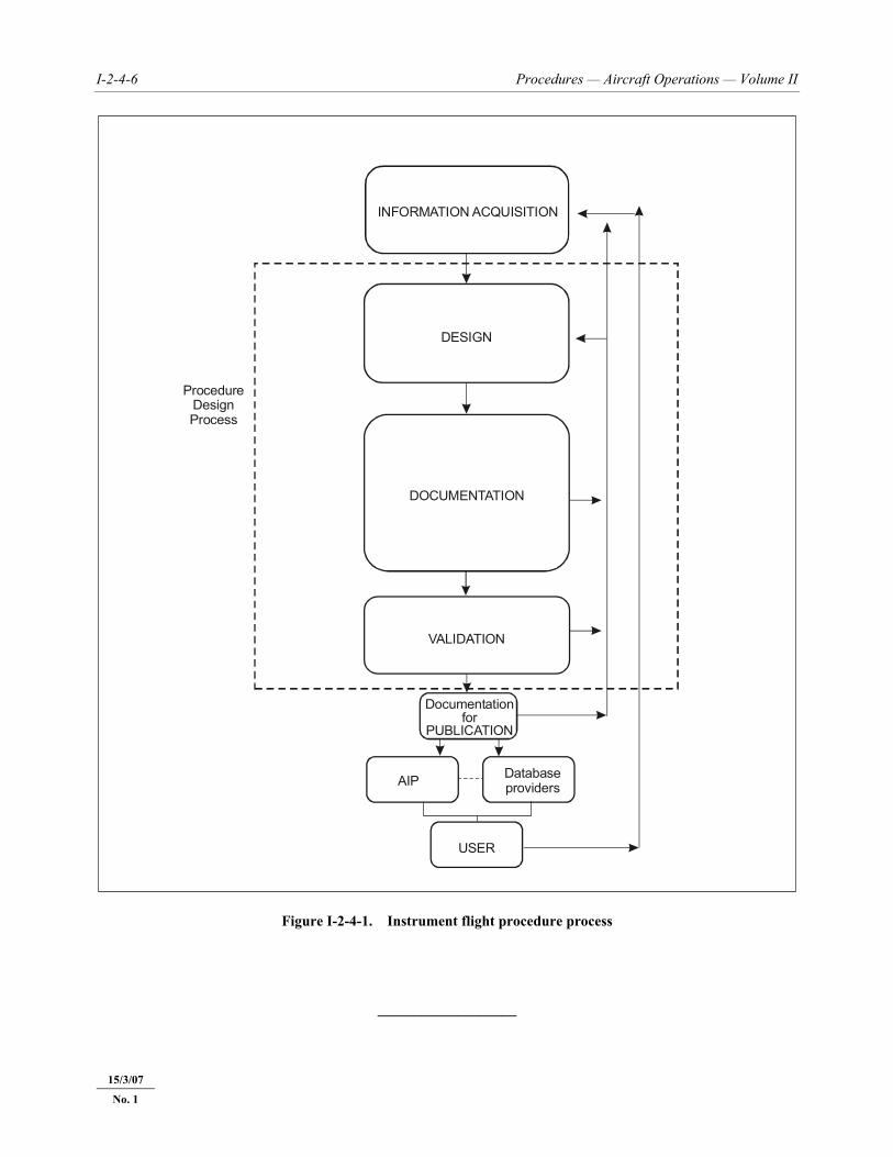
4.2 THE INSTRUMENT FLIGHT PROCEDURE PROCESS The Instrument Flight Procedure (IFP) process (see Figure I-2-4-1) encompasses the acquisition of data, design and promulgation of procedures. It starts with compilation and verification of the many inputs and ends with ground and/or flight validation of the finished product, and documentation for publication. The elements of the process encompass enablers, constraints, output, and post-publication feedback for the procedure under consideration. The IFP process should be followed both for original procedure designs and periodic reviews of existing IFPs.
4.3 PROCEDURE DESIGN INFORMATION ACQUISITION The procedure design information shall be coordinated with all relevant stakeholders. As input for the procedure design process the following aspects need to be assessed:
I-2-4-2 Procedures — Aircraft Operations — Volume II
23/11/06
a) airport, navigation aid, obstacle, and terrain coordinate and elevation data, based on verified surveys and complying with ICAO Annex 11, 14 and 15 requirements;
b) airspace requirements; c) user requirements: needs of Air Traffic Service provider and operators who will use this procedure; d) airport infrastructure such as runway classification, lighting, communications, runway markings, and
availability of local altimeter setting; e) environmental considerations; and f) any other potential issue associated with the procedure.
4.4 PROCEDURE DESIGN 4.4.1 Procedures shall be designed according to State-approved criteria, taking into account all design inputs. Coordination with all concerned parties should continue throughout the procedure design and validation process to ensure that the procedure meets the needs of the user and the community. 4.4.2 Each new or revised procedure shall be verified by a qualified procedure designer other than the one who designed the procedure, to ensure compliance with applicable criteria. 4.4.3 Published procedures shall be subjected to a periodic review, including validation (4.6), to ensure that they continue to comply with changing criteria, to confirm continued adequate obstacle clearance and that they meet user requirements. The individual States shall establish the interval for periodic review of instrument flight procedures according to the needs of the State. The maximum interval for this review is five years.
4.5 PROCEDURE DESIGN DOCUMENTATION 4.5.1 The documentation provided by the procedure designer is divided into three categories and includes: a) documentation required for publication in the States’ AIP in accordance with ICAO Annexes 4 and 15; b) documentation required to maintain transparency concerning the details and assumptions used by the procedure
designer, which should include supporting information/data used in the design, such as: 1) controlling obstacle for each segment of the procedure; 2) effect of environmental considerations on the design of the procedure; 3) infrastructure assessment; 4) airspace constraints; 5) the results of the periodic review and, for modifications or amendments to existing procedures, the reasons
for any changes; 6) for any deviation from existing standards, the reasons for such a deviation and details of the mitigations
applied to assure continued safe operations; and
18/11/10
No. 3
Part I — Section 2, Chapter 4 I-2-4-3
23/11/06 18/11/10
No. 3
7) the results of the final verification for accuracy and completeness (quality assurance checks) prior to validation and then prior to publication;
c) additional documentation required to facilitate ground and flight validation of the procedure and the results of
the ground and flight validation. 4.5.2 All documentation should be retained in accordance with States’ procedures to assist in recreating the procedure in the future in the case of incidents and for periodic review and maintenance. The period of retention shall not be less than the operational lifetime of the procedure.
4.6 GROUND AND FLIGHT VALIDATION
4.6.1 Validation Validation is the necessary final quality assurance step in the procedure design process, prior to publication. The purpose of validation is the verification of all obstacle and navigation data, and assessment of flyability of the procedure. Validation normally consists of ground validation and flight validation. Ground validation shall always be undertaken. When the State can verify, by ground validation, the accuracy and completeness of all obstacle and navigation data considered in the procedure design, and any other factors normally considered in the flight validation (4.6.3), then the flight validation requirement may be dispensed with.
4.6.2 Ground validation
Ground validation is a review of the entire instrument flight procedure package by a person(s) trained in procedure design and with appropriate knowledge of flight validation issues. It is meant to catch errors in criteria and documentation, and evaluate on the ground, to the extent possible, those elements that will be evaluated in a flight validation. Issues identified in the ground validation should be addressed prior to any flight validation. The ground validation will also determine if flight validation is needed for modifications and amendments to previously published procedures.
4.6.3 Flight validation
4.6.3.1 Flight validation of instrument flight procedures should be carried out as part of the initial certification and should also be included as part of the periodic quality assurance programme as established by the individual States to ensure that the procedure design process and its output, including the quality of aeronautical information/data, meet the requirements of Annex 15. It shall be accomplished by a qualified and experienced flight validation pilot, certified or approved by the State. The flight validation pilot shall occupy a seat in the cockpit with a field of view adequate to conduct the flight validation. The objectives of the flight validation of instrument flight procedures are to: a) provide assurance that adequate obstacle clearance has been provided; b) verify that the navigation data to be published, as well as that used in the design of the procedure, is correct; c) verify that all required infrastructure, such as runway markings, lighting, and communications and navigation
sources, are in place and operative; d) conduct an assessment of flyability to determine that the procedure can be safely flown; and
I-2-4-4 Procedures — Aircraft Operations — Volume II
23/11/06
e) evaluate the charting, required infrastructure, visibility and other operational factors. 4.6.3.2 Flight validation should not be confused with flight inspection. Flight inspection of instrument flight procedures is required to assure that the appropriate radio navigation aids adequately support the procedure. This is carried out as part of a formal flight inspection programme and is performed by a qualified flight inspector using an appropriately equipped aircraft. 4.6.4 The procedure designer shall be the originator of all data applicable to conducting a flight validation provided to the flight validation or flight inspection operations activity. The procedure designer should be prepared to provide briefings to the flight validation or flight inspection crews in those cases where flight procedures have unique application or special features. 4.6.5 The procedure designer may participate in the initial validation flight to assist in its evaluation and obtain direct knowledge of issues related to the procedure’s design from the flight inspection or validation pilot and/or inspector.
4.6.6 Flight validation pilot qualifications and training 4.6.6.1 The State shall establish a written policy requiring minimum qualifications, recency of experience, training and competency level standards for flight validation pilots, including those flight inspection pilots who perform flight validation of instrument flight procedures. Flight validation pilot qualifications shall include at least a commercial pilot licence with instrument rating, or an equivalent authorization from the State meeting the Annex 1 knowledge and skill requirements for issue of the commercial pilot licence and instrument rating, in the aircraft category (e.g. aeroplane or helicopter) appropriate for the procedure to be validated. In addition, flight validation pilots shall meet all the experience requirements for the airline transport pilot licence in the relevant category of aircraft (e.g. aeroplane or helicopter) as defined in Annex 1. If the flight validation pilot is not the pilot-in-command of the flight validation aircraft, then the provisions of this paragraph also apply to the pilot-in-command of the flight validation aircraft. Note.— The provisions of Annex 1, 2.6.3.1.2 or 2.6.4.1.2, may be applicable with regard to meeting the experience requirements for the airline transport pilot licence. 4.6.6.2 In order to achieve the safety and quality assurance objectives of the flight validation, each State shall ensure that flight validation pilots have acquired and maintain the required competency level through training and supervised on-the-job training. Note.— Recommended qualifications and training, as well as guidance concerning the skills, knowledge and attitudes to be addressed in the training and evaluation of flight validation pilots can be found in Appendix B of Volume 1 (Flight Procedure Design Quality Assurance System) of the Quality Assurance Manual for Flight Procedure Design (Doc 9906). 4.6.7 Additional detailed information and guidance concerning flight inspection and validation of instrument flight procedures, as well as qualifications and certification of flight inspectors, can be found in the ICAO Manual on Testing of Radio Navigation Aids, Volumes I, II, and III (Doc 8071).
4.7 PROCEDURE DESIGNER QUALIFICATIONS AND TRAINING 4.7.1 Each State shall establish standards for the required competency level for flight procedure design. Each State shall ensure that flight procedure designers have acquired and maintain this competency level through training and supervised on-the-job training (OJT). This is to ensure that the quality assurance in the procedure design process and its output, including the quality of aeronautical information/data, meets the requirements of Annex 15 — Aeronautical Information Services.
18/11/10
No. 3
Part I — Section 2, Chapter 4 I-2-4-5
23/11/06 18/11/10
No. 3
4.7.2 Training for flight procedure design should at least include an initial training and recurrent training at periodic intervals. The State should establish the appropriate interval for recurrent training. 4.7.3 Initial training shall ensure that the flight procedure designer is able to demonstrate a basic level of competency that includes at least the following elements: a) knowledge of information contained in the PANS-OPS, Volumes I and II and other related ICAO provisions
relevant to the State; and b) skills in the design of procedures. 4.7.4 Recurrent training shall ensure that the flight procedure designer is able to demonstrate a basic level of competency that includes at least the following elements: a) knowledge about updates in ICAO provisions and other provisions pertaining to procedure design; and b) maintenance and enhancement of knowledge and skills in the design of procedures. 4.7.5 The State shall ensure that flight procedure designers have undergone an adequate, supervised OJT. 4.7.6 Competency of the flight procedure designer shall be evaluated by the State at regular intervals. 4.7.7 Guidance material for planning, implementing and evaluating flight procedure designer training is provided in the Quality Assurance Manual for Flight Procedure Design, Volume 2 — Flight Procedure Designer Training (Doc 9906).
4.8 PROCEDURE DESIGN AUTOMATION 4.8.1 Procedure design automation tools have the potential to greatly reduce errors in the procedure design process, as well as to standardize the application of the PANS-OPS criteria. For this reason States should use the available software packages to design their instrument flight procedures. 4.8.2 ICAO produces several tools automating elementary portions of the procedure design criteria, where the consequences of error are particularly significant to safety. Included in these tools are the PANS-OPS OAS Software and the PANS-OPS Software (CD-101), providing a means to evaluate the total risk of impact with an obstacle or the ground on precision approaches. 4.8.3 There are numerous other software packages available that automate, to varying degrees, the application of PANS-OPS criteria to the procedure design. The advantages are many, including maintaining the integrity of the source data throughout the design phase, reducing human errors, gaining the capability to develop “what-if” scenarios, and standardized application of the criteria. While software developers test their software extensively, there is no absolute guarantee as to the accuracy of any individual application of the criteria. 4.8.4 As States are responsible for the safety of instrument flight procedures, they should ensure that the software packages used in the design of procedures have been validated. The Procedure Design Software Validation Manual (to be developed), provides guidance to assist States in this task.
I-2-4-6 Procedures — Aircraft Operations — Volume II
23/11/06
Figure I-2-4-1. Instrument flight procedure process
___________________
INFORMATION ACQUISITION
DESIGN
DOCUMENTATION
VALIDATION
Documentationfor
PUBLICATION
AIP
USER
Databaseproviders
ProcedureDesignProcess
15/3/07
No. 1
II-1-1-1 23/11/06
Chapter 1
INSTRUMENT LANDING SYSTEM (ILS)
1.1 INTRODUCTION
1.1.1 Application The ILS criteria detailed in this chapter are related to the ground and airborne equipment performance and integrity required to meet the Category I, II and III operational objectives described in Annex 10.
1.1.2 Procedure construction The procedure from en route to the precision segment of the approach and in the final missed approach phase conforms with the general criteria as presented in Part I, Section 1, 2 and 4. The differences are found in the physical requirements for the precision segment which contains the final approach segment as well as the initial and intermediate phases of the missed approach segment. These requirements are related to the performance of Cat I, II and III systems.
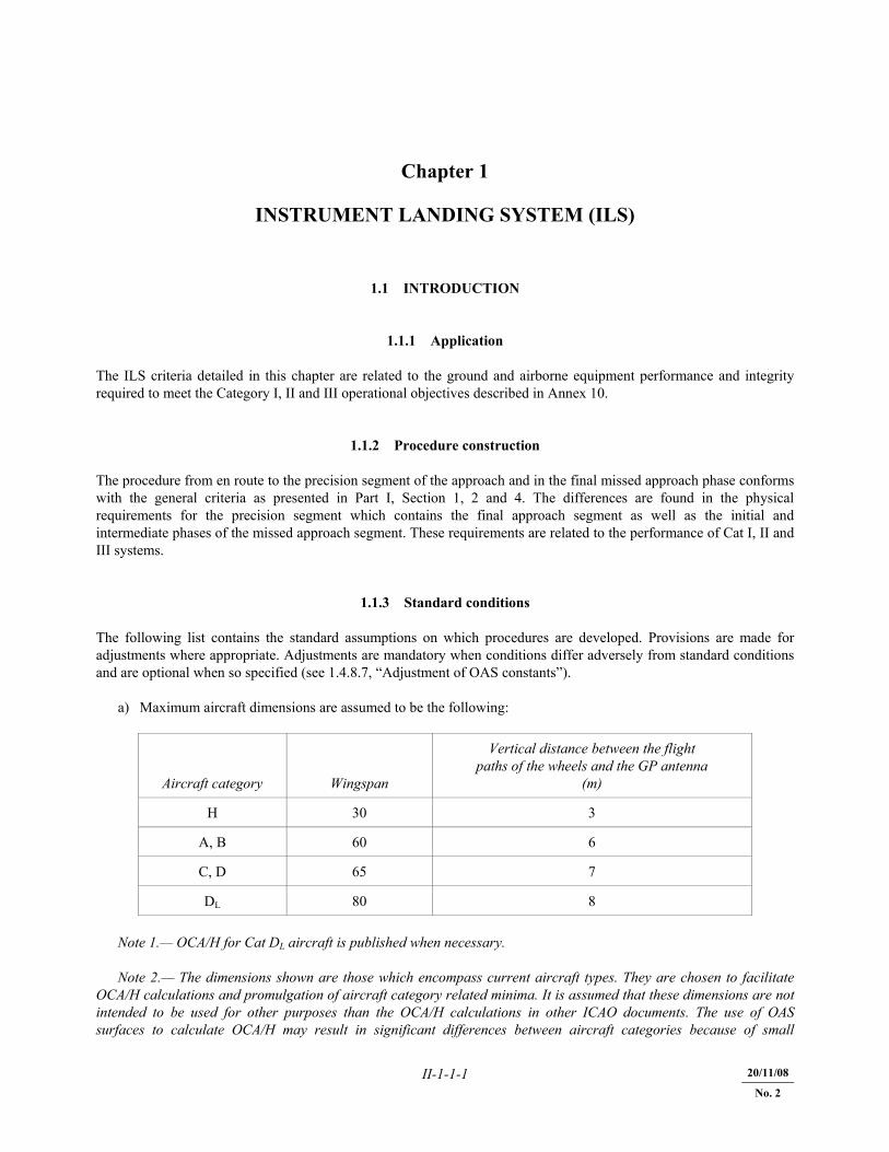
1.1.3 Standard conditions The following list contains the standard assumptions on which procedures are developed. Provisions are made for adjustments where appropriate. Adjustments are mandatory when conditions differ adversely from standard conditions and are optional when so specified (see 1.4.8.7, “Adjustment of OAS constants”). a) Maximum aircraft dimensions are assumed to be the following:
Aircraft category Wingspan
Vertical distance between the flight paths of the wheels and the GP antenna
(m)
H 30 3
A, B 60 6
C, D 65 7
DL 80 8 Note 1.— OCA/H for Cat DL aircraft is published when necessary. Note 2.— The dimensions shown are those which encompass current aircraft types. They are chosen to facilitate OCA/H calculations and promulgation of aircraft category related minima. It is assumed that these dimensions are not intended to be used for other purposes than the OCA/H calculations in other ICAO documents. The use of OAS surfaces to calculate OCA/H may result in significant differences between aircraft categories because of small
20/11/08
No. 2
II-1-1-2 Procedures — Aircraft Operations — Volume II
23/11/06
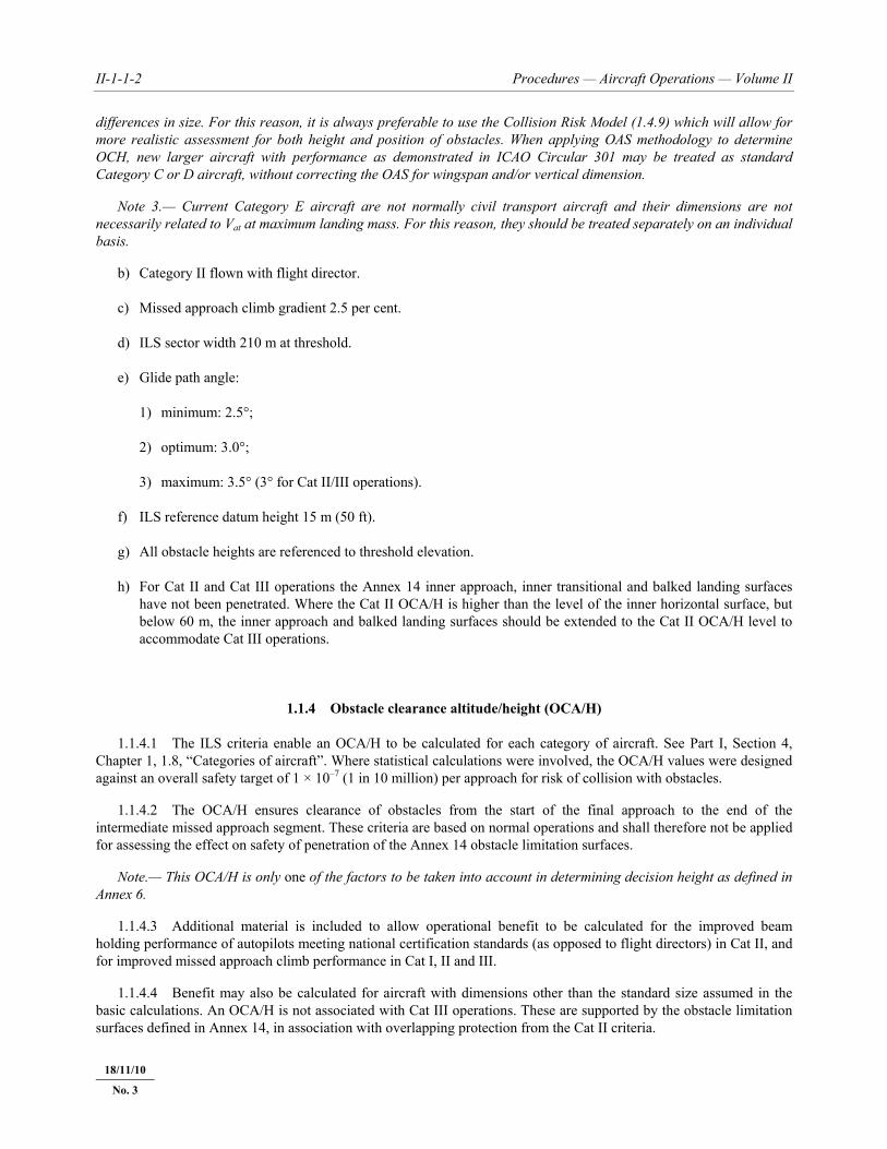
differences in size. For this reason, it is always preferable to use the Collision Risk Model (1.4.9) which will allow for more realistic assessment for both height and position of obstacles. When applying OAS methodology to determine OCH, new larger aircraft with performance as demonstrated in ICAO Circular 301 may be treated as standard Category C or D aircraft, without correcting the OAS for wingspan and/or vertical dimension. Note 3.— Current Category E aircraft are not normally civil transport aircraft and their dimensions are not necessarily related to Vat at maximum landing mass. For this reason, they should be treated separately on an individual basis. b) Category II flown with flight director. c) Missed approach climb gradient 2.5 per cent. d) ILS sector width 210 m at threshold. e) Glide path angle: 1) minimum: 2.5°; 2) optimum: 3.0°; 3) maximum: 3.5° (3° for Cat II/III operations). f) ILS reference datum height 15 m (50 ft). g) All obstacle heights are referenced to threshold elevation. h) For Cat II and Cat III operations the Annex 14 inner approach, inner transitional and balked landing surfaces
have not been penetrated. Where the Cat II OCA/H is higher than the level of the inner horizontal surface, but below 60 m, the inner approach and balked landing surfaces should be extended to the Cat II OCA/H level to accommodate Cat III operations.
1.1.4 Obstacle clearance altitude/height (OCA/H) 1.1.4.1 The ILS criteria enable an OCA/H to be calculated for each category of aircraft. See Part I, Section 4, Chapter 1, 1.8, “Categories of aircraft”. Where statistical calculations were involved, the OCA/H values were designed against an overall safety target of 1 × 10⁻⁷ (1 in 10 million) per approach for risk of collision with obstacles. 1.1.4.2 The OCA/H ensures clearance of obstacles from the start of the final approach to the end of the intermediate missed approach segment. These criteria are based on normal operations and shall therefore not be applied for assessing the effect on safety of penetration of the Annex 14 obstacle limitation surfaces. Note.— This OCA/H is only one of the factors to be taken into account in determining decision height as defined in Annex 6. 1.1.4.3 Additional material is included to allow operational benefit to be calculated for the improved beam holding performance of autopilots meeting national certification standards (as opposed to flight directors) in Cat II, and for improved missed approach climb performance in Cat I, II and III. 1.1.4.4 Benefit may also be calculated for aircraft with dimensions other than the standard size assumed in the basic calculations. An OCA/H is not associated with Cat III operations. These are supported by the obstacle limitation surfaces defined in Annex 14, in association with overlapping protection from the Cat II criteria.
18/11/10
No. 3
Part III — Section 2, Chapter 6 III-2-6-App A-5
23/11/06 20/11/08
No. 2
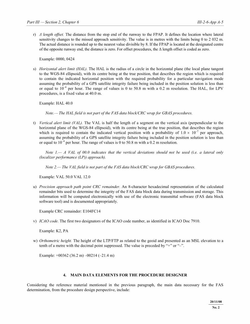
r) Δ length offset. The distance from the stop end of the runway to the FPAP. It defines the location where lateral sensitivity changes to the missed approach sensitivity. The value is in metres with the limits being 0 to 2 032 m. The actual distance is rounded up to the nearest value divisible by 8. If the FPAP is located at the designated centre of the opposite runway end, the distance is zero. For offset procedures, the Δ length offset is coded as zero.
Example: 0000, 0424 s) Horizontal alert limit (HAL). The HAL is the radius of a circle in the horizontal plane (the local plane tangent
to the WGS-84 ellipsoid), with its centre being at the true position, that describes the region which is required to contain the indicated horizontal position with the required probability for a particular navigation mode assuming the probability of a GPS satellite integrity failure being included in the position solution is less than or equal to 10–4 per hour. The range of values is 0 to 50.8 m with a 0.2 m resolution. The HAL, for LPV procedures, is a fixed value at 40.0 m.
Example: HAL 40.0 Note.— The HAL field is not part of the FAS data block/CRC wrap for GBAS procedures. t) Vertical alert limit (VAL). The VAL is half the length of a segment on the vertical axis (perpendicular to the
horizontal plane of the WGS-84 ellipsoid), with its centre being at the true position, that describes the region which is required to contain the indicated vertical position with a probability of 1.0 × 10⁻⁷ per approach, assuming the probability of a GPS satellite integrity failure being included in the position solution is less than or equal to 10–4 per hour. The range of values is 0 to 50.8 m with a 0.2 m resolution.
Note 1.— A VAL of 00.0 indicates that the vertical deviations should not be used (i.e. a lateral only
(localizer performance (LP)) approach). Note 2.— The VAL field is not part of the FAS data block/CRC wrap for GBAS procedures. Example: VAL 50.0 VAL 12.0 u) Precision approach path point CRC remainder. An 8-character hexadecimal representation of the calculated
remainder bits used to determine the integrity of the FAS data block data during transmission and storage. This information will be computed electronically with use of the electronic transmittal software (FAS data block software tool) and is documented appropriately.
Example CRC remainder: E104FC14 v) ICAO code. The first two designators of the ICAO code number, as identified in ICAO Doc 7910. Example: K2, PA w) Orthometric height. The height of the LTP/FTP as related to the geoid and presented as an MSL elevation to a
tenth of a metre with the decimal point suppressed. The value is preceded by “+” or “–”. Example: +00362 (36.2 m) –00214 (–21.4 m)
4. MAIN DATA ELEMENTS FOR THE PROCEDURE DESIGNER Considering the reference material mentioned in the previous paragraph, the main data necessary for the FAS determination, from the procedure design perspective, include:
III-2-6-App A-6 Procedures — Aircraft Operations — Volume II
23/11/06 20/11/08
No. 2
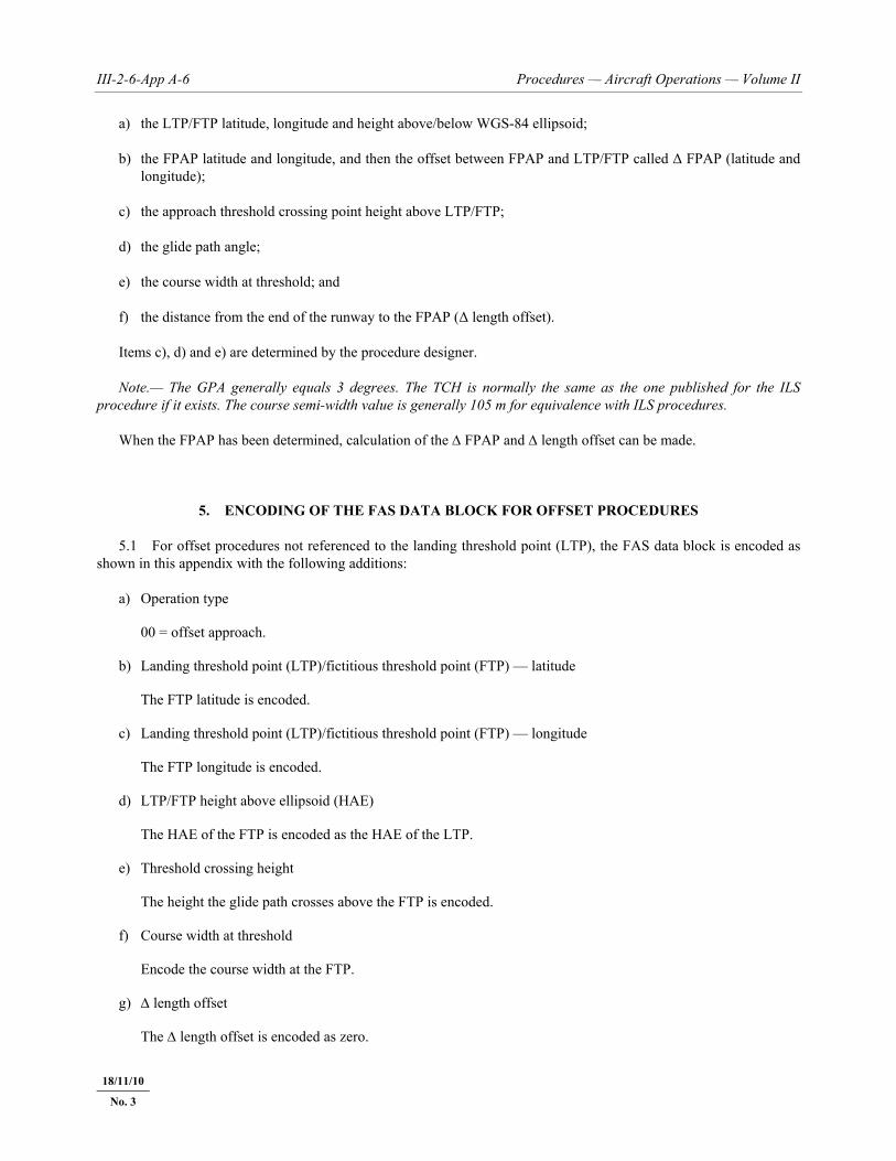
a) the LTP/FTP latitude, longitude and height above/below WGS-84 ellipsoid; b) the FPAP latitude and longitude, and then the offset between FPAP and LTP/FTP called Δ FPAP (latitude and
longitude); c) the approach threshold crossing point height above LTP/FTP; d) the glide path angle; e) the course width at threshold; and f) the distance from the end of the runway to the FPAP (Δ length offset). Items c), d) and e) are determined by the procedure designer. Note.— The GPA generally equals 3 degrees. The TCH is normally the same as the one published for the ILS procedure if it exists. The course semi-width value is generally 105 m for equivalence with ILS procedures. When the FPAP has been determined, calculation of the Δ FPAP and Δ length offset can be made.
5. ENCODING OF THE FAS DATA BLOCK FOR OFFSET PROCEDURES 5.1 For offset procedures not referenced to the landing threshold point (LTP), the FAS data block is encoded as shown in this appendix with the following additions: a) Operation type 00 = offset approach. b) Landing threshold point (LTP)/fictitious threshold point (FTP) — latitude The FTP latitude is encoded. c) Landing threshold point (LTP)/fictitious threshold point (FTP) — longitude The FTP longitude is encoded. d) LTP/FTP height above ellipsoid (HAE) The HAE of the FTP is encoded as the HAE of the LTP. e) Threshold crossing height The height the glide path crosses above the FTP is encoded. f) Course width at threshold Encode the course width at the FTP. g) Δ length offset The Δ length offset is encoded as zero.
18/11/10
No. 3
III-3-4-1 23/11/06 20/11/08
No. 2
Chapter 4
APV/BAROMETRIC VERTICAL NAVIGATION (BARO-VNAV)
Note 1.— Barometric vertical navigation (Baro-VNAV) is a navigation system that presents to the pilot computed vertical guidance referenced to a specified vertical path angle (VPA), nominally 3°. The computer-resolved vertical guidance is based on barometric altitude and is specified as a vertical path angle from reference datum height (RDH). Note 2.— APV/Baro-VNAV criteria provided in this chapter do not include procedure design criteria for RNP AR APCH procedures. Vertical obstacle clearance for APV/Baro-VNAV based on RNP AR APCH is predicated on a specific, well-defined vertical error budget (VEB). This VEB is not used in APV/Baro-VNAV criteria where different design criteria are applied. Note 3.— In this chapter, distances and heights related to obstacle clearance surfaces are all in SI units. Distances and heights are measured relative to threshold (positive before/above threshold, negative after/below threshold). If non-SI units are required, the appropriate conversions must be made as in the GBAS criteria (see Chapter 6).
4.1 GENERAL 4.1.1 This chapter describes the APV/Baro-VNAV criteria. The general criteria and Sections 1, 2 and 3, as amplified or modified by criteria in this chapter, apply. The criteria associated with the lateral navigation performance (LNAV) are based on the RNP APCH criteria detailed in Chapter 3. 4.1.2 Baro-VNAV approach procedures are classified as instrument procedures in support of approach and landing operations with vertical guidance (APV). They utilize a DA/H and not an MDA/H, and neither a FAF nor a missed approach point (MAPt) are identified. They use obstacle assessment surfaces similar to those for ILS, but based on the specific lateral guidance system. 4.1.3 Baro-VNAV procedures are used in association with LNAV-only procedures. The LNAV-only FAF and MAPt are used to define the areas but are not part of the VNAV procedure. 4.1.4 Baro-VNAV procedures shall not be authorized with a remote altimeter setting. Note.— A remote altimeter setting source may be charted for the associated LNAV-only procedure. 4.1.5 The construction of a Baro-VNAV procedure involves three steps: a) determination of VPA and final approach surface (FAS); b) construction of the APV-OAS; and c) calculation of the OCA/H based on obstacles penetrating the APV-OAS. 4.1.6 Annex 14 does not provide guidance on runway infrastructure requirements for approach and landing operations with vertical guidance. In order to assess whether the runway is suitable for an approach procedure with
18/11/10
No. 3

III-3-4-2 Procedures — Aircraft Operations — Volume II
23/11/06 20/11/08
No. 2
vertical guidance, that runway and associated OLS should at least meet the Annex 14 requirements for non-precision approach runway if the OCH is not less than 90 m (300 ft) and for Cat I precision approach runway if the OCH is lower than 90 m (300 ft).
4.2 STANDARD CONDITIONS Note.— Guidance on the approval process, aircraft requirements and aircraft system requirements for APV/Baro-VNAV operations can be found in the Performance-based Navigation (PBN) Manual, Volume II, Appendix A (Doc 9613). 4.2.1 Aircraft equipped with SBAS class 2, 3 or 4 avionics may use SBAS vertical guidance instead of baro vertical guidance when flying a Baro-VNAV procedure developed in accordance with this chapter. 4.2.2 Use of Baro-VNAV procedures developed in accordance with this chapter assume that a lower limit is applied to the OCA/H as follows: a) 75 m provided that the Annex 14 inner approach, inner transitional and balked landing surfaces have been
assessed and have not been penetrated; and b) 90 m in all other cases. 4.2.3 The optimum promulgated VPA shall be 3°; it shall not be less than 3° or greater than 3.5°. See 4.3.5.2.2, “Determination of minimum promulgated temperature”. 4.2.4 The reference datum height shall be 15 m (50 ft). 4.2.5 All obstacle heights are referenced to threshold elevation.
4.3 APV SEGMENT 4.3.1 General. The APV segment for Baro-VNAV is aligned with the extended runway centre line and contains the final descent segment for landing, and the initial, intermediate and final segments of the missed approach. 4.3.2 APV OAS. The APV OAS start at the final approach point (FAP) which is located at the intersection of the vertical path and the minimum height specified for the preceding segment. The FAP should not normally be located more than 19 km (10 NM) before the threshold. The APV OAS ends at the MAHF or MATF, whichever is first. The LNAV FAF and MAPt are primarily used to define the geometry of the areas and surfaces. Once the procedure has been designed, the FAF and MAPt of the associated LNAV procedure are used for database coding purposes and to define any underlying LNAV procedure (RNP APCH). 4.3.3 Relation of APV-OAS surface with LNAV criteria. The upper/outer edges of the APV-OAS side surfaces are based on the outer edges of the LNAV secondary areas. The lower/inner edges of the APV-OAS side surfaces are based on the edges of the LNAV primary area (see Figures III-3-4-1 to III-3-4-3). The outer edges of the side surfaces are as follows: a) MOCapp value above the inner edge for side surfaces attached to the FAS; b) 30 m above the inner edge for side surfaces attached to the intermediate missed approach surfaces; and
18/11/10
No. 3
Part III — Section 3, Chapter 4 III-3-4-3
23/11/06 20/11/08
No. 2
Note.— The height of the outer edge of the side surface joining the FAS to the intermediate missed approach surface will change from MOCapp value to 30 m throughout its length. c) 50 m above the inner edges attached to the final missed approach surface. 4.3.4 Frame of reference. See Chapter 6, 6.4.8.2, “Frame of reference”. 4.3.5 Definition of the OAS 4.3.5.1 The OAS are used to identify accountable obstacles and consist of the following surfaces: a) final approach surface (FAS); b) horizontal plane; and c) intermediate and final missed approach surfaces (Zi and Zf respectively). Each has associated side surfaces. Note.— The initial missed approach segment is contained within the calculation of the OAS Zi and Zf surfaces. 4.3.5.2 Final approach surface (FAS). The origin of the final approach surface is at threshold level and located at a distance before threshold equal to the point where the vertical path reaches a height of MOCapp above threshold, plus a longitudinal distance of 444 m (ATT). The final approach surface extends to the range of the nominal FAP + ATT with an angle as defined in 4.3.5.2.2. See Figure III-3-4-4. 4.3.5.2.1 The final approach surface is bounded laterally by the edges of the LNAV primary area. The inner edges of the associated side surfaces are defined by the edges of the LNAV primary area at the FAS elevation and the outer edges of the LNAV secondary areas MOCapp value above the FAS elevation. Note.— The calculation of VPA given a desired FAS (to eliminate a significant obstacle) is complicated by the interdependence of height at FAP, and temperature correction. Because of this, it is preferable to start the calculation with the optimum 3° VPA and calculate the associated FAS. If the FAS has to be raised to overcome significant obstacles, increase the VPA and/or reduce the height at the FAP until an optimum solution is found. 4.3.5.2.2 Determination of minimum promulgated temperature. Determine the minimum probable temperature (the temperature correction is obtained from Appendix A to this chapter) and round it down to the next lower 5°C increment. Then: a) the FAS for that temperature shall be calculated (see 4.3.5.2.3) and, if less than 2.5°, the promulgated VPA shall
be increased to ensure the FAS at minimum temperature is equal to or greater than 2.5°; and b) the length of the preceding segment shall be reviewed to ensure it meets the relevant requirements for minimum
distance before vertical path intercept. Note 1.— One suitable method of obtaining the minimum temperature is to obtain the mean low temperature of the coldest month of the year for the last five years of data at the aerodrome elevation. Round this temperature down to the next lower 5°C increment for promulgation. Obtain the cold temperature correction applicable for this temperature, the aerodrome elevation, and FAP height using the criteria in the appendix to this chapter.
III-3-4-4 Procedures — Aircraft Operations — Volume II
23/11/06 20/11/08
No. 2
Note 2.— No minimum temperature restrictions apply to aircraft with flight management systems incorporating final approach temperature compensation or to SBAS avionics within an SBAS coverage area. Note 3.— No minimum temperature restrictions apply to aircraft with flight management systems incorporating approved final approach temperature compensation, provided the minimum temperature is not below that for which the equipment is certificated. 4.3.5.2.3 Calculation of final approach surface angle and origin. The angle of the final approach surface (FAS) can be determined as follows:
tanαFAS = (height at FAP – temp. correction – MOCapp) × tan VPA
(height at FAP – MOCapp) The origin of the final approach surface at threshold level can be determined as follows:
XFAS = MOCapp - RDH
+ ATT tan VPA
The height of the final approach surface (hFAS) at range x relative to threshold can be determined as follows:
hFAS = (x – xFAS) × tan α FAS where: MOCapp = approach MOC RDH = reference datum height (m) ATT = along track tolerance (444 m) For temperature correction see Appendix A. 4.3.5.3 To protect aircraft equipped with vertical angular scaling, flying APV/Baro-VNAV procedures, an additional assessment of obstacles shall be made when the length of the final approach segment is greater than 9.26 km (5 NM). 4.3.5.3.1 Obstacle assessment. The additional assessment surface is derived from application of the W surface. When the final approach segment is longer than 9.26 km (5 NM), after the point where the W plane intersects the final approach surface, the W plane becomes the obstacle assessment surface in the primary area out to the FAP. The constants for calculation of the W surface are contained in the PANS-OPS OAS software. See Figures III-3-4-5 and III-3-4-6. 4.3.5.4 Horizontal plane. The horizontal plane is defined by a surface at threshold level bounded by the LNAV primary area between the origin of the FAS (see 4.3.5.2.3) and the origin of the missed approach surface. The lower/inner edges of the side surfaces are defined by the edges of the LNAV primary area at threshold level. The upper/outer edges of the associated side surfaces are defined by the outer edges of the LNAV secondary areas at the value of MOCapp above threshold at the origin of the FAS and the outer edges of the LNAV area 30 m above threshold at the origin of the intermediate missed approach surface at a distance Zi relative to threshold (positive before, negative after). Note.— Appendix B to this chapter provides the equations needed to calculate the height of any x, y location in these side surfaces given the four x, y coordinates and heights of the surface vertices. 4.3.5.5 Missed approach (Z) surfaces Note.— The criteria in this chapter assume that the RNAV system has the ability to change over to positive course guidance for missed approach in a timely manner, in order to allow the use of secondary areas.
18/11/10
No. 3
III-5-2-1 23/11/06 18/11/10
No. 3
Chapter 2
AERONAUTICAL DATABASE PUBLICATION REQUIREMENTS
2.1 For RNAV standard departure procedures — instrument (SID), the following data shall be published in tabular form or a formal textual description on the verso of the chart or a separate, properly referenced sheet (see Annex 4, 9.9.4.3): a) procedure designator; b) required navigation performance or basis for the approval applicable to the procedure; c) unambiguous description of the path and the method of termination of each specified segment; d) names, coded designators or name-codes and the geographical coordinates in degrees, minutes, seconds, and
tenths of seconds, of all significant points defining the route, including annotation as to whether the significant point is fly-by or flyover;
e) geodesic distance to the nearest tenth of a kilometer or tenth of a nautical mile between each successive
designated significant point; f) true track to the nearest tenth of a degree and magnetic track to the nearest degree between each successive
significant point; g) upper and lower altitude limit at a significant point, to the nearest higher 50 m or 100 ft/flight level, as
applicable; h) speed limit at a significant point, expressed in units of 10 knots, as applicable; i) remarks; and j) associated RNAV holding procedure data including: 1) holding identification (if any); 2) holding fix (navigation aid) or waypoint with geographical coordinates in degrees, minutes, seconds, and
tenths of seconds; 3) inbound true track to the nearest tenth of a degree and magnetic track to the nearest degree; 4) maximum indicated air speed expressed in units of 10 knots; 5) minimum and maximum holding level to the nearest higher 50 m or 100 ft/flight level; 6) time/distance to the nearest tenth of a kilometre or tenth of a nautical mile outbound; and 7) direction of the turn.
III-5-2-2 Procedures — Aircraft Operations — Volume II
23/11/06 18/11/10
No. 3
2.2 For RNAV standard arrival procedures — instrument (STAR) the following data shall be published in tabular form or a formal textual description on the verso of the chart or a separate, properly referenced sheet (see Annex 4, 10.9.4.3): a) procedure designator; b) required navigation performance or basis for the approval applicable to the procedure; c) unambiguous description of the path and the method of termination of each specified segment; d) names, coded designators or name-codes and the geographical coordinates in degrees, minutes, seconds, and
tenths of seconds, of all significant points defining the route, including annotation as to whether the significant point is fly-by or flyover;
e) geodesic distance to the nearest tenth of a kilometer or tenth of a nautical mile between each successive
designated significant point; f) true track to the nearest tenth of a degree and magnetic track to the nearest degree between each successive
significant point; g) upper and lower altitude limit at a significant point, to the nearest higher 50 m or 100 ft/flight level, as
applicable; h) speed limit at a significant point, expressed in units of 10 knots, as applicable; i) vertical path angle to the nearest one one-hundredth of a degree, as applicable; j) remarks; and k) associated RNAV holding procedure data including: 1) holding identification (if any); 2) holding fix (navigation aid) or waypoint with geographical coordinates in degrees, minutes, seconds, and
tenths of seconds; 3) inbound true track to the nearest tenth of a degree and magnetic track to the nearest degree; 4) maximum indicated air speed expressed in units of 10 knots; 5) minimum and maximum holding level to the nearest higher 50 m or 100 ft/flight level; 6) time/distance to the nearest tenth of a kilometre or tenth of a nautical mile outbound; and 7) direction of the turn. 2.3 For RNAV instrument approach procedures, the following data shall be published in tabular form or a formal textual description on the verso of the chart or a separate, properly referenced sheet (see Annex 4, 11.10.9): a) procedure designator; b) required navigation performance or basis for the approval applicable to the procedure;
Part III — Section 5, Chapter 2 III-5-2-3
18/11/10
No. 3
c) unambiguous description of the path and the method of termination of each specified segment; d) names, coded designators or name-codes and the geographical coordinates in degrees, minutes, seconds, and
tenths of seconds, of all significant points defining the route, including annotation as to whether the significant point is fly-by or flyover;
e) geodesic distance to the nearest tenth of a kilometer or tenth of a nautical mile between each successive
designated significant point; f) true track to the nearest tenth of a degree and magnetic track to the nearest degree between each successive
significant point; g) upper and lower altitude limit at a significant point, to the nearest higher 50 m or 100 ft/flight level, as
applicable; h) speed limit at a significant point, expressed in units of 10 knots, as applicable; i) final approach vertical path angle to the nearest one one-hundredth of a degree; j) threshold crossing height to the nearest foot, as applicable; k) remarks; and l) associated RNAV holding procedure data including: 1) holding identification (if any); 2) holding fix (navigation aid) or waypoint with geographical coordinates in degrees, minutes, seconds, and
tenths of seconds; 3) inbound true track to the nearest tenth of a degree and magnetic track to the nearest degree; 4) direction of the turn; 5) maximum indicated air speed expressed in units of 10 knots; 6) minimum and maximum holding level to the nearest higher 50 m or 100 ft/flight level; and 7) time/distance to the nearest tenth of a kilometer or tenth of a nautical mile outbound.
___________________

�������