airconditioning - indian...
TRANSCRIPT
___________________________________________________________________________
AIRCONDITIONING
CONTENTS
CHAPTER No.
SUBJECT PAGE
01. Airconditioning Fundamentals 01
02. Comfort Airconditioning 11
03. Performance Characteristics of AC Systems 16
04. Heat Load calculations 18
05. Airconditioning of Railway Coaches 23
06. Roof Mounted A C Package Units for Railway Coaches
40
07. AC 3 Tier Sleeper Coaches 46
08. Airconditioning of LHB coaches 49
09. Rake Links 57
10. Airconditioning of Other Installations 60
________________________________________________________________________

___________________________________________________________________________
1. AIRCONDITIONING FUNDAMENTALS
1.0. BASIC TERMINOLOGIES
1.0.1 Kilo-Calorie It is defined as the amount of heat to be added (removed) to raise (lower) the temperature of one Kg of water by one degree celesius.
1.0.2 BTU It is defined as the amount of heat to be added (removed) to raise (lower) the temperature of one pound of water by one degree Fahrenheit. 1 Kilo - calorie = 3.97 BTU
1.0.3 Sensible heat It is that heat which when applied to a body, results in a rise of its temperature. It is the heat which is sensed by a thermometer.
1.0.4 Latent heat It is that heat which when applied merely changes the state of substance, whether solid, liquid or, gas, without causing any change in its temperature. Latent heat of fusion of ice 80 k.cal/kg. (144 BTUs/Ib) Latent heat of evaporation of water 538.75 k.cal/kg (970 BTUs/lb)
1.0.5 Enthalpy It is a calculated property of vapour which is defined as "Total heat content". It is the sum of the sensible heat" and latent heat. '
1.0.6 Critical temperature (Tc) There is a certain temperature for every liquid or gas, which is called its critical temperature. When a gas is above its critical temperature, any amount of increase in pressure cannot liquify it. When the temperature is below its critical point, the gas can be liquified without lowering its temperature, by merely increasing the pressure.
1.1 TEMPERATURE AND PRESSURE RELATIONSHIP Water boils at 100°C when the pressure on it is atmospheric. If the pressure is increased to above atmospheric, the boiling point increases and if the pressure is decreased to below atmospheric, the boiling point decreases. Boiling water does not necessarily have to be hot, because if there is vacuum over the surface of the water, it will boil at a very low temperature. The same thing is true in regard to other liquids such as, the various refrigerants which are used to produce low temperatures. These refrigerants have the same properties as
________________________________________________________________________
___________________________________________________________________________
water except that the range of their boiling points is lower
1.2 PSYCHROMETRY The measurement of moisture content in air is known as Psychrometry. The air is mainly a mixture of dry air and water vapour. The relative amount of water vapour in the atmosphere is very small, variations in this amount as well as changes in temperature are very significant and important in airconditionmg. The following terms are in use in study of air-vapour mixture.
1.2.1 Dry Bulb Temperature (DBT) It is the temperature of air as measured by an ordinary thermometer.
1.2.2 Wet Bulb Temperature (WBT) It is the temperature of air as measured by an ordinary thermometer, whose glass bulb is covered by a thin cotton sleeve soaked in water. When the sleeve is wetted, mercury column of the thermometer will be observed to start dropping down, until it finally settles down at a definite minimum value. This is because the water in the WB takes away its latent heat, as it gets vapourised from the mercury in the bulb as a result of which the bulb gets cooled and the mercury column shows a low temperature. The drop in the temperature depends upon the relative humidity of the surrounding air. When air is heated, the DB increases; WB also increases, but at a slower rate and therefore, the difference between DB and WB widens indicating a lower humidity. When air is cooled, it becomes more and more humid, until it becomes fully saturated and the difference between DB and WB goes on getting reduced until it is zero at saturation. At saturation DB and WB are equal. If cooling is continued further some of the moisture contained in the air gets thrown out and will condense, since air has only a limited holding capacity for water vapour.
1.2.3 Dew Point Temperature (DPT) It is the temperature of air at which the moisture of air starts condensing on the surface. The relative humidity at dew point is 100%.
1.2.4 Effective Temperature (ET) It may be defined as an arbitrary index that combines into single factor the effect of temperature, humidity and air movement on human comfort in a noise free environment. This corresponds to a DB temperature of saturated air at which a given percentage of people feel comfortable. Thus an effective temperature of 21°C can be expressed as 23°C DB at 70% RH or 25°C DB at 30% RH.
________________________________________________________________________
___________________________________________________________________________
2. COMFORT AIR CONDITIONING
2.0 SYNOPSIS Air conditioning which deals with the comforts of human beings in an enclosed conditioned space is known as Comfort Air Conditioning There are a number of factors that influence the comfort conditions. The effect of all these factors individually and collectively have been discussed in this paper
2.1 INTRODUCTION The term 'Air Conditioning' was coined by Mr. S.W. Cramer in 1906 while he was making efforts in putting the air in a fit condition for the textile industry. The term has since come into use in its broader sense implying control of any or all of the physical or chemical properties of air within any enclosure.
Comfort airconditioning has been defined by Dr. D.W. Carrier as under:
“Artificial simultaneous control within enclosures of variable humidity, temperature, air motion and air cleanliness.” Odour control is another factor concerning comfort which has been subsequently included in the above definition.
Any change in these conditions results in a change in the physiological functions of the body and the body tries to adjust itself to the changing outside conditions. The performance of adjustments takes time and sensation of comfort or discomfort would depend upon the quick or slow adjustment. Often the adjustment may not be reached with consequent increase in discomfort.
2.2 WHAT IS COMFORT ? Comfort is a subjective quantity related to the ease with which an individual maintains a thermal balance between, himself and the environment. As such, feeling of great satisfaction with surrounding conditions may provide physical comfort. But human beings are complex in nature and feeling of comfort in them may depend upon state of mind, physical condition and state of activity. Moreover, feelings of individual comfort may differ for the same individual at different times. It may depend upon degree of acclimatization or even dress. So a compromise regarding the average standard of comfort and the individual characteristics has to be made. This compromise should be on the side of actual natural conditions prevailing at a time, to make the process of conditioning cheaper. These standards have been adopted based partly on experience and partly on tests conducted on individual.
________________________________________________________________________

___________________________________________________________________________
3. PERFORMANCE OF AIR-CONDITIONING SYSTEMS
3.0 INTRODUCTION Net refrigerating effect, KW per ton of refrigeration and C.O.P are of extreme importance in the design and operation of A.C. systems. The value of these factors depends on the refrigerant used, efficiency of the components and the temperatures of evaporator and condenser.
3.1 REFRIGERATING EFFECT The quantity of heat that each Kg of refrigerant absorbs from the refrigerated space is known as the refrigerating effect, For example, when one Kg of ice melts, it absorbs from the surrounding air and adjacent objects an amount of heat equal to its latent heat of fusion. If the ice melts at 0°C, it will absorb 80 K. cal/kg, so the refrigerating effect of 1 kg of ice is 80 K. cal. While selecting a refrigerant, care must be taken to ensure that it has better refrigerating effect.
3.2 EFFICIENCY OF REFRIGERATING MACHINE A refrigerating machine is a reversed heat engine and similar principles of efficiency are involved in both. The efficiency of a heat engine operating on carnot cycle between temperature limits T1 and T2 is given by the following formula.
T1 – T2 Efficiencyc = ——————— Where, Ts are in ° kelvin. T1
Since the refrigerating machine is a reversed heat engine theoretical carnot efficiency for a refrigerating machine is given by the following formula.
T2 Efficiencyc = ——————— T1 – T2
Where, T1 is the condenser temperature (absolute) T2 is the evaporator temperature (absolute)
3.3 CO-EFFICIENT OF PERFORMANCE ( C.O.P.) The co-efficient of performance of a refrigerating cycle is an expression of the cycle efficiency and is stated as the ratio of the heat absorbed in the refrigerated space to the equivalent heat energy supplied to the compressor.
Heat absorbed from the refrigerated space C.O.P. = ——————————————————————— Equivalent heat energy supplied to the compressor.
________________________________________________________________________

___________________________________________________________________________
3.4 KW PER TON RATIO A measure of refrigerating machine efficiency that has been used is KW per ton. On an actual performance test under "standard" conditions for the type of service intended, the net output cooling rate in K. Cal / hr. is determined The average KW input to the machine during the test is also measured. The KW per ton ratio (KW/ton) is then calculated.
3.5 ENERGY EFFICIENCY RATIO (E.E.R.) A recently popular measure of efficiency, especially for unitary conditioners of small to medium capacity is the ratio K.Cal per hour per watt (K.cal/hr-W). This measure is called the "Energy efficiency ratio" (E.E.R.). The average cooling capacity of the unit is determined by a test run under standard conditions. The average power input to the condensing units in watts is measured. From this data the E.E.R. can be calculated by using the following formula.
K.cal/Hr cooling rate E.E.R. = ——————————— Watts input
-------------------------------
________________________________________________________________________

___________________________________________________________________________
4.0 HEAT LOAD CALCULATION OF AC 2T
SLEEPER COACH AC airconditioned coach has to work under widely varying conditions of ambient temperature, latitude, passenger load etc. In deciding the capacity of the plant, certain assumptions regarding number of adverse conditions of the working are to be made and based on these assumptions the plant capacity required is worked out.
RDSO specification No. TRC-1-72 stipulates certain standard comfort conditions, volume of fresh air required per passenger per minute, coefficient of heat transfer for various parts of the coach etc.
Data and constants used and the assumptions made are,
ABBREVIATIONS : T.D = Amb. Temp. diff. T.D.S = Solar Temp. diff. K = Coefficient of heat 'transfer-K cal/Hr/m2/°C U = Coefficient of heat transfer for window due to solar heat gain. G.D. = Grains difference.
COEFFICIENT OF HEAT TRANSFER (k) in k-Cal/Hr/m2/°C For, Wall and end partitions = 0.615 Roof = 0.65 Floor = 0.72 Window (Conduction) . = 1.94 'U' for window = 5.34
The internal temperature in relation to the outside temperature and relative humidity to be maintained when operated with full compliment of'46 passengers, lighting and fan load etc.
DBT WBT RH Moisture grains.
°C °C % *
Outside conditions 45 25 -- 82
Inside conditions 25 ~ 40 56
T.D. = 20 G.D. = 26
________________________________________________________________________

___________________________________________________________________________
T.D. for end portions is always considered to be 3°C less than T.D. for other parts of the coach, since non-airconditioned space adjacent to the airconditioned compartments is considered to have a temperature of 3°C less than the ambient temperature.
Solar Temp.Difference (TDS) Side wall = 9° C Roof = 10.55°C Window = 95.55°C
Requirement of fresh air for non-smoking compartments
= 0.35m3 /passenger/ minute.
Quantity of ventilating air for 46 passengers (Q)
0.35x46 = 16.1 m3 / minute 16.1x35.3 = 568.33 Ft3 / minute(CFM)
The following are the wattages considered for various-electrical appliances. 2 Flourescent tube light - 24 W.
Eventhough the wattage of the tube is 20 W, the choke also consumes energy. Hence, 1.2 times the wattage i.e. 1+2 x 20 = 24W has been considered for the purpose of heat load calculations. Incandescent lamps = 15W Carriage Fan = 29W
DATA COLLECTED FROM A.C. MANUAL Heat transfer from equipments and fans = 2545 BTU/HP/Hr Heat transfer from fluorescent lights and = 3.4 BTU/Watt/Hr. incandescent lamps Sensible heat per passenger = 205 BTU/Hr. (51.6 K.Cal/Hr) Latent heat per passenger = 195 BTU/Hr (49.12K.CaI/Hr) 1 Ton of refrigeration = 12000 BTU/Hr. (3024 K.Cal/Hr) 1 k-calorie = 3.97 BTU/Hr.
DIMENSIONS OF A.C. PORTION OF COACH - Length of AC portion (A) = 15.2 M Width of roof (B) = 3.245 M Width of floor (C) = 3.04 M Height of A.C. portion (D) = 2.03 M Area of side wall (A x D) = 30.856 M2
Area of roof (A x B) = 49.324 M2
Area of floor (A x C) = 46.208 M2
________________________________________________________________________
___________________________________________________________________________
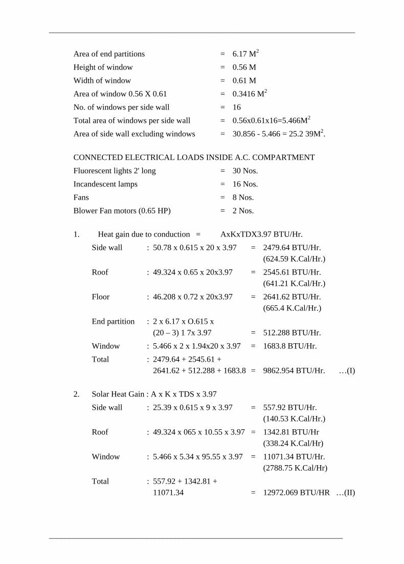
Area of end partitions = 6.17 M2
Height of window = 0.56 M Width of window = 0.61 M Area of window 0.56 X 0.61 = 0.3416 M2
No. of windows per side wall = 16 Total area of windows per side wall = 0.56x0.61x16=5.466M2
Area of side wall excluding windows = 30.856 - 5.466 = 25.2 39M2.
CONNECTED ELECTRICAL LOADS INSIDE A.C. COMPARTMENT Fluorescent lights 2' long = 30 Nos. Incandescent lamps = 16 Nos. Fans = 8 Nos. Blower Fan motors (0.65 HP) = 2 Nos.
1. Heat gain due to conduction = AxKxTDX3.97 BTU/Hr. Side wall : 50.78 x 0.615 x 20 x 3.97 = 2479.64 BTU/Hr. (624.59 K.Cal/Hr.) Roof : 49.324 x 0.65 x 20x3.97 = 2545.61 BTU/Hr. (641.21 K.Cal/Hr.) Floor : 46.208 x 0.72 x 20x3.97 = 2641.62 BTU/Hr. (665.4 K.Cal/Hr.) End partition : 2 x 6.17 x O.615 x (20 – 3) 1 7x 3.97 = 512.288 BTU/Hr. Window : 5.466 x 2 x 1.94x20 x 3.97 = 1683.8 BTU/Hr. Total : 2479.64 + 2545.61 + 2641.62 + 512.288 + 1683.8 = 9862.954 BTU/Hr. …(I)
2. Solar Heat Gain : A x K x TDS x 3.97 Side wall : 25.39 x 0.615 x 9 x 3.97 = 557.92 BTU/Hr. (140.53 K.Cal/Hr.) Roof : 49.324 x 065 x 10.55 x 3.97 = 1342.81 BTU/Hr (338.24 K.Cal/Hr) Window : 5.466 x 5.34 x 95.55 x 3.97 = 11071.34 BTU/Hr. (2788.75 K.Cal/Hr) Total : 557.92 + 1342.81 + 11071.34 = 12972.069 BTU/HR …(II)
________________________________________________________________________

___________________________________________________________________________
3 Heat gain due to passengers (BTU/Hr.)
S.H. = 205 x No. of passengers.
L.H. = 195 x No. of passengers.
S.H + L.H = 400 X No. of passengers. = 400 x 46 = 18400 BTU/Hr. …(III) = (4634.76 K.Cal/Hr)
4. Heat gain due to ventilation (BTU/Hr.) =
S.H. = 1.08 x Q x TD x 9/5 = 1.08 x 568.33 x 20 x 9/5 = 22096.67 BTU/Hr. = (5565.91 K.Cal./Hr)
L.H. = 0.68 x Q x Gd = 0.68 x 568.33 x 26 = 10048.07 = (2531 K.Cal./Hr)
Total = 22096.67 + 10048.07 = 32144.7 BTU/Hr … (IV) = (8096.91 K.Cal./Hr)
5. Heat gain due to elect, appliances = Wattagex3.4 BTU/Hr. or, H.P. x 3600 BTU/Hr.
Flouroscent Light 20W = (20 x 1.2) W. = 1.2 x 20 x 3.40 x 30 = 2448 BTU/Hr. = (616.62 K.Cal./Hr)
Incandescent lamps = 15 x 16 x 3.40 = 816 BTU/Hr. = (205.54 K.Cal/Hr)
Fan = 29W x 8 x 3.4 = 788.8 BTU/Hr. = (198.69 K.Cal./Hr)
Blower fan = 0.65HP x 2 x 2545 = 3308.5 BTU/Hr = 833.37 K.Cal./Hr
Total = 2448 + 816 + 788.8 + 3308.5
________________________________________________________________________

___________________________________________________________________________
= 7361.3 BTU/Hr. = 1854.22 K.Cal / Hr …(V)
Total of l + II + III + IV + V = 80741 023 BTU/Hr (20337.78 K.Cal/Hr) Heat gain due to infiltration @ 10% = 8074.1 BTU/Hr. = (2033.78 K.Cal./Hr) Gross Total Heat gain = 81003 07 - 8100.3 = 88815 BTU/Hr. = 22371.56 K.Cal./Hr 88815 Refrigeration capacity (TR) = ————— = 7.4 TR 12000 22371.56 = ————— = 7.4 TR 3024
----------------------------
________________________________________________________________________

___________________________________________________________________________
5. AIRCONDITIONING OF RAILWAY COACHES
5.0 INTRODUCTION Passengers in a railway travel are adversely affected by infiltration of air unpleasantly laden with dust due to open windows. This is more so in case of high speed passenger carrying trains. Secondly for a tropical country like India, the temperature varies from 46 degree C during summer to 2 degree C during winter. Airconditioning of railway coaches is, therefore, necessary for the maximum comfort and well being of passengers in a railway travel. In keeping with modern trend, airconditioning of coaches for upper class travellers and lately even for lower class travellers has been introduced by the Indian Railways.
5.1 SPECIAL PROBLEMS FACED IN RAIL AIRCONDITIONING As compared to the normal buildings, Air conditioning of Railway coaches poses the following additional problems: • Requirement of very high reliability standard. • Equipment should be light in weight. • Equipment should take minimum space. • Available power, generally at 110V D.C. has to be utilised. 415 V, 50 Hz, 3 Ph,
industrial power is available only on a few nominated trains like Rajdhani and Shatabdi Express. However, in such cases, the flexibility of attaching and detaching coaches is lost.
• Due to large number of passengers in small space, the space left for air circulation is limited.
• In the Railway coaches, where people move in and out at all hours of the day, to sudden changes in temperature, which may cause chill or heat are to be avoided.
• Rapidly changing ambient conditions as the train moves from one part of the country to another.
• Excessive vibrations. • Dusty atmosphere. • Vandalism and abuse. • Flying ballast hitting the equipment. • Safety of passengers and trains. • Dirty environment for the maintenance staff. • Restricted time available for maintenance. All these problems have to be solved,' within a comparatively small outlay, so that
________________________________________________________________________

___________________________________________________________________________
airconditioned travel can become more common
5.2 REQUIREMENTS OF RAILWAY COACH AIRCONDITIONING SYSTEM • Supplying clean fresh air at a controlled uniform temperature. • Catering, within the confines of the Railway carriages to the continuously
changing number of passengers. • Providing for heating as well as cooling on a train that travels through areas of
widely differing climate during its journey. • Operation of the equipment from power generated, stored and controlled on the
train.
5.3 CLASSIFICATION OF AIRCONDITIONED COACHES SG Coaches EOG Coaches BG MG ` AC AC AC Compo 1st AC 2T 3T 2T Chair site ACC Car AC AC AC 1st Pantry Dining Power 3T 2T Chair ACC Car Car Car
5.4 DESCRIPTION OF POWER SUPPLY 5.4.1 SG Coaches The electrical power for the self generating type of coaches is derived from the alternator mounted on bogie transom of the coach and driven by the axle through 'V belt drive as long as the coach is in motion at the minimum full load output (MFO) speed of the alternator. During stationary or when the coach is running at less than MFO speed the entire coach load is met by the battery of 800 AH capacity. Provision for charging and precooling the coach from external supply has been made by means of battery charger, 200A rating mounted on the coach under frame. Two numbers of 415 V, 3 ph, ac, precooling sockets have been provided diagonally on the end walls. The alternator working in association with rectifier cum regulator gives an output of 18 KW at 130 V, DC in the underslung type of AC coach, whereas the alternator capacity is 25Kw in the RMPU AC coach. One alternator set per AC plant has been fitted in the self generating type AC coaches. 5.4.2 EOG Coaches
________________________________________________________________________
___________________________________________________________________________
The electrical power supply for end on generation type AC coaches is derived from separate generator cars marshalled at the ends of the train formation, with generation and transmission voltage of 415 V, 3 ph, AC. The power for individual coaches is tapped by means of rotary switch from any one of the double feeders running along the coach leading from the power cars, and coupled between coaches by means of inter-vehicular couplers. The airconditioning equipment works at 415V, 3 phase AC supply and train lighting equipment work at 110V, AC, obtained between phase and neutral derived from a 3 KVA,415/190V, 4 wire step down transformer.
5.5 DRIVING EQUIPMENTS Driving equipments consist of motors for driving the compressor, condenser impeller fans and the evaporator blower fans. The driving motors in self generating type coaches are all of D.C. machines needing more care for attention of commutator and brushes. The E.O.G. type coaches are provided with 3 phase AC squirrel cage induction motors for driving the AC equipments.
5.6 DETAILS OF BATTERIES PROVIDED ON S.G. COACHES (UNDER SLUNG TYPE)
Type of AC Coach No. of sets & capacity of battery
Relevant BIS specification
BG AC 2T Sleeper 1 set of 800 AH (56 cells) IS ; 6848
BG AC Chair Car - do - - do -
BG AC composite - do - - do -
BG.ACC. 1st class. 1 set of 525 AH - do -
MG.AC. 2T sleeper 1 set of 450 AH - do -
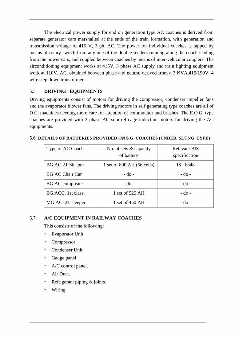
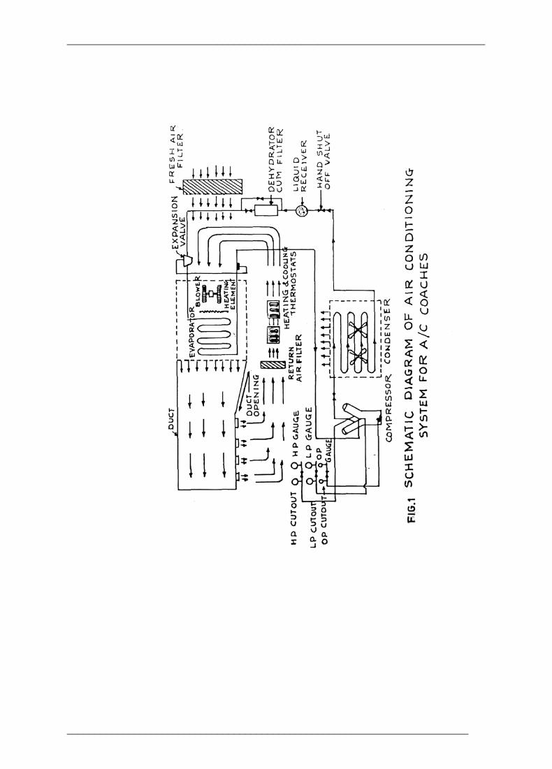
5.7 A/C EQUIPMENT IN RAILWAY COACHES This consists of the following: • Evaporator Unit. • Compressor. • Condenser Unit. • Gauge panel. • A/C control panel. • Air Duct. • Refrigerant piping & joints. • Wiring.
________________________________________________________________________
___________________________________________________________________________
________________________________________________________________________

___________________________________________________________________________
________________________________________________________________________
___________________________________________________________________________
________________________________________________________________________

___________________________________________________________________________
________________________________________________________________________

___________________________________________________________________________
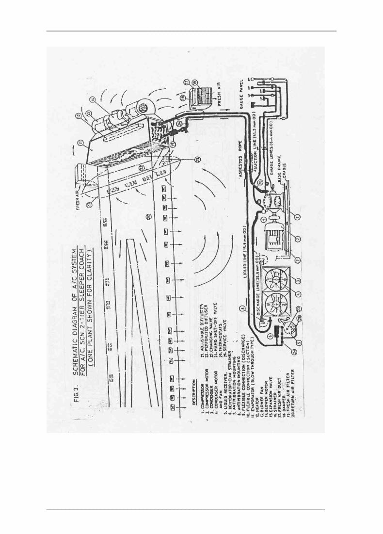
5.7.1 Evaporator Unit The evaporator unit consists of a thermostatic expansion valve, a heat exchanger, a resistance heating unit and centrifugal blower driven by a motor The thermostatic expansion valve controls quantity of high pressure liquid refrigerant and allow to expand to a lower pressure corresponding to the load demand The expanded refrigerant passes through the distributor into the heat exchanger consisting of finned copper tubes. The return air from the air conditioned compartment (75 %) is mixed with fresh air (25%) and this mixture is drawn/blown through the heat exchanger, where heat in the air is transferred to the cool refrigerant causing cooling of the air and the evaporation of the refrigerant inside the tubes. The cooled air is led through the ducting to the various compartments and diffused by means of air diffusers Filters are provided in the fresh air and return air path to eliminate dust. When the outside ambient temperature is very low, heater is switched on according to the setting of the thermostats.
5.7.2 Compressor The refrigerant vapour drawn from the evaporator is compressed by means of a multi cylinder reciprocating compressor and compressed to a pressure ranging from 10 to 15 Kg/Cm2 according to the load demand. The work done due to compressor raises the temperature of the refrigerant vapour.
5.7.3 Condenser The condenser serves the function of extracting the heat absorbed by the refrigerant vapour in the evaporator and the heat absorbed during the compression process. The condenser consists of a heat exchanger, which is forced-air-cooled by means of two or three axial flow impeller fans. The refrigerant vapour is liquified when ambient cool air is passed through the heat exchanger. The refrigerant liquid leaving the condenser is led into the liquid receiver from where it proceeds to the expansion valve on the evaporator. The liquid receiver is a cylindrical container which contains a reserve of the refrigerant liquid. A dehydrator and filter are also provided to ensure that the refrigerant is free from moisture and dust particles.
5.7.4 Gauge panel Gauge panel consists of pressure gauges (HP, LP, and OP) and pressure cutouts to protect the compressor against, (i) High pressure, (ii) Low pressure and (in) low oil pressure.
5.7.5 High pressure cutout It is a safety device against build up of excessive delivery pressures and protects the compressor and piping system from damage. It is a pressure operated switch which switches off the compressor drive motor when the pressure exceeds a preset value ( 17.6 Kg/Cm2). The plant can not be restarted unless the cutout is reset manually. 5.7.6 Low pressure cutout
________________________________________________________________________

___________________________________________________________________________
It is also a pressure operated switch similar to the H.P. cutout switch, but it shuts down the compressor if the suction pressure drops down below 0.7 Kg/Cm2. It protects the system against unduly low evaporator temperatures and formation of frost on the evaporator. No manual reset is provided on this and therefore the compressor starts automatically if the suction pressure rises above the preset value.
5,7.7 Low oil pressure cutout It ensures adequate lubrication of compressor to avoid piston seizure due to less lubricating oil or failure of oil pump. This cutout is set at 2.5 Kg/Cm2.
5.7.8 A/C control panel The control of the airconditioning system is achieved by means of air conditioning control panel. The design of the various elements in the control panel takes into account the system safety requirements. The safety requirements for the operation of the A/C system are listed as under: a. The working of blower fan of the evaporator and the blower fan of the
condenser have to be ensured before the compressor starts functioning. b. Suitable protection to ensure adequate lubrication of compressor to avoid
piston seizure. c. The excessive pressure on the discharge side of the compressor (High Head
Pressure) should be avoided. d. The suction pressure should not be lower than 0.7 Kg/Cm2 to prevent frosting
of the evaporator. e. The compressor motor has to be soft started to limit the sudden in rush of
starting current. f A suitable interlock has to be provided to ensure that heater is not on, when
the compressor is working. g A low voltage protection for compressor motor to ensure that voltage does not
go below 100 volts in order to avoid undue drain on battery. h. The blower fan has to come 'ON’ before the heater comes 'ON'. Over load
protection and short circuit protection for all electrical circuits. The A/C control panel incorporates all the above safety requirements.
5.7.9 Air duct The air conditioning system includes three air ducts as follows: a. Fresh (Inlet) air duct. b. Main air duct. c. Return air duct. Actually there is no separate return air duct provided in A/C coaches. In the case of
________________________________________________________________________
___________________________________________________________________________
a.c. two tier coach and A.C. chair car, the return air is drawn through the return air filters directly from the nearest compartment In 1st class A.C. coach, the corridor acts as return air duct and the return air is drawn through return air filters located at the corridor ceiling near the first compartment.
Fresh (Inlet) air duct This is provided at the rate of two per AC plant. It is mounted on the side wall just
________________________________________________________________________
___________________________________________________________________________
below the roof evaporator unit. There is an opening in the side wall with louver hinge door arrangement and with the provision to house a fresh air filter. The fresh (inlet) air duct has been designed with damper valve to control the quantity of fresh air to be drawn into the compartment. This arrangement has been standardised for all types of air conditioned coaches
Main air duct The conditioned air from the evaporator unit is blown into the main air duct by means of two centrifugal blower fans driven by a motor with double extended shaft, The air is distributed to each compartment in the case of 2 tier sleeper coach and full AC first class coach through adjustable diffusers. In the case of a c chair cars, the conditioned air from the main air duct is distributed along the hall through longitudinal apertures suitably set at factory. The main air duct has been provided with central diagonal partition making it two independent taper ducts so that each compartment is influenced by the diffused air of both plants. Further air distribution to the entire compartment is maintained at constant velocity. The cross section of the main air duct has been designed in such a way that air velocity inside the duct shall not be higher than 350 metre/min. in order to reduce turbulence and noise due to air motion in the duct. For the same reason the main air duct has been connected to evaporator outlet by means of an intermediate transition duct made of fire resistant canvas to prevent transmission of noise produced by the blower unit- The aperture of air diffuser has been designed to deliver the required quantity of air into the compartment at a velocity not greater than 250M/min. This diffuser is provided with a knob to deflect the air to the required angle. By the above arrangement the air velocity inside the compartment obtained is between 6M/min. to 12M/min. (0.1 M/sec. to 0.2M/sec.) at the face level of the passenger.
5.7.10 Refrigerant piping and joints The refrigerant piping consists of the suction line (from the evaporator out let to compressor inlet) discharge line (from compressor outlet to condenser inlet) and liquid line (from the liquid receiver to the inlet side of expansion valve), connections to the gauge panel from the compressor delivery side (high pressure side), low pressure side and from the compressor crank case. The lubricating oil connections are also part of the piping system Only copper pipes to specification BS:2017-63, C-106 Sec - 3 are used. Main pipelines are jointed with couplers or elbows by means of silver brazing where as joints to various components like gauges pressure cutouts, hand shut off valves, expansion valve, strainer etc. are connected by means of flare joints to facilitate easy removal of the above elements for replacement and inspection. 5.7.11 Wiring
________________________________________________________________________
___________________________________________________________________________
All wiring has been done by means of multistranded PVC insulated copper cables to specification. ICF/Elect./857. All cables have been laid on steel trough/conduits for easy maintenance and prevent fire hazards. Crimped type of connections have been adopted throughout. All the terminal boards are of fire retardant FRP material, Reliability of wiring has been made very high.
5,7.12 Temperature setting
The temperature inside the airconditioned compartment is controlled by mercury in glass thermostats with different settings as mentioned below. Operation of cooling or heating takes place in accordance with ambient conditions.
The temperature control thermostats are fitted in the return air passage. Two types of thermostats are used, one for controlling the cooling and the other for controlling the heating. Both these thermostats are alike, each consisting of a sealed glass tube containing a column of mercury. Presently there are two settings for cooling at 25OC and 23OC and for heating at 21OC and 19OC respectively. The mercury thermostats are being replaced by electronic thermostat with one setting each for cooling at 24OC and for heating at 20OC.
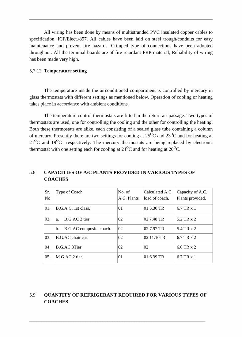
5.8 CAPACITIES OF A/C PLANTS PROVIDED IN VARIOUS TYPES OF COACHES
Sr. No
Type of Coach.
No. of A.C. Plants
Calculated A.C. load of coach.
Capacity of A.C. Plants provided.
01. B.G.A.C. 1st class. 01 01 5.30 TR 6.7 TR x 1
02. a. B.G.AC 2 tier. 02 02 7.48 TR 5.2 TR x 2
b. B.G.AC composite coach. 02 02 7.97 TR 5.4 TR x 2
03. B.G.AC chair car. 02 02 11.10TR 6.7 TR x 2
04 B.G.AC.3Tier 02 02 6.6 TR x 2
05. M.G.AC 2 tier. 01 01 6.39 TR 6.7 TR x 1
5.9 QUANTITY OF REFRIGERANT REQUIRED FOR VARIOUS TYPES OF COACHES
________________________________________________________________________

___________________________________________________________________________
Sr.No.
Type of Coach. No. of AC Plants
Plant capacity (TR)
Types of Compressor
Quantity Refrigerant (kg.)
5F30
5F40
5F60
SMC.4.65
01. 1CF built full AC Coaches
One 5to9
FK4.
1x15 (approx.)
5F30
5F40
5F60
SMC.4.65
02. ICF built full AC Coaches.
Two 10tol8
FK4.
2x15 (approx.)
5F20
FK4
03. Partial AC Coaches One 2 5to3.5
CP3
1 x 12 (approx.)
5.10 MAINTENANCE SCHEDULE FOR AIRCONDITIONED COACHES 5.10.1 The following are the various maintenance schedules carried out on air-conditioned coaches. • Trip schedule. • Monthly schedule. • Three monthly schedule. • POH - One year
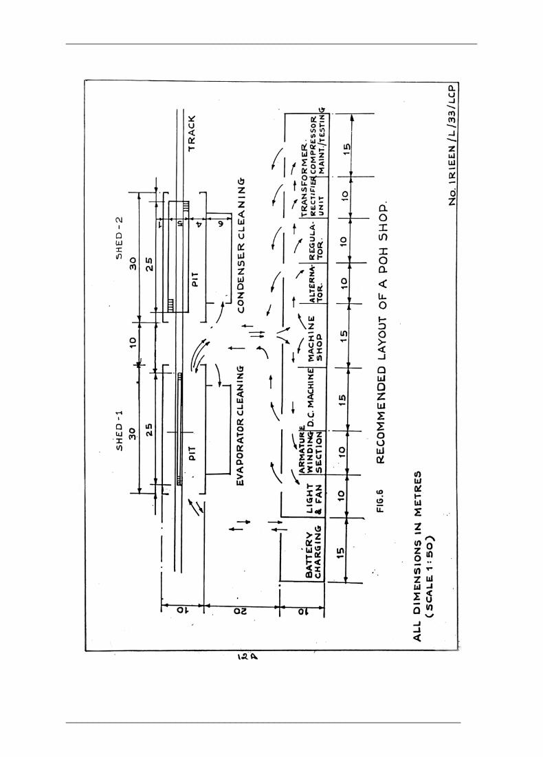
5.10.2 Recommended standard facilities for POH of AC coaches Fig shows a recommended layout of a POH Shop with an out-turn of 5 coaches per month. The layout envisages the following flow of work. • The layout incorporates a receiving shed with a pit of 1.35 M width, 1.3M depth
and 30 M long to facilitate unloading/loading of equipment. Track and pit centre line are located 1 M off from the shed centre line.
• The equipment unloaded from the coach may be moved to the respective sections of the shop by means of mechanised transport facilities.
• After completion of overhaul work, equipments may be loaded on the coach kept in the receiving line and then the coach shall be brought to the shed having wider line with a pit of 5 M width for final testing and detailed examination of underframe equipment.
________________________________________________________________________
___________________________________________________________________________
________________________________________________________________________

___________________________________________________________________________
5.10.3 Standard facilities for POI1 of AC coaches Requirements for the pit • For loading and unloading facilities, the pit width shall be 1.35 m (0.50 in
M.G.), length 30m and depth 3m with steps on both side. • For detailed exam /testing of underframe equipments, a pit having a width of 5m
shall be provided. • The walls of the pit shall be watertight. The pit floor shall have slope of 1 in
300 towards one end with sump • Suitable pump shall be provided for pumping out water from the pit. • Water tight fittings shall be provided in the sides of the pit at intervals of 6m. • 24 V D C two pin sockets 3 Nos in each side of the pit for hand lamps. • The wider pit shall be provided with 2 D.C. motor drives of capacity 25 KW each for
testing of Alternators.
5.10.4 Final testing of A/C coach after POH • Visual inspection of coach for proper fitment of equipments. • Ensure the refrigerant pipes are properly clamped. • Suction pipe for proper lagging. • Ensure all the modifications are complied. • Check safety chain and tension rod of B.L. Alternators for proper fitness. • Underframe cables leading to Alt. are properly cleared. • Check earth leakage by two lamp method. • Check refrigeration system for any leakage before gas charging, a. Vacuum test ( for 12 hrs.) b. Pressure test ( by charging Freon 12 or CO2 gas). • Vacuum test for 15 minutes for dehydration of refrigeration system. • Check control panel and ensure that proper fuses are provided. • Check contactors, relay and switches for correct sequential operation. • Ensure that time delay in operation of contactor No.12, 13, 13A is 2.5 sec. • Check heaters for correct operation. (Remove short between 1H 3 - 1H 4) • Check hooter for proper operation. • Start the plant and check condenser motor, compressor motor, blower motor for
any abnormality, • Check leakage of air from doors • Check oil level in compressor, the level should be when operating - 1/2 bull's eye. • Check for proper working of capacity control solenoid valve. • Run the plant for 4 hrs. An equivalent heat load (Convector heater) should be kept
for performance test of plain • If new expansion valve is provided during POH, it be set. • Ensure that batteries are in fully charged condition.
________________________________________________________________________
___________________________________________________________________________
• Take coach on trial run. Alternately test the alternator, regulator and AC plants for proper working with the help of variable speed drives in the shops itself.
• Ensure that both the alternators are sharing load equally during run. If not set both the alternator panels.
5.10.5 General checks • Suction pressure gauge reading should be 2.6- 2.8 Kg/Cm2. • Delivery pressure gauge reading should be 10 - 12 Kg/Cm2 . • Oil pressure should be minimum 3 Kg/Cm2 above suction pressure. • Feel temperature - Suction should be cold and sweaty. Delivery should be very
hot and liquid line should be warm.
5.10.6 Problems in AC coaches • Gas leakage in pipeline from joints in the control equipment. • Premature failure of shaft seal of compressor. • High heat in condenser leading to leakage of refrigerant. • Difficulty in cleaning of condenser. • Vee belt failure. • Compressor motor failure. • Condenser motor failure. • Dehydrator defective. • PCB defective in regulator.
5.10.7 Service trouble 1. HP cut out operates due to - • Malfunctioning of the cutout • Condenser fan motor failure. • Condenser fins and tubes dirty • Any stop valve is closed or partly closed. • Freon gas over charged. • Air in the system.
2. LP cut out operates due to - • Malfunctioning of LP cut out. • Gas leakage or under charge • Compressor motor running at less speed. • Internal valves of compressor not operating efficiently.
3. Insufficient cooling may be due to - • Thermostat not operating properly. • System under charged with freon. • Compressor motor running slow.
________________________________________________________________________

___________________________________________________________________________
• Choke in the system. • Any of the stop valve closed • Expansion valve choked or not opening sufficiently. • Condenser fins choked • Evaporator fins choked. • Air filters for return air choked. • Capacity control not working properly.
4. Excessive cooling may be due to - • Thermostat not operating. • Compressor motor failing to stop. 5.10.7 Service trouble 1. HP cut out operates due to - • Malfunctioning of the cutout • Condenser fan motor failure. • Condenser fins and tubes dirty • Any stop valve is closed or partly closed. • Freon gas over charged. • Air in the system.
2. LP cut out operates due to - • Malfunctioning of LP cut out. • Gas leakage or under charge • Compressor motor running at less speed. • Internal valves of compressor not operating efficiently.
3. Insufficient cooling may be due to - • Thermostat not operating properly. • System under charged with freon. • Compressor motor running slow. • Choke in the system. • Any of the stop valve closed • Expansion valve choked or not opening sufficiently. • Condenser fins choked • Evaporator fins choked. • Air filters for return air choked. • Capacity control not working properly.
4. Excessive cooling may be due to - • Thermostat not operating. • Compressor motor failing to stop.
________________________________________________________________________
___________________________________________________________________________
6. ROOF MOUNTED AIR-CONDITIONING
PACKAGE UNITS FOR RAILWAY COACHES
6. BRIEF DESCRIPTION The roof-mounted AC equipment for AC coaches of Indian Railways would provide more comfortable journey and also help attach more coaches in the superfast trains like Rajdhani Expresses. These roof-mounted AC units of new design are more efficient and lightweight and are manufactured indigenously. Two high capacity packaged air-conditioning units of minimum of 7.0 TR of cooling in 45°C ambient i.e. 14.0 TR for one coach, will replace the present underframe open type AC system of capacity 5.2 TR each (Total 10.4 TR) for each coach. Two packaged units are used in one coach each mounted above the toilets on both ends supplying conditioned air into a tapered duct to serve the coach end to end. The units (two in each coach) are fitted with 4 compressors but operate under normal with 3 compressors and the 4th one acts as standby and works only during peak days of the summer. Compressors are started in sequence with time delay to reduce the peak demand of electricity during start ups. These units are thus more energy efficient and are more reliable than the existing open units and would be better in operation. The high capacity AC units of roof mounted type is a fore runner to futuristic super fast trains. This units can work on E.O.G. systems in addition to S.G. systems . The roof mounted unit needs approximately 11.5 KW, 20 ampere at normal condition. Modular type AC units for rail coaches is a major breakthrough in rail-coach technology. A modular type roof-mounted packaged AC unit for rail coaches, the first of its kind brings India abreast with the latest in the state of the art of air-conditioning technology prevalent the World over. The units are extremely energy efficient and reliable. They use two hermetically sealed compressors of half capacity in each packaged unit. These compressors are specially developed for rolling stock application under varying dynamic conditions after rigorous testing and trials before being used in the AC units. 6.1 PRESENT SYSTEM The AC coaches running on Indian Railways can be broadly divided into two categories. • Self generating (S.G.) coaches. • End-On-Generation (EOG) coaches.
6.1.1 Self-Generating Coaches Power supply demand for AC equipments is met from axle driven transom-mounted brushless alternator which is rated for 110 V DC supply. At low speeds and during halts the
________________________________________________________________________
___________________________________________________________________________
power requirement is met from 110 V lead acid battery housed in battery boxes mounted on the underframe of the coach.
6.1.2 End-On-Generation Coaches AC coaches draw power from the diesel-generating sets carried in coaches put in the front and rear of the rake, functioning at 415/750 V, 3 phase, 50 Hz AC supply. The power is distributed to entire rake and thus to each coach through two sets of 3 phase 415/750 V feeders. Each coach is provided with control, distribution and feeder changeover arrangement on 415/750 V control panel. The AC equipments operate at 415 V, 3 phase, 50 Hz AC supply. The airconditioning system in both types (SG or EOG) of Indian Railways stipulates use of open type compressor, condenser, liquid receiver with dehydrator separately mounted on the underframe of the coach. The evaporator comprising cooling coils, heater elements and blower fans with motor is mounted between coach roof and false ceiling. The conditioned air is blown through the central duct and distributed inside the coach through adjustable grills diffusers.
6.1.3 Draw-backs of conventional AC system The existing system using open type compressor, poses problems such as refrigerant leakage from pipes and their joints heavy weight, large space occupation, more maintenance problems, consuming more power and thus less energy efficient.
6.2 SALIENT FEATURES OF ROOF-MOUNTED AC PACKAGE UNITS • Light in weight, saves fuel for hauling. Total weight of both units is 900 Kg as
compared to 2700 Kg for conventional AC unit. Saves in fuel consumption. In the Rajdhani express e.g. the total weight reduction in 20 coaches (1.8 x 20 = 36 MT) equals the weight of one coach. Therefore, one additional coach can be hauled.
• Keeping in view the low price and light weight, the unit pays for itself in one year operation.
• Low cost of installation at the coach building factory since the system is factory made, assembled, gas charged and tested for performance prior to delivery.
• The installation requires simply to lower the unit in the false ceiling above the toilets on both ends of the coach and connection of wiring, drain pipe and flexible duct.
• In case of failure, replacement of the unit with new unit can be done in less than two hours by simply lifting the defective unit by a crane and lowering the new one in place.
• The A.C unit remains outside the partition wall and therefore, no chance of water leakage on passengers
• Fresh air is taken from the roof through condenser area which gives a relatively clean air free of the smells of toilets which are common in conventional A.C. coaches.
________________________________________________________________________
___________________________________________________________________________
• Hermetically sealed system with no fittings or openings, thus it presents little potential of gas leakages and break-downs.
• The unit is almost maintenance free since it uses 3ph AC motors which have no commutators or brushes to wear out.
• Uses more environment friendly refrigerant R-22 and very small quantity less than 3 Kg.
• Mounted on the roof, thus dirt or dust collection in condensers is negligible and therefore, requires practically no maintenance or water spraying on condenser coils.
• No chance of damage due to flash floods during the monsoons. • No chance of damage due to cattle run. • Energy efficient - uses less electricity, saves fuel for generation. • Humidity control in monsoons possible through use of micro processor - based
control system. It will also provide optimum use of all equipments and even wear to compressors through rotation of operation.
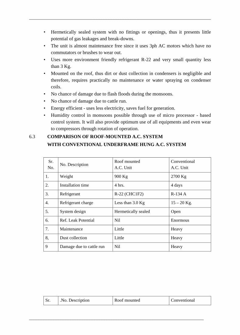
6.3 COMPARISON OF ROOF-MOUNTED A.C. SYSTEM WITH CONVENTIONAL UNDERFRAME HUNG A.C. SYSTEM
Sr. No.
No. Description Roof mounted A.C. Unit
Conventional A.C. Unit
1. Weight 900 Kg 2700 Kg
2. Installation time 4 hrs. 4 days
3. Refrigerant R-22 (CHC1F2) R-134 A
4. Refrigerant charge Less than 3.0 Kg 15 – 20 Kg.
5. System design Hermetically sealed Open
6. Ref. Leak Potential Nil Enormous
7. Maintenance Little Heavy
8, Dust collection Little Heavy
9 Damage due to cattle run Nil Heavy
Sr. .No. Description Roof mounted i
Conventional i
________________________________________________________________________

___________________________________________________________________________
No. A.C. Unit A.C. Unit
10. Damage due to flash floods
Nil Heavy
11. Performance Excellent
Deteriorates quickly due to dust collection under coach
12. Technology Latest Old and obsolete
13. Water drop on passengers Nil Some times
14. Fresh air From roof (Does not take toilet smell)
From sides (Takes toilet smell)
15. Capacity control 25% to 100% (4 compressors)
50% to 100% (2 compressors)
16. Down time for repair 4 Hrs-(Replace unit) Very long (Requires repairs to be made on coach itself)
6.4. PERFORMANCE OF ROOF MOUNTED AC PACKAGE UNITS Major problems/short comings experienced by railways with roof mounted AC package units are, • Gas leakage. • Water ingress into corridor. • Tripping of packages through safety cut-outs. • Failure of AC control panel
6.4.1 Gas leakage This problem was more acute in packages of one particular make. Analysis of problem indicated that this was due to, • Packages were not subjected to the vibration test. • Inadequate securing of refrigerant piping. • Non-securing of compressor top resulting into excessive vibration in discharge
pipe. • Defective packless vibration eliminator (particular lot). • Other manufacturing shortcomings like longer length of charging line,
unsatisfactory brazing etc. The concerned firm in consultation with RDSO and IIT, Delhi, have carried out
________________________________________________________________________
___________________________________________________________________________
following modifications. • Securing refrigerant piping properly specially at the places where vibration levels
were found to be on higher side by IIT, Delhi, • Securing the compressor at the top and using solid mounting pads. • To replace packless vibration eliminators with U loop. • To improve the general workmanship and conducting tests more rigidly. Packages with these modifications have been successfully tested for vibrations. The other make has also been tested for vibration,
6.4.2 Water ingress into corridor This problem can be classified into two categories; • Problems related to rain water • Problem related to condensate water. Major factors contributing to first problem were, • Inadequate/ineffective drainage area • Interfacing between trough and package not water tight. • Package not of standard design and not water tight.
Inadequate/ineffective drainage area This is considered to be the major culprit. It is felt that if it is corrected there will be considerable improvement. Drainage area has now been increased to about three times of the earlier and also made effective by taking if vertically downward from the bottom of the trough.
Interfacing between trough and package not water tight In earlier design, packing provided between package and trough was getting dislodged due to sustained vibrations. Now the arrangement has been modified to have single gasket under point pressure mounting with skirting all around the opening.
Package not of standard design and not water tight Water was found to be entering into the corridor through evaporator area and other structural members of the package due to not standard design and evaporator section not being water tight. This stands corrected now.
Problem related to condensate water This problem can be further divided into two categories: a. Condensate water dropping into corridor. b. Condensate water carried over by blower and thrown into duct. Problem 'a' has been observed in both packages while problem ‘b’ is confined to only one make of package units. Causes of the problem as identified are,
________________________________________________________________________
___________________________________________________________________________
• Condensate water collected into drip tray not getting drained off effectively due to non provision/removal of air trap (U-trap) at the outlet of condensate drain or due to improper slope of the external drainage connections This stands corrected now.
• Defective drip tray design in respect of inadequate depth and covering at the top. • Clogging of filters - This needs to be looked into by Railways. In the latest packages condensate drain has been taken towards condenser area and provision of U-trap is in the scope of package manufacturer. This is expected to eliminate the problem due to negative pressure of blower over drip tray getting partly neutralized by condenser and also the intact provision of U-trap. Design of drip tray has also been modified to provide maximum possible depth. It is felt that if the filters are periodically cleaned problem will not be experienced. For the existing coaches modifications have been evolved and demonstrated on three ACCNs with full trough. Modification in respect of coaches with half trough are under validation. Modifications require two inputs, a. Modification in trough. b. Modification of old packages to make them conforming to latest design. While input 'a' is to be arranged by railways on their own, for input 'b' RCF has entered into contracts with package manufacturers for which even the cost will be born by RCF. It has also been jointly decided by RDSO & RCF to try out flat roof mounting arrangement of AC package on few coaches for which drawings are to be given by RDSO.
6.4.3 Tripping of packages through safety cut-outs This problem was experienced during the peak of summer. To overcome the problem, RDSO's relevant specification has been revised specifying the satisfactory functioning of the package at an ambient of 57°C.
6.4.4 Failure of AC control panel Initially AC control panels supplied by different manufacturers were of different designs and lay-outs which were causing lot of problems. Subsequently, RCF standardized the lay-out and design of control panel to have 100% interchangeably among different makes. The procurement of panels was offloaded to industry as package manufacturer did not respond promptly enough and also due to price implications. However, in these panels, problem of coordination and poor quality of particular make of switchgear items were reported by railways. Railways have been advised to replace this particular make of items by Siemens make which can be made available by RCF. Accordingly a decision has been taken to procure the control panel from package manufacturers alongwith AC packages. Earlier, there were two types of control panels one with 110V AC control supply and other with 110V DC supply. Specification of control panel has been revised by RDSO. Now there will be only one type of control panel (with 110V AC control supply) for both SG and EOG type coaches.
________________________________________________________________________

___________________________________________________________________________
7. A/C 3TIER SLEEPER COACH FITTED WITH ROOF MOUNTED A/C PACKAGE UNIT WITH
E.O.G. SYSTEM OF POWER SUPPLY
7.0 TECHNICAL DETAILS The A/C unit shall be capable of maintaining inside conditions as under :
DBT WBT RH (ºC) (ºC) (ºC) Outside (Dry Summer) 45 25 – Outside (Wet Summer) 40 28 – Inside (Dry & Wet Summer) 24 – 40
Each coach shall be provided with two roof mounted A/C units each with a minimum cooling capacity 20,000 K.Cal/hr (6.6TR). The roof mounted A/C package unit shall generally confirm to RDSO specn. No.ELPS/SPEC/AC/01.
Refrigerant Compressor Hermetic or semi-hermetic refrigerant compressors working with Freon 22 (monochloro difluoro methane) are provided in the A/C package unit. The compressor motor is rated for 415V, 3Ph, 50 HZ, AC Power Supply. Make & Model – Kirloskar. Hermetically Sealed. Power Consumption – 5. 25KW +/-20% depending upon Ambient temp. Current (Amps.) – 8.25 +/- 25% at 415V, 3Ph,50HZ,AC Power Factor
- 0.8 C.F.M. – 12.033 Volume – 117.65 CC/Rev. Refrigerant Condenser
Refrigerant Condenser Condenser Coil – Fin-on-Tube Face Area – O.67 M2 x 2 Material of tube – Copper Tube O.D. – 9.62 mm Fin material – Aluminium Fin Thickness – 0 19 mm No. of Fins/cm – 4.3 +/- 1
________________________________________________________________________
___________________________________________________________________________
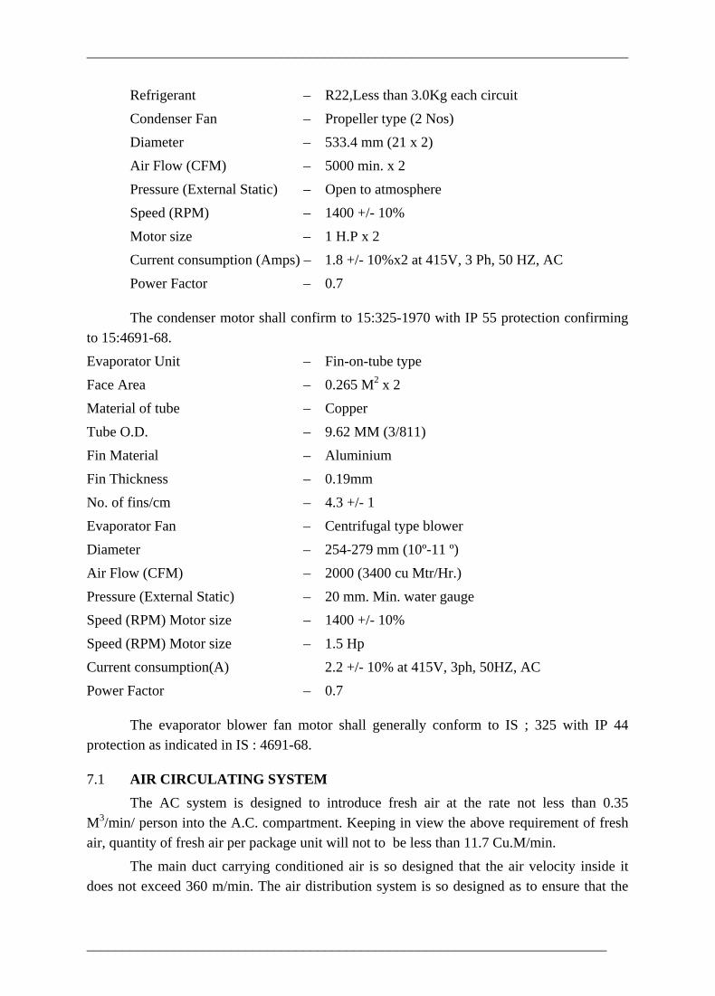
Refrigerant – R22,Less than 3.0Kg each circuit Condenser Fan – Propeller type (2 Nos) Diameter – 533.4 mm (21 x 2) Air Flow (CFM) – 5000 min. x 2 Pressure (External Static) – Open to atmosphere Speed (RPM) – 1400 +/- 10% Motor size – 1 H.P x 2 Current consumption (Amps) – 1.8 +/- 10%x2 at 415V, 3 Ph, 50 HZ, AC Power Factor – 0.7
The condenser motor shall confirm to 15:325-1970 with IP 55 protection confirming to 15:4691-68. Evaporator Unit – Fin-on-tube type Face Area – 0.265 M2 x 2 Material of tube – Copper Tube O.D. – 9.62 MM (3/811) Fin Material – Aluminium Fin Thickness – 0.19mm No. of fins/cm – 4.3 +/- 1 Evaporator Fan – Centrifugal type blower Diameter – 254-279 mm (10º-11 º) Air Flow (CFM) – 2000 (3400 cu Mtr/Hr.) Pressure (External Static) – 20 mm. Min. water gauge Speed (RPM) Motor size – 1400 +/- 10% Speed (RPM) Motor size – 1.5 Hp Current consumption(A) 2.2 +/- 10% at 415V, 3ph, 50HZ, AC Power Factor – 0.7
The evaporator blower fan motor shall generally conform to IS ; 325 with IP 44 protection as indicated in IS : 4691-68.
7.1 AIR CIRCULATING SYSTEM The AC system is designed to introduce fresh air at the rate not less than 0.35 M3/min/ person into the A.C. compartment. Keeping in view the above requirement of fresh air, quantity of fresh air per package unit will not to be less than 11.7 Cu.M/min. The main duct carrying conditioned air is so designed that the air velocity inside it does not exceed 360 m/min. The air distribution system is so designed as to ensure that the
________________________________________________________________________

___________________________________________________________________________
max. air velocity at 150 mm below duct/diffuser is 10m/min. and at 1.2 m from floor level is 15m/min Four types of diffusers are used in the conditioned compartment for distribution of cool .air. Type 'A' larger diffuser and type B smaller diffuser are provided on the main duct. Type 'C' and type 'D' diffusers are provided on the branch ducts for transverse and longitudinal berths respectively. Branch ducts of size not less than 50 mm is brought down near the window from the main duct on both sides. The diffusers on both the branch ducts are mounted in the inclined position to direct cool air towards lower berths. The branch diffuser on the longitudinal berth's side is provided with adjustable vanes to control quantity of cool air. The diffuser on branch ducts for transverse berths is made in two parts, each part directing cool air towards the lower most berths of the bay. These are also provided with variable vanes.
7.2 POWER SUPPLY ARRANGEMENT The electrical load in the coach is fed through two sets of 415V, 3Ph, AC, 4 wire feeders run along the rake and coupled to the coach with the help of inter vehicular couplers. Each coach on the rake is provided with the control, distribution and feeder changeover arrangement on 415V control panel. The 415V, 3Ph, supply is transformed with the help of a 415/190V, delta/star, 3Ph, transformer of 3KVA capacity for supplying the light and fan loads. A separate control panel/junction box is provided inside the coach for control and distribution of 3Ph, 4 wire, 190V (110V, 1Ph) system for lights and fans. Two sets of latched and electrically interlocked coupling of cable and plug socket and dummy socket one at each end panel of the coach is provided for transmitting the feed to the adjacent coaches on either side. Water raising apparatus is fed at 240V, 1Ph, 50 HZ, AC. One emergency lighting battery 24V, 90AH. is provided on the under frame to feed emergency lights in case of failure of power supply. One battery charging transformer rectifier unit is provided on the under frame to charge emergency lighting battery.
________________________________________________________________________
___________________________________________________________________________
8. SALIENT FEATURES OF AIRCONDITIONING IN LHB VARIANTS OF AC COACHES
8.0 LHB coaches are coaches of special design being mow manufactured by RCF Kapurthala on the basis of design and technological transfer from M/S ALSTHOM LHB. The air-conditioning of these coaches incorporate micro-processor controlled air-conditioning system with a number of advanced technical features for comfort air-conditioning. The important features of air-conditioning are as follows .The various RMPUS used in LHB coaches are
1) Sidwal make,
2) Fedder lloyd make
3) Amit engineering make
4) Lloyd Electric makes.
The AC system is described below based on Sidwal make RMPU ac coach package unit and their systems
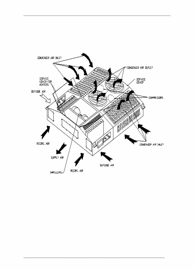
8.1 ROOF MOUNTED AC PACKAGE UNIT (SIDWAL MAKE) The AC system for all type of coaches and generator cars of Indian railways provides the following functions in all rooms used by either the train staff of passengers, such as the passenger compartment, staff compartment, WC, kitchen and rooms accommodating the switchgear. • Ventilation • Air heater • Air cooling • Air dehumidification • Air filtering 8.1.1 CONSTRUCTION
The coaches are provided with two Nos compact air-conditioning units each and the generator cars with one air- conditioning unit each. However the units used in the different car type are identical.
________________________________________________________________________
___________________________________________________________________________
________________________________________________________________________

___________________________________________________________________________
Diagram of Control panel in LHB coaches
8.1.2 The AC system for the Passenger and Generator cars consists of the following
assemblies:
• Compact air conditioning unit
• Duct system
• Exhaust air system
- Exhaust air unit
- WC/WC exhaust fan
- WC/switch cabinet exhaust fan
• Circulating air duct system
• Fresh air screen
• Open/closed-loop control devices
• Sensors
8.1.3 COMPACT AIR CONDITIONING UNIT
________________________________________________________________________
___________________________________________________________________________
The compact air conditioner unit has been designed for the air conditioning of 2 tier, 3 tier & chair car for Indian Railways. The outside air (fresh air) is sucked in via the two fresh air screens and their air filters on the carriage side wall. It is mixed in the unit with the outside air/ recirculating air ratio can be set by means of air dampers, the positions of which are controlled by the computer of the air conditioning system. The dimensions of the air conditioning units have been designed to match the car profile. Being installed in a recessed trough, it does not protrude from the car profile. The compact air conditioning unit has two separate cooling circuits consisting of the following components: • two hermetic refrigeration compressors with oil heaters • two condenser with Cu pipes and Al. Fins • two axial fans for cooling the condensers • two evaporators • two twin-sucking radial fans for the supply air (driven by the motor) • three maintenance covers • two air inlets for circulating air • one air outlet for supply air • control and safety devices • pipelines/fittings • two mixed air filters
8.1.4 Operating modes 8.1.4.1 Preheating and cooling operation The outside air dampers are closed to facilitate rapid heating up or cooling down of the carriage
8.1.4.2 Normal operation In the normal operating mode, the dampers are set to ensure the envisaged fresh air volume of 21 m3/h per person. 8.1.4.3 Emergency operation Should the AC system fail due to a failure of the power supply, the adjusting dampers of the circulating air duct close so that the system is operated exclusively with outside air.
________________________________________________________________________

___________________________________________________________________________
The supply air fan of the compact air conditioning unit sucks the air from the mixing chamber across the two mixed air filters and evaporators and forces it via the electric heater into the supply air duct of the carriage. The condenser fans concurrently suck fresh via ventilation slots provided on both sides to cool the compressor-condenser section. The supply air is first carried via silencers into the thermally insulated supply air duct, which is diagonally split in the longitudinal direction. The air is then supplied via openings in he bottom into a compensating chamber and from there via the perforated ceiling into the passenger compartment. 8.5 Controller All controlling and regulating functions are performed by the digital controller. It is built in an EMC proof standard plug-in rack using so-called 19” technology that is designed for plug-in cards of Eurocard form factor. This rack contains all required electronic cards needed for the unit. This combination of cards and wiring between the cards have been specifically designed that have been used for many years in high quantities in various railway HVAC equipment. All signals are passed into this device via 2 front-side multiple cable connectors on position X1 and X2, Where as 110V supply is located on a separate front side connector on card A1of controller. 8.5.1Software / operating modes The control of air-conditioning system is divided into the following operating modes: - Test mode - Emergency mode - Control mode 8.5.2 Test mode This mode only supports a test run that uses the dedicated service program PRUEFWIN (in
case of Sidwal) and a PC. The PC is connected to a/c computer via the serial port. There is one, command “H”, for “test mode”. The software will switch off all outputs and enter testing mode for duration of 2 hours. During this time any output may be manually. Set or reset with the help of ‘Z’ command, To escape prematurely from testing mode the HVCV controller must be reset by powering off and on the 110V supply. Then the user can test the individual operating functions of the system.
8.5.3 Emergency mode
________________________________________________________________________
___________________________________________________________________________
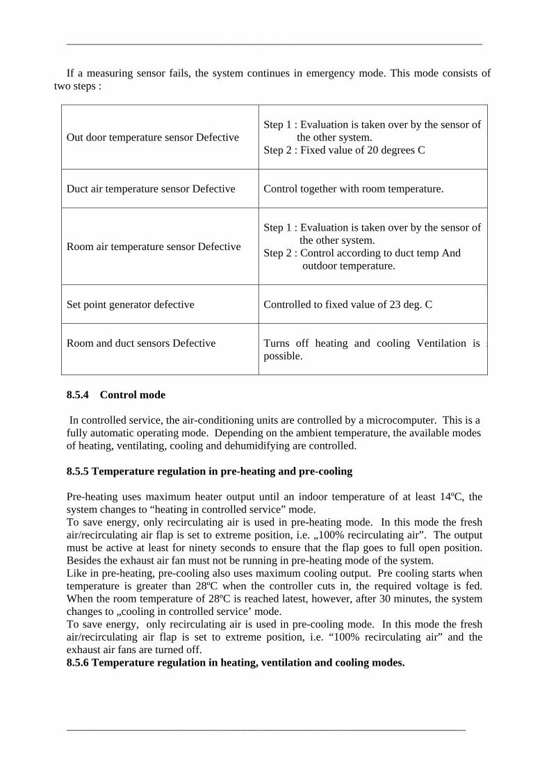
If a measuring sensor fails, the system continues in emergency mode. This mode consists of two steps :
Out door temperature sensor Defective
Step 1 : Evaluation is taken over by the sensor of the other system. Step 2 : Fixed value of 20 degrees C
Duct air temperature sensor Defective
Control together with room temperature.
Room air temperature sensor Defective
Step 1 : Evaluation is taken over by the sensor of the other system. Step 2 : Control according to duct temp And outdoor temperature.
Set point generator defective
Controlled to fixed value of 23 deg. C
Room and duct sensors Defective
Turns off heating and cooling Ventilation is spossible.
8.5.4 Control mode
In controlled service, the air-conditioning units are controlled by a microcomputer. This is a fully automatic operating mode. Depending on the ambient temperature, the available modes of heating, ventilating, cooling and dehumidifying are controlled.
8.5.5 Temperature regulation in pre-heating and pre-cooling Pre-heating uses maximum heater output until an indoor temperature of at least 14ºC, the system changes to “heating in controlled service” mode. To save energy, only recirculating air is used in pre-heating mode. In this mode the fresh air/recirculating air flap is set to extreme position, i.e. „100% recirculating air”. The output must be active at least for ninety seconds to ensure that the flap goes to full open position. Besides the exhaust air fan must not be running in pre-heating mode of the system. Like in pre-heating, pre-cooling also uses maximum cooling output. Pre cooling starts when temperature is greater than 28ºC when the controller cuts in, the required voltage is fed. When the room temperature of 28ºC is reached latest, however, after 30 minutes, the system changes to „cooling in controlled service’ mode. To save energy, only recirculating air is used in pre-cooling mode. In this mode the fresh air/recirculating air flap is set to extreme position, i.e. “100% recirculating air” and the exhaust air fans are turned off. 8.5.6 Temperature regulation in heating, ventilation and cooling modes.
________________________________________________________________________

___________________________________________________________________________
The room temperature is exclusively controlled by the microcomputer.
8.5.7 Room set point temperature in cooling mode / Heating Mode
Switch S1U1R1. Set point generator has 7 point temp. selector switch
Summer Winter
1.
20.0°C 17.0°C
2.
20.5 °C 17.7°C
3.
21.3 °C 18.3°C
4.
22.3 °C 19.0°C
5.
23.2°C 19.7°C
6.
24.0 °C 20.0°C
7.
25.0 °C 21.0°C
8.5.8 Cooling circuit control
If a cooling power request is received, a safety check is made before the compressor is turned on. The following information is available and should be observed:
• Thermal monitoring of the condenser fan • Suction pressure message • High pressure message
8.6 Dehumidification The dehumidification function is available at cooling mode step 2. It is used if the relative humidity of the room air rises to 60%. This condition is monitoring by the moisture sensor in input C7S3. If the relative humidity is less than 60%, a simulated temperature of below 60°C is measured (Appro. 10 kΩ ). When the sensor switches, this resistance is reduced via a measuring bridge so as to enable measurement over (appr.1 kΩ ).During dehumidification, the room temperature is controlled by the extra heater. Extra heating is maintained until • The cooling power of the second step becomes insufficient to maintain the room
temperature even at maximum cooling output, or
________________________________________________________________________
___________________________________________________________________________
• The moisture sensor relative humidity of less than 60%. In dehumidification service, a max 50% of the cooling output is allowed to ensure that the combined power consumption of the refrigerating and heating units does not exceed the maximum cooling output. This is ensured by limiting the dehumidification function to cooling step 2. The higher power consumption that would be needed if 2 compressors were turned on simultaneously is avoided by delaying the start of the second compressor by 5 seconds.
________________________________________________________________________
___________________________________________________________________________
9. RAKE LINKS
9.0 INTRODUCTION The basic requirements for rail transportation system are: • Railway track, • Signalling and telecommunications, • Rolling stock which contains locomotives, coaches and wagons, • Maintenance and operating personnel of these assets. Railway track and signals are fixed assets and these are must for running of trains irrespective of the number of trains run, whereas the rolling stock and crew requirement are based on quantum of traffic to be handled. As such, careful planning is required in acquisition and utilisation of the coaches, especially the A.C. coaches, since they are costly assets. Minimum turn-round time will increase the number of trips which, in turn, yield greater dividends with minimum number of coaches.
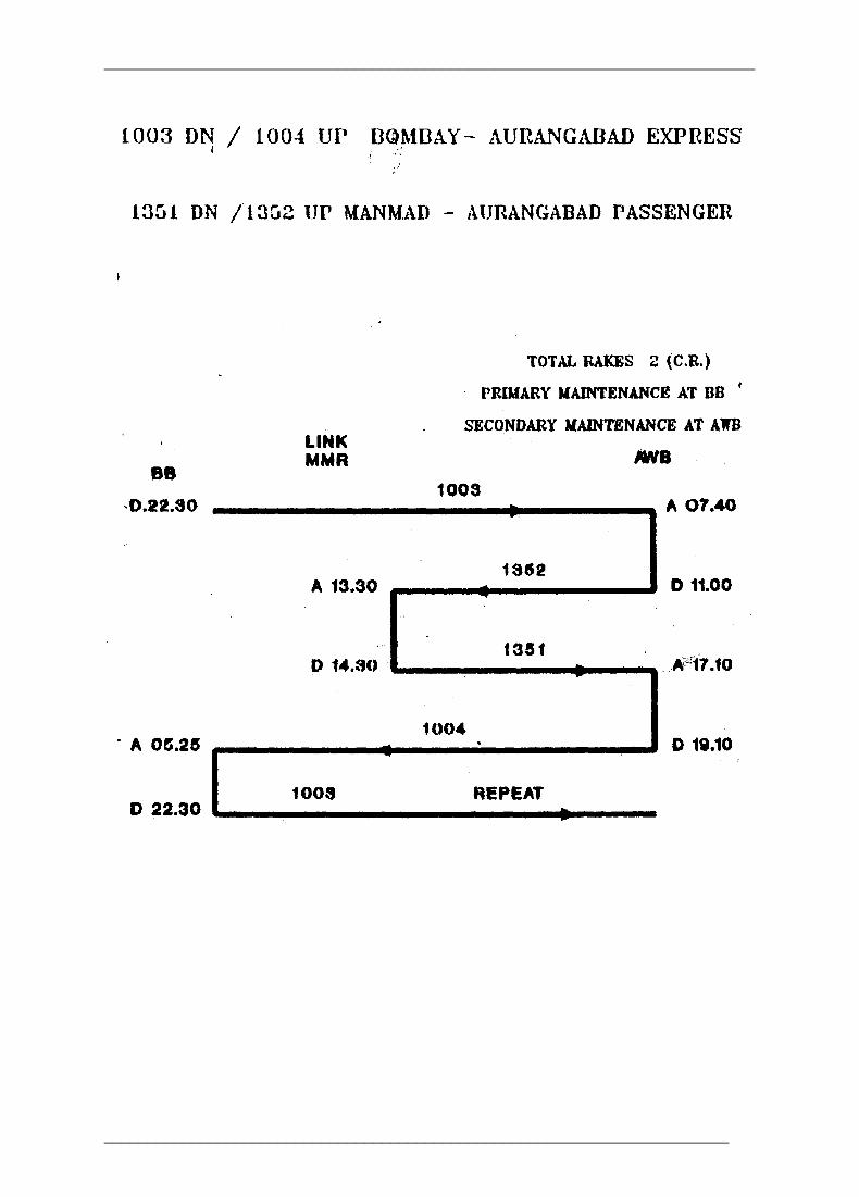
9.1 OBJECT The object of rake links is to ensure optimum utilisation of coaches with minimum lie-over period at destination as well as availability of coach for trip and schedule inspection on due date so that the same is maintained in good fettle for reliable service. Rake links indicate the sequence in which coaches have to operate. Rake links give all the information about the movement of coaches at a glance and can be used as a ready reckoner by operating staff. In order to achieve maximum utilisation of the rakes, rake-links are prepared in such a manner that the coaches are kept on run for the maximum number of hours each day with the minimum detention at the terminal stations. Ideal rake-link is one in which lie-over of coaches at destination is minimum, utilisation (km earning per coach per day) is maximum.
9.2 POINTS TO BE KEPT IN MIND WHILE PREPARING RAKE-LINKS. • Coaches shall be made available for carrying out trip inspection at terminal stations.
This shall be indicated in the rake-link itself. Coaches are to be made available to the owning depots for carrying out maintenance schedules such as monthly, three monthly. POH etc.
________________________________________________________________________
___________________________________________________________________________
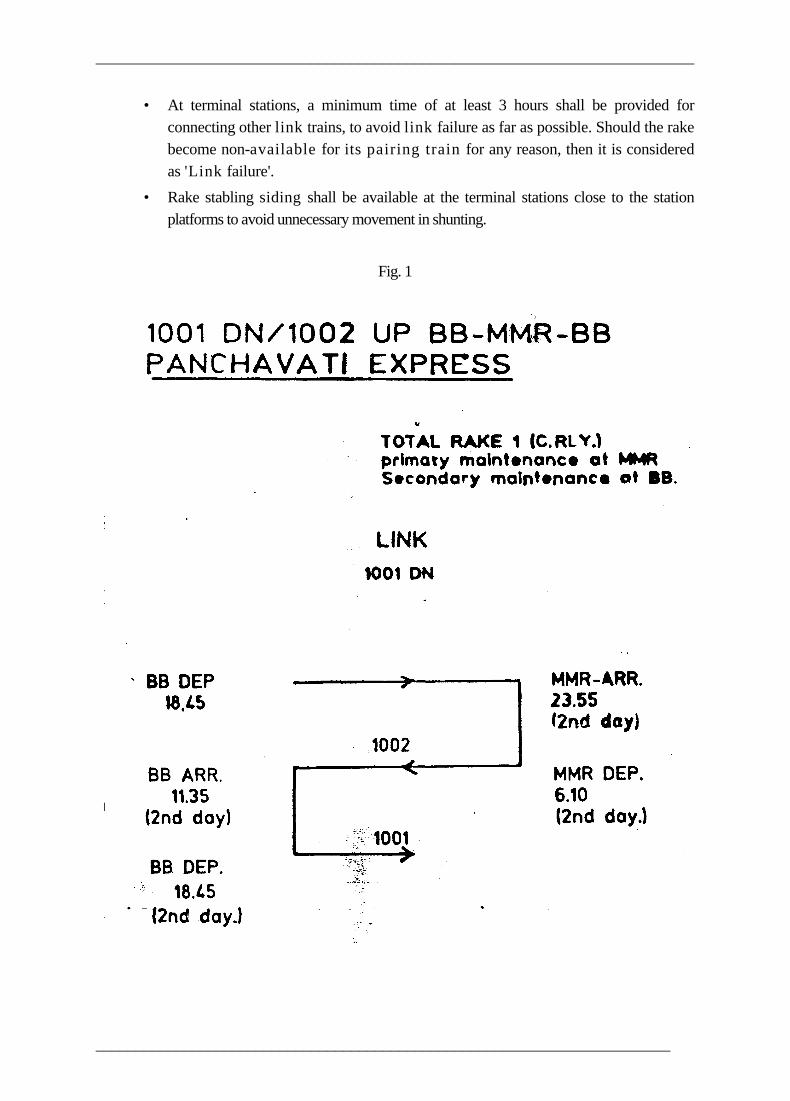
• At terminal stations, a minimum time of at least 3 hours shall be provided for connecting other link trains, to avoid link failure as far as possible. Should the rake become non-available for its pairing train for any reason, then it is considered as 'Link failure'.
• Rake stabling siding shall be available at the terminal stations close to the station platforms to avoid unnecessary movement in shunting.
Fig. 1
________________________________________________________________________
___________________________________________________________________________
________________________________________________________________________
___________________________________________________________________________
10. AIR CONDITIONING OF OTHER
INSTALLATIONS
10.0 WINDOW TYPE UNITS Air conditioners of the window type, are completely self-contained units, with the compressor, condenser, evaporator, refrigerant piping and air filter, all assembled in a very compact assembly. The window units are usually of 1/2 to 2 tons capacity and fitted with 230 V motor upto 3 HP. Modern tendency is to employ sealed type motor-compressor units with the refrigerant piping system sealed-in with brazed joints, so that the leakage of gas is virtually eliminated and the unit may serve for long periods with hardly any attention. In these units expansion valve and liquid receiver are not provided. The refrigerant is controlled with the capillary system. The unit is so designed that it can be mounted on the window with small bracket from outside. Window units are particularly adopted when only few rooms are to be air-conditioned and they are widely separated. Window type unit has following advantages; • Maintenance cost is less and very little, since the system is sealed. • Ducts are not required. • Occupy less space. • Shaft seal is eliminated. • No alignment problem. • Better-cooling of compressor motor from the suction gas. The greatest disadvantage of the system is that since every thing is sealed, no repair can be carried out in field. The unit has to be repaired in workshop after cutting the sealed housing. The first cost of installation becomes 50 to 100% costlier than central unit when a number of units are employed for air-conditioning a large area.
Periodic maintenance To enable the conditions of both of the atmosphere and unit to be healthy it is imperative to give a periodic maintenance to the unit. The period is to be fixed as per the experience gathered or as specified by the manufacturer. The following are the important aspects to be looked after during maintenance. • Give attention to condenser coil, cooling coil and fan. 'Dust off these either by
compressed air or brush it. CO2 may be used if available.
________________________________________________________________________
___________________________________________________________________________
• Hold the naked light in front to check the cleanliness in between. A hooked wire should be used to remove the foreign material Cooling coil need not be cleaned so frequently.
• Fresh air ducts should be cleaned and checked. • Check the compressor mounting springs if external mounting is done. Replace
them if necessary. Spring tend to loose its tension with age and this leads to noisy operation of the unit.
• Check the earthing connections. • If necessary oil the dampers. View the unit slope. • It should be 1/2 to 3/4" towards outside. • Check the air fillers.
10.1 PACKAGE UNIT These units are functionally similar to the window models but are very much bigger in size and therefore arranged for floor mounting. These are available in several capacities i.e. 4,6, 8 and 12 tons. These units contain all the elements for cooling, dehumidifying, ventilating and circulating air and is quiet in operation. In larger sizes, the condenser is often water cooled and the necessary pipe connections will have to be made The compressor unit may be of the hermetically sealed, semi-sealed or open type. The control panel is conveniently located and provided with a 3 position switch marked 'OFF’, 'Fan', and 'Cool', in addition to a knob for setting the temperature at which the thermostat is to function. The disadvantage, however, is that the cost of installation is much higher than that of a central plant specially if large area has to be air-conditioned.
10.2 CENTRAL PLANT A central plant with full ducting is best suited for air conditioning of large buildings, theatres, halls and un-partitioned offices. In the central plant system, the airconditioning plant, comprising two or more heavy compressor units including the ancillary equipment like condensers and evaporators are located at a central point usually at the ground floor or basement. The conditioned air is delivered through a ducting system to all parts of the building. A duplicate ducting system is required to lead back the return air from inside, back to the central plant, to be dehumidified, cooled and recharged with fresh ventilating air to be circulated once again. The ducts are usually bulky and cumbersome as they have to handle large quantities of air. To accommodate them and keep them out of sight is a problem which often poses structural difficulties. In a large hall, network of ducting would be required to distribute the air uniformly to all parts. Individual DAMPER VANES are necessary to control the amount of air admitted at each outlet, as also at points where smaller ducts branch out. A considerable amount of adjustment and experimentation would be required to maintain the temperature variation within 1 or 2O C over all parts.
________________________________________________________________________

___________________________________________________________________________
One advantage of this system is that the processing of air is centrally controlled and therefore a high standard of efficiency can be maintained. The compressor plant itself being large is sturdy and robust and could operate for long periods with little attention. Normally there should be at least two complete independent units, one a working set and the second a standby,
Fig 1.
SCHEMATIC DIAGRAM OF A.C. SYSTEM
________________________________________________________________________
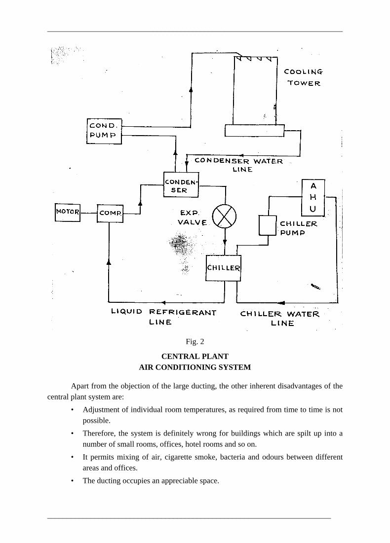
___________________________________________________________________________
Fig. 2
CENTRAL PLANT AIR CONDITIONING SYSTEM
Apart from the objection of the large ducting, the other inherent disadvantages of the central plant system are: • Adjustment of individual room temperatures, as required from time to time is not
possible. • Therefore, the system is definitely wrong for buildings which are spilt up into a
number of small rooms, offices, hotel rooms and so on. • It permits mixing of air, cigarette smoke, bacteria and odours between different
areas and offices. • The ducting occupies an appreciable space.
________________________________________________________________________
___________________________________________________________________________
10.3 DESERT COOLER The desert cooler works on the principle of evaporative cooling. A fan sucks outside air through a continuously wetted pad. The air in passing through the wetted pad gets cooled and humidified and this air is circulated into the room, where it picks up sensible heat and maintains fairly comfortable conditions as fresh air is continuously pumped into the room. The air from the room should be allowed to escape out through an opening at the farthest end of the room.
10.4 WATER COOLERS AND REFRIGERATORS 10.4.1 Refrigerator The majority of domestic refrigerators operate on the vapour compression system, the basic unit being a hermetically sealed electrically driven compressor unit which may be of the rotary pump type or reciprocating type. The unit is mounted at the base of the cabinet. The refrigerant commonly used is Freon22. The motor is generally of the high torque squirrel cage induction type using split phase design or employing capacitor start principle and operating on AC 230 volts 50 Hz supply. The usual expansion valve is done away with and replaced by one or more capillary The evaporator piping is fastened round and brazed to the freezer box. The condenser too is greatly simplified by laying the condenser tube to and fro over a single metal sheet and plate acts as a heat sink and dissipates the heat to air currents on the two sides of it. This type of construction eliminates the need for a condenser cooling fan. The top of the food storage space is reserved for the freezer unit for making ice cubes or storing foods for long periods at a low temperature. The rest of the cabinet interior gets cooled by convection currents of air set up by the freezer unit. The compressor unit starts and stops automatically under the control of an adjustable thermostat which in turn operates a relay.
10.4.2. Water coolers Water cooler is a machine working -on refrigeration system for cooling water for drinking purpose. The drinking water having temperature between 10OC to 13OC is preferred. As for the refrigeration system it is same which is utilized in airconditioning, refrigerators, etc. The water coolers can be classified into two main categories: • Instantaneous water coolers • Storage type water coolers It consists of a fabricated metal sheet work and the refrigeration equipments are installed inside. There is no storage tank for storing and cooling the water. The water is being cooled by the refrigerant no sooner the water flow starts. That is why, the name is given instantaneous water cooler. Here both evaporator coils and refrigerant coils welded together or one coil is passed inside the other coil (i.e. tube in tube arrangement) so that the maximum efficiency can be achieved. The evaporator unit is also insulated to avoid the flow of surrounding heat. The refrigerant takes away heat from water and changes to vapour. The
________________________________________________________________________
___________________________________________________________________________
compressors used are normally hermetically sealed. The condenser is air cooled and a separate motor is provided for cooling the condenser. The capacity of this type of water coolers is small and another disadvantage is that in case of electric supply failure cooling of water will not take place.
Storage type water cooler As the name employs, there is water storage tank depending upon the capacity of plant. The water is stored in stainless Steel tanks, G.I. tanks, or brass tanks. The evaporator coils are welded outside around the storage tank for heat exchange between the water in the tank and refrigerant passing through the evaporator coils. The condensing unit will continue to run so long the water temperature is not attained. The compressor used is sealed as well as open type. The refrigerant is being controlled normally with capillary in sealed units and. expansion valve in open type units. In some of storage water coolers the evaporator coils are directly kept in water as heat exchange will be good. But disadvantage is that the mineral salts of the water gets deposited over the evaporator coils and further heat exchange does not take place. In such cases the coil must be cleaned from the water, surface regularly. In addition to the above two types of water coolers, there are storage-cum-instantaneous type also. In this type, there is chiller of the cylindrical type in which a coil is inserted. First the refrigerant is expanded in the chiller coils, whereas water is flowing in the, chiller, as such the, water give heat to the refrigerant and then the same water flows in the tanks. The refrigerant, after passing through the chiller coils is again passed-in the outer tube of the evaporator coils fitted on the outside of the tank, that is why, it is called instantaneous cum storage type of water cooler.
10.4.3 Maintenance of refrigerators and water coolers: Small refrigerators, water coolers and domestic airconditioners employing sealed type units are designed to operate satisfactorily, for long periods without any-attention if used; with reasonable care. Leave well alone is an excellent rule to follow, tinkering should never be permitted. The insulation resistance of the wiring and bonding to earth of the body of the equipment should be checked at intervals of say once in 6 months to ensure safety. Defrosting the cooler unit and giving a general cleaning is necessary every now and then.
________________________________________________________________________