air &wave
TRANSCRIPT
A
PROJECT REPORT ON
STUDY AND FABRICATION
OF
AIR &WAVE ELECTRIC CONVERTOR
SUBMITTED BY
------------
---------
----------------
PROJECT GUIDE
PROF. --------------------
H.O.D.
PRINCIPAL
PROF.------------ SHRI.------------------
DEPARTMENT OF MECHANICAL ENGINEERING.
-----------------
-----------
200----200---
C E R T I F I C A T E
Certified that this Report submitted by Shri/Kum --------------------
Roll/Seat No. ----------------------------a student of FINAL YEAR of the course in ---- IN
MECHANICAL ENGINEERING as a part of Seminar / Project work as prescribed by the
Board of Technical Examination for the subject -------------------------------- And that I have
instructed/guided him for the said work from time to time and I found him to be satisfactorily
progressive; And that following students were associated with him for his work. However his
Contribution was proportionate :
1. -------------------------------- 4.-------------------------
2.--------------------------------- 5.-------------------------
3.---------------------------------
And that the said work has been assessed by me and I am satisfied that the same is upto the
standard envisaged for the level of the course. And that the said work may be promoted to the
External Examiner.
[NAME OF GUIDE & SIGN] [NAME OF H.O.D & SIGN] [NAME OF
PRINCIPAL & SIGN]
DATE----------------- DATE-------------------- DATE---------------------
--------- --------------------------- ( -- )
200-----200--------
S U B M I S S I O N
I, ( Full Name) Shri /Kum -----------------------Roll/ Seat No.-------------------- a student
of FINAL YEAR of the course in DIPLOMA IN MECHANICAL ENGINEERING humbly
submit that I have completed from the Seminar / Project work as described in this Report from
time to time by using my own skill and study between the period From AUGUST 200 TO
APRIL 200 as per the instruction / guidance of (Name of Teacher)----------------------------------
And that, following students were associated with me for this work. However, the teacher has
approved quantum of my contribution. And that, I have not copied the Report or it’s an
appreciable part from any other Literature in contravention of the academic ethics.
1. -------------------------------- 4.-------------------------------------
2.--------------------------------- 5.-------------------------------------
3.---------------------------------
Date:---------------------- ( Signature of the Student)

------DEFINATION OF PROJECT------
P => Planning before carrying out the work
R => Raw material required for the work
O => Organization of the work
J => Joint effort put in to the work.
E => Estimation of material required in the work.
C => Costing of the work.
T => Techniques used in performing.

Acknowledgement
We express esteemed gratitude and sincere thanks to our worthy lecturer guide PROF.
-------------- our vocabulary do not have suitable words benefiting to high standard at knowledge
and extreme sincerity, deviation and affection with they have regularly encouraged us to put
heart and soul in this work.
We are also thankful to our H.O.D. PROF. ----------- whose advices and kind co-
operation wrought out through discussion provide for completion of this project and also thanks
to our workshop superintendent and all the Assistants, who helped a lot, for completion of this
project.
We also convey great thanks to our Honorable Principal ---------------- who helped a lot
for completion of this project.
Our parents and relatives who always bear with us in very critical situation have
contributed a great deal in making this for us. As we give expression to our love and appreciation
for them our heart infill.
Thanking.

INDEX
Sr.No Name the topics Page
1 ABSTRACT
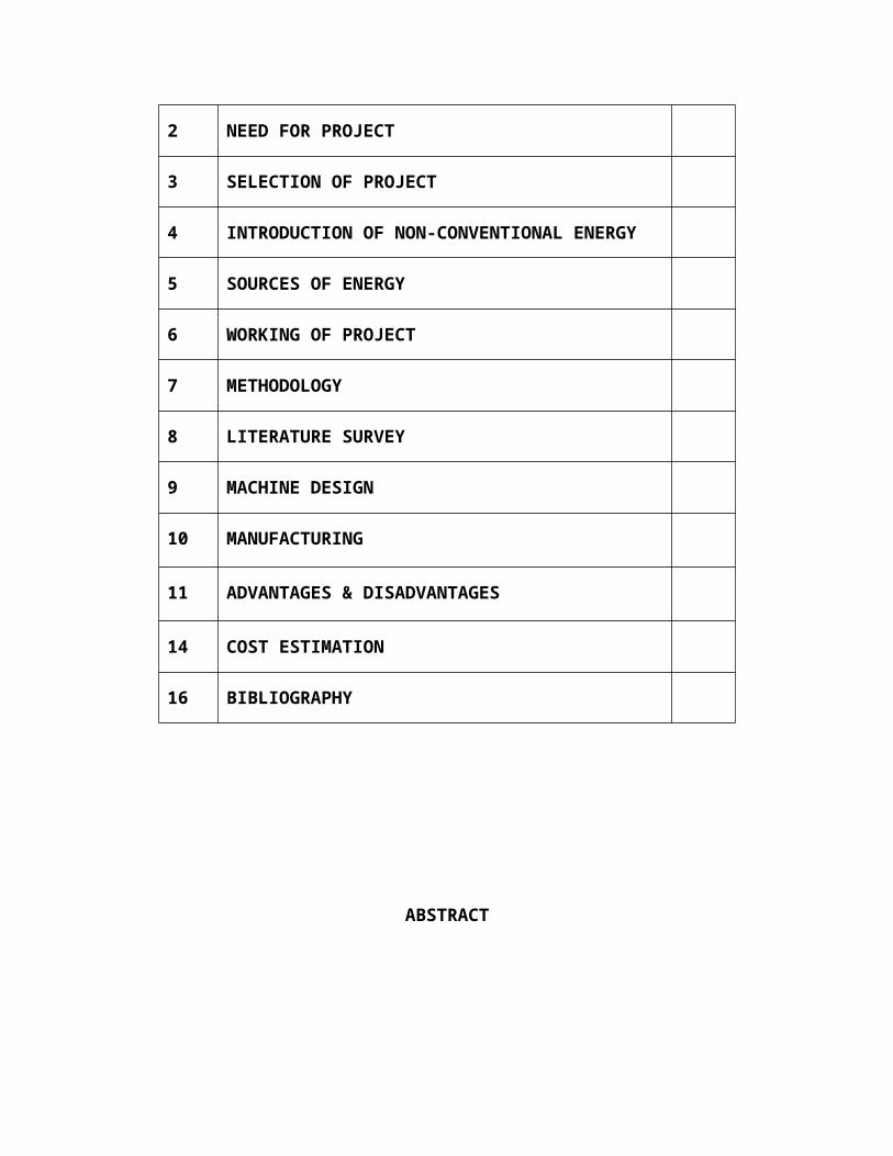
2 NEED FOR PROJECT
3 SELECTION OF PROJECT
4 INTRODUCTION OF NON-CONVENTIONAL
ENERGY
5 SOURCES OF ENERGY
6 WORKING OF PROJECT
7 METHODOLOGY
8 LITERATURE SURVEY
9 MACHINE DESIGN
10 MANUFACTURING
11 ADVANTAGES & DISADVANTAGES
14 COST ESTIMATION
16 BIBLIOGRAPHY
ABSTRACT
Through the next several decades, renewable energy technologies, thanks to their
continually improving performance and cost, and growing recognition of their Environmental,
economic and social values, will grow increasingly competitive with Traditional energy
technologies, so that by the middle of the 21st century, renewable Energy, in its various forms,
should be supplying half of the world’s energy needs."
We has selected this as our final year project so as to begin thinking towards power
generation through clean sources such as wind and wave. Power generation in our country is
very low at present. Industrially developed states like, Maharashtra is suffering through major
power shortages, and this is a signal of major crises. Even in cities like Mumbai peoples are
suffering from power cuts.
The air & wave-generator is specially planned to design and fabricate the conversion
unit for utilizing the available unconventional energy source. That is tremendously available
energy in low intensity with ample quantity can be utilized.
In this project wind & wave turbine charges a 12 volt battery and runs various 12 volt
appliances. We have fabricated the small scale wind & wave turbine on the basis of design
calculations and made changes in design to track it with manufacturing constraints.
NEED FOR PROJECT
In our country due to increased paying capacity, advanced lifestyle and
rapidly growing industrialization, the need & demand of transportation is increasing day- by-
day. The number of vehicles rolling on the road is increasing daily. Hence chances of accidents
are increasing while crossing the road especially by the children and old persons. So it became
necessary to install the speed breakers ( in true sense speed reducers) at the school building or
Hospital building- side road or highway. If these speed breakers Yes! In true sense it is speed and
ultimately breaker the opposing impact energy supplied by the hard speed breaker will apply
massive thrust impact on the soft leaf spring and suspension system of the vehicle, which
perhaps may get broken. Also it may cause damage to the occupant goods or passengers.
Hence we, the group of our class found the need of designing and
manufacturing such a system, which will make the speed breaker somewhat flexible, soft which
will not damage the vehicle more also the impact energy being absorbed by the generation
system will be utilized to convert it in to electricity rather than this hard impact transferring to
damage the suspension.
Here on working this group task we over-comed our following needs:-
we became able to have market survey
doped capability of designing a system by collecting necessary data.
Learnt actual practical fabrication processes of the sub-components of the system.
Planning the cost estimation ands budget.
Duties of a technician or an Engineer.
CHAPTER-03
SELECTION OF THE PROJECT
We the group of young engineers found that, there is an
impending need to make much more forays to make Non Conventional energy attain popular
acclaim. This is also very essential to preserve the conventional sources of energy and explore
viable alternatives like sustainable energy ( the energy which we are already utilizing but for
some safety of other uses we are suddenly wasting it, that can be reutilized), solar, wind and
biomass that can enhance sustainable growth. What is more, such alternatives are environment
friendly and easily replenish able. Therefore, they need to be thoroughly exploited with a
functionally expedient, energy matrix mix.
A engineer is always focused towards challenges of bringing ideas and
concepts to life. Therefore, sophisticated machines and modern techniques have to be constantly
developed and implemented for economical manufacturing of products. At the same time, we
should take care that there has been no compromise made with quality and accuracy.
In the age of automation machine become an integral part of human being. By
the use of automation machine prove itself that it gives high production rate than manual
production rate. In competition market everyone wants to increase their production & make their
machine multipurpose.
The engineer is constantly conformed to the challenges of bringing ideas and design into reality.
New machines and techniques are being developed continuously to manufacture various
products at cheaper rates and high quality.
Growing economies, especially of Asia are gifted with sufficient resource base
and non-conventional energy technologies are consistent both for grid linked energy generation
and transmission in out of the way locales that are islanded from the grid. Adaptation of
technology and employing them should be pursued right from this moment to have a head start,
be informed of the barriers in technology applications of the renewable variety and synergizing
them with the existing, traditional power production technology and T&D networks. It is known

AVAILABLE ENERGY OF THE MOVING VEHICLE TO APPLY IMPACT FORCE ON THE SPEED BREAKER
FLEXIBLE SPEED BREAKER TRAIN OF GEAR AND PULLEYS AND GENERATOR SYSTEM
POWER GENERTAED IN TERMA OF GLOWING BULB OR CHARGING BATTERY
that in coming times, wind energy will be the most cost-effective renewable resource. Yet, it is
doubtful if any individual technology would hold centre-stage.
Thus we selected kinetic generator means the “Energy in motion when it is
suddenly applied with a sort of obstacle, then according to Newton’s law for every action
there is an equal and opposite reaction. Utilization of this reaction is the basic reason
behind the selection of this project work.”
FIG 1: the set up flow diagram

CHAPTER -04
INTRODUCTION OF NON-CONVENTIONAL ENERGY
The development planning process designs strategies and activities to use, enhance or conserve
both natural and economic goods and services. In big modern cities, economic goods and
services almost completely replace the natural ones.
Energy is the prime source of all socio-economic activities of the human community. The
demographic rate of growth globally and the widening spectrum of economic growth would
result in demands of energy at an incremental rate of 7 to 8% annually. This can easily support a
GDP growth of 8 to 9% per annum. Projections point toward a doubling of global energy
demands in the decade starting 2020. There will be a marked shift in patterns of energy
consumption whereby developing economies of the world would have a share exceeding two-
third of global energy consumption by that period.
Fossil fuels' consumption would remain the major source of energy generation and globally
employed power generation technologies. The apportionment of renewable energy in the entire
energy supply will continue to be marginal in the real sense. The contribution of renewable
energy-excepting hydel energy and conventional biomass-as a proportion of global energy output
is pegged at a paltry 2%. This scenario in all likelihood is not going to be altered therefore,
guaranteeing the possibility of nudging the renewable contribution up to 5% by 2020. The global
sources of fossil fuel will have become dearer due to their depletion thereby, making the viability
of fossil fuel plants restoring parity with the renewable sources. 60% of the cumulated energy
needs world-wide would be met through renewable sources.
Growing economies, especially of Asia are gifted with sufficient resource base and non-
conventional energy technologies are consistent both for grid linked energy generation and
transmission in out of the way locales that are islanded from the grid. Adaptation of technology
and employing them should be pursued right from this moment to have a head start, be informed
of the barriers in technology applications of the renewable variety and synergising them with the
existing, traditional power production technology and T&D networks. It is known that in
coming times, wind energy will be the most cost-effective renewable resource. Yet, it is doubtful
if any individual technology would hold centre-stage.
It was in the 1970s that the real potential and role of renewable energy sources was sensed and
identified in India for sustainable energy growths. During the past quarter of a century, a
significant thrust has been given to the development, trial and induction of a variety of renewable
energy technologies for use in different sectors. The activities cover all major renewable energy
sources, such as biogas, biomass, solar energy, wind energy, small hydropower and other
emerging technologies.
India has presently among the world's plentiful agenda on renewable energy. in the 8th Plan, vis-
à-vis a proposal of 600 MW generation, close to 1050 MW of power generating capacity
fastened to renewable energy sources was added. About 1500 MW of the total grid capacity in
the country, is now based on renewable energy sources. India is rated fourth in the world with a
wind power capacity of 1000-1100 MW. Small hydel power generation, which is especially
ideal for remote, hilly regions, presently not exploited but holds a potential of 500 MW in today's
scenario. India has an extensive cane sugar production and we are implementing the world's
biggest biogases based cogeneration programmed in agglomeration with sugar mills. There is
substantial leverage as regards to deducing energy from urban and industrial wastes. The
National Programmes lays special emphasis on supplying energy to rural areas. Close to 2.75
million biogas plants and over 28 million upgraded wood-stoves are also in use in the country.
In the sphere of solar energy use, solar photovoltaic and solar thermal technologies are gaining
immediate reception for a host of industrial and commercial applications, as well as in Non
Electrified and Rural Zones (NERZ). The country has the world's largest assemblage of solar
photovoltaic, consisting of about 500,000 PV systems totaling to 39 MW, and encompassing
over 30 variegated operations.
There is an added emphasis on venturing into grid quality power generation Programmes
oriented on solar thermal and solar photovoltaic technologies. A 140 MW Integrated Solar
Combined Cycle (ISCC) Power Project is being accorded conclusive shape to be established at

Mathania near Jodhpur in Rajasthan. This will be the first of its kind, and the largest such project
in the world.
To give a fillip to power generation from renewable energy, State Governments and utilities
provide remunerative power purchase agreements and arrangements for wheeling, banking and
buy back of power. 12 States have so far announced policies for non-conventional energy based
power generation. The Indian Renewable Energy Development Agency (IREDA), the corporate
financing arm of the Ministry, is the only Agency of its kind in the world dedicated to financing
of renewable energy projects. Interest rates vary from 0% to 16%, with special rates being
offered for projects.
There is an impending need to make much more forays to make Non Conventional energy attain
popular acclaim. This is also very essential to preserve the conventional sources of energy and
explore viable alternatives like solar, wind and biomass that can enhance sustainable growth.
What is more, such alternatives are environment friendly and easily replenish able. Therefore,
they need to be thoroughly exploited with a functionally expedient, energy matrix mix.
A revolutionary step would be the advent of renewable energy co-operatives for power vending,
installation and servicing of renewable energy systems in pockets like NERZs. With a view to
take a long-term perspective, and to actualize the entire scope of Non-Conventional energy
sources, it is incumbent to draw up a capacious Renewable Energy Policy involving all players in
the field, together with the active participation of consumers as well
In the Ninth Plan (1997-02), the accent is on according commercialization and development of
entrepreneurship in all Renewable and Non Conventional Energy Schemes and Plans. An extra
power generating capacity from Renewable and Non Conventional Energy sources of about 1500
MW is envisaged. The immediate challenge is to reconcile the reduced budgetary allocations in
the 9th Plan due to fiscal control. The Ministry of Non Conventional Energy has stated
objective of propping up 24,000 MW from Renewable and Non Conventional Energy by the year
2012.
The need is however to have adequate policy framework to be in place with an aim to provide
impetus through streamlining the structure of Renewable and Non Conventional Energy. The

high potential is what should spur maximum efforts. The bottlenecks are that although there are
good plans, we often fall short in measuring up to meet the desired levels of optimization of our
potential. If there is a strict regiment by which Renewable and Non Conventional
Energy Sources are utilized, India is sure to have adequate measure of success. The Numero Uno
position in Renewable and Non Conventional Energy is well within reach with a little bit of
concerted effort.
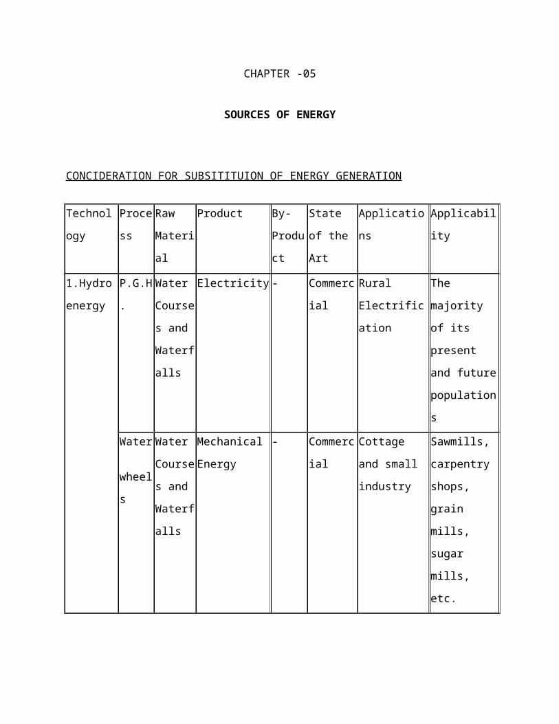
CHAPTER -05
SOURCES OF ENERGY
CONCIDERATION FOR SUBSITITUION OF ENERGY GENERATION
Technolog
y
Process Raw
Material
Product By-
Product
State of
the Art
Applications Applicability
1.Hydro
energy
P.G.H. Water
Courses
and
Waterfal
ls
Electricity - Commerci
al
Rural
Electrification
The majority
of its present
and future
populations
Water
wheels
Water
Courses
and
Waterfal
ls
Mechanical
Energy
- Commerci
al
Cottage and
small industry
Sawmills,
carpentry
shops, grain
mills, sugar
mills, etc.
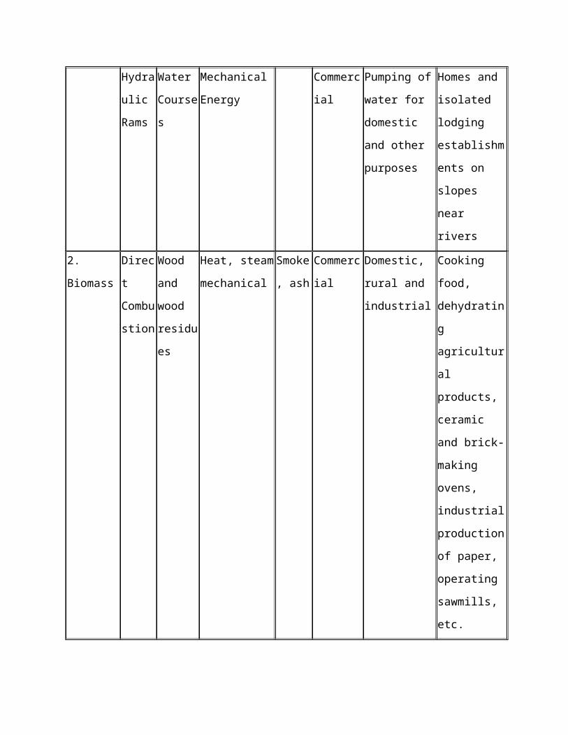
Hydrau
lic
Rams
Water
Courses
Mechanical
Energy
Commerci
al
Pumping of
water for
domestic and
other purposes
Homes and
isolated
lodging
establishments
on slopes near
rivers

2. Biomass Direct
Combu
stion
Wood
and
wood
residues
Heat, steam
mechanical
Smoke,
ash
Commerci
al
Domestic, rural
and industrial
Cooking food,
dehydrating
agricultural
products,
ceramic and
brick-making
ovens,
industrial
production of
paper,
operating
sawmills, etc.
Therm
o-
conver
sion
Wood,
cellulos
residues
Charcoal,
metallurgical
coke
(Phenol
s) Tar.
Methan
ol
acetic
acid
Commerci
al
Domestic, rural
metallurgical,
industrial
Id., also in
steel-making
and generating
electricity
Wood gas Ash.
CO2
Commerci
al and
experimen
tal
Rural and
Industrial
Ovens, boilers,
and industrial
engines,
generating
electricity
Methanol Ash,
CO2
Experime
ntal
Industry and
Transport
Chemical
industry,
vehicles
Alcoho
l
Fermen
tation
Sugar
cane,
manioc,
wood,
etc.
Ethanol lignin CO2,
pulp,
wine,
fusel
oil
neutrali
zed
acid
acid
Commerci
al and
experimen
tal (wood
ethanol)
Transport,
metallurgy, and
industry
Gasoline-
powered
vehicles,
foundries,
chemical
industry
Biomass Anaero
bic
Fermen
tation
Organic,
animal
and
plant
waste
Biogas
(methane)
Fertiliz
er,
Enviro
nmenta
l
Sanitati
on
Commerci
al and
small
scale
Energy for
domestic, rural
and industrial
(experimental)
use
Cooking food,
heating,
lighting
refrigeration,
internal
combustion
engines,
turbine/operati
on
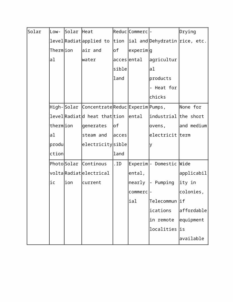
Solar Low-
level
Therm
al
Solar
Radiatio
n
Heat applied to
air and water
Reducti
on of
accessi
ble
land
Commerci
al and
experimen
tal
- Dehydrating
agricultural
products
- Heat for
chicks
Drying rice,
etc.
High-
level
thermal
product
ion
Solar
Radiatio
n
Concentrated
heat that
generates steam
and electricity
Reducti
on of
accessi
ble
land
Experime
ntal
Pumps,
industrial
ovens,
electricity
None for the
short and
medium term
Photov
oltaic
Solar
Radiatio
n
Continous
electrical
current
.ID Experime
ntal,
nearly
commerci
al
- Domestic
- Pumping
-
Telecommunic
ations in
remote
localities
Wide
applicability in
colonies, if
affordable
equipment is
available
Wind Wind-
driven
Wind Mechanical
energy
- Commerci
al
Water pumping
Grain mills,
etc.
Little, because
of scarcity of
wind
Aero-
generat
ors
Wind Continuous
electricity
Commerci
al (low
power)
and
experimen
tal (high
power)
Continuous
electricity for
domestic use
Little, because
of scarcity of
wind

COST CONCIDERATION IN ENERGY GENERATION
Potential Generation and Estimated Wholesale Cost
ResourceCost
(cents per kilowatt-hour)
Region-Wide Potential
for Generation (average
megawatts)
Hydroelectric 1.1 to 7.0 170
Chemical recovery boilers 2.6 195
Natural gas 2.7 7,400
Industrial cogeneration (natural gas) 2.7 to 6.4 4,600
Landfill gas 3.1 94
Wood residue 4.3 to 5.4 300
Geothermal 5.2 to 6.5 390 to 1,070
Wind 5.3 to 8.1 700+
Forest biomass 5.5 to 6.6 300 to 1,000
Solar thermal 8.6 ------
Solar photovoltaic (large-scale) 19.4 ------
Solar photovoltaic (small-scale) 21.5 to 23.6 ------
SOLAR ELECTRICITY

Energy from the sun can be directly converted to electricity using solar cells, also known as
photovoltaic or PVs. Today's solar electric systems have 20 to 25 year warranties, are pollution
free and can be used to offset your utility power or as stand-alone power for remote applications.
The down side to this technology is that it costs three to five times more than utility power.
BIOMASS ENERGY TECHNOLOGY has substantial potential for energy generation in
Oregon. Electricity produced from biomass grown and harvested on a sustainable basis can offset
power generation from fossil fuels and reduce net carbon dioxide emissions from the generation
of electricity in the region. Sustainable use of biomass for energy could have an increasingly
important role to play in meeting goals to reduce greenhouse gas emissions.
BARRIERS
Supply uncertainty and transportation costs have historically been barriers to greater use of forest
and agricultural residue for energy production. New technologies such as gasification combined-
cycle power generation, fuel cells using biogas as a hydrogen source, and cellulose-to-ethanol
facilities that could co generate electricity have yet to be demonstrated on a commercial scale.
The perceived risk of these newer technologies is a significant barrier, at least in the short term.
RENEWABLE ENERGY
Renewable energy is energy from any source that can be maintained in a constant supply over
time. In contrast, the supply of fossil energy sources such as oil, natural gas or coal is limited.
There are five principal renewable sources of energy: flowing water, biomass, wind, the sun and
heat from within the earth.
Heat, electricity and vehicle fuel are the main forms of energy that people use every day. All
renewable energy sources be used to produce electricity. Solar energy and geothermal energy can
supply both electricity and heat. Biomass is unique because it can supply all three forms of
usefulenergy
SUN
The sun is a constant natural source of heat and light. Sunlight can be converted to electricity.
Solar energy is energy that comes directly from the sun.
BIOMASS
"Biomass" describes, in one word, all plants, trees and organic matter on the earth. Biomass is a
source of renewable energy because the natural process of photosynthesis constantly produces
new organic matter in the growth of trees and plants. Photosynthesis stores the sun's energy in
organic matter. That energy is released when biomass is used to make heat, electricity or liquid
fuels.
WIND
The wind blows because of natural conditions of climate and geography. Historically, wind
power was used to supply mechanical energy, for example to pump water, grind grain or sail a
boat. Today, wind power is primarily a source of electricity.
WATER
Like the wind, flowing water is a product of the earth's climate and geography. Snowmelt and
runoff from precipitation at higher elevations flow toward sea level in streams and rivers. In an
earlier era, water wheels used the power of flowing water to turn grinding stones and to run
mechanical equipment. Modern hydro-turbines use water power to generate electricity.
EARTH
Heat from deep within the earth is called "geothermal energy." In some locations, geothermal
energy is close enough to the surface that, by drilling a well to reach the heat source, the energy
can be extracted and used for heating buildings and other purposes. Where the temperatures are
hot enough, geothermal energy can be used to generate electricity.
CHAPTER -06
WORKING OF PROJECT
Kino Electric Converters basically new concept of non-conventional energy generation. It is
electro-mechanical energy generating machine. This machine converts reciprocating motion in
to rotary motion. The rotational power is stored in flywheel & flywheel rotates dynamo, which
generates electricity.
Here first important point is how we get reciprocating motion, which is prime input in the
system. For that we use weight of moving vehicles that run on roads. We put our machine under
ground of road exactly below speed breaker, the head of rack is bring up to level of road surface.
When vehicles move on rack it will be pushed down. The rack is attached with free wheel type
pinion that rotates in one direction only. The rack & pinion arrangement convert reciprocating
motion in to rotary motion.
This rotary motion is further magnified using reciprocating motion in to rotary motion-belt &
pulley drive. The output of pulley is attached with flywheel, which stores kinetic energy and
transfer to dynamo, which generate electricity with zero cost.
A "generator" and "motor" is essentially the same thing: what you call it depends on whether
electricity is going into the unit or coming out of it. A generator produces electricity. In a
generator, something causes the shaft and armature to spin. An electric current is generated, as
shown in the picture (lighting bolt).Lots of things can be used to make a shaft spin - a pinwheel,
a crank, a bicycle, a water wheel, a diesel engine, or even a jet engine. They're of different sizes
but it's the same general idea. It doesn't matter what's used to spin the shaft - the electricity that's
produced is the same.

. In the case of a wind-electric turbine, the turbine blades are designed to capture the kinetic energy in wind. The rest is nearly identical to a hydroelectric setup: When the turbine blades capture wind energy and start moving, they spin a shaft that leads from the hub of the rotor to a generator. The generator turns that rotational energy into electricity. At its essence, generating electricity from the wind is all about transferring energy from one medium to another.

CHAPTER-07
METHODOLOGY
Here following method is adopted to generate the electricity:-
The set up is designed.
It’s subcomponents are manufactured
The sub components are assembled together
The set up is tested for checking whether it performing it’s intended task or not.
Under this method the flywheel is the key component for energy transformation.
FLYWHEEL
Introduction
Flywheel is a device to smoothen the cyclic fluctuation of speed
change when delivering constant output power from the engine. It has no influence
on the mear speed of the prime mover. It has no influence on the varying load
demand on the prime mover or the delivered power from the prime mover. In is the
forgoing discussion, it is observed that turning moment diagrams for the cycle
show period during which torque is in excess of the mean torque responsible for
the constant power output and also periods during which the torque is less than the
mean torque. Thus the speed of the flywheel would increase during period of
excess of torque during the cycle and the speed will fall during the period of the
deficit torque during the cycle. Thus a flywheel stores energy and releases energy
during the cycle without affecting mean energy output. Thus a properly designed

flywheel has to ensure the cyclic fluctuations of speed within prescribed limits
preferably as small as possible.
Definition of the flywheel :-
A flywheel used in machine serves as a reservoir which stores energy during the
period when the supply of energy is more than the requirement and releases it
during the period when the requirement of energy is more than the supply.
Working of the flywheel:-
The excess energy is developed during power stroke is absorbed by flywheel and
releases it to the crankshaft during the other stroke in which no energy is
developed, thus rotating the crankshaft at a uniform speed. A little consideration
will show that when the flywheel absorbs energy, its speed increases and when it
releases energy, the speed decreases. Hence a flywheel does not maintain a
constant speed, it simply reduces the fluctuation of speed. In other words, a
flywheel controls the speed variations caused by the fluctuation of the engine
turning moment during each cycle of operation.
Application:-
Flywheel are mostly used in machine where the operation is intermitted like
punching machines, shearing machines, riveting machines, crushers etc, the
flywheel stores energy from the power source during the greater portion of the
operating cycle and gives it up during a small period of the cycle. Thus the energy
from power source to the machines is supplied practically at a constant rate
throughout the operation.

CHAPTER 08
LITERATURE SURVEY
WHAT IS ELECTRICITY?
Electricity is a form of energy. Electricity is the flow of electrons. All matter is made up of
atoms, and an atom has a center, called a nucleus. The nucleus contains positively charged
particles called protons and uncharged particles called neutrons. The nucleus of an atom is
surrounded by negatively charged particles called electrons. The negative charge of an electron is
equal to the positive charge of a proton, and the number of electrons in an atom is usually equal
to the number of protons. When the balancing force between protons and electrons is upset by an
outside force, an atom may gain or lose an electron. When electrons are "lost" from an atom, the
free movement of these electrons constitutes an electric current.
Electricity is a basic part of nature and it is one of our most widely used forms of energy. We get
electricity, which is a secondary energy source, from the conversion of other sources of energy,
like coal, natural gas, oil, nuclear power and other natural sources, which are called primary
sources. Many cities and towns were built alongside waterfalls (a primary source of mechanical
energy) that turned water wheels to perform work. Before electricity generation began slightly
over 100 years ago, houses were lit with kerosene lamps, food was cooled in iceboxes, and
rooms were warmed by wood-burning or coal-burning stoves. Beginning with Benjamin
Franklin's experiment with a kite one stormy night in Philadelphia, the principles of electricity
gradually became understood. In the mid-1800s, Thomas Edison changed everyone's life -- he
perfected his invention -- the electric light bulb. Prior to 1879, electricity had been used in arc
lights for outdoor lighting. Edison's invention used electricity to bring indoor lighting to our
homes.

HOW ELECTRICITY IS MADE?
Electricity can be made or generated by moving a wire (conductor) through a magnetic field.
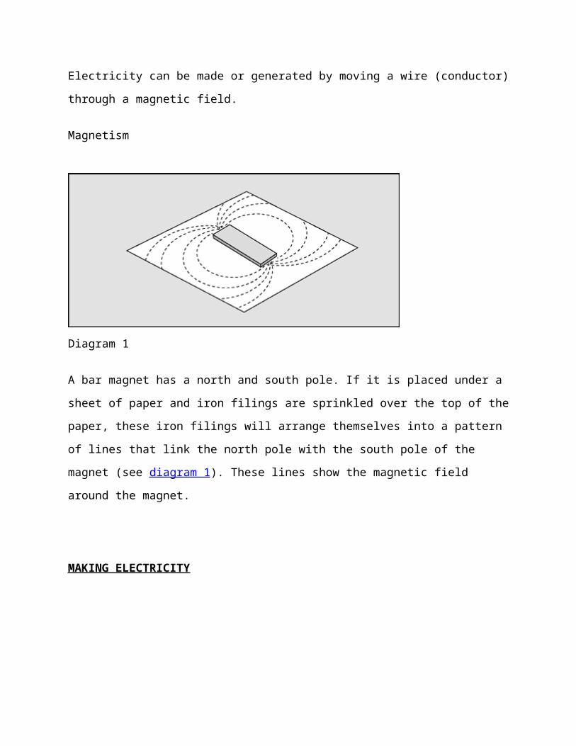
Magnetism
Diagram 1
A bar magnet has a north and south pole. If it is placed under a sheet of paper and iron filings are
sprinkled over the top of the paper, these iron filings will arrange themselves into a pattern of
lines that link the north pole with the south pole of the magnet (see diagram 1). These lines show
the magnetic field around the magnet.
MAKING ELECTRICITY

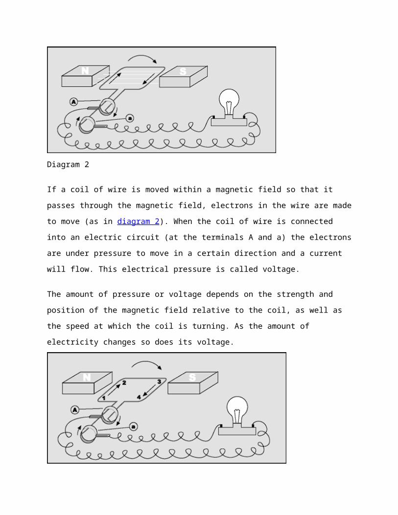
Diagram 2
If a coil of wire is moved within a magnetic field so that it passes through the magnetic field,
electrons in the wire are made to move (as in diagram 2). When the coil of wire is connected into
an electric circuit (at the terminals A and a) the electrons are under pressure to move in a certain
direction and a current will flow. This electrical pressure is called voltage.
The amount of pressure or voltage depends on the strength and position of the magnetic field
relative to the coil, as well as the speed at which the coil is turning. As the amount of electricity
changes so does its voltage.
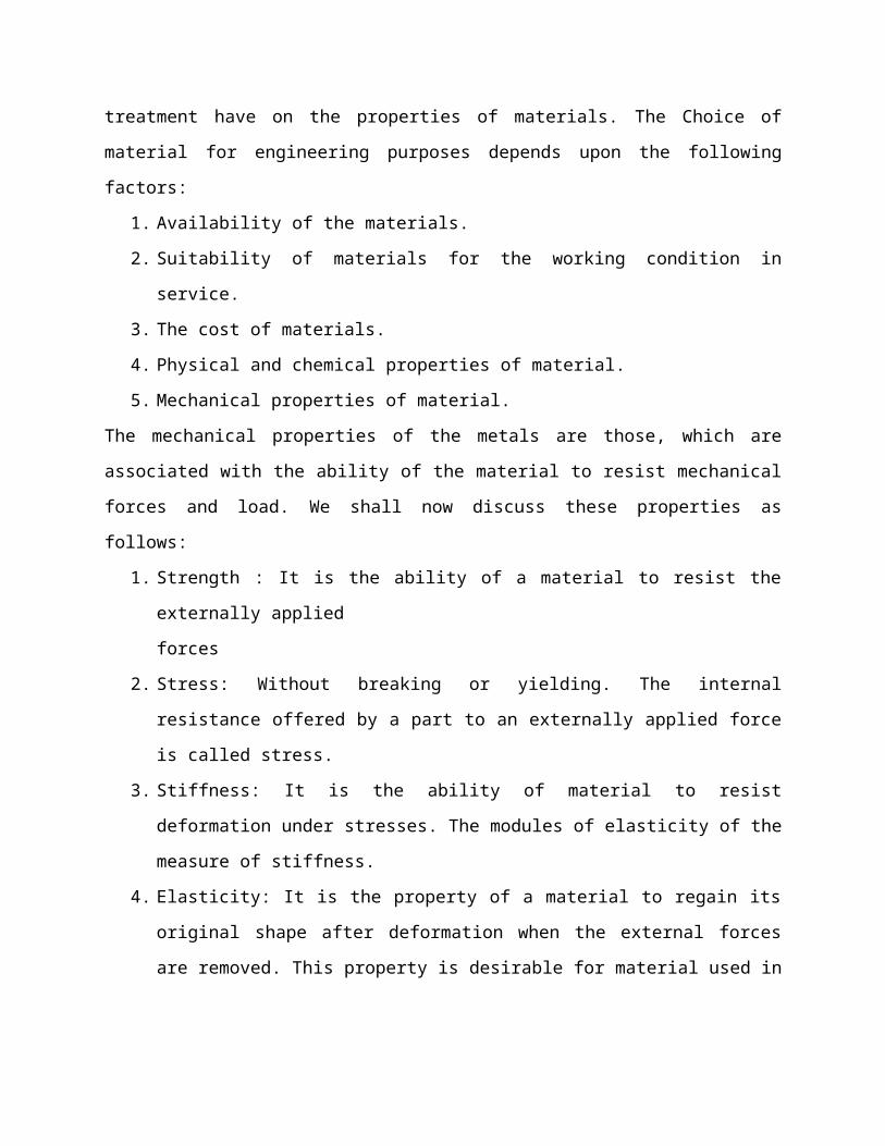
Diagram 1

Diagram 2
Diagram 3
Diagram 4

In the diagram above, the coil of wire is rotating in a clockwise direction. When the coil of wire
is in the horizontal position 1the voltage is greatest (diagram 4) because the coil is passing
through the strongest part of the magnetic field. At this stage the current flows from 1 to 2 to 3 to
4, out through terminal A, through the globe and back into terminal a. When the coil of wire is in
the vertical position (2), no electricity is produced because the coil does not cut the magnetic
field, and no current flows. When the coil of wire is in the horizontal position again 3 the voltage
is at its maximum (3), however the current flows in the opposite direction 4 to 3 to 2 to 1, out
through terminal a, through the globe, and back into terminal A.
The current produced changes direction every half turn (180 degrees ). This is called alternating
current or AC. The generators at large power stations produce nearly all the electricity we use in
this way.

CHAPTER 9
MATERIAL SELECTION
The proper selection of material for the different part of a machine is the main objective
in the fabrication of machine. For a design engineer it is must that he be familiar with the effect,
which the manufacturing process and heat treatment have on the properties of materials. The
Choice of material for engineering purposes depends upon the following factors:
1. Availability of the materials.
2. Suitability of materials for the working condition in service.
3. The cost of materials.
4. Physical and chemical properties of material.
5. Mechanical properties of material.
The mechanical properties of the metals are those, which are associated with the ability of the
material to resist mechanical forces and load. We shall now discuss these properties as follows:
1. Strength : It is the ability of a material to resist the externally applied
forces
2. Stress: Without breaking or yielding. The internal resistance offered by a part to an
externally applied force is called stress.
3. Stiffness: It is the ability of material to resist deformation under stresses. The modules of
elasticity of the measure of stiffness.
4. Elasticity: It is the property of a material to regain its original shape after deformation
when the external forces are removed. This property is desirable for material used in tools
and machines. It may be noted that steel is more elastic than rubber.
5. Plasticity: It is the property of a material, which retain the deformation produced under
load permanently. This property of material is necessary for forging, in stamping images
on coins and in ornamental work.
6. Ductility: It is the property of a material enabling it to be drawn into wire with the
application of a tensile force. A ductile material must be both strong and plastic. The
ductility is usually measured by the terms, percentage elongation and percent reduction in

area. The ductile materials commonly used in engineering practice are mild steel, copper,
aluminum, nickel, zinc, tin and lead.
7. Brittleness: It is the property of material opposite to ductile. It is the
Property of breaking of a material with little permanent distortion. Brittle materials when
subjected to tensile loads snap off without giving any sensible elongation. Cast iron is a
brittle material.
8. Malleability: It is a special case of ductility, which permits material to be rolled or
hammered into thin sheets, a malleable material should be plastic but it is not essential to
be so strong. The malleable materials commonly used in engineering practice are lead,
soft steel, wrought iron, copper and aluminum.
9. Toughness: It is the property of a material to resist the fracture due to high impact loads
like hammer blows. The toughness of the material decreases when it is heated. It is
measured by the amount of absorbed after being stressed up to the point of fracture. This
property is desirable in parts subjected to shock an impact loads.
10. Resilience: It is the property of a material to absorb energy and to resist rock and impact
loads. It is measured by amount of energy absorbed per unit volume within elastic limit.
This property is essential for spring material.
11. Creep: When a part is subjected to a constant stress at high temperature for long period of
time, it will undergo a slow and permanent deformation called creep. This property is
considered in designing internal combustion engines, boilers and turbines.
12. Hardness: It is a very important property of the metals and has a wide
verity of meanings. It embraces many different properties such as resistance to wear
scratching, deformation and mach inability etc. It also means the ability of the metal to cut
another metal. The hardness is usually expressed in numbers, which are dependent on the
method of making the test. The hardness of a metal may be determined by the following test.
a) Brinell hardness test
b) Rockwell hardness test
c) Vickers hardness (also called diamond pyramid) test and
d) Share scaleroscope.
The science of the metal is a specialized and although it overflows in to realms of knowledge it
tends to shut away from the general reader. The knowledge of materials and their properties is of

great significance for a design engineer. The machine elements should be made of such a
material which has properties suitable for the conditions of operations. In addition to this a
design engineer must be familiar with the manufacturing processes and the heat treatments have
on the properties of the materials. In designing the various part of the machine it is necessary to
know how the material will function in service. For this certain characteristics or mechanical
properties mostly used in mechanical engineering practice are commonly determined from
standard tensile tests. In engineering practice, the machine parts are subjected to various forces,
which may be due to either one or more of the following.
1. Energy transmitted
2. Weight of machine
3. Frictional resistance
4. Inertia of reciprocating parts
5. Change of temperature
6. Lack of balance of moving parts
The selection of the materials depends upon the various types of stresses that are set up during
operation. The material selected should with stand it. Another criteria for selection of metal
depend upon the type of load because a machine part resist load more easily than a live load and
live load more easily than a shock load.
Selection of the material depends upon factor of safety, which in turn depends upon the
following factors.
1. Reliabilities of properties
2. Reliability of applied load
3. The certainty as to exact mode of failure
4. The extent of simplifying assumptions
5. The extent of localized
6. The extent of initial stresses set up during manufacturing
7. The extent loss of life if failure occurs
8. The extent of loss of property if failure occurs

Material used
Mild steel
Reasons:
1. Mild steel is readily available in market
2. It is economical to use
3. It is available in standard sizes
4. It has good mechanical properties i.e. it is easily machinable
5. It has moderate factor of safety, because factor of safety results in unnecessary wastage
of material and heavy selection. Low factor of safety results in unnecessary risk of failure
6. It has high tensile strength
7. Low co-efficient of thermal expansion
PROPERTIES OF MILD STEEL:
M.S. has a carbon content from 0.15% to 0.30%. They are easily wieldable thus can be hardened
only. They are similar to wrought iron in properties. Both ultimate tensile and compressive
strength of these steel increases with increasing carbon content. They can be easily gas welded or
electric or arc welded. With increase in the carbon percentage weld ability decreases. Mild steel
serve the purpose and was hence was selected because of the above purpose
BRIGHT MATERIAL:
It is a machine drawned. The main basic difference between mild steel and bright metal is that
mild steel plates and bars are forged in the forging machine by means is not forged. But the
materials are drawn from the dies in the plastic state. Therefore the material has good surface
finish than mild steel and has no carbon deposits on its surface for extrusion and formation of
engineering materials thus giving them a good surface finish and though retaining their metallic
properties
ADVANTAGES
Following are the benefits of the wind mill
Clean source of energy.
No fuel costs
Inexpensive
Local transmission
Green pricing
Using of small wind turbine will make residential societies independent from other
sources of power.
Running cost is low. [2].
Dynamos
In simplest terms, a dynamo is essentially an electric motor run in reverse. The electric motor uses magnets spinning in a metal coil to spin an axle. Conversely, spinning the axle causes the magnets to rotate in the coil and generates an electric current moving away from the motor. A cool experiment to try is to buy a small motor from radio shack and put it to your tongue. Spin it and you will feel a slight tingle coming from the connectors. This is known as the Faraday effect. Look up this effect to gain a fuller understanding of motors and dynamos.
In physics, a simple generator or machine for transforming mechanical energy into electrical energy. A dynamo in basic form consists of a powerful field magnet between the poles of which a suitable conductor, usually in the form of a coil (armature), is rotated. The magnetic lines of force are cut by the rotating wire coil, which induces a current to flow through the wire. The mechanical energy of rotation is thus converted into an electric current in the armature.
Present-day dynamos work on the principles described by English physicist Michael Faraday in 1830, that an electromotive force is developed in a conductor when it is moved in a magnetic field. The dynamo that powers the lights on a bicycle is an example of an alternator, that is, it produces alternating current (AC).
How does dynamo work?
But at the lowest level, if you move a conductor such as wire across a magnetic field, it generates a current in the wire. All dynamos are just different way of packaging up a lot of wires and moving them fast in a magnetic field. There are lots of subtleties, but the underlying physics is the same
uses a permanent magnet which is rotated by a crank. The spinning magnet is positioned so that its north and south poles passed by a piece of iron wrapped with wire. It was discovered that the spinning magnet produced a pulse of current in the wire each time a pole passed the coil. Furthermore, the north and south poles of the magnet induce currents in opposite directions. By adding a commutator, it is possible to convert the alternating current to direct current.
In my view, and in the view of many bicycle safety experts, dynamos are usually not an attractive option. This is for reasons of both cost and performance. Decent dynamo light sets are much more costly than decent battery powered lights, and the battery powered lights have vastly superior illumination than even the most expensive dynamo powered system. The problem is that a dynamo driven by a bicycle is very limited in the amount of power that can be generated.

The Attraction to Dynamo Powered Lights
The attraction of dynamo powered lights is obvious; you are self-sufficient and there is no limit to the duration that the lights can be used. Some individuals believe that having to rely on mains power for bicycle lighting is somehow cheating. Purists may be willing to spend the additional money for a high end, 6 watt, dynamo system, or live with the lower performance and lower safety provided by a 3 watt dynamo powered system. Of course a few of these people will hotly dispute the contention that a 3 watt system is less safe than a higher power system, but the bicycle safety experts do not agree with this contention.
In well lit cities where the cyclist is familiar with their route, a dynamo system is often sufficient. However due to the power generation limits of a bicycle dynamo, it simply is not possible to generate enough power for lights that are bright enough for use on dark or unfamiliar routes. Another factor is that as we age, our night vision deteriorates, and brighter lighting is necessary for safety. Personally, I do own a dynamo. It's fine for going around a familiar town at night, and eliminates the need to worry about batteries. However I would never use it on dark or unfamiliar routes.
Design calculations
Designing of wind mill
Before going to actual designing we must consider following points
Suitable site
Types of wind mill
Aerodynamics design
Overall design of wind mill
Suitable site
While selection of suitable site we must keep a note that it must be placed where plenty of
air flows without obstructions i.e. at a certain elevated height.
Types of wind mill
From different types of wind mill the multiback flow is selected. As we have sufficient
speedy air and also losses for this type of wind mill is minimum.
Aerodynamics design
While studying on the design of wind mill we come to conclusion that blade should be kept
in a certain angle to still away the momentum from the approaching wind.
Thus the wind come horizontally hits the blade which is kept at fixed angle.
Overall design of wind mill
Designs of the components as follows,
4.1 Power capacity
Calculation of Wind Energy and Power
Force = mass x acceleration F = ma (Typical Unit -Newton’s)
Energy = Work (W) = Force (F) x Distance (d) (Typical unit – Joules)
Power = P = W / time (t) (Typical unit –Watts)
Power = Torque (Q) x Rotational Speed (Ω)
Kinetic Energy in the Wind
Kinetic Energy = Work = ½MV2
Where:
M= mass of moving object
V = velocity of moving object
Mass of moving air
M = density (ρ) x volume (Area x distance)
= ρ x A x d
= (kg/m3) (m2) (m)
= kg
Power in the Wind
Power = Work / t
= Kinetic Energy / t
= ½MV2 / t
= ½(ρ x A x d) V2/t
= ½ρAV2 (d/t) (d/t = Distance/time = velocity)
= ½ρAV3
Power in the Wind = ½ρAV3
V = 40 kilo meter per hours = 11.11 m/s
V = 12 meters (m) per second (s) m/s
ρ = 1.0 kg/m3
Selecting Rotor diameter, D = 0.15 m.
Rotor radius (Length of blade), R = 0.07 m
A = (∏/4) x D2 = (∏/4) x (0.15)2 = 0.018 m2
Power in the Wind = ½ρAV3
Units = (kg/m3) x (m2) x (m3/s3)
= (kg-m)/s2 x m/s
= N-m/s
= Watt
Wind Turbine actual Power available considering losses and efficiency: -
Power in the Wind = 0.5 x ρ x A x V3 x Cp x Ng x Nb [1].
Where:
P = power in watts
ρ = air density
A = rotor swept area, exposed to the wind (0.018 m2)
Cp = Coefficient of performance (Cp is the percentage of power in the wind that
is converted into mechanical energy, 0.59 {Betz limit} is the maximum
theoretically, 0.35 practically)
V = wind speed in meters/sec (12 m/s)
Ng = generator efficiency (practically 75%)

Nb = gearbox & bearings efficiency (Assuming 75%).
Hence,
P = 0.5 x 1 x 0.018 x 0.35 x (12)3 x 0.75 x 0.75 = 3.06 Watts
POWER CAPACITY = 3 Watts

COMPONENT: FRAME CHANNEL
MATERIAL:- M.S. CHANNEL
MATERIAL SPECIFICATION:-I.S.L.C. 40X.75X5
SR. NO
DESCRIPTION OF OPERATION
MACHINE USED
CUTTING MEASUREMENT TIME
1 Cutting the channel in to length as per dwg
Gas cutting machine
Gas cutterSteel rule
15min.
2 Cutting the channel in to length as per dwg
Gas cutting machine
Gas cutter Steel rule 15min.
3 Filing operation can be performed on cutting side and bring it in perpendicular C.S.
Bench vice File Try square 15 min.
4 Weld the channels to the required size as per the drawing
Electric arc welding machine
------- Try square 20 min
5 Drilling the frame at required points as per the drawing.
Radial drill machine
Twist drill Vernier calliper 10 min.

NAME OF THE PART – SHAFT
MATERIAL – BRIGHT STEEL
QUANTITY – 1
SR.NO. DETAIL
OPER.
M/C.
USED
TOOL
USED
ACCES MEA.INST.
1. Marking on
shaft
- - - Scale
2. Cutting as
per dwg
Power
hack saw
Hock saw
blade
Jig &
fixtures
Scale
3. Facing both
side of shaft
Lathe
machine
Single
point
cutting
tool
Chuck Vernier
caliper
4. Turning as
per dwg size
- - - -
5. Filling on
both end
Flat file Vice -
Chapter 12
Testing and Results
Readings:
Using 12 Volts generator and rated power is 36watts.
SR no.
Wind speedm/s
Speed of shaftrpm
VoltageV
CurrentA
Powerwatts
1 1 to 1.5 82 to 90 3.2 1.1 3.52
2 1.5 to 2.5 109 to 121 3.9 1.3 5.07
3 2.5 to 3.5 189 to 201 4.8 1.4 6.72
4 3.5 to 4.5 271 to 320 6.2 1.9 11.78
5 4.5 to 5.5 328 to 353 8.8 2.4 21.12
6 5.5 to 6.5 390 to 396 9.2 2.7 24.84
7 6.5 to 7 400 to 409 12 3 36

Power curve:
Fig.7.1 Power curve

Cost estimation
Material cost:
Material Specification QuantityCost(Rs.)
Turbine blade 23” dia 3 3500
shaft 20 mm dia 1 390
Pedestal bearing P204 2 600
frame 75 x 40 x 4 mm C section
1 4000
pulley 250 mm 1 350
dynamo 36 watt 1 300
blower 1/8 hp 1 2200
Chain and sprocket std 1 800
Total Material cost = 11840 Rs.
Machining cost:
Machine used Total operation time
Cost/hr(‘Rs.’)
Total cost
(‘Rs.’)welding 2 Hrs. 45 min. 30 500
Drilling 1 Hrs. 15 50
Total Machining cost = 550 Rs.
Miscellaneous cost = 500 Rs
CHAPTER NO 13
BIBLIOGRAPHY
[1] Website: www.wikipedia.com.
[2] Website: www.powertechnology.com.
[3] Website: www.howstuffwork.com .
[4] Dr. Eric Eggleston, “Sources of Energy”, 2nd Edition, 2001.
[5] R.S Khurmi, J.K Gupta, “Machine Design”
[6] K.L.Kumar, “Fluid Mechanics”, 8th Edition, 2005.
[7] S.Ramamrutham, R.Narayanan, “Strength of Materials”, 6th Edition, 2002.
[8] P.S.G, “Design data Book”, 2nd compiled Edition, 2006.
[9] Domkundwar, “Power plant engineering”, 5th Edition, 2003.