air-to-water heat pump serie - sinclair-solutions.com · air-to-water heat pump installation manual...
TRANSCRIPT
Installation Manual
Air-to-water Heat PumpSERIE
GSH-60IRA GSH-60ERA GSH-80IRA GSH-80ERA GSH-100IRA GSH-100ERA GSH-120IRA GSH-120ERA GSH-140IRA GSH-140ERA GSH-160IRA GSH-160ERA
GSH-120IRA-3 GSH-120ERA-3 GSH-140IRA-3 GSH-140ERA-3 GSH-160IRA-3 GSH-160ERA-3
Operational Manual


AIR-TO-WATER HEAT PUMP INSTALLATION MANUAL
Contents
1. Instruction to Users--------------------------------------------------------------------------------2 2. Safety Considerations-----------------------------------------------------------------------------3 3. Diagram of the Operating Principle-------------------------------------------------------------6 4. Operating Principle of the Unit------------------------------------------------------------------6 5. Model Line-Up --------------------------------------------------------------------------------------9 6. Installation Example-----------------------------------------------------------------------------10 7. Main components--------------------------------------------------------------------------------13 8. Installation Guideline of the unit---------------------------------------------------------------16 9. Installation of Indoor Unit-----------------------------------------------------------------------19 10. Connection of pipeline-------------------------------------------------------------------------26 11. Remote Air Temperature Sensor--------------------------------------------------------------29 12. Thermostat --------------------------------------------------------------------------------------31 13. 2-Way Valve-------------------------------------------------------------------------------------32 14. 3-Way Valve-------------------------------------------------------------------------------------33 15. Gate-controller----------------------------------------------------------------------------------3416 Filling of Refrigerant ---------------------------------------------------------------------------3417. Installation of Insulated Water Tank ---------------------------------------------------------35 18 Wring Diagram-----------------------------------------------------------------------------------4019. Debugging Operation of Unit-----------------------------------------------------------------5220. Daily Operation and Maintenance------------------------------------------------------------5421. Parameter Lists----------------------------------------------------------------------------------57
1

AIR-TO-WATER HEAT PUMP INSTALLATION MANUAL
1. Instruction to Users Thank you for choosing our Air to water Heat Pump. Please read this manual carefully before installation and use the unit correctly according to the following procedure.
After receipt of the unit, check it for appearance, unit model compared with your desire
and attachments.
For proper installation and future maintenance please read this Instruction and keep it
carefully.
Design and installation work of the unit must be performed by authorized personnel
according to applicable laws and regulations and this Instruction.
After installation work, the unit can not be energized unless there is not any problem in
check.
Ensure periodical clean and maintenance of the unit after normal operation of the unit for
longer life and reliable operation.
For improvement of products, there should be not additional notice of amendment of the
contents.
This appliance is not intended for use by persons (including children) with reduced
physical, sensory or mental capabilities, or lack of experience and knowledge, unless they
have been given supervision or instruction concerning use of the appliance by a person
responsible for their safety.
Children should be supervised to ensure that they do not play with the appliance.
Notice!
This product must not be disposed together with the domestic waste. This product has to
be disposed at an authorized place for recycling of electrical and electronic appliances.
!
2

AIR-TO-WATER HEAT PUMP INSTALLATION MANUAL
2. Safety Considerations
Please read the following contents carefully before operating.
WARNING
★ Once abnormality like burning smell occurs, please cut off the power supply immediately and then contact with service center.
If the abnormality still exists, the unit may be damaged and electric shock or fire may result.
★ Don't operate the unit with wet hand.
Otherwise, it may cause electric shock.
★ Before installation, please see if the voltage of local place accords with that on nameplate of unit and capacity of power supply, power cord or socket is
suitable for input power of this unit.
★ Special circuit must be adopted for power supply to prevent fire.
Do not use octopus multipurpose plug or mobile terminal board for wire connection.
★ Be sure to pull out the power plug and drain the indoor unit and water tank when unit is not in use for a long time.
Otherwise, the accumulated
dust may cause overheating, fire or freeze of water tank or coaxial heater exchanger in winter.
★ Never damage the electric wire or use the one which is not specified.
Otherwise, it may cause overheating or fire.
3

AIR-TO-WATER HEAT PUMP INSTALLATION MANUAL
★ Before cleaning please cut off the power supply.
Otherwise, it may cause electric shock or damage.
★ The power supply must adopt special circuit with leakage switch and enough capacity.
★ User can not change power cord socket without prior consent. Wiring working must be done by professionals. Ensure good earthing and don't change earthing mode of unit.
★ Earthing: the unit must be earthed reliably ! The earthing wire should connect with special device of buildings.
If not, please ask the qualified personnel to install. Furthermore, don't connect earth wire to gas pipe, water pipe, drainage pipe or any other improper places which professional does not recognize.
★ Never insert any foreign matter into uint to avoid damage . And never insert your hands into the air outlet of outdoor unit.
★ Don't attempt to repair the unit by yourself.
Improper repair may cause electric shock or fire, so you should contact the service center to repair.
★ Don't step on the top of the unit or place anything on it.
There is the danger of fall of things or people.
★ Never block the air inlet and outlet of unit.
It may reduce efficiency or cause stop of the unit and even fire.
★ Keep pressurized spray, gas holder and
so on away from the unit above 1m .
It may cause fire or explosion.
4

AIR-TO-WATER HEAT PUMP INSTALLATION MANUAL
★ Please note whether the installation stand is firm enough or not.
If damaged, it may cause fall of the unit and injury of people.
★ unit should be installed at the place with good ventilation to save energy.
★ When there is not water in water tank, never power the unit on to run.
Notice! 1、Before installation, please check if the adopted power is accordance with that listed
on nameplate, and check the safety of power.
2、Before using, please check and confirm if wires and water pipes are connected correctly to
avid water leakage, electric shock or fire etc.
3、Don’t operate the unit with wet hand, and don’t allow children to operate the unit.
4、The On/off in the instruction is for the operation to on and off button of PCB for users; cut off
power means to stop supplying power to the unit.
5、Don’t directly expose the unit under the corrosive ambient with water or dampness.
6、Don’t operate the unit without water in water tank .The air outlet/inlet of unit can not be
blocked by other objects.
7、The water in unit and pipeline should be discharged if the unit is not in use, to prevent the
water tank, pipe line and water pump from frost-cracking.
8、 Never press the button with sharp objects to protect manual controller. Never use other
wires instead of special communication line of the unit to protect control elements. Never
clean the manual controller with benzene, thinner or chemical cloth to avoid fading of
surface and failure of elements. Clean the unit with the cloth soaked in neutral
eradicator .Slightly clean the display screen and connecting parts to avoid fading.
9、The power cord must be separated with the communication line.
If there is any question, please contact with local dealer, authorized
service center, agencies or our company directly.
!
5

AIR-TO-WATER HEAT PUMP INSTALLATION MANUAL
3. Diagram of the Operating Principle
INDOOR UINTOUTDOOR UINT
M
M
M
M
1
2
3
45
6
7
8
10
11
5
12
1 compressor2 four-way valve3 finned coil exchanger4 fan motor5 filter6 electronic expansion valve7 plate heat exchanger
11 flow switch10 electric heater
9 air-vent valve
8 pump
12 3-way valve
t
R1T
R3Tt
R5Tt
R4Tt
t
R2T
9
t R6T
t R7T
R7T water tank temperature sensor 2
R5T leaving water temperature sensor
R2T Liquid line temperature sensor
R1T plate outlet temperature sensor
R4T returning water temperature sensor
R6T water tank temperature sensor 1
R3T gas line temperature sensor
13
14
15 16
17
18
19
20
13 2-way valve14 by-pass valve15 under-floor heating16 radiator17 other thermal system18 water tank
19 expansion tank20 safety valve
4.Operating Principle of the Unit
DC Inverter Air to Water Heat Pump is composed of outdoor unit, indoor unit and
internal-fan coil water tank. Operation functions:
1. Cooling;
2. Heating;
3. Water heating;
4. Cooling +water heating;
5. Heating+ water heating;
6. Emergency mode;
7. Quick water heating;
8. Holiday mode;
9. Forced Operation Mode;
10. Silent mode;
11. Disinfection mode;
12. Weather-dependent Operation;
Cooling: in cooling mode:the refrigerant is condensed in the outdoor unit and evaporated in the indoor unit. Via the heat exchange with water in the indoor unit, the
6

AIR-TO-WATER HEAT PUMP INSTALLATION MANUAL
CASE 2: connecting Sanitary Water Tank
1. In this case, three-way valve should be installed and should be complied with installation of this
manual; 2. Sanitary water tank should be equipped with internal electric heater to to secure enough heat
energy in the very cold days;
B
Under-floor coil
Outdoor Indoor
Sanitary Water Tank
booster heater
T
11

AIR-TO-WATER HEAT PUMP INSTALLATION MANUAL
temperature of water decrease and it releases heat while the refrigerant absorbs heat and evaporates. With the help of wired controller, the outflow temperature can meet the user’s requirement. Through the control of valve, the low-temperature water in the system is connected with indoor fan coil and underground pipe, and exchanges heat with the indoor air so that the indoor temperature decreases to the required range.
Heating: in heating mode: the refrigerant evaporates in the outdoor unit and is
condensed in the indoor unit. Via the heat exchange with water in the indoor unit, the water absorbs heat and its temperature increase while the refrigerant releases heat and is condensed. With the help of wired controller, the outflow temperature can meet the user’s requirement. Through the control of valve, the high-temperature water in the system is connected with indoor fan coil and underground pipe, and exchanges heat with the indoor air so that the indoor temperature increases to the required range;
Water heating: in water heating mode,the refrigerant evaporates in the outdoor unit
and is condensed in the indoor unit. Via the heat exchange with water in the indoor unit, the water absorbs heat and its temperature increase while the refrigerant releases heat and is condensed. With the help of wired controller, the outflow temperature can meet the user’s requirement. Through the control of valve, the high-temperature water in the system is connected with the coil pipe of bearing water tank, and exchanges heat with the water in the water tank so that the temperature of water tank increases to the required range;
Cooling +water heating: when cooling mode exists together with the water heating
mode, the user can set the priority of these two modes based on the needs. The default priority is heat pump. That is under the default setting, if cooling mode exists together with the water heating mode, the heat pump gives priority to cooling. In that case, water heating can only realized with e-heater of the water tank. Inversely, the heat pump gives priority to water heating and switches to cooling after finishing water heating;
Heating+ water heating: when heating mode exists together with the water heating
mode, the user can set the priority of these two modes based on the needs. The default priority is heat pump. That is under the default setting, if heating mode exists together with the water heating mode, the heat pump gives priority to heating. In that case, water heating can only realized with e-heater of the water tank. Inversely, the heat pump gives priority to water heating and switches to heating after finishing water heating;
Emergency mode: this mode is only available for heating and water heating. When
the outdoor unit stops due to malfunction, enter the corresponding emergency mode; as to heating mode, after entering the emergency mode, heating can only be realized through e-heater of the indoor unit. When the setting outflow temperature or indoor temperature is reached, the e-heater of indoor unit will stop running; as to water heating mode, the e-heater of indoor unit stops while the e-heater of water tank runs. When the setting temperature or water tank is reached, the e-heater will stop running;
7

AIR-TO-WATER HEAT PUMP INSTALLATION MANUAL
Quick water heating: in quick water heating mode, the unit runs according to the water heating control of heat pump and the e-heater of water tank runs at the same time;
Forced Operation Mode: this mode is only used for refrigerant recovery and
debugging for the unit; Holiday mode: this mode is only available for heating mode. This mode is set to keep
indoor temperature or leaving water temperature in a certain range, so as to prevent water system of the unit from freezing or protect certain indoor articles from freezing damage. When the outdoor unit stops due to malfunction, the two e-heaters of the unit will run.
Disinfection mode: in this mode, the water heating system can be disinfected. When
starting up the disinfection function and setting corresponding time to meet the requirement of disinfection mode, the function will start. After the setting temperature is reached, this mode will terminate.
Weather-dependent Operation: this mode is only available for space heating. In Weather-dependent mode, the setting value (remote room air temperature or leaving water temperature)is detected and controlled automatically when the outdoor air temperature is changed.
Silent mode: Silent mode is available in cooling, heating and water heating mode. In
silent mode, the outdoor unit will reduce the running noise via automatic control.
8

AIR-TO-WATER HEAT PUMP INSTALLATION MANUAL
5. Model Line-Up
Capacity
Model Name Heating,KW Cooling,KW
Power supply
161 15.52
14 15
12 14
10 10.5
8.5 9.0
6.2 5.5
220-240V
1Ph~ 50Hz
151 15.52
14 15
12 14
380-415V 3Ph~ 50Hz
GSH-160IRA GSH-160ERA
GSH-140IRA GSH-140ERA
GSH-120IRA GSH-120ERA
GSH-100IRA GSH-100ERA
GSH-80IRA GSH-80ERA
GSH-60IRA GSH-60ERA
GSH-160IRA-3 GSH-160ERA-3
GSH-140IRA-3 GSH-140ERA-3
GSH-120IRA-3 GSH-120ERA-3
Note:
1 Capacities and power inputs are based on the following conditions: Indoor Water Temperature 30°C/35°C,Outdoor Air Temperature 7°CDB/6°CWB;
2 Capacities and power inputs are based on the following conditions: Indoor Water Temperature 23°C/18°C,Outdoor Air Temperature 35°CDB/24°CWB
9

AIR-TO-WATER HEAT PUMP INSTALLATION MANUAL
6. Installation Example CASE 1: connecting Under-floor coil for heating and cooling
1. Type of thermostat and specification should be complied with installation of this manual;
2. By pass valve must be installed to secure enough water flow rate,and by pass valve should be
installed at the collector;
Under-floor coil
Outdoor Indoor
T
B
10

AIR-TO-WATER HEAT PUMP INSTALLATION MANUAL
CASE 3 : connecting Sanitary Water Tank and Heat Emitters for heating and Cooling;
Two-way valve is very important to prevent dew condensation on the floor and Radiator while
cooling mode.
B
Outdoor Indoor
Sanitary Water Tank
booster heater FCU 1 FCU2
M
Radiator
T
Under-floor coil
12

AIR-TO-WATER HEAT PUMP INSTALLATION MANUAL
7. Main components 7.1 Indoor units
External
Water pump
Expansion Tank
Flow Switch
Plate Heat Exchanger
Control Box
Electric Heater
Control Panel
Safety Valve Air Vent
Internal
Water pressure gage
GSH-60IRAGSH-80IRAGSH-100IRAGSH-120IRAGSH-140IRAGSH-160IRA
GSH-120IRA-3GSH-140IRA-3GSH-160IRA-3
13

AIR-TO-WATER HEAT PUMP INSTALLATION MANUAL
7.2. Outdoor unit 7.2.1 GSH-60ERA, GSH-80ERA,GSH-100ERA
External
Internal
Control Box
DC Fan Motor
Compressor
14

AIR-TO-WATER HEAT PUMP INSTALLATION MANUAL
7.2.2 GSH-120ERA, GSH-140ERA, GSH-160ERA GSH-120ERA-3, GSH-140ERA-3, GSH-160ERA-3
External
Internal
Control Box
DC Fan Motor
Compressor
15

AIR-TO-WATER HEAT PUMP INSTALLATION MANUAL
8.Installation Guideline of the unit 8.1 Instruction to installation
The installation of unit must be in accordance with national and local safety codes. Installation quality will directly affect the normal use of air conditioner unit. The user is
prohibited from installation by himself. Please contact your dealer after buying this machine. Professional installation workers will provide installation and test services according to installation manual.
Do not connect to power until all installation work is completed.
8.2 Installation of Outdoor Unit 8.2.1 Select Installation Location of Outdoor Unit
Outdoor unit must be installed on a firm and solid support. Outdoor unit shall be installed close to the indoor unit, hence to minimize the length and
bends of cooling pipe. Avoid placing the outdoor unit under window or between two constructions, hence to
prevent normal operating noise from entering the room. Air flow at inlet and outlet shall not be blocked. Install at a well-ventilated place, so that the machine can absorb and discharge sufficient
air. Do not install at a place where flammable or explosive goods exist or a place subject to
severe dust, salty fog and polluted air. 8.2.2 Outline dimension of outdoor unit
GSH-60ERA, GSH-80ERA, GSH-100ERA
16

AIR-TO-WATER HEAT PUMP INSTALLATION MANUAL
Description Unit: inch
No Name Remarks
3/8 1 Liquid-side Service Valve 1/4
5/8 2 Gas-side Service Valve 1/2
3 Handle Used to cover or uncover the front case 4 Air discharge Grill /
8.2.2 Space requirements for installation
GSH-120ERA, GSH-140ERA, GSH-160ERA GSH-120ERA-3, GSH-140ERA-3, GSH-160ERA-3
GSH-80,100,120,140,160IRA/ERA
GSH-60IRA/ERAGSH-120,140,160IRA/ERA-3
GSH-80,100,120,140,160IRA/ERA
GSH-60IRA/ERAGSH-120,140,160IRA/ERA-3
17

AIR-TO-WATER HEAT PUMP INSTALLATION MANUAL
8.2.3 Precautions on Installation of Outdoor Unit When moving outdoor unit, it is necessary to adopt 2 pieces of long enough rope to hand
the unit from 4 directions. Included angle between the rope when hanging and moving must be 40°below to prevent center of the unit from moving.
Adopt M12 bolts components to tighten feet and under frame when installing. Outdoor unit should be installed on concrete base that is 10cm height. Requirements on installation space dimension of unit’s bodies are shown in following
drawing. Outdoor unit must be lifted by using designated lifting hole. Take care to protect the unit
during lift. To avoid rusting, do not knock the metal parts.
18

AIR-TO-WATER HEAT PUMP INSTALLATION MANUAL
9. Installation of Indoor Unit 9.1 Select Installation Location of Indoor Unit
Avoid direct sunshine. Ensure the hanger rod, ceiling and building structure have sufficient strength to support
the weight of air conditioner unit. Drainage pipe is easy to connect out. Indoor and outdoor connection pipes are easy to go outdoors Do not install at a place where flammable or explosive goods exist or flammable or
explosive gas might leak.
Do not install at a place subject to corrosive gas, severe dust, salty fog, smoke or heavy
moisture.
Air flow at inlet and outlet air is not blocked. 9.2 Install process of indoor unit Step1:Drilling hole on the wall in the following draw
unit ou tline
expansion bolt hole
Step2:Releasing screws, detach front cover from the indoor unit.
19

AIR-TO-WATER HEAT PUMP INSTALLATION MANUAL
Step3:Attaching indoor unit to the wall make use of accessory expansion bolt.
C CAUTION!
While lifting the indoor unit, at least two persons should be joined. Weight of the indoor unit is almost 52kg.
Expansion bolt
!
Install wall
20

AIR-TO-WATER HEAT PUMP INSTALLATION MANUAL
9.3 Outline dimension of Indoor unit GSH-60IRA, GSH-80IRA, GSH-100IRA, GSH-120IRA, GSH-140IRA, GSH-160IRA,GSH-120IRA-3, GSH-140IRA-3, GSH-160IRA-3
Description Uint: inch
No Name Remarks 1 Leaving Water Pipe 1″Male BSP 2 Returning Water Pipe 1″Male BSP
GSH-80,100,120,140,160IRA/ERA 5/8 3 Gas-side Pipe 1/2(GSH-60IRA/ERA)
3/8 4 Liquid-side Pipe 1/4(GSH-60IRA/ERA)
9.4 Space requirements for installation
GSH-60IRA, GSH-80IRA, GSH-100IRA, GSH-120IRA, GSH-140IRA, GSH-160IRA,GSH-120IRA-3, GSH-140IRA-3, GSH-160IRA-3
GSH-120,140,160IRA/ERA-3
GSH-80,100,120,140,160IRA/ERAGSH-120,140,160IRA/ERA-3
21

AIR-TO-WATER HEAT PUMP INSTALLATION MANUAL
Service Space
9.5 Precautions on Installation of indoor Unit
9.5.1 Indoor unit shall be vertically mounted on the wall of the room with expansion bolt. 9.5.2 Keep the indoor unit away from heat sources like heat sink and so on in the room as
much as possible. 9.5.3 Keep the indoor unit as close as possible to outdoor unit. Level distance between
connection pipes can not exceed 30m(8.0~16KW) or 20m(6.0kw) and vertical distance can not exceed 15m(8.0~16KW) or 10m(6.0kw).
9.6 Water Volume and Pump capacity
22

AIR-TO-WATER HEAT PUMP INSTALLATION MANUAL
Note:
1. The water pump is three speed-adjustable(maximum/medium/minimum), In most case, we strongly recommended to set speed as maximum;
2. If the noise of the pump is not acceptable, we recommended change the default speed to medium speed, but to secure enough flow rate, do not set water speed as “Min”, it can lead unexpected flow rate error “EC”;
9.6 Water Volume and Expansion Vessel Pressure
Note:
Expansion vessel is included which 10 liter and 1bar pre-pressure. Total water volume of 280 liter is default; If total water is changed because of installation
condition, the pre-pressure should be adjusted to secure proper operation. If the indoor unit is located at the highest position, adjustment is not required;
Minimum total water volume is 20 liter;
23

AIR-TO-WATER HEAT PUMP INSTALLATION MANUAL
To adjust pre-pressure, use nitrogen gas by certificated installer.
9.7 The method of calculating the charging pressure of expansion vessel needed to be adjusted is as follows.
During installation, if the volume of water system has changed, please check if the pre-set pressure of the expansion vessel needs to be adjusted according to the following
formula:
( /10 0.3)gP H= + Bar (H ---the difference between installing location of indoor unit and the highest spot of water system.)
Ensure that the volume of water system is lower than the maximum volume required in the above figure. If it exceeds the range, the expansion vessel does not meet the installing requirement.
Water volume Installation height 1 difference
<280L >280L
<7 m Adjustment is not necessary
1. Pre-set pressure needs to be adjusted according to the above formula. 2. Check if the water volume is lower than the maximum water volume. (with help of the above figure)
>7 m
1. Pre-set pressure needs to be adjusted according to the above formula. 2. Check if the water volume is lower than the maximum water volume. (with help of the above figure)
The expansion vessel is too small and adjustment is not available.
1Note:Installation height difference :-the difference between installing location of indoor unit and the highest spot of water system;if the indoor unit is located at the highest point of the installation,the installation height difference is considered 0m;
Example 1:The indoor unit is installed 5m below the outdoor unit and the total volume of the
water system is 100L. Referring to the above figure, it is not necessary to adjust the pressure of the expansion vessel. Example 2:The indoor unit is installed on the highest spot of the water system and the total water volume is 350L.
1. As the volume of water system is higher than 280L, it is necessary to adjust the pressure of the expansion vessel be lower.
2. The formula of calculating pressure
( /10 0.3) (0 /10 0.3) 0.3gP H= + = + = Bar 3. The maximum volume of the water system is about 410L. As the actual volume of
the water system is 350L, the expansion vessel meets the installing requirement. 4. Adjust the pre-set pressure of the expansion vessel from 1.0Bar to 0.3Bar.
24

AIR-TO-WATER HEAT PUMP INSTALLATION MANUAL
9.8 Selection of expansion vessel Formula:
1
2
v= 111
c epp
⋅+
−+
v --- Volume of expansion vessel c --- Total water volume 1p --- Pre-set pressure of expansion vessel
2p -- The highest pressure during running of the system (that is the action pressure of safety valve.)
e --- The expansion factor of water (the difference between the expansion factor of the original water temperature and that of highest water temperature.)
Water expansion factor in different temperature
Temperature(℃) Expansion factor e 0 0.00013 4 0 10 0.00027 20 0.00177 30 0.00435 40 0.00782 45 0.0099 50 0.0121 55 0.0145 60 0.0171 65 0.0198 70 0.0227 75 0.0258 80 0.029 85 0.0324 90 0.0359 95 0.0396
100 0.0434
25

AIR-TO-WATER HEAT PUMP INSTALLATION MANUAL
10. Connection of pipeline 10.1 Connection of Outlet Pipe for Indoor & Outdoor Unit
Align the expansion end of copper pipe with the center of threaded joint. Tighten the flaring nuts with your hands.
Tighten the flaring nuts with torque wrench until you hear a “click”. Bend of fitting pipe shall not be too low; otherwise the fitting pipe might crack. Please use
pipe bender when bending the fitting pipe. When connecting outdoor and indoor unit, never pull the big and small joint of indoor unit
with force, so as to prevent the tubes of indoor unit from cracking and causing leakage. Connecting pipe shall be supported by a rack without transmitting its weight to other units.
10.2 Installation of Protective Layer on Connection Pipe
To avoid condensate dew or water leakage on connecting pipe, the air pipe and liquid pipe must be wrapped with heat preservation material and adhesive pipe for insulation from the air.
The joints on indoor unit and outdoor unit must be wrapped with heat preservation materials and have no clearance against the wall surface of indoor unit and outdoor unit.
Wrap the pipe with tapes. 1. Use the adhesive tape to wrap the connecting pipe and cable into one bundle. To
prevent condensate water from overflowing out of the drainpipe, the drainpipe shall be separated from connecting pipe and cable.
2. Wrap the heat preservation tape so that each ring of tape shall press half of the previous ring.
3. Fix the wrapped pipe onto the wall with pipe clamp. 4. Do not wrap the protective tape too tightly, as this will decrease the heat
insulation performance. 5. After completing the protection work and wrapping the pipe properly, close the
wall holes with sealing materials.
26

AIR-TO-WATER HEAT PUMP INSTALLATION MANUAL
Pipe size (Diameter:Φ) Length B Elevation A model
gas Liquid Standard Max. Standard Max.
Additional refrigerant
1/2" 1/4" 5.0m 20m 0m 10m 20g/m 5/8" 3/8" 7.5m 30m 0m 15m 50g/m 5/8" 3/8" 7.5m 30m 0m 15m 50g/m 5/8" 3/8" 7.5m 30m 0m 15m 50g/m 5/8" 3/8" 7.5m 30m 0m 15m 50g/m 5/8" 3/8" 7.5m 30m 0m 15m 50g/m 5/8" 3/8" 7.5m 30m 0m 15m 50g/m 5/8" 3/8" 7.5m 30m 0m 15m 50g/m 5/8" 3/8" 7.5m 30m 0m 15m 50g/m
Note: 1. No additional charge of the refrigerant is need when the pipe length is less than 10 m, if
the pipe length is longer than 10m,additional charge of the refrigerant is needed according to the table.
GSH-60IRA GSH-60ERA
GSH-80IRA GSH-80ERA
GSH-100IRA GSH-100ERA
GSH-120IRA GSH-120ERA
GSH-140IRA GSH-140ERA
GSH-160IRA GSH-160ERA
GSH-120IRA-3 GSH-120ERA-3
GSH-140IRA-3 GSH-140ERA-3
GSH-160IRA-3 GSH-160ERA-3
27

AIR-TO-WATER HEAT PUMP INSTALLATION MANUAL
Example: If 16kw model is installed at a distance of 25m, (25-10)*50=750g refrigerant should be added;
2. Rated capacity is based on standard pipe length and maximum allowable length is base on the product reliability in the operation;
3. Oil trap should be installed every 5-7 meters when the location of outdoor unit is higher than indoor unit.
28

AIR-TO-WATER HEAT PUMP INSTALLATION MANUAL
11. Remote Air Temperature Sensor
Remote Air Temperature Sensor
DoorsNONONO
NO
1.5 Meters
YES
Installation Guide follow as:
CN15 Remote Air EnvironmentTemp sensor
Electric box
PCB
2
Note:
1. Distance between the indoor unit and the remote air temperature senor should be less
Front side Back side
29

AIR-TO-WATER HEAT PUMP INSTALLATION MANUAL
than 15 meter due to length of the connection cable of remote air temperature sensor. 2. Height from floor is approximately 1.5 meter; 3. Remote air temperature sensor can not be located where the area may be hidden When door is open; 4. Remote air temperature sensor can not be located where external thermal influence
may be applied; 5. Remote air temperature sensor should be installed where space heating is mainly
applied; 6. After the Remote air temperature sensor is installed,should be set the value form “0”
to“1” at the function code 1 in the control panel, so as to select remote air temperature to the control point;
30

AIR-TO-WATER HEAT PUMP INSTALLATION MANUAL
12. Thermostat Installation of Thermostat is very similar to that of Remote air temperature sensor,
26252421 22 23XT3Heat N L
(230V)
27 28Cool Heat NCool L
(24V)
Fig .1
26252421 22 23XT3Heat N L
(230V)
27 28Heat N L
(24V)
Fig.2
How to Wire Thermostat
i. Uncover the front cover of the indoor unit and open the control box。 ii. Identify the power specification of the thermostat,if it is 230V ,find terminal block iii. XT3 as NO.21~24; Otherwise,if it is 24V,find terminal blockXT3 as NO.25~
28; iv. If it is Heating/Cooling thermostat ,please connect wire as Fig 1 ; v. If it is Heating only thermostat ,please connect wire as Fig 2 ;
1. NEVER USE 230V AC and 24V AC Thermostat at the same time, otherwise, it will
cause short-circuit and power cut-off by circuit breaker; 2. Setting temperature by Thermostat(heating or cooling) should be chosen within the
setting temperature range of the product ; 3. For other constrains, please refer to previous page where constrains about 4. Remote air temperature sensor; 5. Do not connect external electric loads, Wire (L) and (N) should be used only for
operation Electric type thermostat;6. Never connect external electric loads such as valves, fan coil units, etc. If connected,
PCB of the indoor unit can be seriously damaged; 7. Installation of Thermostat is very similar to that of Remote air temperature sensor.
31

AIR-TO-WATER HEAT PUMP INSTALLATION MANUAL
13. 2-Way Valve 2-way valve is required to control water flow while cooling operation. Role of 2-way valve is to cut off water flow into under floor loop in cooling mode when fan coil unit is equipped for cooling operation.
General Information
Type Power Operating Mode Supported
Closing water flow Yes NO 2-wire 230V 50Hz ~AC
Opening water flow Yes
Closing water flow Yes NC 2-wire 230V 50Hz ~AC
Opening water flow Yes
(1) : Normal Open type. When electric power is NOT supplied, the valve is open. (When electric power is supplied, the valve is closed.) (2) : Normal Closed type. When electric power is NOT supplied, the valve is closed. (When electric power is supplied, the valve is open.)
How to Wire 2-Way Valve
Follow below procedures Step 1 ~ Step 2. Step 1. Uncover front cover of the indoor unit and open the control box. Step 2. Find terminal block and connect wire as below.
321
2 w a y v a lu e 1 2 w a y v a lu e 2
4 5 6O F F O N N O F F O N N
N C N ON NN C N O
• Normal Open type should be connected to wire (NO) and wire (N)for valve closing in cooling
mode. • Normal Closed type should be connected to wire (NC) and wire (N)for valve closing in
cooling mode. (NO) : Line signal (for Normal Open type) from PCB to 2-way valve (NC) : Line signal (for Normal Closed type) from PCB to 2-way valve (N) : Neutral signal from PCB to 2-way valve
32

AIR-TO-WATER HEAT PUMP INSTALLATION MANUAL
14. 3-Way Valve 3-way valve is required to operate sanitary water tank. Role of 3-way valve is flow switching between under floor heating loop and water tank heating loop. General Information
Type Power Operating Mode Supported
Selecting “Flow A” between “Flow A” and “Flow B” Yes SPDT
3-wire
230V 50Hz ~ACSelecting “Flow B” between “Flow
B” and “Flow A” Yes
(1) : SPDT = Single Pole Double Throw. Three wires consist of Live1 (for selecting (for selecting Flow B), and Neutral (for common). (2) : Flow A means ‘water flow from the indoor unit to under floor water circuit.’ (3) : Flow B means ‘water flow from the indoor unit to sanitary water tank.’
How to Wire 3-Way Valve
Follow below procedures Step 1 ~ Step 2. Step 1. Uncover front cover of the indoor unit and open the control box. Step 2. Find terminal block and connect wire as below.
1211107 8 9
3 way value 1 3 way value 2
OFF ON N OFF ON N
• 3-way valve should select water tank loop when electric power is supplied to wire (OFF) and
wire (N). • 3-way valve should select under floor loop when electric power is supplied to wire (ON) and
wire (N). (OFF) : Line signal (Water tank heating) from PCB to 3-way valve (ON) : Line signal (Under floor heating) from PCB to 3-way valve (N) : Neutral signal from PCB to 3-way valve
33

AIR-TO-WATER HEAT PUMP INSTALLATION MANUAL
15. Gate-controller If there is gate control function, pull out the leading wire 50 on terminal board(XT2)
between19 and 20 and then connect the Gate-controller Installation Guide follow as:
1920
Gate-controller
WE do not supply this section
1920
50
XT2
16. Filling of Refrigerant Before shipped out from manufacturer, the outdoor unit has been filled with refrigerant.
Additional refrigerant may be filled when carrying out site connection of pipelines. Check the liquid valve and the gas valve of the outdoor unit. The valves shall be
completely shut off. Connect a vacuum pump to the liquid valve and the gas valve of the outdoor unit to
remove air from the inside of the indoor unit and the connecting pipe. Refer to the following figure:
Fig.22
After confirming that there is no leakage from the system, when the compressor is not in operation ,charge additional R410A working fluid with specified amount to the unit through the filling opening of the liquid pipe valve of the outdoor unit.
Be sure to charge the specified amount of refrigerant in liquid state to the liquid pipe: Since this refrigerant is a mixed refrigerant ,adding it in gas form may cause the
refrigerant composition to change,preventing normal operation Before charging,check whether the refrigerant cylinder is equipped with a siphon
tube or not;
With siphon tube
NO siphon tube
34
AIR-TO-WATER HEAT PUMP INSTALLATION MANUAL
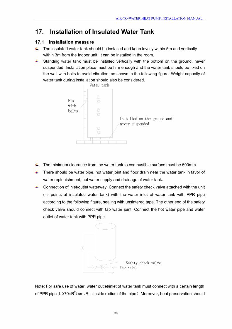
17. Installation of Insulated Water Tank 17.1 Installation measure
The insulated water tank should be installed and keep levelly within 5m and vertically within 3m from the Indoor unit. It can be installed in the room.
Standing water tank must be installed vertically with the bottom on the ground, never suspended. Installation place must be firm enough and the water tank should be fixed on the wall with bolts to avoid vibration, as shown in the following figure. Weight capacity of water tank during installation should also be considered.
The minimum clearance from the water tank to combustible surface must be 500mm.
There should be water pipe, hot water joint and floor drain near the water tank in favor of
water replenishment, hot water supply and drainage of water tank.
Connection of inlet/outlet waterway: Connect the safety check valve attached with the unit
(→ points at insulated water tank) with the water inlet of water tank with PPR pipe
according to the following figure, sealing with unsintered tape. The other end of the safety
check valve should connect with tap water joint. Connect the hot water pipe and water
outlet of water tank with PPR pipe.
Tap waterSafety check valve
Note: For safe use of water, water outlet/inlet of water tank must connect with a certain length
of PPR pipe ,L ≥70×R2(cm,R is inside radius of the pipe). Moreover, heat preservation should
Fix with bolts
Water tank
Installed on the ground and never suspended
35

AIR-TO-WATER HEAT PUMP INSTALLATION MANUAL
be conducted and metal pipe can not be used. For the first use, water tank must be full of
water before the power is on.
17.2 Outline dimension and parameter of water tank
SXVD200LCJ/A-K SXVD200LCJ2/A-K SXVD300LCJ/A-K SXVD300LCJ2/A-K SXVD200LCJ/A-M SXVD200LCJ2/A-M SXVD300LCJ/A-M SXVD300LCJ2/A-M
Litre 200L 200L 300L 300L coil
specification SUS304 Ф22X0.8
M \ 10m \ 10m coil length N 13m 13m 18.5m 18.5m
D(mm) 540 620 D1(mm) 438 528 H(mm) 1595 1620 A(mm) 272 280 B(mm) 105 C(mm) 112 E(mm) 432 464 F(mm) 431 399 I(mm) \ 80 \ 95 J(mm) \ 247.5 \ 202.5 K(mm) 739 718 Outline
(Diameter×H) (mm)
Φ540X1595 Φ620X1620
Package (W*D*H) (mm) 1620X625X630 1645X705X710
Net weight kg 68 71 82 87
Gross weight kg 77 80 92 97
36

AIR-TO-WATER HEAT PUMP INSTALLATION MANUAL
17.3 Connection of Waterway System
If connection between water tank and indoor unit should be through the wall, drill a holeφ70 for pass of circulating water pipe. It is unnecessary if the hole is not needed.
Preparation of pipelines: Circulating water outlet/inlet pipe must be hot water pipe, PPR pipe with nominal out diameter of dn25 and S2.5 series (wall thickness of 4.2mm) being recommended. Cooling water inlet pipe and hot water outlet pipe of water tank should also be hot water pipe, PPR pipe with nominal out diameter of dn20 and S2.5 series (wall thickness of 3.4mm) being recommended. If other insulated pipes are adopted, refer to the above dimensions for out diameter and wall thickness.
Installation of circulating water inlet/outlet pipes: Connect the water inlet of unit with circulating outlet of water tank and water outlet of unit with circulating inlet of water tank.
Installation of water inlet/outlet pipes of water tank: Safety check valve (→ on the valve body points at water tank), filter and cut-off valve must be installed for water inlet pipe according to the installation sketch of unit. At least a cut-off valve is needed for the water outlet pipe.
Installation of blow-off pipe at the bottom of water tank: Connect a piece of PPR pipe with drainage outlet to floor drain. A cut-off valve must be installed in the middle of the drainage pipe and at the place where it is easy to be operated by the users.
After connection of all waterway pipelines, perform leakage test firstly (refer to debugging of the unit). After that, bind up the water pipes, water temp sensor and wires with wrapping tapes attached with the unit.
Refer to Installation Sketch of Unit for details.
temp sensor 2
Blow-off Outlet
Cut-off Valve
Tap water
FilterSafety check valve
Hot water output
Water Tank
Temp Sensor 1
Indoor Unit
Cool Water Inlet
Power cord of booster heater
OtherThermal System
Other Thermal sensor (less than 5 meters)
Joints Dimension Description Joint pipe thread
Hot water outlet of water tank 1/2″Female BSP Circulating water inlet/outlet of water tank 3/4″Female BSP
Cooling water inlet of water tank 1/2″Female BSP Pipe joint 3/4″Female BSP
37

AIR-TO-WATER HEAT PUMP INSTALLATION MANUAL
Joints Dimension Description Joint pipe thread
Circulating water inlet/outlet of main unit 1″Male BSP
Cooling water inlet of water tank 1/2″Female BSP
Circulating water inlet/outlet of water tank 3/4″Female BSP
Hot water outlet of water tank 1/2″Female BSP
Note:
Distance between indoor unit and water tank should not exceed 5m levelly and 3m vertically. If higher, please contact with us. Water tank on lower and main unit on higher side is recommended.
Prepare the materials according to the above joints dimension. If cut-off valve is installed outside the room, PPR pipe is recommended to avoid freeze damage.
Waterway pipelines can’t be installed until water heater unit is fixed. Do not let dust and other sundries enter into pipeline system during installation of connection pipes.
After connection of all waterway pipelines, perform leakage test firstly. After that, perform heat preservation of waterway system; meanwhile, pay more attention to valves and pipe joints. Ensure enough thickness of insulated cotton. If necessary, install heating device for pipeline to prevent the pipeline from freezing.
Hot water supplied from insulated water tank depends on pressure of water tap, so there must be supply of tap water.
During using, the cut-off valve of cooling water inlet of water tank should be kept normally on.
17.4 ELECTRIC WIRING WORK
17.4.1 Wiring Principle General principles
Wires, equipment and connectors supplied for use on the site must be in compliance with provisions of regulations and engineering requirements.
Only electricians holding qualification are allowed to perform wire connection on the site.
Before connection work is started, the power supply must be shut off. Installer shall be responsible for any damage due to incorrect connection of the
external circuit of the unit. Caution --- MUST use copper wires.
Connection of power cable to the electric cabinet of the unit Power cables should be laid out through cabling trough, conduit tube or cable
channel. Power cables to be connected into the electric cabinet must be protected with rubber
or plastic to prevent scratch by edge of metal plate. Power cables close to the electric cabinet of the unit must be fixed reliably to make
the power terminal in the cabinet free from an external force.
38

AIR-TO-WATER HEAT PUMP INSTALLATION MANUAL
Power cable must be grounded reliably.
17.4.2 Specification of Power Supply Wire and Leakage Switch Power cable specifications and Leakage switch types in the following list are recommended for selection.
Power Supply Leakage Switch
Minimum Sectional Area of Earth Wire
Minimum Sectional Area of Power Supply Wire
Model
V Ph Hz (A) (mm2) (mm2) GSH-60IRA 32 6 3×6 GSH-80IRA 50 10 3×10
50 10 3×10 50 10 3×10 50 10 3×10 50 10 3×10 32 6 3×6 32 6 3×6 32 6 3×6 40 10 3×10 40 10 3×10
220~240V-Ph-50Hz
40 10 3×10 16 2.5 5×2.5 16 2.5 5×2.5 16 2.5 5×2.5 25 4.0 5×4.0 25 4.0 5×4.0
380~415V-3Ph-50Hz
25 4.0 5×4.0
Note: Ⅰ、Power cables are copper core cable and copper connectors must be used for power cable
connection. Ⅱ、Leakage Switch is necessary for additional installation. If circuit breakers with leakage
protection are in use, action response time must be less than 0.1 second, leakage circuit must be 30mA.
Ⅲ、The above selected power cable diameters are determined based on assumption of distance from the distribution cabinet to the unit less than 75m. If cables are laid out in a distance of 75m to 150m, diameter of power cable must be increased to a further grade.
Ⅳ、Indoor/outdoor supply cable should be H05RN-F or above. Ⅴ、The power supply must be of rated voltage of the unit and special electrical line for
air-conditioning. Ⅵ、All electrical installation shall be carried out by professional technicians in accordance with
the local laws and regulations. Ⅶ、Ensure safe grounding and the grounding wire shall be connected with the special
grounding equipment of the building and must be installed by professional technicians.
GSH-100IRAGSH-120IRA
GSH-140IRAGSH-160IRA GSH-60ERAGSH-80ERA
GSH-100ERAGSH-120ERA
GSH-140ERAGSH-160ERA
GSH-120IRA-3
GSH-140IRA-3GSH-160IRAGSH-120ERA-3
GSH-140ERA-3GSH-160ERA-3
-3
39

AIR-TO-WATER HEAT PUMP INSTALLATION MANUAL
18. Wring Diagram 18.1 PCB OUTLINE 18.1.1
silk screen Specification
AC-L live wire input of power supply, red N zero wire input of power supply, white
E1 ground wire, yellow green
L2-2 PFC blue inductive wire
L1-1 PFC brown inductive wire L2-1 PFC yellow inductive wire
L1-2 PFC white inductive wire
U U-phase of compressor
V V-phase of compressor
W W-phase of compressor
DC_MOTOR1 DC fan 1 pin:strong power supply;3 pin:fan GND;4 pin:+15V;5 pin:control signal;6 pin:feedback signal;
4V 4V1 4-way valve
HEAT electric heating tape
VA-1 e-heater of chassis
HPP high pressure switch
LPP low pressure switch
OVC-COMP overload protection of compressor
T-SENSOR2 1, 2 hole:pipe temperature;3, 4 hole:environment;5, 6 hole:exhaust T-SENSOR3 1 hole: +3.3V 2 hole: detection ; suction temperature sensor
GSH-60ERA, GSH-80ERA,GSH-100ERA
40
AIR-TO-WATER HEAT PUMP INSTALLATION MANUAL
CN66、CN67 communication cable 2 pin B,3pinA
CN65 communication cable: 1 pin earthed,2 pin B,3 pin A,4 pin+12power supply; It can not be used for communication between outdoor unit and indoor unit;
FA pipe electric expansion valve 1-4 pin:driving impulse output;5 pin:+12V;
H-PRESS signal input of pressure sensor 1 pin:GND;2 pin:signal input;3 pin:+5V
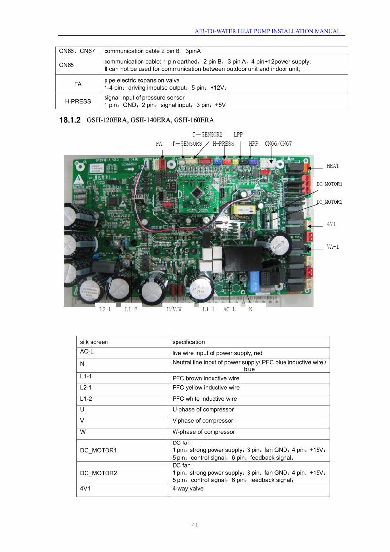
18.1.2
silk screen specification AC-L live wire input of power supply, red
N Neutral line input of power supply(PFC blue inductive wire) blue
L1-1 PFC brown inductive wire L2-1 PFC yellow inductive wire
L1-2 PFC white inductive wire
U U-phase of compressor
V V-phase of compressor
W W-phase of compressor
DC_MOTOR1 DC fan 1 pin:strong power supply;3 pin:fan GND;4 pin:+15V;5 pin:control signal;6 pin:feedback signal;
DC_MOTOR2 DC fan 1 pin:strong power supply;3 pin:fan GND;4 pin:+15V;5 pin:control signal;6 pin:feedback signal;
4V1 4-way valve
GSH-120ERA, GSH-140ERA, GSH-160ERA
41

AIR-TO-WATER HEAT PUMP INSTALLATION MANUAL
HEAT electric heating tape
VA-1 e-heater of chassis HPP high pressure switch
LPP low pressure switch
T-SENSOR2 1, 2hole:pipe temperature;3, 4hole:environment;5, 6hole:exhaust
T-SENSOR3 1 hole:+3.3V 2 hole: detection: suction temperature sensor
CN66、CN67 communication cable 2 pin B,3 pin A
CN65
communication cable 1 pin earthed,2 pin B,3 pin A,4 pin+12 power supply It can not be used for communication between outdoor unit and indoor unit.
FA pipe electric expansion valve
1-4 pin:driving impulse output;5 pin:+12V;
H-PRESS signal input of pressure sensor
1 pin:GND;2 pin:signal input;3 pin:+5V
18.1.3
silk screen specification L1
L2
L3 live wire input of power supply
N Neutral line input of power supply L Reactor red inductive wire U U-phase of compressor
V V-phase of compressor
W W-phase of compressor
GSH-120ERA-3, GSH-140ERA-3, GSH-160ERA-3
42

AIR-TO-WATER HEAT PUMP INSTALLATION MANUAL
DC_MOTOR1 DC fan 1 pin:strong power supply;3 pin:fan GND;4 pin:+15V;5 pin:control signal;6 pin:feedback signal;
DC_MOTOR2 DC fan 1 pin:strong power supply;3 pin:fan GND;4 pin:+15V;5 pin:control signal;6 pin:feedback signal;
4V1 4-way valve
HEAT electric heating tape
VA-1 e-heater of chassis HPP high pressure switch
LPP low pressure switch
T-SENSOR2 1, 2hole:pipe temperature;3, 4hole:environment;5, 6hole:exhaust
T-SENSOR3 1 hole:+3.3V 2 hole: detection: suction temperature sensor
CN66、CN67 communication cable 2 pin B,3 pin A
CN65
communication cable 1 pin earthed,2 pin B,3 pin A,4 pin+12 power supply It can not be used for communication between outdoor unit and indoor unit.
FA pipe electric expansion valve
1-4 pin:driving impulse output;5 pin:+12V;
H-PRESS signal input of pressure sensor
1 pin:GND;2 pin:signal input;3 pin:+5V
18.1.4
AC_L NPUMP1
PUMP2RUN
HEAT3-L
HEAT1-L
HEAT2-L
ERR
2V1_OFF
2V1_ON
2V2_OFF
2V2_ON
3V1_OFF
3V1_ON
3V2_OFF
3V2_ON
T-SENSOR1
DOOR-COVC-HEAT3OVC-HEAT1
OVC-HEAT2IN-SW
COM-MANUAL
COM-OUT
COM-BMSTR-OUT1 TR-OUT2
CN30
CN31
TR-IN
T-SENSOR2T-SENSOR3
T-SENSOR4
T-SENSOR5
LED1
LED2
LED3
T-SENSOR6
GSH-60IRA, GSH-80IRA, GSH-100IRA, GSH-120IRA, GSH-140IRA, GSH-160IRA,GSH-120IRA-3, GSH-140IRA-3, GSH-160IRA-3
43

AIR-TO-WATER HEAT PUMP INSTALLATION MANUAL
silk screen location specification AC-L - live wire of power supply N - Neutral wire of power supply PUMP1 X13 live wire of indoor water pump PUMP2 X14 live wire of solar water pump RUN X15 running indicator HEAT3-L X16 e-heater of water tank HEAT1-L X17 e-heater of indoor unit 1 HEAT2-L X18 e-heater of indoor unit 2 ERR X19 error indicator 2V1_OFF X5 Electric magnetic 2-way valve1 is normally closed. 2V1_ON X6 Electric magnetic 2-way valve1 is normally open. 2V2_OFF X7 Electric magnetic 2-way valve2 is normally closed. 2V2_ON X8 Electric magnetic 2-way valve2 is normally open. 3V1_OFF X9 Electric magnetic 3-way valve1 is normally closed. 3V1_ON X10 Electric magnetic 3-way valve1 is normally open. 3V2_OFF X11 Electric magnetic 3-way valve2 is normally closed. 3V2_ON X12 Electric magnetic 3-way valve2 is normally open. T-SENSOR1 CN10 terminal of temperature sensor1 T-SENSOR2 CN11 terminal of temperature sensor2 T-SENSOR3 CN12 terminal of temperature sensor3 T-SENSOR4 CN13 terminal of temperature sensor4 T-SENSOR5 CN14 terminal of temperature sensor5 T-SENSOR6 CN15 terminal of temperature sensor6 DOOR-C CN23 Door detection input OVC-HEAT3 CN28 e-heater of water tank adhesion-proof protection detector OVC-HEAT1 CN26 e-heater of indoor unit1 adhesion-proof protection detectorOVC-HEAT2 CN27 e-heater of indoor unit2 adhesion-proof protection detectorIN-SW CN25 detection input of water flow switch COM-MANUAL CN6 connect the wired controller COM-OUT CN5 connect to outdoor unit COM-BMS CN7 connect to remote controller TR-OUT1 CN2 transformer output 1 TR-OUT2 CN3 transformer output 2 TR-IN CN1 220V in put of transformer CN30 CN30 heavy-current interface of end controller CN31 CN31 heavy-current interface of end controller
18.2 ELECTRIC WIRING WORK
18.2.1 Wiring Principle
① General principles Wires, equipment and connectors supplied for use on the site must be in compliance with
provisions of regulations and engineering requirements. Only electricians holding qualification are allowed to perform wire connection on the site. Before connection work is started, the power supply must be shut off. Installer shall be responsible for any damage due to incorrect connection of the external
circuit of the unit. Caution --- MUST use copper wires.
②Connection of power cable to the electric cabinet of the unit Power cables should be laid out through cabling trough, conduit tube or cable channel. Power cables to be connected into the electric cabinet must be protected with rubber or
plastic to prevent scratch by edge of metal plate. Power cables close to the electric cabinet of the unit must be fixed reliably to make the
power terminal in the cabinet free from an external force. Power cable must be grounded reliably.
44

AIR-TO-WATER HEAT PUMP INSTALLATION MANUAL
18.2.2 Electric Wiring Design 18.2.2.1 Wiring Diagram: Indoor Unit
XT2XT2 1920
Gate-controller
50
20 19
2 The wires in the imaninal frames are connected by the consumer.
3 power supply for Thermostat:If it is 230V AC,please connect Terminal block(xt3) 21.22.23.24;If it is 24V AC, please connect Terminal block(xt3) 25.26.27.28.
1
N
POWER
AP
XT1
NL
1N(2) 2-way
valve1
2-way valve2
3-way valve1
3-way valve2
Indoor Unit
Long-distance Monitor PC
PC
Specification:1 If there is gate control function, pull out the leading wire 50 on terminal boards between19 and 20 and then connect the Gate-controller
Display board
Communication line
Error indicating lamp
Running indicating lamp
PE PE
PEPE
2. The wires in broken line should be connected by the client.
3 Power supply for thermostat: If it is 230V AC,please connect the thermostat to the terminal block(xt3) 21.22.23.24;If it is 24V AC, please connect the termostat to the terminal block(xt3) 25.26.27.28.
Specification:1. If the gate control function is required, pull out the leading wire 50 between terminal 19 and 20 on the terminal block and then install the gate-controller.
1920
50
20 19XT2 XT2
XT3
XT1POWER
AP
2-way valve1
2-way valve2
3-way valve1
3-way valve2
OUTDOORUNIT AP1
Indoor Unit
PCLong-distance Monitor PC
Display board
Communication line
Error indicating lamp
Running indicating lamp
GSH-60IRA, GSH-80IRA, GSH-100IRA, GSH-120IRA,
GSH-140IRA , GSH-160IRA
GSH-120IRA-3, GSH-140IRA-3, GSH-160IRA-3
45

AIR-TO-WATER HEAT PUMP INSTALLATION MANUAL
18.2.2.2 Wiring Diagram: Outdoor Unit
GSH-60ERA GSH-80ERA, GSH-100ERA
GSH-120ERA, GSH-140ERA , GSH-160ERA
46

AIR-TO-WATER HEAT PUMP INSTALLATION MANUAL
GSH-120ERA-3, GSH-140ERA-3, GSH-160ERA-3,
47

AIR-TO-WATER HEAT PUMP INSTALLATION MANUAL
18.2.2.3 Wiring Diagram: Indoor AND Outdoor Unit(Including Field Wiring) GSH-60IRA/ERA, GSH-80IRA/ERA,GSH-100IRA/ERA, GSH-12IRA/ERA,GSH-140IRA/ERA, GSH-160IRA/ERA
Error indicating lamp
Running indicating lamp
XT2
Insi
de U
nit
Ele
ctric
Box
LN
1N
(2)
XT1
Wat
er ta
nk
LN
LK PO
WE
R
230V
50
HZ
Dis
play
bo
ard
CN
16C
N5
AP
2-w
ay
valv
e12-
way
va
lve2
3-w
ay
valv
e13-
way
va
lve2
Water-tank temp sensor2
Water-tank temp sensor1
Out
door
U
nit
PE
Mai
n B
aord
CN
14
Rem
ote
air
tem
p se
nsor
Long
-dis
tanc
e m
onito
r PC
CN
7Other thermal system Water- out temp sensor
PE
Ther
mos
tat
Ther
mos
tat
Pow
er s
uppl
y fo
r The
rmos
tat:I
f it i
s 23
0V A
C,p
leas
e co
nnec
t Ter
min
al b
lock
(xt3
) 21.
22.2
3.24
;If it
is 2
4V
AC
, ple
ase
conn
ect T
erm
inal
blo
ck(x
t3) 2
5.26
.27.
28.
They
are
can
not
be
conn
ecte
d as
the
sam
e tim
e.
If there is gate cont
rol function,
pull out the
leading wire 50 o
n
terminal board
XT2)between19 and
20 and then conn
ect the Gate-contro
ller
Gat
e-co
ntro
ller
2019
Spe
cific
atio
n:1
Run
ning
indi
catin
g la
mp(
HL1
) and
Err
or in
dica
ting
lam
p (H
L2)
are
conn
ecte
d o
r not
on
the
basi
s of
the
cl
ient
s'de
man
d.2
Clie
nt w
ater
pum
p A
C c
onta
ctor
(KM
4) is
bac
k-up
Pum
p fo
r the
futu
re ,
so it
is
not b
e co
nnec
t;3
Leak
age
Sw
itch(
LK)
is n
eces
sary
for a
dditi
onal
inst
alla
tion,
Ple
ase
refe
renc
e to
pag
e 37
17.
4.2
Spe
cific
atio
n of
Pow
er S
uppl
y W
ire a
nd L
eaka
ge S
witc
h.
48

AIR-TO-WATER HEAT PUMP INSTALLATION MANUAL
Error indicating lamp
Running indicating lamp
XT2
Insi
de U
nit
Ele
ctric
Box
L1N
XT1
Wat
er ta
nk
LK
PO
WER
380
415V
-3P
h-50
Hz
Dis
play
bo
ard
CN
16C
N5
AP
2-w
ay
valv
e12-
way
va
lve2
3-w
ay
valv
e13-
way
va
lve2
Water-tank temp sensor2
Water-tank temp sensor1
Out
door
U
nit
PE
Mai
n B
aord
CN
14
Rem
ote
air
tem
p se
nsor
Long
-dis
tanc
e m
onito
r PC
CN
7
Other thermal system Water- out temp sensorPE
Ther
mos
tat
Ther
mos
tat
Pow
er s
uppl
y fo
r The
rmos
tat:I
f it i
s 23
0V A
C,p
leas
e co
nnec
t Ter
min
al b
lock
(xt3
) 21.
22.2
3.24
;If it
is 2
4V
AC
, ple
ase
conn
ect T
erm
inal
blo
ck(x
t3) 2
5.26
.27.
28.
They
are
can
not
be
conn
ecte
d as
the
sam
e tim
e.
If t
here
is g
ate
cont
rol fun
ctio
n,
pull
out
the
leadi
ng w
ire
50 on
term
inal
board
XT2)bet
ween
19 a
nd
20
and
then
conn
ect
the
Gate-c
ontr
olle
r
Gat
e-co
ntro
ller
2019
Spe
cific
atio
n:1
Run
ning
indi
catin
g la
mp(
HL1
) and
Err
or in
dica
ting
lam
p (H
L2)
are
conn
ecte
d o
r not
on
the
basi
s of
the
cl
ient
s'de
man
d.2
Clie
nt w
ater
pum
p A
C c
onta
ctor
(KM
4) is
bac
k-up
Pum
p fo
r the
futu
re ,
so it
is
not b
e co
nnec
t;3
Leak
age
Sw
itch (
LK)
is n
eces
sary
for a
dditi
onal
inst
alla
tion,
Ple
ase
refe
renc
e to
pag
e 37
17.
4.2
Spe
cific
atio
n of
Pow
er S
uppl
y W
ire a
nd L
eaka
ge S
witc
h.
L2L3
L1L2
L3N
2930
31X
T2
BKB
NB
UY
EGN
PE
GSH-12IRA/ERA-3,GSH-140IRA/ERA-3, GSH-160IRA/ERA-3
49

AIR-TO-WATER HEAT PUMP INSTALLATION MANUAL
18.2.2.4 Terminal Board Information
1 2 3 4 5 6 7 8 9 10 11 12 13 14 15 16 17 18 19 20
Terminal Board 1
power supply for Watertank electric heater
N(2)1NLConnecting external electric power supply for Indoor Unit
Terminal Board 2
Terminal board 3
27 28232221
Thermostat(1) Thermostat(2)
24 25 26
654
2 way value(2)2 way value(1)
1 2 3 987
3 way value(1) 3 way value(2)
10 11 12 151413 16 17 18 19 20
Connection for Client water's AC contactor
Connection for Indicating lihgt
Connection for Accident lihgt
Gate Control Fuction
GSH-60IRA/ERA, GSH-80IRA/ERA,GSH-100IRA/ERA, GSH-12IRA/ERA,GSH-140IRA/ERA, GSH-160IRA/ERA
50

AIR-TO-WATER HEAT PUMP INSTALLATION MANUAL
Terminal Board 1
NL1 L2 L3
Connecting external electric power supply for Indoor Unit
Terminal Board 2
Terminal board 3
27 28232221
Thermostat(1) Thermostat(2)
24 25 26 29 30 31
power supply for water tank eletric heater
654
2 way value(2)2 way value(1)
1 2 3 987
3 way value(1) 3 way value(2)
10 11 12 151413 16 17 18 19 20
Connection for Client water's AC contactor
Connection for Indicating lihgt
Connection for Accident lihgt
Gate Control Fuction
GSH-12IRA/ERA-3,GSH-140IRA/ERA-3, GSH-160IRA/ERA-3
51

AIR-TO-WATER HEAT PUMP INSTALLATION MANUAL
19. Debugging Operation of Unit 19.1 Check before Startup For safety of users and unit, the unit must be started up for check before debugging. The procedures are as below:
The following items shall be performed by qualified repair persons. Confirm together with the sales engineer, dealer, installing contractor and customers forthe following items having been finished or to be finished.
No. Confirmation of Installation √ 1 If the contents of Application for Installation of this Unit by Installer are real. If not,
debugging will be refused. □
2 If there is written notice in which amend project is shown to the installer in respect of unqualified installation. □
3 If Application for Installation of unit by Installer and Debugging list are filed together. □
No. Pre-check √
1 If appearance of the unit and internal pipeline system is ok during conveying, carrying or installation. □
2 Check the accessories attached with the unit for quantity, package and so on. □ 3 Make sure there is drawings in terms of electricity, control, design of pipeline and so on. □
4 Check if installation of the unit is stale enough and there is enough space for operation and repair. □
5 Completely test refrigerant pressure of each unit and perform leakage detection of the unit. □ 6 Check if water tank is installed stably and its bearing is safe upon it is full. □
7 Check if heat insulating measures for the water tank, outlet/inlet pipes and water replenishing pipe are proper. □
8 Check if nilometer of water tank, water temperature indicator, controller, manometer, pressure relief valve and automatic discharge valve etc. are installed and operate properly.
□
9 Check if power supply accords with the nameplate and model of power cord conform to applicable requirements. □
10 Check if power supply and control wiring is connect properly according to wiring diagram, earthing is safe and each terminal is stable. □
11 Check if connection pipe, water pump, manometer, thermometer, valve etc. are installed properly. □
12 Check if each valve in the system is open or closed according to requirements. □ 13 Confirm that the customers and inspection personnel of Part A are at site. □
14 Installation Check-up Table is completed and ask installing contractor’s signature for consent. □
Attention: If the items with ×, please notify the contractor .The above items are recommended. General Evaluation: Debugging □ Amendment □
Judge the following items (if there is not any filling, qualification will be regarded.) a: Power supply and electric control system b Loading calculation c: Heating problems of Unit d: Noise problem e: Pipeline problem f: Others Normal debugging work can’t be performed unless all installation items are qualified. If problem, it must be solved firstly. All costs will be installer’s responsibility for delay of debugging and re-debugging incurred by any problem which is not solved immediately. Submit schedule of amending reports to installer.
Confirm
ed Items after
pre-checking
If provide written amending report to installer which should be signed after communication. Yes () No ()
19.2 Test run
Test run is testing whether the unit can run normally via preoperation. If the unit can not run normally, find and solve the engineering or unit problem until the test run is satisfactory. All
52

AIR-TO-WATER HEAT PUMP INSTALLATION MANUAL
inspection must meet the requirements before performing the test run. Test run should follow the content and steps of the table below: The following procedure should be executed by experience and qualified maintenance man.
No. start up the pretest procedure Notice: before test, ensure that all power must be cut off including far- end power switch. Otherwise, it may cause casualty. 1 Ensure that the compressor of the unit is preheated for 8h. Caution: heat the lubricating oil at least 8h in advance, to prevent the refrigerant from mixing with the lubricating oil, which may cause damage to the compressor when starting up the unit.
2 Check whether the oil temperature of the compressor is obviously higher than the outdoor ambient temperature.
Caution: if the oil temperature of the compressor is obviously higher than the outdoor ambient temperature, it means that the heating tape of compressor is damaged.In that case, the compressor will be damaged easily. Therefore, repair the heating tape Before using the unit.
3 Check whether the phase sequence of main power supply is correct. If not, correct the phase sequence according to specification.
Recheck the phase sequence before start-up to avoid inversion of the compressor which may damage the unit.
4 Apply universal electric meter to measure the insulation resistance between each outdoor phase and earth as well as between phases.
Caution: defective earthing may cause electric shock.
No. Ready to start Cut off all of temporary power supply, resume all the insurance and check the electricity for the last time. 1 Check the power supply and voltage of the control circuit; _____V must be ±10% within the range of rated operating power.
No. Start up the unit
1 Check all the conditions needed to start up the unit: oil temperature, mode, required load ect.
Start up the unit, and observe the operation of compressor, electric expanding valve, fan motor and water pump ect. 2 Note: the unit will be damaged under abnormal running state.
Do not operate the unit in states of high pressure and high current. affixed information:
Estimation or suggestion on the general running situation: good, modify Identify the potential problem( no writing means the installation and debugging are in accordance with the requirements.) a. problem of power supply and electric control system: b. problem of load calculation: c. outdoor refrigerant system: d. noise problem: e. problem of indoor and piping system: h. other problems
During operation, it is needed to charge for the maintenance due to non-quality problems such as incorrect installation and maintenance.
Acceptance situation:
Items for
acceptance after
debugging
Is the user trained according to the specification? Please sign. Yes() No()
53

AIR-TO-WATER HEAT PUMP INSTALLATION MANUAL
20. Daily Operation and Maintenance
In order to avoid damage of unit, all protecting devices in the unit had been set before outgoing, so the user can never adjust or remove them.
For the first startup of the unit or next startup of unit after long-period stop (above 1 day)by cutting off the power, please electrify the unit in advance to preheat the unit for more than 8hr
Never put sundries on the unit and accessories. Keep dry, clean and ventilated around the unit. Remove the dust accumulated on the condenser fin timely to ensure performance of unit and to avoid stop of unit for protection.
In order to avoid protection or damage of unit caused by blockage of water system, clean the filter in water system periodically and frequently check water replenishing device.
In order to ensure anti-freezing protection, never cut off the power if ambient temp. is below zero in winter.
In order to avoid frost crack of the unit, water in the unit and pipeline system not used for a long period should be drained. In addition, open the end cap of water tank for drainage.
Never frequently make the unit on/off and close manual valve of water system during operation of unit by users.
Ensure frequently check the working condition of each part to see if there is oil stain at pipeline joint and charge valve to avoid leakage of refrigerant.
If malfunction of the unit is out of control of users, please timely contact with authorized service center of company.
NOTE:
The water pressure gage is installed in returning water line in the indoor unit,Please
adjust the hydraulics system pressure according to next item:
1. If the pressure is less than 0.5 bar, please recharge the water immediately;
2. when recharging,the hydraulics system pressure should be not more than 2.5Bar.
54

AIR-TO-WATER HEAT PUMP INSTALLATION MANUAL
Troubleshooting
Malfunctions Reasons Troubleshooting
Compressor does not start up
A. Power supply has problem
B. Connection wire is loose.C. Malfunction of mainboardD. Malfunction of
compressor
Phase sequence is reverse Check out and re-fix Find out the reasons and repair. Replace compressor
High noise of fan
A. Fixing bolt of fan is loose B. Fan blade touches shell or
grill C. Operation of fan is
unreliable
Re-fix fixing bolt of fan Find out the reasons and adjust Replace fan
High noise of compressor
A. Liquid slugging happens when liquid refrigerant enters into compressor
B. Internal parts in compressor are broken
Check if expansion valve is failure and temp. sensor is loose .If that, repair it.
Replace compressor
Water pump does not run or runs
abnormally
A. Malfunction of power supply or terminal
B. Malfunction of relay C. There is air in water pipe
Find out the reasons and repair Replace relay Evacuate
Compressor starts or stops frequently
A. Poor or excess refrigerantB. Poor circulation of water
system C. Low load
Discharge or add part of refrigerant Water system is blocked or there is air in
it. Check water pump, valve and pipeline. Clean water filter or evacuate
Adjust the load or add accumulating devices.
The unit does not heat although compressor is
running
A. Leakage of refrigerant B. Malfunction of
compressor
Repair by leakage detection and add refrigerant
Replace compressor
Poor efficiency of hot water heating
A. Poor heat insulation of water system B. Poor heat exchange of evaporator C. Poor refrigerant of unit D. Blockage of heat exchanger at water side
Enhance heat insulation efficiency of the system
Check if air in or out of unit is normal and clean evaporator of the unit
Check if refrigerant of unit leaks Clean or replace heat exchanger.
55

AIR-TO-WATER HEAT PUMP INSTALLATION MANUAL
The table of error code
Error code Error description F4 Malfunction of outdoor environment temperature sensor F6 Malfunction of defrost temperature sensor F7 Malfunction of discharge temperature sensor F5 Malfunction of suction temperature sensor EF Malfunction of outdoor fan E5 Overload proection of compressor or malfunction of driver E1 High pressure protection of compressor E3 Low pressure protection of compressor E4 high-temperature protection of discharge C5 Malfunction of indoor capacity switch E6 Communications failure between outdoor and indoor mainboard E6 Communications failure between outdoor mainboard and wired controller E3 Malfunction of refrigerant lack Fc Malfunction of high pressure sensor F9 Malfunction of outlet temperature sensor dH Malfunction of backup outlet temperature sensor F1 Malfunction of liquid pipe temperature sensor inside refrigerant F8 Malfunction of inlet temperature sensor FE Malfunction of the second sanitary water tank temperature sensor FL Malfunction of the first sanitary water tank temperature sensor F3 Malfunction of gas pipe temperature sensor inside refrigerant dF Malfunction of solar outlet temperature sensor F0 Malfunction of remote room temperature sensor Ec Malfunction of water switch E2 Indoor anti-frozen protetion
No display Over temperature of sanitary water tank temperature Ed Over temperature of outlet temperature(No display on the screen)
No display Over temperature of solar outlet temperature EH Malfunction of internal electric heater EH Malfunction of the first internal electric heater connection EH Malfunction of the second internal electric heater connection EH Malfunction of sanitary water tank electric heater connection dU Pull-out of the gate-controller
56

AIR-TO-WATER HEAT PUMP INSTALLATION MANUAL
21. Parameter Lists
21.1 Product Data at Rated Condition AIR TO WATER HEAT PUMP--PERFORMANCE
Model
Heating(floor ) kW 6.2 8.5 10 12 14 16 Capacity1
Cooling(floor ) kW 5.5 9.0 10.5 14 15 15.5 Heating(floor ) kW 1.5 2.1 2.50 2.67 3.33 3.9 Power
Input1 Cooling(floor ) kW 1.6 2.5 3.14 3.68 4.28 4.62 EER1 Cooling(floor ) - 3.4 3.6 3.35 3.8 3.5 3.35 COP1 Heating(floor ) - 4.1 4.0 4.0 4.5 4.2 4.0
Heating(FCU) kW 5.5 8.0 9.0 11.5 13 14 Capacity2 Cooling(FCU) kW 4 6.5 8.0 10 11 11.5 Heating(FCU) kW 1.8 2.65 2.9 3.35 3.88 4.59 Power
Input2 Cooling(FCU) kW 1.53 2.5 3.08 3.45 3.93 4.2 EER2 Cooling(FCU) - 2.6 2.6 2.6 2.9 2.8 2.5 COP2 Heating(FCU) - 3.0 3.0 3.1 3.4 3.35 3.05
Power Supply V/Ph/Hz 220~240/1/50 Type - R410A R410A R410A R410A R410A R410A Refrigerant Charge g 1700 2000 2000 3300 3300 3300
Sanitary water Temperature ℃ 40-80 40-80 40-80 40-80 40-80 40-80 Sound Pressure Level dB(A) 59 59 59 59 59 62
Gas Piping Connection mm 12.7 15.9 15.9 15.9 15.9 15.9 Liquid Piping Connection mm 6.35 9.52 9.52 9.52 9.52 9.52
Unit(W×D× H) mm 921×427
×791 921×427
×791 921×427
×791 950×412 ×1253
950×412×1253
950×412×1253
Dimensions Outdoor unit
Packed unit(W×D
× H) mm 1065×485
×840 1065×485
×840 1065×485
×840 1110×450
×1385 1110×450
×1385 1110×450
×1385
AIR TO WATER HEAT PUMP--PERFORMANCE
Model Heating(floor ) kW 12 14 15
Capacity1
Cooling(floor ) kW 14 15 15.5 Heating(floor ) kW 2.8 3.33 3.9 Power
Input1 Cooling(floor ) kW 3.8 4.28 4.4 EER1 Cooling(floor ) - 3.8 3.5 3.5 COP1 Heating(floor ) - 4.5 4.2 4.0
Heating(FCU) kW 11 12 14 Capacity2 Cooling(FCU) kW 10 10.5 11 Heating(FCU) kW 3.35 3.8 4.2 Power
Input2 Cooling(FCU) kW 3.45 3.6 4 EER2 Cooling(FCU) - 2.9 2.8 2.7 COP2 Heating(FCU) - 3.4 3.35 3.2
Power Supply V/Ph/Hz 380~415/3/50 Type - R410A R410A R410A Refrigerant Charge g 3500 3500 3500
Sanitary water Temperature ℃ 40-80 40-80 40-80 Sound Pressure Level dB(A) 59 59 62
Gas Piping Connection mm 15.9 15.9 15.9 Liquid Piping Connection mm 9.52 9.52 9.52
Unit(W×D× H) mm 950×412×1253 950×412×1253 950×412×1253 Dimensions
Outdoor unit Packed unit(W×D× H) mm 1110×450×1385 1110×450×1385 1110×450×1385
GSH-12IRA/ERA-3 GSH-140IRA/ERA-3
GSH-160IRA/ERA-3
GSH-60IRA/ERA GSH-80IRA/ERA
GSH-100IRA/ERA
GSH-12IRA/ERA GSH-140IRA/ERA GSH-160IRA/ERA
57

AIR-TO-WATER HEAT PUMP INSTALLATION MANUAL
Note: 1 Capacities and power inputs are based on the following conditions: ①.Cooling conditions –
Indoor Water Temperature 23°C/18°C; Outdoor Air Temperature 35°CDB/24°CWB
②.Heating conditions Indoor Water Temperature 30°C/35°C Outdoor Air Temperature 7°CDB/6°CWB
③.Standard piping length 7.5m 2 Capacities and power inputs are based on the following conditions: ①.Cooling conditions
Indoor Water Temperature 12°C/7°C; Outdoor Air Temperature 35°CDB/24°CWB
②.Heating conditions – Indoor Water Temperature 40°C/45°C; Outdoor Air Temperature 7°CDB/6°CWB
③ Standard piping length 7.5m
INDOOR UNIT
Model
Power Supply V/Ph/Hz 220~240/1/50 Rated input (indoor only) W 3200 6200
Liquid side diameter mm (inch) 6.35(1/4) 9.52(3/8)
Gas side diameter mm (inch) 12.7(1/2) 15.9(5/8)
Cooling (FCU) ℃ 7-25 Cooling (Floor ) ℃ 18-25 Heating (FCU) ℃ 25-55(High Temperature Cycle )
Operation Range
(Outflow water temp.) Heating (Floor ) ℃ 25-45(Low Temperature Cycle )
Type - Water-cooled Nr. of speed - 3 Power input W 200
pump
Water flow limit LPM 7.5
Volume Liter 10 Water Pressure
(Max) Bar 3 Expansion Vessel
Water Pressure (Pre) Bar 1
Type - Sheath Material - Stainless Steel
Operation - Automatic Steps - 2
Capacity 3 6 Combination KW 1.5+1.5 3+3
Electric Heater
Power input Φ/V/Hz 1/230/50 Type - Brazed Plate HEX
Main components
Heat Exchanger Quantity - 1
Unit(W×D× H) mm 900×500×324 Dimensions Packed unit(W×D× H) mm 1040×605×380
GSH-60IRA GSH-80IRA GSH-100IRA GSH-12IRA GSH-140IRA GSH-160IRA
58
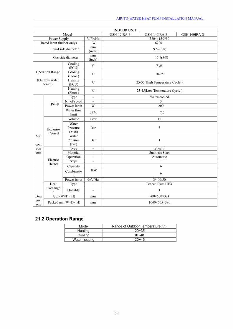
AIR-TO-WATER HEAT PUMP INSTALLATION MANUAL
INDOOR UNIT Model
Power Supply V/Ph/Hz 380~415/3/50 Rated input (indoor only) W 6200
Liquid side diameter mm (inch) 9.52(3/8)
Gas side diameter mm (inch) 15.9(5/8)
Cooling (FCU) ℃ 7-25
Cooling (Floor ) ℃ 18-25
Heating (FCU) ℃ 25-55(High Temperature Cycle )
Operation Range
(Outflow water temp.)
Heating (Floor ) ℃ 25-45(Low Temperature Cycle )
Type - Water-cooled Nr. of speed - 3 Power input W 200
pump
Water flow limit LPM 7.5
Volume Liter 10 Water
Pressure (Max)
Bar 3 Expansion Vessel
Water Pressure
(Pre) Bar 1
Type - Sheath Material - Stainless Steel
Operation - Automatic Steps - 1
Capacity 6 Combinatio
n KW
6
Electric Heater
Power input Φ/V/Hz 3/400/50 Type - Brazed Plate HEX
Main
components
Heat Exchange
r Quantity - 1
Unit(W×D× H) mm 900×500×324 Dimensions Packed unit(W×D× H) mm 1040×605×380
21.2 Operation Range
Mode Range of Outdoor Temperature(℃) Heating -20~35 Cooling 10~48
Water heating -20~45
GSH-12IRA-3 GSH-140IRA-3 GSH-160IRA-3
59


Manufacturer:Sinclair Corporation Ltd., 1-4 Argyll Street,London W1F 7LD, UK
Supplier and technical support:Nepa, spol.s.r.o.Purky ova 45612 00 BrnoCzech Republicwww.nepa.cz
Toll-free info line:+420 800 100 285