air sampling smoke detection system titanus …³n aspiración...air sampling smoke detection system...
TRANSCRIPT


Air Sampling Smoke Detection System
TITANUS SUPER·SENS®
Technical Manual Revision a
WAGNER Group GmbH Schleswigstraße 1 - 5 D-30853 Langenhagen Telephone +49 (0) 511 / 97383-0 Telefax +49 (0) 511 / 97383-140 E-Mail [email protected] Internet www.wagner.de
item number: dated:
supersedes:
69-30-0176 02/09 08/01


Contents TITANUS SUPER·SENS®
TSS_inhalt-en-e Data: 02/09
Contents 0 General 0 – 1
0.1 Introduction 1
0.2 Safety Information 1
0.3 Guarantee 2
0.4 Copyright 2
0.5 Packaging 3
0.6 Disposal 3
1 Product Description 1 – 1
1.1 Characteristics of TITANUS SUPER·SENS® 1
1.2 Areas of Application 3
2 Technical Description 2 – 1
2.1 System Description 1 2.1.1 Function 1 2.1.2 Features 4 2.2 TITANUS® and Accessories 7 2.2.1 Overview 7 2.2.2 Basic device TITANUS® 8 2.2.3 Diagnostic tool DIAG+ 11 2.2.4 Remote display units 15 2.2.5 Device supports 16 2.3 Pipe system 16 2.3.1 Overview of available pipe components 16 2.3.2 Air sampling points for room monitoring 18 2.3.2.1 Aspiration-reducing film sheets 18 2.3.2.2 Air flow reducer clips 19 2.3.3 Ceiling feed-through for hidden installations 21 2.3.4 Air filter for dusty areas 22 2.3.5 Air return for pressurised and dusty areas 23 2.3.6 Noise suppressor 24 2.3.7 Steam trap for humid areas 25
3 Technical Data 3 – 1
3.1 TITANUS® 1
3.2 Accessories – TITANUS® 3
3.3 Pipe system TITANUS® 4

TITANUS SUPER·SENS® Contents
TSS_inhalt-en-e Data: 02/09
Contents 4 Design 4 – 1
4.1 General 1 4.1.1 Regulations 2 4.1.2 Pipe system 3 4.1.3 Air flow monitoring 7 4.1.4 Sensitivity 9 4.1.5 Project planning limits 10 4.2 Project planning 11 4.2.1 Project planning guidelines 11 4.2.1.1 Determining the necessary accessories 11 4.2.2 Pipe accessories 12 4.2.3 Sensitivity and pipeline project planning 13 4.2.3.1 Pipeline project planning with pipe accessories 13 4.2.4 Aperture diameter 17 4.3 Special project planning 20 4.3.1 Project planning for individual aperture monitoring 20 4.3.1.1 I-Pipe system 20 4.3.1.2 U-Pipe system 22 4.3.1.3 M-Pipe system 24 4.3.1.4 Double-U-Pipe system 26 4.3.2 Simplified pipe project planning 28 4.3.2.1 I-pipe system 28 4.3.2.2 U-pipe system 29 4.3.2.3 M-pipe system 30 4.3.2.4 Double U-pipe system 31 4.3.3 Project planning with long intake lines 32 4.3.4 Project planning for forced air flow 33 4.3.4.1 Detection of climatic cabinets with circulating air 33 4.3.4.2 Detection of air conditioning ducts 38 4.4 Mains supply 42
5 Installation of TITANUS® 5 – 1
5.1 General 1
5.2 Opening the TITANUS® air sampling smoke detection system 2
5.3 Settings 3 5.3.1 Base board 3 5.3.1.1 Delay Period of the Air Flow Fault 3 5.3.1.2 Activating Threshold of the Air Flow Monitoring 4 5.3.1.3 Delay Period of the Alarm Activation 4 5.3.1.4 Setting of the Response Sensitivity 5 5.3.1.5 Fault and Alert Alarm Display 6 5.3.1.6 Alarm Thresholds 7 5.3.1.7 Setting of the Ventilator Voltage 7 5.4 Installation of the reset board 9

Contents TITANUS SUPER·SENS®
TSS_inhalt-en-e Data: 02/09
Contents
5.5 Mounting Location 9 5.5.1 Fixing of the air sampling system TITANUS® 9 5.5.2 Connection of the air sampling pipe 11 5.6 Electrical Connection 12 5.6.1 Connection diagram 13 5.6.2 Connection without central fire panel 14 5.6.3 Connection to central fire panel with reset button or
relay contact 15 5.6.4 Connection to central fire panel with reset board 16 5.7 Application of TITANUS® and fire detction system AlgoRex® 17 5.7.1 Collective connection 17 5.7.1.1 Connection diagram collective 18 5.7.2 Application of TITANUS® with AlgoRex® line modules 19 5.7.2.1 Installation of AlgoRex®-line modules in the
TITANUS®- housing 19 5.7.2.2 TITANUS® and AnalogPLUS-Technology 21 5.7.2.3 TITANUS® and interactive Technology 22 5.8 Application TITANUS® and SigmaSys-Technology 23 5.8.1 Mounting of the contact coupler SPF 5300 for the extension 24 5.8.2 Electrical Connection 25 5.9 TITANUS® in the network system 26 5.9.1 Installation network board in TITANUS® 26 5.9.2 Connecting the network module 27 5.10 Remote display units 28 5.10.1 Connection of the remote display unit to TITANUS® 28 5.10.2 Remote display housing design 30 5.10.3 Remote display unit for 19" sub-rack 31 5.10.4 Electrical Connection 32 5.11 Data Log 33
6 Installation of the pipe system 6 – 1
6.1 Linear expansion of the pipe system 4
6.2 Patented air sampling points 6
6.3 Ceiling lead through 8
6.4 Monitoring in forced air flow systems (ventilation or climatic applications) 10
6.4.1 Detection at air inlets/outlets 10 6.4.2 Detection in bypass systems 10 6.5 Filter 11 6.5.1 Installation of air filter, type LF-AD-x 11 6.5.2 Mounting of the special filter type SF-400/650 12

TITANUS SUPER·SENS® Contents
TSS_inhalt-en-e Data: 02/09
Contents
6.6 Air return 13
6.7 Noise suppressor 14
6.8 3-Way ball valve 15
6.8 Steam trap 17
6.9 Test adapter 18
7 Commissioning 7 – 1
7.1 Adjustment air flow sensor 3 7.1.1 Adjustment dependent on the air pressure 3 7.1.2 Adjustment independent of the air pressure 5 7.2 Detector head and alarm transmission 6
7.3 Air Flow Monitoring 6
7.4 Fault signal transmission 7
7.5 Operational check of TITANUS® 8 7.5.1 Preparation of the operational check 8 7.5.2 Operational Check 9
8 Maintenance 8 – 1
8.1 Visual Check 1
8.2 Smoke Detector and Alarm Transmission 1
8.3 Pipe System 1
8.4 Exchange of the Detector Head 2
8.5 Exchange of the air flow sensor filter 4
8.4 Changing the air filter LF-AD –x 5
8.7 Changing special air filter SF-400/650 6
8.8 Check of the Air Flow Sensor Adjustment 7
8.9 Air flow monitoring 8
8.10 Fault signal transmission 8
8.11 Maintenance intervals 8
Contents TITANUS SUPER·SENS®
TSS_inhalt-en-e Data: 02/09
Contents
Appendix
Air Pressure Adjustment Tables
Projection Tables
System Product List
Certificate of Approval of Components and Systems
EMC Declaration of Conformity
Inspection Protocol
Glossary
Conformity certification pursuant to EU

TITANUS SUPER·SENS® Contents
TSS_inhalt-en-e Data: 02/09
TITANUS SUPER·SENS® General
TSS_00_A-en-e Data: 02/09 0 – 1
0 General
0.1 Introduction
This manual is for installers of air sampling smoke detection systems, in particular for engineers, technicians, and fitters etc. who have technical knowledge in the field of smoke detection technology but who are possibly working with this device for the first time.
For damage and faults resulting from the non-observance of this manual WAGNER Group GmbH, called WAGNER in the following, does not assume liability.
This manual refers to the air sampling smoke detection systems TITANUS SUPER·SENS®. These systems may only be used for early and very early smoke detection.
0.2 Safety Information
The following symbols identify parts of the text in this manual which require special attention so that damage can be avoided and so that operations can run smoothly. This symbol warns against actions which might cause damage if it is ignored.
This symbol warns against actions which could cause operational breakdowns if it is ignored.
Operational improvements can be achieved if this symbol is observed.
ATTENTION
INSTRUCTION
TIP

General TITANUS SUPER·SENS®
0 – 2 Data: 02/09 TSS_00_A-en-e
0.3 Guarantee
The manual is subject to technical modification without notice and makes no claim to completeness. In principle our “Terms and Conditions of Supply and Assembly” apply. No claims under the guarantee or for liability can be made for damage to persons or property if they are based on one or more of the following causes: • insufficient observance of the instructions about the design,
assembly of the aspirating smoke detection system, assembly of the pipe system, commissioning and maintenance
• use of the aspirating smoke detection system in contravention of the intended use
• insufficient monitoring of working parts • improperly executed repairs • unauthorised constructional changes to the aspirating smoke
detection system • force majeure
0.4 Copyright
The copyright in this Technical Manual remains with WAGNER. The manual is designed exclusively for the assembler and his colleagues. Reproduction of the manual, including extracts, is not allowed. Copying or distribution of the manual in any form is only allowed with permission in writing from WAGNER.

TITANUS SUPER·SENS® General
TSS_00_A-en-e Data: 02/09 0 – 3
0.5 Packaging
The individual air sampling smoke detection systems are packed in accordance with the anticipated transport conditions. Exclusively environmentally friendly materials were used for the packaging. The packaging is intended to protect the air sampling smoke detection system from being damaged until it is installed. For that reason, it should only be removed from its packaging shortly before installation. The packaging material is to be disposed of in accordance with applicable statutory provisions and local regulations.
Dispose of the packaging materials in an environmentally friendly manner.
Observe local disposal regulations.
Packaging materials are valuable raw materials and in many cases can be re-used or expediently processed and recycled. Improper disposal of packaging materials can harm the environment.
0.6 Disposal
If no take-back or disposal agreements have been made, disassembled components are to be taken for recycling:
Take metal parts for scrapping.
Take plastic parts to be recycled.
Sort the remaining components by material quality and dispose of them.
INSTRUCTION

General TITANUS SUPER·SENS®
0 – 4 Data: 02/09 TSS_00_A-en-e

TITANUS SUPER·SENS® Product Description
TSS_01_A-en-e Data: 02/09 1 – 1
1 Product Description
1.1 Characteristics of TITANUS SUPER·SENS®
TITANUS SUPER · SENS® is the latest generation of the well-proven WAGNER-air sampling smoke detection systems. As highly sensitive device TITANUS SUPER · SENS® reaches a detection quality not known so far. In particular, it can be used for room monitoring in case of high value concentration and to control climatic cabinets or climatic ducts in case of high air exchange rates. TITANUS SUPER·SENS® can even be used in critical areas such as EDP-rooms.
High Sensitivity The device has a display sensitivity of 0.0025%/m light obscuration. According to the application further sensitivities can be set at the base board. Thus, a large detection range throughout all typical standard fire types is possible.
Network System By means of an optional network board several TITANUS SUPER·SENS® can be connected to form a network. Through a central network unit the operator can monitor the whole installation as far as smoke level, air flow values etc. are concerned.
Diagnostic Device The diagnostic device permits a quick and reliable fault localization for maintenance and service. The reading out of the current device state is effected by means of an optical data transmission.
Safe Air Flow Monitoring Like point-type detectors, which are electronically monitored to detect line fractures and short circuits, air sampling systems require a complex and safe air flow monitoring. The unique air flow sensor technology used in all WAGNER-air sampling systems guarantees the detection of faults such as pipe fracture or blockage of single air sampling points.
The air flow monitoring is temperature compensated and can be independent of the air pressure.
Patented Air Sampling Points Depending on the required project planning the air sampling points have
defined drill hole diameters. For these exact air sampling points WAGNER has developed patented aspiration-reducing film sheets with marking tapes and clips that permit an easy mounting and avoid secondary noise e.g. „whistling“.
Temperature Range TITANUS SUPER·SENS® can be operated in a temperature range between -20°C and +60°C. Thus, in contrast to conventional highly sensitive early smoke detection systems operation below 0°C is possible for the first time.
Product Description TITANUS SUPER·SENS®
1 – 2 Data: 02/09 TSS_01_A-en-e
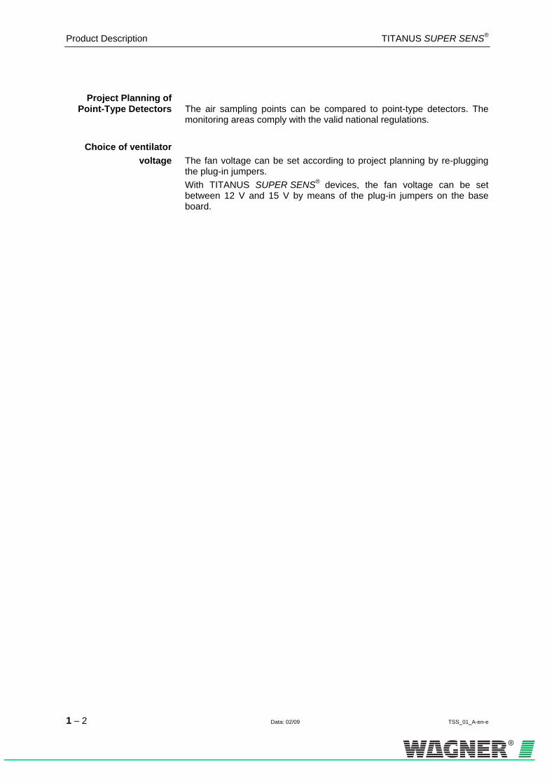
Project Planning of Point-Type Detectors The air sampling points can be compared to point-type detectors. The
monitoring areas comply with the valid national regulations.
Choice of ventilator voltage The fan voltage can be set according to project planning by re-plugging
the plug-in jumpers. With TITANUS SUPER·SENS® devices, the fan voltage can be set between 12 V and 15 V by means of the plug-in jumpers on the base board.
TITANUS SUPER·SENS® Product Description
TSS_01_A-en-e Data: 02/09 1 – 3
1.2 Areas of Application
The air sampling smoke detection system TITANUS SUPER·SENS® is a technology used for early smoke detection and very early smoke detection for rooms and equipment.
Principle Air samples are drawn from the protected area via a pipe system with defined air sampling points and passed to the detector module. It is particularly suitable for areas in which point-type detectors cannot be used or only under certain conditions. In particular these are areas:
• with high fire risk • where a high detection sensibility is required • with limited access and where point-type detectors are difficult to
install or service • which are air conditioned • which have a greater height than admissible for point-type detectors • where point-type detectors are undesirable for aesthetic reasons • where electromagnetic fields have an impact • which are exposed to high or low temperatures • where filters are required due to impurities in the atmosphere • which must be protected from vandalism.

Product Description TITANUS SUPER·SENS®
1 – 4 Data: 02/09 TSS_01_A-en-e
TITANUS® is suitable for:
Room protection Rooms such as:
• floor voids, ceiling voids • tunnels, ducts, voids with difficult access • storage areas, high-rack storage, elevator shafts • museums, cultural centre’s • deep-freeze storage
10987654321
TITANUSSUPER ·SENS®
10987654321
TITANUSSUPER ·SENS®
Fig. 1.1: Sketch: room monitoring with the TITANUS® air-sampling smoke detection system

TITANUS SUPER·SENS® Product Description
TSS_01_A-en-e Data: 02/09 1 – 5
Room monitoring with air conditioning Room monitoring takes place
• in air-conditioned rooms for servicing etc
• in ventilation ducts
• of floor voids, ceiling voids
• in EDP rooms, E-distribution cabinets, transformer cells
• in climatic cabinets (see fig. 1.2) or
• at air conditioning ducts in the by-pass
convection air
conditioningsystem
TITANUS®
climatic duct
TITANUS®
TITANUS®
Fig. 1.2: Sketch: Monitoring possibilities of a convection air conditioning cabinet or air
conditioning duct

Product Description TITANUS SUPER·SENS®
1 – 6 Data: 02/09 TSS_01_A-en-e

TITANUS SUPER·SENS® Technical Description
TSS_02_A-en-e Data: 02/09 2 – 1
2 Technical Description
2.1 System Description
The air sampling smoke detection system TITANUS® consists of the ba-sic device, the pipe system and accessories. The most important components of the basic device are the highly sensi-tive smoke detector to detect the smoke aerosols and the aspiration unit to pass the air samples to the smoke detector as well as the air flow sen-sor in order to monitor the pipe system for fracture and blockage. Essentially, the pipe system consists of pipes and fittings made of PVC or ABS plastic. In order to protect the device many accessories are available as e.g. the air filter and the remote display unit. The remote display unit serves for the display of the state of the basic device during the installation at blind places. Each air sampling point in the pipe system of TITANUS® represents a ceiling detector.
2.1.1 Function
Fig. 2.1: Air sampling system TITANUS®
By means of the aspiration unit in the basic device air samples are drawn from the area to be monitored via a pipe system with defined air sampling points which are then passed to a highly sensitive detector head (refer to 0HFig. 2.1).
Technical Description TITANUS SUPER·SENS®
2 – 2 Data: 02/09 TSS_02_A-en-e
Detector Head If the detector head detects smoke aerosols in the air sample the current smoke level is indicated by TITANUS® through the level display. The three alarm levels alert, action and fire alarm are indicated by LED’s and can be passed to the central fire panel via potential-free contacts. Differ-ent delay periods can be set for the alarm levels. In the event of the de-tector head becoming soiled a drift is effected. The drift complies with the requirements of the valid European standard. The alert alarm can be set to a latched (standard) or non-latched mode. In contrast to this the action alarm and fire alarm are always set to the latched mode. The alarm indications are to be reset after the cause of the fault has been cleared.
Monitoring of the Detector Head The detector head is checked for soiling, signal faults, detaching and volt-
age. A fault is indicated through the fault-LED of TITANUS® and can be passed to the central fire panel via a fault contact.
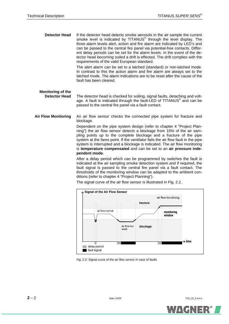
Air Flow Monitoring An air flow sensor checks the connected pipe system for fracture and blockage. Dependent on the pipe system design (refer to chapter 4 "Project Plan-ning") the air flow sensor detects a blockage from 15% of the air sam-pling points up to the complete blockage and a fracture of the pipe system at the fares point. If the ventilator fails the air flow fault in the pipe system is interrupted and a blockage is indicated. The air flow monitoring is temperature compensated and can be set to an air pressure inde-pendent mode. After a delay period which can be programmed by switches the fault is indicated at the air sampling smoke detection system and if required, the fault signal is passed to the central fire panel via a fault contact. The thresholds of the monitoring window can be adapted to the ambient con-ditions (refer to chapter 4 “Project Planning“). The signal curve of the air flow sensor is illustrated in 1HFig. 2.2..
Fig. 2.2: Signal curve of the air flow sensor in case of faults

TITANUS SUPER·SENS® Technical Description
TSS_02_A-en-e Data: 02/09 2 – 3
Fault Display A detector head or air flow fault causes a fault signal which is indicated at TITANUS®. The fault display can be set to a latched (standard mode) or non-latched mode (refer to page 5.5). In case of a standard mode the fault is to be reset by means of a reset button after the cause has been eliminated.
Reset Button In order to reset alarm and fault signals TITANUS® is equipped with con-nectors to which a reset button can be connected.
Reset through Central Fire Panel The reset is easier through a central fire panel. If the TITANUS® is con-
nected to a central fire panel and it is required to reset alarm and fault signals at the device together with the reset of the detection line a reset board 0F
1 is mounted as an option. It automatically resets the alarm and fault signals at TITANUS® in case of a temporary switch-off of the line voltage.
1 The reset board can only be used if the quiescent current of the line is at least 5 mA.
The line has to be current less during reset.
Technical Description TITANUS SUPER·SENS®
2 – 4 Data: 02/09 TSS_02_A-en-e
2.1.2 Features
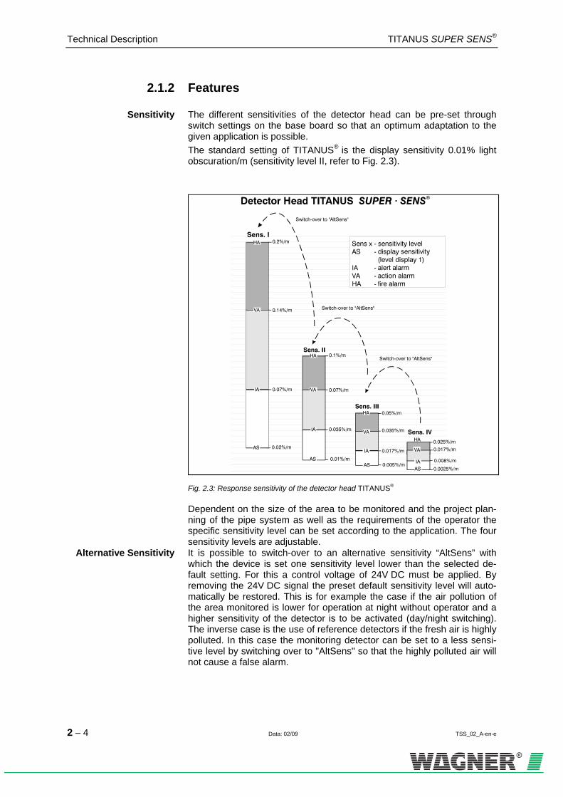
Sensitivity The different sensitivities of the detector head can be pre-set through switch settings on the base board so that an optimum adaptation to the given application is possible. The standard setting of TITANUS® is the display sensitivity 0.01% light obscuration/m (sensitivity level II, refer to 2HFig. 2.3).
Fig. 2.3: Response sensitivity of the detector head TITANUS®
Dependent on the size of the area to be monitored and the project plan-ning of the pipe system as well as the requirements of the operator the specific sensitivity level can be set according to the application. The four sensitivity levels are adjustable.
Alternative Sensitivity It is possible to switch-over to an alternative sensitivity “AltSens” with which the device is set one sensitivity level lower than the selected de-fault setting. For this a control voltage of 24V DC must be applied. By removing the 24V DC signal the preset default sensitivity level will auto-matically be restored. This is for example the case if the air pollution of the area monitored is lower for operation at night without operator and a higher sensitivity of the detector is to be activated (day/night switching). The inverse case is the use of reference detectors if the fresh air is highly polluted. In this case the monitoring detector can be set to a less sensi-tive level by switching over to "AltSens" so that the highly polluted air will not cause a false alarm.

TITANUS SUPER·SENS® Technical Description
TSS_02_A-en-e Data: 02/09 2 – 5
Relay Outputs For each alarm threshold (alert, action, fire alarm) and for the collective
fault TITANUS® has a potential-free switching-over contact. Thus, the air sampling smoke detection system can be connected to collective and addressable 1F
2 detection lines of any central fire panel.
Air Flow Adjustment The air flow of TITANUS® is automatically adjusted. The initialization phase is effected dependently on or independently of the air pressure. Thus, commissioning is much easier. In order to adjust a characteristic air flow of the pipe network the air flow-init process is effected. For each device this process is necessary one time after the installation, after each modification of the pipe system lay-out and after the modification of the ventilator voltage. Thus, the device memorizes the air flow characteristic of the pipe network.
Detector Head Adjustment At each device start (switch-on of the operating voltage) the detector
head is automatically initialized via the device electronics, which perma-nently checks the data delivered by the detector head for faults.
Pipe System A pipe system up to a total length of 200 m with a maximum number of 24 air sampling points can be connected to TITANUS®.
Temperature Range The standard temperature range of TITANUS ® is -20°C up to +60°C.
Diagnostics By means of a diagnostic device, a PC or laptop TITANUS® can be
checked without opening it. Besides the current air flow sensor data and the smoke level values different status values can be read out. Thus, it is easier to detect changed operating conditions for service. Another possi-bility is to receive the data through a pre-fabricated cable (diagnostic-interface) via a PC.
Recorder Outputs For long-time recording of the smoke level and the air flow sensor signals TITANUS® has an analogue line recorder output.
Ventilator Voltage For special project planning’s the air transport speed is increased through switching the ventilator voltage from 12 V to 15 V.
2 Only possible via addressable modules of the corresponding central fire panel.

Technical Description TITANUS SUPER·SENS®
2 – 6 Data: 02/09 TSS_02_A-en-e
Network System The danger management and information system VisuLAN® serves the
state control of all TITANUS® in the network. Thus, the operator in the control room can centrally monitor the whole installation as far as smoke level, air flow values etc. are concerned. Ground plans of the different buildings and floors are included in VisuLAN® and the spatial arrange-ment of the air sampling smoke detection systems is displayed. A diag-nostic window with help texts permits a quick analysis of the causes of the faults. The course of the smoke level and of the air flow values of sin-gle TITANUS® is graphically displayed and can be printed. The state of the alarm and fault relays is also displayed by this graph.

TITANUS SUPER·SENS® Technical Description
TSS_02_A-en-e Data: 02/09 2 – 7
2.2 TITANUS® and Accessories
2.2.1 Overview
TITANUS
front film sheet
®
pipe adapter(option)
air return
reset board (option)
Connections
A
B
central fire panel / power supply
pipe systems
device support(option)
mounting set linemodules (optional)
mounting set SigmaSys(optional)
cable entry(optional)
cable entry(optional)
network board (optional)
connection cablediagnostic
interface
fire detectioncable
blind plug(option)
diagnostic device for TITANUS
remote display unit in wall housing(option)
blind plate(option)
front film sheet for PAG-TITANUS ®
remote display unit 19"(option)
line modules (optional)
Fig. 2.4: Overview TITANUS®
The further components illustrated in 3HFig. 2.4 can be used optionally.

Technical Description TITANUS SUPER·SENS®
2 – 8 Data: 02/09 TSS_02_A-en-e
2.2.2 Basic device TITANUS®
The basic device TITANUS® consists of the following components: plastic housing highly sensitive detector head with the latest technology according to optical scattered light detectors
air sampling unit with air flow monitoring optical displays for "smoke level", "alarm", "fault" and "ON" infrared-LED to read out the current state of the device connector for pipes with an outer diameter of 25 mm plastic connection piece with ferrite rings and insulating hose
Fig. 2.5: Displays and connections of TITANUS ® (explanations in table, page 2-9)
Fig. 2.6: Displays TITANUS ® (explanations number 1 in table, page 2-9)
TITANUS SUPER·SENS® Technical Description
TSS_02_A-en-e Data: 02/09 2 – 9
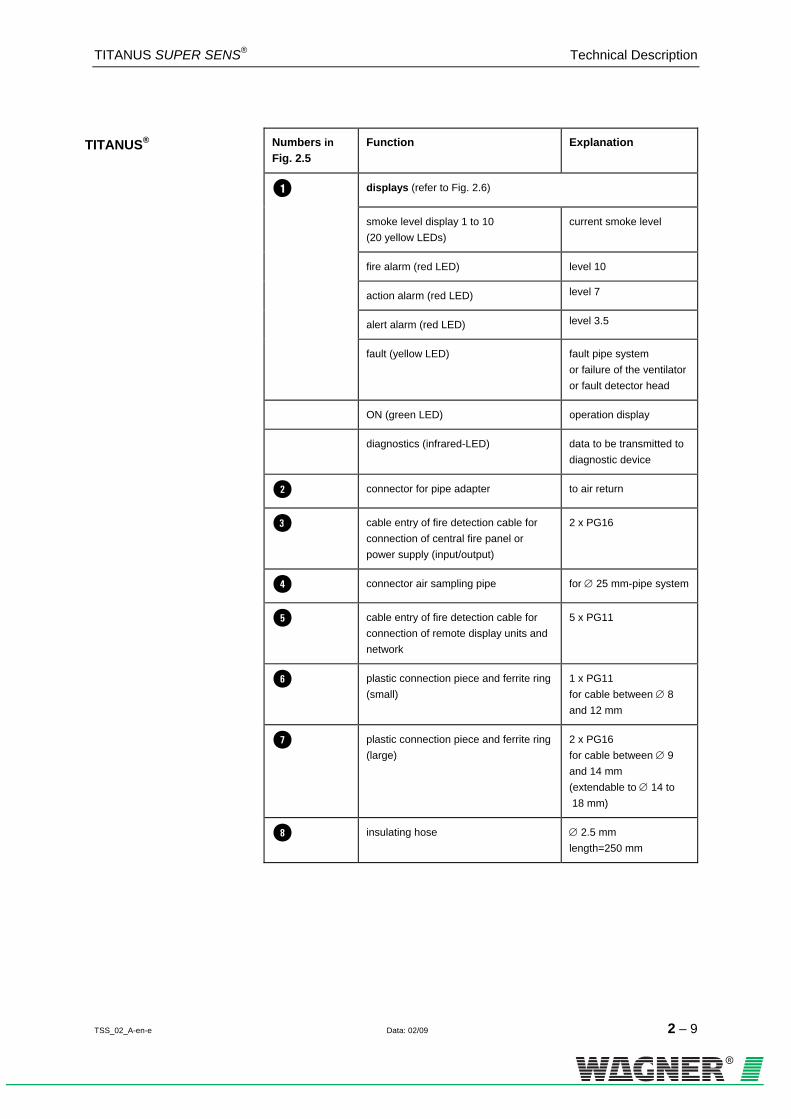
TITANUS® Numbers in 4HFig. 2.5
Function Explanation
displays (refer to 5HFig. 2.6)
smoke level display 1 to 10 (20 yellow LEDs)
current smoke level
fire alarm (red LED) level 10
action alarm (red LED) level 7
alert alarm (red LED) level 3.5
fault (yellow LED) fault pipe system or failure of the ventilatoror fault detector head
ON (green LED) operation display
diagnostics (infrared-LED) data to be transmitted to diagnostic device
connector for pipe adapter to air return
cable entry of fire detection cable for connection of central fire panel or power supply (input/output)
2 x PG16
connector air sampling pipe for ∅ 25 mm-pipe system
cable entry of fire detection cable for connection of remote display units and network
5 x PG11
plastic connection piece and ferrite ring (small)
1 x PG11 for cable between ∅ 8 and 12 mm
plastic connection piece and ferrite ring (large)
2 x PG16 for cable between ∅ 9 and 14 mm (extendable to ∅ 14 to 18 mm)
insulating hose ∅ 2.5 mm length=250 mm

Technical Description TITANUS SUPER·SENS®
2 – 10 Data: 02/09 TSS_02_A-en-e
2.2.3 Diagnostic tool DIAG+
TITANUS SUPER · SENS®
infrared-LED
diagnostic device
battery case
connection cablefor PC
connection cablediagnostic interface(pre-fabricated cable)
DIAG+
3.5"-disks withevaluation software
3.5"-disks withevaluation software
receiving diode
Fig. 2.7: Diagnostic device to read out the state of the device
For maintenance and service the diagnostic device is able to limit the number of faults (refer to 6HFig. 2.7). The current and memorized state of the device is read out through data transmission on optical basis. TITANUS ® has an infrared-LED that continuously sends data. TITANUS® memorizes set faults and resets for at least 96 hours, even if the cause of the fault has already been eliminated. This allows to analyze even shortly, sporadically occurring environmental influences (e.g. changed operating conditions). By means of the diagnostic device the smoke level and the air flow can be recorded. At the bottom side of the diagnostic device there is the receiving diode. In order to receive the data the diagnostic device has to be put on the infra-red-LED of TITANUS®. Via a micro-processor in the diagnostic device the information sent by the air sampling smoke detection system are re-ceived and memorized. Through a serial interface cable the memorized data are directly passed to a PC 2F
3. The data remain in the diagnostic de-vice until another air sampling smoke detection system is analyzed. The evaluation and the display are effected by means of the delivered soft-ware.
3 PC with serial interface (COM1 or COM2) and WINDOWS95

TITANUS SUPER·SENS® Technical Description
TSS_02_A-en-e Data: 02/09 2 – 11
The remote display unit has also an infrared-LED to transmit data to the diagnostic device. Thus, an easy reading out of the data is possible even if TITANUS® is mounted so that it is not readily accessible. Through the central installation of several TITANUS® e.g. in a control room mainte-nance and service costs can be considerably reduced.
For the commissioning of TITANUS® the diagnostic device is not neces-sary. However, it facilitates to log the commissioning data.
As an alternative the connection cable with diagnostic interface (pre-fabricated cable) is used for the direct data transmission to a PC. This is an advantage for long-time tests to analyze the smoke level or the air flow. The connection of the cable is described in chapter 5.13.
TIP
Technical Description TITANUS SUPER·SENS®
2 – 12 Data: 02/09 TSS_02_A-en-e
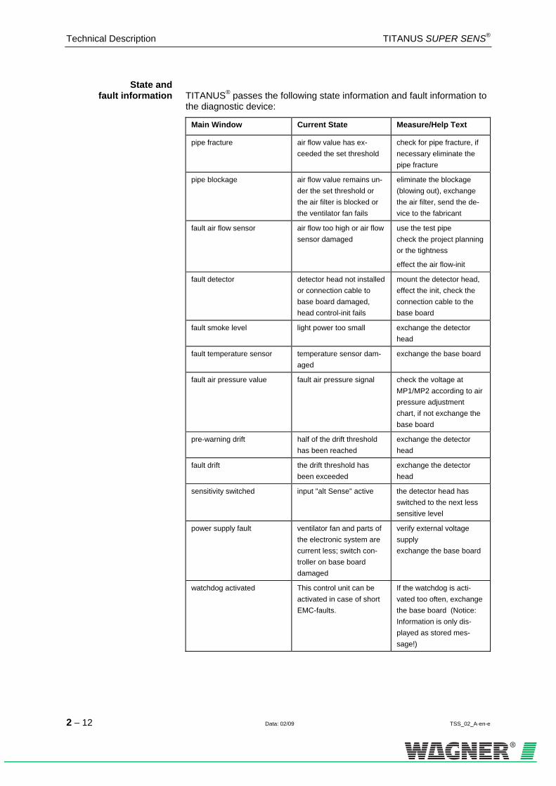
State and fault information TITANUS® passes the following state information and fault information to
the diagnostic device:
Main Window Current State Measure/Help Text
pipe fracture air flow value has ex-ceeded the set threshold
check for pipe fracture, if necessary eliminate the pipe fracture
pipe blockage air flow value remains un-der the set threshold or the air filter is blocked or the ventilator fan fails
eliminate the blockage (blowing out), exchange the air filter, send the de-vice to the fabricant
fault air flow sensor air flow too high or air flow sensor damaged
use the test pipe check the project planning or the tightness
effect the air flow-init
fault detector detector head not installed or connection cable to base board damaged, head control-init fails
mount the detector head, effect the init, check the connection cable to the base board
fault smoke level light power too small exchange the detector head
fault temperature sensor temperature sensor dam-aged
exchange the base board
fault air pressure value fault air pressure signal check the voltage at MP1/MP2 according to air pressure adjustment chart, if not exchange the base board
pre-warning drift half of the drift threshold has been reached
exchange the detector head
fault drift the drift threshold has been exceeded
exchange the detector head
sensitivity switched input "alt Sense" active the detector head has switched to the next less sensitive level
power supply fault ventilator fan and parts of the electronic system are current less; switch con-troller on base board damaged
verify external voltage supply exchange the base board
watchdog activated This control unit can be activated in case of short EMC-faults.
If the watchdog is acti-vated too often, exchange the base board (Notice: Information is only dis-played as stored mes-sage!)

TITANUS SUPER·SENS® Technical Description
TSS_02_A-en-e Data: 02/09 2 – 13
Main Window Current State Measure/Help Text
fault set value storage storage faults initialize the air flow
no set value stored initialize the air flow
power ON reset base board has been set off and on again (Notice: Information only as stored message!)
check the external voltage supply
reset detected processor of base board has activated reset, (No-tice: Information only as stored message!)
A short failure of the ex-ternal voltage supply can activate a reset. Verify voltage supply and cable connections.
Air Flow Menu Help Text pipe 1 Air flow value relative to set threshold: 100% = threshold
exceeded (fault). For the small or medium threshold an adjustment dependent on the air pressure is required. An adjustment independent of the air pressure is only possi-ble for a large or a very large threshold. The following air flow variations are allowed for an ad-justment dependent on the air pressure: • small threshold: ± 90% • medium threshold: ± 50% • large threshold: ± 25% If the air flow value is not within the tolerances the pipe system is to be checked for tightness or blockage of the air sampling points.
Information of the current smoke level is transmitted. This data is only visible during trend recordings (DiagPlus menu „recordings“).
TIP

Technical Description TITANUS SUPER·SENS®
2 – 14 Data: 02/09 TSS_02_A-en-e
2.2.4 Remote display units
remote display unitin wall housingremote display unit
for 19"-subrack
blind plate for 19"-subrack
Fig. 2.8: Remote display unit for 19“-subracks and wall mounting
TITANUS® has connectors for a maximum number of two remote display units per device. The displays of the remote display unit are the same as those of the basic device. The remote display units are connected to the base board of TITANUS®. A remote display unit can be installed in a distance of up to 1000 m. If two remote display units are mounted at the same time the total length of the connection lines must not be longer than 500 m. For small distances the power supply is directly guaranteed by the TITANUS®, for long distances it is guaranteed by an external power sup-ply (refer to chapter 4.8 “Calculation of the Power Supply“). There are two types of remote display units available (refer to 7HFig. 2.8):
Types for the wall mounting in housing for the installation into a 19“-subrack (3 units of height, 21 submultiples of units)
The housing lid of the wall housing type is turn able by 180°, which means that the cable entries can be on the top or on the bottom. Up to 4 remote display units can be mounted in a 19“-subrack. For un-used modules use the corresponding blind plates.
TITANUS SUPER·SENS® Technical Description
TSS_02_A-en-e Data: 02/09 2 – 15
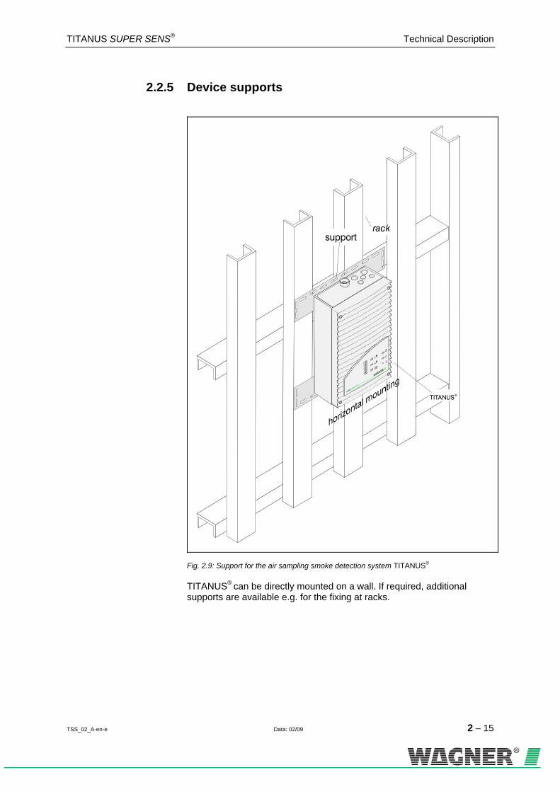
2.2.5 Device supports
TITANUS®
supportrack
Fig. 2.9: Support for the air sampling smoke detection system TITANUS®
TITANUS® can be directly mounted on a wall. If required, additional supports are available e.g. for the fixing at racks.

Technical Description TITANUS SUPER·SENS®
2 – 16 Data: 02/09 TSS_02_B-en-e
2.3 Pipe system
2.3.1 Overview of available pipe components
A
TITAN U S®
A
A
A
A
Co n n ect io n s
A pipe system
special filter
45°- e lbow
steam trap
Air filter
double screw joint
ceiling feed through
air sampling
hose-
reducer coupling
end cap
90° e lbow
90° arc
air sampling pipe
T-piece
sleeve
test adapter
noise suppressor
pipe cap (optional)
marking tape for AFpipe with PG16 internal thread
air flow reduceraspiration reducing film sheet
air return(air sampling pipe)
blind plugtype HSK-V
(optional) pipe adapter(option)
pipe adapter
Fig. 2.10: Components for the pipe system
The components illustrated in Fig. 2.10 are to be chosen according to the given application and can be combined.
TITANUS SUPER·SENS® Technical Description
TSS_02_B-en-e Data: 02/09 2 – 17
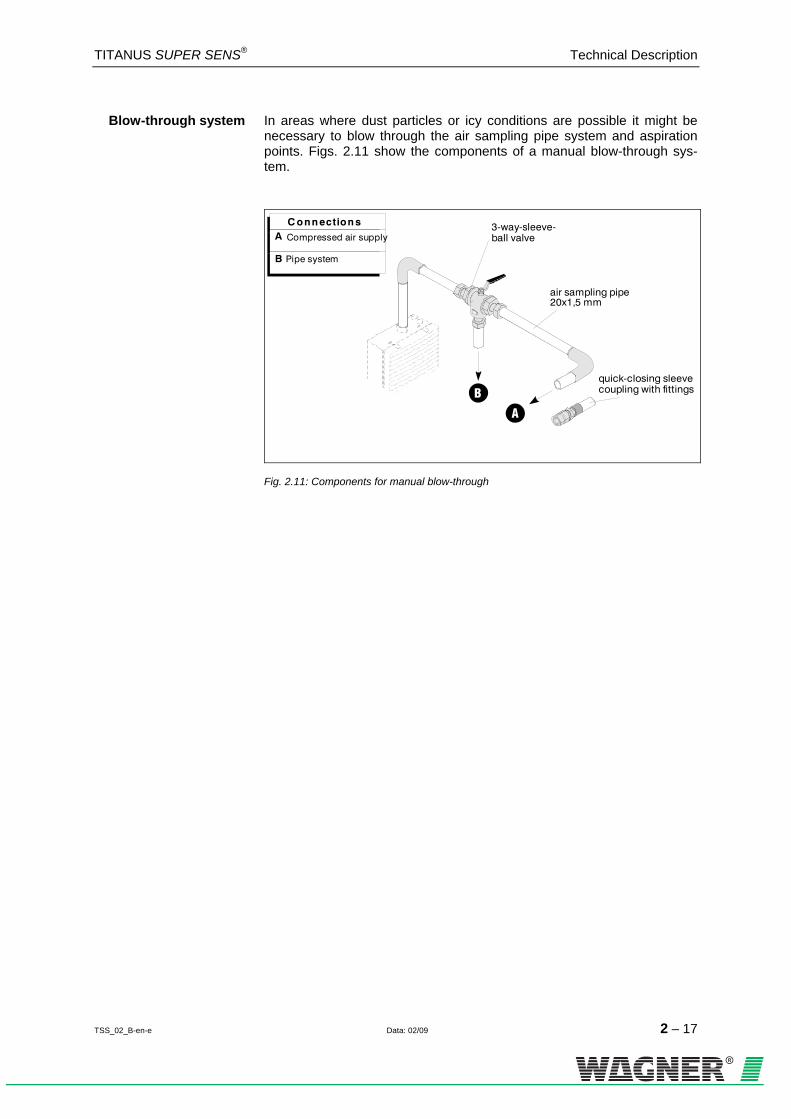
Blow-through system In areas where dust particles or icy conditions are possible it might be necessary to blow through the air sampling pipe system and aspiration points. Figs. 2.11 show the components of a manual blow-through sys-tem.
B
A
C onnection sA
B
Compressed air supply
Pipe system
3-way-sleeve-ball valve
quick-closing sleeve coupling with fittings
air sampling pipe20x1,5 mm
Fig. 2.11: Components for manual blow-through
Technical Description TITANUS SUPER·SENS®
2 – 18 Data: 02/09 TSS_02_B-en-e
2.3.2 Air sampling points for room monitoring
2.3.2.1 Aspiration-reducing film sheets
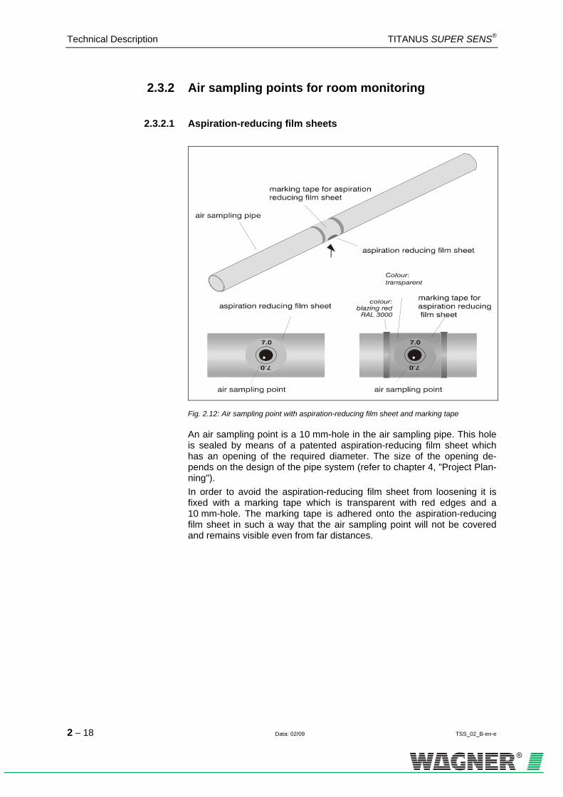
Fig. 2.12: Air sampling point with aspiration-reducing film sheet and marking tape
An air sampling point is a 10 mm-hole in the air sampling pipe. This hole is sealed by means of a patented aspiration-reducing film sheet which has an opening of the required diameter. The size of the opening de-pends on the design of the pipe system (refer to chapter 4, "Project Plan-ning"). In order to avoid the aspiration-reducing film sheet from loosening it is fixed with a marking tape which is transparent with red edges and a 10 mm-hole. The marking tape is adhered onto the aspiration-reducing film sheet in such a way that the air sampling point will not be covered and remains visible even from far distances.

TITANUS SUPER·SENS® Technical Description
TSS_02_B-en-e Data: 02/09 2 – 19
2.3.2.2 Air flow reducer clips
air flow reducer for deep freeze storage areas
plastic clip for air flow reducer
Fig. 2.13: Air flow reducer for dirty areas and deep freeze storage
The air sampling points, when used in areas where blockages can occur, are equipped with a patented plastic clip, type AK-C, and a patented flexi-ble air flow reducer, type AK-x (refer to Fig 2.13). When used in deep freeze areas, the flexible air flow reducer near the air sampling points expands and the ice is blasted off during blow-through. The special plastic clip ensures that the air flow reducer remains in place. The standard aspiration-reducing film sheets, type AF-x, and the marking tapes, type AF-BR, are not suitable for deep freeze storage areas.
For designs in areas requiring a blow-through system (e.g. dusty), air flow reducers with plastic clips are used rather than aspiration-reducing film sheets with marking tapes, because the openings can be blown clear more easily. The plastic clips are more resistant at high pressures and can be cleaned more effectively due to the rubber core.
Technical Description TITANUS SUPER·SENS®
2 – 20 Data: 02/09 TSS_02_B-en-e
2.3.3 Ceiling feed-through for hidden installations
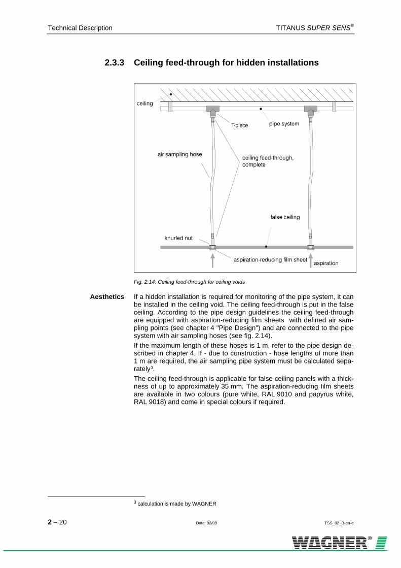
Fig. 2.14: Ceiling feed-through for ceiling voids
Aesthetics If a hidden installation is required for monitoring of the pipe system, it can be installed in the ceiling void. The ceiling feed-through is put in the false ceiling. According to the pipe design guidelines the ceiling feed-through are equipped with aspiration-reducing film sheets with defined air sam-pling points (see chapter 4 "Pipe Design") and are connected to the pipe system with air sampling hoses (see fig. 2.14). If the maximum length of these hoses is 1 m, refer to the pipe design de-scribed in chapter 4. If - due to construction - hose lengths of more than 1 m are required, the air sampling pipe system must be calculated sepa-rately0F
3. The ceiling feed-through is applicable for false ceiling panels with a thick-ness of up to approximately 35 mm. The aspiration-reducing film sheets are available in two colours (pure white, RAL 9010 and papyrus white, RAL 9018) and come in special colours if required.
3 calculation is made by WAGNER

TITANUS SUPER·SENS® Technical Description
TSS_02_B-en-e Data: 02/09 2 – 21
2.3.4 Air filter for dusty areas
Fig. 2.15: TITANUS® with air filter
In highly dusty areas air filters are to be used in order to protect the de-tector head of the device. These soiling can occur e.g. in areas with fresh air supply.
Air Filter Type LF-AD-x As standard air filter the air filter type LF-AD consisting of a plastic hous-ing and two PG29-screw joints are used. The multi-layer filter absorbs particles larger than about 15μm. The air filter is automatically monitored for dirt (blockage) through the air flow monitoring system of the TITANUS SUPER·SENS®. If the air filters are blocked they are blown-out together with the pipe system by means of compressed air. After having opened the filter housing it is easy to ex-change the filter elements if necessary.
Special Filter Type SF-x In case of a high amount of dust a special filter type SF-650 or type SF-400 with a larger surface and a longer service life is available. The spe-cial filter guarantees a safe filtration of dust and dirt. The particles are separated and permanently kept back from the filter medium. Even if the filter is due to be changed a constant air quality is guaranteed.

Technical Description TITANUS SUPER·SENS®
2 – 22 Data: 02/09 TSS_02_B-en-e
2.3.5 Air return for pressurised and dusty areas
Fig. 2.16: Air return with TITANUS®
If the air sampling smoke detection system TITANUS SUPER·SENS® and the pipe system are installed in two areas P1 and P2 with different air pressures the air is to be returned to the pressure area of the pipe system (refer to 0HFig. 2.16). The air return can be used for a pressure compensation or in order to keep the air clean (e.g. from odours) in neigh boring rooms.
TITANUS ®
pipe adapter
screw jointPG29
air return
air sampling pipe
blind plug
Fig. 2.17: TITANUS® with pipe adapter
The return air pipe system is connected to the pipe adapter type RA-AD2 which is mounted onto the air outlets of the TITANUS® (refer to 1HFig. 2.17). The remaining output of the pipe adapter is closed through a blind plug.

TITANUS SUPER·SENS® Technical Description
TSS_02_B-en-e Data: 02/09 2 – 23
2.3.6 Noise suppressor
pipe adapter blind plug
screw jointPG29
TITANUS® noise suppressor
Fig. 2.18: TITANUS® with noise suppressor
By using the SD-1 noise suppressor, the noise level can be reduced by up to 10 db(A) for use in areas in which low noise emissions are required from the TITANUS® (such as in offices or hospitals). The noise suppressor is connected to the pipe adapter type RA-AD2 which is mounted onto the air outlets of the TITANUS®.

Technical Description TITANUS SUPER·SENS®
2 – 24 Data: 02/09 TSS_02_B-en-e
2.3.7 Steam trap for humid areas
Fig. 2.19: Steam trap to eliminate water vapour from the pipe system and to collect the con-
densate from the pipe system
If TITANUS® is used in environments with high humidity condensate can occur in the air sampling system. In order to collect this condensate the steam trap is installed at the deepest point of the pipe system before the air filter and the air sampling smoke detection system. The 45°-elbows permit an optimum distance to the wall (refer to 2HFig. 2.19). The steam trap can be operated in a temperature range between 0°C and +50°C. The sinter filter in the steam trap has a pore width of 50 µm and absorbs coarse dirt particles. The steam trap is used in the following areas:
Application areas with high temperature variations areas with fresh air supply

TITANUS SUPER·SENS® Technical Data
TSS_03_A-en-e Data: 02/09 3 – 1
3 Technical Data
All listed power values relate to a surround temperature of 20ºC.
3.1 TITANUS®
TITANUS SUPER·SENS®
Voltage supply voltage (Ue)
nominal supply voltage
14 to 30 V DC (at 12 V ventilator voltage) min. 17 V DC (at 15 V ventilator voltage) 24 V DC
Current
current consumption quiescent (at 24 V)
(without reset board, without network board)
ventilator voltage 12 V
245 mA 0F
1
ventilator voltage 15 V
370 mA1
current consumption alarm (at 24 V)
(without reset board,without network board)
max. 320 mA1
max. 430 mA
1
current consumption reset board 15 mA
current consumption network board
75 mA
load on contact of the alarm and fault relays
switching power
30 V, 1 A
max. 30 W
‘
Dimensions dimensions PG-screw joints inclusive (h x w x d mm)
366 x 240 x 132 mm
Weight weight (without network board) 2.8 kg
Humidity non-condensed 10 to 95 % rf
Noise Level Lwa according to EN 27779, 1991 50.4 dB(A)
Protection Class protection class
(DIN IEC 34 part 5) IP 20
1 The current values may vary according to the pipe system.
INSTRUCTION
Technical Data TITANUS SUPER·SENS®
3 – 2 Data: 02/09 TSS_03_A-en-e
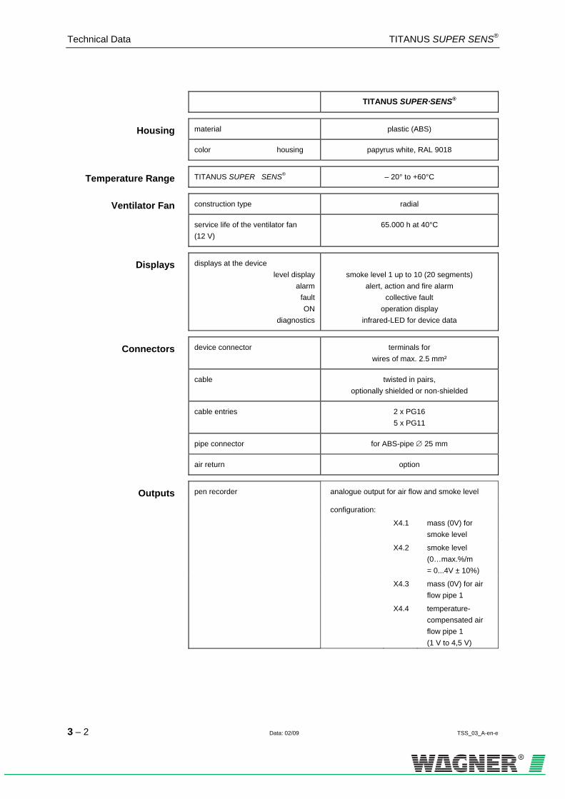
TITANUS SUPER·SENS®
Housing material plastic (ABS)
color housing papyrus white, RAL 9018
Temperature Range TITANUS SUPER · SENS® – 20° to +60°C
Ventilator Fan construction type radial
service life of the ventilator fan (12 V)
65.000 h at 40°C
Displays displays at the device level display
alarmfaultON
diagnostics
smoke level 1 up to 10 (20 segments)
alert, action and fire alarm collective fault
operation display infrared-LED for device data
Connectors device connector terminals for wires of max. 2.5 mm²
cable twisted in pairs, optionally shielded or non-shielded
cable entries 2 x PG16 5 x PG11
pipe connector for ABS-pipe ∅ 25 mm
air return option
Outputs pen recorder analogue output for air flow and smoke level
configuration:
X4.1 mass (0V) for smoke level
X4.2 smoke level (0…max.%/m = 0...4V ± 10%)
X4.3 mass (0V) for air flow pipe 1
X4.4 temperature- compensated air flow pipe 1 (1 V to 4,5 V)

TITANUS SUPER·SENS® Technical Data
TSS_03_A-en-e Data: 02/09 3 – 3
TITANUS SUPER·SENS®
Display Sensitivity Level
Sensitivity
I
0.02% light obscuration/m
II
0.01% light obscuration /m
III
0.005% light obscuration /m
IV
0.0025% light obscuration /m
3.2 Accessories – TITANUS®
Remote displays for TITANUS SUPER·SENS®
Remote Displays voltage 15 to 30 V DC
current consumption (at 24 V) quiescentmaximum
10 mA 65 mA
electrical connection lengths1 remote display
2 remote displays
total length max. 1000 m total length max. 500 m
protection class IP 45
Displays displays at the device level display
alarmfaultON
diagnostics
smoke level 1 to 10
action, alert and fire alarm collective fault
operation display infrared-LED for device data
Connectors terminal block terminals for wires of max. 2.5 mm²
cable entry 2 x PG9

Technical Data TITANUS SUPER·SENS®
3 – 4 Data: 02/09 TSS_03_A-en-e
3.3 Pipe system TITANUS®
Pipe system for TITANUS SUPER·SENS®
Pipe system max. pipe lengthmax. number of air sampling points
200 m 24
max. length of air sampling hoseper ceiling lead through
1 m
temperature rangePVC-pipeABS-pipe
0°C. ..+60°C
-40°C…+80°C
max. monitoring area 2880 m2

TITANUS SUPER·SENS® Pipe Design
TSS_04_A-en-e Data: 02/09 4 – 1
4 Design
4.1 General
The following describes the project planning of the air sampling smoke detection system to EN 54-20. The basic conditions are described in Chapter 4.1. The project planning is to be conducted in accordance with Chapter 4.2. The limiting project planning instructions in accordance with Chapter 4.3 apply to special applications in addition to Chapter 4.2 These should be taken into consideration at the beginning of project planning for special projects. Project planning options according to EN 54-20: There are various technical solutions to be selected from, depending on the project planning criteria. The chapters for the solutions are listed in the following tables.
Project planning crite-rion
Technical solution Basic Prin-ciples
Limitations
General area monitoring Standard project planning Chapter 4.2 ---
Recognition of a failure at an individual aperture
Project planning for individual aperture monitoring
Chapter 4.2 Chapter 4.3.1
Device protection/cabinet monitoring
Simplified pipe project planning Chapter 4.2 Chapter 4.3.2
Long intake lines Project planning with long intake lines Chapter 4.2 Chapter 4.3.3
Ventilation conduits Project planning for forced air flow Chapter 4.2 Chapter 4.3.4

Pipe Design TITANUS SUPER·SENS®
4 – 2 Data: 02/09 TSS_04_A-en-e
4.1.1 Regulations
The current respective national regulations in each particular country must also be complied with and project planning must be adjusted to such regulations. EN 54-20 The air sampling smoke detection systems shall be planned in accor-dance with the project planning guidelines described in Chapter 4.2.1 in order to be compliant with EN 54-20.
The following guidelines must also be complied with for systems in ac-cordance with the requirements of VdS Schadenverhütung: • "Guideline for automatic fire alarm systems, planning and installa-
tion", VdS Schadenverhütung GmbH, Cologne, Germany (VdS 2095) • "Local application protection for electric and electronic equipment -
rules for planning and installation" guideline, VdS Schadenverhütung GmbH, Cologne, Germany (VdS 2304)
• The technical bulletin “Project Planning for air sampling fire alarms” VdS Schadenverhütung GmbH, Cologne, Germany (VdS 3435)
The following national regulations must also be complied with in Ger-many, for instance: • DIN VDE 0833 part 1 and 2 "Alarm systems for fire, intrusion und
hold-up" • Additional regulations for installing fire alarm systems which are laid
down by fire authorities and building supervisory boards or building regulation authorities and are only valid locally.

TITANUS SUPER·SENS® Pipe Design
TSS_04_A-en-e Data: 02/09 4 – 3
4.1.2 Pipe system
When planning the pipe system, it must be ensured that reliable fire de-tection is guaranteed for any fire present in an installation or in a moni-tored area. Fig. 4.1 depicts an example of a U-pipe system with symmet-rical or asymmetrical design and the diameters of the aspiration aper-tures calculated according to Chapter 4.6.2 “Standard planning.” The number of the intake apertures and the pipe system design depends on the size, ventilation and shape of the monitored area. The aspiration apertures should be planned like point-type detectors. The pipe system is to be fitted in accordance with the project planning guidelines in this sec-tion while taking the following points into consideration:
Symmetrical design The pipe system should preferably have a symmetrical design, i.e.: • equal number of aspiration apertures per pipeline branch • equal lengths of pipeline (must not exceed ± 20 % deviation) • equal distance between neighbouring aspiration apertures on the
smoke aspiration pipe (must not exceed ± 20 % deviation)
Asymmetrical design The following specifications apply in the event that pipe system must be laid out asymmetrically due to structural conditions (see also Fig. 4.1): • The number of aspiration apertures as well as the length of the
shortest and longest pipeline branch in the pipe system must not ex-ceed a quantity or length ratio of 1:2.
• The distances between adjacent aspiration apertures in the sampling pipe must be identical (should not exceed deviation of ±20%).
• The diameters of the aspiration apertures are determined for each pipeline branch individually and depend on the number of aspiration apertures on the pipeline branch in question. The commensurate aperture diameters can be found in the tables in Chap. 4.2.4.
TITANUS
TITANUS4,2 5,6 6,8
®
®
3,8 4,03,8 4,0 4,44,2
3,8 4,03,8 4,0 4,44,2
3,8 4,03,8 4,0 4,44,2
symmetrical pipe system
asymmetrical pipe system
Fig. 4.1: Example of a symmetrical and an asymmetrical U-pipe system

Pipe Design TITANUS SUPER·SENS®
4 – 4 Data: 02/09 TSS_04_A-en-e
Longer pipe intake lines Pipes with a diameter of 32mm or 40mm may be used for long pipe in-
take lines in accordance with the chapter "Special project planning". This reduces the air resistance of the pipe intake line or makes it possible to achieve a greater equilibrium for sampling via outgoing transmission lines.
Branch length In order to ensure a short transport time for the smoke fumes in the sam-pling pipe and thus enable rapid detection, it is better to plan several shorter than a few long ones (preferably a U- or double U-pipe system ).
Pipe designs 4 types of pipe designs can be selected, depending on the cabinet ge-
ometry (see Figure 4.2).
I- pipe An air sampling smoke detection pipe system without branches.
U- pipe An air sampling smoke detection pipe system which branches into 2 air sampling branches after the connection to the TITANUS®.
M-pipe An air sampling smoke detection pipe system which branches into 3 air sampling branches after the connection to the TITANUS®.
Double U-pipe An air sampling smoke detection pipe system which branches into 4 air sampling branches after the connection to the TITANUS®.

TITANUS SUPER·SENS® Pipe Design
TSS_04_A-en-e Data: 02/09 4 – 5
TITANUS
TITANUS
TITANUS
U-pipe system
Double-U-pipe system
I-pipe system
®
®
®
TITANUS ®
M-pipe system
Fig. 4.2: Pipe designs
Direction change Angles and bends in the pipe system increase flow resistance. For that
reason, it is necessary to limit the number of them to the amount re-quired. It is preferable to use bends, since angles have a higher flow resistance. Angles should therefore only be used where they are necessary due to structural constraints.
Corresponds to a straight pipe length of
Angle 1.5 m
Bend 0.3 m
If the pipe system includes angles or bends, the maximum overall length of the pipe system will be reduced. Bends are to be preferred over angles. An excessive number of changes in direction can change the detection time.
INSTRUCTION

Pipe Design TITANUS SUPER·SENS®
4 – 6 Data: 02/09 TSS_04_A-en-e
Special cases If the pipe system does not match the project planning guidelines de-scribed here due to structural constraints, WAGNER should make the in-dividual calculations for such a case.
Checking Check detection reliability with activation tests in cases where use of the system is critical. Also check whether an air flow rate is present at indi-vidual aspiration apertures. In order to increase the transport speed in critical areas the ventilator voltage can be set from 12 V to 15 V. Make sure that the current intake increases.
TIP

TITANUS SUPER·SENS® Pipe Design
TSS_04_A-en-e Data: 02/09 4 – 7
4.1.3 Air flow monitoring
EN 54-20 requires the recognition of a 20 percent change in the air flow volume by the detector module’s air flow sensor system. In order to ac-complish this, the air flow sensor system’s triggering threshold must be set to level III. But level I and II may also be set as an alternative. It is recommended to conduct an air pressure-dependent air flow compensa-tion for both of these settings. Any threshold desired may be set with systems which do not require EN 54-20 conformity. Project planning for the air flow monitoring system in sampling pipes is carried out while taking into consideration the respective national regula-tions for each country.
Graduation of the Air Sampling Points For a symmetric detection it is necessary that all air sampling points have
nearly the same air throughput. For this reason with large distances be-tween the air sampling points (> 2 m) the air sampling point diameters have to become larger towards the end of the pipe. The required diame-ters are given in the tables of the chapter 4.2.4.
Adjusting the air flow sensitivity The air flow sensor sensitivity must be adjusted to the application in
question. Breakage and stoppages must be detected reliability with low susceptibility to malfunction. The triggering threshold and the air flow sensor sensitivity can be ad-justed in 4 levels.
Level I II III IV
In conformity with EN 54-20
Triggering threshold Small Medium Large Very large
Sensitivity Very high High Medium Low
It is recommended to always select the greatest possible level which is permissible according to national standards.
TIP
Pipe Design TITANUS SUPER·SENS®
4 – 8 Data: 02/09 TSS_04_A-en-e
Level I limitations The air flow monitoring may only be set to level I if:
Project planning according to “Individual aperture monitoring” has been carried out (see Chap. 4.3.1 “Pipe project planning individual aperture monitoring”),
the air flow sensor has been compensated depending on the air pres-sure (see Chap. 7.1.2 “Air pressure dependent air flow compensation") and
No large air flow fluctuations occur.
Air pressure differences The same air pressure must be present throughout the sampling pipe.
If the air sampling smoke detection system and pipe system are in ar-eas with different air pressure, the air sampled by the TITANUS®
should be re-circulated in the pipe system pressure area (see Chapter 2.3.5 “Air recirculation”).
INSTRUCTION

TITANUS SUPER·SENS® Pipe Design
TSS_04_A-en-e Data: 02/09 4 – 9
4.1.4 Sensitivity
According to EN 54-20, the sensitivity of a air sampling smoke detection system can be divided into particular fire sensitivity classes. These sensi-tivity classes describe particular example applications in which the sys-tems can be used. Permissible system project planning can be deter-mined for each classification according to Chapter 4.2. Air sampling smoke detection systems with a higher sensitivity class ac-cording to EN 54-20 also meet the requirements of the lower classes.
Class Description Example application
A Air sampling smoke de-
tector with very high sensitivity
Very early detection: Highly diluted smoke in air
conditioned IT areas
B
Air sampling smoke de-
tector with increased sensitivity
Early detection: Diluted smoke in conventional
cooled IT areas.
C Air sampling smoke de-
tector with standard sensitivity
Standard detection: Fire detection with the benefits of air sampling smoke detection systems
The fire sensitivity classes A, B and C can be achieved with each de-tector module available, depending on the number of aspiration aper-tures.
The table shows the selectable sensitivity levels of the TITANUS ®:
Activation sensitivity (smoke level 10, fire alarm)
Level I 0.2% light obscuration/m
Level II 0.1% light obscuration/m (Standard)
Level III 0.05% light obscuration/m
Level IV 0.025% light obscuration/m
Project planning for the monitored surface is always carried out accord-ing to national specifications for point-shaped smoke detectors.
INSTRUCTION

Pipe Design TITANUS SUPER·SENS®
4 – 10 Data: 02/09 TSS_04_A-en-e
4.1.5 Project planning limits
The following limit values must be complied with at all times with the TITANUS® per pipe system connected:
The minimum pipe length between 2 aspiration apertures is 4 m.
The maximum pipe length between 2 aspiration apertures is 12 m.
The maximum overall pipe length is 200 m.
The maximum monitoring area per sampling aperture corresponds to the monitoring area of point-shaped detectors in accordance with the applicable project planning guideline.
A maximum of 24 aspiration apertures are possible per detector module.
The maximum overall monitoring area, the maximum overall pipe length and the maximum number of aspiration apertures are independent of the project planning selected, as are the restrictions from national regula-tions.

TITANUS SUPER·SENS® Pipe Design
TSS_04_A-en-e Data: 02/09 4 – 11
4.2 Project planning
4.2.1 Project planning guidelines
In order to conduct project planning in accordance with the EN 54-20 standard, it is necessary to be familiar with particular factors. These are the requirements for the system’s sensitivity, the number of aspiration apertures and the accessories necessary for the corresponding applica-tion. The pipe system design in conformity with the standard can be de-termined based on these factors using the following chapter and with the help of the project planning tables in the appendix.
4.2.1.1 Determining the necessary accessories
Since the accessory components, such as filters, have a certain influence on the dimension of the pipe planning, the suitable accessories must be selected for the corresponding application ahead of time. Retrofitting, with a fine filter, for instance, is generally only possible if a more sensitive detector module is being used or a particular reserve has been planned in advance. Components which have not been approved by WAGNER are used, CE conformity on the basis of EN 54-20 will not be possible.
The following accessory components should be taken into consideration in the process:
Air filter
Steam trap
Detector box
OXY·SENS® air sampling detector
The SD-1 noise suppressor may be used in any case with no project planning restrictions.
INSTRUCTION

Pipe Design TITANUS SUPER·SENS®
4 – 12 Data: 02/09 TSS_04_A-en-e
4.2.2 Pipe accessories
Air filters Type Application Examples
LF-AD Coarse filter for separating particles > approx. 15 µm
Dust, insects, fibres, hair, cinders, pollen
LF-AD-1 Filter for separating particles > approx. 10 µm
As above. Additionally: Colour pigments and fine dust
LF-AD-2 Fine filter for separating parti-cles > approx. 5 µm
As above. Additionally: Fine dust in low concen-trations
SF-400 Fine filter for separating parti-cles > approx. 1 µm
As above. Additionally: Fine dust in high concen-trations
SF-650 Fine filter for separating parti-cles > approx. 1 µm
As above, but with in-creased filter lifetime
Steam trap
Type Application
KA-DN-25 Condensation separator for applications with condensation mois-ture in the pipe
Sound suppressor
Type Application
SD-1 Sound suppressor for areas sensitive to noise
TITANUS SUPER·SENS® Pipe Design
TSS_04_A-en-e Data: 02/09 4 – 13
4.2.3 Sensitivity and pipeline project planning
4.2.3.1 Pipeline project planning with pipe accessories
The following project planning tables for pipeline project planning can be found in the appendix for each previously selected pipe accessory.
Project planning without filter
Project planning with LF-AD air filter
Project planning with LF-AD-1 air filter
Project planning with LF-AD-2 air filter
Project planning with SF-400 / SF-650 air filter
An area can be monitored with more than detection points than re-quired by the national guideline in order to improve an air sampling smoke detection system’s detection quality. In such case, the number of normatively required sampling points is to be used in calculating the required sensitivity of an air sampling smoke detection system.
INSTRUCTION

Pipe Design TITANUS SUPER·SENS®
4 – 14 Data: 02/09 TSS_04_A-en-e
Procedure In the following example, a project plan is supposed to fulfil class B re-quirements without air filters, with 8 apertures and with the additional use of a condensation separator. The red arrows show the possible project plans with varying pipe shapes and fan voltages.
Selection
Selection of the corresponding project planning table based on the air filter to be used (see Chap. 4.2.2 )
Result 1.
The project planning table has been determined
Selection
Selection of the number of aspiration apertures in the project planning table
Result 2.
The achievable sensitivity class for the selected number of apertures has been determined
Selection
Determinations on the sensitivity necessary to achieve the sensitivity class
Result 3.
Determination of the detector module and sensitivity setting
Selection Selection of other pipe components ( e.g. steam trap and detonation protection see Chap. 4.2.2 described components) Result
4.
The project planning table has been determined
Selection
Pipe length selection
Result 5.
Determination of the pipe shape and necessary fan voltage.

TITANUS SUPER·SENS® Pipe Design
TSS_04_A-en-e Data: 02/09 4 – 15
Pipe Design TITANUS SUPER·SENS®
4 – 16 Data: 02/09 TSS_04_A-en-e
Results: The following modules may optionally be used with the corresponding settings for class B or A:
setting the sensitivity on 0,025 % LT/m
setting the sensitivity on 0,05 % LT/m
setting the sensitivity on 0,1 % LT/m
setting the sensitivity on 0,2 % LT/m
Possible system parameters:
U- pipe system
- 12 V fan voltage, max. 90 m overall pipe length
- 15 V fan voltage, max. 130 m overall pipe length
M- pipe system,
- 12 V fan voltage, max. 120 m overall pipe length
- 15 V fan voltage, max. 170 m overall pipe length
Double U- pipe system,
- 12 V fan voltage, max. 140 m overall pipe length
- 15 V fan voltage, max. 200 m overall pipe length
TITANUS SUPER·SENS® Pipe Design
TSS_04_A-en-e Data: 02/09 4 – 17
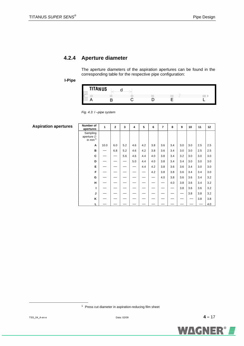
4.2.4 Aperture diameter
The aperture diameters of the aspiration apertures can be found in the corresponding table for the respective pipe configuration:
I-Pipe
A B C D E L
TITANUS d
Fig. 4.3: I –pipe system
Aspiration apertures Number of
apertures 1 2 3 4 5 6 7 8 9 10 11 12
Sampling aperture ∅
in mm0F
1)
A 10.0 6.0 5.2 4.6 4.2 3.8 3.6 3.4 3.0 3.0 2.5 2.5 B — 6.8 5.2 4.6 4.2 3.8 3.6 3.4 3.0 3.0 2.5 2.5 C — — 5.6 4.6 4.4 4.0 3.8 3.4 3.2 3.0 3.0 3.0 D — — — 5.0 4.4 4.0 3.8 3.4 3.4 3.0 3.0 3.0 E — — — — 4.4 4.2 3.8 3.6 3.6 3.4 3.0 3.0 F — — — — — 4.2 3.8 3.8 3.6 3.4 3.4 3.0 G — — — — — — 4.0 3.8 3.6 3.6 3.4 3.2 H — — — — — — — 4.0 3.8 3.6 3.4 3.2 I — — — — — — — — 3.8 3.6 3.6 3.2 J — — — — — — — — — 3.8 3.8 3.2 K — — — — — — — — — — 3.8 3.8 L — — — — — — — — — — — 4.0
1 Press cut diameter in aspiration-reducing film sheet

Pipe Design TITANUS SUPER·SENS®
4 – 18 Data: 02/09 TSS_04_A-en-e
U-Pipe
A B C D E J
TITANUS ®
Fig. 4.4: U –pipe system
Aspiration apertures Number of aper-tures
2 4 6 8 10 12 14 16 18 20
Sampling aperture ∅ in mm 1F
2)
A 7.0 6.8 4.2 4.6 4.2 3.8 3.4 3.2 3.0 2.5 B — 7.0 5.6 4.6 4.4 3.8 3.4 3.2 3.0 2.5 C — — 6.8 5.2 4.4 4.0 3.6 3.2 3.0 3.0 D — — — 5.2 4.4 4.0 3.8 3.4 3.2 3.0 E — — — — 4.6 4.2 3.8 3.6 3.2 3.0 F — — — — — 4.4 4.0 3.6 3.2 3.0 G — — — — — — 4.2 3.8 3.4 3.2 H — — — — — — — 4.0 3.8 3.2 I — — — — — — — — 4.0 3.8 J — — — — — — — — — 4,0
M-Pipe
TITANUS
A B C D E H
®
Fig. 4.5: M –pipe system
Aspiration apertures Number of aper-tures
3 6 9 12 15 18 21 24
Sampling aperture ∅ in mm2)
A 7.0 5.0 3.8 3.4 3.0 2.5 2.5 2.0 B — 5.6 4.2 3.6 3.2 2.5 2.5 2.0 C — — 5.0 4.0 3.2 3.0 2.5 2.5 D — — — 4.2 3.6 3.4 3.0 2.5 E — — — — 4.0 3.4 3.0 2.5 F — — — — — 3.8 3.2 3.0 G — — — — — — 3.6 3.4 H 3.6
2 Press cut diameter in aspiration-reducing film sheet
TITANUS SUPER·SENS® Pipe Design
TSS_04_A-en-e Data: 02/09 4 – 19
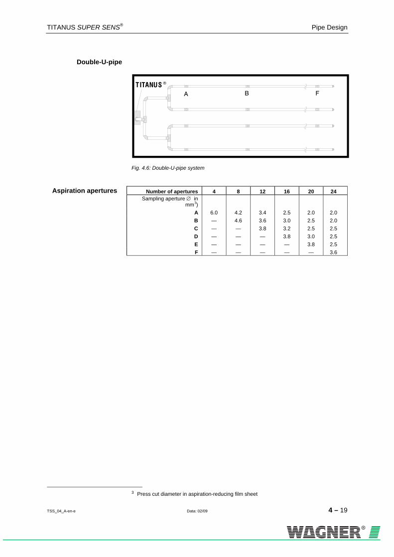
Double-U-pipe
TITANUS ®
A B F
Fig. 4.6: Double-U-pipe system
Aspiration apertures Number of apertures 4 8 12 16 20 24
Sampling aperture ∅ in mm 2F
3)
A 6.0 4.2 3.4 2.5 2.0 2.0 B — 4.6 3.6 3.0 2.5 2.0 C — — 3.8 3.2 2.5 2.5 D — — — 3.8 3.0 2.5 E — — — — 3.8 2.5 F — — — — — 3.6
3 Press cut diameter in aspiration-reducing film sheet

Pipe Design TITANUS SUPER·SENS®
4 – 20 Data: 02/09 TSS_04_A-en-e
4.3 Special project planning
4.3.1 Project planning for individual aperture monitoring
The following system parameters apply to the detection of an individual or a particular number of blocked aspiration apertures, depending on pipe configuration. The specifications according to Chapter 4.2 apply to project planning. The following limit values and aperture diameters should also be taken into account. Additional accessories (air filters, condensation separators, etc.) can influence the maximum pipe length.
4.3.1.1 I-Pipe system
TITANUS ®
A B C D E I JF
TITANUS d®
Fig. 4.7: I-Pipe system for area protection
Limit values Min. distance from TITANUS® to 1st sampling aperture 4 m
Max. distance from TITANUS® to 1st sampling aperture 20 m
Max. Distance from 1st sampling aperture to last 50 m
Max. Overall pipe length per pipe system 70 m
Min. distance between 2 aspiration apertures (d) 4 m
Max. distance between 2 aspiration apertures (d) 12 m
Max. number of aspiration apertures (n) per pipe system 10 pcs.
TITANUS SUPER·SENS® Pipe Design
TSS_04_A-en-e Data: 02/09 4 – 21
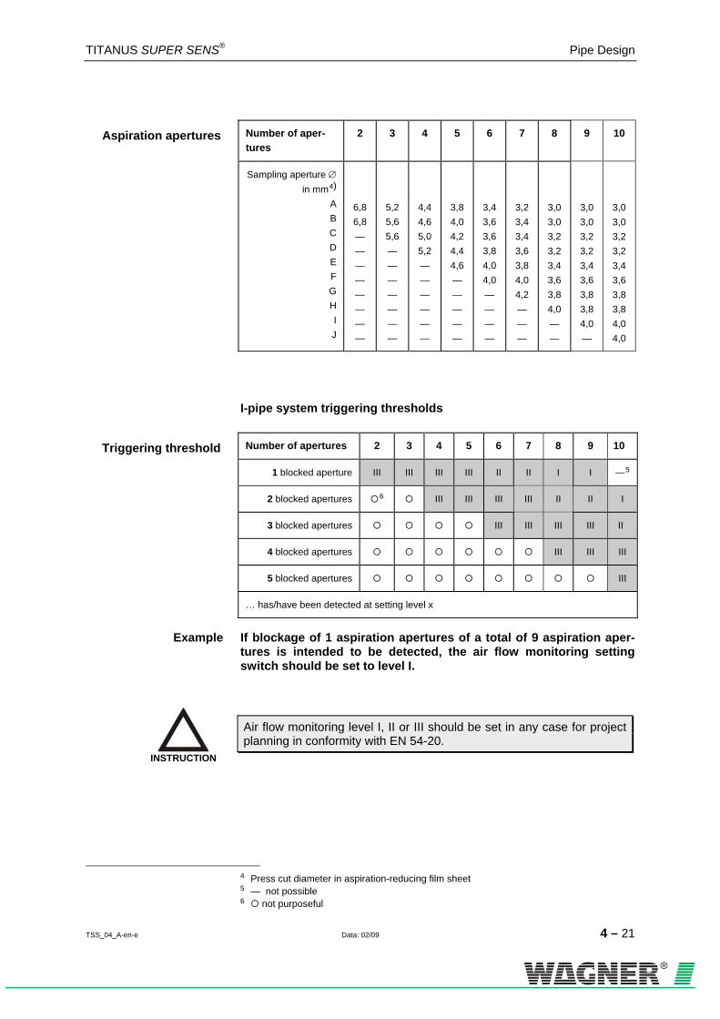
Aspiration apertures Number of aper-tures
2 3 4 5 6 7 8 9 10
Sampling aperture ∅ in mm 3F
4)
A B C D E F G H
IJ
6,86,8— — — — — — — —
5,25,65,6— — — — — — —
4,44,65,05,2— — — — — —
3,84,04,24,44,6— — — — —
3,43,63,63,84,04,0— — — —
3,2 3,4 3,4 3,6 3,8 4,0 4,2 — — —
3,0 3,0 3,2 3,2 3,4 3,6 3,8 4,0 — —
3,0 3,0 3,2 3,2 3,4 3,6 3,8 3,8 4,0 —
3,03,03,23,23,43,63,83,84,04,0
I-pipe system triggering thresholds
Triggering threshold Number of apertures 2 3 4 5 6 7 8 9 10
1 blocked aperture III III III III II II I I —4F
5
2 blocked apertures 5F
6 III III III III II II I
3 blocked apertures III III III III II
4 blocked apertures III III III
5 blocked apertures III
… has/have been detected at setting level x
Example If blockage of 1 aspiration apertures of a total of 9 aspiration aper-tures is intended to be detected, the air flow monitoring setting switch should be set to level I.
Air flow monitoring level I, II or III should be set in any case for project planning in conformity with EN 54-20.
4 Press cut diameter in aspiration-reducing film sheet 5 — not possible 6 not purposeful
INSTRUCTION

Pipe Design TITANUS SUPER·SENS®
4 – 22 Data: 02/09 TSS_04_A-en-e
4.3.1.2 U-Pipe system
TITANUS®
A B C D E H
® dTITANUS®
Fig. 4.8: U-Pipe system for area protection
Limit values Min. distance from TITANUS® to T-piece 4 m
Max. distance from TITANUS® to T-piece 20 m
Max. Branch length 60 m
Max. Overall pipe length per pipe system 120 m
Min. Distance between 2 aspiration apertures (d) 4 m
Max. Distance between 2 aspiration apertures (d) 12 m
Max. number of aspiration apertures (n) per pipe system 16 pcs.
Aspiration apertures Number of aper-tures per pipe system
2 4 6 8 10 12 14 16
Sampling aperture ∅ in mm 6F
7) A B C D E F
GH
7,0— — — — — — —
5,05,2— — — — — —
4,04,24,4— — — — —
3,63,63,83,8— — — —
3,0 3,2 3,2 3,4 3,4 — — —
3,0 3,0 3,2 3,2 3,4 3,4 — —
3,0 3,0 3,0 3,2 3,2 3,4 3,4 —
2,5 2,5 2,5 3,0 3,0 3,0 3,2 3,2
7 Press cut diameter in aspiration-reducing film sheet

TITANUS SUPER·SENS® Pipe Design
TSS_04_A-en-e Data: 02/09 4 – 23
U-pipe system triggering thresholds
per pipe system Number of aper-tures
2 4 6 8 10 12 14 16
1 blocked aperture III II I I —7F
8 — — —
2 blocked apertures 8F
9 III II II I I — —
3 blocked apertures III II II II I —
4 blocked apertures III III II II I
5 blocked apertures III III III II
6 blocked apertures III III III
7 blocked apertures III III
8 blocked apertures III III
… has/have been detected at setting level x
Example If blockage of 2 aspiration apertures of a total of 8 aspiration aper-tures is intended to be detected, the air flow monitoring setting switch should be set to level II.
Air flow monitoring level I, II or III should be set in any case for project planning in conformity with EN 54-20.
8 — not possible 9 not purposeful
INSTRUCTION

Pipe Design TITANUS SUPER·SENS®
4 – 24 Data: 02/09 TSS_04_A-en-e
4.3.1.3 M-Pipe system
TITANUS®
dTITANUS®
A B C D
Fig. 4.9: M-Pipe system for area protection
Limit values Min. distance from TITANUS® to T-piece 4 m
Max. distance from TITANUS® to T-piece 20 m
Max. Branch length 50 m
Max. Overall pipe length per pipe system 150 m
Min. Distance between 2 aspiration apertures (d) 4 m
Max. Distance between 2 aspiration apertures (d) 12 m
Max. number of aspiration apertures (n) per pipe system 12 pcs.
Aspiration apertures Number of apertures per pipe system
3 6 9 12
Sampling aperture ∅ in mm 9F
10) A B C D
5,6 — — —
4,0 4,2 — —
3,4 3,6 3,8 —
3,0 3,0 3,2 3,4
10 Press cut diameter in aspiration-reducing film sheet

TITANUS SUPER·SENS® Pipe Design
TSS_04_A-en-e Data: 02/09 4 – 25
M-pipe system triggering thresholds
per pipe system Number of apertures 3 6 9 12
1 blocked aperture III II I —10F
11
2 blocked apertures 11F
12 III III I
3 blocked apertures III III III
4 blocked apertures III III
5 blocked apertures III
6 blocked apertures III
… has/have been detected at setting level x
Example If blockage of 3 aspiration apertures of a total of 9 aspiration aper-tures is intended to be detected, the air flow monitoring setting switch should be set to level III.
Air flow monitoring level I, II or III should be set in any case for project planning in conformity with EN 54-20.
11 — not possible 12 not purposeful
INSTRUCTION

Pipe Design TITANUS SUPER·SENS®
4 – 26 Data: 02/09 TSS_04_A-en-e
4.3.1.4 Double-U-Pipe system
TITANUS®
D B A
TITANUSd
C
®
Fig. 4.10: Double -U-Pipe system for area protection
Limit values Min. distance from TITANUS® to T-piece 4 m
Max. distance from TITANUS® to T-piece 20 m
Max. Branch length 30 m
Max. Overall pipe length per pipe system 120 m
Min. Distance between 2 aspiration apertures (d) 4 m
Max. Distance between 2 aspiration apertures (d) 12 m
Max. number of aspiration apertures (n) per pipe system 16 pcs.
Aspiration apertures Number of aspiration apertures per pipe system
4 8 12 16
Sampling aperture ∅ in mm 12F
13) A B C
D
5,0 — — —
3,6 3,6 — —
3,0 3,0 3,0 —
2,5 2,5 2,5 2,5
13 Press cut diameter in aspiration-reducing film sheet

TITANUS SUPER·SENS® Pipe Design
TSS_04_A-en-e Data: 02/09 4 – 27
Double U-pipe system triggering thresholds
per pipe system Number of apertures 4 8 12 16
1 blocked aperture II I — —13F
14
2 blocked apertures III I I —
4 blocked apertures 14F
15 III II I
6 blocked apertures III II
8 blocked apertures III III
… has/have been detected at setting level x
Example If blockage of 2 aspiration apertures of a total of 8 aspiration apertures is intended to be detected, the air flow monitoring setting switch should be set to level I.
Air flow monitoring level I, II or III should be set in any case for project planning in conformity with EN 54-20.
14 — not possible 15 not purposeful
INSTRUCTION

Pipe Design TITANUS SUPER·SENS®
4 – 28 Data: 02/09 TSS_04_A-en-e
4.3.2 Simplified pipe project planning
Simplified project planning is used for equipment protection and in rooms with small dimensions. The advantage in this project planning is the uni-form diameters of the aspiration apertures. The specifications according to Chapter 4.2 apply to project planning. The following limit values and aperture diameters should also be taken into account. Additional accessories (air filters, condensation separators, etc.) can influence the maximum pipe length.
4.3.2.1 I-pipe system
TITANUS®
TITANUS ®
d
Fig. 4.11: I-pipe system, such as for equipment protection
Limit values Min. distance from TITANUS® to 1st sampling aperture 2 m
Max. distance from TITANUS® to 1st sampling aperture 10 m
Max. distance from the 1st sampling aperture to the last sampling aperture
18 m
Max. overall pipe length Ø 25 mm 20 m
Max. number of aspiration apertures (n) per pipe system 10 pcs.
Minimum distance between aspiration apertures (d) 0,5 m
Maximum distance between aspiration apertures (d) 2 m
Aspiration apertures Number of aper-tures
2 3 4 5 6 7 8 9 10
∅ of all aspiration apertures in mm 15F
16)
6,0
5,0
4,4
4,0
3,6
3,6
3,6
3,4
3,4
16 Press cut diameter in aspiration-reducing film sheet

TITANUS SUPER·SENS® Pipe Design
TSS_04_A-en-e Data: 02/09 4 – 29
4.3.2.2 U-pipe system
TITANUS®
TITANUS ®
d
Fig. 4.12: U-pipe system, such as for equipment protection
Limit values Min. distance from TITANUS® to 1st sampling aperture 2 m
Max. distance from TITANUS® to 1st sampling aperture 10 m
Max. distance from the 1st sampling aperture to the last sampling aperture
9 m
Max. overall pipe length Ø 25 mm 20 m
Max. number of aspiration apertures (n) per pipe system 14 pcs.
Minimum distance between aspiration apertures (d) 0,5 m
Maximum distance between aspiration apertures (d) 2 m
Aspiration apertures Number of aper-tures
2 4 6 8 10 12 14
∅ of all aspiration apertures in mm 16F
17) 7,0 5,0 4,4 3,8 3,2 3,0 3,0
17 Press cut diameter in aspiration-reducing film sheet

Pipe Design TITANUS SUPER·SENS®
4 – 30 Data: 02/09 TSS_04_A-en-e
4.3.2.3 M-pipe system
TITANUS®
dTITANUS®
Fig. 4.13: M-pipe system, such as for equipment protection
Limit values Min. distance from TITANUS® to 1st sampling aperture 2 m
Max. distance from TITANUS® to 1st sampling aper-ture
10 m
Max. distance from the 1st sampling aperture to the last sampling aperture
6 m
Max. overall pipe length Ø 25 mm 20 m
Max. number of aspiration apertures (n) per pipe sys-tem
15 pcs.
Minimum distance between aspiration apertures (d) 0,5 m
Maximum distance between aspiration apertures (d) 4 m
Aspiration apertures Number of aper-tures
3 6 9 12 15
∅ of all aspiration apertures in mm 17F
18) 6,0 4,2 3,6 3,0 2,5
18 Press cut diameter in aspiration-reducing film sheet

TITANUS SUPER·SENS® Pipe Design
TSS_04_A-en-e Data: 02/09 4 – 31
4.3.2.4 Double U-pipe system
TITANUS®
d
TITANUS ®
Fig. 4.14: Double U-pipe system, such as for equipment protection
Limit values Min. distance from TITANUS® to 1st sampling aperture 2 m
Max. distance from TITANUS® to 1st sampling aperture 10 m
Max. distance from the 1st sampling aperture to the last sampling aperture
5 m
Max. overall pipe length Ø 25 mm 20 m
Max. number of aspiration apertures (n) per pipe system 12 pcs.
Minimum distance between aspiration apertures (d) 0,5 m
Maximum distance between aspiration apertures (d) 2 m
Aspiration apertures Number of apertures per pipe system
4 8 12
∅ of all aspiration apertures in mm18F
19) 5,0 3,8 3,0
19 Press cut diameter in aspiration-reducing film sheet

Pipe Design TITANUS SUPER·SENS®
4 – 32 Data: 02/09 TSS_04_A-en-e
4.3.3 Project planning with long intake lines
Project planning for long pipe intake lines may only be carried out under use of pipes with a diameter of 32 mm or 40 mm.
Observe national regulations during project planning!
The pipe intake line here refers to the pipe system between the air sam-pling smoke detection system and the last T-piece (U- and double U- pipe system) and/or the 1st sampling aperture (I-pipe system).
The general pipeline project planning is limited by the use of long pipe in-take lines as follows:
1 m pipe with ∅ 32 mm replaces 2 m pipe with ∅ 25 mm 1 m pipe with ∅ 40 mm replaces 3 m pipe with ∅ 25 mm
A B C D E F
TITANUS ®
Project planning pipeline branch Ø 25mm see Chapter 4.2.3
pipe
inta
ke li
ne
Fig. 4.15: Example of a pipe system for project planning with long pipe intake lines
INSTRUCTION

TITANUS SUPER·SENS® Pipe Design
TSS_04_A-en-e Data: 02/09 4 – 33
4.3.4 Project planning for forced air flow
In case of project planning with forced air flow, please select the highest alarm level according to the international specifications.
4.3.4.1 Detection of climatic cabinets with circulating air
Fig. 4.16: Air flow in climatic cabinets with circulating air (air circulator)
Due to the known flow conditions a simplified pipe installation is espe-cially suitable for rooms which are ventilated by means of climatic cabi-nets with circulating air.
The pipe system is to be installed outside of the pressure area as detection in this area is not reliable due to high pressure and flow conditions!
The warmed up air in the room (e.g. caused by EDP-units) is aspirated through openings in the ceiling void or directly through air inlets of a cli-matic cabinet with circulating air. The air in the device is pressed by filter elements, if necessary, cooled or warmed up and then blown into the floor void of the room at the bottom side of the climatic cabinet. This results in an „air circulator“ which circulates the whole air in the room.
INSTRUCTION
INSTRUCTION

Pipe Design TITANUS SUPER·SENS®
4 – 34 Data: 02/09 TSS_04_A-en-e
Fig. 4.17: Monitoring possibilities of a climatic cabinet with circulating air
A room as illustrated in Fig. 4.17 is monitored by mounting a pipe system at the air inlet of the climatic cabinet with circulating air (refer to type 1). It is possible to install the pipe system at the air outlet (in the floor void) if no smoke particles are filtered in the climatic cabinet (refer to type 2).
In case of a detection through a pipe system before the air inlet or after the air outlet of a climatic cabinet with circulating air it is important that the room is not monitored if the climatic cabinet(s) is (are) not in opera-tion.
ATTENTION
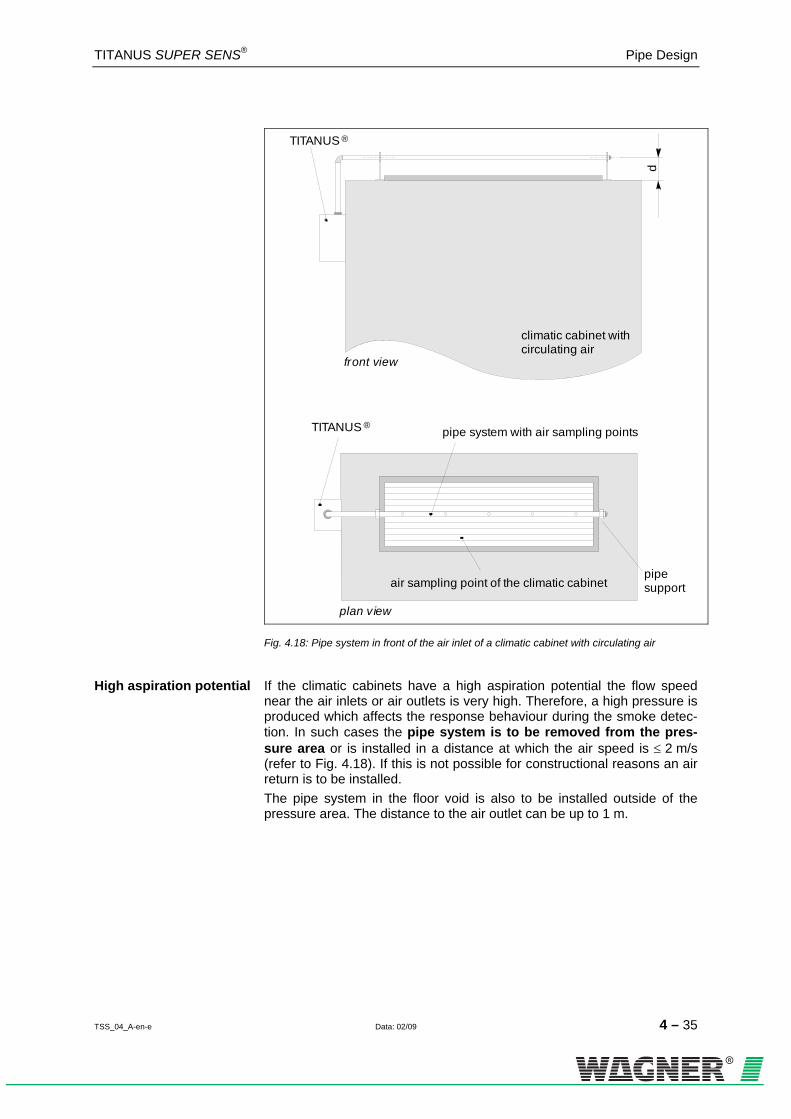
TITANUS SUPER·SENS® Pipe Design
TSS_04_A-en-e Data: 02/09 4 – 35
d
air sampling point of the climatic cabinet
TITANUS ®
TITANUS ®
climatic cabinet withcirculating air
pipe system with air sampling points
front view
plan view
pipe support
Fig. 4.18: Pipe system in front of the air inlet of a climatic cabinet with circulating air
High aspiration potential If the climatic cabinets have a high aspiration potential the flow speed near the air inlets or air outlets is very high. Therefore, a high pressure is produced which affects the response behaviour during the smoke detec-tion. In such cases the pipe system is to be removed from the pres-sure area or is installed in a distance at which the air speed is ≤ 2 m/s (refer to Fig. 4.18). If this is not possible for constructional reasons an air return is to be installed. The pipe system in the floor void is also to be installed outside of the pressure area. The distance to the air outlet can be up to 1 m.

Pipe Design TITANUS SUPER·SENS®
4 – 36 Data: 02/09 TSS_04_A-en-e
Fig. 4.19: Monitoring of climatic cabinets (scheme)
Air Sampling Points The air sampling points of the pipe system have to point towards the air flow (refer to Fig. 4.19). The optimum angle to the air flow direction is to be determined through a smoke test. The distance of the air sampling points depends on the design of the air inlet of the climatic cabinet. The air inlet of a climatic cabinet with circulat-ing air e.g. is often divided through lamellas or sound absorbers. The dis-tance between the air sampling points of the pipe system is to be chosen in such a way that the air sampling area is completely monitored. The size of the diameters is based on the number of air sampling points. For the exact values please refer to chapter 4.3.2 "Simplified Project Planning".)
Several climatic cabinets with 1 TITANUS® Several climatic cabinets can be monitored by means of one TITANUS® if
the following conditions are met: The climatic cabinets have to have the same design and have to be operated with the same voltage.
The climatic cabinets are always operated simultaneously (tandem operation).
In case of mutual operation the pipe system cannot be considered as symmetric anymore. TITANUS® is therefore in an unallowable operating state. Thus, only a limited smoke detection is possible. The customer is explicitly to be informed about this.
ATTENTION

TITANUS SUPER·SENS® Pipe Design
TSS_04_A-en-e Data: 02/09 4 – 37
Fig. 4.20: Monitoring of 2 climatic cabinets with two TITANUS®
Several climatic cabinets with several TITANUS® If the conditions (same design of the climatic cabinets, tandem operation
etc.) cannot be fulfilled a separate pipe system and one TITANUS® is to be installed at each climatic cabinet (refer to Fig. 4.20)

Pipe Design TITANUS SUPER·SENS®
4 – 38 Data: 02/09 TSS_04_A-en-e
4.3.4.2 Detection of air conditioning ducts
Air conditioning duct monitoring Air conditioners are distinguished between low-speed and high-speed
systems (see table below). The specifications provided in this chapter apply only to low-speed systems. There are not enough empirical val-ues available for high-speed systems. For that reason, smoke tests should be conducted with air conditioning ducts having flow rates higher than 10 m/s and the optimum response characteristics should be deter-mined.
Low-speed systems High-speed systems
Flow rate 10 m/s maximum > 10 m/s
Duct cross section Large Small
Pressure differential along the direction of
flow
Low High
The rate distribution in an air conditioning duct looks like this:
Fig. 4.21: Rate distribution in an air conditioning duct with v1 > v2 > v3 > v4
Sampling The pipe system should be arranged in area v1 to v3 in order to achieve optimum detection results.
Installation location of the pipe system The air exhaust duct should be chosen as the installation location of the
pipe system and should be as far away from sound suppressors, air baf-fles and bends as possible. The benchmark for the distance from such ‘obstacles’ is: At least 3x the smallest duct diameter.

TITANUS SUPER·SENS® Pipe Design
TSS_04_A-en-e Data: 02/09 4 – 39
If it is absolutely necessary to attach the pipe system directly behind baf-fles, sound suppressers or angles, the main flow speed areas will have to be monitored (see Fig. 4.22/23).
Fig. 4.22: Change in direction of a duct without baffles
sound absorption
main speed area
hole
air sampling pipe
air conditioning duct
Fig. 4.23: Sound suppressors in a duct
The following must be taken into consideration when installing a pipe sys-tem in air conditioning ducts: • Air recirculation (see following page) should be planned for, since
the TITANUS® and the pipe system are located in different pressure areas.
• The pipe inlets in the duct must be sealed so that they are air tight. • The part of the pipe system located outside of the duct must be
sealed so as to be air tight.

Pipe Design TITANUS SUPER·SENS®
4 – 40 Data: 02/09 TSS_04_A-en-e
Fig. 4.24: Air return
Air return The air return must take place at a distance of at least 2 m from the sam-pling. The open end of the air recirculation should be bevelled at a 45° angle (see Fig. 4.24).
10 9 8 7 6 5 4 3 2 1
TITA
NUS
SUP
ER ·S
ENS
®
Fig. 4.25: Offset air recirculation reengagement
If a distance of 2 m cannot be maintained, the pipes will have to be ar-ranged in an offset manner. This make makes it possible to achieve a drop of pressure between the intake air and exhaust air, since the pipes are located in different flow rate areas.

TITANUS SUPER·SENS® Pipe Design
TSS_04_A-en-e Data: 02/09 4 – 41
The distances of the aspiration apertures to each other and to the wall of the duct are represented in the following table.
Bore distance Duct cross section ≤ 0.5 m²
Duct cross section > 0.5 m²
Distance from aspiration apertures to wall
100 to 200 mm 200 to 300 mm
Distance of aspiration apertures to one an-
other
100 mm 150 mm
Sampling aperture diameter The diameter of the sampling aperture results from the number of aspira-
tion apertures. The precise value can be found in Chapter 4.3.2 "Simpli-fied pipeline project planning”. The pipe is concluded with an end cap without a bore.
Arrangement The aspiration apertures should be arranged against the air flow. During project planning, it is to be taken into account that the air condi-tioning ducts for mounting the pipe system are often only accessible from two sides.
Example The following illustration depicts two project planning examples of pipe systems in air conditioning ducts.
Fig. 4.26: Ducts with small and large duct cross-section

Pipe Design TITANUS SUPER·SENS®
4 – 42 Data: 02/09 TSS_04_A-en-e
4.4 Mains supply
The alarm-ready status in the fire protection system and the aperture of an alarm are taken into account when rating the external mains supply. In the system's alarm-ready status, the mains supply must supply standby current to the air sampling smoke detection systems and ensure that the emergency power batteries are charging in accordance with DIN VDE 0833 Part 1.19F
20 The following formulae apply in the event of an alarm:
Current calculation The current in the event of an alarm is calculated using the following for-mula:
Room Protection .max,supmaxmax., )( plypowerareaquiescentareaalarmroomtotal InnInII ≤−+⋅=
Equipment Protection powerquiescentalarmequipmenttotal InnInII .max)( ≤−+⋅=
The power for charging the batteries is calculated as follows:
Charging Current 248,0 minarg alnoingch
KI
⋅≈
max.y,powersupplchargingquiescentequipmenttotal IInII ≤+⋅=,
Itotal = total power supply of all connected air sampling systems in [A] Ipowersupply, max. = max. supply current of the power supply unit in [A] n = total number of all air sampling systems connected to a power supply unit
nmax area = total number of all air sampling systems in the area with the highest power consumption
Ialarm = alarm current of an air sampling system in [A] Iquiescent = quiescent current of an air sampling system in [A] Knominal = nominal capacity of the batteries in [Ah] Icharging = charging current of batteries (within 24h 80% of nominal capacity in [A]
The calculated total current (I ges) with the highest value is used for the configuration of the power supply units!
The power consumption of TITANUS® is listed in chapter 3, "Technical Data".
20 80% load in 24 hours
INSTRUCTION

TITANUS SUPER·SENS® Pipe Design
TSS_04_A-en-e Data: 02/09 4 – 43
Line calculation The maximum line length results from the permissible drop in voltage on the input line. The permissible drop in voltage is the difference of the final discharging voltage of the emergency power battery (21.5 V) and the low-ermost operating voltage limit of the air sampling smoke detection sys-tems.
2max
⋅⋅Δ⋅
=totalI
AUL γ
Lmax = maximum length of line in [m] A = cable cross sectiont in [mm²] Itotal = total current of air sampling systems in [A] γ = conductivity: Cu=57m/Ωmm² ΔU = max. voltage drop of the feeding line
A suitable cable feed through should be selected for the existing cable in order to ensue that the housing is tight.
M 25- cable feed through: ∅ 9 to 14 mm
M 20- cable feed through: ∅ 8 to 12 mm Emergency power calculation The nominal capacity is calculated using the following formula:
25.1)5.0(min ⋅⋅+⋅⋅= hItnIK totalquiescentalno
Knominal = nominal capacity of emergency power batteries [Ah] t = required bridging time in [h]
The factor 1.25 of the equation is only relevant in case of a bridging time of 24 hours or less.

Pipe Design TITANUS SUPER·SENS®
4 – 44 Data: 02/09 TSS_04_A-en-e

TITANUS SUPER·SENS® Installation
TSS_05_A-en-e Data: 02/09 5 – 1
5 Installation of TITANUS®
5.1 General
The regulations, guidelines and instructions given in chapter 4.1 are valid. When installing the TITANUS® air sampling system, the following must be taken into consideration: 1. there should be no changes made to the equipment. Where this is
unavoidable the operator, manufacturer and/or supplier must be in-formed (written approval)
2. any changes in the supply network (230 V/400 V supply) and exter-nal supply systems must be carried out by the system owner. This includes e.g.: • the primary connection of the supply units • any connections to external systems (e.g. central units) • planning of possible additional lightning protection and voltage
surge protection, which conform to standards

Installation TITANUS SUPER·SENS®
5 – 2 Data: 02/09 TSS_05_A-en-e
5.2 Opening the TITANUS® air sampling smoke detection system
Fig. 5.1: Opening the TITANUS® air sampling smoke detection system
The components on the base board are not allowed to be touched with-out an antistatic set (except for DIL-switches and buttons)!
Antistatic set ESD- protective mat set, e.g. type 8531
(art.-no. 85-20-4900)
In order to open TITANUS SUPER · SENS® follow the steps below (refer to 0HFig. 5.1).
Loosen the four screws on the housing lid and lift the lid carefully.
Pull the cable off the display board. Now remove the lid.
ATTENTION

TITANUS SUPER·SENS® Installation
TSS_05_A-en-e Data: 02/09 5 – 3
5.3 Settings
5.3.1 Base board
Fig. 5.2: Settings on the base board of TITANUS®
Contact I (9) of the switch S2 has no function.
5.3.1.1 Delay Period of the Air Flow Fault
Delay Period Set the delay period for the transmission of the fault signal via the switch S2 (A, B) on the base board (refer to 1HFig. 5.2) of TITANUS®.
Setting of the Delay Period Switch S2 Contact A (1)
Switch S2 Contact B (2)
0.5 minutes off on
2 minutes (standard) on off
15 minutes on on
60 minutes off off
As a standard a delay period of 2 minutes is set. In areas with faults lim-ited in time (e.g. air pressure variations) other delay periods – depending on the duration of the faults – should be set.
TIP

Installation TITANUS SUPER·SENS®
5 – 4 Data: 02/09 TSS_05_A-en-e
5.3.1.2 Activating Threshold of the Air Flow Monitoring
Set the activating threshold of the air flow fault via the switch S2 (C, D) on the base board (refer to 2HFig. 5.2) of TITANUS®.
Level Activating Thresholds Switch S2 Contact C (3)
Switch S2 Contact D (4)
I small on off
II medium off on
III large (standard) off off
IV very large on on
Choose the activating threshold acc. to chapter 4, "Project Planning".
5.3.1.3 Delay Period of the Alarm Activation
The delay period for the alarm thresholds can be set via the switch S2 (E, F). As a standard the delay period for alert, action and fire alarm is set to 10 s. If the smoke level increases during operation so that one of the alarm thresholds is reached the delay period starts. After the delay period has been expired the signal is transmitted if the alarm remains activated. Thus, a false alarm can be avoided in case of short interferences (dust).
Alarm Delay Period
Switch S2 Contact E (5)
Switch S2 Contact F (6)
0 seconds off off
10 seconds (standard) on off
30 seconds off on
60 seconds on on
For TITANUS® with a sensitivity level IV an alarm delay period of 30 s is recommended.
TIP

TITANUS SUPER·SENS® Installation
TSS_05_A-en-e Data: 02/09 5 – 5
5.3.1.4 Setting of the Response Sensitivity
The sensitivity of the detector head is usually set via the switch S2 (G, H) on the base board (refer to 3HFig. 5.2) of TITANUS®. The following table shows the response sensitivity (fire alarm) of TITANUS®.
Level TITANUS® Switch S2 Contact G (7)
Switch S2 Contact H (8)
I 0,2%/m on on
II 0,1%/m (Standard) off on
III 0,05%/m on off
IV 0,025 %/m off off
5.3.1.5 Fault and Alert Alarm Display
The display for collective faults (air flow and detector head fault) as well as the display and signal of the alert alarm can be set latched (standard) or non-latched. A homogenous setting can only be effected via switch S2, contact J (refer to 4HFig. 5.2) of TITANUS®.
Fault and Alert Alarm Signal Switch S2
Contact J (10)
latched (standard) on
non-latched off
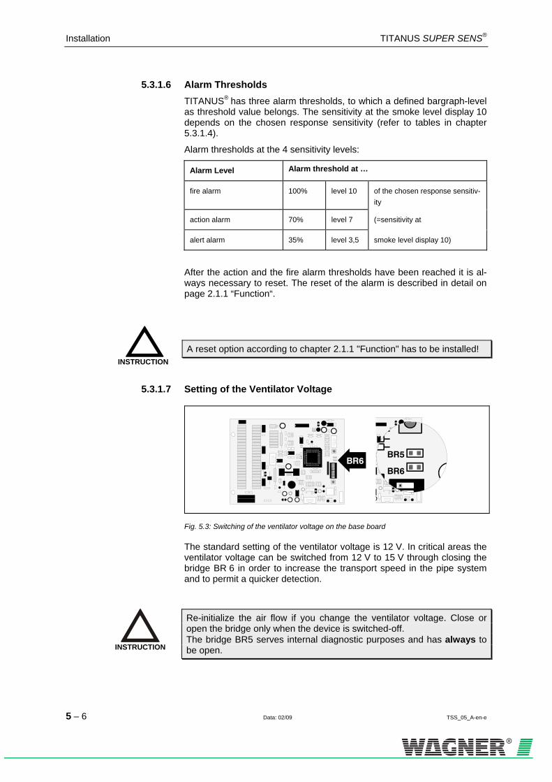
Installation TITANUS SUPER·SENS®
5 – 6 Data: 02/09 TSS_05_A-en-e
5.3.1.6 Alarm Thresholds TITANUS® has three alarm thresholds, to which a defined bargraph-level as threshold value belongs. The sensitivity at the smoke level display 10 depends on the chosen response sensitivity (refer to tables in chapter 5.3.1.4).
Alarm thresholds at the 4 sensitivity levels:
Alarm Level Alarm threshold at …
fire alarm 100% level 10 of the chosen response sensitiv-ity
action alarm 70% level 7 (=sensitivity at
alert alarm 35% level 3,5 smoke level display 10)
After the action and the fire alarm thresholds have been reached it is al-ways necessary to reset. The reset of the alarm is described in detail on page 2.1.1 “Function“.
A reset option according to chapter 2.1.1 "Function" has to be installed!
5.3.1.7 Setting of the Ventilator Voltage
Fig. 5.3: Switching of the ventilator voltage on the base board
The standard setting of the ventilator voltage is 12 V. In critical areas the ventilator voltage can be switched from 12 V to 15 V through closing the bridge BR 6 in order to increase the transport speed in the pipe system and to permit a quicker detection.
Re-initialize the air flow if you change the ventilator voltage. Close or open the bridge only when the device is switched-off. The bridge BR5 serves internal diagnostic purposes and has always to be open.
INSTRUCTION
INSTRUCTION
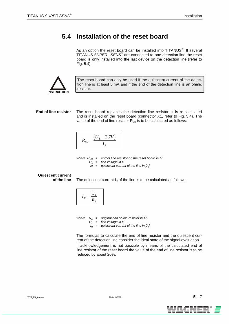
TITANUS SUPER·SENS® Installation
TSS_05_A-en-e Data: 02/09 5 – 7
5.4 Installation of the reset board
As an option the reset board can be installed into TITANUS®. If several TITANUS SUPER · SENS® are connected to one detection line the reset board is only installed into the last device on the detection line (refer to 5HFig. 5.4).
The reset board can only be used if the quiescent current of the detec-tion line is at least 5 mA and if the end of the detection line is an ohmic resistor.
End of line resistor The reset board replaces the detection line resistor. It is re-calculated and is installed on the reset board (connector X1, refer to 6HFig. 5.4). The value of the end of line resistor RER is to be calculated as follows:
( )RU V
IERL
R
=− 2 7,
where RER = end of line resistor on the reset board in Ω UL = line voltage in V IR = quiescent current of the line in [A]
Quiescent current of the line The quiescent current IR of the line is to be calculated as follows:
I URR
L
E
=
where RE = original end of line resistor in Ω UL = line voltage in V IR = quiescent current of the line in [A]
The formulas to calculate the end of line resistor and the quiescent cur-rent of the detection line consider the ideal state of the signal evaluation. If acknowledgement is not possible by means of the calculated end of line resistor of the reset board the value of the end of line resistor is to be reduced by about 20%.
INSTRUCTION
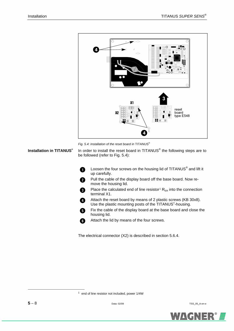
Installation TITANUS SUPER·SENS®
5 – 8 Data: 02/09 TSS_05_A-en-e
Fig. 5.4: Installation of the reset board in TITANUS®
Installation in TITANUS® In order to install the reset board in TITANUS® the following steps are to be followed (refer to 7HFig. 5.4):
Loosen the four screws on the housing lid of TITANUS® and lift it up carefully.
Pull the cable of the display board off the base board. Now re-move the housing lid.
Place the calculated end of line resistor 0F
1 RER into the connection terminal X1.
Attach the reset board by means of 2 plastic screws (KB 30x8). Use the plastic mounting posts of the TITANUS®-housing.
Fix the cable of the display board at the base board and close the housing lid.
Attach the lid by means of the four screws.
The electrical connector (X2) is described in section 5.6.4.
1 end of line resistor not included, power 1/4W

TITANUS SUPER·SENS® Installation
TSS_05_B-en-e Data: 02/09 5 – 9
5.5 Mounting Location
5.5.1 Fixing of the air sampling system TITANUS®
pipe adaptertype RA-AD2
arcs/elbows 90°
air sampling pipe
Fig. 5.5: Protection against impurities and dripping water during the installation of
TITANUS®
Mount the air sampling system so that the displays are clearly visible. If necessary install a remote display unit. The air sampling smoke detection system is either directly mounted on a wall with its bottom casing or by means of a special support (refer to chapter 2.2.5 "Device Supports"). The air outlet of the air sampling smoke detection system is not allowed to be blocked. The distance between the air outlet of TITANUS® and e.g. a wall is to be at least 10 cm. The air sampling system TITANUS® can be mounted with the air sam-pling pipe connectors pointing upwards or downwards. If necessary turn the lid by 180°.
Aspiration Downwards If TITANUS® is mounted with the air sampling pipe connectors pointing downwards it is to be guaranteed that no impurities or dripping water en-ter the air outlet which then points upwards. If necessary use the pipe adapter with a short pipe curving downwards (refer to 0HFig. 5.5).
Mounting Material TITANUS® cylinder or flat head screws
– diameter of thread: max. 6 mm – diameter of head: 10 up to 12 mm
Support (type H-AD2)
cylinder or flat head screws – diameter of thread: max. 4 mm – diameter of head: 5 up to 7 mm

Installation TITANUS SUPER·SENS®
5 – 10 Data: 02/09 TSS_05_B-en-e
Distances of the Holes The distances of the holes are given in the following figures (all dimensions in mm).
Fig. 5.6: Hole distances TITANUS® without support
Fig. 5.7: Hole distances of the support type H-AD2

TITANUS SUPER·SENS® Installation
TSS_05_B-en-e Data: 02/09 5 – 11
5.5.2 Connection of the air sampling pipe
Fig. 5.8: Connection of the air sampling pipe to the TITANUS®
Connection of air sampling pipe In order to connect the air sampling pipe to TITANUS®, attach the
pipe to the corresponding jack (refer to 1HFig. 5.8).
Do not use any adhesive to connect the air sampling pipe with the jack.
INSTRUCTION
Installation TITANUS SUPER·SENS®
5 – 12 Data: 02/09 TSS_05_B-en-e
5.6 Electrical Connection
In order to prepare the electrical connections follow the steps below: 1. Break through the cable entries e.g. by means of a screw driver. 2. Attach the plastic connection pieces PG16 or PG11. 3. Pass the cable through the corresponding PG-entries and a ferrite
ring each. 4. Pass the metallic grounding cable through the insulating hose.
Insulate the metallic grounding cable by the included hose so that a con-tact with the metallic detector head is avoided.
The electrical connection is effected via terminal block X1 and X2 on the base board of TITANUS®. Pay attention to the allowed cable cross sec-tions of the corresponding screw joint and the allowed wire cross sec-tions of the terminals (refer to chapter 3 "Technical Data").
The relay contacts on the base board can be used e.g. for the connection to a central fire panel or the triggering of signal devices, guiding systems etc. If the "alt Sense"-output has a permanent voltage of +24V the sensitivity is automatically switched to the next less sensitive level. If the voltage at the reset-input is permanently +24V all signals (action and fire alarm included) are automatically reset if the cause of the fault has been eliminated (action and fire alarm are non-latched).
Connection works are only allowed if the device is current less.
INSTRUCTION
TIP
ATTENTION

TITANUS SUPER·SENS® Installation
TSS_05_B-en-e Data: 02/09 5 – 13
5.6.1 Connection diagram
Fig. 5.9: Overview of terminals of TITANUS®

Installation TITANUS SUPER·SENS®
5 – 14 Data: 02/09 TSS_05_B-en-e
5.6.2 Connection without central fire panel
Fig. 5.10: Example of the connection of several TITANUS® without central fire panel, with
reset button and switch to change-over to 2nd sensitivity
Prefer shielded cables in order to increase the safety against faults.
INSTRUCTION

TITANUS SUPER·SENS® Installation
TSS_05_B-en-e Data: 02/09 5 – 15
5.6.3 Connection to central fire panel with reset button or relay contact
Fig. 5.11: Connection of several TITANUS® with central fire panel, reset button and switch
to change over to 2nd sensitivity
Prefer shielded cables in order to increase the safety against faults.
INSTRUCTION

Installation TITANUS SUPER·SENS®
5 – 16 Data: 02/09 TSS_05_B-en-e
5.6.4 Connection to central fire panel with reset board
Fig. 5.12: Connection of several TITANUS® with central fire panel, reset board and switch
to change over to 2nd sensitivity
Prefer shielded cables in order to increase the safety against faults.
INSTRUCTION

TITANUS SUPER·SENS® Installation
TSS_05_B-en-e Data: 02/09 5 – 17
5.7 Application of TITANUS® and fire detc-tion system AlgoRex®
In general, there are different possibilities to connect the potential-free alarm and fault contacts of the air sampling smoke detection system TITANUS® to the smoke detection system AlgoRex®. • the collective connection • the use of line modules of the AnalogPLUS®-technology • the connection by means of interactive line modules
5.7.1 Collective connection
TITANUS® can be connected to a collective line board (belongs to the central unit) of the smoke detection system AlgoRex®. For each used alarm contact a collective detection line is required. It is possible to con-nect the fault contact either separately to the collective line board or to in-tegrate it into the alert alarm-detection line. 2HFig. 5.13 illustrates the cor-rect connection at TITANUS®.
Pay attention to the correct polarity when using the 5.6V-Z-diodes.
INSTRUCTION

Installation TITANUS SUPER·SENS®
5 – 18 Data: 02/09 TSS_05_B-en-e
5.7.1.1 Connection diagram collective
X1
R
R
R
L2-
L3-
L2-
Leitungswiderstand1)
2)
Leitungskapazität
RE (E3M080 Index < BDo. SW<V4.4x)RE (E3M080 Index > BDu. SW>V4.4x)
Alarmkriterium (R )Siemens
Alarm
max. 250
max. 4 F
EOL22
Z-Diode 18V
Z-Diode 5,6Vund 47,5
Transzorb 20V
Transzorb 20V
max. 4 F
max. 150
L3-
L1-
L2+
L3+
0V
0V
0V
+24V
+24V
+24V
L1+
L2+
L3+
- Reset
- Data
0V
- LowSens.+LowSens.
+Reset
+Data
+24V
Rückstelltaster
Schalter 2.Sensibilität
("Ext. Disp.")
Anschluss: max 2,5mm 2
L1, L2, L3 : Meldelinienanschluss
L1+
L1-
47,5 5,6V
1
23
45678
9
Hauptalarm
Rückstellen("Reset")
2. Sensibilität("alt Sense")
101112
131415161718
1920
2122
1
23
45678
910 Voralarm
Störung 1
Infoalarm
11
12131415161718
1920
2122
X2
12345678910
11
12
13
14
15
16
17
18
19
20
21
22
12345678910
11
12
13
14
15
16
17
18
19
20
21
22
interne Beschaltung Grundplatine TITANUS®
RAlarm
RAlarm
2)
47,5 5,6V
2)
47,5 5,6V
R
47,5 5,6V
Fig. 5.13: Collective connection TITANUS ® with reset button and switch to change-over to
2nd sensitivity

TITANUS SUPER·SENS® Installation
TSS_05_B-en-e Data: 02/09 5 – 19
5.7.2 Application of TITANUS® with AlgoRex® line modules
TITANUS® can be connected to the AlgoRex®-smoke detection system through specific line modules (AnalogPLUS® or interactive). The installa-tion of max three line modules directly into the housing of TITANUS® is possible.
5.7.2.1 Installation of AlgoRex®-line modules in the TITANUS®- housing
TITANUS® is delivered without line modules and corresponding mounting kit type KIT_MSLB. The modules are to be mounted in order to complete the device. First of all open the device according to chapter 5.2.
Fig. 5.14: Mounting of the line modules into TITANUS®
In order to mount the line modules follow the steps below. A. Mounting of one module:
Fix the mounting sheet steel by means of the two included sheet metal screws at the bottom of the housing.
Place the module on the insert nuts of the mounting sheet steel and fix it by means of the two included M4x6-tallow-drop screws and the plain washers.

Installation TITANUS SUPER·SENS®
5 – 20 Data: 02/09 TSS_05_B-en-e
B. Mounting of up to three modules: Fix the mounting sheet steel by means of the two included sheet
metal screws at the bottom of the housing.
Place the module on the insert nuts of the mounting sheet steel and fix it by means of the two distance bolts and the plain wash-ers.
Place the second module exactly above the first module and at-tach it...
... by means of the two included M4x6-tallow-drop screws and the plain washers if you do not want to use a third module.
... by means of two distance bolts and the plain washers if you want to use a third module.
If required place the third module exactly above the second mod-ule and attach it by means of the two included M4x6-tallow-drop screws and the plain washers.

TITANUS SUPER·SENS® Installation
TSS_05_B-en-e Data: 02/09 5 – 21
5.7.2.2 TITANUS® and AnalogPLUS-Technology
Fig. 5.15: Connection with AnalogPlus-technology
Pay attention to the installation instructions delivered together with each line module.
INSTRUCTION

Installation TITANUS SUPER·SENS®
5 – 22 Data: 02/09 TSS_05_B-en-e
5.7.2.3 TITANUS® and interactive Technology
Fig. 5.16: Connection with interactive technology
Pay attention to the installation instructions delivered together with each line module.
INSTRUCTION
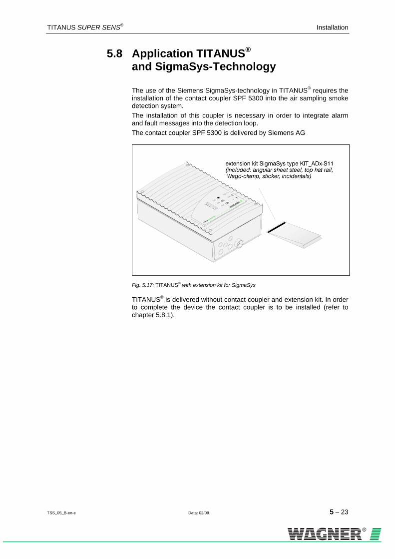
TITANUS SUPER·SENS® Installation
TSS_05_B-en-e Data: 02/09 5 – 23
5.8 Application TITANUS® and SigmaSys-Technology
The use of the Siemens SigmaSys-technology in TITANUS® requires the installation of the contact coupler SPF 5300 into the air sampling smoke detection system. The installation of this coupler is necessary in order to integrate alarm and fault messages into the detection loop. The contact coupler SPF 5300 is delivered by Siemens AG
Fig. 5.17: TITANUS® with extension kit for SigmaSys
TITANUS® is delivered without contact coupler and extension kit. In order to complete the device the contact coupler is to be installed (refer to chapter 5.8.1).

Installation TITANUS SUPER·SENS®
5 – 24 Data: 02/09 TSS_05_B-en-e
5.8.1 Mounting of the contact coupler SPF 5300 for the extension
Fig. 5.18: Mounting of the contact coupler SPF 5300
Mounting in TITANUS ® In order to install the contact coupler SPF 5300 into the air sampling
smoke detection system TITANUS® follow the steps below:
Open the device according to chapter 5.2.
Screw the top hat rail (A) onto the support angle (B). Use 2 flat head screws (C) M3x6, 2 tooth lock washers (D) and 2 hexagon nuts (E) M3.
Screw the support angle and the top hat rail (F) into the air sam-pling system. Use the 2 self-cutting screws (G).
Lock the SigmaSys-contact coupler SPF 5300 (H) edgewise on the top hat rail.
Connect the contact coupler (H) to TITANUS® according to the connection plan (refer to chapter 5.8.2).

TITANUS SUPER·SENS® Installation
TSS_05_B-en-e Data: 02/09 5 – 25
5.8.2 Electrical Connection The contact coupler is connected via the terminal blocks X1/ X2 on the connection board of TITANUS® and via the terminal block of the contact coupler SPF 5300. Pay attention to the permitted cable cross sections of the corresponding screw joint and the permitted wire cross sections of the terminals (refer to chapter 3 "Technical Data").
TITANUS® with Contact Coupler Connection of TITANUS® and contact coupler SPF 5300
Fig. 5.19: Connection with contact coupler SPF 5300 and TITANUS®

Installation TITANUS SUPER·SENS®
5 – 26 Data: 02/09 TSS_05_B-en-e
5.9 TITANUS® in the network system
As an option several TITANUS® can be connected to form a network. This network system permits the operator to monitor the states of all con-nected TITANUS®. The courses of the smoke level, the air flow values or the alarm and fault states e.g. are transmitted via the bus system. For the operation of TITANUS® in the network a special PC-software and a network board are necessary which are both not included.
5.9.1 Installation network board in TITANUS®
Fig. 5.20: Installation network board in TITANUS®
In order to install the network board open the air sampling smoke detec-tion system according to chapter 5.2. Then, follow the steps below:
Lock the three plastic distance pins in the prepared drill holes of the TITANUS® -base board.
Attach the 10-pole connection cable to plug X5 (SCI) of the TITANUS®-base board.
Lock the network board in the three plastic distance pins.
Attach the 10-pole connection cable with plug X2 of the network board.

TITANUS SUPER·SENS® Installation
TSS_05_B-en-e Data: 02/09 5 – 27
5.9.2 Connecting the network module
The network module connects the bus system with TITANUS®. Fig. 5.23 shows the electronic connections which must be carried out.
To operate TITANUS® within the network, further data about the bus sys-tem and PC software are required.
X1
X5
- U
b+
Ub
- U
b+
Ub
1 32 4 5 6 7 8
RJ45-Buchse
- TD
- RD
+ T
D
+ R
D
1 32 4
X4
X5 (SCI)
0V
+24V
connector: max 2,5mm 2
1
23
45678
9
fire alarm
reset("Reset")
2nd sensitivity ("alt Sense")
1011
12131415161718
1920
2122
alert alarm
X2
X11
2
3
123
123456789
10
11
12
13
14
15
16
17
18
19
20
21
22
20
21
22
19
20
21
22
- Ub
-
-
+
+
+ Ub
-
-
-
-
+
+
+
+
-+
0V+2
4V
base board TITANUS®
network module
Network cable KAT 5
RJ45-plug(Screened)
Fig. 5.21: Connecting the network board
INSTRUCTION

Installation TITANUS SUPER·SENS®
5 – 28 Data: 02/09 TSS_05_B-en-e
5.10 Remote display units
5.10.1 Connection of the remote display unit to TITANUS®
base board
TITANUS®
connector X2, External display
connector X2, 24V
Fig. 5.22: Connection remote display to TITANUS®
In order to install the remote display follow the steps below (refer to 3HFig. 5.22):
1. Loosen the four screws on the housing lid TITANUS® and lift it care-fully.
2. Pull the cable of the display board from the base board. Now remove the housing lid.
3. Break through the cable entries and attach the plastic connection pieces PG11.
4. Pass the fire detection cable through the PG11-connection piece of TITANUS® and a ferrite ring.
5. Connect the remote display to 24V and to the terminal X2. 6. Attach the cable of the display board at the base board and close the
housing lid. 7. Fix the housing lid by means of the four screws.

TITANUS SUPER·SENS® Installation
TSS_05_B-en-e Data: 02/09 5 – 29
5.10.2 Remote display housing design
Application of the front film sheet
Fig. 5.23: Application of the front film sheet to the remote display
The lid of the remote display can be turned by 180°. This allows the cable entries to be placed either on the top or on the bottom (refer to 4HFig. 5.23).
Wall Mounting The remote display in the housing is directly screwed to a wall with its bottom casing.
Mounting Material Remote Display Unit cylinder or flat-head screws – thread diameter: max. 4 mm – head diameter: 5 to 7 mm
Distances of the Holes The drill hole distances are illustrated in the following figure (all dimen-
sions mm).
Fig. 5.24: Drill hole distances in the housing

Installation TITANUS SUPER·SENS®
5 – 30 Data: 02/09 TSS_05_B-en-e
5.10.3 Remote display unit for 19" sub-rack
Fig. 5.25: Remote display and blind plate for 19"-subrack
To prepare the remote display and the blind plate for the installa-tion lock the included quick acting closures into the rectangular perforations of the front plate.
Place the quick acting closures into the sub-rack and fix them in the sub-rack by a quarter turn.
For the electrical connection refer to 5HFig. 5.26.
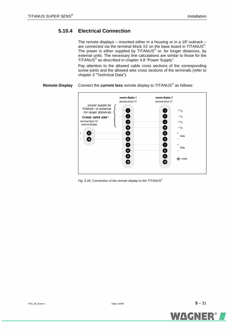
TITANUS SUPER·SENS® Installation
TSS_05_B-en-e Data: 02/09 5 – 31
5.10.4 Electrical Connection
The remote displays – mounted either in a housing or in a 19“-subrack – are connected via the terminal block X2 on the base board in TITANUS®. The power is either supplied by TITANUS® or, for longer distances, by external units. The necessary line calculations are similar to those for the TITANUS® as described in chapter 4.8 "Power Supply". Pay attention to the allowed cable cross sections of the corresponding screw joints and the allowed wire cross sections of the terminals (refer to chapter 3 "Technical Data").
Remote Display Connect the current less remote display to TITANUS® as follows:
Fig. 5.26: Connection of the remote display to the TITANUS®

Installation TITANUS SUPER·SENS®
5 – 32 Data: 02/09 TSS_05_B-en-e
5.11 Data Log
The device can be tested by means of a diagnostic device. Besides the current air flow sensor data different status values can be read out, which helps to register modified operating conditions during service. In addition, air flow values can be directly read out by means of a laptop. A third pos-sibility is to receive this data through a pre-fabricated cable (diagnostic in-terface) via a PC. The two wires (wh, br) of the pre-fabricated cable are connected to the terminals X2.16 and X2.17 of TITANUS® or to the ter-minals X1.7 and X1.8 ("+ Data" und "- Data") of the remote display unit (refer to 6HFig. 5.27). The Sub-D-plug with 9 poles is linked to the COM-Port (COM1 or COM2) of the PC and the diagnostic software is started.
Fig. 5.27: PC-connection via the diagnostic interface

TITANUS SUPER·SENS® Installation
TSS_05_B-en-e Data: 02/09 5 – 33
Via the terminal block X4 on the base board air flow and smoke level val-ues of TITANUS® can be recorded by means of the line recorder (refer to 7HFig. 5.28).
Fig. 5.28: Connection of the line recorder to the base board
The bridge BR5 has to be open in order to record data!
INSTRUCTION

Installation TITANUS SUPER·SENS®
5 – 34 Data: 02/09 TSS_05_B-en-e

TITANUS SUPER·SENS® Installation Pipe System
TSS_06_A-en-e Data: 02/09 6 – 1
6 Installation of the pipe system
The pipes and fittings used for the pipe system must always meet re-quirements for Class 1131 in accordance with EN 61386-1, 2004. Class 1131 puts the following requirements on the pipe system used:
characteristics severity code
compression resistance 125 N
impingement resistance 0,5 kg, drop height at 100 mm
temperature range -15 °C to +60 °C
In principle, the following pipes as well as the related fittings are to be used in configuring the pipe system:
external diameter internal diameter
ABS PVC
air sampling pipe 25 mm 21,4 mm 21,2 mm
The following pipes and related fittings are to be used for pipe systems with long pipe intake line (see also Chapter 4.3.3 “Project planning with long pipe intake line”):
external diameter internal diameter
ABS PVC
air sampling pipe 32 mm 28 mm 28,4 mm
air sampling pipe 40 mm 35 mm 36,2 mm
Take note of the temperature range specified in the “Technical data” chapter under “3.3 Pipe system” when configuring the pipe system.
ATTENTION

Installation Pipe System TITANUS SUPER·SENS®
6 – 2 Data: 02/09 TSS_06_A-en-e
Installation instructions The pipe system must be designed according to the requirements of the project and the pipe design guidelines (see chapter 4 "Pipe Design").
1. Cut the pipes with a pipe cutter or a metal saw. Chips must be re-moved and rough edges trimmed.
2. Before gluing, remove any dirt and grease from the joints with the rec-ommended cleaning agent. Glue the pipe ends to the corresponding fittings so that they are airtight
Air Sampling Pipe, halogen-free
Air Sam-pling Pipe (PVC)
Cleaning Agent
Adhesive Pipe Cutter
ABSR-2518, ABSR-3220, ABSR-4025
R-2519, R-3218, R-4019
Tangit cleaner
Tangit adhesive
pipe cutter or 38mm saw
Adhesives and cleaning products contain solvents and are flammable. It is essential to observe the supplier’s safety information before process-ing.
3. Keep the pipe lengths and direction changes to a minimum. Elbows and bends have an extremely high flow resistance. Use them only where this is unavoidable. Should this be necessary, the pipe length must then be reduced in relation to the fitted bends 0F
1.
Arcs should be used instead of elbows. If there are too many direction changes, an air flow fault can occur in TITANUS® and detection time can be affected.
4. The pipes must be installed in such a way that they do not sag or move. They are fixed with pipe clips without rubber core. The space between the pipes clips should be no more than 80cm. Reduce the space between clips to no more than 30cm if there are high tempera-ture variations.
1 An arc equals a straight piece of pipe of 0.3m
an elbow equals a straight piece of pipe of 1.5m
ATTENTION
INSTRUCTION

TITANUS SUPER·SENS® Installation Pipe System
TSS_06_A-en-e Data: 02/09 6 – 3
Do not use pipe clips with rubber cores as these do not expand length-wise and the pipes would sag or crack.
5. Close open pipe ends with end cap.
After pipe installation is complete, check for the following: - air tightness (e.g. due to damage) - any faulty connections - correct projection of the air sampling points
INSTRUCTION
INSTRUCTION

Installation Pipe System TITANUS SUPER·SENS®
6 – 4 Data: 02/09 TSS_06_A-en-e
6.1 Linear expansion of the pipe system
Linear expansions (lengthening or shortening) of the pipe system are caused by variations in temperature. An increase in temperature results in lengthening of the pipe, a decrease in temperature shortens the pipe. It is very important to take this into consideration if the installation tempera-ture differs considerably in comparison to the operating temperature. The length change can be calculated with the following formula:
δ×Δ×=Δ TLL
ΔL = inear expansion in (mm) L = length of the pipe to be calculated in (m) ΔT = maximum temperature difference in (°C) δ = length change co-efficient in mm/m°C δPVC = 0.08 mm/m°C δABS = 0.101 mm/m°C
For example, a temperature variation of 10ºC in an ABS pipe with a length of 10m results in an expansion of 10.1mm.
Pipe clips As a rule, plastic pipe clips, type 23, are used for the installation of pipe systems (∅ 25mm). They do not allow for linear expansion and in areas with high temperature variations the plastic pipe shells, type CLIC-PA must be used. (see fig. 6.1).
plastic pipe clipfor air sampling pipeTyp CLIC-PA
for linear expansions andtemperatures of up to -40°C
for high-rack storage areas andtemperatures of up to -40°C
plastic pipe clipfor 25 mm air sampling pipe type NG 23
standard
spring steel clip for 25 mm air sampling pipetype SNAP CLIP SC(for profiles of 1 to 4 mm)spring steel clip for 25 mm air sampling pipetype SNAP CLIP SC(for profiles of 4 to 7 mm)
spring steel clip for25 mm air sampling pipetype SNAP CLIP SC(for profiles of 8 to 12 mm)
Fig. 6.1: Pipe clips

TITANUS SUPER·SENS® Installation Pipe System
TSS_06_A-en-e Data: 02/09 6 – 5
There are two fixing points for the plastic pipe clip CLIC-PA when install-ing the pipes: 1. Position 1 (first locking into place):
Fixes the pipe so that a linear expansion is possible (used in deep freeze areas, if necessary).
2. Position 2 (second locking into place): Fixes the pipe and avoids linear expansions.
Pipe Clips for ø 25 mm Type
standard pipe clips pipe clip type NG 23 (ø 25 mm)
pipe clips for areas with high temperature differences and deep freeze areas
plastic pipe clip Type CLIC-PA (ø 25 – 28 mm)
pipe clips for deep-freeze areas and high rack storage areas
spring steel clip type SNAP CLIP SC (for profiles 1-4 mm)
spring steel clip, type SNAP CLIP SC (for profiles 4-7 mm)
spring steel clip, type SNAP CLIP SC (for profiles 8-12 mm)

Installation Pipe System TITANUS SUPER·SENS®
6 – 6 Data: 02/09 TSS_06_A-en-e
6.2 Patented air sampling points
Fig. 6.2: Example of an air sampling point with aspiration-reducing film sheet
Air sampling point Design air sampling points (bore holes) and their positioning according to project requirements and pipe design guidelines.
Air Sampling Holes 1. Bore a hole with a 10mm drill at a right angle to the pipe. 2. Carefully de-burr the holes. 3. Clean the area around the hole (around the whole pipe) from dirt and
grease with Tangit cleaner. 4. Select the size of the aspiration-reducing film sheet according to the
pipe design guidelines 5. Stick the aspiration-reducing film sheet over the bore hole
(see fig. 6.3, 1 ). 6. Prevent the film sheet from coming loose by sticking marking tape
over it (see fig. T.3, 2 ).
The perforations in the aspiration-reducing film sheet and the marking tape are to be placed exactly on the hole in the pipe. The diameter of the perforation in the aspiration-reducing film sheet must not be changed. Avoid touching the adherend in order to keep it free from dust and fat.
INSTRUCTION
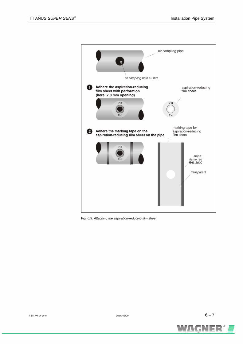
TITANUS SUPER·SENS® Installation Pipe System
TSS_06_A-en-e Data: 02/09 6 – 7
Fig. 6.3: Attaching the aspiration-reducing film sheet

Installation Pipe System TITANUS SUPER·SENS®
6 – 8 Data: 02/09 TSS_06_A-en-e
6.3 Ceiling lead through
Fig. 6.4: To install the ceiling feed-through use the following steps:
Before gluing remove dirt and grease with the recommended cleaner.
Glue the hose connector to the corresponding T-piece with Tangit glue.
For each ceiling feed-through drill a hole of ∅ 13mm through the false ceiling.
Install the lead-through by first removing the nut, pushing the hose sleeve from the bottom through the bore hole and then re-placing and tightening the nut above the false ceiling.
Determine the required length and cut the air sampling hose. Attach the hose to the sleeve of the ceiling feed-through and the hose con-nector at the T-piece of the air sampling pipe. If necessary soften the hose ends with a hot air fan.
Stick the correct aspiration-reducing film sheet (according to pipe design guidelines) to the ceiling feed-through.

TITANUS SUPER·SENS® Installation Pipe System
TSS_06_A-en-e Data: 02/09 6 – 9
The aspiration-reducing film sheets are available in two colours. Depend-ing on the colour of the ceiling, either type AFW-x (pure white, RAL 9010) or type AF-x (papyrus white, RAL 9018) are used. On request, film sheets in special colours are produced.
The perforation of the aspiration-reducing film sheet must be placed ex-actly over the opening of the ceiling lead-through and the diameter of the hole in the film sheet must not be altered. To keep the gluing surface of the film sheet free of dust and grease, avoid any contact.
INSTRUCTION

Installation Pipe System TITANUS SUPER·SENS®
6 – 10 Data: 02/09 TSS_06_A-en-e
6.4 Monitoring in forced air flow systems (ventilation or climatic applications)
6.4.1 Detection at air inlets/outlets
If aspiration takes place in a forced air flow system (ventilator, climatic systems), the air sampling points must be positioned in the air flow. Place the air sampling points as shown in fig. 6.5.
Fig. 6.5: Positioning of air sampling point, depending on air speed
6.4.2 Detection in bypass systems For connection of air return refer to chapter 6.6 "Air Return".
Fig. 6.6: Positioning of air return, example of a climatic duct (bypass)
For the pipe design of TITANUS® in these areas see chapter 4.3.4 “Pipe Design for Forced Air Flow“.
INSTRUCTION

TITANUS SUPER·SENS® Installation Pipe System
TSS_06_A-en-e Data: 02/09 6 – 11
6.5 Filter
6.5.1 Installation of air filter, type LF-AD-x
110
90
Fig. 6. 7: Spacing for bore holes on base of air filter housing
Air Filter LF-AD-x 1. To fit the filter into the pipe system, use the two PG29 filter screw-
joints. 2. Fix these screw-joints in the same way as the pipe adapter. 3. When installing the filter, ensure that the direction of air flow is shown
at the side of the housing’s bottom part. 4. Screw the bottom part of the housing directly to the wall.
Installation Material Air Filter cylinder or flat-head screws – thread diameter: max. 4 mm – head diameter: 5 to 7 mm

Installation Pipe System TITANUS SUPER·SENS®
6 – 12 Data: 02/09 TSS_06_A-en-e
6.5.2 Mounting of the special filter type SF-400/650
elbow 45°
elbow 45°
clamptype NG 23
PVC-reducingscrew joints
clamptype NG 23
special filter for ADx and TITANUStype SF-650type SF-400
®
Fig. 6.8: Mounting of the special filter into the pipe system
Special filter SF-x 1. To install or un-install the special filter use the two PVC reducer screw joints at both filter ends.
2. Glue the reducer couplings into the pipe system. 3. When installing the special filter, note the flow direction shown on the
filter housing.
4. Clamp the special filter with a 45º elbow piece to the pipe system.
Installation material Special Filter PVC or ABS pipe fittings
– 45° elbows
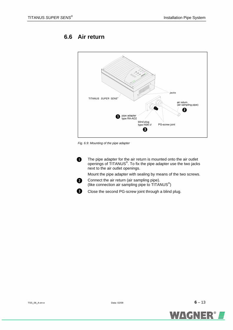
TITANUS SUPER·SENS® Installation Pipe System
TSS_06_A-en-e Data: 02/09 6 – 13
6.6 Air return
Fig. 6.9: Mounting of the pipe adapter
The pipe adapter for the air return is mounted onto the air outlet openings of TITANUS®. To fix the pipe adapter use the two jacks next to the air outlet openings. Mount the pipe adapter with sealing by means of the two screws.
Connect the air return (air sampling pipe). (like connection air sampling pipe to TITANUS®)
Close the second PG-screw joint through a blind plug.

Installation Pipe System TITANUS SUPER·SENS®
6 – 14 Data: 02/09 TSS_06_A-en-e
6.7 Noise suppressor
TITANUS®
PG-screw joint
noise suppressor
jacks
pipe adapter
blind plug
Fig. 6. 10: Mounting of noise suppressor
The pipe adapter for the noise suppressor is mounted onto the air outlet openings of TITANUS®. To fix the pipe adapter use the two jacks next to the air outlet openings. Mount the pipe adapter with sealing by means of the two screws.
Pass the pipe (∅ 25mm) through the opened feed-through in the protection grid and fix it with the existing pipe collar in the air outlet of TITANUS®. As the air return pipe fits exactly into the exit air open-ing, a tight fit is ensured.
Use the sound suppressor’s PG29 screw connection in order to connect the noise suppressor to the pipe.
When installing the absorbing duct, ensure that the direction of air flow is shown at the side of the housing’s bottom part.
Screw the bottom part of the housing directly to the wall.
Close the second PG-screw joint through a blind plug.
Installation material Noise suppressor cylinder or flat-head screws – thread diameter: max. 4 mm – head diameter: 5 to 7 mm

TITANUS SUPER·SENS® Installation Pipe System
TSS_06_A-en-e Data: 02/09 6 – 15
6.8 3-Way ball valve
air fi lter(option)
connector
pipe sys tem
compressed air
connector
scheme of the ball valve:
position 0° position 90° position 180°
connector air sampling smoke
detectio n system3-way sleeve ball valve
(option)type 3MKH
(max.16 bar)
18 0°
0°
90°
A
A B
C
A B
C
A B
C
B C
TITANUS®
Fig. 6.11: Montage des 3-Wege-Kugelhahns
The ball valve is used for blowing through with compressed air (prefera-bly) or pressed air1F
2. Switching occurs between detection (position 0º) and blow-through (position 180º). Connect the ball valve to the pipe system via reducing screw-joints.
Connections During installation, ensure that the correct connections are made (see diagram in fig. 6.11):
connect the air sampling pipe system to C. connect TITANUS ® to A or B and the compressed/pressed air to the remaining connection.
2 Pressed air is compressed, non-purified surround air, containing humidity. Compressed air
is purified and de-humidified. If TITANUS ® and the pipe system are located in areas below freezing, compressed air must be used for blow-through.

Installation Pipe System TITANUS SUPER·SENS®
6 – 16 Data: 02/09 TSS_06_A-en-e
The following steps should be taken for the blow-through process: 1. Connect the compressed air supply (compressor or mobile blow-
through device) for the blow-through of the pipes to the 3-way sleeve ball valve via the quick-acting coupling sleeve.
2. Separate the pipes to be blown through from the relevant device via the 3-way ball valve by re-setting the ball valve from operating position 0º to 180º (see fig. 6.11).
3. Manually blow the pipe system through for 10 seconds. 4. Set the ball valve to 90°. In this position the device is neither con-
nected to the pipe system nor the pressed or compressed air supply. Wait for about 20 seconds so that the dust and dirt disturbed in the pipe system can settle and not be aspirated by the smoke detection system.
5. Re-connect the blown-through pipes with the device within the next 10 second by re-positioning the ball valve to 0º.
A single blow-through process must be completed in 50 seconds. If a blow-through process is carried out within this time and the device re-connected with the pipe system, the fault alarm “air-flow sensor module fault” is not activated. If another blow-through process is necessary, the above process must be repeated at the earliest after 120 seconds.
INSTRUCTION

TITANUS SUPER·SENS® Installation Pipe System
TSS_06_A-en-e Data: 02/09 6 – 17
6.8 Steam trap
Fig. 6.12: Installation of steam trap to pipe system
Install the steam trap at the lowest point of the pipe system before the air filter and TITANUS® and fasten it with PG screw joints
Two 45º elbows are required on each connection end for the installation of the steam trap to the pipe system.
Connection When installing the steam trap, note the direction of air flow (see arrow on housing of steam trap). 1. Prepare the pipe system with two 45° elbows at each end of the
steam trap and connect it to the PG screw joints. 1. Additionally, secure the steam trap with two screws and the support.
INSTRUCTION

Installation Pipe System TITANUS SUPER·SENS®
6 – 18 Data: 02/09 TSS_06_A-en-e
6.9 Test adapter
Fig. 6.13: Mounting of the test adapter at the pipe system
The test adapter is glued into the pipe system close to the air sampling system. It must always be closed during normal operation and is only opened for repair and maintenance in order to introduce test gas or smoke.
After testing the detector module in the smoke detection system and the alarm relay, the test adapter must be closed again in order to avoid a possible air flow fault!
ATTENTION

TITANUS SUPER·SENS® Commissioning
TSS_07_A-en-e Data: 02/09 7 – 1
7 Commissioning
For a later verification of the air flow value register the commissioning temperature, air pressure and height above sea level in the commission-ing protocol.
Check of Settings Before the commissioning check the settings of TITANUS® (chapter 5.3 "Settings"). Then, connect TITANUS® to the power supply.
After max. 4 minutes the detector head of TITANUS® is ready for opera-tion.
Fig. 7.1: Check for tightness
For the commissioning of TITANUS SUPER · SENS® install the complete pipe system and connect it.
Check Verify if... 1. the pipe system is correctly attached to the pipe connector of
TITANUS®. 2. all pipe fittings are glued and the pipe system is airtight. 3. the air sampling points are fitted with the correct aspiration-reducing
film sheets. After the adjustment of the air flow sensor (chapter 7.1 "Adjustment Air Flow Sensor") modifications are not allowed anymore. If modifications are effected later on the air flow sensor is to be re-adjusted.
INSTRUCTION
INSTRUCTION
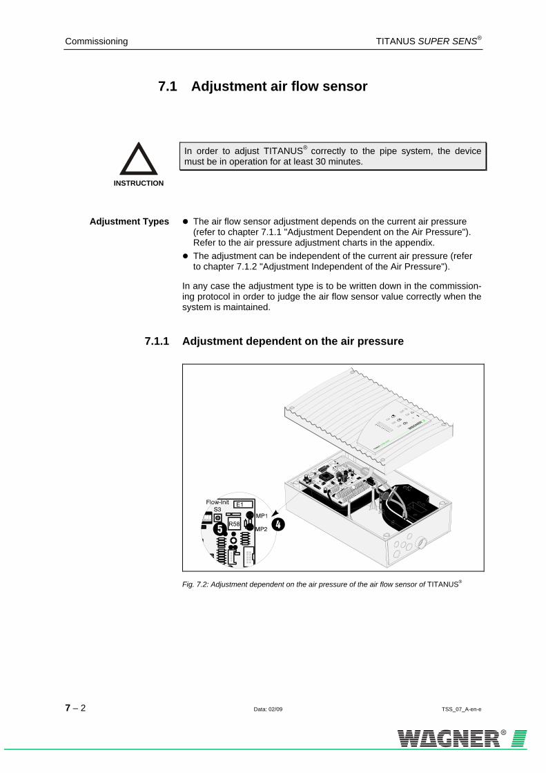
Commissioning TITANUS SUPER·SENS®
7 – 2 Data: 02/09 TSS_07_A-en-e
7.1 Adjustment air flow sensor
In order to adjust TITANUS® correctly to the pipe system, the device must be in operation for at least 30 minutes.
Adjustment Types The air flow sensor adjustment depends on the current air pressure
(refer to chapter 7.1.1 "Adjustment Dependent on the Air Pressure"). Refer to the air pressure adjustment charts in the appendix.
The adjustment can be independent of the current air pressure (refer to chapter 7.1.2 "Adjustment Independent of the Air Pressure").
In any case the adjustment type is to be written down in the commission-ing protocol in order to judge the air flow sensor value correctly when the system is maintained.
7.1.1 Adjustment dependent on the air pressure
Fig. 7.2: Adjustment dependent on the air pressure of the air flow sensor of TITANUS®
INSTRUCTION

TITANUS SUPER·SENS® Commissioning
TSS_07_A-en-e Data: 02/09 7 – 3
For the adjustment dependent on the air pressure of the air flow sensor a barometer 0F
1 is necessary. Follow the steps below:
Determine the height above sea level of the mounting location of the air sampling smoke detection system and register the value in the commissioning protocol.
Measure the air pressure by means of the pocket barometer and register the value in the commissioning protocol.
Determine the adjustment value for the air flow sensor according to the air pressure adjustment charts (refer to appendix) and register the value in the commissioning protocol. Pay attention that the ad-justment chart corresponds to the project planning of the pipe sys-tem.
Connect the measuring device to the test jacks MP1 (+), MP2 (-) (re-fer to 0HFig. 7.2). Pay attention to the polarity. Choose the "V-DC"-range of the measuring device. The standard voltage at the measur-ing points is 2.5 V.
Set the trimming potentiometer R58 to the determined value of the air pressure adjustment chart by means of a small screw driver. A tolerance of ± 100 mV is allowed.
Proceed according to chapter 7.1.2 "Adjustment Independent of the Air Pressure".
1 Recommendation: digital precision pocket barometer GPB 1300, Greisinger electronic GmbH

Commissioning TITANUS SUPER·SENS®
7 – 4 Data: 02/09 TSS_07_A-en-e
7.1.2 Adjustment independent of the air pressure
Fig. 7.3: Adjustment independent of the air pressure of the air flow sensor of TITANUS®
In order to adjust the air flow sensor independently of the air pressure press the Flow-Init-button (S3) on the base board of TITANUS® (refer to 1HFig. 7.3).
• After having pressed the button close the housing of TITANUS®. • Fix the housing top by means of the screws. • Verify if the housing lid is fixed tightly.
The learning phase of TITANUS® is about 5 minutes. During this phase the operating-LED flashes and changing of the air flow are not allowed. After the initialization the operating-LED lights permanently and the air flow sensor has determined its current value for the connected pipe sys-tem.

TITANUS SUPER·SENS® Commissioning
TSS_07_A-en-e Data: 02/09 7 – 5
7.2 Detector head and alarm transmission
Trigger the alarm of the smoke detector and check the transmission to the central fire panel as follows: 1. Spray test aerosol either into the first air sampling point or into the
test adapter of TITANUS®. 2. Follow the steps in the table.
Check to see if... If this is not the case...
the air sampling smoke detection system displays an alarm.
1. verify that the display board is connected. 2. the air sampling system is damaged. 3. exchange the detector head.
the alarm signal is transmitted to the central fire panel and on the corresponding line.
1. check the transmission cables.
Record all tested data in the inspection protocol.
7.3 Air Flow Monitoring
Pipe Fracture Verify the detection of pipe fractures: 1. Loosen the connection between pipe and TITANUS® or open the test
adapter. 2. Verify if the fault display of the air sampling smoke detection lights. 3. Check optionally the data of the air flow sensor by means of the diag-
nostic device and a PC or laptop. 4. Register the result in the commissioning protocol.
Blockage Verify the detection of blockages: 1. Close the necessary number of air sampling points by means of adhe-
sive tape according to the project planning of the air flow monitoring. 2. Verify if the fault display of the air sampling smoke detection system
lights. 3. Check optionally the data of the air flow sensor by means of the diag-
nostic device and a PC or laptop. 1. Register the result in the commissioning protocol.
INSTRUCTION

Commissioning TITANUS SUPER·SENS®
7 – 6 Data: 02/09 TSS_07_A-en-e
Trouble Shooting If faults in the air flow are not correctly detected by the device do the fol-lowing: Check to see if... 1. all air sampling points are free. 2. the pipe system has fractures or cracks. 3. all pipe connections are tight. 4. the ventilator is unblocked. 5. the correct aspiration-reducing film sheets have been used.
If no faults are detected the functionality of TITANUS® or the air flow sen-sor is checked by means of the testing pipe or through the diagnostic evaluation (refer to chapter 7.5 "Operational Check of TITANUS® ").
7.4 Fault signal transmission
The following steps can only be effected 5 minutes after having triggered the air flow adjustment according to chapter 7.1 "Adjustment of the Air Flow Sensor".
1. Check the fault signal transmission. Check the air flow monitoring (according to the following section) to see if the fault is still indicated at TITANUS® and, if necessary, at the central fire panel.
INSTRUCTION

TITANUS SUPER·SENS® Commissioning
TSS_07_A-en-e Data: 02/09 7 – 7
7.5 Operational check of TITANUS®
If it is not possible to adjust TITANUS® check the functionality by means of the testing pipe and a digital manometer or the diagnostic device. Dur-ing this check TITANUS® is to be operated.
7.5.1 Preparation of the operational check
Set the switches on the base board (refer to 2HFig. 7.3) according to the following table:
Switch base board air flow monitoring
Switch S2
Contact A (1) Contact A (1) Contact A (1) Contact A (1)
off on off off
delay period 0.5 min
activating threshold large
Switch base board detector sensitivity
Switch S2
Contact E (5) Contact F (6) Contact E (7) Contact F (8)
on off off on
alarm/delay period 10 s
response sensitivity (HA) 0.1%/m
Switch base board
fault signal Switch S2 Contact J (10)
off
non-latched
Remove the pipe system from TITANUS®.
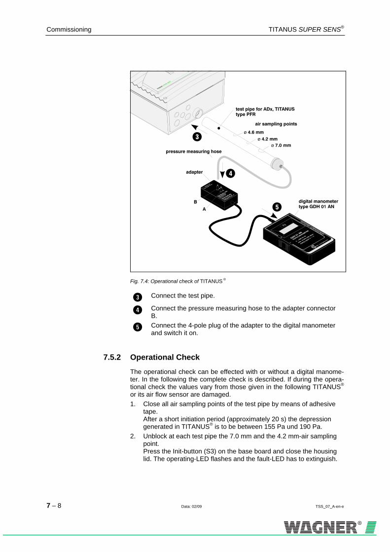
Commissioning TITANUS SUPER·SENS®
7 – 8 Data: 02/09 TSS_07_A-en-e
Fig. 7.4: Operational check of TITANUS ®
Connect the test pipe.
Connect the pressure measuring hose to the adapter connector B.
Connect the 4-pole plug of the adapter to the digital manometer and switch it on.
7.5.2 Operational Check
The operational check can be effected with or without a digital manome-ter. In the following the complete check is described. If during the opera-tional check the values vary from those given in the following TITANUS® or its air flow sensor are damaged. 1. Close all air sampling points of the test pipe by means of adhesive
tape. After a short initiation period (approximately 20 s) the depression generated in TITANUS® is to be between 155 Pa und 190 Pa.
2. Unblock at each test pipe the 7.0 mm and the 4.2 mm-air sampling point. Press the Init-button (S3) on the base board and close the housing lid. The operating-LED flashes and the fault-LED has to extinguish.

TITANUS SUPER·SENS® Commissioning
TSS_07_A-en-e Data: 02/09 7 – 9
3. Close the 4.2 mm-air sampling points of the test pipe by means of adhesive tape after the learning phase. After approximately 75 s the fault display of TITANUS® has to start flashing.
4. Open the 4.2 mm-air sampling points. The fault display of TITANUS® has to extinguish again.
5. Open the 4.6 mm-air sampling points at the testing pipe. After about 85 s the fault display of TITANUS® has to start flashing.
6. Close the 4.6 mm-air sampling points again. The fault display of TITANUS® has to extinguish again.
For the operational check the diagnostic device or the connection cable with the diagnostic interface can be used as an option. The following steps are to be considered:
Diagnostic device Connection cable with diagnostic interface
1. The diagnostic device is connected to a PC 1F
1 (COM1, COM2) 1. The connection cable is connected to a
PC 2F
1 (COM1, COM2)
2. The diagnostic program is started.
3. The receiving-LED of the diagnostic de-vice is put over the infrared-diagnostic LED of TITANUS® and is operated through pressing the ON-button.
3. The connection cable is connected to the terminals X 2.16 und X 2.17 with its remaining end (2 wires).
3a. The display of the diagnostic device is flashing every second as long as the device is put over the infrared-LED, which means as long as data are transmitted.
4. The current data of TITANUS SUPER · SENS ® are visualized on the PC-screen.
After a fault has been eliminated the settings of switch S1 are to be reset to the original state. The commissioning is to be repeated from chapter 7.1 "Air Flow Sensor Adjustment" on.
1 PC with serial interface and WIN 95

Commissioning TITANUS SUPER·SENS®
7 – 10 Data: 02/09 TSS_07_A-en-e

8 Maintenance
8.1 Visual Check
Check to see if the pipe system is mounted tightly, undamaged and easily accessible. the air sampling points of the pipe system are unblocked. the air sampling pipe and the connection cable are connected tightly. the device support is fastened properly – if installed. the air sampling smoke detection system is damaged-
8.2 Smoke Detector and Alarm Transmis-sion
Proceed according to chapter 7.2 "Detector Head and Alarm Transmis-sion". In addition, check the detector head through visual check for exter-nal dirt and, if necessary, exchange it. Pay attention to the drift display at the diagnostic device.
8.3 Pipe System
In areas where dust particles or icings may occur check the pipe system and the air sampling points for blockage. If necessary, blow-out the pipe system and the air sampling points by means of compressed air. Use prophylactic ally a transportable compressed air bottle (blowing-out sys-tem) or the installed manual blowing-out system. Before the pipe system is blown-out disconnect TITANUS® from the pipe system in order to avoid damaging the air flow sensor.
In order to adjust TITANUS® correctly to the pipe system, the device must be in operation for at least 30 minutes.
ATTENTION
INSTRUCTION

8.4 Exchange of the Detector Head
Fig. 8.1: Exchange of the detector head
Loosen the four screws on the housing lid of TITANUS® and lift it carefully.
Pull the connection cable of the display board off the base board. Now remove the housing lid.
Pull the two hoses of the air flow sensor filter off the detector head.
Loosen the ribbon cable X8.
Loosen the four screws of the detector head support.
Pull the detector head out of the tip jack of the air inlet and re-
move the head ( ).
Place the new detector head in the housing so that it is exactly attached to the tip jack of the air inlet.
Fix the four screws of the detector head support.
Attach the ribbon cable X8.
Fix the two hoses of the air flow sensor filter at the detector head.
Attach the cable of the display board to the base board.
Replace the housing lid and fix it by the four screws.

In order to adjust TITANUS® correctly to the pipe system, the device must be in operation for at least 30 minutes.
INSTRUCTION

8.5 Exchange of the air flow sensor filter
Fig. 8.2: Exchange of the air flow sensor filter
Open TITANUS® by loosening the four screws on the housing lid. Then open the lid carefully.
Detach the cable of the display board from the base board (X6). Now the lid can be removed.
Detach both hose ends from the air flow sensor filter and take
it out .
Fix again both hose ends onto the new air flow sensor filter.
Fix the cable of the display board onto the base board.
Close the housing lid and fasten the four screws tightly.
Avoid mechanical load on the air flow sensor filter!.
ATTENTION

8.4 Changing the air filter LF-AD –x
1
2
primary filter
coarse dust filter
Fine dust filter
air sampling pipe
Air flow direction
air filter for Adx and TITANUS, type LF-AD
Fig. 8.3: change the filter inserts
To clean or change the filter inserts, carry out the following steps (see fig. 8.4):
1 Loosen the four screws and remove the housing lid.
2 Remove the filter inserts and check how soiled they are. The inserts can be cleaned if there is a small amount of soiling and must be re-placed if soiling is heavy.
3 Carefully clean the inside of the housing from any dust. Replace the cleaned or replaced filter inserts in the correct sequence, which is shown on the instruction label of the housing floor.
4 Replace and screw down the housing lid.
In environments with a high level of fine-grade dust, three optional fine dust filters can be used in addition.
Opening the housing lid of the air filter LF-AD-x causes an air flow fault in TITANUS®.
TIP
INSTRUCTION

8.7 Changing special air filter SF-400/650
®
1a1b
3
2
air sampling pipe
Air flow direction
special filter Adx & TITANUStype SF-400type SF-650
Fig. 8.4: Exchange of filter element
To change the filter insert follow these steps:
1 Loosen the two PVC reducing couplings on the special filter and remove it .
2 Remove the two screw-in plugs on the filter housing.
3 Remove the filter insert from the housing and replace with a new one.
4 Replace the two screw-in plugs in the filter housing.
5 Re-insert the special filter into the pipe system and fix it firmly in place with PVC reducing couplings.
When installing the special filter it is important to note the direction of air flow!
Opening the housing lid of the special air filter causes an air flow fault in TITANUS®.
INSTRUCTION
INSTRUCTION

8.8 Check of the Air Flow Sensor Adjustment
Close the housing of the air sampling smoke detection system before the air flow sensor adjustment check. Check the air flow sensor value by means of the diagnostic device.
Independent of Air Pressure The standard ranges of the air flow variations for the small threshold are
± 90%, for the medium threshold ± 50% and for the large threshold ± 25%. These values already contain temperature and air pressure varia-tions if the sensor adjustment is dependent on the air pressure (for the adjustment type refer to the commissioning protocol).
Dependent on Air Pressure If the sensor adjustment is independent of the air pressure air pressure
variations can considerably increase these values which should not lead to a fault signal.
Consider that the measured value permanently changes due to tempera-ture and air pressure variations.
Variations If the measured value is not within the range of the allowed tolerances
the air pressure varies and another fault is present. In this case check the pipe system for tightness and blockage of the air sampling points (refer to chapter 7.3, section "Trouble Shooting"). If this check leads to no nega-tive results check the ventilator fan in the air sampling smoke detection system for soiling and exchange the air flow sensor filter if required (refer also to chapter 8.8 "Exchange of the Air Flow Sensor Filter"). If the faults are still present verify the air flow monitoring electronics by connecting a test pipe to the device and by re-adjusting the air flow. If the air flow monitoring system is damaged only authorized personnel is allowed to exchange it!
If the pipe network has been modified during the trouble shooting or if the air flow sensor filter has been exchanged re-adjust the air flow.
Register the adjustment type (dependent on air pressure or not) and, if required, the values of the air pressure, the height above sea level and the set voltage at MP1 / MP2 in the commissioning protocol.
INSTRUCTION
ATTENTION
INSTRUCTION

8.9 Air flow monitoring
Proceed according to chapter 7.3 "Air Flow Monitoring".
8.10 Fault signal transmission
Proceed according to chapter 7.4 "Fault Signal Transmission".
8.11 Maintenance intervals
Maintenance includes regular inspection. The air sampling smoke detec-tion systems are checked during commissioning and then every three months (quarterly). Every fourth inspection includes additional checks which leads to the following distinction:
quarterly check inspection annual check maintenance + 4th annual inspection
Type of Check Measure Further Information in Chap-ter
inspection visual check
detector head and alarm trans-mission (1 x per group)
check of pipe system
air flow sensor adjustment
fault signal transmission (1 x per group)
if necessary air filter check
8.1
8.2
8.3
8.4
7.4
maintenance + 4th annual inspection
visual check
detector head and alarm trans-mission
check of pipe system
air flow sensor adjustment
fault signal transmission
air flow monitoring
exchange of the air flow sensor filter
8.1
8.2
8.3
8.4
7.4
7.5
8.5
The filter of the air flow sensors is to be exchanged regularly!
INSTRUCTION

Appendix
Air Pressure Adjustment Tables
Projection Tables
System Product List
Certificate of Approval of Components and Systems
EMC Declaration of Conformity
Inspection Protocol
Glossary
Conformity certification pursuant to EU


Report 60017WGR Stammhaus
7/23/09
wendler1page
System Product List
order no. description unit
TITANUS SUPER·SENS/a, DNL-Delivery Transaction--
Air Sampling Smoke Detection Systems
AD-05-0800 air sampl. smoke detection system rev. a
type TITANUS SUPER·SENS /a
pc.
<P> <Z><><2>
AD-05-0810 air sampl. smoke detection system rev. a
type TITANUS SUPER·SENS R /a
pc.
<P> <Z><><2>
AD-05-0820 air sampl. smoke detection system rev.a
type TITANUS SUPER·SENS G /a
pc.
<P> <Z><><2>
AD-05-0830 air sampl. smoke detection system rev. a
type TITANUS SUPER·SENS RS /a
pc.
<P> <Z><><2>
AD-10-1045 front film sheet TI.SUPER·SENS/a,Siemens
type FSBT-SUPER·SENS/a
pc.
<P> <Z><><2>
<0>=Generic purch. item, <1>=Purch. item fixed vendor, <2>=Proprietary develop. (ANT/develop.), <3>=in-house prod. (ANT/develop./prod.), <4>=Compon. 140l Fl.
<AM>=discontinued model, <Z> = approved, <P>=compulsory purchase, purchase only via WAGNER head office, <L>=compulsory supplier, purchase via fixed supplier

Report 60017WGR Stammhaus
7/23/09
wendler2page
System Product List
order no. description unit
TITANUS SUPER·SENS/a, DNL-Delivery Transaction--
Accessories
AD-05-0270 remote display unit in wall housing
type PAG3-TITANUS
pc.
<P> <Z><><2>
AD-05-0600 diagnostic device for AD and TITANUS
type DIAG+
pc.
<P> <Z><><2>
AD-05-0620 diagnostic-interface
type IF-DIAG+
pc.
<P> <Z><><2>
AD-05-0900 cable entry kit
type KES_PG11
pc.
<P> <Z><><2>
AD-10-0225 front film sheet for PAG-TITANUS, Wagner
type FW-PAG
pc.
<P> <Z><><2>
AD-10-0550 test pipe for air sampling systems
type DIAG-Pipe
pc.
<P> <Z><><0>
<0>=Generic purch. item, <1>=Purch. item fixed vendor, <2>=Proprietary develop. (ANT/develop.), <3>=in-house prod. (ANT/develop./prod.), <4>=Compon. 140l Fl.
<AM>=discontinued model, <Z> = approved, <P>=compulsory purchase, purchase only via WAGNER head office, <L>=compulsory supplier, purchase via fixed supplier

Report 60017WGR Stammhaus
7/23/09
wendler3page
System Product List
order no. description unit
TITANUS SUPER·SENS/a, DNL-Delivery Transaction--
Spare Parts
01-45-5295 housing for TITANUS SUPER·SENS/a
type KG-TSS/a
pc.
<P> <Z><><0>
01-45-5297 cap nuts
type CN-TSS/a<P> <Z><><0>
02-70-0640 radial ventilator f. TITANUS SUPERSENS/a
type RG125-19/12N-TSS/a
pc.
<P> <Z><><0>
09-20-5980 display board TITANUS 3000/SUPER·SENS
type E598 (with bargraph display)
pc.
<P> <Z><><2>
09-20-5985 exchange set
type DB-IR-1 (pu=1 pc.)
pc.
<P> <Z><><3>
09-20-5995 switch power supply for remote display
type E599.2
pc.
<P> <Z><><2>
09-20-6030 base board TITANUS SUPER·SENS
type E603
pc.
<P> <Z><><2>
09-20-6045 base board TITANUS SUPER·SENS
type E603-G
pc.
<P> < ><><2>
10-60-0695 operat.device reset and discon. button
type RTT-1, 19"
pc.
<P> <Z><><2>
AD-05-0265 housing for remote display TITANUS
type GPA-3000/SUPERSENS
pc.
<P> <Z><><0>
AD-05-0630 board for reset and disconnecting button
type RTT-1
pc.
<P> <Z><><2>
<0>=Generic purch. item, <1>=Purch. item fixed vendor, <2>=Proprietary develop. (ANT/develop.), <3>=in-house prod. (ANT/develop./prod.), <4>=Compon. 140l Fl.
<AM>=discontinued model, <Z> = approved, <P>=compulsory purchase, purchase only via WAGNER head office, <L>=compulsory supplier, purchase via fixed supplier

Report 60017WGR Stammhaus
7/23/09
wendler4page
System Product List
order no. description unit
TITANUS SUPER·SENS/a, DNL-Delivery Transaction--
AD-10-0275 front plate for PAW-TITANUS, Wagner
type FPW3-PA
pc.
<P> <Z><><2>
AD-10-0410 air filter, for air flow sensor
type LF-AWM3100V
pc.
<P> <Z><><2>
AD-10-0435 sealing kit for detector head
type SL-DK (VE=10 sets)<P> <Z><><0>
AD-10-4110 detector head TITANUS SUPERSENS/a
type TSS/a-DK 0.02
pc.
<P> <Z><><2>
AD-10-4120 detector head TITANUS SUPERSENS/a clean
type TSS/a-DKR 0.01
pc.
<P> <Z><><2>
AD-10-4130 detector head TITANUS SUPERSENS/a galvan
type TSS/a-DKG 0.02
pc.
<P> <Z><><2>
AD-10-4140 detector head TITANUS SUPERSENS/a RS
type TSS/a-DKRS 0.006
pc.
<P> <Z><><2>
AD-10-4660 connecting cable
type CC-NU
pc.
<P> <Z><><2>
<0>=Generic purch. item, <1>=Purch. item fixed vendor, <2>=Proprietary develop. (ANT/develop.), <3>=in-house prod. (ANT/develop./prod.), <4>=Compon. 140l Fl.
<AM>=discontinued model, <Z> = approved, <P>=compulsory purchase, purchase only via WAGNER head office, <L>=compulsory supplier, purchase via fixed supplier

Air Pressure Adjustment Chart TITANUS SUPER · SENS ®
Adjustment TITANUS SUPER · SENS Equipment Monitoring(opening in percent: 15% up to 24%)
height above sea level Air Pressure [hPa] at a Height of
0 973 978 983 988 993 998 1003 1008 1013 1018 1023 1028 1033 1038 104350 967 972 977 982 987 992 997 1002 1007 1012 1017 1022 1027 1032 1037100 961 966 971 976 981 986 991 996 1001 1006 1011 1016 1021 1026 1031150 954 959 964 969 974 979 984 989 994 999 1004 1009 1014 1019 1024200 948 953 958 963 968 973 978 983 988 993 998 1003 1008 1013 1018250 942 947 952 957 962 967 972 977 982 987 992 997 1002 1007 1012300 936 941 946 951 956 961 966 971 976 981 986 991 996 1001 1006350 930 935 940 945 950 955 960 965 970 975 980 985 990 995 1000400 924 929 934 939 944 949 954 959 964 969 974 979 984 989 994450 918 923 928 933 938 943 948 953 958 963 968 973 978 983 988500 912 917 922 927 932 937 942 947 952 957 962 967 972 977 982550 906 911 916 921 926 931 936 941 946 951 956 961 966 971 976600 900 905 910 915 920 925 930 935 940 945 950 955 960 965 970650 894 899 904 909 914 919 924 929 934 939 944 949 954 959 964700 888 893 898 903 908 913 918 923 928 933 938 943 948 953 958750 882 887 892 897 902 907 912 917 922 927 932 937 942 947 952800 877 882 887 892 897 902 907 912 917 922 927 932 937 942 947850 871 876 881 886 891 896 901 906 911 916 921 926 931 936 941900 865 870 875 880 885 890 895 900 905 910 915 920 925 930 935950 860 865 870 875 880 885 890 895 900 905 910 915 920 925 9301000 854 859 864 869 874 879 884 889 894 899 904 909 914 919 9241050 848 853 858 863 868 873 878 883 888 893 898 903 908 913 9181100 843 848 853 858 863 868 873 878 883 888 893 898 903 908 9131150 837 842 847 852 857 862 867 872 877 882 887 892 897 902 9071200 832 837 842 847 852 857 862 867 872 877 882 887 892 897 9021250 827 832 837 842 847 852 857 862 867 872 877 882 887 892 8971300 821 826 831 836 841 846 851 856 861 866 871 876 881 886 8911350 816 821 826 831 836 841 846 851 856 861 866 871 876 881 8861400 810 815 820 825 830 835 840 845 850 855 860 865 870 875 8801450 805 810 815 820 825 830 835 840 845 850 855 860 865 870 8751500 800 805 810 815 820 825 830 835 840 845 850 855 860 865 8701550 795 800 805 810 815 820 825 830 835 840 845 850 855 860 8651600 789 794 799 804 809 814 819 824 829 834 839 844 849 854 8591650 784 789 794 799 804 809 814 819 824 829 834 839 844 849 8541700 779 784 789 794 799 804 809 814 819 824 829 834 839 844 8491750 774 779 784 789 794 799 804 809 814 819 824 829 834 839 8441800 769 774 779 784 789 794 799 804 809 814 819 824 829 834 8391850 764 769 774 779 784 789 794 799 804 809 814 819 824 829 8341900 759 764 769 774 779 784 789 794 799 804 809 814 819 824 8291950 754 759 764 769 774 779 784 789 794 799 804 809 814 819 8242000 749 754 759 764 769 774 779 784 789 794 799 804 809 814 8192050 744 749 754 759 764 769 774 779 784 789 794 799 804 809 8142100 739 744 749 754 759 764 769 774 779 784 789 794 799 804 8092150 734 739 744 749 754 759 764 769 774 779 784 789 794 799 8042200 729 734 739 744 749 754 759 764 769 774 779 784 789 794 7992250 725 730 735 740 745 750 755 760 765 770 775 780 785 790 7952300 720 725 730 735 740 745 750 755 760 765 770 775 780 785 7902350 715 720 725 730 735 740 745 750 755 760 765 770 775 780 7852400 710 715 720 725 730 735 740 745 750 755 760 765 770 775 780
Titanus SS [V] 1,09 1,27 1,44 1,62 1,80 1,97 2,15 2,32 2,50 2,68 2,85 3,03 3,20 3,38 3,56
released: dated: 03.08.2009

Air Pressure Adjustment Chart TITANUS SUPER · SENS ®
Adjustment TITANUS SUPER · SENS Room Monitoring (I-Shape Pipe System)(opening in percent: 19%)
height abovesea level Air Pressure [hPa] at a Height of
0 973 978 983 988 993 998 1003 1008 1013 1018 1023 1028 1033 1038 104350 967 972 977 982 987 992 997 1002 1007 1012 1017 1022 1027 1032 1037100 961 966 971 976 981 986 991 996 1001 1006 1011 1016 1021 1026 1031150 954 959 964 969 974 979 984 989 994 999 1004 1009 1014 1019 1024200 948 953 958 963 968 973 978 983 988 993 998 1003 1008 1013 1018250 942 947 952 957 962 967 972 977 982 987 992 997 1002 1007 1012300 936 941 946 951 956 961 966 971 976 981 986 991 996 1001 1006350 930 935 940 945 950 955 960 965 970 975 980 985 990 995 1000400 924 929 934 939 944 949 954 959 964 969 974 979 984 989 994450 918 923 928 933 938 943 948 953 958 963 968 973 978 983 988500 912 917 922 927 932 937 942 947 952 957 962 967 972 977 982550 906 911 916 921 926 931 936 941 946 951 956 961 966 971 976600 900 905 910 915 920 925 930 935 940 945 950 955 960 965 970650 894 899 904 909 914 919 924 929 934 939 944 949 954 959 964700 888 893 898 903 908 913 918 923 928 933 938 943 948 953 958750 882 887 892 897 902 907 912 917 922 927 932 937 942 947 952800 877 882 887 892 897 902 907 912 917 922 927 932 937 942 947850 871 876 881 886 891 896 901 906 911 916 921 926 931 936 941900 865 870 875 880 885 890 895 900 905 910 915 920 925 930 935950 860 865 870 875 880 885 890 895 900 905 910 915 920 925 9301000 854 859 864 869 874 879 884 889 894 899 904 909 914 919 9241050 848 853 858 863 868 873 878 883 888 893 898 903 908 913 9181100 843 848 853 858 863 868 873 878 883 888 893 898 903 908 9131150 837 842 847 852 857 862 867 872 877 882 887 892 897 902 9071200 832 837 842 847 852 857 862 867 872 877 882 887 892 897 9021250 827 832 837 842 847 852 857 862 867 872 877 882 887 892 8971300 821 826 831 836 841 846 851 856 861 866 871 876 881 886 8911350 816 821 826 831 836 841 846 851 856 861 866 871 876 881 8861400 810 815 820 825 830 835 840 845 850 855 860 865 870 875 8801450 805 810 815 820 825 830 835 840 845 850 855 860 865 870 8751500 800 805 810 815 820 825 830 835 840 845 850 855 860 865 8701550 795 800 805 810 815 820 825 830 835 840 845 850 855 860 8651600 789 794 799 804 809 814 819 824 829 834 839 844 849 854 8591650 784 789 794 799 804 809 814 819 824 829 834 839 844 849 8541700 779 784 789 794 799 804 809 814 819 824 829 834 839 844 8491750 774 779 784 789 794 799 804 809 814 819 824 829 834 839 8441800 769 774 779 784 789 794 799 804 809 814 819 824 829 834 8391850 764 769 774 779 784 789 794 799 804 809 814 819 824 829 8341900 759 764 769 774 779 784 789 794 799 804 809 814 819 824 8291950 754 759 764 769 774 779 784 789 794 799 804 809 814 819 8242000 749 754 759 764 769 774 779 784 789 794 799 804 809 814 8192050 744 749 754 759 764 769 774 779 784 789 794 799 804 809 8142100 739 744 749 754 759 764 769 774 779 784 789 794 799 804 8092150 734 739 744 749 754 759 764 769 774 779 784 789 794 799 8042200 729 734 739 744 749 754 759 764 769 774 779 784 789 794 7992250 725 730 735 740 745 750 755 760 765 770 775 780 785 790 7952300 720 725 730 735 740 745 750 755 760 765 770 775 780 785 7902350 715 720 725 730 735 740 745 750 755 760 765 770 775 780 7852400 710 715 720 725 730 735 740 745 750 755 760 765 770 775 780
Titanus SS [V] 1,24 1,39 1,55 1,71 1,87 2,03 2,18 2,34 2,50 2,66 2,82 2,97 3,13 3,29 3,45
released: dated: 03.08.2009
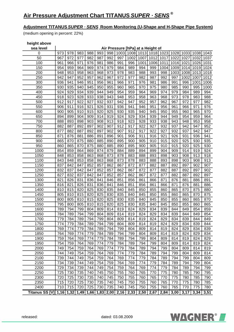
Air Pressure Adjustment Chart TITANUS SUPER · SENS ®
Adjustment TITANUS SUPER · SENS Room Monitoring (U-Shape and H-Shape Pipe System)(medium opening in percent: 22%)
height abovesea level Air Pressure [hPa] at a Height of
0 973 978 983 988 993 998 1003 1008 1013 1018 1023 1028 1033 1038 104350 967 972 977 982 987 992 997 1002 1007 1012 1017 1022 1027 1032 1037100 961 966 971 976 981 986 991 996 1001 1006 1011 1016 1021 1026 1031150 954 959 964 969 974 979 984 989 994 999 1004 1009 1014 1019 1024200 948 953 958 963 968 973 978 983 988 993 998 1003 1008 1013 1018250 942 947 952 957 962 967 972 977 982 987 992 997 1002 1007 1012300 936 941 946 951 956 961 966 971 976 981 986 991 996 1001 1006350 930 935 940 945 950 955 960 965 970 975 980 985 990 995 1000400 924 929 934 939 944 949 954 959 964 969 974 979 984 989 994450 918 923 928 933 938 943 948 953 958 963 968 973 978 983 988500 912 917 922 927 932 937 942 947 952 957 962 967 972 977 982550 906 911 916 921 926 931 936 941 946 951 956 961 966 971 976600 900 905 910 915 920 925 930 935 940 945 950 955 960 965 970650 894 899 904 909 914 919 924 929 934 939 944 949 954 959 964700 888 893 898 903 908 913 918 923 928 933 938 943 948 953 958750 882 887 892 897 902 907 912 917 922 927 932 937 942 947 952800 877 882 887 892 897 902 907 912 917 922 927 932 937 942 947850 871 876 881 886 891 896 901 906 911 916 921 926 931 936 941900 865 870 875 880 885 890 895 900 905 910 915 920 925 930 935950 860 865 870 875 880 885 890 895 900 905 910 915 920 925 9301000 854 859 864 869 874 879 884 889 894 899 904 909 914 919 9241050 848 853 858 863 868 873 878 883 888 893 898 903 908 913 9181100 843 848 853 858 863 868 873 878 883 888 893 898 903 908 9131150 837 842 847 852 857 862 867 872 877 882 887 892 897 902 9071200 832 837 842 847 852 857 862 867 872 877 882 887 892 897 9021250 827 832 837 842 847 852 857 862 867 872 877 882 887 892 8971300 821 826 831 836 841 846 851 856 861 866 871 876 881 886 8911350 816 821 826 831 836 841 846 851 856 861 866 871 876 881 8861400 810 815 820 825 830 835 840 845 850 855 860 865 870 875 8801450 805 810 815 820 825 830 835 840 845 850 855 860 865 870 8751500 800 805 810 815 820 825 830 835 840 845 850 855 860 865 8701550 795 800 805 810 815 820 825 830 835 840 845 850 855 860 8651600 789 794 799 804 809 814 819 824 829 834 839 844 849 854 8591650 784 789 794 799 804 809 814 819 824 829 834 839 844 849 8541700 779 784 789 794 799 804 809 814 819 824 829 834 839 844 8491750 774 779 784 789 794 799 804 809 814 819 824 829 834 839 8441800 769 774 779 784 789 794 799 804 809 814 819 824 829 834 8391850 764 769 774 779 784 789 794 799 804 809 814 819 824 829 8341900 759 764 769 774 779 784 789 794 799 804 809 814 819 824 8291950 754 759 764 769 774 779 784 789 794 799 804 809 814 819 8242000 749 754 759 764 769 774 779 784 789 794 799 804 809 814 8192050 744 749 754 759 764 769 774 779 784 789 794 799 804 809 8142100 739 744 749 754 759 764 769 774 779 784 789 794 799 804 8092150 734 739 744 749 754 759 764 769 774 779 784 789 794 799 8042200 729 734 739 744 749 754 759 764 769 774 779 784 789 794 7992250 725 730 735 740 745 750 755 760 765 770 775 780 785 790 7952300 720 725 730 735 740 745 750 755 760 765 770 775 780 785 7902350 715 720 725 730 735 740 745 750 755 760 765 770 775 780 7852400 710 715 720 725 730 735 740 745 750 755 760 765 770 775 780
Titanus SS [V] 1,16 1,32 1,49 1,66 1,83 2,00 2,16 2,33 2,50 2,67 2,84 3,00 3,17 3,34 3,51
released: dated: 03.08.2009

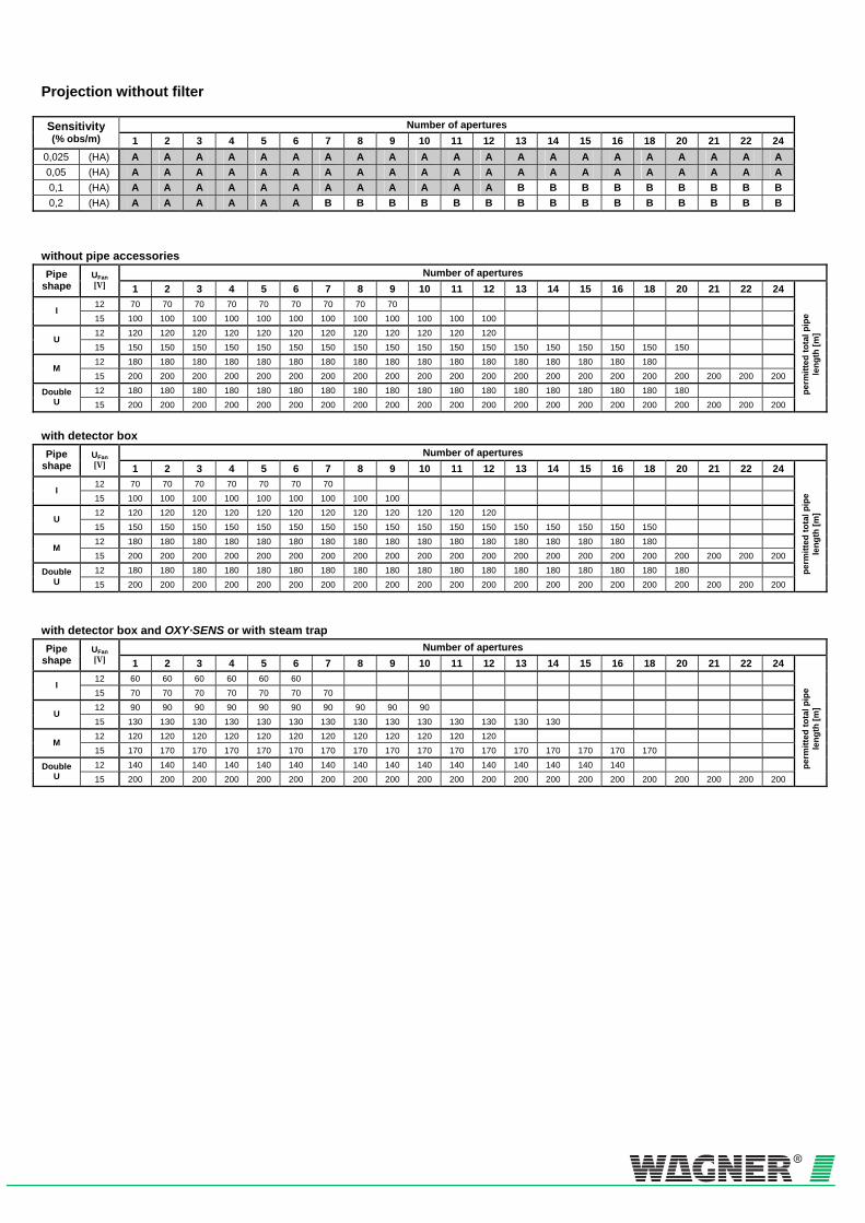
Projection without filter
Number of apertures Sensitivity (% obs/m) 1 2 3 4 5 6 7 8 9 10 11 12 13 14 15 16 18 20 21 22 24
0,025 (HA) A A A A A A A A A A A A A A A A A A A A A 0,05 (HA) A A A A A A A A A A A A A A A A A A A A A 0,1 (HA) A A A A A A A A A A A A B B B B B B B B B 0,2 (HA) A A A A A A B B B B B B B B B B B B B B B
without pipe accessories
Number of apertures Pipe shape
UFan [V] 1 2 3 4 5 6 7 8 9 10 11 12 13 14 15 16 18 20 21 22 24 12 70 70 70 70 70 70 70 70 70
I 15 100 100 100 100 100 100 100 100 100 100 100 100 12 120 120 120 120 120 120 120 120 120 120 120 120
U 15 150 150 150 150 150 150 150 150 150 150 150 150 150 150 150 150 150 150 12 180 180 180 180 180 180 180 180 180 180 180 180 180 180 180 180 180
M 15 200 200 200 200 200 200 200 200 200 200 200 200 200 200 200 200 200 200 200 200 200 12 180 180 180 180 180 180 180 180 180 180 180 180 180 180 180 180 180 180 Double
U 15 200 200 200 200 200 200 200 200 200 200 200 200 200 200 200 200 200 200 200 200 200
perm
itted
tota
l pip
e le
ngth
[m]
with detector box
Number of apertures Pipe shape
UFan [V] 1 2 3 4 5 6 7 8 9 10 11 12 13 14 15 16 18 20 21 22 24 12 70 70 70 70 70 70 70
I 15 100 100 100 100 100 100 100 100 100 12 120 120 120 120 120 120 120 120 120 120 120 120
U 15 150 150 150 150 150 150 150 150 150 150 150 150 150 150 150 150 150 12 180 180 180 180 180 180 180 180 180 180 180 180 180 180 180 180 180
M 15 200 200 200 200 200 200 200 200 200 200 200 200 200 200 200 200 200 200 200 200 200 12 180 180 180 180 180 180 180 180 180 180 180 180 180 180 180 180 180 180 Double
U 15 200 200 200 200 200 200 200 200 200 200 200 200 200 200 200 200 200 200 200 200 200
perm
itted
tota
l pip
e le
ngth
[m]
with detector box and OXY·SENS or with steam trap
Number of apertures Pipe shape
UFan [V] 1 2 3 4 5 6 7 8 9 10 11 12 13 14 15 16 18 20 21 22 24 12 60 60 60 60 60 60
I 15 70 70 70 70 70 70 70 12 90 90 90 90 90 90 90 90 90 90
U 15 130 130 130 130 130 130 130 130 130 130 130 130 130 130 12 120 120 120 120 120 120 120 120 120 120 120 120
M 15 170 170 170 170 170 170 170 170 170 170 170 170 170 170 170 170 170 12 140 140 140 140 140 140 140 140 140 140 140 140 140 140 140 140 Double
U 15 200 200 200 200 200 200 200 200 200 200 200 200 200 200 200 200 200 200 200 200 200
perm
itted
tota
l pip
e le
ngth
[m]

Projection with air filter LF-AD
Number of apertures Sensitivity (% obs/m) 1 2 3 4 5 6 7 8 9 10 11 12 13 14 15 16 18 20 21 22 24
0,025 (HA) A A A A A A A A A A A A A A A A A A A A A 0,05 (HA) A A A A A A A A A A A A A A A A A B B B B 0,1 (HA) A A A A A A A A A B B B B B B B B B B B B 0,2 (HA) A A A A B B B B B B B B B B B B B
without additional pipe accessories
Number of apertures Pipe shape
UFan [V] 1 2 3 4 5 6 7 8 9 10 11 12 13 14 15 16 18 20 21 22 24 12 70 70 70 70 70 70 70 70
I 15 100 100 100 100 100 100 100 100 100 100 12 120 120 120 120 120 120 120 120 120 120 120 120
U 15 150 150 150 150 150 150 150 150 150 150 150 150 150 150 150 150 150 150 12 180 180 180 180 180 180 180 180 180 180 180 180 180 180 180 180 180
M 15 200 200 200 200 200 200 200 200 200 200 200 200 200 200 200 200 200 200 200 200 200 12 180 180 180 180 180 180 180 180 180 180 180 180 180 180 180 180 180 180 Double
U 15 200 200 200 200 200 200 200 200 200 200 200 200 200 200 200 200 200 200 200 200 200
perm
itted
tota
l pip
e le
ngth
[m]
with detector box
Number of apertures Pipe shape
UFan [V] 1 2 3 4 5 6 7 8 9 10 11 12 13 14 15 16 18 20 21 22 24 12 70 70 70 70 70 70 70
I 15 100 100 100 100 100 100 100 100 100 12 120 120 120 120 120 120 120 120 120 120 120 120
U 15 150 150 150 150 150 150 150 150 150 150 150 150 150 150 150 150 150 12 180 180 180 180 180 180 180 180 180 180 180 180 180 180 180 180 180
M 15 200 200 200 200 200 200 200 200 200 200 200 200 200 200 200 200 200 200 200 200 200 12 180 180 180 180 180 180 180 180 180 180 180 180 180 180 180 180 180 180 Double
U 15 200 200 200 200 200 200 200 200 200 200 200 200 200 200 200 200 200 200 200 200 200
zulä
ssig
e G
esam
tPip
e lä
nge [m
]
with detector box and OXY·SENS or with steam trap
Number of apertures Pipe shape
UFan [V] 1 2 3 4 5 6 7 8 9 10 11 12 13 14 15 16 18 20 21 22 24 12 60 60 60 60 60 60
I 15 70 70 70 70 70 70 70 12 90 90 90 90 90 90 90 90 90 90
U 15 130 130 130 130 130 130 130 130 130 130 130 130 130 130 12 120 120 120 120 120 120 120 120 120 120 120 120
M 15 170 170 170 170 170 170 170 170 170 170 170 170 170 170 170 170 170 12 140 140 140 140 140 140 140 140 140 140 140 140 140 140 140 140 Double
U 15 200 200 200 200 200 200 200 200 200 200 200 200 200 200 200 200 200 200 200 200 200 pe
rmitt
ed to
tal p
ipe
leng
th [m
]

Projection with air filter LF-AD -1
Number of apertures Sensitivity (% obs/m) 1 2 3 4 5 6 7 8 9 10 11 12 13 14 15 16 18 20 21 22 24
0,025 (HA) A A A A A A A A A A A A A A A A A A A A A 0,05 (HA) A A A A A A A A A A A A A A A A A B B B B 0,1 (HA) A A A A A A A A A B B B B B B B B B B B B 0,2 (HA) A A A A B B B B B B B B B B B B B
without additional pipe accessories
Number of apertures Pipe shape
UFan [V] 1 2 3 4 5 6 7 8 9 10 11 12 13 14 15 16 18 20 21 22 24 12 70 70 70 70 70 70 70 70
I 15 100 100 100 100 100 100 100 100 100 100 12 120 120 120 120 120 120 120 120 120 120 120 120
U 15 150 150 150 150 150 150 150 150 150 150 150 150 150 150 150 150 150 150 12 180 180 180 180 180 180 180 180 180 180 180 180 180 180 180 180 180
M 15 200 200 200 200 200 200 200 200 200 200 200 200 200 200 200 200 200 200 200 200 200 12 180 180 180 180 180 180 180 180 180 180 180 180 180 180 180 180 180 180 Double
U 15 200 200 200 200 200 200 200 200 200 200 200 200 200 200 200 200 200 200 200 200 200
perm
itted
tota
l pip
e le
ngth
[m]
with detector box
Number of apertures Pipe shape
UFan [V] 1 2 3 4 5 6 7 8 9 10 11 12 13 14 15 16 18 20 21 22 24 12 70 70 70 70 70 70 70
I 15 100 100 100 100 100 100 100 100 100 12 120 120 120 120 120 120 120 120 120 120 120 120
U 15 150 150 150 150 150 150 150 150 150 150 150 150 150 150 150 150 150 12 180 180 180 180 180 180 180 180 180 180 180 180 180 180 180 180 180
M 15 200 200 200 200 200 200 200 200 200 200 200 200 200 200 200 200 200 200 200 200 200 12 180 180 180 180 180 180 180 180 180 180 180 180 180 180 180 180 180 180 Double
U 15 200 200 200 200 200 200 200 200 200 200 200 200 200 200 200 200 200 200 200 200 200
zulä
ssig
e G
esam
tPip
e lä
nge [m
]
with detector box and OXY·SENS or with steam trap
Number of apertures Pipe shape
UFan [V] 1 2 3 4 5 6 7 8 9 10 11 12 13 14 15 16 18 20 21 22 24 12 60 60 60 60 60 60
I 15 70 70 70 70 70 70 70 12 90 90 90 90 90 90 90 90 90 90
U 15 130 130 130 130 130 130 130 130 130 130 130 130 130 130 12 120 120 120 120 120 120 120 120 120 120 120 120
M 15 170 170 170 170 170 170 170 170 170 170 170 170 170 170 170 170 170 12 140 140 140 140 140 140 140 140 140 140 140 140 140 140 140 140 Double
U 15 200 200 200 200 200 200 200 200 200 200 200 200 200 200 200 200 200 200 200 200 200 pe
rmitt
ed to
tal p
ipe
leng
th [m
]
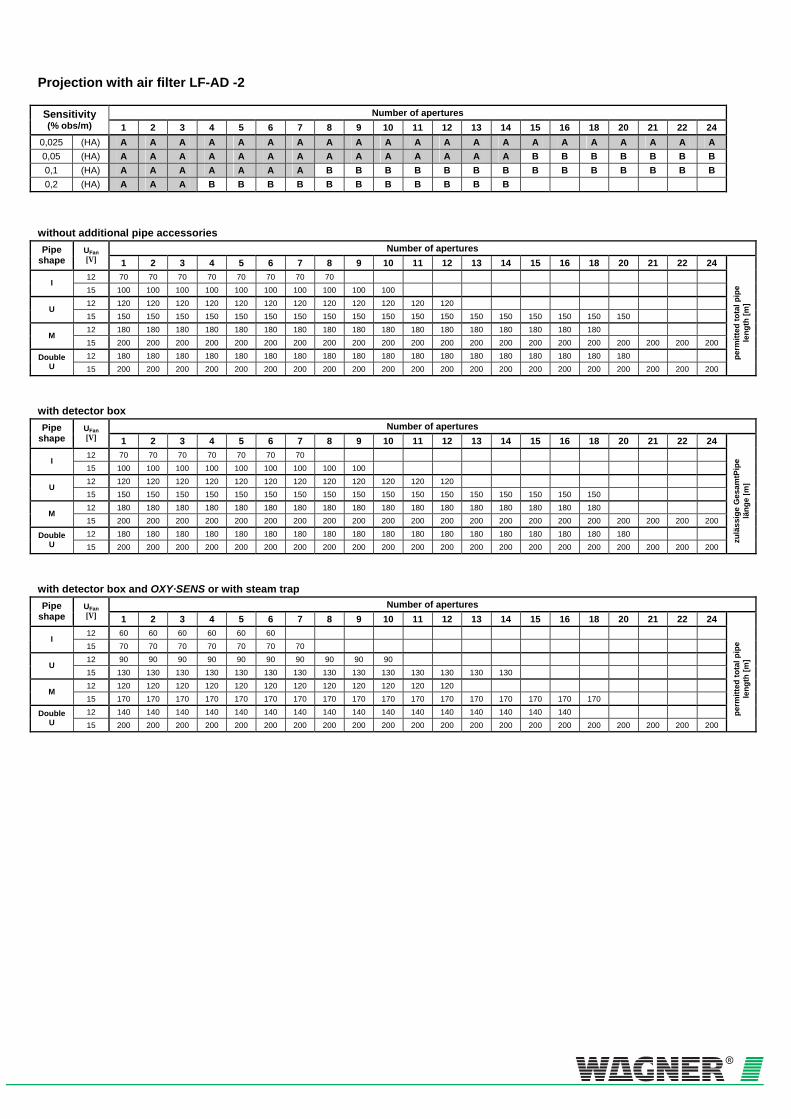
Projection with air filter LF-AD -2
Number of apertures Sensitivity (% obs/m) 1 2 3 4 5 6 7 8 9 10 11 12 13 14 15 16 18 20 21 22 24
0,025 (HA) A A A A A A A A A A A A A A A A A A A A A 0,05 (HA) A A A A A A A A A A A A A A B B B B B B B 0,1 (HA) A A A A A A A B B B B B B B B B B B B B B 0,2 (HA) A A A B B B B B B B B B B B
without additional pipe accessories
Number of apertures Pipe shape
UFan [V] 1 2 3 4 5 6 7 8 9 10 11 12 13 14 15 16 18 20 21 22 24 12 70 70 70 70 70 70 70 70
I 15 100 100 100 100 100 100 100 100 100 100 12 120 120 120 120 120 120 120 120 120 120 120 120
U 15 150 150 150 150 150 150 150 150 150 150 150 150 150 150 150 150 150 150 12 180 180 180 180 180 180 180 180 180 180 180 180 180 180 180 180 180
M 15 200 200 200 200 200 200 200 200 200 200 200 200 200 200 200 200 200 200 200 200 200 12 180 180 180 180 180 180 180 180 180 180 180 180 180 180 180 180 180 180 Double
U 15 200 200 200 200 200 200 200 200 200 200 200 200 200 200 200 200 200 200 200 200 200
perm
itted
tota
l pip
e le
ngth
[m]
with detector box
Number of apertures Pipe shape
UFan [V] 1 2 3 4 5 6 7 8 9 10 11 12 13 14 15 16 18 20 21 22 24 12 70 70 70 70 70 70 70
I 15 100 100 100 100 100 100 100 100 100 12 120 120 120 120 120 120 120 120 120 120 120 120
U 15 150 150 150 150 150 150 150 150 150 150 150 150 150 150 150 150 150 12 180 180 180 180 180 180 180 180 180 180 180 180 180 180 180 180 180
M 15 200 200 200 200 200 200 200 200 200 200 200 200 200 200 200 200 200 200 200 200 200 12 180 180 180 180 180 180 180 180 180 180 180 180 180 180 180 180 180 180 Double
U 15 200 200 200 200 200 200 200 200 200 200 200 200 200 200 200 200 200 200 200 200 200
zulä
ssig
e G
esam
tPip
e lä
nge [m
]
with detector box and OXY·SENS or with steam trap
Number of apertures Pipe shape
UFan [V] 1 2 3 4 5 6 7 8 9 10 11 12 13 14 15 16 18 20 21 22 24 12 60 60 60 60 60 60
I 15 70 70 70 70 70 70 70 12 90 90 90 90 90 90 90 90 90 90
U 15 130 130 130 130 130 130 130 130 130 130 130 130 130 130 12 120 120 120 120 120 120 120 120 120 120 120 120
M 15 170 170 170 170 170 170 170 170 170 170 170 170 170 170 170 170 170 12 140 140 140 140 140 140 140 140 140 140 140 140 140 140 140 140 Double
U 15 200 200 200 200 200 200 200 200 200 200 200 200 200 200 200 200 200 200 200 200 200 pe
rmitt
ed to
tal p
ipe
leng
th [m
]

Projection with air filter SF X00
Number of apertures Sensitivity (% obs/m) 1 2 3 4 5 6 7 8 9 10 11 12 13 14 15 16 18 20 21 22 24
0,025 (HA) A A A A A A A A A B B B B B B B B B B B B 0,05 (HA) A A A A B B B B B B B B B B B B B 0,1 (HA) A A B B B B B B B 0,2 (HA) A B B B
without additional pipe accessories
Number of apertures Pipe shape
UFan [V] 1 2 3 4 5 6 7 8 9 10 11 12 13 14 15 16 18 20 21 22 24 12 70 70 70 70 70 70 70
I 15 100 100 100 100 100 100 100 100 100 12 120 120 120 120 120 120 120 120 120 120 120 120
U 15 150 150 150 150 150 150 150 150 150 150 150 150 150 150 150 150 150 12 180 180 180 180 180 180 180 180 180 180 180 180 180 180 180 180 180
M 15 200 200 200 200 200 200 200 200 200 200 200 200 200 200 200 200 200 200 200 200 200 12 180 180 180 180 180 180 180 180 180 180 180 180 180 180 180 180 180 180 Double
U 15 200 200 200 200 200 200 200 200 200 200 200 200 200 200 200 200 200 200 200 200 200
perm
itted
tota
l pip
e le
ngth
[m]
with detector box and OXY·SENS or with steam trap
Number of apertures Pipe shape
UFan [V] 1 2 3 4 5 6 7 8 9 10 11 12 13 14 15 16 18 20 21 22 24 12 60 60 60 60 60 60
I 15 70 70 70 70 70 70 70 12 90 90 90 90 90 90 90 90 90 90
U 15 130 130 130 130 130 130 130 130 130 130 130 130 130 130 12 120 120 120 120 120 120 120 120 120 120 120 120
M 15 170 170 170 170 170 170 170 170 170 170 170 170 170 170 170 170 170 12 140 140 140 140 140 140 140 140 140 140 140 140 140 140 140 140 Double
U 15 200 200 200 200 200 200 200 200 200 200 200 200 200 200 200 200 200 200 200 200 200
perm
itted
tota
l pip
e le
ngth
[m]


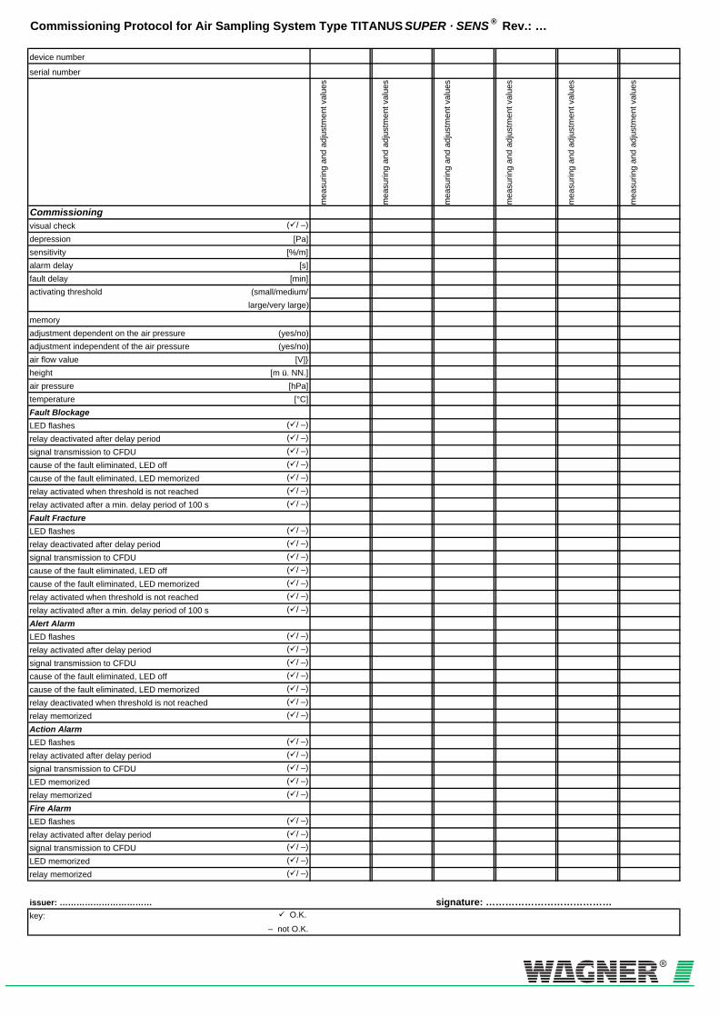
Commissioning Protocol for Air Sampling System Type TITANUS SUPER · SENS ® Rev.: …
device number
serial number
mea
surin
g an
d ad
just
men
t val
ues
mea
surin
g an
d ad
just
men
t val
ues
mea
surin
g an
d ad
just
men
t val
ues
mea
surin
g an
d ad
just
men
t val
ues
mea
surin
g an
d ad
just
men
t val
ues
mea
surin
g an
d ad
just
men
t val
ues
Commissioningvisual check ( / –)
depression [Pa]sensitivity [%/m]alarm delay [s]fault delay [min]activating threshold (small/medium/
large/very large)
memoryadjustment dependent on the air pressure (yes/no)adjustment independent of the air pressure (yes/no)air flow value [V]}height [m ü. NN.]air pressure [hPa]temperature [°C]Fault BlockageLED flashes ( / –)
relay deactivated after delay period ( / –)
signal transmission to CFDU ( / –)
cause of the fault eliminated, LED off ( / –)
cause of the fault eliminated, LED memorized ( / –)
relay activated when threshold is not reached ( / –)
relay activated after a min. delay period of 100 s ( / –)
Fault FractureLED flashes ( / –)
relay deactivated after delay period ( / –)
signal transmission to CFDU ( / –)
cause of the fault eliminated, LED off ( / –)
cause of the fault eliminated, LED memorized ( / –)
relay activated when threshold is not reached ( / –)
relay activated after a min. delay period of 100 s ( / –)
Alert AlarmLED flashes ( / –)
relay activated after delay period ( / –)
signal transmission to CFDU ( / –)
cause of the fault eliminated, LED off ( / –)
cause of the fault eliminated, LED memorized ( / –)
relay deactivated when threshold is not reached ( / –)
relay memorized ( / –)
Action AlarmLED flashes ( / –)
relay activated after delay period ( / –)
signal transmission to CFDU ( / –)
LED memorized ( / –)
relay memorized ( / –)
Fire AlarmLED flashes ( / –)
relay activated after delay period ( / –)
signal transmission to CFDU ( / –)
LED memorized ( / –)
relay memorized ( / –)
issuer: …………………………… signature: …………………………………key: O.K.
– not O.K.


TITANUS SUPER · SENS® Glossary
TSS-GLOSSARY_en – Data: 02/09
Glossary
Technical Term Definition
A action alarm At this alarm level first measures are taken as e.g.
the cutoff of a device (→fire alarm, →alert alarm).
aerosol also: smoke aerosol
An aerosol is a floating particle in the microscopic or submicroscopic particle size range. They consist of unburned parts of the fire load, intermediate products of the oxidation and finely divided carbon (soot).
air sampling smoke detection system Active system of which the underpressure to take air samples is produced by a ventilator fan belonging to the system. The air samples are then passed to a detection unit (smoke detector or detector head).
alarm Acoustic and/or optical signal activated through →smoke detectors to indicate a fire.
alarm current An increased current in the →alarm state (→quiescent current).
alarm state The state of a fire detection installation or a part of it as reaction on an exisiting danger.
alert alarm Defined or, depending on the device, variable alarm threshold according to the smoke level. The alert alarm informs about a deviation from the nomal state and allows to take further measures (→fire alarm, →action alarm).
automatic smoke detector Automatic detectors are detectors which detect and analyze physical parameters which serve to create danger warning signals. Automatic smoke detectors are e.g. point-type detectors, →multi-point detectors, →linear detectors, →flame detectors and →air sampling smoke detection systems.
C CMOS Complementary Metal Oxide Semiconductor,
complementary MOS-technoloy
collective alarm A non-differentiated, i.g. non-localizable →alarm, which is indicated at a superior system.
collective detection system Conventional detection line technology; the detectors connected to the same detection line form a collective address (common display and operation without identification of the single detectors)

TITANUS SUPER · SENS® Glossary
TSS-GLOSSARY_en – Data: 02/09
C
central fire panel Central part of a fire detection installation which supplies the detectors with power, receives signals to display them optically and acoustically and, if required, transmits them and which checks the installation for faults.
collective detector Smoke detectors with conventional limiting value-detector technology. They are suitable for areas with low risks of fire and unproblematic ambient conditions.
collective fault A non-differentiated, i.g. non-localizable →fault signal which is indicated at a superior system.
control in case of a fire Equipment or fire prevention installation automatically or manually triggered by the →central fire panel to reduce the danger to human life and minimize damage caused by fire.
D detection line Monitored transmission line (→primary line)
through which the smoke detectors are connected with the →central fire panel.
display sensitivity The display sensitivity describes the sensitivity level at which the air sampling system starts detecting smoke particles (level 1). It is displayed by means of a bargraph. (→response sensitivity →detector head sensitivity)
detection reliability The detection reliability is the quantity of reliability with which phenomena are detected and indicated for whose perception a detection system is used.
detector group Collection of smoke detectors in a →detection line, for which an own display in the →central fire panel is installed.
detector head sensitivity The detector head sensitivity is a sensitivity adjustable between level 1 and 4 and is the general term of →response sensitivity and →display sensitivity.
differential heat detector The increase in heat per unit of time is evaluated for the alarm activation.
DIL-switch dual in line; e.g. to set the air flow sensor technology, the response sensitivity, the delay period for →alarm and fault and to set the alarm to “latched“ or “non-latched“.

TITANUS SUPER · SENS® Glossary
TSS-GLOSSARY_en – Data: 02/09
E
electromagnetic compatibility (EMC) The electromagnetic compatibility is the ability of an electrical or electronical system to operate correctly in its electromagnetic environment and to have no unallowed impact on this environment.
end of line resistor Element at the end of a →detection or control line to check the line for broken wires and short circuits
extinction smoke detector Extinction smoke detectors react to products of combustion which cause the subdueing and scattering of light.
F fault signal Signal indicating a deviation from the desired
value in the →smoke detection installation.
fire alarm Defined or, depending on the device, variable alarm threshold according to the smoke level. Fire alarm means the detection of a fire, the fire department is informed (→alert alarm, →action alarm).
fire load The fire load corresponds to the quantity of heat of all combustible materials of a fire section referred to its area.
fire section Isolated section in a building which avoids or slows down the spreading of a fire to a neighboring section through special constructions.
fire-resistant collar Constructions that avoid a flame/smoke spread in cable ducts as well as in chases and break-throughs for wiring through walls and ceilings.
flame detector The flame detector transfers the electromagnetic radiation produced by the flames into an electrical signal which is analyzed for the alarm activation.
H head control The head control is an electronic board in the
detector head and contains the control electronics for the detector head. It provides the smoke signal for further processing.
I interactive detector Detector series with highest detection reliability of
the evaluation and decision logics with interactive signal processing based on programmable algorithms. The detectors are parameterizable; they can be programmed through a software in an optimum way for the conditions of the mounting location.
interference Interferences in smoke detection installations are the totality of external parameters which have an impact on the intended function of a smoke detection installation.
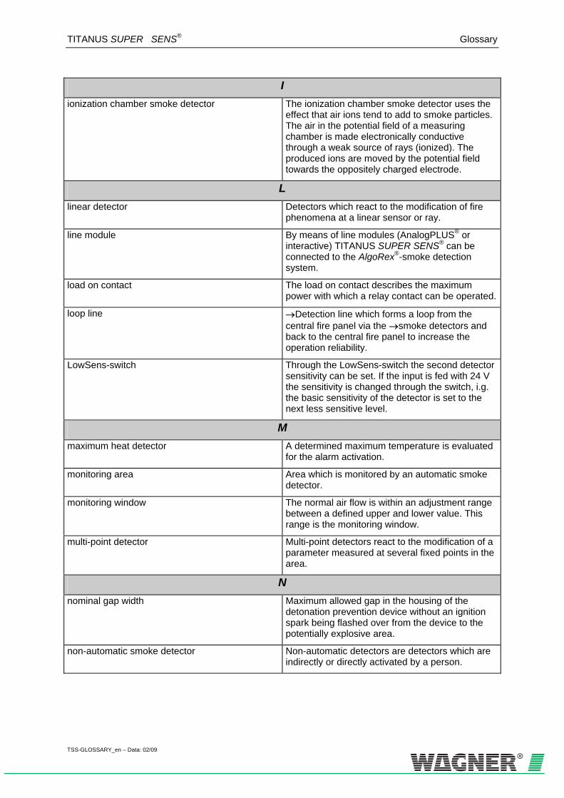
TITANUS SUPER · SENS® Glossary
TSS-GLOSSARY_en – Data: 02/09
I
ionization chamber smoke detector The ionization chamber smoke detector uses the effect that air ions tend to add to smoke particles. The air in the potential field of a measuring chamber is made electronically conductive through a weak source of rays (ionized). The produced ions are moved by the potential field towards the oppositely charged electrode.
L linear detector Detectors which react to the modification of fire
phenomena at a linear sensor or ray.
line module By means of line modules (AnalogPLUS® or interactive) TITANUS SUPER·SENS® can be connected to the AlgoRex®-smoke detection system.
load on contact The load on contact describes the maximum power with which a relay contact can be operated.
loop line →Detection line which forms a loop from the central fire panel via the →smoke detectors and back to the central fire panel to increase the operation reliability.
LowSens-switch Through the LowSens-switch the second detector sensitivity can be set. If the input is fed with 24 V the sensitivity is changed through the switch, i.g. the basic sensitivity of the detector is set to the next less sensitive level.
M maximum heat detector A determined maximum temperature is evaluated
for the alarm activation.
monitoring area Area which is monitored by an automatic smoke detector.
monitoring window The normal air flow is within an adjustment range between a defined upper and lower value. This range is the monitoring window.
multi-point detector Multi-point detectors react to the modification of a parameter measured at several fixed points in the area.
N nominal gap width Maximum allowed gap in the housing of the
detonation prevention device without an ignition spark being flashed over from the device to the potentially explosive area.
non-automatic smoke detector Non-automatic detectors are detectors which are indirectly or directly activated by a person.

TITANUS SUPER · SENS® Glossary
TSS-GLOSSARY_en – Data: 02/09
P
parameterization Through the paremeterization the character of the algorithm and therefore its effect are determined. Through the choice of the appropriate algorithm (parameterization) the detector is specifically adapted to the fire phenomena and ambient conditions to be expected. This application-specific parameterization permits a significantly increased alarm reliability.
primary line Primary lines are transmission lines permanently and automatically checked for short circuit and interruption. They serve for the transmission of signals of important functions of →smoke detection installations.
Q quiescent current Current on the →detection line in its normal
operational state, →alarm current
R repeater A repeater can bridge a distance of up to 2000 m
between the →air sampling smoke detection system and the remote display unit. It is installed after a max. distance of 1000 m and amplifies the signal to be transmitted.
response sensitivity The response sensitivity is the sensitivity at which a fire alarm is activated (lighting of all LEDs) (→display sensitivity, →detector head sensitivity).
S scattered light smoke detector Scattered light smoke detectors react to products
of combustion which scatter the light.
secondary line Non-monitored transmission lines.
sensitivity The set sensitivity of an air sampling system determines at which light obscuration per meter an alert, action or fire alarm is activated. Each device has four adjustable sensitivity levels. (→detector head sensitivity, →display sensitivity, →response sensitivity)
single-hole monitoring Detection of changes (e.g. blockages) of the diameter of each single air sampling point.
smoke aerosol aerosol
smoke detection installation Smoke detection installations are danger detection systems which serve persons to directly call for help in case of a fire and/or to detect and indicate the fire early.

TITANUS SUPER · SENS® Glossary
TSS-GLOSSARY_en – Data: 02/09
S
smoke detector Smoke detectors react to the combustible particles and/or →aerosols (floating particles) in the air. One distinguishes → ionization chamber smoke detectors and optical smoke detectors (→extinction smoke detectors and →scattered light smoke detectors).
smoldering fire Smoldering fires develop from a seat of fire; later on they become open fires after a considerable smoke development.
T temperature compensation The air flow in the pipe is not falsified by
temperature variations.
two-detector dependency System to verify alarm states. The fire alarm is activated after two detectors of a →detector group have been actuated. When the first detector has been actuated an internal alarm or a control function can be activated.
two-group dependency System to verify alarm states. The fire alarm is activated after one detector each of two related →detector groups has been actuated. When the first detector has been actuated an internal alarm or a control function can be activated.
V value concentration The value concentration is an important factor for
the evaluation of the risk of fire. It is determined by the values to be protected. It is also to be considered if the values exposed to the risk of fire are recoverable which will be nearly impossible for cultural assets.
W watchdog Monitoring circuit which is activated when the
microprocessor fails.
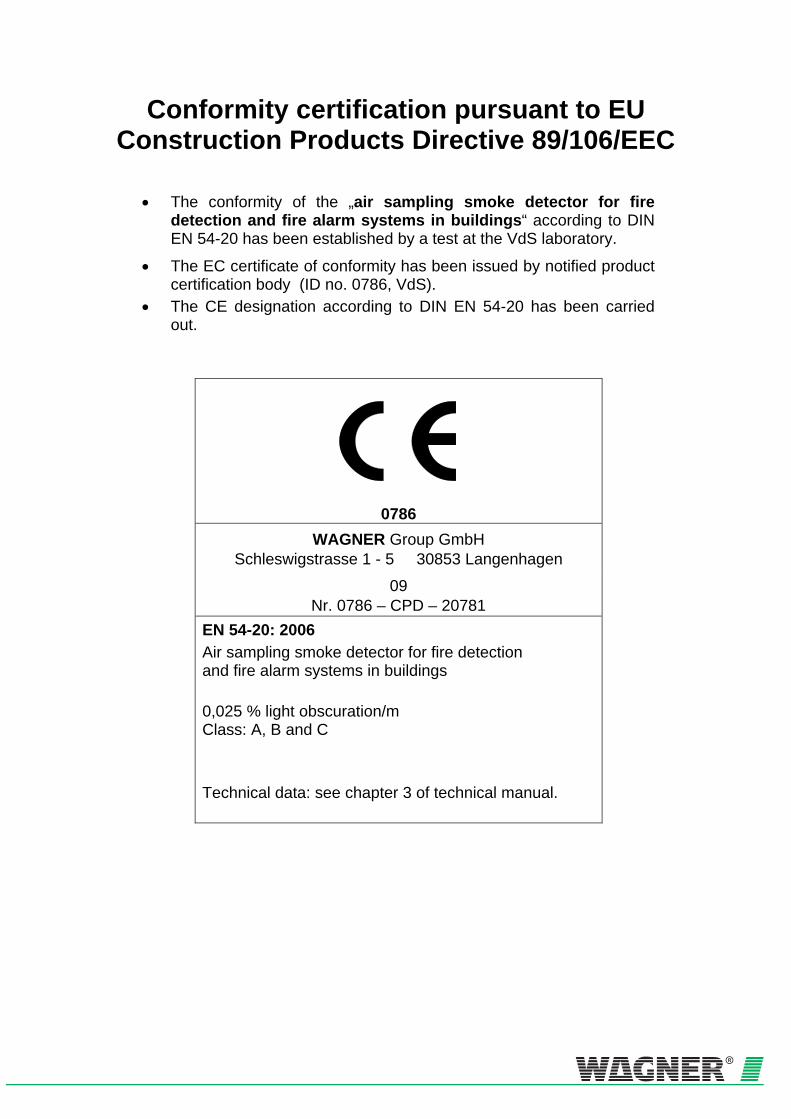
Conformity certification pursuant to EU Construction Products Directive 89/106/EEC
• The conformity of the „air sampling smoke detector for fire detection and fire alarm systems in buildings“ according to DIN EN 54-20 has been established by a test at the VdS laboratory.
• The EC certificate of conformity has been issued by notified product certification body (ID no. 0786, VdS).
• The CE designation according to DIN EN 54-20 has been carried out.
0786
WAGNER Group GmbH Schleswigstrasse 1 - 5 30853 Langenhagen
09 Nr. 0786 – CPD – 20781
EN 54-20: 2006 Air sampling smoke detector for fire detection and fire alarm systems in buildings 0,025 % light obscuration/m Class: A, B and C Technical data: see chapter 3 of technical manual.


WAGNER Group GmbH
Hauptsitz Schleswigstraße 1 - 5
D-30853 Langenhagen +49 (0) 511 - 973 83-0
+49 (0) 5 11- 97383-260 [email protected]
Deutschland: WAGNER Group GmbH Niederlassung Berlin Am Müggelpark 19 D-15537 Gosen-Neu Zittau
+49 (0)3362 - 7406 - 0 +49 (0)3362 - 7406 -19
WAGNER Group GmbH Niederlassung Mülheim/Ruhr Reichstraße 37-39 D-45479 Mülheim a.d. Ruhr
+49 (0)208 - 41995-0 +49 (0)208 - 41995-13
WAGNER Bayern GmbH Trausnitzstraße 8 D-81671 München
+49 (0)89 - 450551-0 +49 (0)89 - 450551-99
WAGNER Group GmbH Niederlassung Berlin - Büro Leipzig Zeppelinstraße 2 D-04509 Wiedemar
+49 (0)34207 - 645-0 +49 (0)34207 - 645-19
Wagner Group GmbH Niederlassung Mülheim/Ruhr - Vertriebsbüro Köln Lukasstraße 30 D-50823 Köln
+49 (0)0221 - 9524203 +49 (0)0221 - 9524217
Wagner Bayern GmbH Vertriebsbüro Illertissen Dietenheimer Str. 19 b D-89257 Illertissen
+49 (0)07303 - 95191 -12 +49 (0)07303 - 95191 -99
WAGNER Group GmbH Niederlassung Hamburg Stuvenborner Straße 8A D-24643 Struvenhütten
+49 (0)4194 - 9970-0 +49 (0)4194 - 9970-99
WAGNER Group GmbH Niederlassung Frankfurt Siemensstraße 1 D-61239 Ober-Mörlen
+49 (0)6002 - 9106-0 +49 (0)6002 - 9106-19
WAGNER Group GmbH Niederlassung Hannover Schleswigstraße 3 D-30853 Langenhagen
+49 (0)511 - 97383-0 +49 (0)511- 97383-140
WAGNER Group GmbH Niederlassung Stuttgart Schwieberdingerstraße 60/1 D-71636 Ludwigsburg
+49 (0)7141 - 488798-0 +49 (0)7141- 488798-19
Europa: WAGNER Austria GmbH Am Hafen 6 A-2100 Korneuburg
+43 (0)2262 - 64262 -0 +43 (0)2262 - 64262-19
WAGNER Nederland B.V. Manitobadreef 11, 3565 CH Utrecht Postbus 9752 NL-3506 GT Utrecht
+31 (0)30 - 2200264 +31 (0)30 - 2201917
WAGNER UK Limited Wagner House - Unit F South Cambridge Business Park Babraham Road Sawston Cambridge CB22 3JH
+44 (0)870 - 3336116 +44 (0)870 - 3334544
WAGNER SCHWEIZ AG Industriestrasse 44 CH-8304 Wallisellen
+41 (0)44 - 8325400 +41 (0)44 - 8325409
WAGNER Poland Sp. z o.o. i Sp. k. ul. Puławska 38 PL 05-500 Piaseczno
+48 (0)22 - 7263550 +48 (0)22 - 7263551
Middle East: WAGNER Middle East FZE Dubai Airport FreeZone Authority P.O. Box 54651 Building E2, Room 105 Dubai U.A.E
+ 971 (0) 4299 0887 + 971 (0) 4299 1799
