air preparation description page units ... - ara pneumatik · 21 overview description page...
TRANSCRIPT

21
Overview
Description Page
Characteristics Dimensions Order instructions Type overview
Air preparation unit three-piece 22, 23, 26 29 37, 39
Air preparation unit two-piece 22, 23, 26 29 37, 39
Filter-regulator 22, 23, 26 30 37, 39
Filter-water-separator 22, 23, 26 30 37, 39
Dust filter 22, 23, 26 30 37, 39
Pressure regulating valve 22, 23, 27 31, 32 38, 39
Pressure regulating valve, pilot operated
22, 23, 27 33 38, 39
Oil mist lubricator 24, 25, 28 33 38, 39
Start valve 24, 25 34 38, 39
Stop valve 24, 25 34, 35 38, 39
Submicrofilter 24, 25 35 39
Activated carbon filter 24, 25 35 39
3/2 Way shut-off valve 24, 25 36 39
Accessories 40, 41 39–41 39–41
Air preparation units
Series airfit swing G1/4, G3/8
pneumatic
www.arapneumatik.pl
ARA Pneumatik Wrocùaw 53-012 Wrocùaw ul. Wy �cig owa 38 tel. 71 364 72 80; 82 fax 71 364 72 83 [email protected]
ARA Pneumatik Oddziaù Katowice 40-584 Katowice ul. Dworska 13 tel. 32 779 76 40; 41 fax 32 778 20 93 [email protected]

22
Air preparation units
Series airfit swing G1/4, G3/8
Characteristics
Special solutions (e.g. temperature, pressure, medium ...) on request, or see page 167–178 for special units
Pressures quoted as gauge pressureCharacteristics Symbol Unit Air preparation
unit three-pieceAir preparation unit two-piece
Filter-regulator Filter-water-separator Dust filter Pressure regulating valve
Pressure regulating valve pilot operated
System Consisting of filter-water-separator, pressure regulating valve, oil mist lubricator*, gauge, mounting bracket
Consisting of filter-regulator, oil mist lubricator*, gauge, mounting bracket
Cyclone system with filter element combined with diaphragm-type pressure regulating valve (spring loaded) with secondary pres-sure relief, handwheel lockable
With cyclone system and filter element
With cyclone system and dust filter element
Diaphragm-type pres-sure regulating valve (spring loaded) with secondary pressure re-lief, inlet pressure and volume compensation, locating ring, hand-wheel lockable
Pilot operated piston-type pressure regulator with secondary pressure relief and flow compensation 4)
Type SFRL-1/4 SFRL-3/8 SKL-1/4 SKL-3/8 SK-1/4 SK-3/8 SF-1/4 SF-3/8 SFD-1/4 SFD-3/8 SR-1/4 (-T)
SR-3/8 (-T)
SRV-1/4
Material– Housing Diecast zinc Diecast zinc– Plastic bowl Polycarbonate Polycarbonate Polycarbonate Polycarbonate Polycarbonate – –– Metal bowl Diecast zinc Diecast zinc Diecast zinc Diecast zinc Diecast zinc – –– Diaphragm NBR NBR NBR NBR NBR– Standard sealings NBR NBRPort size (NPTF version)
G1/4 G3/8 G1/4 G3/8 G1/4 G3/8 G1/4 G3/8 G1/4 G3/8 G1/4 G3/8 G1/4
Max. condensate capacity
cm3 22 22 22 22 22 22 22 22 22 22 – –
Pore size of filter element
µm 30 or 5 30 or 5 30 or 5 30 or 5 1
Condensate drainage Manual, semi-automatic (pressure relief), or automatic (float type)
Manual, semi-automatic (pressure relief), or automatic (float type)
Manual – –
Oil/air ratio Constant oil drip rate independent of air flow
Max. oil capacity cm3 45 45 – – – – –Oil refilling Manual – also during operation – – – _ _
Installation Vertical, bowl at the bottom
Vertical, bowl at the bot-tom
Vertical, bowl at the bottom
Vertical, bowl at the bottom
Vertical, bowl at the bottom
In any position In any position
Medium and ambient temperatures
TminTmax
°C°C
0 +50 at 10 bar (further temperatures on request)
0 +50 at 10 bar (further temperatures on request)
0 +50 at 10 bar(further temperatures on request)
0 +50 at 10 bar(further temperatures on request)
0 +50 at 10 bar(further temperatures on request)
0 +60 at 10 bar(further temperatures on request)
0 +60 at 10 bar(further temperatures on request)
Weight (mass) kg 0.95 0.75 0.35 0.25 0.25 0.30 0.40Pneumatic characteristicsOperating pressure range – inlet pressure
p1 minp1 max
bar bar
0 16
0 16
0 16
0 16
0 16
0 16
0 16
Operating pressure range – outlet pressure
p2 min/max bar 0.5 to 8 on request 0.5 to 43) on request 0.5 to 153)
0.5 to 8 on request 0.5 to 43) on request 0.5 to 153)
0.5 to 8 On request 0.5 to 43) On request 0.5 to 153)
0.5 to 8 On request 0.5 to 43) On request 0.5 to 153)
–
Min. pressure difference p1–p2 0.2 0.2 0.2Hysteresis p1=10/p2=0
p1=10/p2=80.50.4
0.50.4
0.50.4
Maximum flow 1) Qmax l/min m3/h
825 50
790 47
890 53
790 47
2280 137
3200 192
1440 86
1520 91
1340 80
1620 97
2850 171
3300 198
2200 132
Degree of moisture separation at recommended flow
h % > 95 > 90 > 95 > 90 > 95 > 90 > 95 > 90 Only solid particles > 99% related to 1 µm
– –
1) at p1 =10 bar and p2 = 6.3 bar, Dp = 1 bar2) at 6 bar and 25 m/s flow velocity3) By the use of special springs, the outlet pressure can be precisely regulated
in the specified p2 range4) Recommended pilot pressure regulating valve MRP-1/8 (see page 9)*) Use only recommended oils with viscosity VG32 to ISO 3448 (32 mm2/s at 40°C)
or Parker Origa compressed air oil, Order No.: KG6140 (see page 203)

23
For more characteristics of air preparation units see page 24–25
Pressures quoted as gauge pressureCharacteristics Symbol Unit Air preparation
unit three-pieceAir preparation unit two-piece
Filter-regulator Filter-water-separator Dust filter Pressure regulating valve
Pressure regulating valve pilot operated
System Consisting of filter-water-separator, pressure regulating valve, oil mist lubricator*, gauge, mounting bracket
Consisting of filter-regulator, oil mist lubricator*, gauge, mounting bracket
Cyclone system with filter element combined with diaphragm-type pressure regulating valve (spring loaded) with secondary pres-sure relief, handwheel lockable
With cyclone system and filter element
With cyclone system and dust filter element
Diaphragm-type pres-sure regulating valve (spring loaded) with secondary pressure re-lief, inlet pressure and volume compensation, locating ring, hand-wheel lockable
Pilot operated piston-type pressure regulator with secondary pressure relief and flow compensation 4)
Type SFRL-1/4 SFRL-3/8 SKL-1/4 SKL-3/8 SK-1/4 SK-3/8 SF-1/4 SF-3/8 SFD-1/4 SFD-3/8 SR-1/4 (-T)
SR-3/8 (-T)
SRV-1/4
Material– Housing Diecast zinc Diecast zinc– Plastic bowl Polycarbonate Polycarbonate Polycarbonate Polycarbonate Polycarbonate – –– Metal bowl Diecast zinc Diecast zinc Diecast zinc Diecast zinc Diecast zinc – –– Diaphragm NBR NBR NBR NBR NBR– Standard sealings NBR NBRPort size (NPTF version)
G1/4 G3/8 G1/4 G3/8 G1/4 G3/8 G1/4 G3/8 G1/4 G3/8 G1/4 G3/8 G1/4
Max. condensate capacity
cm3 22 22 22 22 22 22 22 22 22 22 – –
Pore size of filter element
µm 30 or 5 30 or 5 30 or 5 30 or 5 1
Condensate drainage Manual, semi-automatic (pressure relief), or automatic (float type)
Manual, semi-automatic (pressure relief), or automatic (float type)
Manual – –
Oil/air ratio Constant oil drip rate independent of air flow
Max. oil capacity cm3 45 45 – – – – –Oil refilling Manual – also during operation – – – _ _
Installation Vertical, bowl at the bottom
Vertical, bowl at the bot-tom
Vertical, bowl at the bottom
Vertical, bowl at the bottom
Vertical, bowl at the bottom
In any position In any position
Medium and ambient temperatures
TminTmax
°C°C
0 +50 at 10 bar (further temperatures on request)
0 +50 at 10 bar (further temperatures on request)
0 +50 at 10 bar(further temperatures on request)
0 +50 at 10 bar(further temperatures on request)
0 +50 at 10 bar(further temperatures on request)
0 +60 at 10 bar(further temperatures on request)
0 +60 at 10 bar(further temperatures on request)
Weight (mass) kg 0.95 0.75 0.35 0.25 0.25 0.30 0.40Pneumatic characteristicsOperating pressure range – inlet pressure
p1 minp1 max
bar bar
0 16
0 16
0 16
0 16
0 16
0 16
0 16
Operating pressure range – outlet pressure
p2 min/max bar 0.5 to 8 on request 0.5 to 43) on request 0.5 to 153)
0.5 to 8 on request 0.5 to 43) on request 0.5 to 153)
0.5 to 8 On request 0.5 to 43) On request 0.5 to 153)
0.5 to 8 On request 0.5 to 43) On request 0.5 to 153)
–
Min. pressure difference p1–p2 0.2 0.2 0.2Hysteresis p1=10/p2=0
p1=10/p2=80.50.4
0.50.4
0.50.4
Maximum flow 1) Qmax l/min m3/h
825 50
790 47
890 53
790 47
2280 137
3200 192
1440 86
1520 91
1340 80
1620 97
2850 171
3300 198
2200 132
Degree of moisture separation at recommended flow
h % > 95 > 90 > 95 > 90 > 95 > 90 > 95 > 90 Only solid particles > 99% related to 1 µm
– –
1) at p1 =10 bar and p2 = 6.3 bar, Dp = 1 bar2) at 6 bar and 25 m/s flow velocity3) By the use of special springs, the outlet pressure can be precisely regulated
in the specified p2 range4) Recommended pilot pressure regulating valve MRP-1/8 (see page 9)*) Use only recommended oils with viscosity VG32 to ISO 3448 (32 mm2/s at 40°C)
or Parker Origa compressed air oil, Order No.: KG6140 (see page 203)
24
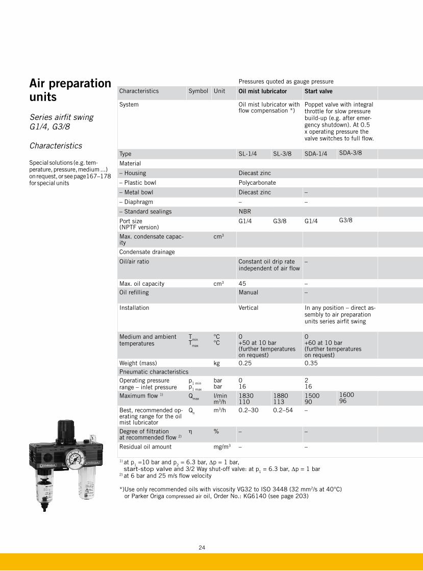
Pressures quoted as gauge pressure
Characteristics Symbol Unit Oil mist lubricator Start valve Stop valve Submicrofilter Activated carbon filter 3/2 Way shut-off valve
System Oil mist lubricator with flow compensation *)
Poppet valve with integral throttle for slow pressure build-up (e.g. after emer-gency shutdown). At 0.5 x operating pressure the valve switches to full flow.
3/2 Way poppet valve with pneumatic (P) or electrical (E) actuation and integrated exhaust silencer
3/2 Way valve (spool type), direct assembly to any unit from the airfit swing series, with coupling kit PL16959
Type SL-1/4 SL-3/8 SDA-1/4 SDA-3/8 SDR-1/4P (E) SDR-3/8P (E) MF012-1/4 MF012-3/8 MC012-1/4 MC012-3/8 SDV-1/4-XS SDV-3/8-XS
Material
– Housing Diecast zinc Diecast zinc
– Plastic bowl Polycarbonate – Polycarbonate Polycarbonate
– Metal bowl Diecast zinc – – Diecast zinc Diecast zinc – –
– Diaphragm – – – – – –
– Standard sealings NBR NBR
Port size (NPTF version)
G1/4 G3/8 G1/4 G3/8 G1/4 G3/8 G1/4 G3/8 G1/4 G3/8 G1/4 G3/8
Max. condensate capac-ity
cm3 13 13 – – – –
Condensate drainage Manual Manual
Oil/air ratio Constant oil drip rate independent of air flow
– – – – – –
Max. oil capacity cm3 45 – – – – – –
Oil refilling Manual – – – – – –
Installation Vertical In any position – direct as-sembly to air preparation units series airfit swing
Follow the installation notes Vertical, bowl at the bottom Vertical, bowl at the bottom In any position
Medium and ambient temperatures
TminTmax
°C °C
0 +50 at 10 bar (further temperatures on request)
0 +60 at 10 bar (further temperatures on request)
0 +60 at 10 bar(further temperatures on request)
0 +50 at 10 bar
0 +40 at 10 bar
0 +60 at 10 bar (further temperatures on request)
Weight (mass) kg 0.25 0.35 0.5 (P) 0.8 (E) 0.30 0.30 0.25
Pneumatic characteristicsOperating pressure range – inlet pressure
p1 minp1 max
bar bar
0 16
2 16
2 16 (10 E)
0 16
0 16
0 16
Maximum flow 1) Qmax l/min m3/h
1830 110
1880 113
1500 90
1600 96
1500 90
1600 96
580 at 6 bar 35
580 at 6 bar 35
4100 246
5300 318
Best, recommended op-erating range for the oil mist lubricator
Qn m3/h 0.2–30 0.2–54 – – – – –
Degree of filtration at recommended flow 2)
h % – – – Over 99.99999% related to 0.01µm
_ –
Residual oil amount mg/m3 – – – < 0.01 input conc. 3 mg/m3 0.003 ‰ in combination MF –
1) at p1 =10 bar and p2 = 6.3 bar, Dp = 1 bar, start-stop valve and 3/2 Way shut-off valve: at p1 = 6.3 bar, Dp = 1 bar
2) at 6 bar and 25 m/s flow velocity
*) Use only recommended oils with viscosity VG32 to ISO 3448 (32 mm2/s at 40°C) or Parker Origa compressed air oil, Order No.: KG6140 (see page 203)
Air preparation units
Series airfit swing G1/4, G3/8
Characteristics
Special solutions (e.g. tem-perature, pressure, medium ...) on request, or see page167–178 for special units

25
Pressures quoted as gauge pressure
Characteristics Symbol Unit Oil mist lubricator Start valve Stop valve Submicrofilter Activated carbon filter 3/2 Way shut-off valve
System Oil mist lubricator with flow compensation *)
Poppet valve with integral throttle for slow pressure build-up (e.g. after emer-gency shutdown). At 0.5 x operating pressure the valve switches to full flow.
3/2 Way poppet valve with pneumatic (P) or electrical (E) actuation and integrated exhaust silencer
3/2 Way valve (spool type), direct assembly to any unit from the airfit swing series, with coupling kit PL16959
Type SL-1/4 SL-3/8 SDA-1/4 SDA-3/8 SDR-1/4P (E) SDR-3/8P (E) MF012-1/4 MF012-3/8 MC012-1/4 MC012-3/8 SDV-1/4-XS SDV-3/8-XS
Material
– Housing Diecast zinc Diecast zinc
– Plastic bowl Polycarbonate – Polycarbonate Polycarbonate
– Metal bowl Diecast zinc – – Diecast zinc Diecast zinc – –
– Diaphragm – – – – – –
– Standard sealings NBR NBR
Port size (NPTF version)
G1/4 G3/8 G1/4 G3/8 G1/4 G3/8 G1/4 G3/8 G1/4 G3/8 G1/4 G3/8
Max. condensate capac-ity
cm3 13 13 – – – –
Condensate drainage Manual Manual
Oil/air ratio Constant oil drip rate independent of air flow
– – – – – –
Max. oil capacity cm3 45 – – – – – –
Oil refilling Manual – – – – – –
Installation Vertical In any position – direct as-sembly to air preparation units series airfit swing
Follow the installation notes Vertical, bowl at the bottom Vertical, bowl at the bottom In any position
Medium and ambient temperatures
TminTmax
°C °C
0 +50 at 10 bar (further temperatures on request)
0 +60 at 10 bar (further temperatures on request)
0 +60 at 10 bar(further temperatures on request)
0 +50 at 10 bar
0 +40 at 10 bar
0 +60 at 10 bar (further temperatures on request)
Weight (mass) kg 0.25 0.35 0.5 (P) 0.8 (E) 0.30 0.30 0.25
Pneumatic characteristicsOperating pressure range – inlet pressure
p1 minp1 max
bar bar
0 16
2 16
2 16 (10 E)
0 16
0 16
0 16
Maximum flow 1) Qmax l/min m3/h
1830 110
1880 113
1500 90
1600 96
1500 90
1600 96
580 at 6 bar 35
580 at 6 bar 35
4100 246
5300 318
Best, recommended op-erating range for the oil mist lubricator
Qn m3/h 0.2–30 0.2–54 – – – – –
Degree of filtration at recommended flow 2)
h % – – – Over 99.99999% related to 0.01µm
_ –
Residual oil amount mg/m3 – – – < 0.01 input conc. 3 mg/m3 0.003 ‰ in combination MF –
1) at p1 =10 bar and p2 = 6.3 bar, Dp = 1 bar, start-stop valve and 3/2 Way shut-off valve: at p1 = 6.3 bar, Dp = 1 bar
2) at 6 bar and 25 m/s flow velocity
*) Use only recommended oils with viscosity VG32 to ISO 3448 (32 mm2/s at 40°C) or Parker Origa compressed air oil, Order No.: KG6140 (see page 203)

26 26
Air preparation units
Series airfit swing G1/4, G3/8
Flow characteristics ���������
��� ���� ���� ���� ���� ����
��������
��������
�
�
�
�
������
����
���
�������
�������
�������
�� �� �� �� ��
Air preparation unit three-piece/two-piece
Type: SFRL-1/4 Type: SKL-1/4
Filter-regulator Type: SK-1/4
Filter-water-separator Type: SF-1/4
Outlet pressure variation with fluctuation inlet pressure Type: SK-1/4

27
Air Preparation Units
Series airfit swing G1/4, G3/8
Flow characteristics
For order instructions see page 37–39, for characteristics see page 22–28, for accessories see page 40, 41
Dimensions in mm
Pressure regulating valve Type: SR-1/4, SR-1/4-T
Outlet pressure variation with fluctuating inlet pressure Type: SRV-1/4
���������
��� ���� ���� ���� ���� ����
��������
��������
�
�
�
�
������
����
���
�������
�������
�������
�� �� �� �� �� �
��������
���������������������������������
� � � � � � � � ���� ��
���������
��������
���
�������
�������
�������
��� ���� ���� ���� ���� ����
��������
��������
�
�
�
�
������
����
���
�������
�� �� �� �� ��
����������������
�������
���������������������
���������������
��������
� � � � � � � � � �� �� ��
����������������
��������������
��������
Outlet pressure variation with fluctuating inlet pressure Type: SR-1/4, SR-1/4-T
Pressure regulating valve, pilot operated Type: SRV-1/4

28
Oil mist lubricator Type: SL-1/4Air Preparation
Units
Series airfit swing G1/4, G3/8
Flow characteristics
�� � � � � ��� � � � � � ��������
�
��
���
��
��
���
���
��������
� � �� ������� � ����� ���
�������
���������
��������������������
������������
����������
������������
������������
���������
����������
������������
[Tr/m3]
[Tr/min]
��� ���� ���� ���� ���� ����
��������
��������
���
������
�� �� �� �� ��
������������������������������������������
����
�
����
�
����
�
����
�
����
�����
����
���
����
�������
����
���
���
����
�����
����
���
����
�����
���
���
������
���
����
�����
����
�
v=2
5 m
/s a
t 6 b
ar
��������
����������
�
�
�
�
��
�� �� �� �� ��� ����������� ��� ���
For order instructions see page 37–39, for characteristics see page 22–28, for accessories see page 40, 41
Dimensions in mm
Oil/air ratio Type: SL-1/4
Min. operating conditions Type: SL-1/4

29
Air Preparation Units
Series airfit swing G1/4, G3/8
Dimensions
Features:
– easily adaptable to customer’s choice of color and private labeling
– quick, easy filter change with new Quick-Snap system
Delivery includes:
Air preparation unit three-piece: Filter-water-separator
Pressure regulating valve Oil mist lubricator Gauge Mounting bracket Mounting ring
Air preparation unit two-piece: Filter-regulator
Oil mist lubricator Gauge Mounting bracket
Filter-regulator
Pressure regulating valve: Mounting ring included
Air preparation unit three-piece – Type: SFRL-1/4, 3/8
* On delivery the plug screw is not assembled** Two opposite gauge ports G1/8*** 148 mm on version with automatic drainage
For order instructions see page 37–39, for characteristics see page 22–28, for accessories see page 40, 41
Dimensions in mm
Air preparation unit two-piece – Type: SKL-1/4, 3/8
* On delivery the plug screw is not assembled** Two opposite gauge ports G1/8*** 148 mm on version with automatic drainage
Version-A
��
�����
����
����
�
�
��
����
�
��
���
���
����
�
����
��
��
��
���
���
�
��
min. 45 mm for filter changing
Oil refilling plug
Oil adjusting screw
fitting dimension ca. 60
�
�
��
����
�
��
���
���
����
�
����
��
��
��
���
���
�
��
***
�������
��
����
�
��
���
���
����
�
����
������
�����
��
��
�
***
min. 45 mm for filter changing
Oil refilling plug
Oil adjusting screw
fitting dimension ca. 60
Version-A
��
�����
����
����
�
�
��
����
�
��
���
���
����
�
����
��
��
��
���
���
�
��
Filter-regulator Lubricator
Version-E
Version-E
Filter-regulator Lubricator
30
���
�����
��
����
�
��
���
���
����
�
����
��
��
��
����
��
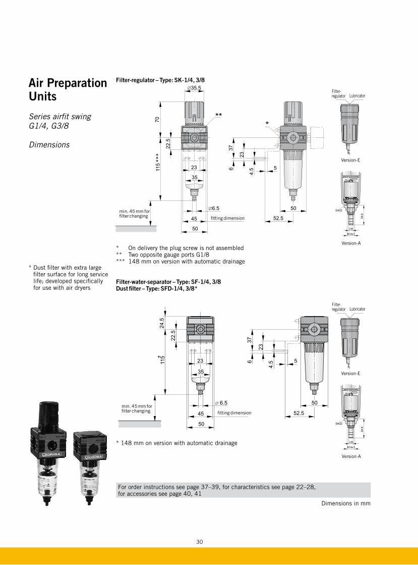
Filter-regulator – Type: SK-1/4, 3/8
* On delivery the plug screw is not assembled** Two opposite gauge ports G1/8*** 148 mm on version with automatic drainage
***
min. 45 mm for filter changing fitting dimension
For order instructions see page 37–39, for characteristics see page 22–28, for accessories see page 40, 41
Dimensions in mm
Filter-water-separator – Type: SF-1/4, 3/8 Dust filter – Type: SFD-1/4, 3/8*
* 148 mm on version with automatic drainage
��
����
�
��
���
���
����
���
����
��
��
��
�����
��
*
min. 45 mm for filter changing fitting dimension
Version-A
��
�����
����
����
�
�
��
����
�
��
���
���
����
�
����
��
��
��
���
���
�
��
Version-A
��
�����
����
����
�
�
��
����
�
��
���
���
����
�
����
��
��
��
���
���
�
��
Air Preparation Units
Series airfit swing G1/4, G3/8
Dimensions
* Dust filter with extra large filter surface for long service life; developed specifically for use with air dryers
Filter-regulator Lubricator
Version-E
Filter-regulator Lubricator
Version-E
31
For order instructions see page 37–39, for characteristics see page 22–28, for accessories see page 40, 41
Dimensions in mm
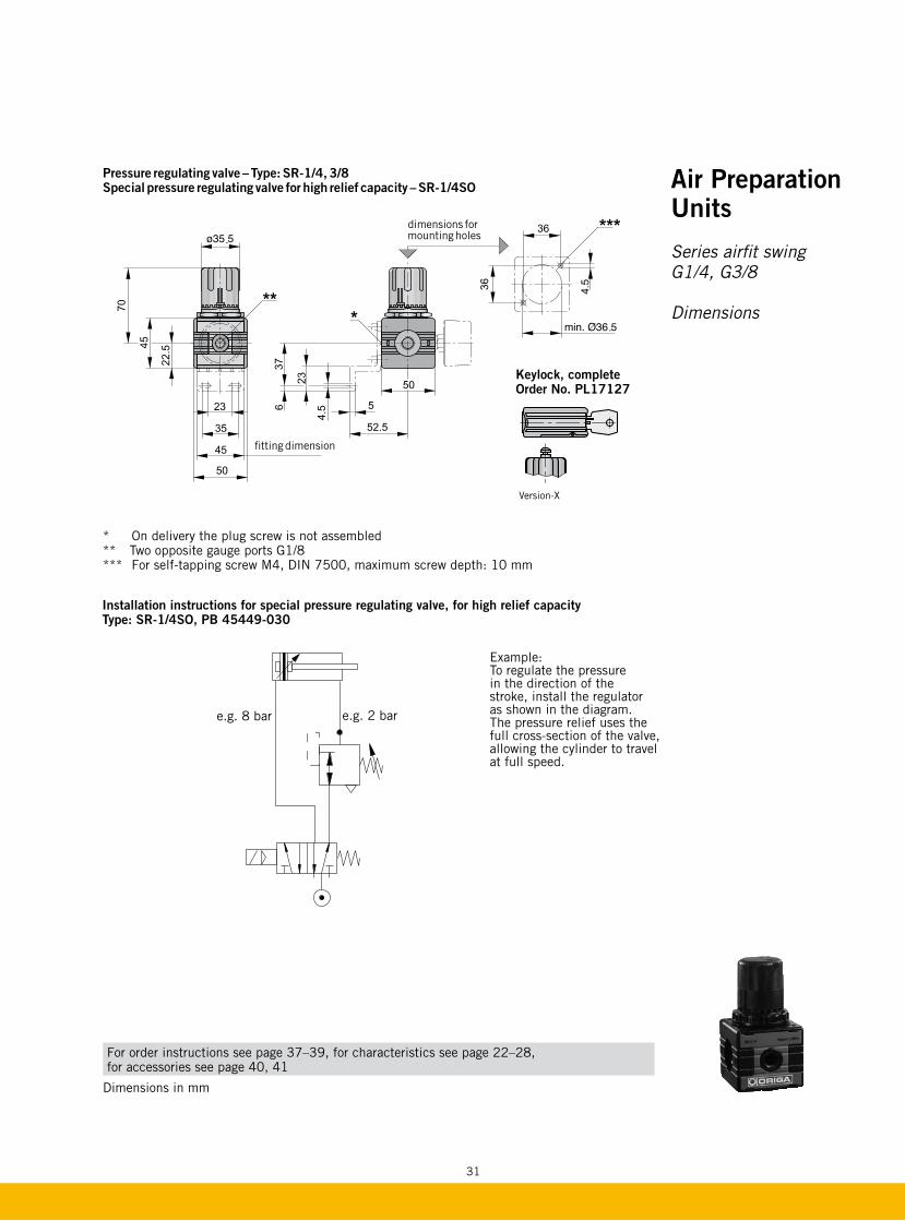
Pressure regulating valve – Type: SR-1/4, 3/8 Special pressure regulating valve for high relief capacity – SR-1/4SO
* On delivery the plug screw is not assembled** Two opposite gauge ports G1/8*** For self-tapping screw M4, DIN 7500, maximum screw depth: 10 mm
��
��
����
�
��
���
���
��
����
��
��
��
��
��
�
��
�� ���
���
�
�
������
����������
��
��
����
�
��
���
���
��
����
��
��
��
��
��
�
��
�� ���
���
fitting dimension
dimensions for mounting holes
Installation instructions for special pressure regulating valve, for high relief capacity Type: SR-1/4SO, PB 45449-030
e.g. 8 bar e.g. 2 bar
Example:To regulate the pressure in the direction of the stroke, install the regulator as shown in the diagram. The pressure relief uses the full cross-section of the valve, allowing the cylinder to travel at full speed.
Keylock, completeOrder No. PL17127
Air Preparation Units
Series airfit swing G1/4, G3/8
Dimensions
Version-X

32
Pressure regulating valve, with through p1 supply port – Type: SR-1/4-T, 3/8-T
* Gauge ports G1/8** With through p1 supply port G1/4, G3/8*** For self-tapping screw M4, DIN 7500, maximum screw depth: 10 mm**** p2 port G1/4
For order instructions see page 37–39, for characteristics see page 22–28, for accessories see page 40, 41
Dimensions in mm
Installation instructions for battery mounting
��������
����
����
����
����
����
����
����
��������
����
��������
����
��������
����
Air Preparation Units
Series airfit swing G1/4, G3/8
Dimensions �
��
��
��
����
��
��
��
��
�� ��
�
��
�� ���
����
�
dimensions for mounting hole
fitting dimension
****
**

33
Pressure regulating valve, pilot operated – Type: SRV-1/4
– Recommended pilot pressure regulating valve, series airfit light, Type: MRP-1/8, PB21749-800
* Two opposite gauge ports G1/8 – On delivery the plug screw is not assembled.
��
����
�
��
���
���
��
����
��
��
��
��
��
������
�
fitting dimension
For order instructions see page 37–39, for characteristics see page 22–28, for accessories see page 40, 41
Dimensions in mm
Oil mist lubricator – Type: SL-1/4, 3/8
��
����
�
��
���
���
����
��
����
��
��
��
��
��
fitting dimensionmin. 45 mm for filter changing
Oil refilling plug Oil adjusting screw
Version-E
Air Preparation Units
Series airfit swing G1/4, G3/8
Dimensions

34
For order instructions see page 37–39, for characteristics see page 22–28, for accessories see page 40, 41
Dimensions in mm
Stop valve – Type: SDR-1/4P, 3/8P (pneumatically actuated)
����
��
�
���
��
���
��
��
��
��
����
��
���
���
��
��
����
����
��
���
���� �
�
� �
��
fitting dimension
Installation instructions for start-stop valve
Pilot port:PneumaticG1/8
Stopvalve
Startvalve
Pilot port:PneumaticG1/8
Stopvalve
Startvalve
Start valve – Type: SDA-1/4, 3/8
��
����
�
��
���
���
��
����
��
��
��
��
��
������������������
fitting dimension
throttle screw
Air Preparation Units
Series airfit swing G1/4, G3/8
Dimensions
Features:
Safety valve for slow pressure build-up in pneumatic circuits. It prevents uncontrolled movements of the pneumatic components under the impact of full operating pressure. Pressure build-up time can be adjusted with the throttle screw.
Note:System operation must not be switched on during the starting phase.
The stop valve is used in conjunction with the soft start valve for exhausting pneumatic circuits.
Venting time (s) in relation to volumePressure reduction range
Venting time (s) *
8 → 0.1 bar 0.7 x V (l) = t (s)6 → 0.1 bar 0.65 x V (l) = t (s)4 → 0.1 bar 0.55 x V (l) = t (s)2 → 0.1 bar 0.45 x V (l) = 6 (s)* Notes:
This calculation assumes short connections with NW 8 mm tubing directly after the SDR stop valve.
35
For order instructions see page 37–39, for characteristics see page 22–28, for accessories see page 40, 41
Dimensions in mm
����
��
�
���
��
���
��
��
��
��
��
����
��
����
��
���
���
��
��
fitting dimension
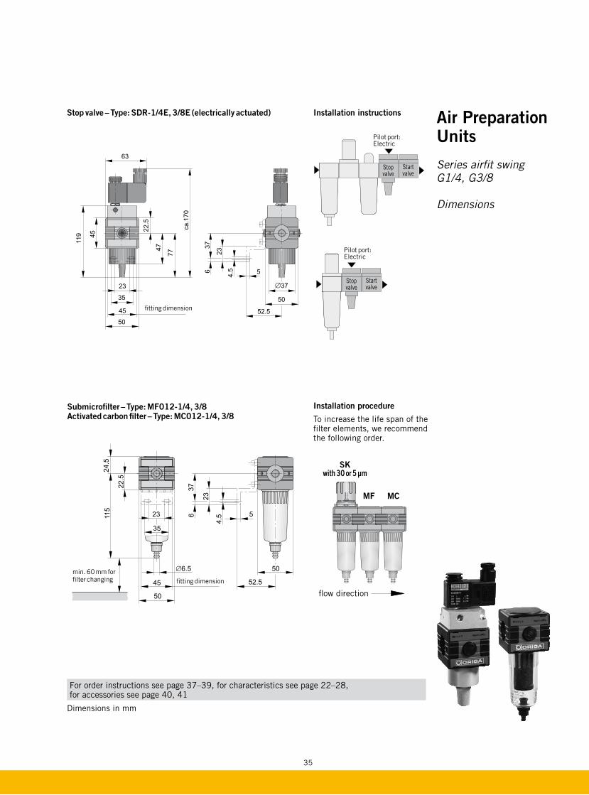
Submicrofilter – Type: MF012-1/4, 3/8 Activated carbon filter – Type: MC012-1/4, 3/8
��
����
�
��
���
���
����
���
����
��
��
��
����
��
fitting dimensionmin. 60 mm for filter changing
Installation procedure
To increase the life span of the filter elements, we recommend the following order.
SKwith 30 or 5 µm
MF MC
flow direction
Stop valve – Type: SDR-1/4E, 3/8E (electrically actuated) Installation instructions
Pilot port: Electric
Stopvalve
Startvalve
Pilot port: Electric
Stopvalve
Startvalve
Air Preparation Units
Series airfit swing G1/4, G3/8
Dimensions

36
���
����
����
����
�����
��
����
��
�
Air Preparation Units
Series airfit swing G1/4, G3/8
Dimensions
Features:
– Spool type valve– 3-piece lockable– Color coded optical
position indicator – Controlled exhaust– Arrow symbol indicates
flow direction
3/2 way shut-off valveType: SDV-1/4-XS, -3/8-XS
Dimensions in mm
For order instructions see page 37–39, for characteristics see page 22–28, for accessories see page 40, 41

37
Standard versions
Description Symbol Port size Order instruction
Type Order No.
Air preparation unit three-piece
Basic version G1/4 SFRL-1/4 PB 48149-000
G3/8 SFRL-3/8 PB 48249-000
with semi-automatic drainage G1/4 SFRL-1/4-H PB 48149-001
G3/8 SFRL-3/8-H PB 48249-001
with automatic drainage G1/4 SFRL-1/4-A PB 48149-002
G3/8 SFRL-3/8-A PB 48249-002
Air preparation unit two-piece
Basic version G1/4 SKL-1/4 PB 48449-000
G3/8 SKL-3/8 PB 48549-000
with semi-automatic drainage G1/4 SKL-1/4-H PB 48449-001
G3/8 SKL-3/8-H PB 48549-001
with automatic drainage G1/4 SKL-1/4-A PB 48449-002
G3/8 SKL-3/8-A PB 48549-002
with metal bowl (sight glass) 1) G1/4 SKL-1/4-E PB 48449-004
G3/8 SKL-3/8-E PB 48549-004
Filter-regulator
Basic version G1/4 SK-1/4 PB 45749-000
G3/8 SK-3/8 PB 45849-000
with filter element 5 µm G1/4 SK-1/4-5 PB 45749-016
G3/8 SK-3/8-5 PB 45849-016
with semi-automatic drainage G1/4 SK-1/4-H PB 45749-001
G3/8 SK-3/8-H PB 45849-001
with automatic drainage G1/4 SK-1/4-A PB 45749-002
G3/8 SK-3/8-A PB 45849-002
with metal bowl (sight glass) 1) G1/4 SK-1/4-E PB 45749-004
G3/8 SK-3/8-E PB 45849-004
Filter-water-separator
Basic version G1/4 SF-1/4 PB 45149-000
G3/8 SF-3/8 PB 45249-000
with filter element 5 µm G1/4 SF-1/4-5 PB 45149-016
G3/8 SF-3/8-5 PB 45249-016
with filter element 1 µm(dust filter)
G1/4 SFD-1/4-1 PB 45149-070
G3/8 SFD-3/8-1 PB 45249-070
with semi-automatic drainage G1/4 SF-1/4-H PB 45149-001
G3/8 SF-3/8-H PB 45249-001
with automatic drainage G1/4 SF-1/4-A PB 45149-002
G3/8 SF-3/8-A PB 45249-002
with metal bowl (sight glass) 1) G1/4 SF-1/4-E PB 45149-004
G3/8 SF-3/8-E PB 45249-004
Air Preparation Units
Series airfit swing G1/4, G3/8
Order instructions
1) Versions with metal bowl and automatic drainage on request

38
Standard versions
Description Symbol Port size Order instruction
Type Order No.
Pressure regulating valve
– Basic version G1/4 SR-1/4 PB 45449-000
G3/8 SR-3/8 PB 45549-000
– with adapter for keylock G1/4 SR-1/4-X PB 45449-006
G3/8 SR-3/8-X PB 45549-006
– Special pressure regulating valve for high relief capacity
G1/4 SR-1/4SO PB 45449-030
– Pressure regulating valve with through p1 supply port
p1-G1/4, throughp2-G1/4, Output
SR-1/4-T-1/4 PB 45449-100
– Pressure regulating valve with through p1 supply port
p1-G3/8, throughp2-G1/4, Output
SR-3/8-T-1/4 PB 45549-100
– Pressure regulating valve, pilot operated
G1/4 SRV-1/4 PB 45449-070
Oil mist lubricator
– Basic version G1/4 SL-1/4 PB 46149-000
G3/8 SL-3/8 PB 46249-000
– with metal bowl (sight glass)
G1/4 SL-1/4-E PB 46149-004
G3/8 SL-3/8-E PB 46249-004
Start valve
– Start valve G1/4 SDA-1/4 PB 47149-100
G3/8 SDA-3/8 PB 47249-100
Stop valve
– pneumatically actuated G1/4 SDR-1/4 P PB 47149-200
G3/8 SDR-3/8 P PB 47249-200
– electrically actuated 24 V DC
G1/4 SDR-1/4 E PB 47149-201
G3/8 SDR-3/8 E PB 47249-201
– electrically actuated 230 V/50 Hz
G1/4 SDR-1/4 E PB 47149-204
G3/8 SDR-3/8 E PB 47249-204
Air Preparation Units
Series airfit swing G1/4, G3/8
Order instructions
2
1
()
2
1 3
1012
2
1 3
1012

39
Standard versions
Description Symbol Port size Order instruction
Type Order No.
Submicrofilter
– Basic version G1/4 MF 012-1/4 PB 49149-000
G3/8 MF 012-3/8 PB 49249-000
– with metal bowl (sight glass)
G1/4 MF 012-1/4-E PB 49149-004
G3/8 MF 012-3/8-E PB 49249-004
Activated carbon filter
– Basic version G1/4 MC 012-1/4 PB 49449-000
G3/8 MC 012-3/8 PB 49549-000
– with metal bowl (sight glass)
G1/4 MC 012-1/4-E PB 49449-004
G3/8 MC 012-3/8-E PB 49549-004
3/2 way shut-off valve
– 3/2 way shut-off valve G1/4 SDV-1/4-XS PB 46749-101
– 3/2 way shut-off valve G3/8 SDV-3/8-XS PB 46849-101
Accessories
Description For type Order No.
Mounting kit Standard PL16965
Mounting kit SR-..T PL18519
Gauge Ø 40, 0–10 bar, G1/8*
SK, SR, SR-T KZ8813
Coupling kit PL16959
Porting block kit 3 x G1/8, 1 x G1/4 (coupling kit included)
PL16969
Porting block kit 3 x G1/8, 1 x G1/4 for pressure switch (mounting material included)
PL16977
Bowl guard kit PL16970-00
Keylock for pressure regulating valve SR-..X PL17127
Keylock for 3/2 way shut-off valve SDV KG9017
Solvent resistant sight glass SL PL07233
Special oil for oil mist lubricators 1 l (see page 203)
KY8766
* for more gauges see page 198, 199
For more information see accessories page 40, 41
Air Preparation Units
Series airfit swing G1/4, G3/8
Order instructions
2
1 3
12

40
Installation instructions
Order instructionsDescription Order instruction
Type Order No.
Porting block kit – standard G1/4 - G3/8 SX PL 16969
Porting block kit – for pressure switch mounting SXH PL16977
Porting block kit – NPTF 1/4 standard SX-US PL17826
50
35
28
42
45
∅12
∅2
4
G1/8
G1/4
35G
1/8*G1/4serienmäßigG1/4on both sidesG1/4je na obou
G1/4(G3/8 rear side)
Dimensions
* G1/8 thread on both sides
Characteristics Description
Installation Between 2 units of the airfit swing series
Mounting Directly flange mountable with coupling kit supplied
Material Zinc diecasting, black finish
e.g. Pressure switch or pressure relief valve
Filter-water-separator Pressure regulating valve Oil mist lubricator
Clean compressed air
Clean and regulated compressed air
Porting block
Filter-water-separatorPressure
regulating valve Porting block Oil mist lubricator
e.g. Pressure switch or pressure relief valve
Dimensions in mm
Air Preparation Units
Series airfit swing G1/4, G3/8
Accessories– Porting block kit
To provide unlubricated air e.g. for air gun
Versions:
– Standard– For pressure switch mounting
Delivery includes:
1 porting block1 coupling kit Plug screws
41
Air Preparation Units
Series airfit swing G1/4, G3/8
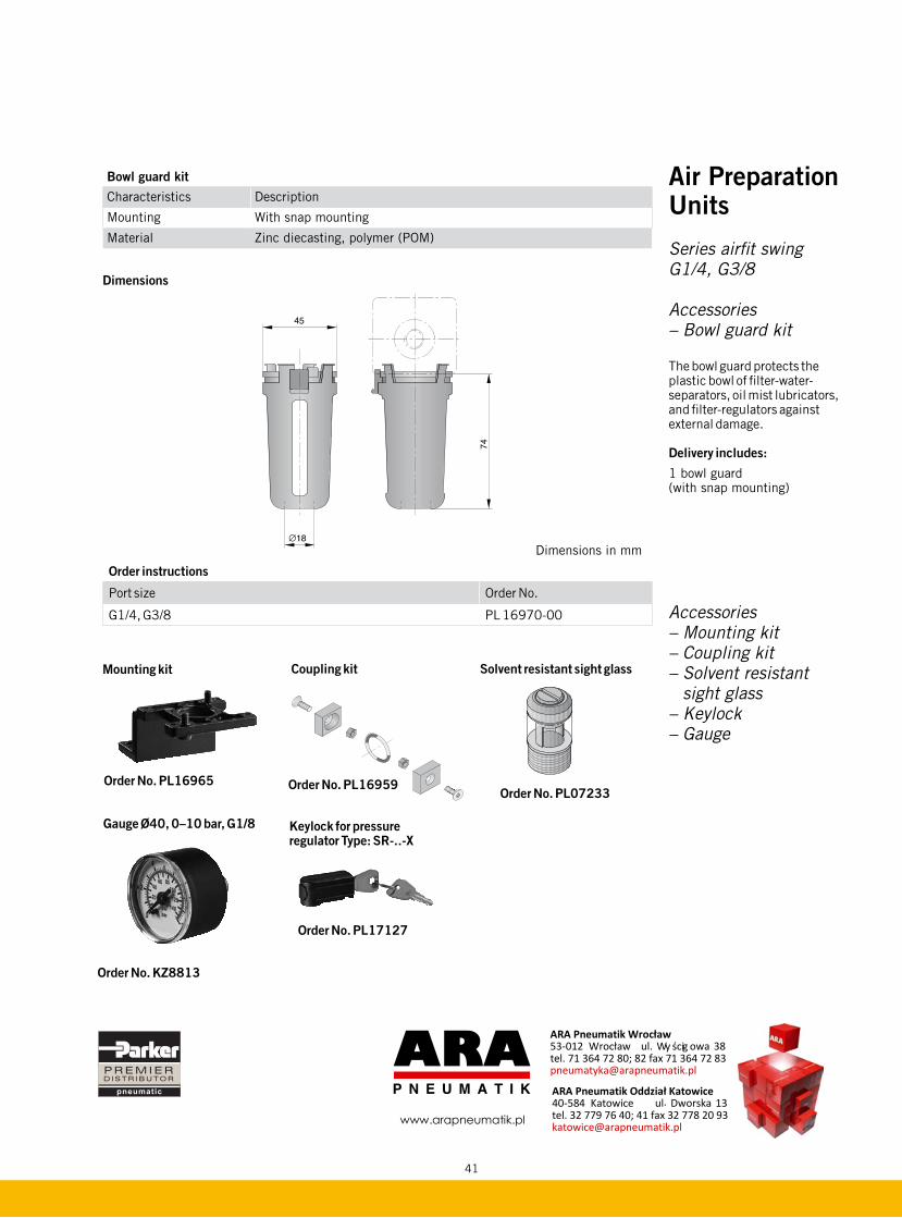
Accessories – Bowl guard kit
The bowl guard protects the plastic bowl of filter-water-separators, oil mist lubricators, and filter-regulators against external damage.
Delivery includes:
1 bowl guard (with snap mounting)
Accessories– Mounting kit– Coupling kit– Solvent resistant
sight glass– Keylock– Gauge
Order instructions
Port size Order No.
G1/4, G3/8 PL 16970-00
Bowl guard kit
Characteristics Description
Mounting With snap mounting
Material Zinc diecasting, polymer (POM)
Dimensions
Solvent resistant sight glass
Order No. PL07233
Keylock for pressure regulator Type: SR-..-X
Order No. PL17127
Coupling kit
Order No. PL16959
Mounting kit
Order No. PL16965
Gauge Ø40, 0–10 bar, G1/8
Order No. KZ8813
Dimensions in mm
pneumatic
www.arapneumatik.pl
ARA Pneumatik Wrocùaw 53-012 Wrocùaw ul. Wy �cig owa 38 tel. 71 364 72 80; 82 fax 71 364 72 83 [email protected]
ARA Pneumatik Oddziaù Katowice 40-584 Katowice ul. Dworska 13 tel. 32 779 76 40; 41 fax 32 778 20 93 [email protected]