air winchramwinch.com/wordpress/wp-content/uploads/2014/08/hu40-hul40...view of the hoist drum. do...
TRANSCRIPT

14603 CHRISMAN HOUSTON, TEXAS 77039 (281) 999-8665 FAX: (281) 999-8666 or (888) 726-5438
Instructions, Parts and Maintenance
AIR WINCH MODEL HU40 / HUL40
Page 1 of 2
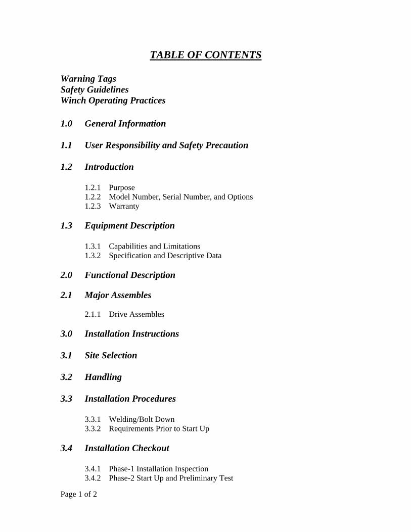
TABLE OF CONTENTS
Warning Tags Safety Guidelines Winch Operating Practices
1.0 General Information 1.1 User Responsibility and Safety Precaution 1.2 Introduction
1.2.1 Purpose 1.2.2 Model Number, Serial Number, and Options 1.2.3 Warranty 1.3 Equipment Description
1.3.1 Capabilities and Limitations 1.3.2 Specification and Descriptive Data 2.0 Functional Description 2.1 Major Assembles
2.1.1 Drive Assembles 3.0 Installation Instructions 3.1 Site Selection 3.2 Handling 3.3 Installation Procedures 3.3.1 Welding/Bolt Down 3.3.2 Requirements Prior to Start Up 3.4 Installation Checkout 3.4.1 Phase-1 Installation Inspection 3.4.2 Phase-2 Start Up and Preliminary Test

Page 2 of 2
3.5 Cable Installation 3.5.1 Cable Termination on Drum 3.5.2 Spooling Cable onto Drum 4.0 Operating Instructions
4.1 Operator Start Up 4.2 Shutdown 4.3 Brake Release Valve
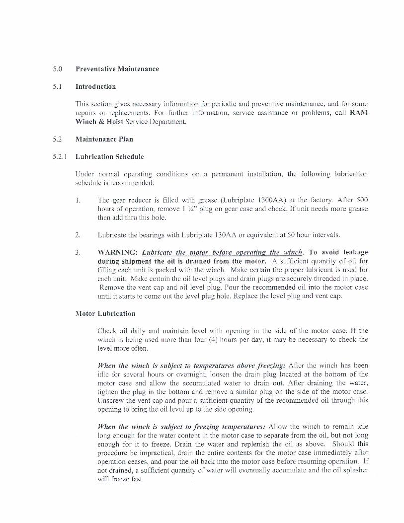
5.0 Preventive Maintenance 5.1 Introduction
5.2 Maintenance Plan 5.2.1 Lubrication Schedule 5.2.2 Cleaning 5.2.3 Cable and Hoses 5.2.4 Brake Adjustment 5.2.5 General Inspection
6.0 Component Removal/Replacement Appendices RAM Winch & Hoist Parts Information

! WARNING ! Failure to follow these warning signs may result in death, severe injury or property damage: Do not operate this hoist before reading the operation
and maintenance manual. Do not lift more than rated load. Do not allow less than three wraps of wire rope to
remain on drum at all times. Operator must stay in view of the hoist drum.
Do not operate a damaged or malfunctioning hoist. Do not remove or obscure warning labels.

GENERAL GUIDELINES FOR SAFE OPERATION
The following warnings and precautions should be taken to ensure safe operating conditions.
Failure to remain alert and keep equipment in good operating condition could result in personal injury or death. To avoid such please read and understand this manual as well as all applicable laws and requirements for safe operation.
Keep a copy of this manual with the equipment at all times.
Be certain all operators of the equipment have been properly trained in the use of the equipment and have read the owners manual thoroughly.
!!WARNING!!
Keep hands, feet and any loose clothing away from rotating or moving parts. Never operate the equipment with any guards or safety equipment removed from winch.
Failure to do so may result in injury or death.
When maintaining the equipment be sure to tag Out of Service on power supply to prevent accidental operation or activation.
Do not alter or modify the equipment in any way without first contacting RAM Winch & Hoist Engineering Department as to the alteration type or extent. Failure to do so could result in damage to the equipment or injury to personnel.

WIN
CH
OP
ER
AT
ING
PR
AC
TIC
ES
P
ost
at
Op
erat
ing
Sta
tio
n
Fo
rm 2
008
1.
Rea
d
the
man
ufa
ctu
rer'
s in
stru
ctio
ns
bef
ore
oper
atin
g th
e w
inch
. 2
. A
lway
s in
spec
t,
test
m
ain
tain
an
d
oper
ate
this
w
inch
in
ac
cord
ance
wit
h A
mer
ican
Nat
ion
al S
tan
dar
ds
Inst
itu
te S
afet
y S
tan
dar
ds
B30
.7.
3.
Nev
er L
ift
a lo
ad g
reat
er t
han
th
e ra
ted
lin
e p
ull
of
the
win
ch.
4.
Use
th
e re
com
men
ded
siz
e w
ire
rop
e fo
r lo
ad t
o b
e h
and
led
. 5
. N
ever
use
th
e w
ire
rop
e as
a s
lin
g.
6.
Alw
ays
stan
d c
lear
of
the
load
. 7
. U
nle
ss t
he
win
ch i
s d
esig
ned
for
per
son
nel
han
dli
ng,
nev
er u
se
the
win
ch f
or l
ifti
ng
or l
ower
ing
peo
ple
, an
d n
ever
sta
nd
on
a
susp
end
ed lo
ad.
8.
Nev
er c
arry
load
s ov
er p
eop
le.
9.
Nev
er d
isen
gage
th
e cl
utc
h w
ith
a lo
ad a
pp
lied
to
the
win
ch.
10.
Nev
er e
nga
ge t
he
clu
tch
wit
h t
he
win
ch m
otor
ru
nn
ing.
11
. A
lway
s ri
g th
e w
inch
pro
per
ly a
nd
car
efu
lly,
mak
ing
cert
ain
th
e w
ire
rop
e is
pro
per
ly a
nch
ored
to
the
dru
m.
12.
Bef
ore
each
sh
ift,
ch
eck
th
e w
inch
for
wea
r or
dam
age.
C
hec
k
the
bra
kes
, w
ire
rop
e, h
ook
s, g
uid
es,
mou
nti
ng
bol
ts,
etc.
L
ift
a ca
pac
ity
load
or
a n
ear
cap
acit
y lo
ad a
few
in
ches
off
th
e fl
oor
and
ch
eck
th
e ab
ilit
y of
th
e b
rak
ing
syst
em t
o st
op a
nd
hol
d t
he
load
wit
hou
t ex
cess
ive
dri
ft, i
f th
e w
inch
is b
ein
g u
sed
for
lift
ing.
13
. N
ever
op
erat
e a
win
ch w
ith
a t
wis
ted
, k
ink
ed o
r d
amag
ed w
ire
rop
e.
14.
Per
iod
ical
ly i
nsp
ect
the
win
ch t
hor
ough
ly a
nd
rep
lace
wor
n o
r d
amag
ed p
arts
. K
eep
acc
ura
te r
ecor
ds
of a
ll i
nsp
ecti
ons
and
re
pai
rs.
15.
Fol
low
th
e lu
bri
cati
on
inst
ruct
ion
s p
rovi
ded
b
y th
e m
anu
fact
ure
r.
16.
Do
not
att
emp
t to
rep
air
the
wir
e ro
pe
or h
ook
s.
Rep
lace
hoo
ks
wh
en t
her
e is
a 1
5% in
crea
se in
th
e th
roat
op
enin
g or
wh
en t
her
e is
a 1
0% b
end
as
show
n b
y in
spec
tion
rec
ord
s.
17.
Kee
p t
he
rop
e cl
ean
an
d w
ell
lub
rica
ted
. R
epla
ce w
ire
rop
e th
at
is f
raye
d.
18.
Eas
e th
e sl
ack
ou
t of
th
e w
ire
rop
e w
hen
sta
rtin
g.
Do
not
jer
k
the
win
ch.
19.
If t
he
dru
m i
s ex
pos
ed t
o p
erso
nn
el w
alk
way
s, p
lace
a g
uar
d
over
th
e d
rum
. 20
. D
o n
ot u
se y
our
han
ds
to g
uid
e th
e ro
pe
onto
th
e d
rum
wh
en
win
din
g in
th
e w
ire
rop
e.
21.
Be
cert
ain
th
ere
are
no
obje
cts
in t
he
way
of
the
load
or
hoo
k
wh
en o
per
atin
g th
e w
inch
. 22
. D
o n
ot
use
h
igh
er
air
pre
ssu
re
than
reco
mm
end
ed
by
the
man
ufa
ctu
rer.
23
. U
se c
omp
ress
ed a
ir c
aref
ull
y.
Be
sure
th
e h
ose
cou
pli
ngs
are
se
cure
, an
d m
ake
cert
ain
a s
afet
y ch
ain
is p
rovi
ded
to
avoi
d h
ose
wh
ip if
th
e co
up
lin
g fa
ils.
24
. W
ear
pro
per
cl
oth
ing
to
avoi
d
enta
ngl
emen
t in
ro
tati
ng
mac
hin
ery.
25
. B
e ce
rtai
n
the
air
sup
ply
is
sh
ut
off
bef
ore
per
form
ing
mai
nte
nan
ce o
n t
he
win
ch.
26.
Pro
per
ly s
ecu
re a
win
ch b
efor
e le
avin
g it
un
atte
nd
ed.
27.
Do
not
lea
ve a
loa
d s
usp
end
ed f
or a
ny
exte
nd
ed p
erio
d o
f ti
me.
N
ever
leav
e a
susp
end
ed lo
ad u
nat
ten
ded
. 28
. D
o n
ot a
llow
un
qu
alif
ied
per
son
nel
to
oper
ate
a w
inch
. 29
. D
o n
ot o
per
ate
a w
inch
if y
ou a
re n
ot p
hys
ical
ly f
it t
o d
o so
. 30
. D
o n
ot d
iver
t yo
ur
atte
nti
on f
rom
th
e lo
ad w
hil
e op
erat
ing
a w
inch
. 31
. B
e ce
rtai
n t
he
load
is
pro
per
ly s
eate
d i
n t
he
sad
dle
of
the
hoo
k.
Do
not
tip
loa
d t
he
hoo
k a
s th
is l
ead
s to
sp
read
ing
and
eve
ntu
al
fail
ure
of
the
hoo
k.
32.
Do
not
for
ce a
hoo
k in
to p
lace
by
ham
mer
ing.
33
. N
ever
op
erat
e a
win
ch b
eyon
d t
he
poi
nt
wh
ere
less
th
an f
our
wra
ps
of w
ire
rop
e re
mai
n o
n t
he
dru
m.
34.
Do
not
use
th
e w
ire
rop
e as
a g
rou
nd
for
wel
din
g.
Do
not
att
ach
a
wel
din
g el
ectr
ode
to a
win
ch o
r sl
ing.
35
. N
ever
op
erat
e a
win
ch t
hat
mak
es e
xces
sive
mec
han
ical
noi
se.
Rep
ort
the
pro
ble
m im
med
iate
ly.

1.0 General Information 1.1 User Responsibility and Safety Precautions This equipment will perform in conformity with the description thereof, contained in this manual, its accompanying labels and/or inserts when it is installed, operated, maintained and repaired according to the instructions provided. This equipment must be maintained properly. Deficient equipment should not be used. Parts that are broken, missing, plainly worn, distorted or contaminated should be replaced immediately. Should such repair or replacement become necessary, we recommend that a telephone or written request for service be made to RAM Winch & Hoist. This equipment or any of its parts should not be altered without prior written approval of RAM Winch & Hoist. The user of this equipment shall have the sole responsibility for any malfunction that results from improper use, faulty maintenance, damage, improper repairs or alterations made by anyone other than RAM Winch & Hoist. 1.2 Introduction 1.2.1 Purpose The purpose of this manual is to provide installation, operating and maintenance instructions and procedures for your RAM Winch & Hoist. 1.2.2 Model Number, Serial Number and Options This manual covers the hoist built by RAM Winch & Hoist for your particular unit. The model number and serial number are listed on the nameplate attached to the unit. 1.2.3 Warranty See standard warranty certificate. 1.3 Equipment Description 1.3.1 Capabilities and Limitations The winch is an air, planetary driven cable-handling unit with manual release band brake designed for use in the marine or industrial environment.
2.0 Functional Description

2.1 Major Assemblies
The hoist consists of the following major assemblies:
a. Drive assembly. b. Frame and drum assembly.
3.0 Installation Instruction
3.1 Site Selection
The winch should be installed in a location that meets the following requirements: Firm foundation that allows the unit to be welded or bolted down to withstand a
minimum of 5 times the rated line pull of the hoist.
Accessibility for the operator.
Protection from heavy falling objects.
Near an adequate air supply source.
As far as possible from the first turn sheave.
Out of the way of other operations.
3.2 Handling Lifting the unit on the topside of the frame (via lifting eyes) will accommodate standard lifts. The unit may also be lifted from under the base by a forklift.
WARNING DO NOT LIFT HOIST BY CABLE DRUM -DAMAGE TO CABLE AND/OR BRAKE
ASSEMBLY MAY RESULT.


RAM AIR WINCH PARTS
When ordering parts, please have the model number and serial number for your unit. If possible, please supply us with the original purchase order number.
See the following pages for part ordering information.
Please call (281) 999-8665 or fax an order to (281) 999-8666.

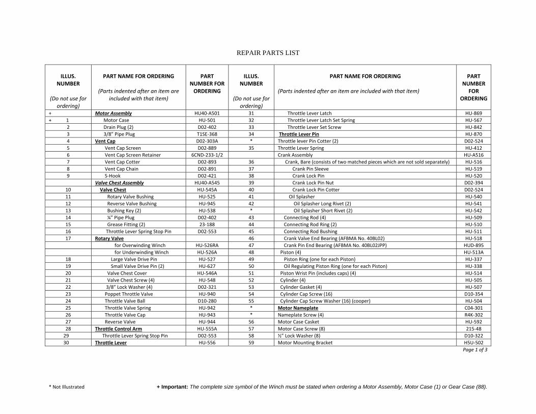
* Not Illustrated + Important: The complete size symbol of the Winch must be stated when ordering a Motor Assembly, Motor Case (1) or Gear Case (88).
REPAIR PARTS LIST
ILLUS.
NUMBER
(Do not use for ordering)
PART NAME FOR ORDERING
(Parts indented after an item are
included with that item)
PART
NUMBER FOR ORDERING
ILLUS.
NUMBER
(Do not use for ordering)
PART NAME FOR ORDERING
(Parts indented after an item are included with that item)
PART
NUMBER FOR
ORDERING
+ Motor Assembly HU40‐A501 31 Throttle Lever Latch HU‐869+ 1 Motor Case HU‐501 32 Throttle Lever Latch Set Spring HU‐567
2 Drain Plug (2) D02‐402 33 Throttle Lever Set Screw HU‐8423 3/8” Pipe Plug T1SE‐368 34 Throttle Lever Pin HU‐8704 Vent Cap D02‐303A * Throttle lever Pin Cotter (2) D02‐5245 Vent Cap Screen D02‐889 35 Throttle Lever Spring HU‐4126 Vent Cap Screen Retainer 6CND‐233‐1/2 Crank Assembly HU‐A5167 Vent Cap Cotter D02‐893 36 Crank, Bare (consists of two matched pieces which are not sold separately) HU‐5168 Vent Cap Chain D02‐891 37 Crank Pin Sleeve HU‐5199 S‐Hook D02‐421 38 Crank Lock Pin HU‐520 Valve Chest Assembly HU40‐A545 39 Crank Lock Pin Nut D02‐394
10 Valve Chest HU‐545A 40 Crank Lock Pin Cotter D02‐52411 Rotary Valve Bushing HU‐525 41 Oil Splasher HU‐54012 Reverse Valve Bushing HU‐945 42 Oil Splasher Long Rivet (2) HU‐54113 Bushing Key (2) HU‐538 * Oil Splasher Short Rivet (2) HU‐54214 ¼” Pipe Plug D02‐402 43 Connecting Rod (4) HU‐50915 Grease Fitting (2) 23‐188 44 Connecting Rod Ring (2) HU‐51016 Throttle Lever Spring Stop Pin D02‐553 45 Connecting Rod Bushing HU‐51117 Rotary Valve 46 Crank Valve End Bearing (AFBMA No. 40BL02) HU‐518 for Overwinding Winch HU‐526RA 47 Crank Pin End Bearing (AFBMA No. 40BL02JPP) HUD‐895 for Underwinding Winch HU‐526A 48 Piston (4) HU‐513A
18 Large Valve Drive Pin HU‐527 49 Piston Ring (one for each Piston) HU‐33719 Small Valve Drive Pin (2) HU‐627 50 Oil Regulating Piston Ring (one for each Piston) HU‐33820 Valve Chest Cover HU‐546A 51 Piston Wrist Pin (includes caps) (4) HU‐51421 Valve Chest Screw (4) HU‐548 52 Cylinder (4) HU‐50522 3/8” Lock Washer (4) D02‐321 53 Cylinder Gasket (4) HU‐50723 Poppet Throttle Valve HU‐940 54 Cylinder Cap Screw (16) D10‐35424 Throttle Valve Ball D10‐280 55 Cylinder Cap Screw Washer (16) (cooper) HU‐50425 Throttle Valve Spring HU‐942 * Motor Nameplate C04‐30126 Throttle Valve Cap HU‐943 * Nameplate Screw (4) R4K‐30227 Reverse Valve HU‐944 56 Motor Case Casket HU‐59228 Throttle Control Arm HU‐555A 57 Motor Case Screw (8) 215‐48
29 Throttle Lever Spring Stop Pin D02‐553 58 ½” Lock Washer (8) D10‐322 30 Throttle Lever HU‐556 59 Motor Mounting Bracket H5U‐502
Page 1 of 3

* Not Illustrated + Important: The complete size symbol of the Winch must be stated when ordering a Motor Assembly, Motor Case (1) or Gear Case (88).
ILLUS.
NUMBER
(Do not use for ordering)
PART NAME FOR ORDERING
(Parts indented after an item are included with
that item)
PART
NUMBER FOR
ORDERING
ILLUS. NUMBER
(Do not use for
ordering)
PART NAME FOR ORDERING
(Parts indented after an item are included with
that item)
PART
NUMBER FOR
ORDERING
* Rope Instruction Plate DU‐32 89 Gear Case Cover Dowel D02‐347* Instruction Plate Screw (4) R4K‐302 90 Gear Case Cover HU40‐35260 Rope Drum 91 Gear Case Cover Screw (14) D10‐312A for Size H40 H40‐324 92 3/8” Lock Washer (18) D02‐321 for Size HUL40 HUL40‐324 93 Grease Plug (2) 22SR‐165
61 Wire Rope Set Screw (2) HU‐381 94 Brake Lever 23‐71562 Drum Packing HU‐866 95 Brake Lever Short Bolt (2) 23‐71763 Drum Bearing (2) (Hyatt C99211 or its equivalent) HU‐466 * Brake Lever Bolt Nut (2) D02‐41864 Drum Bearing Spacer 97 Brake Bracket Pin 107‐147 for Size HU40 HU‐467 98 Brake Adjusting Screw 23‐719 for Size HUL40 HUL‐467 99 Brake Trunnion HU40‐721
65 Drum Bearing Plate (2) HU‐469 100 Brake Adjusting Nut D02‐90466 Drum Shaft 101 Short Brake Band HU40‐152 for Size HU40 HU‐459 102 Short Brake Lining HU40‐155 for Size HU40 HUL‐459 103 Brake Lining Long Rivet (6) 235‐98
67 Drum Shaft Short Set Screw HU‐867 104 Brake Lining Short Rivet (7) 207‐35368 Drum Shaft Long Set Screw HU‐868 105 Long Brake Band HU40‐25269 Motor Shaft 106 Long Brake Lining HU40‐252 for Size HU40 HU40‐316 107 Brake Lining Long Rivet (6) 235‐98 for Size HUL40 HUL40‐316 108 Brake Lining Short Rivet (17) 207‐353
70 Motor Pinion Key D04‐320 109 Brake Support HU40‐16171 Motor Shaft Pinion HU‐319A 110 Brake Support Pin or Brake Anchor (3) HU40‐20672 Motor Shaft Pinion Space HU40‐397 111 Cotter (8) D02‐33073 Motor Shaft Inner Bearing (AFBMA No. 35BC02) D10‐518 112 Base 74 Motor Shaft Outer Bearing (AFBMA No. 25BC02) G7‐24 for Size HU40 HU‐564A75 Motor Shaft Bearing Screw D02‐361 for Size HUL40 HU‐564A76 Intermediate Gear HU40‐358 113 Base Bolt (8) HUL‐564A78 Intermediate Gear Bearing (2) (AFBMA No. 30BC03) 215‐55 114 Base Bolt Nut (8) HU40‐77579 Drive Shaft HU40‐358 115 Base Bolt Lock Washer (8) A‐6780 Drive Gear Key 23‐70 * Winch Nameplate DU‐30181 Drive Gear HU40‐357 * Nameplate Screw (4) R4K‐30282 Driver Gear Spacer HU40‐356 * Caution Tag TA‐147A83 Drive Shaft Outer Baring (AFBMA No. 30BC03) 215‐55 * Caution Tag Screw (4) R4K‐30284 Drive Shaft Inner Bearing (AFBMA No. 40BL03JP) HU‐359
85 Fiber Washer HU‐871
86 Drive Shaft Nut 215‐65
87 Drive Shaft Nut Lock 215‐66
88 Gear Case HU40‐353 Page 2 of 3

* Not Illustrated + Important: The complete size symbol of the Winch must be stated when ordering a Motor Assembly, Motor Case (1) or Gear Case (88).
MAINTENANCE TOOLS
TOOL NUMBER FOR ORDERING
TOOL NAME FOR ORDERING
OPERATION
P25-228 Grease Gun Lubrication D02-426 Wire Rope Set Screw Wrench Loosening or tightening the Wire Rope Set
Screws (61) in the Rope Drum (60).
HU-932 Jack Bolt (2 required) Removing the Valve Chest (10) from the Motor Case (1).
HU-933 Piston Ring Compressor Compressing the Piston Rings (49 and 50) when installing the Cylinder (52).
23470 Throttle Valve Stem Reamer Reaming the throttle valve stem hole in Reverse Valve Bushing (12) after installing a new Bushing.
25673 Throttle Valve Seat Reamer Smoothing the seat in the Valve Chest (10) for the Poppet Throttle Valve (23).
Page 3 of 3

MAINTENANCE INSTRUCTIONS
Apply the Wire Rope to wind on the Rope Drum in the direction indicated by the instruction plate on the Winch.
Rotate the Brake Adjusting Nut (100) to adjust the brake.
Remove the Throttle Valve Spring (25), Poppet Throttle Valve (23) and Throttle Valve Ball (24) from the Valve Chest (10) before attempting to withdraw the Reverse Valve (27) from the Reverse Valve Brushing (12).
The following procedure is recommended when replacement of the Rotary Valve Bushing (11) or Reverse Valve Bushing (12) is necessary:
1. Unscrew the Valve Chest Screws (21) and remove the Valve Chest Cover (20).
2. Screw A NO. HU-932 Jack Bolt into each tapped lug on the Valve Chest (10) until the Jack Bolts contact the Motor Case (1), then turn each one a little at a time to jack the Chest with assembled parts from the Motor Case.
3. Unscrew the Throttle Valve Cap (26) and remove the Spring (25), Poppet Throttle Valve (23) and Ball (24) from the Valve Chest (10).
4. Withdraw the Rotary Valve (17), Reverse Valve (27) and remove the Throttle Lever Spring (35).
5. Support the face of the Valve Chest (10) that contacts the Motor Case (1) and press out the old Bushing with an arbor that will clear the Bushing Keys (13). Caution:
6. 7. Failure to use an arbor that will clear the Bushing Keys
(13), or pressing the Bushings in the opposite direction than instructed will destroy the Keys.
8. Support the face of the Valve Chest (10) that contacts the Valve Chest Cover (20), align the keyslot in the new Reverse Valve Bushing with the Bushing Key (13) and press the Bushing into the Chest until the leading face of the Bushing is flush with the supported face of the Chest. Align the keyslot in the new Rotary Valve Bushing with the Bushing Key and press the Bushing into the Chest until the bushing shoulder is flush with the supported face of the Chest.
9. Insert the No. 23470 Throttle Valve Stem Reamer or a .505” (12.8 mm) hand reamer through the throttle valve chamber in the Valve Chest and ream the hole through the wall of the new Reverse Valve Bushing.
10. Check the fit of the Rotary Valve (17) in the new Rotary Valve Bushing. If the Valve is tighter than a good running fit in the Bushing, lap in the Valve using a fine grain lapping compound whose abrasive agent will break up rapidly. Remove all trace of the compound with kerosene after obtaining the desired fit.
11. Check the fit of the Reverse Valve (27) in the new Reverse Valve Bushing. If he fit a too tight, ream the Bushing 1.750”. Caution: The Reverse Valve is chrome plated; do not lap.
12. Rotate the Reverse Valve in the Reverse Valve Bushing until the arrows on the two parts align, and install the Throttle Valve Ball, Poppet Throttle Valve, Spring and Cap.
13. Install the Throttle Lever Spring (35) and Throttle Control Arm (28).
14. Align the holes through the Valve Chest (10) with those in the face of Motor Case (1) and squarely start the protruding end of the rotary Valve Bushing into the Case. Place a hardwood block on the chest face and press or drive in the Bushing until the Valve chest contacts the Motor Case.
The two sections of the Crank (36) are matched before final machining, and the web of each section is stamped with an identification mark as AA17, CC21, XX19, etc. Only sections bearing identical markings can be used together. If more than one Crank is disassembled at one time, be sure only matched parts are assembled together.
Slide the Crank Pin Sleeve (37), plain end first, onto the crank pin when assembling the Crank (36).
Install the Connecting Rod Rings (44) so that the internally beveled ends are toward the Connecting Rods (43) when assembling the Crank (36).
REPAIR PARTS
To keep costly downtime to a minimum, it is desirable to have on hand certain repair parts. To guide you in the stocking of repair parts, certain Illustration Numbers of the Repair Part List are marked with a bullet (●). We recommend that with parts so indicated, you stock one (pair or set) repair part for every four tools in service.

RAM WINCH & HOIST HUL40 7/2011
MODEL HU40 / HUL40 RAM WINCH & HOIST 05/14