air leakage of furnaces and air handlers
TRANSCRIPT

Air Leakage of Furnaces and Air Handlers
Iain S. Walker, Darryl Dickerhoff, and Woody Delp, Lawrence Berkeley National Laboratory Mike Lubliner, Washington State University
ABSTRACT In recent years, great strides have been made in reducing air leakage in residential and to
a lesser extent small commercial forced air duct systems. Several authorities have introduced low leakage limits for thermal distribution systems; for example, the State of California Energy Code for Buildings gives credit for systems that leak less than 6% of the total air flow at 25 Pa. Practitioners have found that a significant barrier to meeting specifications like this is the air leakage of the furnace or air handler itself. Anecdotal evidence exists for the magnitude of the air leakage of furnaces and air handlers. The states of California and Florida include air leakage limits for the furnaces in their State Building Energy Codes. However, there is currently no standard test method for measuring this air leakage that could be used for uniform and reliable ratings. This paper presents the results of laboratory measurements air leakage testing of furnaces and air handlers. The results indicate that average air leakage is significant - confirming existing anecdotal evidence. Also, the air leakage has a wide range from furnace to furnace indicating that low levels of air leakage are already attainable with existing equipment and the rating for air leakage will be able to distinguish between good and poorly performing equipment. This paper will also discuss the development of a standard test procedure (ASHRAE Standard 193 "Method of Test for Determining the Airtightness of HVAC Equipment") that will be used by Federal, State and Local code authorities and efficiency programs as well as appliance standards, utility programs and a range of other applications.
Introduction
The air leakage of heating, ventilating, and air conditioning (HVAC) equipment has two
major issues of interest:
1. Energy waste from air leakage. 2. Indoor Air Quality (IAQ) issues due to drawing air from crawlspaces, basements and
garages. It would be useful for codes and standards to specify tighter forced air system equipment
to supplement existing duct tightness requirements. It would also allow IAQ issues to be addressed in a simple fashion by requiring tight equipment as well as ducting in places outside conditioned space.
One of the most important predictors of a building’s energy efficiency is its HVAC system. There are a number of ways to measure the performance of HVAC systems—energy efficiency ratings being one of the most common—but the airtightness of the equipment is obviously an important factor as well. Air that is not delivered to areas as specified in the
1-330©2010 ACEEE Summer Study on Energy Efficiency in Buildings

building design is air that is not being used efficiently. Also, air drawn from unintended areas may bring in pollutants and result in poor indoor air quality. In recent years, much effort has gone into the sealing of the ducts in HVAC systems; however, air leakage still remains in the heating and cooling equipment itself and is a barrier to achieving tight systems.
Currently, the need for minimizing air leakage in HVAC systems is reflected in various ASHRAE standards. ASHRAE Standard 62.2 (2007) limits allowable air leakage between garages and houses due to leaks in forced air HVAC systems. ASHRAE Standard 152 (2004) includes HVAC system air leakage in estimates of distribution system efficiency for residential buildings. But while these standards aim to reduce the overall air leakage found in HVAC systems, neither provides a way to determine the effectiveness of specific components in an HVAC system in preventing air leakage.
Example methods for testing forced air system leakage can be found in ASTM E1554 (ASTM 2007), ASHRAE 152 (ASHRAE 2004), quality control programs such as those used by the US Department of Energy’s DOE Building America teams, and numerous utility programs. California Building Standards currently use a variation of the test found in ASHRAE 152 and ASTM E1554 in section RA 3.1.4.3 of the California Building Energy Code Joint Appendixes (CEC 2008b). The most common metric for estimating residential forced air system leakage is an air flow at a pressure difference of 25 Pa (0.1 in. water), because this metric is often used in field testing to meet the requirements of energy efficiency programs.
Currently, the State of Florida is the only entity attempting to legislate on the issue of furnace leakage. Florida Building Code section 610.2.A.2.1 (2003) specifies a pressurization test with the metric that the furnace (the Florida requirements apply to furnaces only) cannot leak more than 2% of blower air flow at 250 Pa (1 in. water), so a furnace or air handler with a nominal air flow of 500 L/s (1000 cfm) must have less than 10 L/s (20 cfm) of air leakage measured at 250 Pa (1 in. water). However, no specific test procedure is provided and there is no consistency between ratings of different pieces of equipment. Because the test procedures are not standardized, there is concern from both regulators and equipment manufacturers about having a consistent basis for comparison or a “level playing field”. When developing a new test standard there is a need to balance the manufacturers desire for simplicity of testing with a reasonable amount of rigor wanted by legislators and technical experts.
In the new California Building Energy code (CEC (2008a)), there is a credit for having a tight air handler defined in Section 3.12.5 as a furnace with less than 2% air leakage at 250 Pa (1 in. water). This is the same as the Florida requirement. Like the Florida code, the California code does not specify how to do the test to ensure consistency of testing between different pieces of equipment.
In Florida, actual test results are not reported. Instead, a list of complying equipment is provided by manufacturers to the state. Some furnaces come with certification that they meet air leakage specifications. An example from one manufacturer states “Airflow leakage less than 1% of total airflow at ductblaster conditions.” It is unclear, however, what “ductblaster conditions” means. Another example from another manufacturer’s product literature states “Factory sealed to achieve 2% or less leakage rate”. It does specify a test pressure of 250 Pa (1 in. water), but not specific test procedures. This lack of clarity and uniformity of testing is one of the reasons why a standard method of test is needed to produce a consistent test method for the industry to use.
1-331©2010 ACEEE Summer Study on Energy Efficiency in Buildings

To address this issue, a new standard method of test has been developed by ASHRAE: ASHRAE Standard 193 "Method of Test for Determining the Air Leakage of HVAC Equipment". This paper examines potential leak testing methods evaluated for inclusion in the new standard and discusses the development of the test method used in the standard.
Targeted at systems that move less than 1500 L/s (3000 cfm), Standard 193 will provide results that may be used by cognizant authorities who wish to regulate the air leakage of HVAC equipment, by contractors and installers that wish to specify and install equipment with known leakage characteristics, and by HVAC manufacturers who wish to verify and ensure that their approaches to reducing the air leakage of their equipment is successful. The approach taken in Standard 193 is to determine the air leakage rate of HVAC equipment at a fixed reference pressure difference. In this way, Standard 193 is similar to other rating standards that perform evaluations at a single test condition for comparison purposes rather than attempting to estimate performance for an individual installation.
Previous Studies
Concern about residential HVAC component leakage has been an issue for more than 10
years. Walker et al. (1998) measured six furnaces in a field study and found an average of 11 L/s (23 cfm) at 25 Pa (0.1 in. water) or 16 L/s (34 cfm) at operating pressures measured in the furnace outlet and blower compartment. This study also showed a large system-to-system variation with a standard deviation of 8 L/s (17 cfm) and a range of 3 to 24 L/s (6 to 51 cfm) at 25 Pa (0.1 in. water). The furnace leakage represented 24% to 76% of total system air leakage. More recently, other researchers have performed field testing of residential HVAC equipment air leakage. The Florida Solar Energy Center (FSEC) measured air handler leakage in a study of 69 Florida houses (Cummings et al. 2003). The air leakage from air handler/furnace cabinets was a significant fraction of total leakage from the tested systems: an average of 33 L/s (70 cfm) at estimated operating pressure.
Building Science Corporation (BSC) provided to the ASHRAE Standard 193 committee an overview of a study they conducted in Las Vegas, NV in 1999 in which they worked with large home builders to reduce forced air system air leakage. The air handlers had a leakage of 22 to 28 L/s (45 to 60 cfm) at 25 Pa (0.1 in. water), about half of which was the furnace and the remainder in coil boxes and plenums. Smoke tests were used by BSC to determine leak locations. In the air handlers, the most significant leaks occurred at the partition between the blower compartment and the wiring compartment (especially corners), and around the blower compartment door. BSC stated that “These problems should be correctable with gaskets and/or improved design.”
As a follow-up to the BSC tests, Guaranteed Watt Saver Systems (GWSSI) performed air handler unit (AHU) leakage tests in a laboratory. The GWSSI tests were conducted on AHU equipment more commonly used by builders in Oklahoma and Texas. AHU-alone leakage (at 25 Pa (0.1 in. water)) for the seven units tested ranged from 8 to 17 L/s (18 to 35 cfm). Converting both the BSC and GWSSI results to operating conditions (125 Pa (0.5 in. water)) gives results in the 19 to 33 L/s (40 cfm to 70 cfm) range similar to those observed in the field studies. GWSSI tested one unit in both horizontal and vertical configurations. The test results showed a factor of two difference in air leakage. GWSSI observed that “the different weight distribution of the
1-332©2010 ACEEE Summer Study on Energy Efficiency in Buildings

AHU components results in excessive cabinet deflection(s) between supports when placed in the horizontal position. This causes extra openings in the cabinet’s metal folds and seams for air leakage.”
Evaluation of Test Methods for Standard 193
A total of five test methods were evaluated. The first two test methods use the same
principles as other building component air leakage tests:
1. Whole furnace pressurization. The furnace is sealed at one end and a fan is used to pressurize the furnace. The air flow needed to maintain a fixed pressure is the air leakage.
2. Whole furnace depressurization. The furnace is sealed at one end and a fan is used to depressurize the furnace. The air flow needed to maintain a fixed pressure is the air leakage During initial ASHRAE Standard 193 meetings to discuss the scope and nature of the test
method, a concern was raised over the application of a simple pressurization or depressurization test. For equipment with blowers, there are positive and negative pressure zones within the equipment. Negative pressure differences between inside and outside the equipment occur upstream of the blower and positive pressure differences occur downstream of the blower. It was stated by some committee members of ASHRAE Standard 193 that the cabinet construction is such that the efficacy of air sealing is determined by the direction of the pressure difference. In particular, blower access panels tend to be on the negative pressure side of the blower and will be sucked onto the blower compartment when the blower operates. If a simple pressurization test is used to evaluate this equipment, the access panels will tend to be forced away from the blower compartment and this may lead to increased air leakage.
This was seen to be a valid concern by the members of the ASHRAE Standard committee and by potential users of the Standard, such as the California Energy Commission. Therefore, Lawrence Berkeley National Laboratory (LBNL) looked at alternative methods that attempt to maintain the same pressure direction as during normal operation for devices that have both positive and negative pressures. Typically, these are devices containing fans or blowers such as furnaces, air handlers, fan powered Variable Air Volume (VAV) boxes, packaged roof top units, and other unitary equipment. This multi-pressure regime testing can be achieved in a few ways:
3. DeltaQ. Use the blower itself to produce the test pressures. For this test method, an
adaptation of the DeltaQ duct leakage test method in ASTM E1554 was developed. 4. Zonal pressurization testing:
4a. Split. The furnace is split into two parts by installing an air tight seal at the blower. This can be done one of two ways: either remove the blower and place an air tight seal in place of the blower or seal the blower inlets or outlets. The upstream and downstream zones of the equipment can then be evaluated independently–with negative pressures used upstream and positive pressures used downstream.
1-333©2010 ACEEE Summer Study on Energy Efficiency in Buildings

4b. 2 Fans. A fan is connected to each side of the equipment and both sides are equally pressurized or depressurized by nulling the pressure difference between the two sides. This was done for both positive and negative pressures. The test results are taken from the positive side during pressurization and negative side during depressurization.
5. Tracer. Tracer gas concentration techniques are used to estimate air flows. For this test method, a method of injecting a tracer gas into the system and measuring concentrations at various locations (together with system air flows) was developed to estimate the flows into and out of the equipment. The tracer test method, due to its complexity and requirement for complex testing equipment, was intended mostly as a reference method for comparison to the other tests.
The committee deliberated over what were appropriate test pressures by examining
sources of information on total static pressure differences (the difference between furnace outlet and blower compartment pressures) and use a test value of half of this total. The first possibility was to be consistent with other test procedures. Existing test methods for Annual Fuel Utilization Efficiency (AFUE) and Season Energy Efficiency Rating (SEER) use pressures between 35 Pa to 60 Pa (0.14 to 0.24 in. water)–implying test pressures of 20 Pa to 30 Pa (0.8 to 0.12 in. water) for Standard 193. However, this would result in underestimates of actual leakage because systems typically operate at higher pressures. A second possibility was to use total static pressure values typically seen in new construction of 200 Pa (0.8 in. water) as observed in new California homes and presented by Wilcox et al. (2006) and given by Walker (2008) for systems with air conditioning. For standard 193, this total would be split with half of this pressure difference on the furnace outlet side and half on the blower compartment side (+/- 100 Pa (0.4 in. water)). This would give results that would be close to those under actual operating conditions. A third possibility was to use fan performance data on total static pressure in manufacturer’s literature for a particular furnace at a given air flow rate. However, finding this information is not always easy (not all manufacturers provide it in product literature) and this would be less consistent than using a fixed pressure. A fourth option was to use the 250 Pa (1 in. water) currently specified in Florida and California State Energy Codes for furnace air leakage testing. This was considered to be too high by equipment manufacturers. The committee finally settled on using the total static pressure difference that many manufacturers recommend as a maximum for residential furnaces (250 Pa (1 in. water)) evenly split between the inlet and outlet side of the furnace, i.e., 125 Pa (0.5 in. water). This was seen as a reasonable compromise between pressures measured in field testing and the current high pressures used in Florida and California by the committee and adopted as the target test pressure difference.
Laboratory Evaluation of Test Procedures
Three types of testing were performed: those involving fixed pressure testing (pressurization, depressurization and zonal pressure), DeltaQ and tracer gas. More details of these tests can be found in Walker et al. (2010). Although extensive measures were taken to seal the test apparatuses used in all three test procedures, there was still some air leakage. Because this air leakage would be included in the measurements of equipment leakage, a background
1-334©2010 ACEEE Summer Study on Energy Efficiency in Buildings

leakage test was performed so that this could be subtracted from the total measured leakage to obtain the leakage for the equipment under test only.
Pressurization, Depressurization and Zonal Pressure Testing
These methods are similar to laboratory testing of building envelope components (ASTM
E283-04 for windows), whole house envelope leakage testing (ASTM E779-03), and duct leakage testing (ASTM E1554-07). The equipment under test has one end (the furnace outlet or the blower compartment opening) sealed and a combination fan/airflow meter connected to the open end to pressurize (and depressurize) the equipment under test, as illustrated in Figure 1. Air was blown in or out at the air flow required to maintain the target 125 Pa (0.5 in. water) pressure difference between inside the unit under test and ambient. The pressure difference was measured at the opposite end of the equipment from where the pressurization/depressurization fan was attached. For very low leakage values (below 5 L/s (10 cfm)), a smaller fan with a separate air flow meter (a low-flow nozzle system) was used. For zonal pressure testing, the furnace has an internal divider installed to separate the positive and negative pressure sides of the furnace and the two sides are measured separately.
Figure 1. Roof Top Unit Undergoing a Pressurization Test
DeltaQ The DeltaQ test uses the same principles as the field test for duct leakage of the same
name in ASTM Standard E1554-07. It calculates air leakage at normal operating conditions, i.e., with positive pressure on the furnace outlet side of the equipment and negative pressure on the blower compartment side. The pressures and air flows inside the ducts are created by the built-in blower together with a superimposed press from an external fan that is used to change the pressures in the duct and furnace via their connection to the test chamber. The DeltaQ test uses measured air flows with the equipment blower on and off over a range of pressure differences
1-335©2010 ACEEE Summer Study on Energy Efficiency in Buildings

created by the external fan. Figure 2 shows the experimental apparatus for the DeltaQ tests. The apparatus uses a test chamber with dimensions of 30 ft x 8 ft x 8 ft. The test chamber had deliberately added air leakage of 125 L/s (250 cfm) at 25 Pa. The external fan/flowmeter was used to operate the test chamber over a range of envelope pressures (±100 Pa (0.4 in. water)). Dampers at the furnace inlet and outlet were used together with an in-line fan to achieve target furnace static pressures of +125 Pa (+0.5 in. water) at the furnace exit and, and -125Pa (-0.5 in. water) in the blower compartment with the equipment blower running and the external fan turned off.
The DeltaQ test has four steps:
1. Furnace blower off, pressurization. The fan/flowmeter pressurized the test chamber and the furnace, slowly increasing pressures and flows over about 90 seconds from zero to about 125 Pa (0.5 in. water).
2. Furnace blower on, pressurization. Step one is repeated with the furnace blower on. 3. Furnace blower on, depressurization. The fan/flowmeter depressurized the test chamber
and the furnace, with the furnace blower on. 4. Furnace blower off, depressurization. The final step repeats step 3 with the furnace
blower off. The differences between furnace blower on and off data are used in a mathematical air
flow model of the test chamber and duct system (developed by Walker et al. (2001) and outlined in ASTM E1554) to estimate the leakage flow in and out of the furnace.
Figure 2. Sketch and Photograph of DeltaQ Test Apparatus
Figure 3 shows example DeltaQ test data. The first plot shows the individual air flow measurements with the blower on and off. The second plot shows the differences between the fan on and off data binned every 1 Pa (0.004 in. water) of chamber pressure. The error bars in
1-336©2010 ACEEE Summer Study on Energy Efficiency in Buildings

the second plot are calculated by combining the standard deviations of the on and off data in the bin in quadrature (i.e., the square root of the sum of the standard deviations squared). The DeltaQ function (from ASTM E1554-2007) was used to estimate the air flows in and out of the furnace by fitting to the airflow difference data in the second plot. The resulting function is shown by the solid curve in the right-hand plot. Tracer Gas
Like DeltaQ, the tracer gas test attempts to measure the leakage under normal operating
conditions using the furnace (or air handler) blower to create positive and negative pressures in the equipment under test. Figure 4 illustrates the test apparatus for the tracer gas tests. The equipment under test is placed in one test chamber. Ducts from the equipment pass into a second test chamber. The tracer gas (CO2) is injected at the flow nozzle inlet which is also the where return air flows into the duct system. The tracer gas concentrations are combined with measurements of air flows at critical parts of the duct/equipment system to allow the calculation of air flow into and out of the equipment under test. As with the DeltaQ testing, dampers were used to achieve the target static pressure differences of ±125 Pa in the furnace outlet and blower.
Figure 3. DeltaQ Example Data and Test Results
1-337©2010 ACEEE Summer Study on Energy Efficiency in Buildings

Figure 4: Tracer Gas Test Apparatus
Tracer gas concentrations were measured at the entry to the furnace, at the exit of the
ducting, in the furnace chamber and outside the test chambers. The total furnace blower flow was measured with an in-line nozzle flow meter. A sample pump was used to draw continuously from these locations. Every two to four minutes, a sample was taken to an infrared analyzer that provides the concentration of tracer gas in the sample. A mass balance was used to determine the air flows in and out of the furnace.
The tracer gas testing presented two major challenges that make it difficult to recommend as a standardized test method. The first challenge deals with mixing issues. It is difficult to ensure complete mixing of the furnace outlet leakage with the air in chamber #2 before this air was drawn back into the furnace by the return leakage. This potential short-circuiting results in a higher Cs and lower Cc than the perfect mixing assumed in the mass balance calculations. Another mixing issue deals with how well the tracer gas is mixed after injection into the return ducting. To improve the mixing inside the return duct an inline fan was used. Additional mixing fans were also used in both test chambers. In developing this test, the sample locations were moved around outside the furnace to examine spatial variations that would indicate incomplete mixing. Analysis of the samples indicated that the concentration was uniform to within 10%.
The second challenge in using the tracer gas method was that the analysis is only valid at, or very near to, steady-state conditions, i.e., when the tracer gas concentrations no longer change with time. In the furnace leakage experiments, the leakage flows are small compared to the volume of the test chambers, so it took about five hours for steady-state conditions to be reached.
1-338©2010 ACEEE Summer Study on Energy Efficiency in Buildings

Figure 5. Schematic and Photograph of Small Test Chamber DeltaQ Furnace Cabinet Leakage Apparatus
Small Chamber Furnace Testing at IBACOS
The need for a large test chamber described earlier represents a cost barrier to widespread
DeltaQ and tracer gas testing by equipment manufacturers and others. To see if a less expensive test apparatus could be used, the DeltaQ tests were repeated using a small test chamber at the test laboratories of IBACOS in Pittsburgh (shown in Figure 5). The hole is required in the test chamber to create an airflow path that allows for differences in air flows and changes in these air flows under different test chamber pressures. The dampers are used during the DeltaQ testing to control the furnace outlet and blower compartment pressures. This proved to be a very difficult task such that the target pressures of ±125 Pa (±0.5 in. water) were not achieved. One reason for this is the cross talk between the two damper adjustments. As each damper is closed the air flow through the system is reduced – leading to reductions in pressure in the plenum whose damper was not being adjusted. As the dampers are progressively closed in an iterative manner, eventually the flow is choked to the point where the blower fan stalls. This is the second reason for not achieving the target pressures: some blowers are not rated at a full inch (250 Pa) of static pressure difference and do not work at these high static pressure differences. Therefore, the damper settings were limited to achieve a reasonable pressure difference without reaching the point of blower stall. Results
Three furnaces and a rooftop package unit (RTU) were tested at the LBNL laboratory.
The three furnaces had blower compartment doors that were friction fits with no gaskets or seals.
1-339©2010 ACEEE Summer Study on Energy Efficiency in Buildings

The RTU had a blower compartment door with a foam rubber gasket. Two additional furnaces were tested at the IBACOS test laboratory.
Repeatability of testing was evaluated by performing tests multiple times. The instrumentation was completely removed and the apparatus re-set to simulate the uncertainty as if the testing was done in different laboratories (with the same instrumentation). In Tables 1 through 3, the values following the ± sign represent the standard deviations of the multiple tests. Fan cases with only 2 or 3 repeated tests the range is given.
LBNL Furnace and Component Leakage
For the pressurization testing the leakage of the blanking plate and collar was below the resolution of the measurement equipment (less than 0.5 L/s (1 cfm)). For the DeltaQ and tracer gas testing the nature of the tests and the way the apparatus was constructed and operated meant that the test apparatus leakage was not included in the measurement. For example, in the tracer gas testing the concentration of tracer entering the furnace was measured after any leakage into the apparatus.
The first furnace (nominal air flow = 470 L/s (1000 cfm)) had the whole furnace pressurization test performed ten times and the DeltaQ test six times. The repeated test results indicate a standard deviation of about 10% of the measured leakage - about ±4 L/s (8 cfm) for this furnace. Examining the whole furnace pressurization results in more detail shows that, if the furnace is not moved from test to test, the repeatability is much better at about 1.5 L/s (3 cfm). The big changes occur when the furnace is moved in and out of the test apparatus. It was also observed during testing that small changes to the blower access panel fitting would significantly change the air leakage. Thus, the standard deviation for the testing is due to the furnace itself changing leakage as well as the repeatability of the test method. This can be thought of as capturing the test-to-test variability for different laboratories testing the same furnace, but having the furnace cabinet components shift during transportation and installation in each test apparatus. This variability due to subtle shifts in furnace component panels was also observed in previous testing by GWSSI.
For furnace #1, the tests that separated the leakage in the positive and negative pressure zones showed that the majority of the air leakage was in the negative pressure zone. Also for this furnace, whole furnace pressurization gave higher leakage results than depressurization. The tracer gas results are consistently lower than results for the other tests. Given the caveats about mixing problems with this testing, we believe that these test results are due to experimental error for the tracer testing.
To see how much the furnace air leakage could be improved, the visible leaks were sealed with duct tape and the negative pressure zone was retested using the split zonal pressurization method. Surprisingly, there was no observed reduction in the measured air leakage.
1-340©2010 ACEEE Summer Study on Energy Efficiency in Buildings
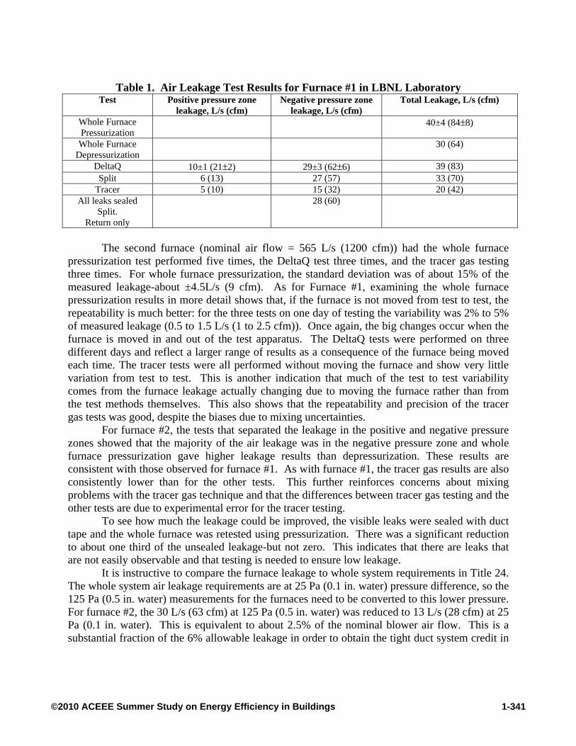
Table 1. Air Leakage Test Results for Furnace #1 in LBNL Laboratory Test Positive pressure zone
leakage, L/s (cfm) Negative pressure zone
leakage, L/s (cfm) Total Leakage, L/s (cfm)
Whole Furnace Pressurization
40±4 (84±8)
Whole Furnace Depressurization
30 (64)
DeltaQ 10±1 (21±2) 29±3 (62±6) 39 (83) Split 6 (13) 27 (57) 33 (70)
Tracer 5 (10) 15 (32) 20 (42) All leaks sealed
Split. Return only
28 (60)
The second furnace (nominal air flow = 565 L/s (1200 cfm)) had the whole furnace
pressurization test performed five times, the DeltaQ test three times, and the tracer gas testing three times. For whole furnace pressurization, the standard deviation was of about 15% of the measured leakage-about ±4.5L/s (9 cfm). As for Furnace #1, examining the whole furnace pressurization results in more detail shows that, if the furnace is not moved from test to test, the repeatability is much better: for the three tests on one day of testing the variability was 2% to 5% of measured leakage (0.5 to 1.5 L/s (1 to 2.5 cfm)). Once again, the big changes occur when the furnace is moved in and out of the test apparatus. The DeltaQ tests were performed on three different days and reflect a larger range of results as a consequence of the furnace being moved each time. The tracer tests were all performed without moving the furnace and show very little variation from test to test. This is another indication that much of the test to test variability comes from the furnace leakage actually changing due to moving the furnace rather than from the test methods themselves. This also shows that the repeatability and precision of the tracer gas tests was good, despite the biases due to mixing uncertainties.
For furnace #2, the tests that separated the leakage in the positive and negative pressure zones showed that the majority of the air leakage was in the negative pressure zone and whole furnace pressurization gave higher leakage results than depressurization. These results are consistent with those observed for furnace #1. As with furnace #1, the tracer gas results are also consistently lower than for the other tests. This further reinforces concerns about mixing problems with the tracer gas technique and that the differences between tracer gas testing and the other tests are due to experimental error for the tracer testing.
To see how much the leakage could be improved, the visible leaks were sealed with duct tape and the whole furnace was retested using pressurization. There was a significant reduction to about one third of the unsealed leakage-but not zero. This indicates that there are leaks that are not easily observable and that testing is needed to ensure low leakage.
It is instructive to compare the furnace leakage to whole system requirements in Title 24. The whole system air leakage requirements are at 25 Pa (0.1 in. water) pressure difference, so the 125 Pa (0.5 in. water) measurements for the furnaces need to be converted to this lower pressure. For furnace #2, the 30 L/s (63 cfm) at 125 Pa (0.5 in. water) was reduced to 13 L/s (28 cfm) at 25 Pa (0.1 in. water). This is equivalent to about 2.5% of the nominal blower air flow. This is a substantial fraction of the 6% allowable leakage in order to obtain the tight duct system credit in
1-341©2010 ACEEE Summer Study on Energy Efficiency in Buildings

Title 24. After sealing, the furnace only contributes about 1% of air leakage at 25 Pa (0.1 in. water).
Table 2. Air Leakage Test Results for Furnace #2 in LBNL Laboratory Test Positive pressure zone
leakage, L/s (cfm) Negative pressure zone
leakage, L/s (cfm) Total Leakage, L/s (cfm)
Whole Furnace Pressurization
30±4 (63±9)1
Whole Furnace Depressurization
25 (52)
DeltaQ 6 to 8 (13 to 18) 19 to 27 (41 to 58) 33 (70) 2 Fans 5 (11) 21 (45) 26 (56) Split 22 (47) 38 (80) 60 (127)
Tracer 3 to 5 (6 to 10) 11 to 12 (23 to 25) 15 (32) All leaks sealed Whole Furnace Pressurization
11 (23)
1- Same day test results with furnace not moved between tests: Day 1: 33±1.5 (69±2.5) and Day 2: 25±0.5 (54±1) The third furnace (nominal air flow = 470 L/s (1000 cfm)) had the whole furnace
pressurization test performed three times and the DeltaQ test three times. The whole furnace pressurization tests were done on two days with a 12 L/s (25 cfm) change from day 1 to day 2. The two tests on the second day are only different by 0.5 L/s (1 cfm). As with the other two furnaces, the big changes occur when the furnace is moved in and out of the test apparatus. The DeltaQ tests were performed on three different days and show a similar variability to the pressurization tests.
For furnace #3, the tests that separated the leakage in the positive and negative pressure zones showed that the majority of the air leakage was in the negative pressure zone. This is consistent with the other two furnaces. As with furnace #1 and #2, the tracer gas results are consistently lower than for the other tests although the repeatability is excellent-indicating that the test procedure has systematic bias (almost certainly due to insufficient mixing of tracer gas).
The RTU (capacity = 6 tons; nominal air flow = 1130 L/s (2400 cfm)) was only tested a single time and the pressurization test result was 11 L/s (23 cfm). This was the least leaky piece of heating/cooling equipment tested despite being by far the physically largest. Visual inspection showed that the cabinet was constructed better than the furnaces. It used gaskets on seams, particularly in the blower compartment door that had a foam rubber gasket seal that worked well even with a dent in the blower access panel.
Table 3. Air Leakage Test Results for Furnace #3 in LBNL Laboratory
Test Positive pressure zone leakage, L/s (cfm)
Negative pressure zone leakage, L/s (cfm)
Total Leakage, L/s (cfm)
Whole Furnace Pressurization
Day 1: 12 (25) and Day 2: 24 & 25 (51 & 52)
DeltaQ 4, 6, 6 (8,12,13) 17, 22, 29 (35,47,61) 28 (60) Tracer 3.5, 4 (7, 9) 14, 14 (30, 31) 18 (38)
1-342©2010 ACEEE Summer Study on Energy Efficiency in Buildings
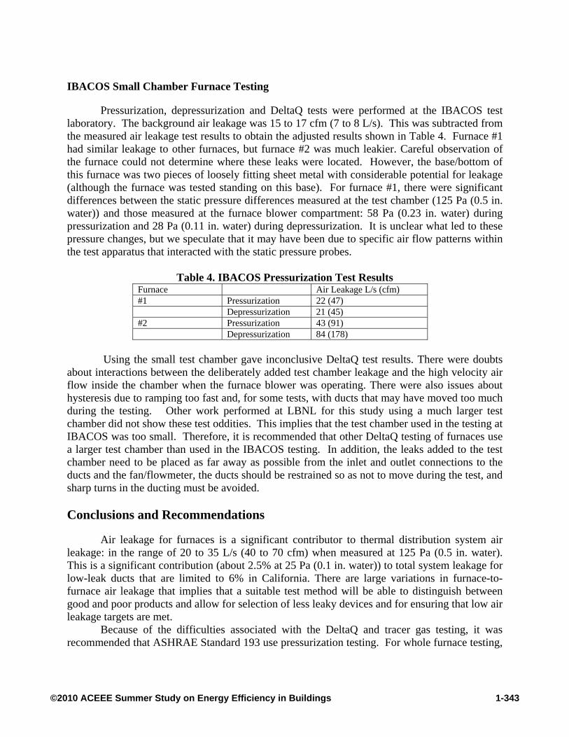
IBACOS Small Chamber Furnace Testing
Pressurization, depressurization and DeltaQ tests were performed at the IBACOS test laboratory. The background air leakage was 15 to 17 cfm (7 to 8 L/s). This was subtracted from the measured air leakage test results to obtain the adjusted results shown in Table 4. Furnace #1 had similar leakage to other furnaces, but furnace #2 was much leakier. Careful observation of the furnace could not determine where these leaks were located. However, the base/bottom of this furnace was two pieces of loosely fitting sheet metal with considerable potential for leakage (although the furnace was tested standing on this base). For furnace #1, there were significant differences between the static pressure differences measured at the test chamber (125 Pa (0.5 in. water)) and those measured at the furnace blower compartment: 58 Pa (0.23 in. water) during pressurization and 28 Pa (0.11 in. water) during depressurization. It is unclear what led to these pressure changes, but we speculate that it may have been due to specific air flow patterns within the test apparatus that interacted with the static pressure probes.
Table 4. IBACOS Pressurization Test Results
Furnace Air Leakage L/s (cfm) #1 Pressurization 22 (47) Depressurization 21 (45) #2 Pressurization 43 (91) Depressurization 84 (178)
Using the small test chamber gave inconclusive DeltaQ test results. There were doubts
about interactions between the deliberately added test chamber leakage and the high velocity air flow inside the chamber when the furnace blower was operating. There were also issues about hysteresis due to ramping too fast and, for some tests, with ducts that may have moved too much during the testing. Other work performed at LBNL for this study using a much larger test chamber did not show these test oddities. This implies that the test chamber used in the testing at IBACOS was too small. Therefore, it is recommended that other DeltaQ testing of furnaces use a larger test chamber than used in the IBACOS testing. In addition, the leaks added to the test chamber need to be placed as far away as possible from the inlet and outlet connections to the ducts and the fan/flowmeter, the ducts should be restrained so as not to move during the test, and sharp turns in the ducting must be avoided. Conclusions and Recommendations
Air leakage for furnaces is a significant contributor to thermal distribution system air leakage: in the range of 20 to 35 L/s (40 to 70 cfm) when measured at 125 Pa (0.5 in. water). This is a significant contribution (about 2.5% at 25 Pa (0.1 in. water)) to total system leakage for low-leak ducts that are limited to 6% in California. There are large variations in furnace-to-furnace air leakage that implies that a suitable test method will be able to distinguish between good and poor products and allow for selection of less leaky devices and for ensuring that low air leakage targets are met.
Because of the difficulties associated with the DeltaQ and tracer gas testing, it was recommended that ASHRAE Standard 193 use pressurization testing. For whole furnace testing,
1-343©2010 ACEEE Summer Study on Energy Efficiency in Buildings

the furnace should be depressurized because blower compartment leakage is generally greater than furnace outlet leakage and depressurizing puts the same direction of pressure difference across the dominant leaks. Alternatively, if the furnace is split into outlet and blower compartment sides internally, than the split test can be used. Repeatability of pressurization testing was 5 L/s (10 cfm), with most of the variability due to shifting of furnace panels when the furnace was moved. It is recommended that more furnaces be tested in the future with a particular focus on testing repeatability.
The test results from Standard 193 are at a fixed test pressure. For any individual installation, the actual system pressures can be higher or lower than the test pressures; therefore, adjustments should be made accordingly if accurate energy loss estimates are to be made (e.g., using ASHRAE Standard 152).
The use of better cabinet materials (e.g., thicker gauge steel) and seals on access panels could reduce furnace cabinet air leakage and may improve Standard 193 repeatability under different physical testing configurations.
References ASHRAE Standard 193 (2010). “Method of Test for Determining the Airtightness of HVAC
Equipment”. ASHRAE, Atlanta, GA.
ASHRAE Standard 62.2 (2007). “Ventilation and Acceptable Indoor Air Quality in Low-Rise Residential Buildings”. ASHRAE, Atlanta, GA.
ASHRAE Standard 152 (2007), Method of Test for Determining the Design and Seasonal Efficiencies of Residential Thermal Distribution Systems. ASHRAE . Atlanta, GA.
ASTM E1554-07 (2007). Standard Test Methods for Determining Air Leakage of Air Distribution Systems by Fan Pressurization. American Society for Testing and Materials. West Conshohocken, PA.
ASTM E283-04 (2004). Standard Test Method for Determining the rate of Air Leakage Through Exterior Windows, Curtain Walls and Doors under Specified Pressure Differences across the Specimen. American Society for Testing and Materials. West Conshohocken, PA.
ASTM E779-03 (2003), Standard Test Method for Determining Air Leakage by Fan Pressurization. American Society for Testing and Materials, West Conshohocken, PA.
CEC (2008a). Reference Appendixes for the 2008 Building Energy Efficiency Standards for Residential and NonResidential Buildings. CEC-400-2008-004-CMF. California Energy Commission, Sacramento, CA.
CEC (2008b). Residential Alternative Calculation Manual (ACM) Approval Method 2008 Building Energy Efficiency Standards. CEC-400-2008-002-CMF. California Energy Commission, Sacramento, CA.
1-344©2010 ACEEE Summer Study on Energy Efficiency in Buildings

Cummings, J., Withers, C., McIlvaine, J., Sonne, J. and Lombardi, M. 2003. “Air Handler leakage: Field Testing Results in Residences”. Florida Solar Energy Center Research Report: FSEC- RR – 138-03. FSEC, Florida.
Florida Building Code (2003). Florida Building Commission.
Walker, I., Sherman, M., Seigel, J., Wang, D., Buchanan, C., and Modera, M. 1998. “Leakage Diagnostics, Sealant Longevity, Sealant Longevity, Sizing and Technology Transfer in Residential Thermal Distribution Systems: Part II”. LBNL- 42691. Lawrence Berkeley National Laboratory, Berkeley, CA.
Walker, I.S., Sherman, M.H., Wempen, J., Wang, D., McWilliams, J.A., and Dickerhoff, D.J. 2001. Development of a New Duct Leakage Test: Delta Q. LBNL-47308.
Walker, I.S. and Dickerhoff, D.J. (2008). “Field and Laboratory Evaluation of a New Ramping Technique for Duct Leakage Testing”. ASHRAE Transactions, June 2008. ASHRAE, Atlanta, GA. LBNL 62262.
Walker, I.S., Dickerhoff, D.J. and Delp, W.W. (2010). "Residential Forced Air System Cabinet Leakage and Blower Performance", California Energy Commission Public Interest Energy Research Program, Sacramento, CA.
Wilcox et al. (2006). Presentation for 2008 Standard Workshop. http://www.energy.ca.gov/title24/2008standards/documents/2006-07-12_workshop/ presentations/2006-07-17_FAN_FLOW_WATT_DRAW.PDF
1-345©2010 ACEEE Summer Study on Energy Efficiency in Buildings