air gap control simulation of a magnetically levitated...
TRANSCRIPT

Air Gap Control Simulation of a Magnetically Levitated Train
Ki-Jung Kim1 , Hyung-Suk Han2, Seok-Jo Yang1
1 Mechatronice Engineering, Chungnam National University,
99 Daehak-Ro, Yuseng-Gu, Daejeon 305-764, Korea 2 Magnetic Levitation and Linear Drive, Korea Institute of Machinery and Materials
156 Gajeongbuk-Ro, Yuseong-Gu, Daejeon 305-343, Korea
Abstract. Air gap, clearance between guideway surface and supporting magnet, of a magnetic train should be maintained within a limited value for preventing physical contact. The levitation control unit consists of electromagnets, gap sensors, choppers, and a controller. Thus, it would be desirable to include all the mechanical and electrical parts in the air gap simulation model. This paper presents the much more detailed dynamic modeling techniques, considering all the components, to more realistically predict the air gaps of the magnetic train under consideration. With the proposed model, air gaps are simulated to evaluate whether the mechanical contact would be occurred at maximum design speed.
Keywords: We would like to encourage you to list your keywords in this section.
1 Introduction
The magnetically levitated trains, as shown in Figure 1, have been proposed as a new passenger transportation mode due to their environmental advantages over conventional wheel-on-rail ones. One of the means of levitation is the use of attractive force of electromagnets being actively controlled for supporting the train without contact. It is the core technology in this kind of train to maintain all the air gaps within a certain range, for instance 8mm, to prevent physical contact between vehicle and guideway surface by control levitation control method. The air gap variations depend heavily on various elements from guideway and vehicle. For example, the guideway’s structural characteristics, such as stiffness, mass, and surface irregularities, as well as vehicle’s mechanical and electrical. Therefore, to optimize the vehicle and guideway, it would be desirable to include all the components in air gap simulations. In the 1970s, some researchers extensively studied the evaluation of dynamic characteristics, like ride quality, of magnetic trains according to guideway construction tolerances and deflections [1-3]. Most dynamics model used was a planar model. To achieve a more realistic air gap, it would be desirable to include all the components in space with less simplification. The paper presents the much more detailed dynamic modeling techniques, considering all the components, to more
IST 2013, ASTL Vol. 23, pp. 293 - 298, 2013 © SERSC 2013
293
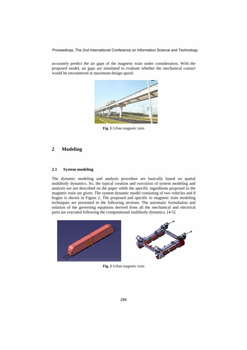
accurately predict the air gaps of the magnetic train under consideration. With the proposed model, air gaps are simulated to evaluate whether the mechanical contact would be encountered at maximum design speed.
Fig. 1 Urban magnetic train
2 Modeling
2.1 System modeling
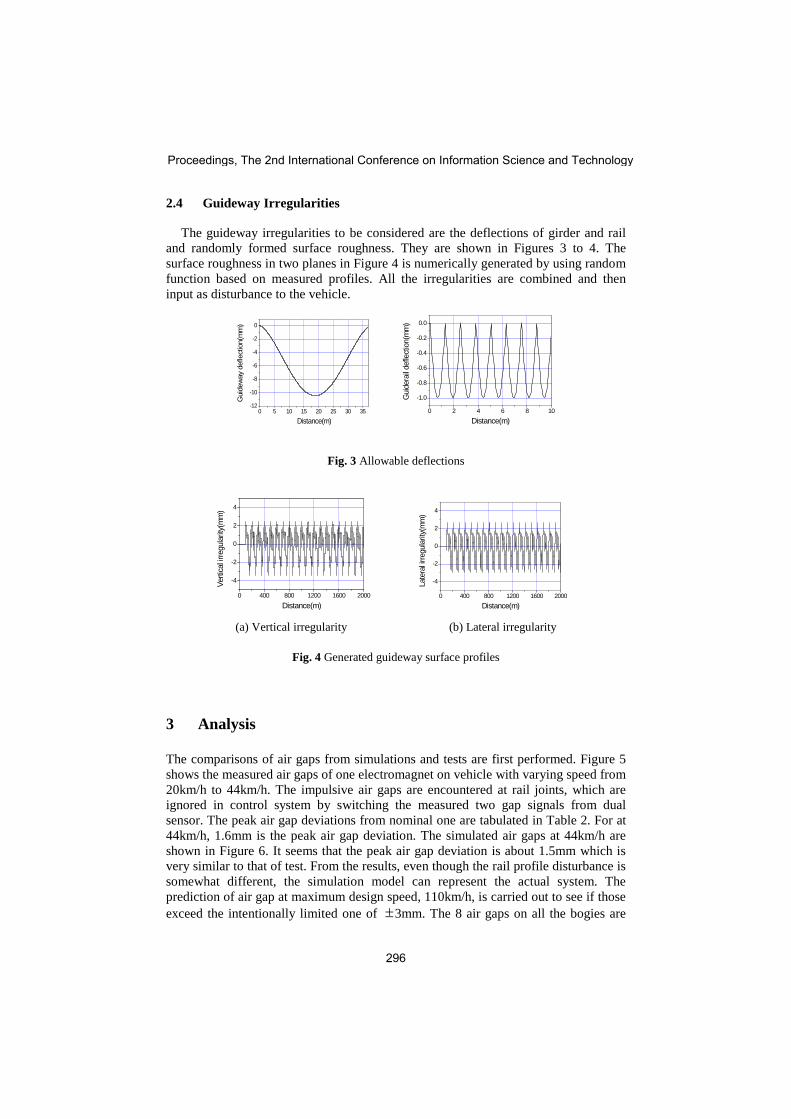
The dynamic modeling and analysis procedure are basically based on spatial multibody dynamics. So, the typical creation and execution of system modeling and analysis are not described on the paper while the specific ingredients proposed in the magnetic train are given. The system dynamic model consisting of two vehicles and 8 bogies is shown in Figure 2. The proposed and specific to magnetic train modeling techniques are presented in the following sections. The automatic formulation and solution of the governing equations derived from all the mechanical and electrical parts are executed following the computational multibody dynamics. [4-5]
Fig. 2 Urban magnetic train
Proceedings, The 2nd International Conference on Information Science and Technology
294

2.2 Electromagnet
The levitation force ( )zF t , or lift force, and guidance force ( )yF t are functions of the air gap, ( )c t , lateral displacement, ( )d t , and current ( )i t . To define both the forces, the idle levitation force 0F (t) is first defined when ( )d t 0= [2]. A reasonably accurate linear model may be obtained by using linear approximations of the idle levitation force around the nominal equilibrium point 0 0( , )i c :
0 c i staticF ( c( t ), i( t )) k c( t ) k i( t ) F∆ ∆ = ∆ − ∆ + (1)
c
i 0 0
k R 1i( t ) c( t ) i( t ) v( t )k L L
∆ ∆ ∆ ∆= − + (2)
where
20
00
N AL
2cµ
= , 2
0 0i 2
0
N Aik
2cµ
= , 2 2
0 0c 3
0
N Aik
2cµ
=
staticF : Static force (N), 0F : Idle levitation force (N), A : Section area of magnet (m2), 0µ : Permeability factor, N : Number of turn of magnet coil (turn), 0i : Nominal
current (A), 0c : Nominal air gap (m), c : Air gap (m), v : Voltage (V), R : Resistance (Ω ).
2.3 Levitation Control
The train employs the 5 states feedback control law to maintain the change in ( )c t∆ within an allowable magnitude [6]. Using the control law, the controlled voltage is determined by
1 2 3 4 5
ˆˆ ˆ ˆˆv( t ) k z( t ) k z( t ) k z( t ) k c( t ) k c( t )∆ = ∆ + ∆ + ∆ + ∆ + ∆ (5) where z( t )∆ : Observed acceleration, z( t )∆ : Observed velocity, z( t )∆ : Observed
position, c( t )∆ : Observed air gap velocity, c( t )∆ : Observed air gap, 1 2 3 4 5k , k , k , k , k : Control gains.
As it is practically difficult to measure all 5 states in the Equation (5), an observer for estimation of the 5 states using only two states, which are the acceleration of the electromagnet ( )z t∆ and the air gap ( )c t∆ , is used in the paper. Of course, the observer is designed in consideration of the operating speed and the guideway characteristics.
Air Gap Control Simulation of a Magnetically Levitated Train
295
2.4 Guideway Irregularities
The guideway irregularities to be considered are the deflections of girder and rail and randomly formed surface roughness. They are shown in Figures 3 to 4. The surface roughness in two planes in Figure 4 is numerically generated by using random function based on measured profiles. All the irregularities are combined and then input as disturbance to the vehicle.
0 5 10 15 20 25 30 35-12
-10
-8
-6
-4
-2
0
Gui
dew
ay d
efle
ctio
n(m
m)
Distance(m) 0 2 4 6 8 10
-1.0
-0.8
-0.6
-0.4
-0.2
0.0
Gui
dera
il def
lect
ion(
mm
)
Distance(m)
Fig. 3 Allowable deflections
0 400 800 1200 1600 2000
-4
-2
0
2
4
Verti
cal ir
regu
larit
y(m
m)
Distance(m) 0 400 800 1200 1600 2000
-4
-2
0
2
4
Late
ral ir
regu
larit
y(m
m)
Distance(m) (a) Vertical irregularity (b) Lateral irregularity
Fig. 4 Generated guideway surface profiles
3 Analysis
The comparisons of air gaps from simulations and tests are first performed. Figure 5 shows the measured air gaps of one electromagnet on vehicle with varying speed from 20km/h to 44km/h. The impulsive air gaps are encountered at rail joints, which are ignored in control system by switching the measured two gap signals from dual sensor. The peak air gap deviations from nominal one are tabulated in Table 2. For at 44km/h, 1.6mm is the peak air gap deviation. The simulated air gaps at 44km/h are shown in Figure 6. It seems that the peak air gap deviation is about 1.5mm which is very similar to that of test. From the results, even though the rail profile disturbance is somewhat different, the simulation model can represent the actual system. The prediction of air gap at maximum design speed, 110km/h, is carried out to see if those exceed the intentionally limited one of ±3mm. The 8 air gaps on all the bogies are
Proceedings, The 2nd International Conference on Information Science and Technology
296

simulated at the speed of 110km/h, as shown in Figure 7. Deviations of all the air gaps from the nominal one of 8mm are within ±3mm. Therefore, it can be expected that the magnetic train can run without mechanical contact between guideway surface and vehicle at 110km/h, maximum design speed.
Fig. 5 Variation air gap according to velocity
Table 2. Air gap deviations
Speed(km/h) 20 25 30 44 Air gap deviation(mm) 0.9 1.1 1.3 1.6
16 18 20 22 24 26 28 30
6.5
7.0
7.5
8.0
8.5
9.0
9.5
10.0
Verti
cal a
ir ga
p(m
m)
Distance(m)
Bogie1LF
Fig. 6 Vertical air gap at 44km/h
15 20 25 304
5
6
7
8
9
10
11
12
Verti
cal a
ir ga
p(m
m)
Time(sec)
Bogie1LF Bogie2LR Bogie3LF Bogie4LR
15 20 25 304
5
6
7
8
9
10
11
12
Verti
cal a
ir ga
p(m
m)
Time(sec)
Bogie5LF Bogie6LR Bogie7LF Bogie8LR
(a) Leading vehicle (b) Trailing vehicle
Fig. 7 Vertical air gaps at 110km/h
Air Gap Control Simulation of a Magnetically Levitated Train
297

4 Conclusion
It is confirmed that the proposed air gap simulation model including all the mechanical and electrical components well represents the actual magnetic train under consideration. With the model, peak variation of air gaps, at maximum speed of 110km/h, are predicted to see whether exceeds the allowed deviation, ±3mm. It can be noted that the resulting air gap deviations obtained by simulations are within ±3mm, which means the magnetic train could run without physical contact up to 110km/h. The model providing more realistic air gap simulation could be employed to optimize the magnetic train system.
References
1. Cai, Y. and Chen, S.S., A Review of Dynamic Characteristics of Magnetically Levitated Vehicle Systems, Argonne National Laboratory, Argonne, Illinois (1995)
2. Sinha, P.K., Electromagnetic Suspension Dynamics & Control, Peter Peregrinus Ltd., London, UK (1987)
3. Hedrick, J.K., Ravera, R.J. and Anderes, J.R., The Effect of Elevated Guideway Construction Tolerances on Vehicle Ride Quality, J. of Dynamic Systems, Measurement, and Control, pp.408-416 (1975)
4. H.S Han, J.M Lee, H.K Sung, B.H Kim, and K.J Kim "Dynamic Modeling of Magnetically Levitated Vehicle Running over a Flexible Guideway", Proceedings of Multibody dynamics2007, pp. 46-47 (2007)
5. Han, H.S., "A study on the dynamic modeling of a magnetic levitation vehicle," JSME International, Vol. 46, No. 4, pp. 1497~1501(2003)
6. Han, H.S., Yim, B.H., Lee, N.J., Kim, Y.J., and Kim, B.H., "Prediction of ride quality of a Maglev vehicle using a full vehicle multi-body dynamic model," Vehicle System Dynamics, Vol. 47, No. 10, pp. 1~16 (2009)
7. Yim, B. H. and Han, H. S., "Curve negotiation analysis of a Maglev vehicle utilizing electromagnetic suspension system," Vehicle System Dynamics, Vol. 47, No. 10, pp. 1287~1304 (2009)
Proceedings, The 2nd International Conference on Information Science and Technology
298