air filter apparatus with modularized self-cleaning filter system
TRANSCRIPT

.
UIlltGd States Patent [19] [11] Patent Number: 4,740,221 Howeth [45] Date of Patent: Apr. 26, 1988
[54] AIR FILTER APPARATUS WITH , Primary Examiner~Charles Hart MODULARIZED SELF-CLEANING FILTER ' Attorney, Agent, or Firm--—Hubbard, Thurman, Turner SYSTEM & Tucker
[76] Inventor: D. Franklin Howeth, 233 Chuck Wagon Trail, Fort Worth, Tex. [57] ABSTRACT 76103 Disclosed is an air ?lter apparatus having a separator
‘ chamber formed by a housing in which a barrier type [21] App!‘ No’: 936’823 ?lter element is mounted to an annular back?ushing air [22] Filed: Dec. 2, 1986 reservoir or manifold having a bore therethrough on a
4 unitary support member which may be removed from E5} :1:133131313111313:2:31:iiiiiiiiiii'ggy??‘l?l he hhhhhh hhhhhgh hhh hhhhhhh hhhh how
55/502; 55/508; 55/510; 55/513’ ?lter element flushing air discharge heads are mounted [58] Field of Search ............... .. 55/293, 294, 312, 493, t° the manimld and dislwsed We’ the ?lter element
55 /502’ 508, 510, 513 clean air discharge chambers and are movable away _ from the manifold bore so that the ?lter element may be
[56] References cued inserted into and removed from the separator chamber. U.S. PATENT DOCUMENTS The ?lter element support member is secured to the
3,360,910 l/1968 Soltis ............................... .. 55/502 X manifold by Pins which Support a ?ange for mwemem 3,513,633 5/1970 Young 55 /302 X relative to the housing to relieve pressure differentials 3,803,807 4/1974 Mills .... .. 55/293 X across the ?lter element to prevent rupture of the ele
llim‘r et a1 55225323 ment or minimize the hazard of failures elsewhere in the , , rey ............ ,. filter system_
4,218,277 8/1980 Van Der Bur .. 156/96 4,233,041 11/1980 Noland ....... 55/294 X 4,544,389 10/1985 Howeth .............................. .. 55/302 46 Claims, 6 Drawing Sheets

US. Patent Apr. 26, 1988 Sheet 1 of6 4,740,221 ’

4,740,221 ' US. Patent Apr. 26, 1988 Sheet 2 0f 6

US. Patent Apr. 26, 1988 Sheet 3 of6 4,740,221 I
\Gl éiiil-l

US. Patent Apr. 26, 1988 Sheet 4 of 6 4,740,221
2M) 2'4 Q4
@ IJ
FIG. 8 FIG. 9


US. Patent Apr. 26, 1988 Sheet 6 of6 4,740,221
325
FIG. 12

4,740,22 1 1
AIR FILTER APPARATUS WITH MODULARIZED SELF-CLEANING FILTER SYSTEM
BACKGROUND OF THE INVENTION
1. Field of the Invention The present invention pertains to an air ?lter unit
having a housing which is constructed to provide for insertion of and removal of a barrier or impingement air ?lter element from a top side of the housing and includ ing a plurality of reverse ?ow air cleaning nozzles
5
which are mounted on a manifold surrounding an open- . ing in the housing through which the ?lter element may be inserted and removed without removal of the mani fold or nozzle structure.
2. Description of the Prior Art The continued emphasis on reducing atmospheric
pollution caused by air-borne particulate material has placed further demands on the development of suitable impingement or barrier type air ?lter apparatus by way of reducing the physical size of the apparatus while maintaining a suitable material separation or cleaning function and without unduly stressing or shortening the life of the ?lter element structure.
In an effort to reduce the overall physical size of air ?lter apparatus for relatively large scale industrial appli cations of various types the multiple, cloth bag type ?lter units have, to some extent, been obsoleted by the development of ?lter units utilizing so-called pleated paper barrier or impingement type ?lters. This type of ?lter element has been used in relatively light duty applications such as ?ltering combustion air in internal combustion engines of various types where physical size of the ?lter is of some concern but particulate material loadings on the ?lter element are usually relatively light. The adaptation of pleated paper or similar types of
porous media ?lter elements to industrial type ?lter apparatus has been accomplished in one sense by the so-called derating of the ?lter element so that it can accommodate relatively high material loading rates and be adequately cleaned as well as withstand repeated reverse air jet type cleaning processes. Such an ap proach to the improvement of air ?lter apparatus is described in US. Pat. No. 4,218,227 to Robert E. Frey. One reason for the development of the derated pleated paper ?lter is to minimize pressure losses of the air ?owing across the ?lter element so that the pleated paper ?lter is competitive with the so called cloth bag type ?lters. ' -
Prior to the development of the invention in US. Pat. No. 4,544,389, the arrangement of mounting cylindrical pleated paper and similar barrier type ?lter elements within a ?lter housing was necessarily complicated by the structure of the air pressure pulse or shock wave type reverse air jet cleaning devices. This prior art type structure required that the ?lter element be removed from the sidewall or bottom wall of the ?lter housing and which thereby required entry into the ?lter housing from the so called “dirty” side of the ?lter unit. This type of arrangement is unattractive for several reasons including the disadvantage that service personnel are unavoidably contaminated with the particulate material being removed from the ?lter during servicing and handling of the ?lter element, the handling of the ?lter element is dif?cult, insertion of and removal of the ?lter element with respect to the housing is a cumbersome and dif?cult process and the physical size and construc
15
25
30
35
40
45
65
2 tion of the ?lter housing is complicated. It is desirable in most ?lter applications that the ?lter element be remov able from the top of its housing which advantageously can provide for access to the “clean” air side of the housing. This simpli?es ?lter unit construction and does not require that service personnel become unduly con taminated by the material being separated from the air flow stream being ?ltered.
SUMMARY OF THE INVENTION
The present invention provides an improved air ?lter apparatus including a barrier or porous media impinge ment type ?lter system that is adaptable to a variety of particulate preseparator housings. In accordance with one aspect of the invention a cylindrical barrier type ?lter element, particularly a pleated paper type element, is supported in a ?lter housing and is removable from a top wall of the housing without requiring the movement of a large portion of the ?lter structure and without requiring that service personnel be exposed to substan tial contamination by the particulate material separated from the air ?owing through the ?lter unit. The present invention also provides an air ?lter apparatus having a ?lter element which may be thoroughly cleaned by a reverse ?ow of flushing air without adversely stressing the filter element and without requiring that the ?lter element be substantially derated as regards its air ?ow capacity.
In accordance with another aspect of the present invention there is provided a ?lter apparatus having a mounting structure for a barrier type ?lter element which may be inserted through a top wall of a ?lter housing and which may be secured in the ?lter housing in such a way that only a single seal surface is required to be closed between the dirty or contaminated air side of the housing and the clean air or outlet side of the housing. Moreover, the ?lter housing and the structure for providing reverse ?ow ?lter element cleaning air are uniquely adapted to provide easy access to the ?lter element. , _
In accordance with another aspect of the present invention an air ?lter apparatus is provided having re verse ?ow ?lter element cleaning or flushing air struc ture including a flushing air manifold which is of suf? cient air storage capacity to provide for relatively large flow volumes of reverse flow flushing air and wherein a plurality of reverse flow ?ushing air nozzle heads are mounted in such a way that they may be easily moved aside to permit insertion of and removal of the barrier type ?lter element and its support structure. The ?lter element is conveniently mounted on a generally cylin drical support member which is provided with a tubular conduit for conducting clean air from the ?lter element during its normal operation and for conducting rela tively large volumes of reverse ?ow flushing air to remove particulate material from the ?lter element without generating the severe shock or vibratory type forces associated with conventional reverse flow air jet cleaning systems.
In yet a further aspect of the invention, there is pro vided a structurally and functionally independent mod ularized self-cleaning ?lter system that is adapted for use with a variety of particulate pre-separators. The module of the present invention combines the features of ?ltration and ?lter cleaning into an integrated unit that may be ?tted into known cabinetry to provide an improved system.

4,740,22 l 3
Still further advantages and features of the present invention include the provision of a ?lter element which may be passed through a relatively large bore formed in the ?lter housing, which bore is formed by a wall of a backflushing air manifold and which bore also provides for insertion of and removal of the barrier type ?lter element with respect to the ?lter chamber. For both so-called positive and negative pressure type applica tions the ?lter element support member is secured to the ?lter housing by a unique retaining structure which permits movement of the support member and the ?lter element to relieve any excessive pressure differentials between the separation chamber and the clean air ?ow chamber of the ?lter unit to minimize the chance of structural damage to the ?lter apparatus or the ?lter element. In that regard, the present invention may in clude ?lter pressure support members which prevent collapse of the filter element due to pressure differential across the ?lter medium. Although certain features and advantage of the pres
ent invention have been described hereinabove those skilled in the art will further appreciate these features as well as additional superior aspects of the invention upon reading the detailed description which follows.
BRIEF DESCRIPTION OF THE DRAWING
FIG. 1 is a side elevation of an air ?lter apparatus in accordance with the present invention; _ FIG. 2 is a vertical central section view of the ?lter
apparatus taken along Line 2-2 of FIG. 1; FIG. 3 is a section view taken generally along the line
3-3 of FIG. 2; _ FIG. 4 is a section view taken along the line 4-—4 of
FIG. 2; FIG. 5 is a detail section view showing the releasable
connection between on of the backflushing air dis charge heads and its supply manifold; FIG. 6 is a detail section view taken along line 6—6 of
FIG. 3, and showing one of the retaining members for . the barrier ?lter support member;
FIG. 7 is a view taken from the same line as the view of FIG. 3 and showing the backflushing air heads moved clear of the ?lter support member. FIG. 8 is a side view of an impact and gravity
preseparator housing showing the environment of a self-cleaning ?lter module of the present invention; FIG. 9 is a side view of a gravity preseparator hous
ing showing another environment of a self-cleaning ?lter module of the present invention; FIG. 10 is a vertical section view of one embodiment
of a self-cleaning ?lter module according to the present invention; FIG. 11 is an. end view of the module taken generally
along line 11-11 of FIG. 10; and, FIG. 12 is a vertical section view of another embodi
ment of a self-cleaning ?lter module according to the present invention.
DESCRIPTION OF THE PREFERRED EMBODIMENT
In the description which follows like parts are marked throughout the speci?cation and drawing with the same reference numerals, respectively. The drawing ?gures are not necessarily to scale and certain features of the invention may be shown exaggerated in scale or in somewhat schematic form in the interest of clarity.
Referring to FIG. 1, an air ?lter apparatus in accor dance with one embodiment of the present invention is
15
25
35
45
65
4 illustrated and generally designated by the numeral 10. The ?lter apparatus 10 includes a cyclonic inertial preseparator, which includes a generally cylindrical housing 12 having a depending frusto-conical material discharge hopper portion 14 which is provided with a suitable air lock type discharge valve 16 for discharging particulate material collected within the housing 12 into a suitable receiving bin or other receiving means, gener ally designated by the numeral 18. Referring also to FIG. 2, the ?lter housing 12 has a generally horizontal top wall 20 on which is mounted a clean air discharge conduit 22. The conduit 22 includes a support ?ange 24 which is hinged to the top wall 20 at 26 and is secured in a closed position over an opening 30 in the wall 20 by one or more suitable removable fasteners 28. The partic ular discharge conduit 22 illustrated is exemplary as will be appreciated by those skilled in the art and may be replaced by other structure having a support ?ange or a similar member for disposition over the relatively large diameter opening 30. The ?lter apparatus 10 may be adapted for a wide
variety of air ?ltering applications and may, for exam ple, be used in conjunction with collecting particulate matter entrained in a bailing air ?ow stream emanating from a drill hole during rock drilling or other earth drilling operations. In this respect the ?lter apparatus 10 may be suitably mounted by a bracket member 32, FIG. 1, on a frame 34 comprising part of a drilling rig or the like, otherwise not shown. The salient features of the ?lter apparatus 10, may be embodied in a variety of ?lter apparatus which may be structurally modi?ed in ways not affecting the invention for various speci?c air ?ltering applications. The housing 12 is further pro vided with a generally rectangular shaped air inlet con duit 36 secured to the housing 12 and opening to the interior thereof in a generally tangential manner with respect to the cylindrical con?guration of the housing 12 which is connected to a source, not shown, of air laden with particulate material. The ?lter apparatus 10 may be used in conjunction with so-called positive pres sure air conveying means wherein air is forced through a passage 37 formed by the conduit 36 into the interior of housing 12 at a pressure greater than the ambient atmospheric pressure, or the ?lter unit 10 may be incor porated in a system wherein a suction pump or the like is disposed to be in communication with the conduit 22 downstream of the apparatus 10 with respect to air flow therethrough and thereby maintain a pressure within the housing 12 generally less than ambient atmospheric pressure.
Referring primarily to FIG. 2, the housing 12 in cludes an upper section 13 including the top wall 20 and a cylindrical sidewall 21 which may extend to the inter section of the cylindrical portion of the housing 12 with the hopper portion 14 and whereby the housing 12 may comprise a unitary structure characterized by the top wall 20, the cylindrical sidewall portion 21 and the conical hopper portion 14. The illustrated embodiment of the housing 12 includes a lower cylindrical section 23 secured to the upper section 13 across cooperating ?anges 25 and 27 suitably secured together by fasteners 29. The top wall 20 may also be fabricated separate from the housing section 13 in order to facilitate certain machining operations for the section 13. The housing 12 further includes an interior transverse
partition or wall 38 and a second transverse partition or wall 40 which are delimited by and contiguous with a cylindrical wall portion 42 de?ning a bore 44 extending
4,740,221 5
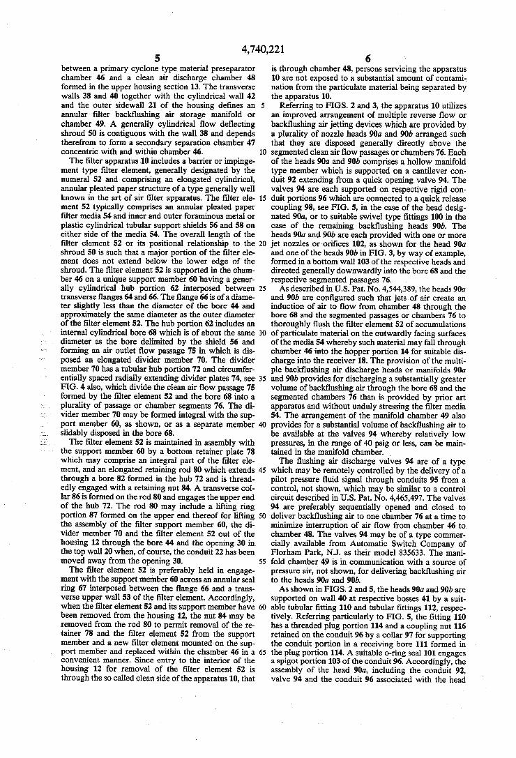
between a primary cyclone type material preseparator chamber 46 and a clean air discharge chamber 48 formed in the upper housing section 13. The transverse walls 38 and 40 together with the cylindrical wall 42 and the outer sidewall 21 of the housing de?nes an annular ?lter back?ushing air storage manifold or chamber 49. A generally cylindrical ?ow de?ecting shroud 50 is contiguous with the wall 38 and depends therefrom to form a secondary separation chamber 47 concentric with and within chamber 46. The ?lter apparatus 10 includes a barrier or impinge
ment type ?lter element, generally designated by the numeral 52 and comprising an elongated cylindrical, annular pleated paper structure of a type generally well known in the an of air ?lter apparatus. The ?lter ele ment 52 typically comprises an annular pleated paper ?lter media 54 and inner and outer foraminous metal or plastic cylindrical tubular support shields 56 and 58 on either side of the media 54. The overall length of the ?lter element 52 or its positional relationship to the shroud 50 is such that a major portion of the ?lter ele ment does not extend below the lower edge of the shroud. The ?lter element 52 is supported in the cham ber 46 on a unique support member 60 having a gener ally cylindrical hub portion 62 interposed between transverse ?anges 64 and 66. The ?ange 66 is of a diame ter slightly less than the diameter of the bore 44 and approximately the same diameter as the outer diameter of the ?lter element 52. The hub portion 62 includes an internal cylindrical bore 68 which is of about the same diameter as the bore delimited by the shield 56 and forming an air outlet ?ow passage 75 in which is dis posed an elongated divider member 70. The divider member 70 has a tubular hub portion 72 and circumfer entially spaced radially extending divider plates 74, see FIG. 4 also, which divide the clean air ?ow passage 75 formed by the ?lter element 52 and the bore 68 into a plurality of passage or chamber segments 76. The di vider member 70 may be formed integral with the sup port member 60, as shown, or as a separate member slidably disposed in the bore 68. The ?lter element 52 is maintained in assembly with
the support member 60 by a bottom retainer plate 78 which may comprise an integral part of the ?lter ele ment, and an elongated retaining rod 80 which extends through a bore 82 formed in the hub 72 and is thread edly engaged with a retaining nut 84. A transverse col lar 86 is formed on the rod 80 and engages the upper end of the hub 72. The rod 80 may include a lifting ring portion 87 formed on the upper end thereof for lifting the assembly of the ?lter support member 60, the di vider member 70 and the ?lter element 52 out of the housing 12 through the bore 44 and the opening 30 in the top wall 20 when, of course, the conduit 22 has been moved away from the opening 30. The ?lter element 52 is preferably held in engage
ment with the support member 60 across an annular seal ring 67 interposed between the ?ange 66 and a trans verse upper wall 53 of the ?lter element. Accordingly, when the ?lter element 52 and its support member have been removed from the housing 12, the nut 84 may be removed from the rod 80 to permit removal of the re tainer 78 and the ?lter element 52 from the support member and a new ?lter element mounted on the sup port member and replaced within the chamber 46 in a convenient manner. Since entry to the interior of the housing 12 for removal of the ?lter element 52 is through the so called clean side of the apparatus 10, that
5
10
20
25
35
45
55
65
6 ‘. is through chamber 48, persons servicing the apparatus 10 are not exposed to a substantial amount of contami nation from the particulate material being separated by the apparatus 10.
Referring to FIGS. 2 and 3, the apparatus 10 utilizes an improved arrangement of multiple reverse flow or back?ushing air jetting devices which are provided by a plurality of nozzle heads 90a and 90b arranged such that they are disposed generally directly above the segmented clean air ?ow passages or chambers 76. Each of the heads 90a and 90b comprises a hollow manifold type member which is supported on a cantilever con duit 92 extending from a quick opening valve 94. The valves 94 are each supported on respective rigid con duit portions 96 which are connected to a quick release coupling 98, see FIG. 5, in the case of the head desig nated 90a, or to suitable swivel type ?ttings 100 in the case of the remaining back?ushing heads 90b. The heads 90a and 90b are each provided with one or more jet nozzles or'ori?ces 102, as shown for the head 90a and one of the heads 90b in FIG. 3, by way of example, formed in a bottom wall 103 of the respective heads and directed generally downwardly into the bore 68 and the respective segmented passages 76. As described in US. Pat. No. 4,544,389, the heads 90a
and 90b are con?gured such that jetsof air create an induction of air to ?ow from chamber 48 through the bore 68 and the segmented passages or chambers 76 to thoroughly ?ush the ?lter element 52 of accumulations of particulate material on the outwardly facing surfaces of the media 54 whereby such material may fall through chamber 46 into the hopper portion 14 for suitable dis charge into the receiver 18. The provision of the multi ple back?ushing air discharge heads or manifolds 90a and 90b provides for discharging a substantially greater volume of back?ushing air through the bore 68 and the segmented chambers 76 than is provided by prior art apparatus and without unduly stressing the ?lter media 54. The arrangement of the manifold chamber 49 also provides for a substantial volume of back?ushing air to be available at the valves 94 whereby relatively low pressures, in the range of 40 psig or less, can be main tained in the manifold chamber. , The ?ushing air discharge valves 94 are of a type
which may be remotely controlled by the delivery of a pilot pressure ?uid signal through conduits 95 from a control, not shown, which may be similar to a control circuit described in US. Pat. No. 4,465,497. The valves 94 are preferably sequentially opened and closed to deliver back?ushing air to one chamber 76 at a time to minimize interruption of air ?ow from chamber 46 to chamber 48. The valves 94 may be of a type commer cially available from Automatic Switch Company of Florham Park, NJ. as their model 835633. The mani fold chamber 49 is in communication with a source of pressure air, not shown, for delivering back?ushing air to the heads 90a and 90b. As shown in FIGS. 2 and 5, the heads 90a and 90b are
supported on wall 40 at respective bosses 41 by a suit able tubular ?tting 110 and tubular ?ttings 112, respec tively. Referring particularly to FIG. 5, the ?tting 110 has a threaded plug portion 114 and a coupling nut 116 retained on the conduit 96 by a collar 97 for supporting the conduit portion in a receiving bore 111 formed in the plug portion 114. A suitable o-ring seal 101 engages a spigot portion 103 of the conduit 96. Accordingly, the assembly of the head 900, including the conduit 92, valve 94 and the conduit 96 associated with the head
4,740,221 7
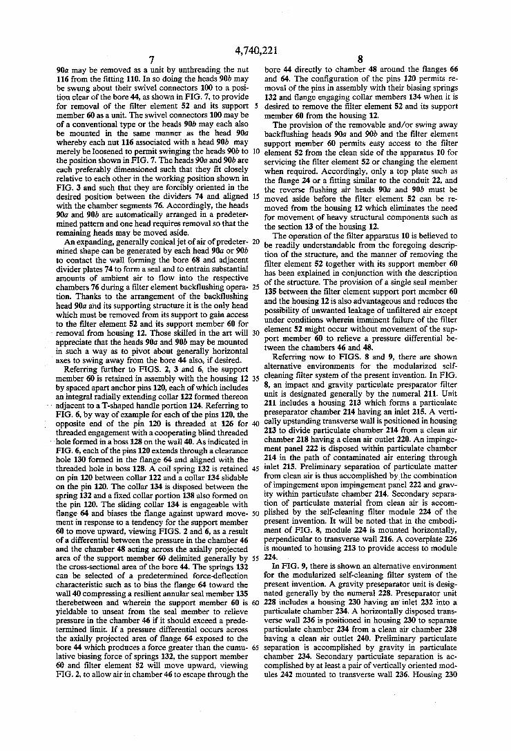
90a may be removed as a unit by unthreading the nut 116 from the ?tting 110. In so doing the heads 90b may be swung about their swivel connectors 100 to a posi tion clear of the bore 44, as shown in FIG. 7, to provide for removal of the ?lter element 52 and its support member 60 as a unit. The swivel connectors 100 may be of a conventional type or the heads 90b may each also be mounted in the same manner as the head 90a whereby each nut 116 associated with a head 90b may merely be loosened to permit swinging the heads 90b to the position shown in FIG. 7. The heads 90a and 90b are each preferably dimensioned such that they ?t closely relative to each other in the working position shown in FIG. 3 and such that they are forcibly oriented in the desired position between the dividers 74 and aligned with the chamber segments 76. Accordingly, the heads 90a and 90b are automatically arranged in a predeter mined pattern and one head requires removal so that the remaining heads may be moved aside. An expanding, generally conical jet of air of predeter
mined shape can be generated by each head 90a or 90b to contact the wall forming the bore 68 and adjacent divider plates 74 to form a seal and to entrain substantial amounts of ambient air to ?ow into the respective chambers 76 during a ?lter element back?ushing opera tion. Thanks to the arrangement of the back?ushing head 90a and its supporting structure it is the only head which must be removed from its support to gain access to the ?lter element 52 and its support member 60 for
' removal from housing 12. Those skilled in the art will appreciate that the heads 90a and 90b may be mounted in such a way as to pivot about generally horizontal
’ axes to swing away from the bore 44 also, if desired. Referring further to FIGS. 2, 3 and 6, the support
member 60 is retained in assembly with the housing 12 by spaced apart anchor pins 120, each of which includes an integral radially extending collar 122 formed thereon
~ adjacent to a T-shaped handle portion 124. Referring to FIG. 6, by way of example for each of the pins 120, the
‘ opposite end of the pin 120 is threaded at 126 for threaded engagement with a cooperating blind threaded
“ hole formed in a boss 128 on the wall 40. As indicated in FIG. 6, each of the pins 120 extends through a clearance hole 130 formed in the flange 64 and aligned with the threaded hole in boss 128. A coil spring 132 is retained on pin 120 between collar 122 and a collar 134 slidable on the pin 120. The collar 134 is disposed between the spring 132 and a ?xed collar portion 138 also formed on the pin 120. The sliding collar 134 is engageable with ?ange 64 and biases the ?ange against upward move ment in response to a tendency for the support member 60 to move upward, viewing FIGS. 2 and 6, as a result of a differential between the pressure in the chamber 46 and the chamber 48 acting across the axially projected area of the support member 60 delimited generally by the cross-sectional area of the bore 44. The springs 132 can be selected of a predetermined force-de?ection characteristic such as to bias the ?ange 64 toward the wall 40 compressing a resilient annular seal member 135 therebetween and wherein the support member 60 is yieldable to unseat from the seal member to relieve pressure in the chamber 46 if it should exceed a prede termined limit. If a pressure differential occurs across the axially projected area of ?ange 64 exposed to the‘ bore 44 which produces a force greater than the cumu lative biasing force of springs 132, the support member 60and ?lter element 52 will move upward, viewing FIG. 2, to allow air in chamber 46 to escape through the
10
15
20
25
35
40
45
65
8 bore 44 directly to chamber 48 around the ?anges 66 and 64. The con?guration of the pins 120 permits re moval of the pins in assembly with their biasing springs 132 and ?ange engaging collar members 134 when it is desired to remove the ?lter element 52 and its support member 60 from the housing 12. The provision of the removable and/or swing away
back?ushing heads 90a and 90b and the ?lter element support member 60 permits easy access to the ?lter element 52 from the clean side of the apparatus 10 for servicing the ?lter element 52 or changing the element when required. Accordingly, only a top plate ‘such as the ?ange 24 or a ?tting similar to the conduit 22, and the reverse ?ushing air heads 90a and 90b must be moved aside before the ?lter element 52 can be re moved from the housing 12 which eliminates the need for movement of heavy structural components such as the section 13 of the housing 12. The operation of the ?lter apparatus 10 is believed to
be readily understandable from the foregoing descrip tion of the structure, and the manner of removing the ?lter element 52 together with its support member 60 has been explained in conjunction with the description of the structure. The provision of a single seal member 135 between the ?lter element support port member 60 and the housing 12 is also advantageous and reduces the possibility of unwanted leakage of un?ltered air except under conditions wherein imminent failure of the ?lter element 52 might occur without movement of the sup port member 60 to relieve a pressure differential be tween the chambers 46 and 48.
Referring now to FIGS. 8 and 9, there are shown alternative environments for the modularized self cleaning ?lter system of the present invention. In FIG. 8, an impact and gravity particulate presparator ?lter unit is designated generally by the numeral 211. Unit 211 includes a housing 213 which forms a particulate preseparator chamber 214 having an inlet 215. A verti cally upstanding transverse wall is positioned in housing 213 to divide particulate chamber 214 from a clean air chamber 218 having a clean air outlet 220. An impinge ment panel 222 is disposed within particulate chamber 214 in the path of contaminated air entering through inlet 215. Preliminary separation of particulate matter from clean air is thus accomplished bythe combination of impingement upon impingement panel 222 and grav ity within particulate chamber 214. Secondary separa tion of particulate material from clean air is accom plished by the self-cleaning ?lter module 224 of the present invention. It will be noted that in the embodi ment of FIG. 8, module 224 is mounted horizontally, perpendicular to transverse wall 216. A coverplate 226 is mounted to housing 213 to provide access to module 224.
In FIG. 9, there is shown an alternative environment for the modularized self-cleaning ?lter system of the present invention. A gravity preseparator unit is desig nated generally by the numeral 228. Preseparator unit 228 includes a housing 230 having an‘ inlet 232 into a particulate chamber 234. A horizontally disposed trans verse wall 236 is positioned in housing 230 to separate particulate chamber 234 from a clean air chamber 238 having a clean air outlet 240. Preliminary particulate separation is accomplished by gravity in particulate chamber 234. Secondary particulate separation is ac complished by at least a pair of vertically oriented mod ules 242 mounted to transverse wall 236. Housing 230

4,740,221 9
includes coverplates 244 to provide access to module 242.
Referring now to FIGS. 10 and 11, which show the details of module 224 and its mounting to transverse wall 216 in the system of FIG. 8, transverse wall 216 includes a bore 246. Module 224 includes an annular manifold or pressure ?uid reservoir 248 which includes a transverse upstream wall 250 and a spaced apart trans verse downstream wall 252. A cylindrical wall 253 interconnects walls 250 and 252 to form a bore 255 through manifold 248. In the preferred embodiment of module 224, upstream wall 250 includes a contiguous radially outwardly extending mounting ?ange 254, which is mountable to transverse wall 216 by studs or the like. An annular seal ring or gasket 256 is disposed between mounting ?ange 254 and transverse wall 216. Module 224 includes an elongated cylindrical pleated
paper ?lter element 258. Filter element 258 is mounted to manifold 248 by a ?lter support member 259 which includes a cylindrical hub 260 including a ?rst ?ange 262 and an axially spaced apart second ?ange 264. A divider member 266 is supported by hub 260 and in cludes a central draw tube 268 having a plurality of the divider plates 270 extending radially therefrom. A plu rality of ?lter pressure support rings 272 are positioned axially along divider member 266 in order to provide pressure support to ?lter element 258.
Filter element 258 is mounted to hub 260 by means of a retention rod 274 disposed in draw tube 268. Reten tion rod 274 carries near one of its ends an end cap 276. The other end of retention rod 274 is threaded for en gagement with a rod eye 278. Rod eye 278 bears on the end of draw tube 268 and the threaded cooperation of rod eye 278 with retention rod 274 draws end cap 276 toward the end of ?lter 258, which in turn is drawn toward second ?ange 264. Seal rings 280 and 281 are disposed between the ends of ?lter element 258 and second ?ange 264 and end cap 276, respectively, to seal the bore of ?lter element 258 and hub 260.
Filter element 258 and hub 260 are mounted to mani fold 248 by means of spaced apart anchor pins con nected to manifold 248, which engage clearance holes in ?rst ?ange 262 in a manner similar to that described with respect to FIGS. 2, 3 and 6, above. Knobs 284 threadedly engage anchor pins 282 to retain springs 286, which bias ?rst ?ange 262 toward downstream wall 252 of manifold 248. A seal ring 288 is disposed between ?rst ?ange 262 and downstream wall 252. As described above, if a pressure differential occurs across the axially projected area of ?rst ?ange 262 produces a force greater than the cumulative biasing force of springs 286, ?lter element 258 and support member hub 260 will move left-ward, viewing FIG. 10, to allow air to vent past seal ring 288. Module 224 includes a further support structure
which includes a pair of closely spaced apart axially extending ?lter insertion support rails 290 and a diamet rically spaced apart axially extending V-shaped particu late diverter 292. Particulate diverter 292 is positioned closely adjacent the top surface of ?lter element 258 and overlies vertically upstanding divider plate 270. Partic ulate diverter 292 thus diverts or de?ects laterally mate rial dislodged from ?lter 258 during back?ushing to prevent such material from being redeposited on ?lter 258. '
Support rails 290 and particulate diverter 292 are connected together by a ?lter safety stop member 294. Filter safety stop member 294 includes a central hole
10
20
25
30
35
40
45
55
60
65
10 296 which engages an alignment probe 298 formed by the end of retention rod 274. Support rails 290 and particulate diverter 292 thus form a cage-like structure mounted to upstream wall 250 of manifold 248. Support rails 290 provide a guide when ?lter element 258 and support member 259 are inserted through the bore 255 of manifold 248 and support rails 290 and the coopera tion of alignment probe 298 with hole 296 in ?lter safety stop 294 provide support to the horizontally mounted ?lter element 258. Module 224 includes a reverse ?ow back?ushing
system as described above, including nozzle heads 300 movably mounted in the manner described with respect to FIGS. 3, 5 and 7, above. Nozzle heads 300 are thus swingable out of the way so that ?lter element 258 and support member 260 may be inserted into and removed from the bore of manifold 248. Module 224 also includes a ?ushing event sequencer, which preferrably is of the type described in US Pat. No. 4,465,497, the disclosure of which is incorporated herein by reference. Module 224 thus provides a complete self-contained self-clean ing ?lter that may be installed as a unit in existing cabi netry.
Referring now to FIG. 12, there is shown in detail an alternative module 242 which includes a vertically aligned nonsegmented bore ?lter element 304. Module 242 is similar to module 224 and includes an annular manifold 306 sealingly mounted to the transverse wall 236 of the housing. A ?lter support member is mounted to manifold 306 in the manner described above and includes a draw tube 310 mounted to the hub of ?lter support member 308 by a support web 312. At least two ?lter pressure support rings 314 are mounted by webs at axially spaced apart locations on draw tube 310 to pro vide pressure support to ?lter element 304. A retention rod 316, including and end cap 318 and an alignment probe 320, is carried by draw tube 310 and is retained by threaded rod eye 322. A ?lter safety stop 324 is sup ported by diametrically spaced apart mounting bars 326 connected to manifold 306. Filter safety stop 324 en gages alignment probe 320 and prevents ?lter element 242 from falling into the separator cabinet if rod eye 232 becomes unscrewed. Module 242 includes a single multiple jet back?ush
ing head 326 and ?ushing sequencer 328, similar to those described above. Module 242 thus provides a self-contained self-cleaning ?lter system that may be installed as a unit in existing separator cabinetry. Although a preferred embodiment of the invention
has been described herein in detail, those skilled in the art will appreciate that various substitutions and modi? cations may be made to the invention. For example, it is! not necessary that the ?lter element 52 and its support member 60 be utilized in conjunction with a cyclone type separator to enjoy the advantages of a top loading, easily removed and insertable ?lter element structure. Forexample, the conduit 36 may enter the chamber 46 at other than a tangential direction to create the cy clonic ?ow. Moreover, the housing 12 may be modi?ed to be formed as part of a material discharge bin or re ceiving tank for pneumatic conveying systems and the like as opposed to being formed as a separate separating and ?ltering structure. What is claimed is: 1. Apparatus for separating particulate material from
an air ?ow stream, which comprises: a housing;

4,740,221 11
a back?ushing air storage manifold positioned in said housing, said manifold including a transverse downstream wall forming a material separation chamber in said housing, a transverse upstream wall spaced apart from said downstream wall, and a wall connecting said upstream and downstream walls and forming a bore through said manifold into said separation chamber; ,
inlet conduit means for conducting air laden with particulate material into said separation chamber;
a ?lter support member supported by said down stream wall of said manifold;
and a barrier type ?lter element supported by said ?lter support member in such a way that said ?lter element is insertable into and removable from said separation chamber through said bore.
2. The apparatus set forth in claim 1 including: a resilient seal member interposed between said sup
port member and said downstream wall of said manifold and forming a seal between said separa tion chamber and a clean air chamber formed in said housing.
3. The apparatus set forth in claim 1 including: a top wall of said housing spaced from said down
stream wall and de?ning a clean air ?ow chamber in said housing;
and back?ushing air head means supported in said housing and in ?ow receiving communication with said manifold for delivering ?lter element back ?ushing air to said ?lter element.
4. The apparatus set forth in claim 3 wherein: said back?ushing air head means includes a plurality
of back?ushing heads mounted on said manifold by means operable in such a way that said heads may be disposed in alignment with said bore in a ?rst position and are movable to a second position clear of said bore to provide for insertion and removal of said ?lter element through said bore.
5. The apparatus set forth in claim 4 wherein: at least one of said back?ushing heads includes a
releasable coupling for removing said head from said housing.
6. The apparatus set forth in claim 3 wherein: said support member includes a ?rst flange adapted to be supported on said downstream wall, and resil ient seal means interposed between said down stream wall and said ?rst ?ange and forming a seal between said separation chamber and said clean air chamber. -
7. The apparatus set forth in claim 6 including: means dividing at least a portion of said ?lter element
into plural chamber segments aligned with said head means for conducting a ?ow of back?ushing air through at least a portion of said ?lter element to dislodge particulate material accumulated thereon. ‘
8. The apparatus set forth in claim 6, wherein: said support member includes a second ?ange formed
thereon and spaced from said ?rst ?ange and means interconnecting said ?rst and second ?anges and forming a flow passage therebetween, said second ?ange being operable to support said ?lter element at one end of said ?lter element.
9. The apparatus set forth in claim 6 including: means for yieldably biasing said ?rst ?ange toward
said downstream wall. 10. The apparatus set forth in claim 9 wherein:
15
25
30
35
40
50
55
65
12 said ?rst ?ange includes a plurality of clearance holes formed therein spaced apart one from the other, and said means for yieldably biasing said ?rst ?ange includes a plurality of retaining pins extend ing through said clearance holes and releasably connected to said downstream wall, said retaining pins each including spring means disposed thereon and operable to bias said ?rst ?ange toward said downstream wall.
11. The apparatus set forth in claim 10 wherein: said retaining pins include means for securing said
springs on said pins when said pins are discon nected from said downstream wall.
12. The apparatus as claimed in claim 1, including: back?ushing air head means supported by said down
stream wall for delivering back?ushing air to said ?lter element.
13. The apparatus as claimed in claim 12, wherein: said back?ushing air head means includes a back
?ushing head movably mounted to said down stream wall and movable between a ?rst position in alignment with said bore to deliver back?ushing air to said ?lter element and a second position clear of said bore so that said ?lter element may be inserted into and removed from said separation chamber through said bore.
14. The apparatus as claimed in claim 13, wherein said flushing head includes:
a ?rst conduit conduit connected to said downstream wall;
a second conduit extending generally perpendicular to said ?rst conduit;
means for pivotally interconnecting said ?rst and second conduits;
and a nozzle head connected to said second conduit. 15. Apparatus for separating particulate material
from an air ?ow stream comprising: a housing forming a material separation chamber; inlet conduit means in communication with said hous
ing for conducting air laden with particulate mate rial into said separation chamber;
a transverse wall of said housing, defining part of said separation chamber;
means forming a bore opening through said trans verse wall into said housing and of suf?cient diame ter to permit insertion and removal of a barrier type ?lter element with respect to said separation cham ber;
a top wall of said housing spaced from said transverse wall and de?ning a clean air flow chamber in said housing;
a back?ushing air storage manifold formed in said housing between an outer side wall of said housing and said bore, and back?ushing air head means supported in said housing and in ?ow receiving communication with said manifold for delivering ?lter element back?ushing air through said pas sage;
a barrier type ?lter element, said ?lter element de?n ing at least an in part clean air ?ow passage means for conducting clean air in said apparatus; and
a ?lter support member for supporting said ?lter element in said separation chamber, said support member including a portion for supporting said support member and said ?lter element in said housing in such a way that said support member and said ?lter element are insertable in and remov able from said bore and with respect to said trans

4,740,221 13
verse wall, said support member including a ?rst ?ange adapted to be supported on said transverse wall, resilient seal means interposed between said transverse wall and said ?rst ?ange and forming a seal between said separtion chamber and said clean 5 air chamber, and means contiguous with said ?rst ?ange and de?ning part of said passage, and said ?rst ?ange including a plurality of clearance holes formed therein spaced apart one from the other, and means for yieldably biasing said ?rst ?ange 10 toward said transverse wall including a plurality of retaining pins extending through said clearance holes and releasably connected to said transverse wall, said retaining pins each including spring means disposed thereon and operable to bias said 15_ ?rst ?ange toward said transverse wall.
16. Apparatus for separating particulate material from an air ?ow stream comprising:
a housing forming a material separation chamber and a clean air chamber;
inlet conduit means in communication with said hous ing for conducting air laden with particulate mate rial into said separation chamber;
a transverse wall of said housing, de?ning part of said separation chamber and interposed between said material separation chamber and said clean air chamber;
means forming a bore opening through said trans verse wall in said housing and of suf?cient diameter to permit insertion and removal of a barrier type ?lter element with respect to said material separa tion chamber;
a barrier type ?lter element, said ?lter element de?n ing at least in part clean air ?ow passage means for 35 conducting clean air in said apparatus;
- ?lter support means, removably connectable to said transverse wall, for supporting said ?lter element in said material separation chamber in a manner such that said ?lter support means and said ?lter element 40 are insertable in and removable from said bore;
resilient seal means, interposed between said trans verse wall and a portion of said ?lter support means, for forming a seal between said material separation chamber and said clean air chamber; and 45
safety venting attachment means for removably con necting a portion of said ?lter support means to said transverse wall in a manner maintaining the
14 an annular back?ushing air manifold positioned in
said housing adjacent said transverse wall, said manifold including a wall forming a bore through said manifold in alignment with said bore of said transverse wall; ,
and a barrier type ?lter element supported by said transverse wall in such a way that said ?lter ele ment is insertable into and removable from said separation chamber through said bores of said transverse wall and manifold.
18. The apparatus as claimed in claim 17, including: a ?lter support member supported by said transverse
wall and supporting said ?lter element, said ?lter support member being removable with said ?lter element through said clean air chamber;
and means for sealing between said ?lter support member and said transverse wall.
19. The apparatus as claimed in claim 18, including spring means urging said ?lter support member toward said transverse wall.
20. The apparatus as claimed in claim 17, including back?ushing air head means supported in said clean air chamber for discharging back?ushing air from said manifold to back?ush said ?lter element, said back?ush ing air head means being movable between a ?rst posi tion in alignment with said bores of said transverse wall and manifold to discharge back?ushing air into said ?lter element and a second position out of alignment
30 with said bores of said transverse wall and manifold to allow removal of said ?lter element.
21. The apparatus as claimed in claim 20, wherein said transverse wall forms a wall of said manifold.
22. A self-cleaning ?lter module for use with a partic ulate pre'separator including a housing with a trans verse wall dividing said housing into a material separa tion chamber and a clean air chamber, said transverse wall having a bore therethrough connecting said clean air chamber with said material separation chamber, said self-cleaning ?lter module comprising:
an annular back?ushing air manifold sealingly mount able to said transverse wall of said particulate pre separator housing to further separate said clean air chamber from said material separation chamber, said manifold including a wall forming a bore through said manifold, said bore through said man ifold being aligned with said bore through said transverse wall when said manifold is mounted to
20
seal formed by said seal means during periods in said transverse wall; which the pressure differential between said mate- 5() and a barrier type ?lter element supported by said rial separation chamber and said clean air chamber manifold in such a way that said ?lter element is is below a predetermined level, and permitting insertable into and removable from said separation pressure-caused movement of said portion of said chamber through said bores of said transverse wall ?lter support means relative to said transverse wall, and manifold when said manifold is mounted to to ventingly communicate said material separation 55 said transverse wall. chamber and said clean air chamber across said seal 23. The self-cleaning ?lter module as claimed in claim means, during periods when the pressure differen- 22, including: tial between said material separation chamber and a ?lter support member supported by said manifold said clean air chamber is at or above said predeter- and supporting said ?lter element, said ?lter sup mined level. 60 port element being removable with said ?lter ele
17. Apparatus for separating particulate material from an air ?ow stream, which comprises:
a housing; a transverse wall positioned to divide said housing
into a clean air chamber and a material separation chamber, said transverse wall having a bore there through connecting said clean air chamber with said separation chamber;
ment through said clean air chamber; and means for sealing between said ?lter support member and said manifold.
24. The self-cleaning ?lter module as claimed in claim 65 22, including:
back?ushing air head means supported by said mani fold for delivering ?lter element back?ushing air to said ?lter element. '

4, 740,22 1 15
25. The self-cleaning ?lter module as claimed in claim 24, wherein:
said back?ushing air head means includes at least one back?ushing head mounted on said manifold by means operable in such a way that said head may be disposed in alignment with said bore of said mani fold to discharge back?ushing air into said bore and movable out of alignment with said bore of said manifold to provide for insertion and removal of said ?lter element through said bore of said mani fold.
26. The self-cleaning ?lter module as claimed in claim 22, wherein said manifold includes:
a transverse downstream wall; and a transverse upstream wall spaced apart from downstream wall, with said wall forming said bore of said manifold interconnecting said upstream and downstream walls of said manifold.
27. The self-cleaning ?lter module as claimed in claim 26, wherein said upstream wall of said manifold is seal ingly mountable to said transverse wall of said housing.
28. The self-cleaning ?lter module as claimed in claim 26, including: '
a ?lter support member supported by said down stream wall of said manifold and supporting said ?lter element;
and means for sealing between said ?lter support member and said downstream wall of said mani fold.
29. The self-cleaning ?lter module as claimed in claim 28, wherein said ?lter support member includes:
a ?rst ?ange supported on said downstream wall of said manifold and resilient seal means interposed between said downstream wall and said ?rst ?ange.
30. The self-cleaning ?lter module as claimed in claim 29, including: means for yieldably biasing said ?rst ?ange into en gagement with said downstream wall.
31. The self-cleaning ?lter module as claimed in claim 30, wherein:
said ?rst ?ange includes a plurality of clearance holes formed therein spaced apart from each other, and said means for yieldably biasing said ?rst ?ange includes a plurality of retaining pins extending through said clearance holes and releasably con nected to said downstream wall.
32. The self-cleaning ?lter module as claimed in claim 31, wherein:
said yieldably biasing means includes spring means disposed about said retaining pins for urging said ?rst ?ange toward said downstream wall.
33. The self-cleaning ?lter module as claimed in claim 22, including:
pressure support means for supporting said ?lter ele ment.
34. The self-cleaning ?lter module as claimed in claim 33, wherein said pressure support means includes:
a plurality of axially spaced apart support rings posi tioned in said ?lter element.
35. The self-cleaning ?lter module as claimed in claim 34, including:
divider means supporting said support rings and di viding the interior of said ?lter element into a plu rality of axially extending segments.
36. The self-cleaning ?lter module as claimed in claim 35, including:
5
15
25
30
35
50
65
16 a plurality of back?ushing heads mounted to said
manifold to discharge back?ushing air into said segments.
37. The self~cleaning ?lter module as claimed in claim 22 including: cage means connected to said manifold for supporting
said ?lter element. 38. The self-cleaning ?lter module as claimed in claim
37, wherein said ?lter module is adapted mounting with said ?lter element extending horizontally.
39. The self-cleaning ?lter module as claimed in claim 38, wherein said cage means includes:
a pair of axially extending substantially parallel sup port rails connected to said manifold and spaced apart from each other a distance less than the diam eter of said ?lter element to engage and support said ?lter element.
40. The self-cleaning ?lter module as claimed in claim 38, wherein said cage means includes:
diverter means connected to said manifold and ex tending axially along said ?lter element for divert ing laterally material dislodged from said ?lter element.
41. The self-cleaning ?lter module as claimed in claim 37, wherein said cage means includes:
a ?lter safety stop supported by said manifold to limit axial travel of said ?lter element with respect to said manifold.
42. The self-cleaning ?lter module as claimed in claim 41 including:
a ?lter support member supported by said manifold, said ?lter support member including alignment probe means engageable with said ?lter safety stop for aligning said ?lter element in said cage means.
43. The self-cleaning ?lter module as claimed in claim 36, including diverter means disposed exterior of said ?lter element for preventing material dislodged from said filter element during back?ushing from being rede posited on said ?lter element.
44. The self-cleaning ?lter module as claimed in claim 22, including:
a ?lter support member supported by said manifold and supporting said ?lter, said ?lter support mem ber including a retention rod having an end cap for engaging an end of said ?lter element.
45. The self-cleaning ?lter module as claimed in claim 44, including ?lter safety stop means supported by said manifold and wherein said retention rod includes an alignment probe engageable with said safety stop means to align said ?lter element with said bore of said mani fold.
46. The apparatus of claim 16 wherein: said portion of said ?lter support means comprises an
annular ?ange adapted to overlie said transverse wall,
said seal means comprise an annular seal member underlying said annular ?ange, and
said safety venting attachment means include a plu rality of circumferentially spaced threaded anchor pin members having enlarged stop portions thereon, said anchor pin members extending axially through said ?ange and permitting its movement along their lengths, a plurality of boss members each anchored to said transverse wall and thread ingly receiving an end portion of one of said an chor pin members, a plurality of collar members each carried by one of said anchor pin members for sliding movement along its length and bearing
4,740,22 1 17
against said transverse wall, and a plurality of com pression springs each coaxially circumscribing one of said anchor pin members and bearing at its oppo site ends against the stop portion and collar mem ber associated with such anchor pin member to thereby resilient urge its collar into contact with said ?ange, whereby said compression springs cre ate a resilient compressive force on said annular
15
20
25
30
35
45
50
55
65
18 seal member which may be selectively and evenly adjusted by appropriately loosening or tightening said anchor pin members in their associated boss members, and permit pressure-caused movement of said ?ange to ventingly communicate said material separation chamber and said clean air chamber across said annular seal member.
# i * ‘I it