air-cooled screw chillers 140 - 1710 kw presentations_fx-g05.pdfthe graph shows the chiller...
TRANSCRIPT

CHILLERSCOMFORT
Air-cooled screw chillers
140 - 1710 kW

2
Family overview
Technical insight
Controls and user interface
Versions
Operating limits
Heat recovery configurations
Low GWP refrigerant
Hydronic modules and flow controls
Coils & coatings
Further options
Screw Compressor
Air-cooled ChillerFX-G05

3
Family overview
Technical insight
Controls and user interface
Versions
Operating limits
Heat recovery configurations
Low GWP refrigerant
Hydronic modules and flow controls
Coils & coatings
Further options
Screw Compressor
Air-cooled ChillerFX-G05

4
FX-G05 - Family overview
Key features
Extensive
expertise
Powerful
adaptability
Low GWP
refrigerant
Chillers with low GWP refrigerant,
from 140 to 1710 kW

5
0 200 400 600 800 1000 1200 1400 1600 1800 2000
FX-G05 - Family overview
Cooling capacity range
Cooling capacity [kW]
FX-G05 1502 - 72232-3 compr. range
FX-G05 0751 - 1801Single compr. range
from 140 to 1710 kWLow GWP

6
4802/SL-E/RFX
FX-G05 - Family overview
Nomenclature
-G05
/K - Key efficiency
/CA - High efficiency
/E - Very high efficiency
/SL-K - Super low noise, key efficiency
/SL-CA - Super low noise, high efficiency
/SL-E - Super low noise, very high efficiency
- - Standard unit
/D - Partial heat recovery
/R - Total heat recovery
-G05 - R513A refrigerant
First three digits:
Nominal motor power of the compressors (HP)
Last digit:
Number of compressors
FX - Air cooled chiller with screw compressors
Version
Configuration
Family
Size
Refrigerant

7
Family overview
Technical insight
Controls and user interface
Versions
Operating limits
Heat recovery configurations
Low GWP refrigerant
Hydronic modules and flow controls
Coils & coatings
Further options
Screw Compressor
Air-cooled ChillerFX-G05

8
FX-G05 - Technical insight
The structure
One independent refrigerant circuit
per compressor, to grant reliability
and easy maintenance.
V-block structure with base and frame
in hot-galvanized steel sheet, all
parts polyester-painted.
Factory-installed pumps and pre-plumbed hydraulic components for the minimum on-site
installation time, work and cost (optional).
Large electrical panel
with general door lock
isolator, power circuit
components and
control main board.

9
FX-G05 - Technical insight
The CSC compressor
Innovative lubrication system
A devoted oil management valve calibrates
the oil circulation, for better performance.
Extreme durability
The carbon steel bearings are granted for
a lifetime of 150.000 hours.
Enhanced internal geometry
Internal volumes optimized for partial
loads bring excellent seasonal efficiency.
+1,6%
+8,5%
+11,7%
+15,5%
2,50
3,00
3,50
4,00
4,50
5,00
5,50
0 25 50 75 100
EE
Rg
ross [-]
Cooling load [%]
Part load efficiency
FX /CA 3602 FOCS2 /CA 3602
The graph shows the chiller efficiency with the variation of the load rate and air temperature (ESEER operating conditions).
Dual rotor screw compressor, designed according to
Mitsubishi Electric Hydronics & IT Cooling Systems
specifications and for its exclusive use.
Chiller with CSC screw compressor
Chiller with traditional screw compressor

10
0
100
200
300
400
500
600
700
800
900
1000
0
2.000
4.000
6.000
8.000
10.000
12.000
14.000
16.000
18.000
20.000
-10 -5 0 5 10 15 20 25 30 35
Coolin
g load [
kW
]
Energ
y absorb
ed [
kW
h/y
ear]
Outdoor temperature [°C]
FX-G05 - Technical insight
Energy analysis
Chiller with CSC screw compressor
London - FX-G05 /CA 3602Office building (Mon-Fri 06:00-20:00, Sat 06:00-14:00)
Chiller with traditional screw compr.
0
100
200
300
400
500
600
700
800
900
1000
0,00
2,00
4,00
6,00
8,00
10,00
12,00
Coolin
g load [
kW
]
EE
R [
-]
Outdoor temperature [°C]
Building cooling load
BIN profile

11
0
100
200
300
400
500
600
700
800
900
1000
0
2.000
4.000
6.000
8.000
10.000
12.000
14.000
16.000
18.000
20.000
-10 -5 0 5 10 15 20 25 30 35
Coolin
g load [
kW
]
Energ
y absorb
ed [
kW
h/y
ear]
Outdoor temperature [°C]
FX-G05 - Technical insight
Energy analysis
Chiller with CSC screw compressor
London - FX-G05 /CA 3602Office building (Mon-Fri 06:00-20:00, Sat 06:00-14:00)
Chiller with traditional screw compr.
0
100
200
300
400
500
600
700
800
900
1000
0,00
2,50
5,00
7,50
10,00
12,50
Coolin
g load [
kW
]
EE
R [
-]
Outdoor temperature [°C]
FX-G05 /CA 3602
Traditional screw chiller
Building cooling load
BIN profile

12
0
100
200
300
400
500
600
700
800
900
1000
0
2.000
4.000
6.000
8.000
10.000
12.000
14.000
16.000
18.000
20.000
-10 -5 0 5 10 15 20 25 30 35
Coolin
g load [
kW
]
Energ
y absorb
ed [
kW
h/y
ear]
Outdoor temperature [°C]
FX-G05 - Technical insight
Energy analysis
FX-G05 /CA 3602
Traditional screw chiller
Building cooling load
BIN profile
Chiller with CSC screw compressor
London - FX-G05 /CA 3602Office building (Mon-Fri 06:00-20:00, Sat 06:00-14:00)
Chiller with traditional screw compr.

13
0
100
200
300
400
500
600
700
800
900
1000
0
2.000
4.000
6.000
8.000
10.000
12.000
14.000
16.000
18.000
20.000
-10 -5 0 5 10 15 20 25 30 35
Coolin
g load [
kW
]
Energ
y absorb
ed [
kW
h/y
ear]
Outdoor temperature [°C]
FX-G05 - Technical insight
Energy analysis
FX-G05 /CA 3602
Traditional screw chiller
Building cooling load
BIN profile
Chiller with CSC screw compressor
London - FX-G05 /CA 3602Office building (Mon-Fri 06:00-20:00, Sat 06:00-14:00)
Chiller with traditional screw compr.
-10% Yearly energy
consumption
304 MWh/yTraditional screw chiller
274 MWh/yCSC screw chiller
14
FX-G05 - Technical insight
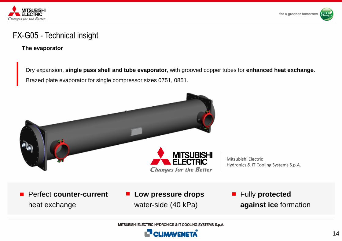
The evaporator
Dry expansion, single pass shell and tube evaporator, with grooved copper tubes for enhanced heat exchange.
Brazed plate evaporator for single compressor sizes 0751, 0851.
Fully protected
against ice formation
Low pressure drops
water-side (40 kPa)
Perfect counter-current
heat exchange
Mitsubishi ElectricHydronics & IT Cooling Systems S.p.A.

15
FX-G05 - Technical insight
The condenser
New generation full aluminum microchannel
coils, ideally positioned on a “V” block
structure to optimize airflow and heat transfer.
High performing axial fans equipped with
auto-transformer for speed adjustment.
Long Life Alloy (LLA) for
higher corrosion resistance
and longer life expectancy.
Traditional coils and
protective coating available
for harsh environments (Opt.)
Cut of energy
consumption and
noise emissions,
especially at part loads.
Up to 30% of
refrigerant charge
reduction Vs. traditional
tube and fin coils.
16
Family overview
Technical insight
Controls and user interface
Versions
Operating limits
Heat recovery configurations
Low GWP refrigerant
Hydronic modules and flow controls
Coils & coatings
Further options
Screw Compressor
Air-cooled ChillerFX-G05

17
FX-G05 - Controls and user interface
Control software
W3000TE: reliable and efficient operation is ensured
The logic behind FX-G05 is the W3000TE management software.
Characterized by advanced functions and algorithms, W3000TE features proprietary settings that ensure faster adaptive responses to
different dynamics, in all operating conditions.
Proprietary logicsAll the functions and algorithms are
developed in-house.
Security3 levels of password: user, service, manufacturer.
Connectivity• BMS: Modbus, LonWorks, BACnet MS/TP, BACnet-over-IP
• Proprietary devices: ClimaPRO, Manager3000
DiagnosticsAlarm acknowledgement, event records,
data download, black box function.
MonitoringEasy and complete visualization of the operation status.
User-friendly navigation tree.
ThermoregulationBased on dynamic dead band with a
DIP modulating adjustment.

18
FX-G05 - Controls and user interface
User interface
Direct control over the unit comes through the innovative KIPlink interface.
Based on the Wi-Fi technology, KIPlink gets rid of the standard keyboard and allows one to operate on the unit directly from his mobile
device (smartphone, tablet, notebook).
KIPlink: the Keyboard is In your Pocket

19
FX-G05 - Controls and user interface
User interface
Real-time graphs and trends
• Monitor the immediate labor status of
the compressors, heat exchangers,
cooling circuits and pumps.
• View the real-time graphs of the key
operating variable trends.
Easier on-site operation
• Monitor each component while moving
around the unit for maintenance.
• View and change all parameters with
easy-to-understand screenshots and
dedicated tooltips.
• Get devoted “help” message for alarm
reset and trouble shooting.
Data logger function
• View history of events and use the filter
for a simple search.
• Enhance diagnostics with data and
graphs of 10 minutes before and after
each alarm.
• Download all the data for detailed
analysis.
KIPlink: the Keyboard is In your Pocket

20
FX-G05 - Controls and user interface
User interface
Communication based on
Wi-Fi technology
(no internet connection needed)
An exclusive product of
Mitsubishi Electric Hydronics
& IT Cooling Systems S.p.A.
Hardware
Industrial characteristics, tolerates
temperatures from -20 to +65°C
Software compatibility with:IOS 8.0 and up
Android 5.0 and up
Chrome Web browser on Windows PC
A new approach to the Human Machine Interface

21
FX-G05 - Controls and user interface
User interface
Large
keyboard
7” touch
screen
In addition (Opt. 1442, 1444) or in
substitution (Opt. 6194, 6195) to the KIPlink:Options
LED
switch *
• Power LED
• Unit status LED
• On/off switch
KIPlink
hardware
• In the electrical
board
• Wi-Fi antenna
QR
code
• Scan to
have
access
* Provided when the unit is equipped with the KIPlink and without optional keyboard.
Standard equipment
Remote keyboards are available (Opt. C9261063, C9261064, C926108911, C926108913).

22
FX-G05 - Controls and user interface
Multi-unit system control
ClimaPRO: turn your plant room into a value generating asset
The ultimate plant room optimization solution.
According to the units' actual efficiency curves, ClimaPRO continuously optimizes plant working conditions by promptly adjusting
equipment staging and sequencing, managing operating set-points and controlling water flows throughout the entire system.
ClimaPRO can be interfaced with any BMS or perform all functions on its own.

23
Family overview
Technical insight
Controls and user interface
Versions
Operating limits
Heat recovery configurations
Low GWP refrigerant
Hydronic modules and flow controls
Coils & coatings
Further options
Screw Compressor
Air-cooled ChillerFX-G05

24
FX-G05 - Versions
Efficiency versions
3 levels of efficiency
EVery high
efficiency
CAHigh
efficiency
KKey
efficiency
* Regulation (EU) N.2281/2016
FX-G05 1502 - 72232-3 cpr: 289 - 1710 kW
EER: 3,16
EER: 3,03
EER: 2,74
SEER*: 4,32
SEER*: 4,22
SEER*: 4,10
Average values (EN14511)

25
FX-G05 - Versions
Efficiency versions
3 levels of efficiency
EVery high
efficiency
CAHigh
efficiency
KKey
efficiency
* Regulation (EU) N.2281/2016
N / A
N / A
EER: 2,81
N / A
N / A
FX-G05 0751 - 18011 cpr: 140 - 396 kW
SEER*: 3,89
Average values (EN14511)

26
FX-G05 - Versions
Acoustic versions
-Standard • Fans 900 rpm
Compressor acoustical
enclosure (Opt. 2301)
• Fans 900 rpm
• Compressor enclosure
Noise reducer kit
(Opt. 2315)
• Fans 840 rpm
• Compressor enclosure
SL Super low noise• Fans 775 rpm
• Special compressor enclosure
• Oversized condenser-12 dB(A)
-7 dB(A)
-2 dB(A)
Baseline
4 acoustic versions

27
Family overview
Technical insight
Controls and user interface
Versions
Operating limits
Heat recovery configurations
Low GWP refrigerant
Hydronic modules and flow controls
Coils & coatings
Further options
Screw Compressor
Air-cooled ChillerFX-G05

28
-30
-20
-10
0
10
20
30
40
50
60
-10 -5 0 5 10 15 20
Air te
mp
era
ture
(°C
)
Leaving water temperature (°C)
FX-G05 - Operating limits
Operating limits
Full load operating limits(Versions /E, /SL-E)*
Partial load operating limits In case of higher outdoor air temperature, the unit automatically
partializes its resources to ensure uninterrupted operation.
Operating limits when working partialized (water */7°C):
/K , /SL-K 53°C /CA , /SL-CA 55°C
/E , /SL-E 55°C +kit HT (all versions) 57°C
LWT < 0°C Compressor liquid injection (Opt. 871)
Air temp. < -10°C Double insulation on heat exchangers (Opt. 2631)
Standard unit
Required: EC fans (Opt. 808)
Required: EC fans (Opt. 808)
Low temp. device DBA (Opt. 813)
Required: Kit HT (Opt. 1955)
* For versions /K, /SL-K, the max outdoor temperature is lowered by 4°C
For versions /CA, /SL-CA, the max outdoor temperature is lowered by 2°C

29
Family overview
Technical insight
Controls and user interface
Versions
Operating limits
Heat recovery configurations
Low GWP refrigerant
Hydronic modules and flow controls
Coils & coatings
Further options
Screw Compressor
Air-cooled ChillerFX-G05

30
<
Standard Partial heat recovery Total heat recovery
FX-G05 - Heat recovery configurations
Overview
Heat recovery configurations provide heating for free.
Suitable for DHW production, integration of a boiler, air treatment in AHU.

31
FX-G05 - Heat recovery configurations
Standard
Pre
ssu
re
Enthalpy
No heat recovery
Standard refrigerant circuits.
All the condensation heat is dispersed in the air.
Standard

32
Pre
ssu
re
Enthalpy
FX-G05 - Heat recovery configurations
Partial heat recovery: /D
Each refrigerant circuit is fitted with a
desuperheater in series with the condenser coils.
20%of the chiller’s
capacity (*)
60°Cof leaving water
temperature
(*) The heat recovery and its amount depend on the unit’s operating conditions,
in particular the outdoor air temperature and the load percentage.
Approximately Up to
Partial heat recovery

33
FX-G05 - Heat recovery configurations
Partial heat recovery: /D
The desuperheater can recover the heat only when the temperature of the hot water circuit is lower than the compressor
discharge temperature.
It is advised to interrupt the water flow to the desuperheater when the conditions for an actual heat recovery are not met.
Heat recovery: ON Heat recovery: OFF water flow stopped

34
FX-G05 - Heat recovery configurations
Partial heat recovery: /D
Option 3371 D - RELAY 1 PUMP (ON/OFF) interrupts the water flow to the desuperheater when the conditions for
an actual heat recovery are not met.

35
Pre
ssu
re
Enthalpy
FX-G05 - Heat recovery configurations
Total heat recovery: /R
Each refrigerant circuit is fitted with a total heat recovery
exchanger, in parallel with the condenser coils.
100% of the chiller’s
capacity
60°Cof leaving water
temperature (*)
(*) Only for unit with option kit HT.
The maximum LWT for standard units is 55°C
Always Up to
Total heat recovery

36
FX-G05 - Heat recovery configurations
Total heat recovery: /R
The heat recovery mode is managed according to the hot water temperature set-point.
With the optional hydronic modules 4802 and 4803, the unit is provided with 1 or 2 relays to control the activation of 1 or
2 external pumps. The function “sniffer” is available.
Heat recovery: ON Heat recovery: OFF

37
Family overview
Technical insight
Controls and user interface
Versions
Operating limits
Heat recovery configurations
Low GWP refrigerant
Hydronic modules and flow controls
Coils & coatings
Further options
Screw Compressor
Air-cooled ChillerFX-G05

38
FX-G05 - Low GWP refrigerant
All-round approach to sustainability
Delivering brilliant annual efficiency is
fundamental, but is not enough.
New regulations like the EU F-gas and the
Kigali Amendment to the Montreal Protocol are
driving the industry towards new low GWP
refrigerants.
Today, an extended approach is the only way to effectively
reduce the Total Equivalent Warming Impact (TEWI).All-round sustainability

39
FX-G05 - Low GWP refrigerant
Possible alternatives
* IPCC AR4 ** ASHRAE 34; ISO 817
Unfortunately, the majority of low GWP refrigerants raises a critical
issue: flammability.Flammability

40
Flammability
FX-G05 - Low GWP refrigerant
Possible alternatives
The new refrigerant R513A, chosen for FX-G05, is a brilliant exception. FX-G05
* IPCC AR4 ** ASHRAE 34; ISO 817
41
FX-G05 - Low GWP refrigerant
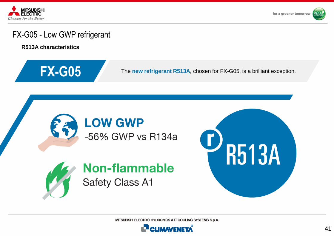
R513A characteristics
The new refrigerant R513A, chosen for FX-G05, is a brilliant exception. FX-G05

42
FX-G05 - Low GWP refrigerant
R513A characteristics
▪ Low GWP
R513A GWP100 year = 631
R134a GWP100 year = 1430
* GWP values according to IPCC AR4
New generation refrigerant: reduced greenhouse effect, nom-flammable.
▪ Non flammable
ASHRAE 34, ISO 817
Safety Class A1
(non toxic, non flammable)
PED (UNI EN 10204)
Fluid Group 2
(non dangerous)
▪ No special equipment
▪ No need for flammable
risk assessment
▪ No extra costs
In line with standard building codes
▪ No future retrofit required
▪ Reduced price volatility vs
high GWP refrigerants
Compliant with eco-regulation objectives
▪ Same cooling capacity
delivered as R134a
▪ Same operating pressures
as R134a
Favorable physical properties

43
Family overview
Technical insight
Controls and user interface
Versions
Operating limits
Heat recovery configurations
Low GWP refrigerant
Hydronic modules and flow controls
Coils & coatings
Further options
Screw Compressor
Air-cooled ChillerFX-G05

44
FX-G05 - Hydronic modules and flow controls
Option arrangement
Fixed speed pumps1 pump LH 2-poles: Opt. 4706
HH 2-poles: Opt. 4707
2 pumps LH 2-poles: Opt. 4711 / 4-poles: Opt. 4708
HH 2-poles: Opt. 4712 / 4-poles: Opt. 4709
Variable speed pumps1 pump LH 2-poles: Opt. 4717
HH 2-poles: Opt. 4718
2 pumps LH 2-poles: Opt. 4722 / 4-poles: Opt. 4719
HH 2-poles: Opt. 4723 / 4-poles: Opt. 4721
2 pumps (duty/standby) provide low or high head (available head approx. 100 or 200 kPa).
1 pump available for 1 cpr sizes.Factory-mounted
pump group
Terminals for
external pump
controlON/OFF signal1 pump Opt. 4702
2 pumps Opt. 4703
Modulating signal1 pump Opt. 4713
2 pumps Opt. 4714
The unit controls the activation or the activation and speed of 1 or 2 external pumps.
Hydronic modulesFX-G05 units can be equipped with a factory-mounted complete pump group or
simply with terminals to control the external pumps with the unit control logic.Hydronic modules

45
FX-G05 - Hydronic modules and flow controls
Option arrangement
The unit is set-up to operate with a constant water flow in the evaporator.
The unit can operate with both constant or variable flow.
Hydronic modulesDepending on the hydronic module selected, different flow controls are available
and managed by the unit’s control.Primary flow controls
Constant flowOpt. 4861
Flow controls available for:
Fixed speed pumps
or ON/OFF signal
Flow controls available for:
Variable speed pumps
or modulating signalVPF: constant ∆P
For systems with only the primary
circuit.
Opt. 4864 or 4865 for single unit system
Opt. 4866 for multi-unit system
VPF.D: constant ∆T
For systems with primary and
secondary circuits separated by a
hydraulic decoupler.
Opt. 4867 for single unit system
Opt. 4868 for multi-unit system
Constant flow
(parameter set)
For a quick and easy
commissioning.
Opt. 4862
Variable flowConstant flow
Sniffer function: When there is no request for cooling production, the primary pumps (built-in or external) are switched off and activated periodically only to let the unit
read the water temperature and sense the cooling request inception. Compatible with both constant and variable flow control.

46
FX-G05 - Hydronic modules and flow controls
Variable primary flow
The VPF control series (Variable Primary Flow) doesn’t only adjust the pump speeds on the basis of the
plant’s thermal load, but also dynamically optimizes the unit’s thermoregulation for variable flow
operation, thus ensuring both the highest pump energy savings and chiller stable operation.
Systems with only the primary circuit. Systems with primary and secondary circuits separated by a hydraulic decoupler.
VPF.D: constant ∆TVPF: constant ∆P
With the VPF system, the water flow can be reduced to 50% of the unit nominal water flow, with regards to the selection conditions, provided that the minimum water flow required by the unit’s heat exchanger is respected.

47
FX-G05 - Hydronic modules and flow controls
Pump group composition
The factory-mounted components of the pump groups are:
• Single-stage, close-coupled pumps by Grundfos.
• SiC/SiC (silicon carbide) primary seal pairing, extremely
resistant against wear, abrasive particles and wear.
• EPDM bellows seal prevent the risk of deposits, such as
rust, on the shaft.
• Pull-out design: during maintenance the power head can
be pulled out without removing the pump housing from the
pipework.
In-line pumps End-suction pumps
• Pumps*1 or 2 pumps, 2 or 4 poles, low or high head,
fix speed or variable speed (inverter)
• Pump enclosureAcoustically insulated for silenced units
• Suction and discharge valves
• One-way valve (in case of 2 pumps)
Flap type for in-line pumps
• Purge valve
• Drain plug
* In-line or end-suction models were chosen based on dimensions
and performances.
Excluded from the pump group supply, but mandatory
for the correct unit and system operation:
• Unit inlet water filter **with a maximum mesh size of 1 mm
• Unit outlet flow-switch **
** Available as accessories, supplied loose.

48
FX-G05 - Hydronic modules and flow controls
Pump group composition
Hydraulic diagram for 2 in-line pumps
Hydraulic diagram for 2 end-suction pumps
The factory-mounted components of the pump groups are:
• Pumps*1 or 2 pumps, 2 or 4 poles, low or high head,
fix speed or variable speed (inverter)
• Pump enclosureAcoustically insulated for silenced units
• Suction and discharge valves
• One-way valve (in case of 2 pumps)
Flap type for in-line pumps
• Purge valve
• Drain plug
* In-line or end-suction models were chosen based on dimensions
and performances.
Excluded from the pump group supply, but mandatory
for the correct unit and system operation:
• Unit inlet water filter **with a maximum mesh size of 1 mm
• Unit outlet flow-switch **
** Available as accessories, supplied loose.

49
Constant primary + variable secondary (primary circuit only)
FX-G05 - Hydronic modules and flow controls
VPF Vs. traditional solution
The same unit is installed in two different plants.
The pump regulation and the hydraulic scheme make the difference.
Fixed
speed
pump

50
Constant primary + variable secondary (primary circuit only)
FX-G05 - Hydronic modules and flow controls
VPF Vs. traditional solution
Fixed
speed
pump
FX-G05 /CA 3602CC: 838 kW
EER: 3,22
ESEER: 4,39
FX-G05 /CA 3602CC: 838 kW
EER: 3,22
ESEER: 4,39
NB 80-160/147Flow Q: 144 m3/h
Head Hu: 118 kPa
Power: 10,7 kW
NB 80-160/161+ inverterFlow Q: 144 m3/h
Head Hu: 228 kPa
Power: 18,8 kW
2x NBE 65-125/127Flow Q: 72 m3/h
Head Hu: 141 kPa
Power: 4,3 kW
The same unit is installed in two different plants.
The pump regulation and the hydraulic scheme make the difference.

51
0
100
200
300
400
500
600
700
800
900
1000
0
2.000
4.000
6.000
8.000
10.000
12.000
14.000
16.000
18.000
20.000
-10 -5 0 5 10 15 20 25 30 35
Coolin
g load [
kW
]
Energ
y absorb
ed [
kW
h/y
]
Outdoor temperature [°C]
FX-G05 - Hydronic modules and flow controls
VPF Vs. traditional solution
London - FX-G05 /CA 3602Office building (Mon-Fri 06:00-20:00, Sat 06:00-14:00)
Building cooling load
BIN profile
(primary circuit only)Constant primary + variable secondary

52
0
100
200
300
400
500
600
700
800
900
1000
0
2.000
4.000
6.000
8.000
10.000
12.000
14.000
16.000
18.000
20.000
-10 -5 0 5 10 15 20 25 30 35
Coolin
g load [
kW
]
Energ
y absorb
ed [
kW
h/y
]
Outdoor temperature [°C]
FX-G05 - Hydronic modules and flow controls
VPF Vs. traditional solution
London - FX-G05 /CA 3602Office building (Mon-Fri 06:00-20:00, Sat 06:00-14:00)
Const. prim. + var. sec.
VPF (only primary)
Building cooling load
BIN profile
(primary circuit only)Constant primary + variable secondary

53
0
100
200
300
400
500
600
700
800
900
1000
0
2.000
4.000
6.000
8.000
10.000
12.000
14.000
16.000
18.000
20.000
-10 -5 0 5 10 15 20 25 30 35
Coolin
g load [
kW
]
Energ
y absorb
ed [
kW
h/y
]
Outdoor temperature [°C]
FX-G05 - Hydronic modules and flow controls
VPF Vs. traditional solution
London - FX-G05 /CA 3602Office building (Mon-Fri 06:00-20:00, Sat 06:00-14:00)
Const. prim. + var. sec.
VPF (only primary)
Building cooling load
BIN profile
(primary circuit only)Constant primary + variable secondary
332,6 MWh/yConstant primary + variable secondary
279,1 MWh/yVPF (only primary)

54
0
100
200
300
400
500
600
700
800
900
1000
0
2.000
4.000
6.000
8.000
10.000
12.000
14.000
16.000
18.000
20.000
-10 -5 0 5 10 15 20 25 30 35
Coolin
g load [
kW
]
Energ
y absorb
ed [
kW
h/y
]
Outdoor temperature [°C]
FX-G05 - Hydronic modules and flow controls
VPF Vs. traditional solution
London - FX-G05 /CA 3602Office building (Mon-Fri 06:00-20:00, Sat 06:00-14:00)
Const. prim. + var. sec.
VPF (only primary)
Building cooling load
BIN profile
(primary circuit only)Constant primary + variable secondary
-17% Yearly energy
consumption
332,6 MWh/yConstant primary + variable secondary
279,1 MWh/yVPF (only primary)

55
Family overview
Technical insight
Controls and user interface
Versions
Operating limits
Heat recovery configurations
Low GWP refrigerant
Hydronic modules and flow controls
Coils & coatings
Further options
Screw Compressor
Air-cooled ChillerFX-G05

56
FX-G05 - Coils & coatings
The environments
Urban
environment
Rural
environment
Industrial
environment
Marine and
coastal
environment
Different environments need for different solutions

57
FX-G05 - Coils & coatings
Technologies and treatments
TUBE & FIN COILS
Cu/Al - Pre-painted fins (Opt. 894)
Cu/Al - Spray coating (Opt. 895 / RFQ)
Cu/Al - Regular (Opt. 879)
Cu/Cu - Tube & fin coil (Opt. 881)
MICROCHANNEL COILS
Al - Regular (std)
Al - E-coating (Opt. 876)

58
FX-G05 - Coils & coatings
Technologies and treatments
MICROCHANNEL COILS
Al - Regular (std)
Al - E-coating (Opt. 876)
TUBE & FIN COILS
Cu/Al - Pre-painted fins (Opt. 894)
Cu/Al - Spray coating (Opt. 895 / RFQ)
Cu/Al - Regular (Opt. 879)
Cu/Cu - Tube & fin coil (Opt. 881)

59
FX-G05 - Coils & coatings
Technologies and treatments
TUBE & FIN COILS
Cu/Al - Pre-painted fins (Opt. 894)
Cu/Al - Spray coating (Opt. 895 / RFQ)
Cu/Al - Regular (Opt. 879)
Cu/Cu - Tube & fin coil (Opt. 881)
MICROCHANNEL COILS
Al - Regular (std)
Al - E-coating (Opt. 876)
E-coated MCHE
Alkaline cleaning
Deionized water rinse
E-coat treatment
Final rinse
Ovenbake
UV topcoat
E-coating process
3120 hSWAAT test(ASTM G85-02 A3)
✓ UV rays

60
FX-G05 - Coils & coatings
Technologies and treatments
TUBE & FIN COILS
Cu/Al - Pre-painted fins (Opt. 894)
Cu/Al - Spray coating (Opt. 895 / RFQ)
Cu/Al - Regular (Opt. 879)
Cu/Cu - Tube & fin coil (Opt. 881)
MICROCHANNEL COILS
Al - Regular (std)
Al - E-coating (Opt. 876)

61
FX-G05 - Coils & coatings
Technologies and treatments
TUBE & FIN COILS
Cu/Al - Pre-painted fins (Opt. 894)
Cu/Al - Spray coating (Opt. 895 / RFQ)
Cu/Al - Regular (Opt. 879)
Cu/Cu - Tube & fin coil (Opt. 881)
Polyurethane resin
✓ 3000 h ASTM B117
✓ UV rays
Opt. 895
Polyurethane resin
✓ 4000 h ASTM B117
✓ UV rays
RFQ
Phenolic resin
✓ 6000 h ASTM B117
~ UV rays
RFQ
Polyester resin
✓ 1000 h ASTM B117
✓ UV rays
Opt. 894
Fin Guard Silver SBThermoguard
PoluAl XTBlygold
Heresite P-413C Heresite Protective Coating, LLC
Pre-painted fins
MICROCHANNEL COILS
Al - Regular (std)
Al - E-coating (Opt. 876)

62
Family overview
Technical insight
Controls and user interface
Versions
Operating limits
Heat recovery configurations
Low GWP refrigerant
Hydronic modules and flow controls
Coils & coatings
Further options
Screw Compressor
Air-cooled ChillerFX-G05

63
FX-G05 - Further options
Fan control
0
20
40
60
80
100
0 20 40 60 80 100 120
Po
we
r in
pu
t [%
]
Air flow rate [%]
Fan speed controls
Variable speed DVVF (std):
Device for controlling the condensation by adjusting the fan speed with
voltage steps (auto-transformer), fitted with a ventilation distribution
system in case of external air low temperature.
EC fans (Opt. 808):
Electronically commutated fans with brushless motor to continuously
adjust the speed in order to minimize energy consumption and noise
emissions, especially at part loads (+1% of EER, +5% of SEER).
Fan
control
AC fan +phase-cut
AC fan + auto-transformer
AC fan + inverter
EC fan

64
FX-G05 - Further options
Input and connection
4-20 mA (Opt. 6161):
Enables remote set-point adjustments (analog input).
Double set-point (Opt. 6162):
Enables the remote switch between 2 set-points (digital input).
Demand limit (Opt. 6171):
Limits the unit's power absorption for safety reasons or in temporary
situations (digital input).
Auxiliary
input
Connectivity
BMS connection: Serial card interface module to allow integration with BMS protocols:
Modbus (Opt. 4181) LonWorks (Opt. 4182)
BACnet MS/TP (Opt. 4184) BACnet over IP (Opt. 4185)
M-Net interface kit (Opt. 4187):
Interface module to allow the integration of the unit with Mitsubishi
Electric proprietary communication protocol M-Net.

65
FX-G05 - Further options
Electrical accessories
Energy meter for BMS (Opt. 5924):
Acquires the electrical data and the power absorbed by the unit and
sends them to the BMS for energy metering (Modbus RS485).Energy meter
Compressor rephasing (Opt. 3301):
The capacitors on the compressors’ line increase the unit’s power factor.
Automatic circuit breakers for compressors (Opt. 3411)
or all major electrical loads (Opt. 3412):
Protect the compressors or the compressors and fans from possible
current peaks, over-current switches are provided in place of the
standard fuses.
Soft-starter (Opt. 1511) or 3-phase soft-starter (Opt. 1513):
Manages the inrush current enabling lower motor windings’ mechanical
wear and avoidance of mains voltage fluctuations during starting.
Electrical

66
FX-G05 - Further options
Refrigerant circuit accessories
Dual pressure relief valves with switch (Opt. 1961):
One valve is isolated from the refrigerant circuit while the other is in
service. The user can work on the isolated valve for periodic maintenance
or replacement, without removing the refrigerant from the circuit.
Compressor suction valve (Opt. 1901):
Installed on each compressor suction line, simplify maintenance activity
(discharge valves are present as per standard).
Refrigerant
circuit
Leak detector (Opt. 3431):
Factory installed device, placed within the compressor enclosure. In case
of a gas leak detection it raises an alarm.
Leak detector + compressor off (Opt. 3433):
Factory installed device, placed within the compressor enclosure. In case
of a gas leak detection it raises an alarm and stops the units.
Leak
detector

67
FX-G05 - Further options
Hydraulic and mechanical accessories
Water flow switch (Opt. 1801):
Designed to protect the unit where the water flow across the evaporator
is not sufficient and falls outside of the operating parameters.
Delta T > 8°C (Opt. 2881):
Evaporator designed to operate with low primary circuit water flow.
Flanged hydraulic connections (Opt. 2911):
Grooved coupling with flanged counter-pipe.
Hydraulic
Anti-intrusion grilles (Opt. 2021):
Perimeter metal grilles to protect against the intrusion of solid bodies into
the unit structure.
Rubber type (Opt. 2101) or spring type (Opt.2102)
anti-vibration mountings:
Reduce vibrations, keeping noise transmission to a minimum.
Mechanical

68
FX-G05 - Further options
Packing
Standard
Container packing (Opt. 9979)
Nylon packing (Opt. 9966)
Reinforcing bars (Opt. 1971): steel brackets used to strengthen the unit structure. Suggested in case of long truck transport.
FX-G05 is provided with nothing but the lifting eye-plates,
to load the unit into a truck.
FX-G05 is covered with a protective nylon layer and provided with the lifting eye-plates,
to load the unit into a truck.
FX-G05 is covered with a protective nylon layer, provided with structural reinforcing bars and equipped
with both lifting eye-plates and handling devices to load it on a container (metal slides, front handling bar).
From the facility, the unit can be loaded directly into a container, or into a truck for a future container load.

69
Family overview
Technical insight
Controls and user interface
Versions
Operating limits
Heat recovery configurations
Low GWP refrigerant
Hydronic modules and flow controls
Coils & coatings
Further options
Screw Compressor
Air-cooled ChillerFX-G05

70
FX-G05 - By far the best prof is experience
References
Lisbon Airport 2016 Lisbon - Portugal
Cooling capacity: 12065 kW
3x FOCS2/CA, 6x FOCS2/SL-CA, 2x RECS, 2x WHISPER-E
Hospital San Cayetano2016 Buenos Aires - Argentina
Cooling capacity: 495 kW
1x FOCS2/K
Eataly2017 Bologna - Italy
Cooling capacity: 6324 kW
1x FX/CA 3902, 2x FOCS2/CA 6603, 2x TECS2 1424
Habana Libre Hotel2017 Havana - Cuba
Cooling capacity: 6808 kW
4x FOCS2/SL-CA
BBC HQ Portland Place2008 London - Great Britain
Cooling capacity: 12400 kW
10x FOCS/SL
UEFA2017 Nyon - Switzerland
Cooling capacity: 512 kW
2x FOCS2-W HFO
