air conditioning air conditioning control system spyder/repair information/repair... · air...
TRANSCRIPT
I16273
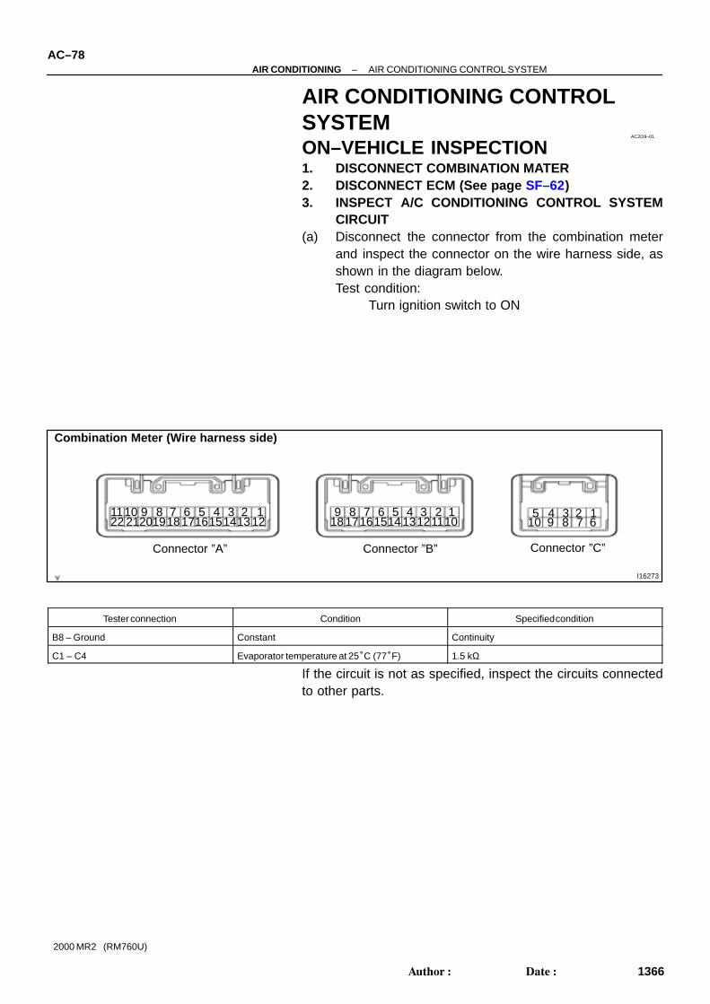
Combination Meter (Wire harness side)
Connector ”A” Connector ”B” Connector ”C”
1619 171820 151421 13211 5
1210 39 4 18 7
226
161718 1514132
115
12 1039 4 18 7 6 5
10 94
8 7 6123
AC2O9–01
AC–78–AIR CONDITIONING AIR CONDITIONING CONTROL SYSTEM
1366Author: Date:
2000 MR2 (RM760U)
AIR CONDITIONING CONTROLSYSTEMON–VEHICLE INSPECTION1. DISCONNECT COMBINATION MATER2. DISCONNECT ECM (See page SF–62)3. INSPECT A/C CONDITIONING CONTROL SYSTEM
CIRCUIT(a) Disconnect the connector from the combination meter
and inspect the connector on the wire harness side, asshown in the diagram below.Test condition:
Turn ignition switch to ON
Tester connection Condition Specified condition
B8 – Ground Constant Continuity
C1 – C4 Evaporator temperature at 25°C (77°F) 1.5 kΩ
If the circuit is not as specified, inspect the circuits connectedto other parts.
I16274
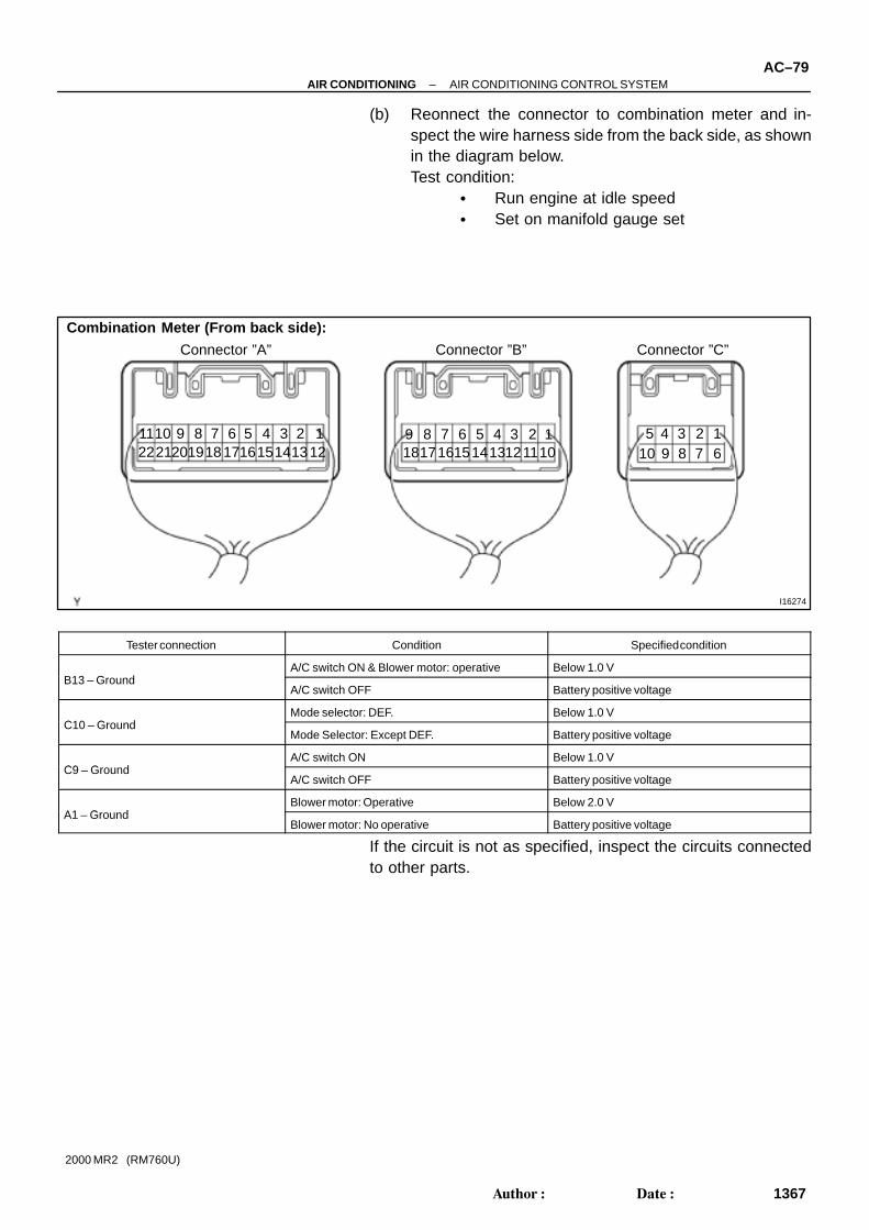
Combination Meter (From back side):
Connector ”A” Connector ”B” Connector ”C”
1619 171820 151421 13211 5
1210 39 4 18 7
226
161718 1514132
115
12 1039 4 18 7 6 5
10 94
8 7 6123
–AIR CONDITIONING AIR CONDITIONING CONTROL SYSTEMAC–79
1367Author: Date:
2000 MR2 (RM760U)
(b) Reonnect the connector to combination meter and in-spect the wire harness side from the back side, as shownin the diagram below.Test condition:
Run engine at idle speed Set on manifold gauge set
Tester connection Condition Specified condition
B13 G dA/C switch ON & Blower motor: operative Below 1.0 V
B13 – GroundA/C switch OFF Battery positive voltage
C10 G dMode selector: DEF. Below 1.0 V
C10 – GroundMode Selector: Except DEF. Battery positive voltage
C9 G dA/C switch ON Below 1.0 V
C9 – GroundA/C switch OFF Battery positive voltage
A1 G dBlower motor: Operative Below 2.0 V
A1 – GroundBlower motor: No operative Battery positive voltage
If the circuit is not as specified, inspect the circuits connectedto other parts.
I16645
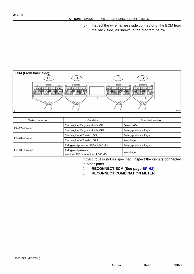
E5
313029 2827171819202122 232425261113141516
12345678910
123456789101112131415
161718192021222324
1234567910111213141516
812 1819
202122
ECM (From back side):
141234568 79
1012131516171819202122
11232425262728
17
E4 E3 E2
AC–80–AIR CONDITIONING AIR CONDITIONING CONTROL SYSTEM
1368Author: Date:
2000 MR2 (RM760U)
(c) Inspect the wire harness side connector of the ECM fromthe back side, as shown in the diagram below.
Tester connection Condition Specified condition
E2 12 G dStart engine. Magnetic clutch: ON Below 1.0 V
E2–12 – GroundStart engine. Magnetic clutch: OFF Battery positive voltage
E3 28 G dStart engine. A/C switch ON Battery positive voltage
E3–28 – GroundStart engine. A/C switch OFF No voltage
Refrigerant pressure: 196 – 1,340 kPa Battery positive voltage
E3–18 – Ground Refrigerant pressure:
less than 196 or more than 1,340 kPaNo voltage
If the circuit is not as specified, inspect the circuits connectedto other parts.4. RECONNECT ECM (See page SF–62)5. RECONNECT COMBINATION METER