air conditioner multi : 2rooms type - goductless conditioner multi : 2rooms type 3rooms ... high...
TRANSCRIPT

AIR CONDITIONER
Multi : 2rooms type 3rooms type 4rooms type
INDOOR
OUTDOOR
DESIGN & TECHNICAL MANUAL
AUU9RLFAUU12RLFAUU18RLF
ARU9RLFARU12RLF
ARU18RLF
AOU18RLXFZAOU24RLXFZ
AOU36RLXFZ
ASU18RLFASU24RLF
ARU24RLF ASU7RLFASU9RLFASU12RLF

1. INDOOR UNITCOMPACT
CASSETTE TYPE : AUU9RLFAUU12RLFAUU18RLF
COMPACT WALL MOUNTED TYPE :
ASU7RLFASU9RLFASU12RLF
SLIM DUCT TYPE :
ARU9RLFARU12RLFARU18RLFARU24RLF
WALL MOUNTED TYPE :ASU18RLFASU24RLF
DTR_MU032E_032011.04.15

MU
LTI T
YPE
2, 3
, 4 R
OO
MS
TYPE
MU
LTI T
YPE
2, 3
, 4 R
OO
MS
TYPE
CONTENTS
1. INDOOR UNIT
1. FEATURE ............................................................................................................... 01 - 011-1. INDOOR UNIT .................................................................................................... 01 - 01
1-1-1. COMPACT CASSETTE TYPE ................................................................... 01 - 01
1-1-2. SLIM DUCT TYPE ...................................................................................... 01 - 02
1-1-3. COMPACT WALL MOUNTED TYPE ........................................................ 01 - 03
1-1-4. WALL MOUNTED TYPE ............................................................................ 01 - 04
1-2. LINE UP .............................................................................................................. 01 - 05
2. REMOTE CONTROLLER .......................................................................... 01 - 072-1. WIRELESS REMOTE CONTROLLER ........................................................... 01 - 07
2-2. WIRED REMOTE CONTROLLER (For Compact cassette type, Slim duct type) ........................................ 01 - 12
3. SPECIFICATIONS ........................................................................................... 01 - 183-1. COMPACT CASSETTE TYPE ......................................................................... 01 - 18
3-2. SLIM DUCT TYPE ............................................................................................. 01 - 19
3-3. COMPACT WALL MOUNTED TYPE ............................................................. 01 - 20
3-4. WALL MOUNTED TYPE .................................................................................. 01 - 21
4. DIMENSIONS .................................................................................................... 01 - 224-1. COMPACT CASSETTE TYPE ......................................................................... 01 - 22
4-2. SLIM DUCT TYPE ............................................................................................. 01 - 24
4-3. COMPACT WALL MOUNTED TYPE ............................................................. 01 - 29
4-4. WALL MOUNTED TYPE ................................................................................. 01 - 31
5. WIRING DIAGRAMS .................................................................................... 01 - 335-1. COMPACT CASSETTE TYPE ......................................................................... 01 - 33
5-2. SLIM DUCT TYPE ............................................................................................. 01 - 34
5-3. COMPACT WALL MOUNTED TYPE ............................................................. 01 - 35
5-4. WALL MOUNTED TYPE .................................................................................. 01 - 36
6. AIR VELOCITY AND TEMPERATURE DISTRIBUTIONS 01 - 376-1. COMPACT CASSETTE TYPE ........................................................................ 01 - 37
6-2. COMPACT WALL MOUNTED TYPE ............................................................. 01 - 43
7. FAN PERFORMANCE CURVE ............................................................. 01 - 487-1. SLIM DUCT TYPE ............................................................................................. 01 - 48
8. AIR FLOW ............................................................................................................ 01 - 56

MU
LTI T
YPE
2, 3
, 4 R
OO
MS
TYPE
MU
LTI T
YPE
2, 3
, 4 R
OO
MS
TYPE
CONTENTS
1. INDOOR UNIT
9. NOISE LEVEL CURVE ................................................................................ 01 - 589-1. COMPACT CASSETTE TYPE ......................................................................... 01 - 58
9-2. SLIM DUCT TYPE ............................................................................................. 01 - 60
9-3. COMPACT WALL MOUNTED TYPE ............................................................. 01 - 62
9-4. WALL MOUNTED TYPE .................................................................................. 01 - 64
9-5. SOUND LEVEL CHECK POINT ..................................................................... 01 - 65
10. ELECTRIC CHARACTERISTICS ........................................................ 01 - 67
11. SAFETY DEVICES .......................................................................................... 01 - 68
12. EXTERNAL INPUT & OUTPUT ............................................................ 01 - 6912-1. EXTERNAL INPUT ............................................................................................ 01 - 69
12-2. EXTERNAL OUTPUT ....................................................................................... 01 - 72
13. FUNCTION SETTING ................................................................................... 01 - 7513-1. INDOOR UNIT (setting by jumper wire) ...................................................... 01 - 75
13-2. INDOOR UNIT (setting by wireless remote controller) .......................... 01 - 76
13-3. INDOOR UNIT (setting by wired remote controller) ................................ 01 - 82
13-4. INDOOR UNIT (setting by simple remote controller) .............................. 01 - 86
13-5. FUNCTION DETAILS ........................................................................................ 01 - 90
13-6. WIRED REMOTE CONTROLLER .................................................................. 01 - 93
13-7. SIMPLE REMOTE CONTROLLER ................................................................. 01 - 96
14. OPTIONAL PARTS ......................................................................................... 01 - 9914-1. CONTROLLER .................................................................................................. 01 - 99
14-2. OTHERS ........................................................................................................... 01 - 100
15. INSTALLATION PRECAUTIONS ....................................................... 01 - 10315-1. INDOOR UNIT INSTALLATION PRECAUTIONS ...................................... 01 - 103

- (01 - 01) -
MU
LTI T
YPE
2, 3
, 4 R
OO
MS
TYPE
MU
LTI T
YPE
2, 3
, 4 R
OO
MS
TYPE
FEATURE1. INDOOR UNIT1-1.
COMPACT CASSETTE TYPE1-1-1. MODELS : AUU9RLF, AUU12RLF, AUU18RLF �
FEATURES �2-stage turbo fan �
High efficiency design by 2 stage structure
+2 stage
Previous turbo fanIn the case of a conventional fan, the air outlet range was narrow as the airflow moved to the motor side which meant the velocity of air passing through the heat exchanger was uneven.
2-stage turbo fanA evenly spread air distribution across the heat exchanger is possible due to the new 2 stage turbo fan which produces two separate airflow streams.
Heat exchange efficiency:
20%UP
1-stage
2-stage
Wind velocity
Fast
Slow
Easy maintenance �
1Maintenance of fan motor and fan Maintenance of the fan motor and fan can be done easily after taking off the panel as the bell mouth of the fan
can be removed easily. A : Fan motor B : 2-stage turbo fanC : Bell-mouth D : Panel
2 Long life filter : standard equipment3 Adaptation of transparent drainage parts During installation, maintenance and operation, the drain pump and
kit can be checked easily.
Compact design �
Easy installation by taking off ceiling panel of 23-5/8in. x 23-5/8in.(600mm x 600mm) size
22-7/16in. (570mm)
22-7/16in. (570mm)
High lift drain pump �
27-9/16in. (700mm)
Quiet quality �
Optimization of wing form (laminar wing type) and wing number (7 blades each)
Airflow runs through smoothly along the laminar wing
No airflow separation
Adoption of laminar wing
Spin direction Airflow direction
Quiet
Quiet
Designed by CFD-analysis (fluid) simulations
Laminar wing
A
B
C
D
2
3
1
Grille cover

- (01 - 02) -
MU
LTI T
YPE
2, 3
, 4 R
OO
MS
TYPE
MU
LTI T
YPE
2, 3
, 4 R
OO
MS
TYPE
SLIM DUCT TYPE1-1-2. MODELS : ARU9RLF, ARU12RLF, ARU18RLF, ARU24RLF �
Slim design and wide range of static pressure for flexible installation.
FEATURES �
Slim design �
This model is slim design, it can install atthe place where a ceiling is narrow.
Height
Drain pump built-in
7-25/32 in.(198mm)
Drain port
Drain pump
Compact design �
Condensate lift-up to 33-15/32in. (850mm)
Max.33-15/32 in.(850mm)
Drain hose is standard accessory
Selectable with a wide range of �static pressure
By using DC fan motor, it is possible to change of static pressure range 0 to 0.36in. WG (0 to 90Pa). The change of static pressure range is possible by remote controller.
0
[in.WG (Pa)]
A ir flow rate
Sta
tic p
ress
ure
rang
e
[CFM (m3/h)]
0.36 (90)
* 24 model is 0 to 0.20in.WG (0 to 50Pa)
Air - intake �
Air intake direction can be selected to match the installation site.
Bottom side Back side
Flexible installation �
Ceiling concealed
Wall concealed
Filter (Accessory) �Filter (ARU09/12/18: 2pcs.) ARU24: 3pcs.)

- (01 - 03) -
MU
LTI T
YPE
2, 3
, 4 R
OO
MS
TYPE
MU
LTI T
YPE
2, 3
, 4 R
OO
MS
TYPE
COMPACT WALL MOUNTED TYPE 1-1-3. MODELS : ASU7RLF, ASU9RLF, ASU12RLF �Compact and Stylish design indoor unit
FEATURES �High density heat transfer tube �arrangement
Ø5
Even temperature
Improved the heat exchanger effectiveness
Making the tubeThin: 0.276inch (7mm)
▼ 0.197inch (5mm)
Volume reduction of heat
exchanger: 30%
Filter features �
The filter deodorizes by powerfully decomposing absorbed odors using the oxidizing and reducing effects of ions generated by the ultra-fine particle ceramic.*The filter can be used for approx. 3 years if it is washed under water to restore it's surface action when it is dirty.
Long-life* Ion deodorization filter
Fine dust, invisible mold spores, and harmful microorganisms are absorbed onto the filter by static electricity, and further growth is inhibited and deactivated by the polyphenol ingredient extracted from apples.
Apple-catechin filter
Deodorizing effect (Odor reduction rate)
Testing organization : Environmental Sanitary InspectionCenter
Test method : Deodorization Test
Ammonia
New filter
With no filter
(ppm)1601208040
00 30 60 120
(min.)
Hydrogen sulfate
New filter
With no filter(ppm)1601208040
00 30 60 120
(min.)
Trimethylamine
New filter
With no filter(ppm)1601208040
00 30 60 120
(min.)
Easy maintenance �
Removable & washable panel
Dry operationDry operation removes moisture and keeps the air conditioner clean.
Quiet operation �
Cooling mode (07/09/12 TYPE)
Fan speed Noise level
25dB(A)Quiet
Auto swing louvre �The Auto Swing Louvre function ensures that the air direction corresponds to the mode selected.
Step
Swing
Swing (Cooling)
Swing (Heating)
Wired control compatible �
SET TEMP. START/STOP
Wired remotecontroller
Simple remotecontroller
Wired and wireless remote controller are acceptable.
* Optional communication kit is neccesary for the installation.
*
- (01 - 04) -
MU
LTI T
YPE
2, 3
, 4 R
OO
MS
TYPE
MU
LTI T
YPE
2, 3
, 4 R
OO
MS
TYPE
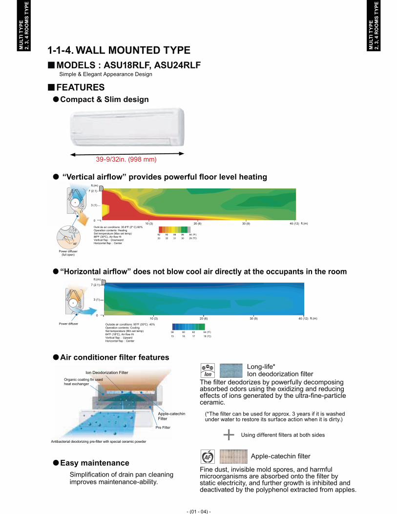
WALL MOUNTED TYPE1-1-4. MODELS : ASU18RLF, ASU24RLF �Simple & Elegant Appearance Design
FEATURES �Compact & Slim design �
39-9/32in. (998 mm)
“Vertical airflow” provides powerful floor level heating �
Outside air conditions: 35.6oF (2o C) 60%
( F)
Operation contents: Heating Set temperature (Max set temp) 86oF (30oC), Air flow Hi
o
( C) o
Vertical flap : DownwardHorizontal flap : Center
Power diffuser(full open)
8492 90 88 862933 32 31 30
OutsidOperaSet te
de air conditionOutsid
46o
(24/30)167 (2.1)
3 (1)
010 (3) 20 (6) 30 (9) 40 (12) ft.(m)
ft.(m)
“Horizontal airflow” does not blow cool air directly at the � occupants in the room
Power diffuser Outside air conditions: 95oF (35oC) 40%
( F)
Operation contents: Cooling Set temperature (Min set temp) 64oF (18oC), Air flow Hi
o
Vertical flap : UpwardHorizontal flap : Center
6458 60 62
( C) o1815 16 17
7 (2.1)
3 (1)
0
ft.(m)
10 (3) 20 (6) 30 (9) 40 (12) ft.(m)
Air conditioner filter features �
Organic coating fin used heat exchanger
Pre Filter
Antibacterial deodorizing pre-filter with special ceramic powder
Ion Deodorization Filter
Apple-catechinFilter
Easy maintenance �
Simplification of drain pan cleaning improves maintenance-ability.
The filter deodorizes by powerfully decomposing absorbed odors using the oxidizing and reducing effects of ions generated by the ultra-fine-particle ceramic.
(*The filter can be used for approx. 3 years if it is washed under water to restore its surface action when it is dirty.)
Using different filters at both sides
Fine dust, invisible mold spores, and harmful microorganisms are absorbed onto the filter by static electricity, and further growth is inhibited and deactivated by the polyphenol extracted from apples.
Long-life* Ion deodorization filter
Apple-catechin filter

- (01 - 05) -
MU
LTI T
YPE
2, 3
, 4 R
OO
MS
TYPE
MU
LTI T
YPE
2, 3
, 4 R
OO
MS
TYPE
LINE UP1-2. MODEL �
INDOOR UNIT
AUU9RLFAUU12RLFAUU18RLF
ARU9RLFARU12RLF
ARU18RLF
ARU24RLF ASU7RLFASU9RLFASU12RLF
ASU18RLFASU24RLF
OUTDOOR UNIT
AOU18RLXFZ AOU24RLXFZ AOU36RLXFZ
Indoor units that can be connected to each outdoor unit �
●:Connectable / -:Not connectable
OUTDOORCOMPACT CASSETTE SLIM DUCT
WALL MOUNTEDCOMPACT
AUU9-18RLF ARU9-24RLF ASU7-24RLFBTU Class 9 12 18 9 12 18 24 7 9 12 18 24
2 Rooms AOU18RLXFZ ● ● - ● ● - - ● ● ● - -3 Rooms AOU24RLXFZ ● ● ● ● ● ● - ● ● ● ● -4 Rooms AOU36RLXFZ ● ● ● ● ● ● ● ● ● ● ● ●

- (01 - 06) -
MU
LTI T
YPE
2, 3
, 4 R
OO
MS
TYPE
MU
LTI T
YPE
2, 3
, 4 R
OO
MS
TYPE
INDOOR UNIT CONNECTION PATTERNS �2 Rooms �
AOU18RLXFZNo. room 1 room 2 total1 7 7 142 7 9 163 7 12 194 9 9 185 9 12 21
Notes) 7: 7000Btu/h / 9: 9000Btu/h / 12: 12000Btu/h models
3 Rooms �
AOU24RLXFZNo. room 1 room 2 room 3 total1 7 7 - 142 7 9 - 163 7 12 - 194 7 18 - 255 9 9 - 186 9 12 - 217 9 18 - 278 12 12 - 249 7 7 7 2110 7 7 9 2311 7 7 12 2612 7 9 9 2513 9 9 9 27
Notes) 7: 7000Btu/h / 9: 9000Btu/h / 12: 12000Btu/h / 18: 18000Btu/h models
4 Rooms �
AOU36RLXFZNo. room 1 room 2 room 3 room 4 total1 18�1 18�1 - - 362 7 7 18 - 323 7 7 24 - 384 7 9 12 - 285 7 9 18 - 346 7 12 12 - 317 7 12 18 - 378 9 9 9 - 279 9 9 12 - 3010 9 9 18 - 3611 9 12 12 - 3312 9 12 18 - 3913 12 12 12 - 3614 7 7 7 7 2815 7 7 7 9 3016 7 7 7 12 3317 7 7 7 18�2 3918 7 7 9 9 3219 7 7 9 12 3520 7 7 12 12 3821 7 9 9 9 3422 7 9 9 12 3723 9 9 9 9 36
Notes) 7: 7000Btu/h / 9: 9000Btu/h / 12: 12000Btu/h / 18: 18000Btu/h / 24: 24000Btu/h models�1: The optional kit "K9FZ1818 (UTP-MU36A2)" shall be necessary for the dual zone system "18+18".�2: Wall mounted type ASU18RLF can not be connected in this combination.

- (01 - 07) -
MU
LTI T
YPE
2, 3
, 4 R
OO
MS
TYPE
MU
LTI T
YPE
2, 3
, 4 R
OO
MS
TYPE
REMOTE CONTROLLER2. WIRELESS REMOTE CONTROLLER2-1.
FEATURES �
Built-in timers �
Select from four different timer programs (ON / OFF / PROGRAM / SLEEP).
Program timer �
The program timer operates the ON and OFF timer once within a 24 hour period.
Sleep timer �
The sleep timer function automatically corrects the temperature thermostat setting according to the time setting to prevent excessive cooling and heating while sleeping.
60min.
2°F (1°C) 4°F (2°C)
Timer setting 2°F (1°C) 4°F (2°C) 6°F (3°C)
8°F (4°C)
30min.
60min.
90min.Timer setting
Cooling operation / dry operationWhen the sleep timer is set, the set temperature automatically rises 2°F (1°C) every hour. The settemperature can rise up to a maximum of 4°F (2°C).
Heating operationWhen the sleep timer is set, the set temperatureautomatically drops 2°F (1°C) every 30 minutes. The set temperature can drop to a maximum of 8°F (4°C).
Switching remote controller signal code �
A B C D
A B C D
Mixed-upI.U. I.U. I.U. I.U. I.U. I.U. I.U. I.U.
After code change
Code selector switch eliminates unit •being wrongly switched. (Up to 4 codes can be set.)
*I.U.=Indoor unit
Four kinds of timer setup (ON / OFF / PROGRAM / SLEEP) are ●possible.Can be used jointly with wired remote controllers . ●Easy to change signal code (4 patterns). ●

- (01 - 08) -
MU
LTI T
YPE
2, 3
, 4 R
OO
MS
TYPE
MU
LTI T
YPE
2, 3
, 4 R
OO
MS
TYPE
MODE button1 Selects the operating mode (AUTO, COOL, DRY, FAN, HEAT). /Start / end R.C. signal code change. (Max 4 types)
MIN.HEAT button2
SET TEMP. button ( ▲ / ▼ )3 Sets the indoor temp./ Sets R.C. signal code.
ECONOMY button4
SLEEP button5 Pressed to select sleep timer.
FAN button6 Selects the fan speed (AUTO, HIGH, MED, LOW, QUIET).
START/STOP button7 Pressed to start and stop operation.
SET button (Vertical)8 Air flow direction vertical set button.
SET button (Horizontal)9 Air flow direction horizontal set button.
SWING button10 Air flow direction swing button.
TIMER MODE button11 Pressed to select the timer mode. (OFF TIMER, ON TIMER,PROGRAM TIMER, TIMER RESET)
TIMER SET ( + / - ) button12 Sets the current time and on-off time.
CLOCK ADJUST button13 Sets the current time.
RESET button14 Used when replacing batteries.
TEST RUN button15 Used when testing the air conditioner after installation.
Signal transmitter16
Temperature set display17
Operating mode display18
Sleep display19
Transmit indicator20
Fan speed display21
Swing display22
Timer mode display23
Clock display24
FUNCTIONS (Wall mounted type) �
Display panel
Note: Functions will be different due to type of indoor unit. For details, please see operation manual.
2
4 9
3
1
16
15
5 10
13
11
12
14
8
7
6
17
18
19
21
24
23
22
20

- (01 - 09) -
MU
LTI T
YPE
2, 3
, 4 R
OO
MS
TYPE
MU
LTI T
YPE
2, 3
, 4 R
OO
MS
TYPE
MODE button1 Selects the operating mode (AUTO, COOL, DRY, FAN, HEAT). /Start / end R.C. signal code change. (Max 4 types)
MIN.HEAT button2
SET TEMP. button ( ▲ / ▼ )3 Sets the indoor temp./ Sets R.C. signal code.
ECONOMY button4
SLEEP button5 Pressed to select sleep timer.
FAN button6 Selects the fan speed (AUTO, HIGH, MED, LOW, QUIET).
START/STOP button7 Pressed to start and stop operation.
SET button (Vertical)8 Air flow direction vertical set button.
SWING button9 Air flow direction swing button.
TIMER MODE button10 Pressed to select the timer mode. (OFF TIMER, ON TIMER,PROGRAM TIMER, TIMER RESET)
TIMER SET ( + / - ) button11 Sets the current time and on-off time.
CLOCK ADJUST button12 Sets the current time.
RESET button13 Used when replacing batteries.
TEST RUN button14 Used when testing the air conditioner after installation.
Signal transmitter15
Temperature set display16
Operating mode display17
Sleep display18
Transmit indicator19
Fan speed display20
Swing display21
Timer mode display22
Clock display23
FUNCTIONS (Compact wall mounted type) �
Display panel
Note: Functions will be different due to type of indoor unit. For details, please see operation manual.
2
4
9
3
1
15
5
10
13
11
12
14
8
7
6
16
17
18
19
21
23
22
20

- (01 - 10) -
MU
LTI T
YPE
2, 3
, 4 R
OO
MS
TYPE
MU
LTI T
YPE
2, 3
, 4 R
OO
MS
TYPE
SYSTEM DIAGRAM �
Signal transmitter Signal receiverwindow
Control signal might not be recognized in following cases: ● (i) A curtain or a wall, etc. exists between transmitter and receiver. (ii) There is an instant-start type (inverter type, etc.) fluorescent lamp in the room.
Air conditioner might not work correctly when strong light hits the ●signal receiver window. Shut off the direct sunlight and also make illuminator far away from the receiver window.
DIMENSIONS �Controller �
6-11
/16
(170
)
2-7/32 (56) 3/4 (19)
Front View Rear View
Top View
Side View
Unit : in. (mm)
Holder �
Front View Side View Bottom View
2-3/8 (60.4)1-3/16 (30.2)
Ø1/8 (3.5)
1/8 x 1/4 (3.5 x 6.5)
(HOLE)
(HOLE)
1-1/32 (26.2)
1 (2
5.5)
3-3/
4 (9
5)
6-3/
32 (1
54.7
)

- (01 - 11) -
MU
LTI T
YPE
2, 3
, 4 R
OO
MS
TYPE
MU
LTI T
YPE
2, 3
, 4 R
OO
MS
TYPE
PACKING LIST �
Name and shape Quantity Application
Remote controller holder 1Use as remote controller holder
Tapping screw 2For remote controller holder installation
Battery[ 1.5V (R03 / AAA) ]
2 For remote controller
SPECIFICATIONS �
Dimensions [H x W x D]: in. (mm) 6-11/16 (170) x 2-7/32 (56) x 3/4 (19)
Weight : oz. (g) 3 (85) [w/o batteries]

- (01 - 12) -
MU
LTI T
YPE
2, 3
, 4 R
OO
MS
TYPE
MU
LTI T
YPE
2, 3
, 4 R
OO
MS
TYPE
WIRED REMOTE CONTROLLER 2-2. (For Compact cassette type, Slim duct type)
FEATURES �
Powerful features and compact size �
Thermosensor
Individual control
Weeklytimer
Setbacktimer
Wiredremote
controller
Sensor part
Thermo sensordisplay
Control part forchanging thethermo sensor
Accurate and comfortable �Indoor temperature can be detected accurately by the inclusion of a thermo sensor in the body of the wired controller.Our system can correspond to various scenes.This wired remote controller and the optional remote sensor allows flexibility in sensor location, and suitable for all requirements.
Built-in timers �Weekly timer Setback timerPossible to set ON/OFF time to operate twice each day of the week.
Possible to set temperature for two time spans and for each day of the week.
At "Weekly timer" + "Set back timer" setup
76°F (24°C)
0 3 6 9 12 15 18 21O'clock12 3 6 9 12 3 6 9time
AM PM
Easy-to-understand time bar display
Example : setup screen (Set to Wednesday: 8:00 to 20:00.)
Screenafter setup
84°F (28°C)
0 3 6 9 12 15 18 21O'clock12 3 6 9 12 3 6 9time
AM PM
Example : setup screen (Set from Sunday to Saturday: 12:00 to 15:00, 28 °C.)
76°F 84°F 76°F0 3 6 9 12 15 18 21
O'clock12 3 6 9 12 3 6 9time
AM PM
76°F (24°C)84°F (28°C)
24°C 28°C 24°C
Easy-to-understand operation �
[Variable timer control]The operation/display sections are zoned accordingto time and operation, enabling variable programmingto match application.
Simple installation �Components are compatible with standard switch boxes. Flat back surface allows equipment to be installed wherever it is needed.
Timerarea
Operationarea
Europeanswitch box
JIS box
Various timer setup (ON / OFF / WEEKLY) are possible. ●Equipped with weekly timer as standard function. ●(Start / Stop function is twice per day for a week)When setting up a timer, start / stop and a temperature setup can ●be changed.When a failure occurs,the error code is displayed. ●Error history.(Last 16 error codes can be accessed.) ●The room temperature can be controlled by being detective the ●temperature accurately with Built-in thermo sensor.

- (01 - 13) -
MU
LTI T
YPE
2, 3
, 4 R
OO
MS
TYPE
MU
LTI T
YPE
2, 3
, 4 R
OO
MS
TYPE
START/STOP button1 Pressed to start and stop operation.
SET TEMP. button2 Selects the setting temperature.
MODE button3 Selects the operating mode ( AUTO , COOL , DRY ,
FAN , HEAT ).
FAN button4 Selects the fan speed ( AUTO , HIGH , MED ,
LOW , QUIET ).
Vertical air flow direction and swing button5 Press for two seconds to change the swing mode
Horizontal air flow direction and swing button6 Press for two seconds to change the swing mode.
Built-in thermo sensor7 Detect room temperature.
TIMER MODE (CLOCK ADJUST) button8 Selects the timer mode (OFF TIMER, ON TIMER, WEEKLY TIMER)Set the current time.
DAY (DAY OFF) button9 Temporarily cancels of one day timer.
SET BACK button10 Pressed select the set back timer.
SET TIME button11 Pressed to select the set back timer.
TIMER DELETE button12 The schedule of a weekly timer is deleted.
TIME SET button13 Sets the date, hour, minute and on-off time.
ECONOMY (THERMO SENSOR) button14
FILTER RESET button15
Operation lamp16 Lights during operation and when the timer is on.
Timer and clock display17
Operation mode display18
Fan speed display19
Operation lock display20
Temperature display21 Displayed temperature is set temperature.
Defrost display22 Indicates during the oil recovery and defrosting operation.
Vertical swing display 23
Horizontal swing display 24
Economy display25
Thermo sensor display 26
Filter display27
FUNCTIONS �
Display panel
Note: Functions will be different due to type of indoor unit. For details, please see operation manual.
7
Display
1312
1110
289
16
1514
13
5
46
1817 1920 21
2223 242527 26

- (01 - 14) -
MU
LTI T
YPE
2, 3
, 4 R
OO
MS
TYPE
MU
LTI T
YPE
2, 3
, 4 R
OO
MS
TYPE
SYSTEM DIAGRAM �1 remote controller � �2 remote controllers
Primary Secon-dary
A B C
Indoor unit Indoor unit
Remote controller Remote controllers
A , B , C : Remote controller cable. A < =1640ft (500m) ; B+C < =1640ft (500m)
ELECTRICAL WIRING �1 remote controller � �2 remote controllers
Indoor unit
REMOTECONTROLLER
1 2 3
1 2 3
Primary Secondary
Indoor unit
1 2 3
1 2 3 1 2 3
REMOTECONTROLLER
Remote controller Remote controllers
1 (RED) : 12V2 (WHITE) : Signal3 (BLACK) : COM
DIMENSIONS �
3-9/
32 (8
3.5)
19/3
2 (1
5.3)
2-1
/2 (6
3.5)
Hole
1-25
/32 (4
5.3)
3/16 (
4.5)
3/16 (
4.5)
3/16 (4.5)
11/32 (9)
1/2
(12.
5)
Hole x 2Hole x 3
1/4 (6)
1-3/16 (30) 1-5/16 (33.5)
29/32 (23)
4- 23/32 (120)
4- 2
3/32
(120
)
4- 2
3/32
(120
)
23/32 (18)
Front View Side View Rear View
Unit : in. (mm)

- (01 - 15) -
MU
LTI T
YPE
2, 3
, 4 R
OO
MS
TYPE
MU
LTI T
YPE
2, 3
, 4 R
OO
MS
TYPE
INSTALLATION �Connection Pattern �
Note: Connection pattern is different according to type of Indoor unit.Indoor unit types Connection Pattern
Compact Cassette type Pattern ASlim Duct typeCompact Wall Mounted type Pattern B
Wall Mounted type Pattern C
Pattern A �
Connect the end of remote controller cable directly to the exclusive terminal block.
PCB
M4 screw
Terminal block
Remote controller cable
Remote controller terminal block Indoor unit
Outdoor unit / Power supply terminal block
Note: It may be failed if it is connected to the outdoor unit or the terminal block for power supply.
Pattern B �
1) Modify the remote controller cable as per below methods.Use a tool to cut off the terminal on the end of the remote controller cable and then remove ●the insulation from the cut end of the cable as shown in Fig.Connect the remote controller cable and connecting cable as shown in Fig. ●Be sure to insulate the connection between the cables. ●
25/3
2 in
.(2
0 m
m)
Remote controller cable
Connecting cable
Insulated connection
Red
Red
White
White
Black
Black
2) Method of connecting remote controller cableConnecting cable made by above-mentioned 1) is connected with terminal (CN305) of ●optional communication kit (UTY-XCBXZ1).Cable connected with terminal (CN301) of communication kit (UTY-XCBXZ1) is connected ●with PCB of Indoor unit.
Remote controller cable
Connecting cable
Communication kit(UTY-XCBXZ1)
Indoor unit PCB
Terminal(CN301)
Terminal(CN305)

- (01 - 16) -
MU
LTI T
YPE
2, 3
, 4 R
OO
MS
TYPE
MU
LTI T
YPE
2, 3
, 4 R
OO
MS
TYPE
Pattern C �
1) Modify the remote controller cable as per below methods.Use a tool to cut off the terminal on the end of the remote controller cable and then remove ●the insulation from the cut end of the cable as shown in Fig.Connect the remote controller cable and connecting cable as shown in Fig. ●Be sure to insulate the connection between the cables. ●
25/3
2 in
.(2
0 m
m)
Remote controller cable
Connecting cable
Insulated connection
Red
Red
White
White
Black
Black
2) Method of connecting remote controller cableConnecting cable made by above-mentioned 1) is connected with PCB of Indoor unit. ●
CN6Remote controller cable
Connecting cable
Indoor unit PCB

- (01 - 17) -
MU
LTI T
YPE
2, 3
, 4 R
OO
MS
TYPE
MU
LTI T
YPE
2, 3
, 4 R
OO
MS
TYPE
PACKING LIST �
Name and shape Quantity Application
Remote controller cable
[33ft(10m)] 1
For connecting the remote controller
Screw(M4 x 16mm)
2For installing the remote controller
Binder 1For remote controller and remote controller cable binding
Connecting cable *1 1For connecting the remote controller cable to the Compact wall mounted type and Wall mounted type indoor unit
Screw *1(M4 x 14mm)
1For installing the remote controller cable to the indoor unit
Cable clamper *1 1 For installing the remote controller cable to the indoor unit
Installation manual 1
Operating manual 1
*1: Use only if the remote controller cable must be modified for the indoor unit model.
WIRING SPECIFICATIONS �Use Cable size Wire type Remarks
Remote controller cable
22AWG( 0.33 mm2 ) Polar 3 core Use sheathed PVC cable
SPECIFICATIONS �
Dimensions [H x W x D]: in.(mm) 4-23/32 (120) x 4-23/32 (120) x 23/32 (18)
Weight: oz. (g) 5.6 (160)
PART (OPTIONAL) �
Compact wall mounted
Model name UTY-XCBXZ1
* The communication kit (UTY-XCBXZ1) is needed for connecting the wired remote controller to the Compact wall mounted type.

- (01 - 18) -
MU
LTI T
YPE
2, 3
, 4 R
OO
MS
TYPE
MU
LTI T
YPE
2, 3
, 4 R
OO
MS
TYPE
SPECIFICATIONS3. COMPACT CASSETTE TYPE3-1.
Model name AUU9RLF AUU12RLF AUU18RLFPower source 1ø 208/230V 60HzAvailable voltage range 187-264VCapacity 9,000 BTU/h class 12,000 BTU/h class 18,000 BTU/h classInput power W 18 23 39Running current A 0.15 0.19 0.30
Fan
Airflow rate
Cooling
High
CFM (m3/h)
318 (540) 359 (610) 441 (750)Med 288 (490) 312 (530) 359 (610)Low 259 (440) 277 (470) 306 (520)Quiet 230 (390) 241 (410) 241 (410)
Heating
High 318 (540) 359 (610) 471 (800)Med 288 (490) 312 (530) 418 (710)Low 259 (440) 277 (470) 353 (600)Quiet 230 (390) 241 (410) 265 (450)
Fan Type × Q'ty Turbo × 1Fan Motor Output W 42 42 42
Sound pressure level
Cooling
High
dB(A)
33 37 42Med 31 33 37Low 29 31 33Quiet 27 28 29
Heating
High 34 37 44Med 32 33 40Low 29 31 37Quiet 27 28 30
Heat exchanger
Dimension (H×W×D) in.(mm) 8-9/32 × 51-9/16 × 17/32 + 8-9/32 × 49-7/32 × 17/32 (210×1310×13.3 + 210×1250×13.3)
Fin pitch FPI 21Rows × Stages 2×10Pipe type Copper tubeFin Type Aluminum
EnclosureMaterial PS
Color WHITE (Approximate color of MUNSELL N9.25 /)
Dimensions ( H×W×D )
NetUnit
in.(mm)
9-21/32 × 22-7/16 × 22-7/16 (245×570×570)Panel 1-15/16 × 27-9/16 × 27-9/16 (49 × 700 × 700)
GrossUnit 10-7/16 × 28-3/4 × 24-19/32 (265×730×625)Panel 4-23/32 × 30-1/8 × 29-23/32 (120 × 765 × 755)
WeightNet
Unit
lbs.(kg)
33 (15)Panel 5.7(2.6)
GrossUnit 40 (18)Panel 10(4.5)
Connection pipe
SizeLiquid
in.(mm)Φ1/4 (Φ6.35)
Gas Φ3/8 (Φ9.52) Φ1/2 (Φ12.7)Method Flare
Drain pipeMaterial HARD PVC
size in.Outer Diameter : 1-1/16
Inner Diameter : 3/4
Operation rangeCooling
°F (°C) 64 to 90 (18 to 32)%RH 80 or less
Heating °F (°C) 60 to 88 (16 to 31)Remote controller type Wired [Wireless(option)]
Note: The protective function might work when using it outside the operation range.

- (01 - 19) -
MU
LTI T
YPE
2, 3
, 4 R
OO
MS
TYPE
MU
LTI T
YPE
2, 3
, 4 R
OO
MS
TYPE
SLIM DUCT TYPE3-2. Model name ARU9RLF ARU12RLF ARU18RLF ARU24RLFPower source 1ø 208/230V 60HzAvailable voltage range 187-264VCapacity 9,000 BTU/h class 12,000 BTU/h class 18,000 BTU/h class 24,000 BTU/h classInput power W 49 58 73 111Running current A 0.30 0.35 0.44 0.66
Fan
Airflow rate
Cooling
High
CFM (m3/h)
353 (600) 383 (650) 554 (940) 783 (1330)Med 324 (550) 353 (600) 518 (880) 730 (1240)Low 294 (500) 324 (550) 483 (820) 648 (1100)Quiet 265 (450) 283 (480) 442 (750) 607 (1030)
Heating
High 353 (600) 383 (650) 554 (940) 783 (1330)Med 324 (550) 353 (600) 518 (880) 730 (1240)Low 294 (500) 324 (550) 483 (820) 648 (1100)Quiet 265 (450) 283 (480) 442 (750) 607 (1030)
Fan type ×Q'ty Sirocco × 2 Sirocco × 3 Sirocco × 4Fan motor output W 81 81 96 96
Recommended static pressure in.WG(Pa) 0 to 0.36 (0 to 90) 0 to 0.36 (0 to 90) 0 to 0.36 (0 to 90) 0 to 0.20 (0 to 50)
Sound pressure level
Cooling
High
dB(A)
28 29 32 33Med 27 28 31 32Low 26 27 30 30Quiet 25 26 29 29
Heating
High 28 29 33 35Med 26 28 32 34Low 25 27 31 32Quiet 24 24 29 29
Heat exchanger
Dimension (H×W×D) in.(mm) 11-9/16 × 19-11/16 × 1-9/16 (294×500×39.9)
11-9/16 × 27-9/16 × 1-9/16
(294×700×39.9)
11-9/16 × 35-7/16 × 1-9/16
(294×900×39.9)Fin pitch FPI 20Rows × Stages 3 × 14Pipe type Copper tubeFin Type Aluminum
EnclosureMaterial GALVANIZED STEEL SHEETColor -
Dimensions ( H×W ×D )
Net
in.(mm)
7-25/32 x 27-9/16 x 24-13/32(198 × 700 × 620)
7-25/32 x 35-7/16 x 24-13/32
(198 × 900 × 620)
7-25/32 x 43-5/16 x 24-13/32
(198 × 1100 × 620)
Gross 10-7/8 x 38-1/8 x 29-3/4(276 × 968 × 756)
10-7/8 x 46 x 29-3/4(276 × 1168 × 756)
10-7/8 x 53-27/32 x 29-3/4
(276 × 1368 × 756)
WeightNet
lbs.(kg)41 (19) 50 (23) 59 (27)
Gross 58 (26) 67 (30) 75 (34)
Connection pipe
SizeLiquid
in.(mm)Φ1/4 (Φ6.35)
Gas Φ3/8 (Φ9.52) Φ1/2 (Φ12.7) Φ5/8 (Φ15.88)Method Flare
Drain pipeMaterial HARD PVC
size in.Outer Diameter : 1-1/16
Inner Diameter : 3/4
Operation rangeCooling
°F (°C) 64 to 90 (18 to 32)%RH 80 or less
Heating °F (°C) 60 to 88 (16 to 31)Remote controller type Wired [Wireless(option)]
Note: Specifications are based on the following conditions.
Standard static pressure : 0.10in.WG (25Pa)The protective function might work when using it outside the operation range.

- (01 - 20) -
MU
LTI T
YPE
2, 3
, 4 R
OO
MS
TYPE
MU
LTI T
YPE
2, 3
, 4 R
OO
MS
TYPE
COMPACT WALL MOUNTED TYPE3-3. Model name ASU7RLF ASU9RLF ASU12RLFPower source 1ø 208/230V 60HzAvailable voltage range 187-264VCapacity 7,000 BTU/h class 9,000 BTU/h class 12,000 BTU/h classInput power W 15 17 22Running current A 0.13 0.15 0.19
Fan
Airflow rate
Cooling
High
CFM (m3/h)
330 (560) 353 (600) 388 (660)Med 294 (500) 306 (520) 330 (560)Low 253 (430) 253 (430) 265 (450)Quiet 200 (340) 200 (340) 200 (340)
Heating
High 330 (560) 353 (600) 388 (660)Med 294 (500) 306 (520) 330 (560)Low 253 (430) 253 (430) 277 (470)Quiet 206 (350) 206 (350) 206 (350)
Fan type × Q'ty Cross Flow ×1Fan motor output W 30 30 30
Sound pressure level
Cooling
High
dB(A)
36 37 40Med 32 33 36Low 29 29 30Quiet 25 25 25
Heating
High 36 37 40Med 32 33 36Low 29 29 31Quiet 25 25 25
Heat exchanger
Dimension (H×W×D) in.(mm) Main: 12-19/32 x 24-13/16 x 25/32 (320 x 630 x 20)Sub: 3-5/16 x 24-13/16 x 17/32 (84 x 630 x 13.3)
Fin pitch FPI Main: 23, Sub: 18Rows × Stages Main: 2 x 20, Sub: 1 x 4Pipe type Copper tubeFin Type Aluminum
EnclosureMaterial Polystyrene
Color WHITE (Approximate color of MUNSELL N9.25 /)
Dimensions ( H×W ×D )
Netin.(mm)
11-1/16 × 31-1/16 × 8 (280×790×203)Gross 10-3/8 × 33-1/16 × 14-3/4 (263×840×375)
WeightNet
lbs.(kg)18 (8)
Gross 23 (10.5)
Connection pipe
SizeLiquid
in.(mm)Φ1/4 (Φ6.35)
Gas Φ3/8 (Φ9.52)Method Flare
Drain pipeMaterial PP + LLDPE
size in.(mm)Outer Diameter : 5/8 to 21/32 (15.8 to 16.7)
Inner Diameter : 17/32 (13.8)
Operation rangeCooling
°F (°C) 64 to 90 (18 to 32)%RH 80 or less
Heating °F (°C) 60 to 88 (16 to 31)Remote controller type Wireless [Wired(option)]
Note: The protective function might work when using it outside the operation range.
- (01 - 21) -
MU
LTI T
YPE
2, 3
, 4 R
OO
MS
TYPE
MU
LTI T
YPE
2, 3
, 4 R
OO
MS
TYPE
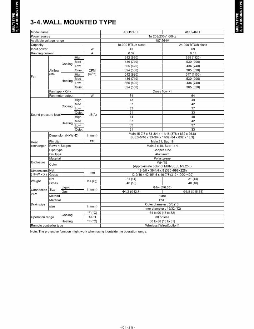
WALL MOUNTED TYPE3-4. Model name ASU18RLF ASU24RLFPower source 1ø 208/230V 60HzAvailable voltage range 187-264VCapacity 18,000 BTU/h class 24,000 BTU/h classInput power W 41 69Running current A 0.32 0.53
Fan
Airflow rate
Cooling
High
CFM (m3/h)
542 (920) 659 (1120)Med 436 (740) 530 (900)Low 365 (620) 436 (740)Quiet 324 (550) 365 (620)
Heating
High 542 (920) 647 (1100)Med 436 (740) 530 (900)Low 365 (620) 436 (740)Quiet 324 (550) 365 (620)
Fan type × Q'ty Cross flow ×1Fan motor output W 64 64
Sound pressure level
Cooling
High
dB(A)
43 49Med 37 42Low 33 37Quiet 31 33
Heating
High 44 48Med 37 42Low 33 37Quiet 31 33
Heat exchanger
Dimension (H×W×D) in.(mm) Main:15-7/8 x 33-3/4 x 1-1/16 (378 x 832 x 26.6) Sub:3-5/16 x 33-3/4 x 17/32 (84 x 832 x 13.3)
Fin pitch FPI Main:21, Sub:18Rows × Stages Main:2 x 18, Sub:1 x 4Pipe type Copper tubeFin Type Aluminum
EnclosureMaterial Polystyrene
Color WHITE (Approximate color of MUNSELL N9.25 /)
Dimensions ( H×W ×D )
Netmm
12-5/8 x 39-1/4 x 9 (320×998×228)Gross 12-9/16 x 42-15/16 x 16-7/8 (319×1090×429)
WeightNet
lbs.(kg)31 (14) 31 (14)
Gross 40 (18) 40 (18)
Connection pipe
SizeLiquid
in.(mm)Φ1/4 (Φ6.35)
Gas Φ1/2 (Φ12.7) Φ5/8 (Φ15.88)Method Flare
Drain pipeMaterial PVC
size in.(mm)Outer diameter : 5/8 (16)
Inner diameter : 15/32 (12)
Operation rangeCooling
°F (°C) 64 to 90 (18 to 32)%RH 80 or less
Heating °F (°C) 60 to 88 (16 to 31)Remote controller type Wireless [Wired(option)]
Note: The protective function might work when using it outside the operation range.

- (01 - 22) -
MU
LTI T
YPE
2, 3
, 4 R
OO
MS
TYPE
MU
LTI T
YPE
2, 3
, 4 R
OO
MS
TYPE
DIMENSIONS4. COMPACT CASSETTE TYPE4-1.
MODELS : AUU9RLF, AUU12RLF, AUU18RLF �
AUU9RLF, AUU12RLF AUU18RLF1 Refrigerant pipe flare
connectionLiquid ø 1/4 in. (6.35 mm) ø 1/4 in. (6.35 mm)
2 Gas ø 3/8 in. (9.52 mm) ø 1/2 in. (12.70 mm)3 Drain hose connection Drain hose I.D. 3/4 in. , O.D. 1-1/16 in.
Unit : in. (mm)
(Drain hose)
20-7/8 (530): Hanging bolt position
4-1/32 (102)
5-5/16 (135) 9-27/32 (250)
27-9/16 (700)
27-9
/16
(700
)
2-15
/16
(75)
1-3/
16 (3
0)
1-3/
16 (3
0)
10-5
/16
(262
)
21-1
/4 (5
40):
Han
ging
bol
t pos
ition
□ 22
-7/1
6 (5
70):
Indo
or u
nit
□ 22
-27/
32 to
26
(580
to 6
60)
: Cei
ling
open
ings
• Decoration panel mounting state
Top view
5-29
/32
to 7
-7/8
(150
to 2
00)
Min
. 17-
23/3
2 (4
50)
Min. 17-23/32 (450)
Maintenance space
Side view
8-15
/32
(215
)
4-27
/32
(123
)
2-9/
32 (5
8)
4-1/
2 (1
14)
5-3/
4 (1
46)
4-1/
4 (1
08)
4-1/32 (102)
9-21
/32
(245
)
1-3/
16 (3
0)
1-9/16 (40) 3-29/32 (99)Drain port
Control boxCeiling
Drain port
Be sure to leave maintenance space for future service at the designated position.
Bottom view
1-3/
16 (3
0)
1-15
/16
(49)
Side view

- (01 - 23) -
MU
LTI T
YPE
2, 3
, 4 R
OO
MS
TYPE
MU
LTI T
YPE
2, 3
, 4 R
OO
MS
TYPE
INSTALLATION PLACE �
39-3/8 (1000)or more
39-3/8 (1000)or more
94-1/2 (2400)or more
10-5/16 (262)or more
Strong and durable ceiling
Obstruction
Floor
H
H (The maximum height from floor to ceiling) Unit: in. (mm)
Model name AUU9 AUU12 AUU18
Standard mode106-5/16
(2700)106-5/16
(2700)106-5/16
(2700)
High Ceiling mode -118-1/8(3000)
118-1/8(3000)
3-way directions setting �
3-15/16 (100) or more*
To set “3-way directions”, the air outlet shutter plate (UTR-YDZB) sold separately must be installed and “outlet-direction” switched to “3-way” by remote controller.*When installing the indoor unit, be careful about the maintenance space.
Unit : in. (mm)

- (01 - 24) -
MU
LTI T
YPE
2, 3
, 4 R
OO
MS
TYPE
MU
LTI T
YPE
2, 3
, 4 R
OO
MS
TYPE
SLIM DUCT TYPE4-2. MODELS : ARU9RLF, ARU12RLF �
Rear viewView A
Top viewSide view
Front viewBottom view
(Drain hose)
Drain port
2 (51)22-19/32 (574)6-
27/3
2 (1
74)
2-25
/32
(71)
6 (1
52)
3-15/16 (100) x 6 = 23-5/8 (600)
3-7/32 (82)
1-7/8 (48)
25-19/32 (650)
28-29/32 (734)
1-3/
16 (3
0)
14-2
7/32
(377
)
6-9/16 (167)
4-11/16 (119)
3-1/2 (89)
3-1/16 (78)2-5/32 (55)
1-27/32 (47)
13/3
2 (1
0)
24-1
3/32
(620
)
14-1
9/32
(371
)
10-1
3/32
(264
)
5-21
/32
(144
)
2-23
/32
(69)
25-19/32 (650)
26-5/32 (664)
27-9/16 (700)
1-11/16 (43)
25/32 (20)
7-25
/32
(198
)
6-5/
8 (1
68)
5-15
/16
(151
)
3-1/
16 (7
8)2-
5/32
(55)
ARU9, ARU121 Refrigerant pipe flare
connectionLiquid ø 1/4 in. (6.35 mm)
2 Gas ø 3/8 in. (9.52 mm)3 Drain hose connection Drain hose I.D. 3/4 in. , O.D. 1-1/16 in.
Unit : in. (mm)

- (01 - 25) -
MU
LTI T
YPE
2, 3
, 4 R
OO
MS
TYPE
MU
LTI T
YPE
2, 3
, 4 R
OO
MS
TYPE
MODEL : ARU18RLF �
Rear viewView A
Top viewSide view
Front view
Bottom view
(Drain hose)
Drain port
2 (51)30-15/32 (774)
6-27
/32
(174
)
2-25
/32
(71) 6 (1
52)
3-7/16 (87)
2-7/32 (56)
33-15/32 (850)
36-25/32 (934)
3-15/16 (100) x 8 = 31-1/2 (800)
1-3/
16 (3
0)14
-27/
32 (3
77)
6-9/16 (167)
4-11/16 (119)
3-1/2 (89)
3-1/16 (78)2-5/32 (55)
1-27/32 (47)
13/3
2 (1
0)
24-1
3/32
(620
)
14-1
9/32
(371
)
10-1
3/32
(264
)
5-21
/32
(144
)
2-23
/32
(69)
33-15/32 (850)
34-1/32 (864)
35-7/16 (900)
1-11/16 (43)
25/32 (20)
7-25
/32
(198
)
6-5/
8 (1
68)
5-15
/16
(151
)3-
1/16
(78)
2-5/
32 (5
5)
ARU181 Refrigerant pipe flare
connectionLiquid ø 1/4 in. (6.35 mm)
2 Gas ø 1/2 in. (12.70 mm)3 Drain hose connection Drain hose I.D. 3/4 in. , O.D. 1-1/16 in.
Unit : in. (mm)

- (01 - 26) -
MU
LTI T
YPE
2, 3
, 4 R
OO
MS
TYPE
MU
LTI T
YPE
2, 3
, 4 R
OO
MS
TYPE
MODEL : ARU24RLF �
Rear view
View A
Top viewSide view
Front view
Bottom view
(Drain hose)
Drain port
38-11/32 (974) 2 (51)6-
27/3
2 (1
74)
2-25
/32
(71)
6 (1
52)
44-21/32 (1134)
2-7/32 (56)
3-7/16 (87)
3-15/16 (100) x 10 = 39-3/8 (1000)
41-11/32 (1050)
1-3/
16 (3
0)
14-2
7/32
(377
)
6-9/16 (167)
4-11/16 (119)
3-1/2 (89)
3-1/16 (78)2-5/32 (55)
1-27/32 (47)
13/3
2 (1
0)
24-1
3/32
(620
)
14-1
9/32
(371
)
10-1
3/32
(264
)
5-21
/32
(144
)
2-23
/32
(69)
43-5/16 (1100)
1-11/16 (43)
25/32 (20)
7-25
/32
(198
)
6-5/
8 (1
68)
5-15
/16
(151
)
3-1/
16 (7
8)2-
5/32
(55)
ARU241 Refrigerant pipe flare
connectionLiquid ø 1/4 in. (6.35 mm)
2 Gas ø 5/8 in. (15.88 mm)3 Drain hose connection Drain hose I.D. 3/4 in. , O.D. 1-1/16 in.
Unit : in. (mm)

- (01 - 27) -
MU
LTI T
YPE
2, 3
, 4 R
OO
MS
TYPE
MU
LTI T
YPE
2, 3
, 4 R
OO
MS
TYPE
INSTALLATION PLACE �
Leftside
Strong and durable ceiling
Indoor unitRightside
3-15/16 (100)or more
11-13/16 (300)or more
Service access Ceiling
98-7
/16
(250
0) o
r mor
e(W
hen
no c
eilin
g)
Floor
9-7/
16 (2
40) o
r mor
e
25/32 (20) or more
25/32 (20) or more
11-13/16 (300) or more
13/32 (10) or less
13/32 (10) or less
Left side
Strong and durable floor
Right side(PIPE side)
Grill
Inlet air
Strong and durable floor
5-29/32 (150)
or more
3-15/16 (100)or more
11-13/16 (300)or more
25/32 (20) or more
25/32 (20) or more
5-29/32 (150)or more
Left side
Strong anddurable floor
Right side (PIPE side)
Dact
Grill
Inlet air
Strong and durable floor
5-29/32 (150)
or more
3-15/16 (100)or more
11-13/16 (300)or more
25/32 (20) or more
25/32 (20) or more
5-29/32 (150)or more
Unit : in. (mm)

- (01 - 28) -
MU
LTI T
YPE
2, 3
, 4 R
OO
MS
TYPE
MU
LTI T
YPE
2, 3
, 4 R
OO
MS
TYPE
MAINTENANCE SPACE �Provide a service access for inspection purposes as shown below.Do not place any wiring or illumination in the service space, as they will impede service.
Service access
Unit
Controlbox
or more
Service space
11-13/16 (300)
11-1
3/16
(300
) o
r mor
e
3-15
/16
(100
) o
r mor
e
Unit : in. (mm)

- (01 - 29) -
MU
LTI T
YPE
2, 3
, 4 R
OO
MS
TYPE
MU
LTI T
YPE
2, 3
, 4 R
OO
MS
TYPE
Unit : in. (mm)
COMPACT WALL MOUNTED TYPE4-3. MODELS : AS � U7RLF, ASU9RLF, ASU12RLF
ASU7RLF, ASU9RLF, ASU12RLF1 Refrigerant pipe flare
connectionLiquid ø 1/4 in. (6.35 mm)
2 Gas ø 3/8 in. (9.52 mm)3 Drain hose connection Drain hose I.D. 17/32 in. (13.8 mm), O.D. 5/8 to 21/32 in. (15.8 to 16.7 mm)
Drain hose : L=20-15/32 in. (520mm)
8-1/16 (205) : Installed state
*1: Vertical flap is downward
8 (203)
5-1/2 (140) *1
13/3
2 (1
0) *
1
5-23/32 (145) *1
31-3/32 (790)
11-1
/32
(280
)
3-11/16 (94)
2-1/16 (52)
3-1/16 (78)
ø2-9/16 (65)for pipe inlet
ø2-9/16 (65)for pipe inlet
Outline of unit
12-23/32 (323)
13-29/32 (353): Gas pipe
16-11/32 (415): Liquid pipe
12-7/8 (327)
9-11/32 (237)
17-23/32 (450)
8-7/32 (209)
2-7/16 (62)
23/32 (18)
1-27
/32
(47)
1-27
/32
(47)
7-1/
4 (1
84)
8-15
/32
(215
)
23/3
2 (1
8)
3-7/
32 (8
2)

- (01 - 30) -
MU
LTI T
YPE
2, 3
, 4 R
OO
MS
TYPE
MU
LTI T
YPE
2, 3
, 4 R
OO
MS
TYPE
Unit : in. (mm)
INSTALLATION PLACE �
59-1/16 (1500) or more
70-7
/8 (1
800)
or m
ore
2-15
/32
(63)
or m
ore
1-25
/32
(45)
or m
ore
1-7/8 (48) or more2-1/16 (52) or more
Outline of unit
2-3/4 (70) or more 3-15/16 (100) or more

- (01 - 31) -
MU
LTI T
YPE
2, 3
, 4 R
OO
MS
TYPE
MU
LTI T
YPE
2, 3
, 4 R
OO
MS
TYPE
Unit : in. (mm)
WALL MOUNTED TYPE 4-4. MODELS : ASU18RLF, ASU24RLF �
ASU18RLF ASU24RLF1 Refrigerant pipe flare
connectionLiquid ø 1/4 in. (6.35 mm) ø 1/4 in. (6.35 mm)
2 Gas ø 1/2 in. (12.70 mm) ø 5/8 in. (15.88 mm)
3 Drain hose connection Drain hose I.D. 15/32 in. (12 mm) , O.D. 5/8 in. (16 mm)Drain hose : L=26-3/8 in. (670mm)
39-9/32 (998)
17-9/32 (439)
17-1/4 (438) 15-5/8 (397)
12-1
9/32
(320
): U
nit s
ize
10-1
9/32
(269
)
25/32 (20)1-15/32 (37)
1-1/32 x 7/16 (26 x 11) hole
6/32 x 23/32 (5 x 18): 14holes
13/16 x 6/32 (21 x 5): 14holes
6/32 x 1-31/32 (5 x 50): 3holes1/2 x 6/32 (13 x 5): 4holes
ø3-5/32 (80) hole
ø6/32 (5): 65holes
39-3/8 (1000): Unit sizePiping inlet
for tapping screw
23/32 x 7/16 (18 x 11) hole
23/32 x 7/16 (18 x 11) hole
4-13/16 (122) 6-25/32 (172)
2-15/16 (75)15-1/4 (387)
6-11/16 (170)
5/8 (16)15-3/4 (400)Unit center
4-31/32 (126)5-1/4 (133)
5-1/8 (130)
4-7/16 (113)
2-15/16 (75)
9-9/16 (243)
8-31/32 (228)
12-1
9/32
(320
)
20-15/32 (520)
20-15/32 (520)
23-7/32 (590)28-3/8 (721)
ø3-5/32 (80) holePiping inlet
1-6/
32 (3
0)
1-6/32 (30)
5-7/
8 (1
49)
7-3/
4 (1
97)
10-2
3/32
(272
)
1-23/32 (44)15/3
2 (1
2)
1/2
(13)
1-1/32 x 7/16 (26 x 11) hole
1 (25)
ø1-1
/4 (3
2)ø5
/8 (1
6)ø1
5/32
(12)

- (01 - 32) -
MU
LTI T
YPE
2, 3
, 4 R
OO
MS
TYPE
MU
LTI T
YPE
2, 3
, 4 R
OO
MS
TYPE
INSTALLATION PLACE �Unit : in. (mm)
2-15
/32
(63)
or m
ore
3-5/
32 (8
0) o
r mor
e
2-3/32 (53) or more2-1/16 (52) or more
3-5/32 (80) or more
Outline of unit
4-23/32 (120) or more
59-1/16 (1500) or more
70-7
/8 (1
800)
or m
ore
- (01 - 33) -
MU
LTI T
YPE
2, 3
, 4 R
OO
MS
TYPE
MU
LTI T
YPE
2, 3
, 4 R
OO
MS
TYPE
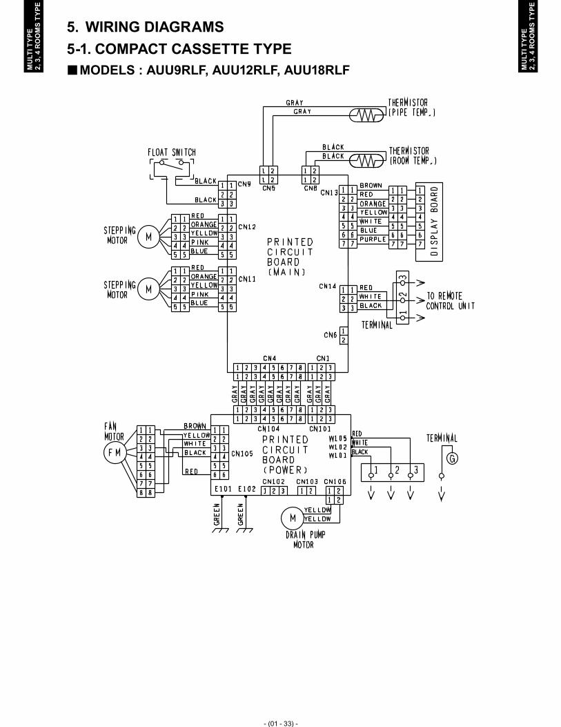
WIRING DIAGRAMS5. COMPACT CASSETTE TYPE5-1.
MODELS : AUU9RLF, AUU12RLF, AUU18RLF �

- (01 - 34) -
MU
LTI T
YPE
2, 3
, 4 R
OO
MS
TYPE
MU
LTI T
YPE
2, 3
, 4 R
OO
MS
TYPE
SLIM DUCT TYPE5-2. MODELS : ARU9RLF, ARU12RLF, ARU18RLF, ARU24RLF �

- (01 - 35) -
MU
LTI T
YPE
2, 3
, 4 R
OO
MS
TYPE
MU
LTI T
YPE
2, 3
, 4 R
OO
MS
TYPE
COMPACT WALL MOUNTED TYPE5-3. MODELS : AS � U7RLF, ASU9RLF, ASU12RLF

- (01 - 36) -
MU
LTI T
YPE
2, 3
, 4 R
OO
MS
TYPE
MU
LTI T
YPE
2, 3
, 4 R
OO
MS
TYPE
WALL MOUNTED TYPE5-4. MODELS : AS � U18RLF, ASU24RLF

- (01 - 37) -
MU
LTI T
YPE
2, 3
, 4 R
OO
MS
TYPE
MU
LTI T
YPE
2, 3
, 4 R
OO
MS
TYPE
AIR VELOCITY AND TEMPERATURE DISTRIBUTIONS6. COMPACT CASSETTE TYPE6-1.
MODEL : AUU9RLF �Air velocity distribution �Top viewVertical flap : Up
7 (2.0)7 (2.0)
7 (2.0)7 (2.0)
3 (1.0)
3 (1.0)
3 (1.0)
3 (1.0)
2 (0.5)
2 (0.5)
2 (0.5)
2 (0.5)
1 (0.25)
1 (0.25)
1 (0.25)
1 (0.25)
Unit : ft./s (m/s)(m)(ft.)
00
3
3
7
7
10
10
13
13
1
1
2
2
3
3
4
4(m)
(ft.)0
0
11
33 77 1010 1313
22 33 44
Side viewVertical flap : Up
7 (2.0)
3 (1.0)
2 (0.5) 2 (0.5)
1 (0.25) 1 (0.25)
Unit : ft./s (m/s)(m)(ft.)
00
3
7
9
1
2
2.7
(m)
(ft.)0
0
11
33 77 1010 1313
22 33 44
Conditions Fan speed : High Operation mode : FAN

- (01 - 38) -
MU
LTI T
YPE
2, 3
, 4 R
OO
MS
TYPE
MU
LTI T
YPE
2, 3
, 4 R
OO
MS
TYPE
Air velocity distribution �Side viewVertical flap : Down
7 (2.0) 7 (2.0)
5 (1.5) 5 (1.5)
3 (1.0) 3 (1.0)
2 (0.5) 2 (0.5)
1 (0.25) 1 (0.25)
Unit : ft./s (m/s)(m)(ft.)
00
3
7
9
8
1
2
2.7
2.5
(m)
(ft.)0
0
11
33 77 1010 1313
22 33 44
Air temperature distribution �Side viewVertical flap : Down
86 (30) 86 (30)
82 (28) 82 (28)
79 (26) 79 (26)
75 (24) 75 (24)
72 (22) 72 (22)
Unit : °F (°C)(m)(ft.)
00
3
7
9
8
1
2
2.7
2.5
(m)
(ft.)0
0
11
33 77 1010 1313
22 33 44
Note: Reference dataConditions Fan speed : High Operation mode : Heating Vertical flap: Downward (4Way)
- (01 - 39) -
MU
LTI T
YPE
2, 3
, 4 R
OO
MS
TYPE
MU
LTI T
YPE
2, 3
, 4 R
OO
MS
TYPE
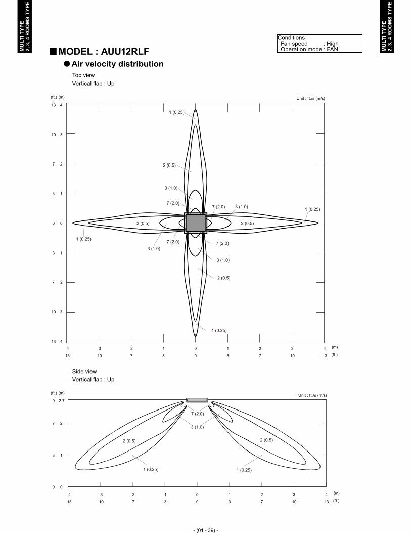
MODEL : AUU12RLF �Air velocity distribution �Top viewVertical flap : Up
7 (2.0) 7 (2.0)
7 (2.0)7 (2.0)
3 (1.0)
3 (1.0)
3 (1.0)
3 (1.0)
2 (0.5)
2 (0.5)
2 (0.5)
2 (0.5)
1 (0.25)
1 (0.25)
1 (0.25)
1 (0.25)
Unit : ft./s (m/s)(m)(ft.)
00
3
3
7
7
10
10
13
13
1
1
2
2
3
3
4
4(m)
(ft.)0
0
11
33 77 1010 1313
22 33 44
Side viewVertical flap : Up
7 (2.0)
3 (1.0)
2 (0.5) 2 (0.5)
1 (0.25) 1 (0.25)
Unit : ft./s (m/s)(m)(ft.)
00
3
7
9
1
2
2.7
(m)
(ft.)0
0
11
33 77 1010 1313
22 33 44
Conditions Fan speed : High Operation mode : FAN

- (01 - 40) -
MU
LTI T
YPE
2, 3
, 4 R
OO
MS
TYPE
MU
LTI T
YPE
2, 3
, 4 R
OO
MS
TYPE
Air velocity distribution �
Side viewVertical flap : Down
5 (1.5) 5 (1.5)
3 (1.0) 3 (1.0)
2 (0.5) 2 (0.5)
1 (0.25) 1 (0.25)
Unit : ft./s (m/s)(m)(ft.)
00
3
7
9
8
1
2
2.7
2.5
(m)
(ft.)0
0
11
33 77 1010 1313
22 33 44
Air temperature distribution �
Side viewVertical flap : Down
86 (30) 86 (30)
82 (28) 82 (28)
79 (26) 79 (26)
75 (24) 75 (24)
72 (22) 72 (22)
Unit : °F (°C)(m)(ft.)
00
3
7
9
8
1
2
2.7
2.5
(m)
(ft.)0
0
11
33 77 1010 1313
22 33 44
Note: Reference dataConditions Fan speed : High Operation mode : Heating Vertical flap: Downward (4Way)
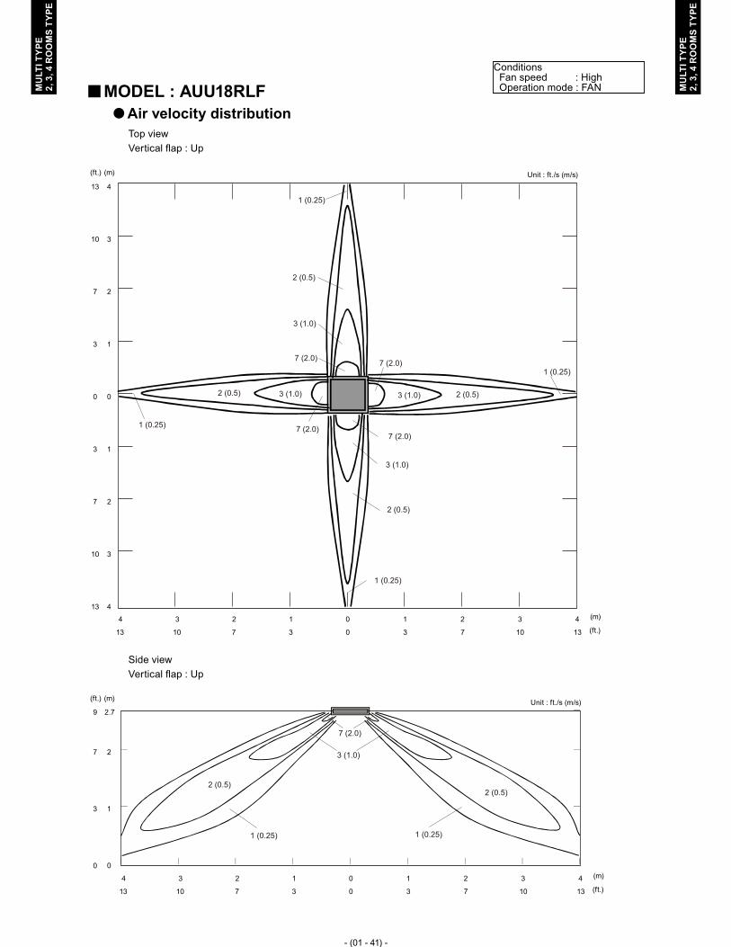
- (01 - 41) -
MU
LTI T
YPE
2, 3
, 4 R
OO
MS
TYPE
MU
LTI T
YPE
2, 3
, 4 R
OO
MS
TYPE
MODEL : AUU18RLF �Air velocity distribution �Top viewVertical flap : Up
7 (2.0)7 (2.0)
7 (2.0)7 (2.0)
3 (1.0)
3 (1.0)
3 (1.0)
3 (1.0)
2 (0.5)
2 (0.5)
2 (0.5)
2 (0.5)
1 (0.25)
1 (0.25)
1 (0.25)
1 (0.25)
Unit : ft./s (m/s)(m)(ft.)
00
3
3
7
7
10
10
13
13
1
1
2
2
3
3
4
4(m)
(ft.)0
0
11
33 77 1010 1313
22 33 44
Side viewVertical flap : Up
7 (2.0)
3 (1.0)
2 (0.5)2 (0.5)
1 (0.25) 1 (0.25)
Unit : ft./s (m/s)(m)(ft.)
00
3
7
9
1
2
2.7
(m)
(ft.)0
0
11
33 77 1010 1313
22 33 44
Conditions Fan speed : High Operation mode : FAN

- (01 - 42) -
MU
LTI T
YPE
2, 3
, 4 R
OO
MS
TYPE
MU
LTI T
YPE
2, 3
, 4 R
OO
MS
TYPE
Air velocity distribution �
Side viewVertical flap : Down
5 (1.5) 5 (1.5)
3 (1.0) 3 (1.0)
2 (0.5) 2 (0.5)
1 (0.25) 1 (0.25)
7 (2.0) 7 (2.0)
Unit : ft./s (m/s)(m)(ft.)
00
3
7
9
8
1
2
2.7
2.5
(m)
(ft.)0
0
11
33 77 1010 1313
22 33 44
Air temperature distribution �
Side viewVertical flap : Down
86 (30) 86 (30)
82 (28) 82 (28)
79 (26) 79 (26)
75 (24) 75 (24)
72 (22) 72 (22)
Unit : °F (°C)(m)(ft.)
00
3
7
9
8
1
2
2.7
2.5
(m)
(ft.)0
0
11
33 77 1010 1313
22 33 44
Note: Reference dataConditions Fan speed : High Operation mode : Heating Vertical flap: Downward (4Way)

- (01 - 43) -
MU
LTI T
YPE
2, 3
, 4 R
OO
MS
TYPE
MU
LTI T
YPE
2, 3
, 4 R
OO
MS
TYPE
Conditions Fan speed : High Operation mode : Fan
COMPACT WALL MOUNTED TYPE6-2. MODEL : AS � U7RLF
Side viewVertical flap : DownHorizontal flap : Center
Side viewVertical flap : UpHorizontal flap : Center
Top viewVertical flap : UpHorizontal flap : Right & Left
Top viewVertical flap : UpHorizontal flap : Center
Unit : ft./s (m/s)(m)(ft.)
00
3
3
7
7
1
1
2
2
(m)(ft.)
00
3
3
7
10
7
10
1
1
2
3
2
3
(m)(ft.)
00
3
7
10
1
2
3
(m)(ft.)
00
3
7
10
1
2
3
(m)
(ft.)0
0
1
3 7 10 13 16 20 23 26
2 3 4 5 6 7 8
(m)
(ft.)0
0
1
3 7 10 13 16 20 23 26
2 3 4 5 6 7 8
(m)
(ft.)0
0
1
3 7 10 13 16 20 23 26
2 3 4 5 6 7 8
(m)
(ft.)0
0
1
3 7 10 13 16 20 23 26
2 3 4 5 6 7 8
7 (2.0) 3 (1.0) 2 (0.5)
7 (2.0)
7 (2.0)
3 (1.0)
3 (1.0)
2 (0.5)
2 (0.5)
7 (2.0)
3 (1.0)
2 (0.5)
7 (2.0)
3 (1.0)
2 (0.5)

- (01 - 44) -
MU
LTI T
YPE
2, 3
, 4 R
OO
MS
TYPE
MU
LTI T
YPE
2, 3
, 4 R
OO
MS
TYPE
Conditions Fan speed : High Operation mode : FanMODEL : AS � U9RLF
Side viewVertical flap : DownHorizontal flap : Center
Side viewVertical flap : UpHorizontal flap : Center
Top viewVertical flap : UpHorizontal flap : Right & Left
Top viewVertical flap : UpHorizontal flap : Center
Unit : ft./s (m/s)(m)(ft.)
00
3
3
7
7
1
1
2
2
(m)(ft.)
00
3
3
7
10
7
10
1
1
2
3
2
3
(m)(ft.)
00
3
7
10
1
2
3
(m)(ft.)
00
3
7
10
1
2
3
(m)
(ft.)0
0
1
3 7 10 13 16 20 23 26
2 3 4 5 6 7 8
(m)
(ft.)0
0
1
3 7 10 13 16 20 23 26
2 3 4 5 6 7 8
(m)
(ft.)0
0
1
3 7 10 13 16 20 23 26
2 3 4 5 6 7 8
(m)
(ft.)0
0
1
3 7 10 13 16 20 23 26
2 3 4 5 6 7 8
7 (2.0) 3 (1.0) 2 (0.5)
7 (2.0)
7 (2.0)
3 (1.0)
3 (1.0)
2 (0.5)
2 (0.5)
3 (1.0)
2 (0.5)7 (2.0)
7 (2.0)
3 (1.0)
2 (0.5)

- (01 - 45) -
MU
LTI T
YPE
2, 3
, 4 R
OO
MS
TYPE
MU
LTI T
YPE
2, 3
, 4 R
OO
MS
TYPE
Conditions Fan speed : High Operation mode : Fan
MODEL : AS � U12RLF
Side viewVertical flap : DownHorizontal flap : Center
Side viewVertical flap : UpHorizontal flap : Center
Top viewVertical flap : UpHorizontal flap : Right & Left
Top viewVertical flap : UpHorizontal flap : Center
Unit : ft./s (m/s)(m)(ft.)
00
3
3
7
7
1
1
2
2
(m)(ft.)
00
3
3
7
10
7
10
1
1
2
3
2
3
(m)(ft.)
00
3
7
10
1
2
3
(m)(ft.)
00
3
7
10
1
2
3
(m)
(ft.)0
0
1
3 7 10 13 16 20 23 26
2 3 4 5 6 7 8
(m)
(ft.)0
0
1
3 7 10 13 16 20 23 26
2 3 4 5 6 7 8
(m)
(ft.)0
0
1
3 7 10 13 16 20 23 26
2 3 4 5 6 7 8
(m)
(ft.)0
0
1
3 7 10 13 16 20 23 26
2 3 4 5 6 7 8
7 (2.0) 3 (1.0) 2 (0.5)
7 (2.0)
7 (2.0)
3 (1.0)
3 (1.0)
2 (0.5)
2 (0.5)
3 (1.0)2 (0.5)7 (2.0)
7 (2.0)
3 (1.0)
2 (0.5)

- (01 - 46) -
MU
LTI T
YPE
2, 3
, 4 R
OO
MS
TYPE
MU
LTI T
YPE
2, 3
, 4 R
OO
MS
TYPE
Conditions Fan speed : High Operation mode : Fan
WALL MOUNTED TYPE6-3. MODEL : ASU18RLF �
Top viewVertical flap : UpHorizontal flap : Center
Top viewVertical flap : UpHorizontal flap : Right & Left
Side viewVertical flap : UpHorizontal flap : Center
Side viewVertical flap : DownHorizontal flap : Center
7 (2.0) 3 (1.0) 2 (0.5)
7 (2.0)3 (1.0)
2 (0.5)
7 (2.0)
3 (1.0)
2 (0.5)
7 (2.0)
7 (2.0)
3 (1.0)
3 (1.0)
2 (0.5)
2 (0.5)
Unit : ft./s (m/s)
Unit : ft./s (m/s)
Unit : ft./s (m/s)
Unit : ft./s (m/s)
(m)(ft.)
00
3
3
7
7
1
1
2
2
(m)
(ft.)0
0
1
3 7 10 13 16 20 23 26
2 3 4 5 6 7 8
(m)
(ft.)0
0
1
3 7 10 13 16 20 23 26
2 3 4 5 6 7 8
(m)
(ft.)0
0
1
3 7 10 13 16 20 23 26
2 3 4 5 6 7 8
(m)
(ft.)0
0
1
3 7 10 13 16 20 23 26
2 3 4 5 6 7 8
(m)(ft.)
00
3
3
7
7
1
1
2
2
3
3
10
10
(m)(ft.)
00
3
7
10
1
2
3
(m)(ft.)
00
3
7
10
1
2
3

- (01 - 47) -
MU
LTI T
YPE
2, 3
, 4 R
OO
MS
TYPE
MU
LTI T
YPE
2, 3
, 4 R
OO
MS
TYPE
Conditions Fan speed : High Operation mode : Fan
MODEL : ASU24RLF �
Top viewVertical flap : UpHorizontal flap : Center
Top viewVertical flap : UpHorizontal flap : Right & Left
Side viewVertical flap : UpHorizontal flap : Center
Side viewVertical flap : DownHorizontal flap : Center
7 (2.0) 3 (1.0) 2 (0.5)
7 (2.0)
7 (2.0)
3 (1.0)
3 (1.0)
2 (0.5)
2 (0.5)
7 (2.0)3 (1.0) 2 (0.5)
7 (2.0)
3 (1.0)
2 (0.5)
Unit : ft./s (m/s)(m)(ft.)
00
3
3
7
7
1
1
2
2
(m)
(ft.)0
0
1
3 7 10 13 16 20 23 26
2 3 4 5 6 7 8
Unit : ft./s (m/s)
(m)
(ft.)0
0
1
3 7 10 13 16 20 23 26
2 3 4 5 6 7 8
(m)(ft.)
00
3
3
7
7
1
1
2
2
3
3
10
10
Unit : ft./s (m/s)
(m)
(ft.)0
0
1
3 7 10 13 16 20 23 26
2 3 4 5 6 7 8
(m)(ft.)
00
3
7
10
1
2
3
Unit : ft./s (m/s)
(m)
(ft.)0
0
1
3 7 10 13 16 20 23 26
2 3 4 5 6 7 8
(m)(ft.)
00
3
7
10
1
2
3

- (01 - 48) -
MU
LTI T
YPE
2, 3
, 4 R
OO
MS
TYPE
MU
LTI T
YPE
2, 3
, 4 R
OO
MS
TYPE
FAN PERFORMANCE CURVE7. SLIM DUCT TYPE7-1.
MODEL : ARU9RLF �
SP mode09 upper limit
Normal SP upper limit
SP mode00 upper limit
SP mode09 lower limit
Hi (SP mode09)
Hi (Normal SP)
Hi (SP mode00)
Quiet (Normal SP)
Quiet (SP mode00)
Quiet (SP mode09)
0.24 (60)
0.40 (100)
0.20 (50)
0.36 (90)
0.16 (40)
0.32 (80)
0.08 (20)
0.04 (10)
0.12 (30)
0.28 (70)
0 (0)
0.44 (110)E
xter
nal S
tatic
Pre
ssur
e [in
.WG
(Pa)
]
(700)(600)(300) (400) (500) (800)412353177 235 294 471
Air Flow [CFM (m3/h)]
Hi (Normal SP)
Available air flow rate range (High level)
Hi (SP mode03)
Hi (SP mode04)Hi (SP mode00)
Hi (SP mode05)Hi (SP mode01)
Hi (SP mode06)
Hi (SP mode02)
Hi (SP mode07)
Hi (SP mode08)
Hi (SP mode09)
(700)(600)(300) (400) (500) (800)412353177 235 294 471
Air Flow [CFM (m3/h)]
0.24 (60)
0.40 (100)
0.20 (50)
0.36 (90)
0.16 (40)
0.32 (80)
0.08 (20)
0.04 (10)
0.12 (30)
0.28 (70)
0 (0)
0.44 (110)
Ext
erna
l Sta
tic P
ress
ure
[in.W
G (P
a)]

- (01 - 49) -
MU
LTI T
YPE
2, 3
, 4 R
OO
MS
TYPE
MU
LTI T
YPE
2, 3
, 4 R
OO
MS
TYPE
Cooling �
(700)412
(600)353
(400)235
(500)294
(800)471
Air Flow [CFM (m3/h)]
100
120
80
60
40
20
0
Cap
acity
(%)
Capacity
Heating �
100
120
80
60
40
20
0
Cap
acity
(%)
Capacity
(700)412
(600)353
(500)294
(800)471
Air Flow [CFM (m3/h)](400)235

- (01 - 50) -
MU
LTI T
YPE
2, 3
, 4 R
OO
MS
TYPE
MU
LTI T
YPE
2, 3
, 4 R
OO
MS
TYPE
MODEL : ARU12RLF �
SP mode09 upper limit
Normal SP upper limit
SP mode00 upper limit
SP mode09 lower limit
Hi (SP mode09)
Hi (Normal SP)
Hi (SP mode00)
Quiet (Normal SP)
Quiet (SP mode00)
Quiet (SP mode09)
(700)(600)(300) (400) (500) (800)412353177 235 294 471
Air Flow [CFM (m3/h)]
0.24 (60)
0.40 (100)
0.20 (50)
0.36 (90)
0.16 (40)
0.32 (80)
0.08 (20)
0.04 (10)
0.12 (30)
0.28 (70)
0 (0)
0.44 (110)E
xter
nal S
tatic
Pre
ssur
e [in
.WG
(Pa)
]
Hi (Normal SP)
Available air flow rate range (High level)
Hi (SP mode03)
Hi (SP mode04)Hi (SP mode00)
Hi (SP mode05)Hi (SP mode01)
Hi (SP mode06)Hi (SP mode02)
Hi (SP mode07)
Hi (SP mode08)
Hi (SP mode09)
(700)(600)(300) (400) (500) (800)412353177 235 294 471
Air Flow [CFM (m3/h)]
0.24 (60)
0.40 (100)
0.20 (50)
0.36 (90)
0.16 (40)
0.32 (80)
0.08 (20)
0.04 (10)
0.12 (30)
0.28 (70)
0 (0)
0.44 (110)
Ext
erna
l Sta
tic P
ress
ure
[in.W
G (P
a)]

- (01 - 51) -
MU
LTI T
YPE
2, 3
, 4 R
OO
MS
TYPE
MU
LTI T
YPE
2, 3
, 4 R
OO
MS
TYPE
Cooling �
100
120
80
60
40
20
0
Cap
acity
(%)
Capacity
(700)412
(600)353
(900)530
(800)471
Air Flow [CFM (m3/h)](500)294
Heating �
100
120
80
60
40
20
0
Cap
acity
(%)
Capacity
(700)412
(600)353
(900)530
(800)471
Air Flow [CFM (m3/h)](500)294

- (01 - 52) -
MU
LTI T
YPE
2, 3
, 4 R
OO
MS
TYPE
MU
LTI T
YPE
2, 3
, 4 R
OO
MS
TYPE
MODEL : ARU18RLF �
SP mode09 upper limit
Normal SP upper limit
SP mode00 upper limit
SP mode09 lower limit
Hi (SP mode09)
Hi (Normal SP)
Hi (SP mode00)
Quiet (Normal SP)
Quiet (SP mode00)
Quiet (SP mode09)
(700)(600) (800) (900) (1000) (1100) (1200)Air Flow [CFM (m3/h)]
412353 471 530 589 647 706
0.24 (60)
0.40 (100)
0.20 (50)
0.36 (90)
0.16 (40)
0.32 (80)
0.08 (20)
0.04 (10)
0.12 (30)
0.28 (70)
0 (0)
0.44 (110)
Ext
erna
l Sta
tic P
ress
ure
[in.W
G (P
a)]
Hi (Normal SP)
Available air flow rate range (High level)
Hi (SP mode03)
Hi (SP mode04)Hi (SP mode00)
Hi (SP mode05)Hi (SP mode01)
Hi (SP mode06)Hi (SP mode02)
Hi (SP mode07)
Hi (SP mode08)
Hi (SP mode09)
(700)(600) (800) (900) (1000) (1100) (1200)Air Flow [CFM (m3/h)]
412353 471 530 589 647 706
0.24 (60)
0.40 (100)
0.20 (50)
0.36 (90)
0.16 (40)
0.32 (80)
0.08 (20)
0.04 (10)
0.12 (30)
0.28 (70)
0 (0)
0.44 (110)
Ext
erna
l Sta
tic P
ress
ure
[in.W
G (P
a)]

- (01 - 53) -
MU
LTI T
YPE
2, 3
, 4 R
OO
MS
TYPE
MU
LTI T
YPE
2, 3
, 4 R
OO
MS
TYPE
Cooling �
100
120
80
60
40
20
0
Cap
acity
(%)
Capacity
Air Flow [CFM (m3/h)](700)412
(800)471
(900)530
(1000)589
(1100)647
Heating �
100
120
80
60
40
20
0
Cap
acity
(%)
Capacity
Air Flow [CFM (m3/h)](700)412
(800)471
(900)530
(1000)589
(1100)647

- (01 - 54) -
MU
LTI T
YPE
2, 3
, 4 R
OO
MS
TYPE
MU
LTI T
YPE
2, 3
, 4 R
OO
MS
TYPE
MODEL : ARU24RLF �
0.24 (60)
0.20 (50)
0.16 (40)
0.32 (80)
0.08 (20)
0.04 (10)
0.12 (30)
0.28 (70)
0 (0)
Ext
erna
l Sta
tic P
ress
ure
[in.W
G (P
a)]
SP mode05 upper limit
Normal SP upper limit
SP mode00 upper limit SP mode05
lower limit
Hi (SP mode05)
Hi (Normal SP)
Hi (SP mode00)
Quiet (Normal SP)
Quiet (SP mode00)
Quiet (SP mode05)
(800) (900) (1000) (1100) (1200) (1300) (1400) (1500) (1600)Air Flow [CFM (m3/h)]
471 530 589 647 706 765 824 883 942
0.24 (60)
0.20 (50)
0.16 (40)
0.32 (80)
0.08 (20)
0.04 (10)
0.12 (30)
0.28 (70)
0 (0)
Ext
erna
l Sta
tic P
ress
ure
[in.W
G (P
a)]
Hi (Normal SP)
Available air flow rate range (High level)
Hi (SP mode03)
Hi (SP mode04)
Hi (SP mode00)
Hi (SP mode05)
Hi (SP mode01)
Hi (SP mode02)
(800) (900) (1000) (1100) (1200) (1300) (1400) (1500) (1600)Air Flow [CFM (m3/h)]
471 530 589 647 706 765 824 883 942

- (01 - 55) -
MU
LTI T
YPE
2, 3
, 4 R
OO
MS
TYPE
MU
LTI T
YPE
2, 3
, 4 R
OO
MS
TYPE
Cooling �
(800) (900) (1000) (1100) (1200) (1300) (1400) (1500) (1600)Air Flow [CFM (m3/h)]
471 530 589 647 706 765 824 883 942
100
120
80
60
40
20
0
Cap
acity
(%)
Capacity
Heating �
(800) (900) (1000) (1100) (1200) (1300) (1400) (1500) (1600)Air Flow [CFM (m3/h)]
471 530 589 647 706 765 824 883 942
100
120
80
60
40
20
0
Cap
acity
(%)
Capacity

- (01 - 56) -
MU
LTI T
YPE
2, 3
, 4 R
OO
MS
TYPE
MU
LTI T
YPE
2, 3
, 4 R
OO
MS
TYPE
AIR FLOW8.
Type Model Operation mode
Fan speed
Air flowm3/h l/s CFM
Compact Cassette
AUU9RLF
Cooling
High 540 150 318Med 490 136 288Low 440 122 259
Quiet 390 108 230
Heating
High 540 150 318Med 490 136 288Low 440 122 259
Quiet 390 108 230
AUU12RLF
Cooling
High 610 169 359Med 530 147 312Low 470 131 277
Quiet 410 114 241
Heating
High 610 169 359Med 530 147 312Low 470 131 277
Quiet 410 114 241
AUU18RLF
Cooling
High 750 208 441Med 610 169 359Low 520 144 306
Quiet 410 114 241
Heating
High 800 222 471Med 710 197 418Low 600 167 353
Quiet 450 125 265
Slim Duct
ARU9RLF
Cooling
High 600 167 353Med 530 147 312Low 440 122 259
Quiet 380 106 224
Heating
High 600 167 353Med 530 147 312Low 440 122 259
Quiet 380 106 224
ARU12RLF
Cooling
High 600 167 353Med 530 147 312Low 440 122 259
Quiet 380 106 224
Heating
High 600 167 353Med 530 147 312Low 440 122 259
Quiet 380 106 224
ARU18RLF
Cooling
High 930 258 547Med 860 239 506Low 790 219 465
Quiet 640 178 377
Heating
High 930 258 547Med 860 239 506Low 790 219 465
Quiet 640 178 377
ARU24RLF
Cooling
High 1330 369 783Med 1180 328 695Low 990 275 583
Quiet 700 194 412
Heating
High 1330 369 783Med 1180 328 695Low 990 275 583
Quiet 700 194 412
Conversion Factor1 m3/h = 0.2778 l/s = 0.5886 CFM3.6 m3/h = 1 l/s1.699 m3/h = 1 CFM

- (01 - 57) -
MU
LTI T
YPE
2, 3
, 4 R
OO
MS
TYPE
MU
LTI T
YPE
2, 3
, 4 R
OO
MS
TYPE
Type Model Operation mode
Fan speed
Air flowm3/h l/s CFM
Compact Wall
Mounted
ASU7RLF
Cooling
High 560 156 330Med 500 139 294Low 430 119 253
Quiet 340 94 200
Heating
High 560 156 330Med 500 139 294Low 430 119 253
Quiet 350 97 206
ASU9RLF
Cooling
High 600 167 353Med 520 144 306Low 430 119 253
Quiet 340 94 200
Heating
High 600 167 353Med 520 144 306Low 430 119 253
Quiet 350 97 206
ASU12RLF
Cooling
High 660 183 388Med 560 156 330Low 450 125 265
Quiet 340 94 200
Heating
High 660 183 388Med 560 156 330Low 470 131 277
Quiet 350 97 206
Wall Mounted
ASU18RLF
Cooling
High 920 256 542Med 740 206 436Low 620 172 365
Quiet 550 153 324
Heating
High 920 256 542Med 740 206 436Low 620 172 365
Quiet 550 153 324
ASU24RLF
Cooling
High 1120 311 659Med 900 250 530Low 740 206 436
Quiet 620 172 365
Heating
High 1100 306 647Med 900 250 530Low 740 206 436
Quiet 620 172 365
Conversion Factor1 m3/h = 0.2778 l/s = 0.5886 CFM3.6 m3/h = 1 l/s1.699 m3/h = 1 CFM

- (01 - 58) -
MU
LTI T
YPE
2, 3
, 4 R
OO
MS
TYPE
MU
LTI T
YPE
2, 3
, 4 R
OO
MS
TYPE
NOISE LEVEL CURVE9. COMPACT CASSETTE TYPE9-1.
MODEL : AUU9RLF �Cooling � �Heating
MODEL : AUU12RLF �Cooling � �Heating
0
10
20
30
40
50
60
70
80
63 125 250 500 1,000 2,000 4,000 8,000
NC-20
NC-40
NC-50
NC-60
NC-30
NC-15
NC-25
NC-35
NC-45
NC-55
NC-65
High
Quiet
0
10
20
30
40
50
60
70
80
63 125 250 500 1,000 2,000 4,000 8,000
NC-20
NC-40
NC-50
NC-60
NC-30
NC-15
NC-25
NC-35
NC-45
NC-55
NC-65
High
Quiet
0
10
20
30
40
50
60
70
80
63 125 250 500 1,000 2,000 4,000 8,000
NC-20
NC-40
NC-50
NC-60
NC-30
NC-15
NC-25
NC-35
NC-45
NC-55
NC-65
High
Quiet
0
10
20
30
40
50
60
70
80
63 125 250 500 1,000 2,000 4,000 8,000
NC-20
NC-40
NC-50
NC-60
NC-30
NC-15
NC-25
NC-35
NC-45
NC-55
NC-65
High
Quiet
Oct
ave
band
sou
nd p
ress
ure
leve
l, dB
:(0dB
=0.0
002μ
bar)
Octave band center frequency, Hz
Oct
ave
band
sou
nd p
ress
ure
leve
l, dB
:(0dB
=0.0
002μ
bar)
Octave band center frequency, Hz
Oct
ave
band
sou
nd p
ress
ure
leve
l, dB
:(0dB
=0.0
002μ
bar)
Octave band center frequency, Hz
Oct
ave
band
sou
nd p
ress
ure
leve
l, dB
:(0dB
=0.0
002μ
bar)
Octave band center frequency, Hz

- (01 - 59) -
MU
LTI T
YPE
2, 3
, 4 R
OO
MS
TYPE
MU
LTI T
YPE
2, 3
, 4 R
OO
MS
TYPE
MODEL : AUU18RLF �Cooling � �Heating
0
10
20
30
40
50
60
70
80
63 125 250 500 1,000 2,000 4,000 8,000
NC-20
NC-40
NC-50
NC-60
NC-30
NC-15
NC-25
NC-35
NC-45
NC-55
NC-65
High
Quiet
0
10
20
30
40
50
60
70
80
63 125 250 500 1,000 2,000 4,000 8,000
NC-20
NC-40
NC-50
NC-60
NC-30
NC-15
NC-25
NC-35
NC-45
NC-55
NC-65
High
Quiet
Oct
ave
band
sou
nd p
ress
ure
leve
l, dB
:(0dB
=0.0
002μ
bar)
Octave band center frequency, Hz
Oct
ave
band
sou
nd p
ress
ure
leve
l, dB
:(0dB
=0.0
002μ
bar)
Octave band center frequency, Hz
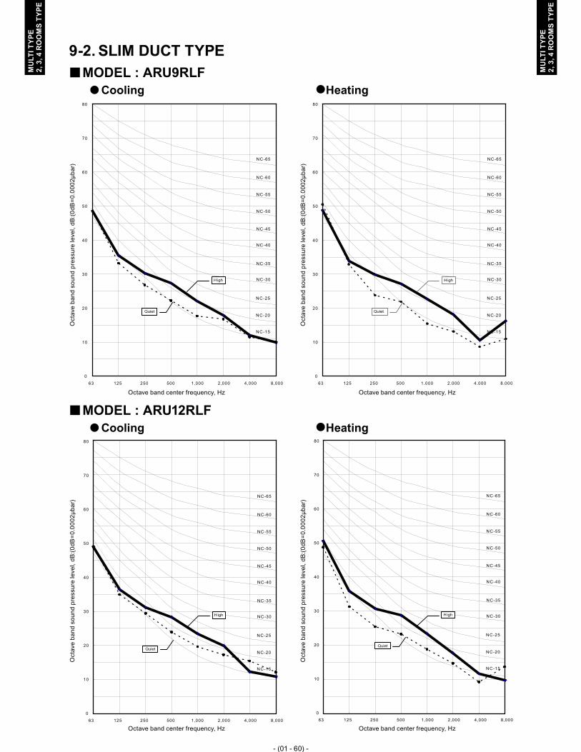
- (01 - 60) -
MU
LTI T
YPE
2, 3
, 4 R
OO
MS
TYPE
MU
LTI T
YPE
2, 3
, 4 R
OO
MS
TYPE
SLIM DUCT TYPE9-2. MODEL : ARU9RLF �
Cooling � �Heating
MODEL : ARU12RLF �Cooling � �Heating
0
10
20
30
40
50
60
70
80
63 125 250 500 1,000 2,000 4,000 8,000
NC-20
NC-40
NC-50
NC-60
NC-30
NC-15
NC-25
NC-35
NC-45
NC-55
NC-65
High
Quiet
0
10
20
30
40
50
60
70
80
63 125 250 500 1,000 2,000 4,000 8,000
NC-20
NC-40
NC-50
NC-60
NC-30
NC-15
NC-25
NC-35
NC-45
NC-55
NC-65
High
Quiet
0
10
20
30
40
50
60
70
80
63 125 250 500 1,000 2,000 4,000 8,000
NC-20
NC-40
NC-50
NC-60
NC-30
NC-15
NC-25
NC-35
NC-45
NC-55
NC-65
High
Quiet
0
10
20
30
40
50
60
70
80
63 125 250 500 1,000 2,000 4,000 8,000
NC-20
NC-40
NC-50
NC-60
NC-30
NC-15
NC-25
NC-35
NC-45
NC-55
NC-65
High
Quiet
Oct
ave
band
sou
nd p
ress
ure
leve
l, dB
:(0dB
=0.0
002μ
bar)
Octave band center frequency, Hz
Oct
ave
band
sou
nd p
ress
ure
leve
l, dB
:(0dB
=0.0
002μ
bar)
Octave band center frequency, Hz
Oct
ave
band
sou
nd p
ress
ure
leve
l, dB
:(0dB
=0.0
002μ
bar)
Octave band center frequency, Hz
Oct
ave
band
sou
nd p
ress
ure
leve
l, dB
:(0dB
=0.0
002μ
bar)
Octave band center frequency, Hz

- (01 - 61) -
MU
LTI T
YPE
2, 3
, 4 R
OO
MS
TYPE
MU
LTI T
YPE
2, 3
, 4 R
OO
MS
TYPE
MODEL : ARU18RLF �Cooling � �Heating
MODEL : ARU24RLF �Cooling � �Heating
0
10
20
30
40
50
60
70
80
63 125 250 500 1,000 2,000 4,000 8,000
NC-20
NC-40
NC-50
NC-60
NC-30
NC-15
NC-25
NC-35
NC-45
NC-55
NC-65
High
Quiet
0
10
20
30
40
50
60
70
80
63 125 250 500 1,000 2,000 4,000 8,000
NC-20
NC-40
NC-50
NC-60
NC-30
NC-15
NC-25
NC-35
NC-45
NC-55
NC-65
High
Quiet
0
10
20
30
40
50
60
70
80
63 125 250 500 1,000 2,000 4,000 8,000
NC-20
NC-40
NC-50
NC-60
NC-30
NC-15
NC-25
NC-35
NC-45
NC-55
NC-65
High
Quiet
0
10
20
30
40
50
60
70
80
63 125 250 500 1,000 2,000 4,000 8,000
NC-20
NC-40
NC-50
NC-60
NC-30
NC-15
NC-25
NC-35
NC-45
NC-55
NC-65
High
Quiet
Oct
ave
band
sou
nd p
ress
ure
leve
l, dB
:(0dB
=0.0
002μ
bar)
Octave band center frequency, Hz
Oct
ave
band
sou
nd p
ress
ure
leve
l, dB
:(0dB
=0.0
002μ
bar)
Octave band center frequency, Hz
Oct
ave
band
sou
nd p
ress
ure
leve
l, dB
:(0dB
=0.0
002μ
bar)
Octave band center frequency, Hz
Oct
ave
band
sou
nd p
ress
ure
leve
l, dB
:(0dB
=0.0
002μ
bar)
Octave band center frequency, Hz

- (01 - 62) -
MU
LTI T
YPE
2, 3
, 4 R
OO
MS
TYPE
MU
LTI T
YPE
2, 3
, 4 R
OO
MS
TYPE
COMPACT WALL MOUNTED TYPE9-3. MODEL : AS � U7RLF
Cooling � �Heating
MODEL : AS � U9RLFCooling � �Heating
0
10
20
30
40
50
60
70
80
63 125 250 500 1,000 2,000 4,000 8,000
NC-20
NC-40
NC-50
NC-60
NC-30
NC-15
NC-25
NC-35
NC-45
NC-55
NC-65
High
Quiet
0
10
20
30
40
50
60
70
80
63 125 250 500 1,000 2,000 4,000 8,000
NC-20
NC-40
NC-50
NC-60
NC-30
NC-15
NC-25
NC-35
NC-45
NC-55
NC-65
High
Quiet
0
10
20
30
40
50
60
70
80
63 125 250 500 1,000 2,000 4,000 8,000
NC-20
NC-40
NC-50
NC-60
NC-30
NC-15
NC-25
NC-35
NC-45
NC-55
NC-65
High
Quiet
0
10
20
30
40
50
60
70
80
63 125 250 500 1,000 2,000 4,000 8,000
NC-20
NC-40
NC-50
NC-60
NC-30
NC-15
NC-25
NC-35
NC-45
NC-55
NC-65
High
Quiet
Oct
ave
band
sou
nd p
ress
ure
leve
l, dB
:(0dB
=0.0
002μ
bar)
Octave band center frequency, Hz
Oct
ave
band
sou
nd p
ress
ure
leve
l, dB
:(0dB
=0.0
002μ
bar)
Octave band center frequency, Hz
Oct
ave
band
sou
nd p
ress
ure
leve
l, dB
:(0dB
=0.0
002μ
bar)
Octave band center frequency, Hz
Oct
ave
band
sou
nd p
ress
ure
leve
l, dB
:(0dB
=0.0
002μ
bar)
Octave band center frequency, Hz

- (01 - 63) -
MU
LTI T
YPE
2, 3
, 4 R
OO
MS
TYPE
MU
LTI T
YPE
2, 3
, 4 R
OO
MS
TYPE
MODEL : AS � U12RLFCooling � �Heating
0
10
20
30
40
50
60
70
80
63 125 250 500 1,000 2,000 4,000 8,000
NC-20
NC-40
NC-50
NC-60
NC-30
NC-15
NC-25
NC-35
NC-45
NC-55
NC-65
High
Quiet
0
10
20
30
40
50
60
70
80
63 125 250 500 1,000 2,000 4,000 8,000
NC-20
NC-40
NC-50
NC-60
NC-30
NC-15
NC-25
NC-35
NC-45
NC-55
NC-65
High
Quiet
Oct
ave
band
sou
nd p
ress
ure
leve
l, dB
:(0dB
=0.0
002μ
bar)
Octave band center frequency, Hz
Oct
ave
band
sou
nd p
ress
ure
leve
l, dB
:(0dB
=0.0
002μ
bar)
Octave band center frequency, Hz

- (01 - 64) -
MU
LTI T
YPE
2, 3
, 4 R
OO
MS
TYPE
MU
LTI T
YPE
2, 3
, 4 R
OO
MS
TYPE
WALL MOUNTED TYPE9-4. MODEL : AS � U18RLF
Cooling � �Heating
MODEL : AS � U24RLFCooling � �Heating
0
10
20
30
40
50
60
70
80
63 125 250 500 1,000 2,000 4,000 8,000
NC-20
NC-40
NC-50
NC-60
NC-30
NC-15
NC-25
NC-35
NC-45
NC-55
NC-65
High
Quiet
0
10
20
30
40
50
60
70
80
63 125 250 500 1,000 2,000 4,000 8,000
NC-20
NC-40
NC-50
NC-60
NC-30
NC-15
NC-25
NC-35
NC-45
NC-55
NC-65
High
Quiet
0
10
20
30
40
50
60
70
80
63 125 250 500 1,000 2,000 4,000 8,000
NC-20
NC-40
NC-50
NC-60
NC-30
NC-15
NC-25
NC-35
NC-45
NC-55
NC-65
High
Quiet
0
10
20
30
40
50
60
70
80
63 125 250 500 1,000 2,000 4,000 8,000
NC-20
NC-40
NC-50
NC-60
NC-30
NC-15
NC-25
NC-35
NC-45
NC-55
NC-65
High
Quiet
Oct
ave
band
sou
nd p
ress
ure
leve
l, dB
:(0dB
=0.0
002μ
bar)
Octave band center frequency, Hz
Oct
ave
band
sou
nd p
ress
ure
leve
l, dB
:(0dB
=0.0
002μ
bar)
Octave band center frequency, Hz
Oct
ave
band
sou
nd p
ress
ure
leve
l, dB
:(0dB
=0.0
002μ
bar)
Octave band center frequency, Hz
Oct
ave
band
sou
nd p
ress
ure
leve
l, dB
:(0dB
=0.0
002μ
bar)
Octave band center frequency, Hz

- (01 - 65) -
MU
LTI T
YPE
2, 3
, 4 R
OO
MS
TYPE
MU
LTI T
YPE
2, 3
, 4 R
OO
MS
TYPE
SOUND LEVEL CHECK POINT9-5. COMPACT CASSETTE TYPE �
Microphone
Microphone
4ft.
11-1
/16i
n. (1
.5m
)

- (01 - 66) -
MU
LTI T
YPE
2, 3
, 4 R
OO
MS
TYPE
MU
LTI T
YPE
2, 3
, 4 R
OO
MS
TYPE
SLIM DUCT TYPE �
CenterCenter
Front viewSide view
4ft.
11-1
/16i
n. (1
.5m
)
6ft. 6-3/4in. (2m) 3ft. 3-3/8in. (1m)
Microphone
Measuring duct Measuring duct
Microphone
COMPACT WALL MOUNTED AND WALL MOUNTED TYPE �
3ft. 3-3/8in. (1m)
2ft.
7-1
/2in
. (0.
8m)
Microphone Microphone

- (01 - 67) -
MU
LTI T
YPE
2, 3
, 4 R
OO
MS
TYPE
MU
LTI T
YPE
2, 3
, 4 R
OO
MS
TYPE
ELECTRIC CHARACTERISTICS10. Power Supply Indoor Rated
Type Model name Hz Voltage (V)
MCA (A)
Input Power (W)
FLA (A)
Compact CassetteAUU9RLF 60 208 / 230 0.19 / 0.19 17 / 18 0.15 / 0.15AUU12RLF 60 208 / 230 0.24 / 0.24 22 / 23 0.19 / 0.19AUU18RLF 60 208 / 230 0.41 / 0.38 38 / 39 0.32 / 0.30
Slim Duct
ARU9RLF 60 208 / 230 0.40 / 0.38 47 / 49 0.32 / 0.30ARU12RLF 60 208 / 230 0.47 / 0.44 56 / 58 0.37 / 0.35ARU18RLF 60 208 / 230 0.59 / 0.55 71 / 73 0.47 / 0.44ARU24RLF 60 208 / 230 0.89 / 0.83 109 / 111 0.71 / 0.66
Compact Wall MountedASU7RLF 60 208 / 230 0.18 / 0.17 15 / 15 0.14 / 0.13ASU9RLF 60 208 / 230 0.20 / 0.19 17 / 17 0.16 / 0.15ASU12RLF 60 208 / 230 0.25 / 0.24 22 / 22 0.20 / 0.19
Wall Mounted ASU18RLF 60 208 / 230 0.42 / 0.40 40 / 41 0.34 / 0.32ASU24RLF 60 208 / 230 0.71 / 0.66 68 / 69 0.57 / 0.53
Wiring spec. (Indoor unit to outdoor unit)
Connection cable AWG 14
Limited wiring length [ft. (m)] 85 (26)
MCA : Min Circuit Amps = Max Operating Current (Full Load).MFA : Main Fuse (Circuit breaker) Amps.

- (01 - 68) -
MU
LTI T
YPE
2, 3
, 4 R
OO
MS
TYPE
MU
LTI T
YPE
2, 3
, 4 R
OO
MS
TYPE
SAFETY DEVICES11.
Model and type PCB fuseFan motor
thermal protector
Terminal thermal fuse
Float switch
Compact Cassette
AUU9RLF
250V 3.15A
266 + 63°F - 48°F(130 +17°C -9°C)
― ○AUU12RLF
AUU18RLF
Slim Duct
ARU9RLF
250V 3.15A275 ± 59°F
(135 ± 15°C)― ○ARU12RLF
ARU18RLFARU24RLF
Compact Wall
Mounted
ASU7RLF250V 3.15A
248 ± 59°F
(120 ± 15°C)
216°F OFF
(102°C OFF)―ASU9RLF
ASU12RLF
Wall MountedASU18RLF
250V 3.15A302 ± 59°F
(150 ± 15°C)
216°F OFF
(102°C OFF)―
ASU24RLF

- (01 - 69) -
MU
LTI T
YPE
2, 3
, 4 R
OO
MS
TYPE
MU
LTI T
YPE
2, 3
, 4 R
OO
MS
TYPE
EXTERNAL INPUT & OUTPUT12.
Indoor unit typeEXTERNAL INPUT EXTERNAL OUTPUT
Control input Operation status output
Fresh air control output Auxiliary heater output
Compact Cassette ● ● ● -
Slim Duct ● ● ● ●
Compact Wall Mounted ● ● - -
Wall Mounted ● ● - -
EXTERNAL INPUT12-1. CONTROL INPUT (Operation/Stop or Forced stop) �
Compact Cassette Slim Duct Comapct Wall Mounted Wall MountedConnector CN102 CN102 CN303 CN14
The air conditioner can be remotely operated by means of the following on-site work."Operation/Stop" mode or "Forced stop" mode can be selected with function setting of indoor unit.Operation is started at the following contents by adding the contact input of a commercial ON/OFF switch to a connector on the external control PC board and turning it ON.
Initial starting after power turned on Starting other than at the leftOperation mode Auto changeover Mode at previous operationSet temperature 76°F (24°C) Temperature at previous operationAir flow mode AUTO Mode at previous operation
Up-down air direction (swing) Standard air direction (swing OFF) Air direction at previous operationLeft-right air direction (swing) Standard air direction (swing OFF) Air direction at previous operation
Circuit diagram example �Indoor unit control PC board *1
Connector
1
3
Signal
Field supply
33ft. (10m) *2
Connected unit
Ex.) Switch
Contact capacity : 24VDC or more, 10mA or more.
*1: PC board of Communication kit is used for Compact wall mounted type.*2: Make the distance from the PC board to the connected unit within 33ft. (10m).
Indoor unit type 1 Pin
(Polarity)3 Pin
(Polarity)Compact Cassette - +
Slim Duct - +Compact Wall Mounted + -
Wall Mounted - +
When function setting is "Operation/Stop" mode ●
Operation
Stop
ON
OFFInput signal
Indoor unit
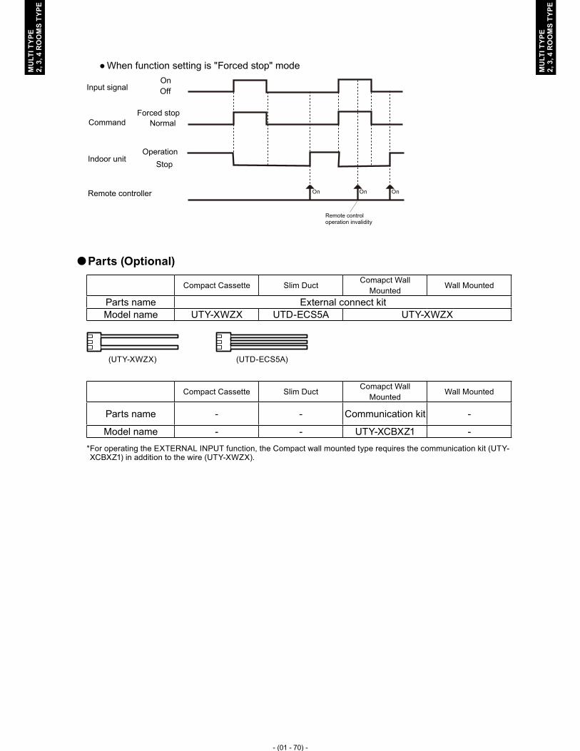
- (01 - 70) -
MU
LTI T
YPE
2, 3
, 4 R
OO
MS
TYPE
MU
LTI T
YPE
2, 3
, 4 R
OO
MS
TYPE
When function setting is "Forced stop" mode ●
Remote controller On On On
Input signalOnOff
Indoor unitOperation
Stop
CommandForced stop
Normal
Remote control operation invalidity
Parts (Optional) �
Compact Cassette Slim DuctComapct Wall
MountedWall Mounted
Parts name External connect kitModel name UTY-XWZX UTD-ECS5A UTY-XWZX
Compact Cassette Slim DuctComapct Wall
MountedWall Mounted
Parts name - - Communication kit -
Model name - - UTY-XCBXZ1 -* For operating the EXTERNAL INPUT function, the Compact wall mounted type requires the communication kit (UTY-XCBXZ1) in addition to the wire (UTY-XWZX).
(UTD-ECS5A)(UTY-XWZX)

- (01 - 71) -
MU
LTI T
YPE
2, 3
, 4 R
OO
MS
TYPE
MU
LTI T
YPE
2, 3
, 4 R
OO
MS
TYPE
Caution �Compact wall mounted type and the other indoor unit type (Compact cassette type, Slim duct type, and Wall mounted type) Do not connect the input terminal together.Connect pin of the same number because there is a polarity in connector.●Example 1 (OK) ●Example 2 (OK)
Connector
1
3
Connector
1
3
Compact cassette
Slim duct
Connector
1
3
Connector
1
3
Compact wall mounted
Compact wall mounted
●Example 3 (Not good)
Connector
1
3
Connector
1
3
Compact wall mounted
Compact cassette
Note the contact capacity when connecting it with two or more indoor units.Secure the contact capacity per one indoor unit of 10mA or more.●Example 4 (OK)
Connector
1
3
Connector
1
3
Compact wall mounted
Compact wall mounted 20mA or more
(10mA x 2)

- (01 - 72) -
MU
LTI T
YPE
2, 3
, 4 R
OO
MS
TYPE
MU
LTI T
YPE
2, 3
, 4 R
OO
MS
TYPE
EXTERNAL OUTPUT12-2. OPERATION STATUS OUTPUT �
Compact Cassette Slim DuctComapct Wall
MountedWall Mounted
Connector CN103 CN103 CN304 CN16
An air conditioner operation status signal can be output.
Circuit diagram example �
Relay spec.:Max.24V DC, 10mA to less than 500mA.
Field supply
Ex.)Display
Indoor unitcontrol PC board *1 Connected unit
Ex.)Relay unit1
2
Signal
Relay power supply
V
Connector
33ft. (10m)*2
24V DC
*1: PC board of Communication kit is used for Compact wall mounted type.*2: Make the distance from the PC board to the connected unit within 33ft. (10m).
ON
OFF
Operation
StopIndoor unit
Output signal
Parts (Optional) �
Compact Cassette Slim Duct Compact Wall Mounted Wall MountedParts name External connect kitModel name UTY-XWZX UTD-ECS5A UTY-XWZX
Compact Cassette Slim DuctCompact Wall
MountedWall Mounted
Parts name - - Communication kit -
Model name - - UTY-XCBXZ1 -* For operating the EXTERNAL OUTPUT function, the Compact wall mounted type requires the communication kit (UTY-XCBXZ1) in addition to the wire (UTY-XWZX).
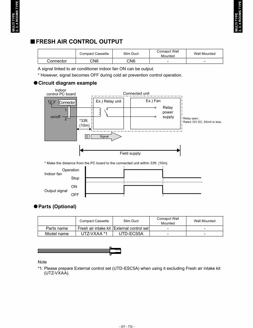
- (01 - 73) -
MU
LTI T
YPE
2, 3
, 4 R
OO
MS
TYPE
MU
LTI T
YPE
2, 3
, 4 R
OO
MS
TYPE
FRESH AIR CONTROL OUTPUT �
Compact Cassette Slim DuctComapct Wall
MountedWall Mounted
Connector CN6 CN6 - -
A signal linked to air conditioner indoor fan ON can be output. * However, signal becomes OFF during cold air prevention control operation.
Circuit diagram example �
Relay spec.:Rated 12V DC, 50mA to less.
Field supply
Indoor control PC board
Connector
1
12 V
on/off 2
Signal
Relay power supply
Ex.) Fan
Connected unit
Ex.) Relay unit
*33ft. (10m)
* Make the distance from the PC board to the connected unit within 33ft. (10m).
ON
OFF
Operation
StopIndoor fan
Output signal
Parts (Optional) �
Compact Cassette Slim DuctComapct Wall
MountedWall Mounted
Parts name Fresh air intake kit External control set - -Model name UTZ-VXAA *1 UTD-ECS5A - -
Note*1: Please prepare External control set (UTD-ESC5A) when using it excluding Fresh air intake kit (UTZ-VXAA).

- (01 - 74) -
MU
LTI T
YPE
2, 3
, 4 R
OO
MS
TYPE
MU
LTI T
YPE
2, 3
, 4 R
OO
MS
TYPE
AUXILIARY HEATER OUTPUT �
Compact Cassette Slim DuctComapct Wall
MountedWall Mounted
Connector - CN10 - -
A signal is outputed from Connector when indoor fan and compressor turn on under heating operation.* Signal output performance specifications are as shown on the right
Ex. When Set Temperature(Ts) is 72°F(22°C) ▪ and Room Temperature(Tr) increase above
52°F(12°C), signal output is on. ▪ and Room Temperature(Tr) increase
above70°F(21°C), signal output is off. ▪ and Room Temperature(Tr) decrease below 66°F(19°C), signal output is on. ▪and Room Temperature(Tr) decrease below 48°F(10°C), signal output is off.
Jumper wire (Indoor Unit) �
This is used to continue indoor unit fan operation for 1 minute after thermo OFF in heating mode.1 minute delay control set by cutting jumper wire on PCB.
Circuit diagram example �
Relay spec.:Rated 12V DC, 50mA to less.
Field supply
Indoor control PC board
Connector
1
12 V
on/off 2
Signal
Relay power supply
Ex.) Heater
Connected unit
Ex.) Relay unit
*33ft.(10m)
* Make the distance from the PC board to the connected unit within 33ft. (10m).
ON
OFF
Operation
StopHeating
operation
Indoor unit fan
ON
OFF
Output signal
1min
CAUTIONPlease locate a external heater between the indoor unit and the outlet.Please be sure to use delay control of a fan.
Parts (Optional) �
Compact Cassette Slim DuctComapct Wall
MountedWall Mounted
Parts name - External control set - -Model name - UTD-ECS5A - -
OFF
OFF
ON
Tr-Ts = -2°F( -1°C)
Tr-Ts
Tr-Ts = -6°F( -3°C)
Tr-Ts = -20°F( -10°C)Tr-Ts = -24°F( -12°C)
ExternalHeater
Supply air Return air
Indoor unit

- (01 - 75) -
MU
LTI T
YPE
2, 3
, 4 R
OO
MS
TYPE
MU
LTI T
YPE
2, 3
, 4 R
OO
MS
TYPE
FUNCTION SETTING13. INDOOR UNIT (setting by jumper wire)13-1.
Note: This function is Slim Duct type only.
SWITCH POSITION �Slim Duct type �
JM1
JM2
JM3
JUMPER WIRE SETTING �Drainage function setting (JM1) �
(�...Factory setting)
JM1 Drainage function
� Connect Valid
Disconnect Invalid
JM2 setting forbidden �
Fan delay setting (JM3) �
(�...Factory setting)
JM3 Fan delay
� Connect Invalid
Disconnect Valid

- (01 - 76) -
MU
LTI T
YPE
2, 3
, 4 R
OO
MS
TYPE
MU
LTI T
YPE
2, 3
, 4 R
OO
MS
TYPE
INDOOR UNIT (setting by wireless remote controller)13-2. The function settings of the control of the indoor unit can be changed by this procedure ●according to the installation conditions. Incorrect settings can cause the indoor unit malfunction.After the power is turned on, perform the “FUNCTION SETTING” according to the ●installation conditions using the remote controller.The settings may be selected between the following two: Function Number or Setting ●Number.Settings will not be changed if invalid numbers or setting numbers are selected. ●
PREPARATION �
(1) Turn on the power to the Outdoor unit.By turning on the power indoor units, so make sure the piping air-tight test and vacuuming have been �
conducted before turning on the power.Also check again to make sure no wiring mistakes were made before turning on the power. �
Indoor units
Outdoor unit
Breaker ON

- (01 - 77) -
MU
LTI T
YPE
2, 3
, 4 R
OO
MS
TYPE
MU
LTI T
YPE
2, 3
, 4 R
OO
MS
TYPE
SWITCHING SELECTION OF FUNCTION SETTING MODE �
(2) Press and hold the “FAN” and the “ SET TEMP. � ” buttons. While holding these 2 buttons, press the "RESET" button.
SET TEMP. ( )RESET
FAN
Function settingmode display
SELECTION AND CONFIRMATION OF SIGNAL CODE �
(3) Press the “ SET TEMP. � ” or “ SET TEMP. � ” buttons to select the custom code that matches the setting with the indoor unit.By selecting the appropriate custom code, the communication between the indoor unit and the wireless RC become possible.
SIGNAL CODE( - - - )
The initial setting is " "
(4) Press the “TIMER MODE" button to send the code to the indoor unit.
Pi Pi
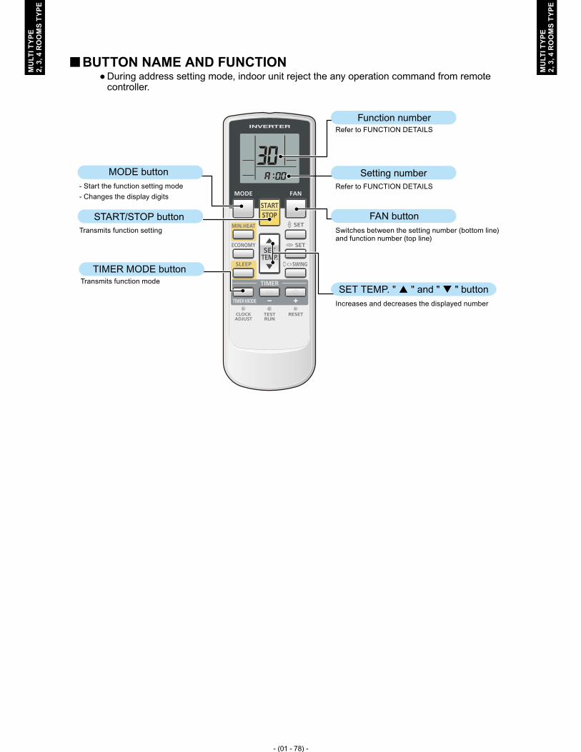
- (01 - 78) -
MU
LTI T
YPE
2, 3
, 4 R
OO
MS
TYPE
MU
LTI T
YPE
2, 3
, 4 R
OO
MS
TYPE
BUTTON NAME AND FUNCTION �During address setting mode, indoor unit reject the any operation command from remote ●controller.
MODE button
START/STOP button
TIMER MODE button
SET TEMP. " � " and " � " button
FAN button
Setting number
Function numberRefer to FUNCTION DETAILS
Refer to FUNCTION DETAILS
Switches between the setting number (bottom line)and function number (top line)
Increases and decreases the displayed number
- Start the function setting mode- Changes the display digits
Transmits function setting
Transmits function mode

- (01 - 79) -
MU
LTI T
YPE
2, 3
, 4 R
OO
MS
TYPE
MU
LTI T
YPE
2, 3
, 4 R
OO
MS
TYPE
FUNCTION SETTING �
(5) Press the “MODE” button to access the function setting mode.
(6) Press the “ � ” or the “ � ” buttons to select the function number. Each time the “MODE” button is pressed, it switches between the one's place and the ten's place positions.
Change digit
(7) Press the FAN button to proceed to setting the number. (Press the FAN button again to return to the function number selection.)
(8) Press the “ � ” or the “ � ” buttons to select the setting number. Each time the “MODE” button is pressed, it switches between the one's place and the ten's place positions.
Change digit
(9) Press the “TIME MODE” button once to send the function mode information.
Pi Pi
(10) Press the “START/STOP” button once to send the function setting information. A beeping noise will be heard if the command is accepted.
*Wrong code: No Response
Pi Pi
Note: Please push "START/STOP" button within 30 seconds after pushing "TIME MODE" button.
FUNCTION DETAILS �Refer to 13-5. FUNCTION DETAILS
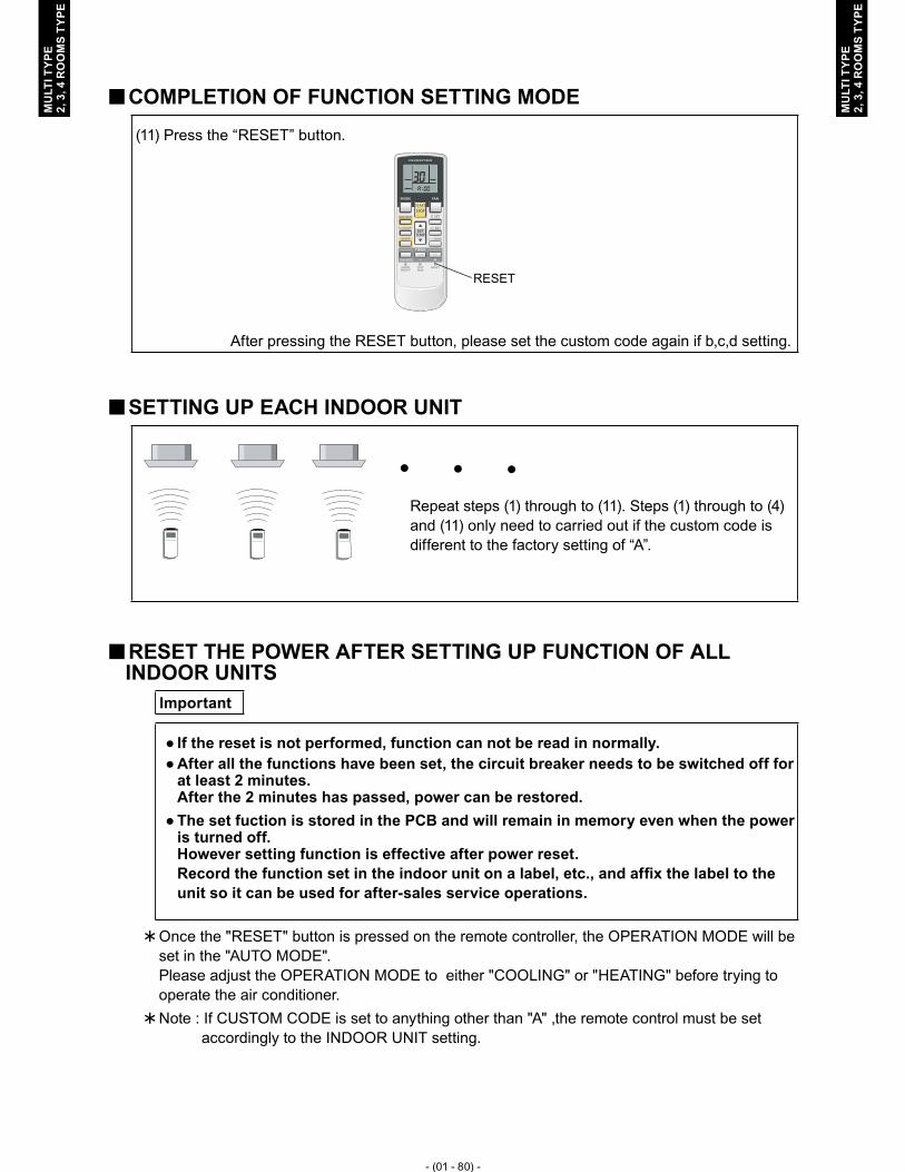
- (01 - 80) -
MU
LTI T
YPE
2, 3
, 4 R
OO
MS
TYPE
MU
LTI T
YPE
2, 3
, 4 R
OO
MS
TYPE
COMPLETION OF FUNCTION SETTING MODE �
(11) Press the “RESET” button.
RESET
After pressing the RESET button, please set the custom code again if b,c,d setting.
SETTING UP EACH INDOOR UNIT �
Repeat steps (1) through to (11). Steps (1) through to (4) and (11) only need to carried out if the custom code is different to the factory setting of “A”.
RESET THE POWER AFTER SETTING UP FUNCTION OF ALL � INDOOR UNITS
Important
If the reset is not performed, function can not be read in normally. ●After all the functions have been set, the circuit breaker needs to be switched off for ●at least 2 minutes. After the 2 minutes has passed, power can be restored.The set fuction is stored in the PCB and will remain in memory even when the power ●is turned off. However setting function is effective after power reset. Record the function set in the indoor unit on a label, etc., and affix the label to the unit so it can be used for after-sales service operations.
Once the "RESET" button is pressed on the remote controller, the OPERATION MODE will be �set in the "AUTO MODE". Please adjust the OPERATION MODE to either "COOLING" or "HEATING" before trying to operate the air conditioner.Note : If CUSTOM CODE is set to anything other than "A" ,the remote control must be set � accordingly to the INDOOR UNIT setting.

- (01 - 81) -
MU
LTI T
YPE
2, 3
, 4 R
OO
MS
TYPE
MU
LTI T
YPE
2, 3
, 4 R
OO
MS
TYPE
REMOTE CONTROLLER SIGNAL CODE SETTING �In function setting, please change to the setting that signal code setting of Wireless remote controller is the same as indoor unit according to the following content when you change signal code setting of indoor unit.
1. Press the START/STOP button until only the clock is displayed on the remote controller display.
2. Press the MODE button for at least five seconds to display the current signal code (initially set to A).
3. Press the SET TEMP. “ � ” or the “ � ” button to change the signal code between A→B→C →D.
4. Press the MODE button again to return to the clock display. The signal code will be changed.
If no buttons are pressed within 30 seconds after the signal code is displayed, the system ●returns to the original clock display. In this case, start again from step 1.The air conditioner signal code is set to A prior to shipment. ●The remote controller resets to signal code A when the batteries in the remote controller ●are replaced. If you use a signal code other than signal code A, reset the signal code after replacing the batteries. If you do not know the air conditioner signal code setting, try each of the signal codes (A→B→C→D) until you find the code which operates the air conditioner.

- (01 - 82) -
MU
LTI T
YPE
2, 3
, 4 R
OO
MS
TYPE
MU
LTI T
YPE
2, 3
, 4 R
OO
MS
TYPE
INDOOR UNIT (setting by wired remote controller)13-3. The function settings of the control of the indoor unit can be changed by this procedure ●according to the installation conditions. Incorrect settings can cause the indoor unit malfunction.After the power is turned on, perform the “FUNCTION SETTING” according to the ●installation conditions using the remote controller.The settings may be selected between the following two: Function Number or Setting ●Number.Settings will not be changed if invalid numbers or setting numbers are selected. ●
PREPARATION �
(1) Turn on the power to the Outdoor unit.By turning on the power indoor units, so make sure the piping air-tight test and vacuuming have been conducted ●before turning on the power.Also check again to make sure no wiring mistakes were made before turning on the power. ●
Indoor units
Outdoor unit
Breaker ON

- (01 - 83) -
MU
LTI T
YPE
2, 3
, 4 R
OO
MS
TYPE
MU
LTI T
YPE
2, 3
, 4 R
OO
MS
TYPE
SWITCHING SELECTION OF FUNCTION SETTING MODE �2) To activate the function setting mode, hold down the three buttons of SET TEMP. V, SET
TEMP. Λ and FAN at the same time for 5 seconds or longer.
Function setting mode initial display
BUTTON NAME AND FUNCTION �During address setting mode, indoor unit reject the any operation command from remote ●controller.
Function numberRefer to FUNCTION DETAILS
Remote controller addressIt fixes to 00.
SET TIME “<” and “>” buttonSwitches the function number.
Setting numberRefer to FUNCTION DETAILS
SET TEMP. “V” and “Λ” button
Switches the setting number.
TIMER SET buttonTransmits function setting

- (01 - 84) -
MU
LTI T
YPE
2, 3
, 4 R
OO
MS
TYPE
MU
LTI T
YPE
2, 3
, 4 R
OO
MS
TYPE
FUNCTION SETTING �3) Pressing the SET TIME < button or the SET TIME > button, to select the function number.
Function number
4) Pressing the SET TEMP. V button or the SET TEMP. Λ button, to select the setting number.
The display flashes during setting number selection.
Ex.) Function number : 30, Setting number : 01
Setting number
5) Pressing the TIMER SET button, confirm the setting. (The data will be transferred to the indoor unit.)
GOODNOT GOOD
When the data was not set up on the indoor ●unit (-- is displayed.)Set up the data again according to the ●procedure in step 5), 6) above.
When the data was normally set up on the indoor unit (Flashing display changes to illuminated display.)
FUNCTION DETAILS �Refer to 13-5. FUNCTION DETAILS

- (01 - 85) -
MU
LTI T
YPE
2, 3
, 4 R
OO
MS
TYPE
MU
LTI T
YPE
2, 3
, 4 R
OO
MS
TYPE
COMPLETION OF FUNCTION SETTING MODE �6) To clear the function setting mode and return to the regular display, hold down the three
buttons of SET TEMP. V, SET TEMP. Λ and FAN at the same time.
Normal mode display
* If no key entry is made for 60 seconds, even though none of the above buttons is pressed, the function setting mode will automatically be cleared. (If the function setting mode is automatically cleared while setting addresses, activate the mode again according to the procedure in step 2) above.)
SETTING UP EACH INDOOR UNIT �Repeat the procedures in steps 1) through 6), and set up the indoor units requiring function setting.
RESET THE POWER AFTER SETTING UP FUNCTION OF ALL �INDOOR UNITS
ImportantIf the reset is not performed, function can not be read in normally. �After all the functions have been set, the circuit breaker needs to be switched off �for at least 2 minutes. After the 2 minutes has passed, power can be restored.The set function is stored in the PCB and will remain in memory even when the �power is turned off. However setting function is effective after power reset. Record the function set in the indoor unit on a label, etc., and affix the label to the unit so it can be used for after-sales service operations.

- (01 - 86) -
MU
LTI T
YPE
2, 3
, 4 R
OO
MS
TYPE
MU
LTI T
YPE
2, 3
, 4 R
OO
MS
TYPE
INDOOR UNIT (setting by simple remote controller)13-4. The function settings of the control of the indoor unit can be changed by this procedure ●according to the installation conditions. Incorrect settings can cause the indoor unit malfunction.After the power is turned on, perform the “FUNCTION SETTING” according to the ●installation conditions using the remote controller.The settings may be selected between the following two: Function Number or Setting ●Number.Settings will not be changed if invalid numbers or setting numbers are selected. ●
PREPARATION �(1) Turn on the power to the Outdoor unit.
By turning on the power indoor units, so make sure the piping air-tight test and vacuuming have been conducted ●before turning on the power.Also check again to make sure no wiring mistakes were made before turning on the power. ●
Indoor units
Outdoor unit
Breaker ON

- (01 - 87) -
MU
LTI T
YPE
2, 3
, 4 R
OO
MS
TYPE
MU
LTI T
YPE
2, 3
, 4 R
OO
MS
TYPE
SWITCHING SELECTION OF FUNCTION SETTING MODE �2) To activate the function setting mode, hold down the three buttons of SET TEMP. �, SET
TEMP. � and FAN at the same time for 5 seconds or longer.
Function setting mode initial display
BUTTON NAME AND FUNCTION �During function setting mode, indoor unit reject the any operation command from remote ●controller.
Function numberRefer to FUNCTION DETAILS
Remote controller addressIt fixes to 00.
FAN buttonEach time this button is pressed, the fan setting changes among “Remote controller address,” “Function number” and “Setting number.”
Setting numberRefer to FUNCTION DETAILS
START/STOP buttonTransmits function setting
SET TEMP. “�” and “�” button
Switches the various numbers.

- (01 - 88) -
MU
LTI T
YPE
2, 3
, 4 R
OO
MS
TYPE
MU
LTI T
YPE
2, 3
, 4 R
OO
MS
TYPE
FUNCTION SETTING �3) Press the FAN button so that the “Function number” display flashes. Then, press either the
SET TEMP. � button or the SET TEMP. � button to set up the function number.
Function number
4) Press the FAN button so that the “Setting number” display flashes. Then, press either the SET TEMP. � button or the SET TEMP. � button to set up the setting number.
Ex.) Function number : 30, Setting number : 01
Setting number
5) Pressing the START/STOP button, confirm the setting. (The data will be transferred to the indoor unit.)
NOT GOOD
When the data was normally set up on the indoor unit.
When the data was not set up on the indoor ●unit (-- is displayed.)Set up the data again according to the ●procedure in step 3), 4) above.
GOOD
FUNCTION DETAILS �Refer to 13-5. FUNCTION DETAILS

- (01 - 89) -
MU
LTI T
YPE
2, 3
, 4 R
OO
MS
TYPE
MU
LTI T
YPE
2, 3
, 4 R
OO
MS
TYPE
COMPLETION OF FUNCTION SETTING MODE �6) Press the three buttons of SET TEMP. �, SET TEMP. � and FAN at the same time for 5
seconds or longer. The function setting mode will be cleared and the regular display will be restored.
Normal mode display
* If no key entry is made for 60 seconds, even though none of the above buttons is pressed, the function setting mode will automatically be cleared. (If the function setting mode is automatically cleared while setting addresses, activate the mode again according to the procedure in step 2) above.)
SETTING UP EACH INDOOR UNIT �Repeat the procedures in steps 1) through 6), and set up the indoor units requiring function setting.
RESET THE POWER AFTER SETTING UP FUNCTION OF ALL �INDOOR UNITS
ImportantIf the reset is not performed, function can not be read in normally. �After all the functions have been set, the circuit breaker needs to be switched off �for at least 2 minutes. After the 2 minutes has passed, power can be restored.The set function is stored in the PCB and will remain in memory even when the �power is turned off. However setting function is effective after power reset. Record the function set in the indoor unit on a label, etc., and affix the label to the unit so it can be used for after-sales service operations.
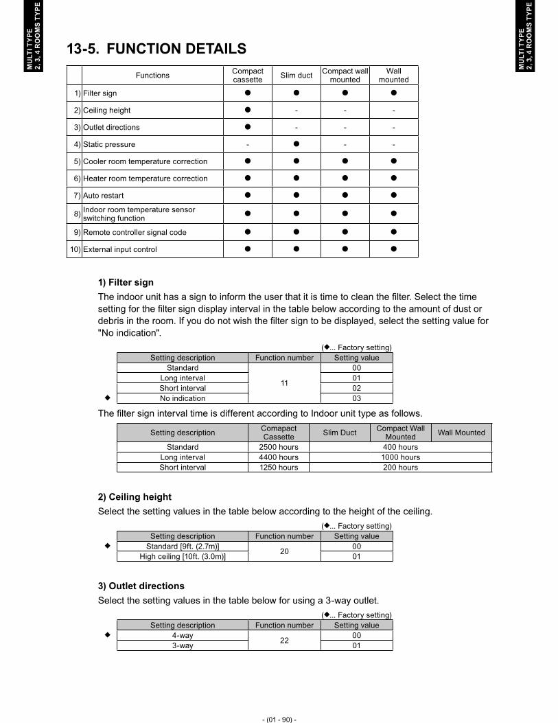
- (01 - 90) -
MU
LTI T
YPE
2, 3
, 4 R
OO
MS
TYPE
MU
LTI T
YPE
2, 3
, 4 R
OO
MS
TYPE
FUNCTION DETAILS13-5. Functions Compact
cassette Slim duct Compact wall mounted
Wall mounted
1) Filter sign � � � �
2) Ceiling height � - - -
3) Outlet directions � - - -
4) Static pressure - � - -
5) Cooler room temperature correction � � � �
6) Heater room temperature correction � � � �
7) Auto restart � � � �
8) Indoor room temperature sensor switching function � � � �
9) Remote controller signal code � � � �
10) External input control � � � �
1) Filter signThe indoor unit has a sign to inform the user that it is time to clean the filter. Select the time setting for the filter sign display interval in the table below according to the amount of dust or debris in the room. If you do not wish the filter sign to be displayed, select the setting value for "No indication".
(�... Factory setting)Setting description Function number Setting value
Standard
11
00Long interval 01Short interval 02
� No indication 03
The filter sign interval time is different according to Indoor unit type as follows.
Setting description Comapact Cassette Slim Duct Compact Wall
Mounted Wall Mounted
Standard 2500 hours 400 hoursLong interval 4400 hours 1000 hoursShort interval 1250 hours 200 hours
2) Ceiling heightSelect the setting values in the table below according to the height of the ceiling.
(�... Factory setting)Setting description Function number Setting value
� Standard [9ft. (2.7m)] 20 00High ceiling [10ft. (3.0m)] 01
3) Outlet directionsSelect the setting values in the table below for using a 3-way outlet.
(�... Factory setting)Setting description Function number Setting value
� 4-way 22 003-way 01

- (01 - 91) -
MU
LTI T
YPE
2, 3
, 4 R
OO
MS
TYPE
MU
LTI T
YPE
2, 3
, 4 R
OO
MS
TYPE
4) Static pressureSelect appropriate static pressure according to the installation conditions.
(�... Factory setting)Setting description Function number Setting value
0 in.WG (0 Pa)
26
000.04 in.WG (10 Pa) 010.08 in.WG (20 Pa) 020.12 in.WG (30 Pa) 030.16 in.WG (40 Pa) 040.20 in.WG (50 Pa) 050.24 in.WG (60 Pa) 060.28 in.WG (70 Pa) 070.32 in.WG (80 Pa) 080.36 in.WG (90 Pa) 09
� 0.10 in.WG (25 Pa) [Standard] 31
Range of static pressure is different from one model to other.Model name Range of static pressureARU9RLF
0 to 0.36 in.WG (0 to 90 Pa)ARU12RLFARU18RLFARU24RLF 0 to 0.20 in.WG (0 to 50 Pa)
5) Cooler room temperature correctionDepending on the installed environment, the room temperature sensor may require a correction. The settings may be selected as shown in the table below.
(�... Factory setting)Setting description Function number Setting value
� Standard
30
00Slightly lower control 01
Lower control 02Warmer control 03
When using floor console installation, change the setting value to “01” (Only Slim duct type).
6) Heater room temperature correctionDepending on the installed environment, the room temperature sensor may require a correction. The settings may be changed as shown in the table below.
(�... Factory setting)Setting description Function number Setting value
� Standard
31
00Lower control 01
Slightly warmer control 02Warmer control 03
When using floor console installation, change the setting value to “01” (Only Slim duct type).
7) Auto restartEnable or disable automatic system restart after a power outage.
(�... Factory setting)Setting description Function number Setting value
� Yes 40 00No 01
* Auto restart is an emergency function such as for power failure etc. Do not start and stop the indoor unit by this function in normal operation. Be sure to operate by the control unit, or external input device.

- (01 - 92) -
MU
LTI T
YPE
2, 3
, 4 R
OO
MS
TYPE
MU
LTI T
YPE
2, 3
, 4 R
OO
MS
TYPE
8) Indoor room temperature sensor switching function(Only for Wired remote controller)The following settings are needed when use the control by Wired remote controller temperature sensor.
(�... Factory setting)Setting description Function number Setting value
� No 42 00Yes 01
* If setting value is “00” : Room temperature is controlled by the indoor unit temperature sensor.
* If setting value is “01” : Room temperature is controlled by either indoor unit temperature sensor or remote controller unit sensor.
9) Remote controller signal codeChange the indoor unit Signal Code, depending on the remote controllers.
(�... Factory setting)Setting description Function number Setting value
� A
44
00B 01C 02D 03
10) External input control"Operation/Stop" mode or "Forced stop" mode can be selected.
(�... Factory setting)Setting description Function number Setting value
� Operation/Stop mode46
00(Setting forbidden) 01Forced stop mode 02

- (01 - 93) -
MU
LTI T
YPE
2, 3
, 4 R
OO
MS
TYPE
MU
LTI T
YPE
2, 3
, 4 R
OO
MS
TYPE
WIRED REMOTE CONTROLLER13-6.
DIP Switch 1
SW1 Forbidden
SW2 Dual remote controller setting
SW3 Forbidden
SW4 °F / °C switch
SW5 Forbidden
SW6 Memory backup setting
* Do not use DIP Switch 2
SWITCH POSITION �Wired remote controller �
123456
Front case (back side)
DIP Switch 2 (All switches fixed at OFF)
DIP Switch 1ON
ONOFF
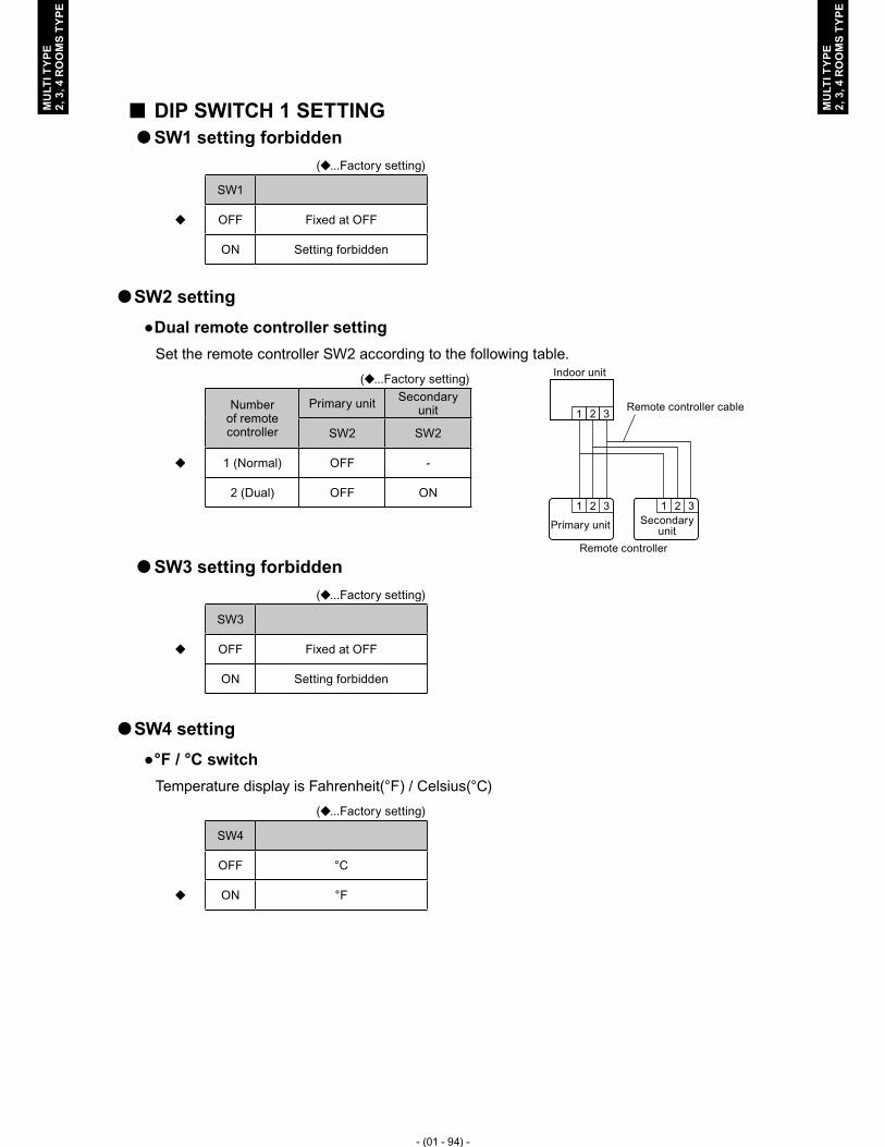
- (01 - 94) -
MU
LTI T
YPE
2, 3
, 4 R
OO
MS
TYPE
MU
LTI T
YPE
2, 3
, 4 R
OO
MS
TYPE
DIP SWITCH 1 SETTING �SW1 setting forbidden �
(�...Factory setting)
SW1
� OFF Fixed at OFF
ON Setting forbidden
SW2 setting �
Dual remote controller setting ●Set the remote controller SW2 according to the following table.
(�...Factory setting)
Number of remote controller
Primary unit Secondary unit
SW2 SW2
� 1 (Normal) OFF -
2 (Dual) OFF ON
SW3 setting forbidden �
(�...Factory setting)
SW3
� OFF Fixed at OFF
ON Setting forbidden
SW4 setting �
°F / °C switch ●Temperature display is Fahrenheit(°F) / Celsius(°C)
(�...Factory setting)
SW4
OFF °C
� ON °F
1 2 31 2 3
1 2 3
Indoor unit
Remote controller cable
Primary unit Secondary unit
Remote controller

- (01 - 95) -
MU
LTI T
YPE
2, 3
, 4 R
OO
MS
TYPE
MU
LTI T
YPE
2, 3
, 4 R
OO
MS
TYPE
SW5 setting forbidden �
(�...Factory setting)
SW5
� OFF Fixed at OFF
ON Setting forbidden
SW6 setting �
Memory backup setting (Wired remote controller only) ●Set to ON to use batteries for the memory backup.If batteries are not used, all of settings stored in memory will be deleted if there is a power failure.
(�...Factory setting)
SW6 Memory backup
� OFF Invalidity
ON Validity
Never turn it ON in the case of simple remote controller.

- (01 - 96) -
MU
LTI T
YPE
2, 3
, 4 R
OO
MS
TYPE
MU
LTI T
YPE
2, 3
, 4 R
OO
MS
TYPE
SIMPLE REMOTE CONTROLLER13-7.
DIP Switch
SW1 Forbidden
SW2 Dual remote controller setting
SW3 °F / °C switch
SW4 Forbidden
SW5 Forbidden
SW6 Forbidden
SWITCH POSITION �Simple remote controller �
1 2 3 4 5 6
DIP Switch
ON
OFF

- (01 - 97) -
MU
LTI T
YPE
2, 3
, 4 R
OO
MS
TYPE
MU
LTI T
YPE
2, 3
, 4 R
OO
MS
TYPE
DIP SWITCH SETTING �SW1 setting forbidden �
(�...Factory setting)
SW1
� OFF Fixed at OFF
ON Setting forbidden
SW2 setting �
Dual remote controller setting ●Set the remote controller SW2 according to the following table.
(�...Factory setting)
Number of remote controller
Primary unit Secondary unit
SW2 SW2
� 1 (Normal) OFF -
2 (Dual) OFF ON
SW3 setting �
°F / °C switch ●Temperature display is Fahrenheit(°F) / Celsius(°C)
(�...Factory setting)
SW3
OFF °C
� ON °F
SW4 setting forbidden �
(�...Factory setting)
SW4
� OFF Fixed at OFF
ON Setting forbidden
1 2 31 2 3
1 2 3
Indoor unit
Remote controller cable
Primary unit Secondary unit
Remote controller

- (01 - 98) -
MU
LTI T
YPE
2, 3
, 4 R
OO
MS
TYPE
MU
LTI T
YPE
2, 3
, 4 R
OO
MS
TYPE
SW5 setting forbidden �
(�...Factory setting)
SW5
� OFF Fixed at OFF
ON Setting forbidden
SW6 setting forbidden �
(�...Factory setting)
SW6
� OFF Fixed at OFF
ON Setting forbidden
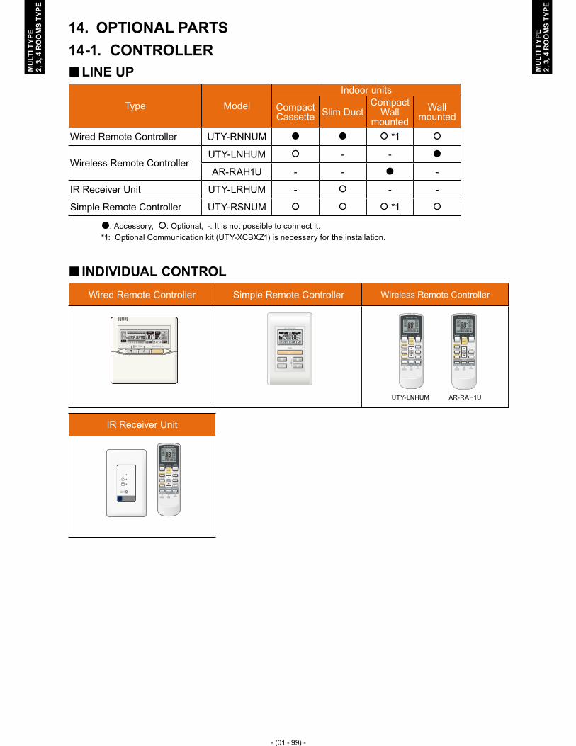
- (01 - 99) -
MU
LTI T
YPE
2, 3
, 4 R
OO
MS
TYPE
MU
LTI T
YPE
2, 3
, 4 R
OO
MS
TYPE
OPTIONAL PARTS14. CONTROLLER14-1.
LINE UP �
Type ModelIndoor units
Compact Cassette Slim Duct
Compact Wall
mountedWall
mounted
Wired Remote Controller UTY-RNNUM � � � *1 �
Wireless Remote ControllerUTY-LNHUM � - - �
AR-RAH1U - - � -
IR Receiver Unit UTY-LRHUM - � - -
Simple Remote Controller UTY-RSNUM � � � *1 �
�: Accessory, �: Optional, -: It is not possible to connect it.*1: Optional Communication kit (UTY-XCBXZ1) is necessary for the installation.
INDIVIDUAL CONTROL �
Wired Remote Controller Simple Remote Controller Wireless Remote Controller
UTY-LNHUM AR-RAH1U
IR Receiver Unit
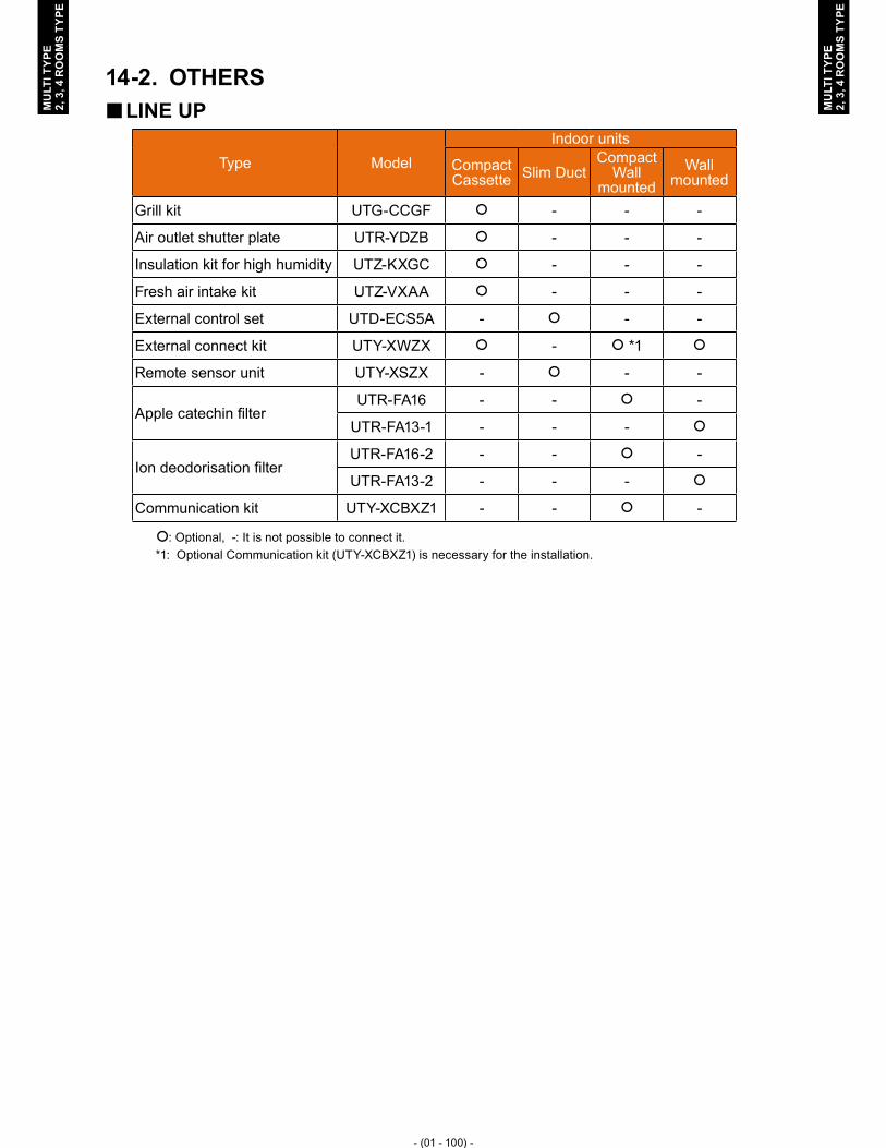
- (01 - 100) -
MU
LTI T
YPE
2, 3
, 4 R
OO
MS
TYPE
MU
LTI T
YPE
2, 3
, 4 R
OO
MS
TYPE
OTHERS14-2. LINE UP �
Type ModelIndoor units
Compact Cassette Slim Duct
Compact Wall
mountedWall
mounted
Grill kit UTG-CCGF � - - -
Air outlet shutter plate UTR-YDZB � - - -
Insulation kit for high humidity UTZ-KXGC � - - -
Fresh air intake kit UTZ-VXAA � - - -
External control set UTD-ECS5A - � - -
External connect kit UTY-XWZX � - � *1 �
Remote sensor unit UTY-XSZX - � - -
Apple catechin filterUTR-FA16 - - � -
UTR-FA13-1 - - - �
Ion deodorisation filterUTR-FA16-2 - - � -
UTR-FA13-2 - - - �
Communication kit UTY-XCBXZ1 - - � -
�: Optional, -: It is not possible to connect it.*1: Optional Communication kit (UTY-XCBXZ1) is necessary for the installation.

- (01 - 101) -
MU
LTI T
YPE
2, 3
, 4 R
OO
MS
TYPE
MU
LTI T
YPE
2, 3
, 4 R
OO
MS
TYPE
PARTS �
Air outlet shutter plate Models : UTR-YDZB
For Compact Cassette type
Grille kit Model : UTG-CCGF
For Compact Cassette type
Insulation kit for high humidity Model : UTZ-KXGC
Insulation Kit
For Compact Cassette type
Fresh air intake kit Model : UTZ-VXAA
For Compact Cassette type
External connect kitModel : UTY-XWZX
( x 1 ) ( x 1 )
For Compact Cassette / Compact Wall Mounted / Wall Mounted
External control set Model : UTD-ECS5A
( x 1 ) ( x 2 )
( x 1 ) ( x 2 )
For Slim Duct type
Remote Sensor Unit Model : UTY-XSZX
For Slim Duct type

- (01 - 102) -
MU
LTI T
YPE
2, 3
, 4 R
OO
MS
TYPE
MU
LTI T
YPE
2, 3
, 4 R
OO
MS
TYPE
PARTS �
Apple catechin filter Model : UTR-FA13-1
(9315361011) *1
For Wall mounted type
Apple catechin filter Model : UTR-FA16
(9315361035) *1
For Compact wall mounted type
Ion deodorization filter Model : UTR-FA16-2
(9315361042) *1
For Compact wall mounted type
Ion deodorization filter Model : UTR-FA13-2
(9315361028) *1
For Wall mounted type
Communication kit Model : UTY-XCBXZ1
For Compact wall mounted type
*1: Use this part number when ordering this accessory.

- (01 - 103) -
MU
LTI T
YPE
2, 3
, 4 R
OO
MS
TYPE
MU
LTI T
YPE
2, 3
, 4 R
OO
MS
TYPE
INSTALLATION PRECAUTIONS15. INDOOR UNIT INSTALLATION PRECAUTIONS15-1.
Note: The information listed below are general precautions. Some models also include items that do not apply.
PLACES WHERE USE PROHIBITED �•Places where there is the danger of combustible gas leakage.•Places where sulfur gas, chlorine gas, acid, alkali, or other matter which effects equipment is generated•Places where there is a lot of oil splash and steam (kitchen, machinery room, etc.)•Places where machinery which generates high frequencies is used•Ocean beaches and other areas where there is a lot of salt•Places where carbon fibers and metal powder, powder, etc. suspended in the air•Installation in vehicles, ships, and other conveyances•Factory, etc. where voltage fluctuations are large
POINTS TO REMEMBER WHEN INSTALLING �(1) The set shall be installed at a place which can withstand the weight and vibration of the indoor unit(2) To allow maintenance after refrigerant piping, drain piping, and electric wiring connection and installation, provide an installation service space and an inspection port, as required. *Installation service space is shown on " DIMENSIONS ".(3) Be careful when installing the set at the following places.
[Installation precautions]
Contents Countermeasures (Reference)
When theceiling is high
If the indoor unit is installed where the installation heightgiven in the installation manual is exceeded, the temperaturedifference between the floor and ceiling of the room will belarge and the heating effect will be poor.Moreover, even if the indoor unit is installed within theinstallation height, a similar phenomena will occur wheninstalled in a room in which the doors are opened and closedfrequently and hot air circulation is obstructed by desks, chairs,etc.
(1) Switch the setting to the high ceiling mode.
(2) Install a circulator.
(3) Arrange the furniture in the room so that it does not obstruct the hot air.
When lower leveldirectly contactsthe outside air.
When the lower level of the shop and office is a warehouse,parking lot, etc., the surface temperature of the flooringwill become low and the radiation of cold from the floor willincrease.In this case, your feet will feel cold even if the roomtemperature is suitable.
When the air flow distribution is poor
When an indoor unit is installed in a position where the outletair flow will directly contact people, a draft may be felt.In addition, when there are obstructions in the path of theintake and outlet air flow, the air distribution may becomeextremely bad.
(1) Adjust the louver fins or take other measures matched to the site.
(2)Change the indoor unit outlet.

- (01 - 104) -
MU
LTI T
YPE
2, 3
, 4 R
OO
MS
TYPE
MU
LTI T
YPE
2, 3
, 4 R
OO
MS
TYPE
[Installation precautions]
Contents Countermeasures (Reference)When inside the ceiling is high temperature and high humidity
When the indoor unit is installed where the inside of the ceiling is 30°C (86°F) RH80% or greater, the dew point temperature of the
outer perimeter may become higher than the cabinet surface temperature and moisture will condense on the surface of the cabinet and water drops may fall inside the room.
→Refer to Fig.A
In addition, the humidity may vary considerably the same as when the inside of the ceiling is close to hermetically sealed and used as the outside air intake path.
Add heat insulating material to (1) the outside of the indoor unit cabinet.*Regarding the cassette type, use of the “high humidity correspondence kit (option)” is recommended.
Strengthen the heat insulating (2) material of the refrigerant piping and drain piping also
→Refer to Fig.B
When the humidity inside the (3) ceiling changes considerably, install a ventilation port
Moist air curve Condition which requires addition of outside heat insulation
Relative humidity 80%
Dry bulb temperature 30°C (86°F)
Fig.A
Work method when reinforcing the heat insulation of on-site piping
Fig.B
Slit of heat insulating material facing upward
Covered gas pipe (heat insulation strengthened)
Heat insulating material (procured at the site)
Small exposed part of copper pipe is desirable.
Fit tightly (purpose is to cover the sealant)
Binding material
Flare connection
To indoor unit
Heat insulation reinforcement material (procured at the site)
Contents Countermeasures (Reference)When using an external duct
When using an external duct to take in new fresh air, etc., condensation may form on the surface of the duct due to the effect of the outside air temperature and the humidity inside the ceiling.
Always perform heat insulation (1) processing.(Heat insulating material: Glass wool 25mm (31/32 in.) thick or more.)
When the remote
controller installation site is bad
If the cold or warm air blown out from the air conditioner directly contacts the thermostat section of the remote controller, the outlet temperature of the air conditioner may be
sensed and room temperature control will be different from the room temperature and “not cooled” or “not heated” or other trouble may occur.
In addition, there is the possbility that the same kind of trouble may also occur when the remote controller is effected by direct sunlight.
Install the remote controller (1) where it will not be directly exposed to the cold or hot air.
Install the remote controller (2) where it will not be directly exposed to sunlight or strong lighting

- (01 - 105) -
MU
LTI T
YPE
2, 3
, 4 R
OO
MS
TYPE
MU
LTI T
YPE
2, 3
, 4 R
OO
MS
TYPE
[Installation precautions]
Contents Countermeasures (Reference)When installation
environment is quiet
When the wall mounting type was installed in a bedroom, living room, or other quiet place, the sound of the refrigerant flow may be sensed as noise and must be taken into accunt.
Plan installation of a model (1) with external expansion valve.
Plan installation of a branch (2) box farther from indoor unit.
Plan installation using another (3) air conditioner.
When installing duct type in ceiling chamber
system
In the case of the ceiling chamber system (duct is not installed at indoor unit inlet side and room air is sucked into the indoor
unit through the inside of the ceiling), the thermistor inside the indoor unit may not correctly detect the room temperature.
Heating operation: Room is not heated because the indoor unit is easily turned off by the thermostat. Cooling operation: Room is too cold because the indoor unit is difficult to turn off by the
thermostat.
Replace the indoor unit (1) thermistor with a Remote sensor unit (optional parts) and install the sensor where the room temperature can be correctly detected
When the outlet air is sucked in at duct type
Cooling operation does not cool the room and heating operation does not heat the room because the short circuited indoor unit is not turned on by the thermostat.
Reconsider the ventilation port (1) construction
Replace the indoor unit (2) thermistor with a Remote sensor unit (optional parts) and install the sensor where the room temperature can be correctly detected.
When using the wireless remote controller
Signals may not be received when using it in a room illuminated by an inverter fluorescent lamp.
Turn on the fluorescent lamp (1) and check if the indoor unit receives the signals from the remote controller. If the indoor unit does not receive the signals, consult an authorized service personnel.
When installing the inverter type
It may generate noise in TV sets, stereos and PCs. The inverter type should be (1) installed at a sufficient distance from these equipments.

2. OUTDOOR UNIT (2 ROOMS TYPE)
MULTI TYPE :AOU18RLXFZ
DTR_AO074E_032011.04.15

OU
TDO
OR
UN
ITA
OU
18R
LXFZ
OU
TDO
OR
UN
ITA
OU
18R
LXFZ
CONTENTS
2. OUTDOOR UNIT (2 ROOMS TYPE)
1. SPECIFICATIONS ........................................................................................... 02 - 01
2. DIMENSIONS ...................................................................................................... 02 - 02
3. REFRIGERANT CIRCUIT .......................................................................... 02 - 03
4. WIRING DIAGRAMS ..................................................................................... 02 - 04
5. CAPACITY TABLE .......................................................................................... 02 - 055-1. COMBINATIONS ............................................................................................... 02 - 05
5-2. COOLING CAPACITY ...................................................................................... 02 - 06
5-3. HEATING CAPACITY ....................................................................................... 02 - 09
6. CAPACITY COMPENSATION RATE FOR PIPE LENGTH AND HEIGHT DEFFERENCE ................................................................ 02 - 12
7. ADDITIONAL CHARGE CALCULATION ...................................... 02 - 15
8. AIR FLOW ............................................................................................................. 02 - 16
9. OPERATION NOISE ...................................................................................... 02 - 179-1. NOISE LEVEL CURVE ..................................................................................... 02 - 17
9-2. SOUND LEVEL CHECK POINT ..................................................................... 02 - 18
10. ELECTRIC CHARACTERISTICS ........................................................ 02 - 19
11. SAFETY DEVICES .......................................................................................... 02 - 20
12. INSTALLATION PRECAUTIONS ......................................................... 02 - 2112-1. OUTDOOR UNIT INSTALLATION PRECAUTIONS .................................... 02 - 21

- (02 - 01) -
OU
TDO
OR
UN
ITA
OU
18R
LXFZ
OU
TDO
OR
UN
ITA
OU
18R
LXFZ
SPECIFICATIONS1. Model name AOU18RLXFZPower source 1Ø 208/230V 60HzAvailable voltage range 187-264V
Connectable indoor unitNumber 2
Total capacity range 14,000 to 21,000 Btu/h
Combination of indoor unit non-Duct ASU9RLF x 2
Duct ARU9RLF x 2 Mix
Capacity
CoolingRated
Btu/h 18,000 18,000 18,000 kW 5.28 5.28 5.28
Min. - Max.Btu/h 6,100 - 21,000 6,100 - 21,000 6,100 - 21,000kW 1.8 - 6.2 1.8 - 6.2 1.8 - 6.2
HeatingRated
Btu/h 22,000 22,000 22,000 kW 6.42 6.42 6.42
Min. - Max.Btu/h 6,800 - 24,400 6,800 - 24,400 6,800 - 24,400kW 2.0 - 7.2 2.0 - 7.2 2.0 - 7.2
Input powerCooling
Rated
kW
1.44 1.49 1.46 Max. 2.06 2.14 2.10
HeatingRated 1.87 1.83 1.84 Max. 2.10 2.08 2.09
CurrentCooling
Rated
A
6.3 6.6 6.4 Max. 9.0 9.4 9.2
HeatingRated 8.2 8.0 8.1 Max. 9.2 9.1 9.2
EER Cooling Rated Btu/W 12.50 12.10 12.30 SEER �1 Cooling Rated - 18.00 16.00 17.00COP Heating Rated W/W 3.44 3.52 3.48HSPF �1 Heating Rated - 9.30 9.00 9.15Starting current A 8.2
Fan
Type × Q'ty Propeller ×1AirFlow rate
CoolingCFM(m3/h)
1,795 (3,050)Heating 1,619 (2,750)
MotorType × Quantity DC motor ×1Output W 100
Sound pressure levelCooling Rated
dB(A)49
Heating Rated 49
Heat exchanger
Dimension (H x W x D) in.(mm) 26-7/16 × 35-7/16 × 1-7/16 (672×900×36.38)Fin pitch FPI 18Rows × Stages 2 × 32 Pipe type (Material) Grooved H-pin (Copper)
FinType (Material) Corrugate (Aluminum)Surface treatment Corrosion resistance (Blue Fin)
CompressorType × Quantity DC TWIN ROTARY ×1Motor output W 1,100
Refrigerant Type R410ACharge lbs.(g) 4lbs. 14oz. (2,200)
Refrigerant oil Type POE
EnclosureMaterial Painted galvanized steel
Color BEIGE (Approximate color of MUNSELL 10YR 7.5/1.0NN)
DimensionsNet
(H x W x D) in.(mm)27-9/16 × 35-7/16 × 13 (700×900×330)
Gross 32-7/8 × 41-11/32 × 17-17/32 (835×1,050×445)
WeightNet
lbs.(kg)119 (54)
Gross 134 (61)
Connection pipe
SizeLiquid
in.(mm)1/4 (6.35) x2
Gas 3/8(9.52) x2Method FlarePre-charge length (Total)
ft.(m)
98 (30)Max. length (Total) 164 (50)Max. length (Each) 82 (25)Min. length (Total) 49 (15)Min. length (Each) 16 (5)Max. height difference betweenOutdoor Unit and each Indoor Units. 49 (15)
Max. height difference betweenIndoor Units. 33 (10)
Operation rangeCooling
°F(°C)14 to 115 (-10 to 46)
Heating 5 to 75 (-15 to 24)
Note:1. Specifications are based on the following conditions. Power source of specifications : 230V Pipe length : 24.6ft.(7.5m), Height difference : 0 ft.(0m) [Outdoor unit - Indoor unit] Cooling: Indoor temperature of 80°F(26.7°C)DB / 67°F(19.4°C)WB,and outdoor temperature of 95°F(35°C)DB/75°F(23.9°C)WB. Heating: Indoor temperature of 70°F(21.1°C)DB / 60°F(15.6°C)WB,and outdoor temperature of 47°F(8.3°C)DB/43°F(6.1°C)WB. �1: Test conditions are based on AHRI 210/240.2. For other combination, refer to the combination table. 3. The protective function might work when using it outside the operation range.

- (02 - 02) -
OU
TDO
OR
UN
ITA
OU
18R
LXFZ
OU
TDO
OR
UN
ITA
OU
18R
LXFZ
DIMENSIONS2. MODEL � : AOU18RLXFZ
[Unit: inch (mm)]
INSTALLATION PLACE �[Unit: inch (mm)]
25-5/8 (600)or more
3-15/16 (100)or more
*23-
5/8
(600
)to
39-3
/8 (1
000)
11-13/16 (300)or more
*3-15/16 (100)to
11-13/16 (300) 9-27/32 (250) or more
(Service space)
9-27/32 (250)or more
9-27/32 (250)or more 11-13/16 (300)
or more
When there are obstacles at the back or front sides.
When there are obstacles at the back, side(s), and top.
When there are obstacles at the back, side with the installation of more than one unit.
* If the space is larger that is stated, the condition will be the same as that are no obstacles.
Top view
Front view Side view
35-7/16 (900)
27-9
/16
(700
)
13/1
6 (2
1)
11/3
2(9
)
1-9/16(40)
1-7/32(31)
15/32(12)13 (330)
15-3/4 (400)
4-1/
2 (1
14)
2-1/
4 (5
7)15/32(12)
3-11
/16
(94)
1-5/8(41)
Bottom view
14-7
/8 (3
70)
25-19/32 (650)
4-Ø15/32 (Ø12)
Drain cap mounting places Drain pipe mounting places

- (02 - 03) -
OU
TDO
OR
UN
ITA
OU
18R
LXFZ
OU
TDO
OR
UN
ITA
OU
18R
LXFZ
REFRIGERANT CIRCUIT3. MODEL � : AOU18RLXFZ

- (02 - 04) -
OU
TDO
OR
UN
ITA
OU
18R
LXFZ
OU
TDO
OR
UN
ITA
OU
18R
LXFZ
WIRING DIAGRAMS4. MODEL � : AOU18RLXFZ

- (02 - 05) -
OU
TDO
OR
UN
ITA
OU
18R
LXFZ
OU
TDO
OR
UN
ITA
OU
18R
LXFZ
CAPACITY TABLE5. COMBINATIONS5-1.
MODEL � : AOU18RLXFZCooling �
Combination of indoor unit Type of indoor unit
Rated capacity for each indoor unit
[kBTU/h]
Maximum capacity for each indoor unit
[kBTU/h]Total capacity [kBTU/h] Input power [kW]
Room 1 Room 2 Total Room 1 Room 2 Room 1 Room 2 Min Rated Max Min Rated Max7 7 14 Non-ducted 7.05 7.05 8.70 8.70 6.10 14.10 17.40 0.50 1.30 1.64 7 9 16 Non-ducted 7.09 9.11 8.66 11.14 6.10 16.20 19.80 0.50 1.44 1.81 7 9 16 ducted 7.09 9.11 8.66 11.14 6.10 16.20 19.80 0.50 1.49 1.86 7 12 19 Non-ducted 6.63 11.37 7.74 13.26 6.10 18.00 21.00 0.50 1.43 2.06 7 12 19 ducted 6.63 11.37 7.74 13.26 6.10 18.00 21.00 0.50 1.48 2.11 9 9 18 Non-ducted 9.00 9.00 10.50 10.50 6.10 18.00 21.00 0.50 1.44 2.06 9 9 18 ducted 9.00 9.00 10.50 10.50 6.10 18.00 21.00 0.50 1.49 2.14 9 12 21 Non-ducted 7.71 10.29 9.00 12.00 6.10 18.00 21.00 0.50 1.44 2.06 9 12 21 ducted 7.71 10.29 9.00 12.00 6.10 18.00 21.00 0.50 1.49 2.14
Heating �
Combination of indoor unit Type of indoor unit
Rated capacity for each indoor unit
[kBTU/h]
Maximum capacity for each indoor unit
[kBTU/h]Total capacity [kBTU/h] Input power [kW]
Room 1 Room 2 Total Room 1 Room 2 Room 1 Room 2 Min Rated Max Min Rated Max7 7 14 Non-ducted 9.20 9.20 10.35 10.35 6.80 18.40 20.70 0.52 1.50 1.97 7 9 16 Non-ducted 8.93 11.48 9.58 12.32 6.80 20.40 21.90 0.52 1.77 1.92 7 9 16 ducted 8.93 11.48 9.58 12.32 6.80 20.40 21.90 0.52 1.73 1.90 7 12 19 Non-ducted 8.11 13.89 8.99 15.41 6.80 22.00 24.40 0.52 1.87 2.10 7 12 19 ducted 8.11 13.89 8.99 15.41 6.80 22.00 24.40 0.52 1.83 2.08 9 9 18 Non-ducted 11.00 11.00 12.20 12.20 6.80 22.00 24.40 0.52 1.87 2.10 9 9 18 ducted 11.00 11.00 12.20 12.20 6.80 22.00 24.40 0.52 1.83 2.08 9 12 21 Non-ducted 9.43 12.57 10.46 13.94 6.80 22.00 24.40 0.52 1.88 2.10 9 12 21 ducted 9.43 12.57 10.46 13.94 6.80 22.00 24.40 0.52 1.84 2.08
Note:1. Specifications are based on the following conditions.
Power source of specifications : 230VPipe length : 24.6ft.(7.5m), Height difference : 0 ft.(0m) [Outdoor unit - Indoor unit]Cooling: Indoor temperature of 80°F(26.7°C)DB / 67°F(19.4°C)WB,and outdoor temperature of 95°F(35°C)DB/75°F(23.9°C)WB.Heating: Indoor temperature of 70°F(21.1°C)DB / 60°F(15.6°C)WB,and outdoor temperature of 47°F(8.3°C)DB/43°F(6.1°C)WB.
2. The total ability of connected a indoor unit is up to 21,000BTU from 14,000BTU.3. Non-Ducted system combinations input are based on ASU wall mount models. The input of combinations including AUU cassette models may be a
little higher.4. Ducted system combinations capacities are based on ARU slim duct units with the exception of 7,000BTU models are based on ASU wall mount
models.

- (02 - 06) -
OU
TDO
OR
UN
ITA
OU
18R
LXFZ
OU
TDO
OR
UN
ITA
OU
18R
LXFZ
COOLING CAPACITY5-2. This table is created using the maximum capacity.
MODEL � : AOU18RLXFZIndoor unit : 7000BTU + 7000BTU �
Indoor temperature64 °FDB 70 °FDB 75 °FDB 80 °FDB 85 °FDB 90 °FDB54 °F WB 60 °FWB 63 °FWB 67 °FWB 71 °FWB 73 °FWB
Out
door
tem
pera
ture
( °FDB) TC SHC IP TC SHC IP TC SHC IP TC SHC IP TC SHC IP TC SHC IP14 12.74 10.15 0.56 14.40 10.14 0.57 15.18 11.18 0.57 16.25 11.73 0.58 17.38 12.00 0.59 17.91 13.34 0.59 23 12.21 9.90 0.63 13.80 9.89 0.64 14.55 10.91 0.65 15.58 11.45 0.66 16.65 11.71 0.66 17.17 13.02 0.67 32 12.00 9.80 0.70 13.56 9.79 0.71 14.30 10.80 0.72 15.31 11.33 0.72 16.36 11.59 0.73 16.87 12.88 0.74 41 11.89 9.75 0.72 13.44 9.74 0.73 14.17 10.74 0.73 15.17 11.27 0.74 16.22 11.53 0.75 16.72 12.82 0.75 50 12.00 9.80 0.72 13.56 9.79 0.74 14.30 10.80 0.74 15.31 11.33 0.75 16.36 11.59 0.76 16.87 12.88 0.76 59 11.68 9.65 0.75 13.20 9.64 0.77 13.92 10.63 0.77 14.90 11.16 0.78 15.93 11.41 0.79 16.42 12.68 0.79 67 14.52 10.99 1.10 16.41 10.98 1.12 17.30 12.11 1.13 18.53 12.71 1.14 19.80 13.00 1.16 20.42 14.45 1.16 77 13.93 10.69 1.13 15.74 10.67 1.15 16.60 11.77 1.16 17.77 12.35 1.17 19.00 12.64 1.18 19.58 14.05 1.19 87 13.07 10.26 1.25 14.77 10.24 1.27 15.57 11.30 1.28 16.68 11.86 1.30 17.83 12.13 1.31 18.38 13.48 1.32 95 13.64 10.56 1.58 15.42 10.54 1.61 16.25 11.63 1.62 17.40 12.21 1.64 18.60 12.49 1.66 19.17 13.88 1.67 104 12.93 10.24 1.75 14.61 10.22 1.79 15.41 11.28 1.80 16.50 11.83 1.82 17.63 12.11 1.84 18.18 13.46 1.85 115 11.88 9.83 2.08 13.43 9.82 2.12 14.16 10.83 2.13 15.16 11.36 2.15 16.20 11.63 2.15 16.71 12.92 2.15
TC : Total capacity (kBTU/h) SHC : Sensible Heat capacity (kBTU/h) IP : Input Power (kW)
Indoor temperature17.8°CDB 21.1°CDB 23.9°CDB 26.7°CDB 29.4°CDB 32.2°CDB12.2°CWB 15.6°CWB 17.2°CWB 19.4°CWB 21.7°CWB 22.8°CWB
Out
door
tem
pera
ture
(°CDB) TC SHC IP TC SHC IP TC SHC IP TC SHC IP TC SHC IP TC SHC IP-10.0 3.73 2.97 0.56 4.22 2.97 0.57 4.45 3.28 0.57 4.76 3.44 0.58 5.09 3.52 0.59 5.25 3.91 0.59 -5.0 3.58 2.90 0.63 4.04 2.90 0.64 4.26 3.20 0.65 4.57 3.35 0.66 4.88 3.43 0.66 5.03 3.81 0.67 0.0 3.52 2.87 0.70 3.97 2.87 0.71 4.19 3.16 0.72 4.49 3.32 0.72 4.80 3.40 0.73 4.94 3.78 0.74 5.0 3.49 2.86 0.72 3.94 2.85 0.73 4.15 3.15 0.73 4.45 3.30 0.74 4.75 3.38 0.75 4.90 3.76 0.75 10.0 3.52 2.87 0.72 3.97 2.87 0.74 4.19 3.16 0.74 4.49 3.32 0.75 4.80 3.40 0.76 4.94 3.78 0.76 15.0 3.42 2.83 0.75 3.87 2.82 0.77 4.08 3.12 0.77 4.37 3.27 0.78 4.67 3.35 0.79 4.81 3.72 0.79 19.4 4.26 3.22 1.10 4.81 3.22 1.12 5.07 3.55 1.13 5.43 3.73 1.14 5.80 3.81 1.16 5.98 4.24 1.16 25.0 4.08 3.13 1.13 4.61 3.13 1.15 4.86 3.45 1.16 5.21 3.62 1.17 5.57 3.70 1.18 5.74 4.12 1.19 30.6 3.83 3.01 1.25 4.33 3.00 1.27 4.56 3.31 1.28 4.89 3.48 1.30 5.22 3.56 1.31 5.39 3.95 1.32 35.0 4.00 3.09 1.58 4.52 3.09 1.61 4.76 3.41 1.62 5.10 3.58 1.64 5.45 3.66 1.66 5.62 4.07 1.67 40.0 3.79 3.00 1.75 4.28 3.00 1.79 4.52 3.30 1.80 4.83 3.47 1.82 5.17 3.55 1.84 5.33 3.94 1.85 46.1 3.48 2.88 2.08 3.94 2.88 2.12 4.15 3.17 2.13 4.44 3.33 2.15 4.75 3.41 2.15 4.90 3.79 2.15
TC : Total capacity (kW) SHC : Sensible Heat capacity (kW) IP : Input Power (kW)
Indoor unit : 7000BTU + 9000BTU �Indoor temperature
64 °FDB 70 °FDB 75 °FDB 80 °FDB 85 °FDB 90 °FDB54 °F WB 60 °FWB 63 °FWB 67 °FWB 71 °FWB 73 °FWB
Out
door
tem
pera
ture
( °FDB) TC SHC IP TC SHC IP TC SHC IP TC SHC IP TC SHC IP TC SHC IP14 14.66 11.33 0.65 16.57 11.32 0.66 17.47 12.48 0.66 18.70 13.10 0.67 19.99 13.40 0.68 20.61 14.89 0.68 23 14.05 11.05 0.73 15.88 11.04 0.75 16.74 12.18 0.75 17.92 12.78 0.76 19.16 13.08 0.77 19.75 14.53 0.77 32 13.81 10.94 0.81 15.60 10.93 0.82 16.45 12.06 0.83 17.61 12.65 0.84 18.82 12.94 0.85 19.40 14.38 0.85 41 13.68 10.89 0.83 15.46 10.87 0.85 16.30 11.99 0.85 17.45 12.59 0.86 18.66 12.88 0.87 19.23 14.31 0.88 50 13.81 10.94 0.84 15.60 10.93 0.86 16.45 12.06 0.86 17.61 12.65 0.87 18.82 12.94 0.88 19.40 14.38 0.89 59 13.44 10.77 0.87 15.19 10.76 0.89 16.01 11.87 0.90 17.14 12.45 0.91 18.32 12.74 0.92 18.89 14.16 0.92 67 15.48 11.74 1.09 17.49 11.73 1.11 18.44 12.94 1.11 19.74 13.58 1.13 21.11 13.89 1.14 21.76 15.44 1.15 77 14.85 11.41 1.11 16.78 11.40 1.13 17.69 12.57 1.14 18.94 13.20 1.15 20.24 13.50 1.17 20.87 15.00 1.17 87 13.93 10.95 1.23 15.75 10.94 1.26 16.60 12.07 1.27 17.77 12.66 1.28 19.00 12.96 1.29 19.58 14.40 1.30 95 15.52 11.71 1.79 17.54 11.70 1.82 18.49 12.90 1.84 19.80 13.54 1.86 21.17 13.85 1.88 21.82 15.40 1.89 104 14.75 11.37 1.99 16.67 11.36 2.03 17.58 12.53 2.04 18.82 13.15 2.06 20.12 13.45 2.09 20.74 14.95 2.10 115 12.07 10.38 1.86 13.64 10.37 1.90 14.38 11.44 1.91 15.40 12.00 1.93 16.46 12.28 1.95 16.97 13.65 1.96
TC : Total capacity (kBTU/h) SHC : Sensible Heat capacity (kBTU/h) IP : Input Power (kW)
Indoor temperature17.8°CDB 21.1°CDB 23.9°CDB 26.7°CDB 29.4°CDB 32.2°CDB12.2°CWB 15.6°CWB 17.2°CWB 19.4°CWB 21.7°CWB 22.8°CWB
Out
door
tem
pera
ture
(°CDB) TC SHC IP TC SHC IP TC SHC IP TC SHC IP TC SHC IP TC SHC IP-10.0 4.30 3.32 0.65 4.86 3.32 0.66 5.12 3.66 0.66 5.48 3.84 0.67 5.86 3.93 0.68 6.04 4.37 0.68 -5.0 4.12 3.24 0.73 4.65 3.24 0.75 4.91 3.57 0.75 5.25 3.75 0.76 5.61 3.83 0.77 5.79 4.26 0.77 0.0 4.05 3.21 0.81 4.57 3.20 0.82 4.82 3.53 0.83 5.16 3.71 0.84 5.52 3.79 0.85 5.69 4.22 0.85 5.0 4.01 3.19 0.83 4.53 3.19 0.85 4.78 3.52 0.85 5.12 3.69 0.86 5.47 3.77 0.87 5.64 4.19 0.88 10.0 4.05 3.21 0.84 4.57 3.20 0.86 4.82 3.53 0.86 5.16 3.71 0.87 5.52 3.79 0.88 5.69 4.22 0.89 15.0 3.94 3.16 0.87 4.45 3.15 0.89 4.69 3.48 0.90 5.02 3.65 0.91 5.37 3.73 0.92 5.54 4.15 0.92 19.4 4.54 3.44 1.09 5.13 3.44 1.11 5.40 3.79 1.11 5.79 3.98 1.13 6.19 4.07 1.14 6.38 4.52 1.15 25.0 4.35 3.35 1.11 4.92 3.34 1.13 5.18 3.69 1.14 5.55 3.87 1.15 5.93 3.96 1.17 6.12 4.40 1.17 30.6 4.08 3.21 1.23 4.61 3.21 1.26 4.86 3.54 1.27 5.21 3.71 1.28 5.57 3.80 1.29 5.74 4.22 1.30 35.0 4.55 3.43 1.79 5.14 3.43 1.82 5.42 3.78 1.84 5.80 3.97 1.86 6.20 4.06 1.88 6.39 4.51 1.89 40.0 4.32 3.33 1.99 4.89 3.33 2.03 5.15 3.67 2.04 5.52 3.85 2.06 5.90 3.94 2.09 6.08 4.38 2.10 46.1 3.54 3.04 1.86 4.00 3.04 1.90 4.22 3.35 1.91 4.51 3.52 1.93 4.82 3.60 1.95 4.97 4.00 1.96
TC : Total capacity (kW) SHC : Sensible Heat capacity (kW) IP : Input Power (kW)

- (02 - 07) -
OU
TDO
OR
UN
ITA
OU
18R
LXFZ
OU
TDO
OR
UN
ITA
OU
18R
LXFZIndoor unit : 7000BTU + 12000BTU �
Indoor temperature64 °FDB 70 °FDB 75 °FDB 80 °FDB 85 °FDB 90 °FDB54 °F WB 60 °FWB 63 °FWB 67 °FWB 71 °FWB 73 °FWB
Out
door
tem
pera
ture
( °FDB) TC SHC IP TC SHC IP TC SHC IP TC SHC IP TC SHC IP TC SHC IP14 15.12 11.76 0.69 17.08 11.74 0.70 18.01 12.95 0.71 19.28 13.59 0.72 20.61 13.90 0.73 21.25 15.45 0.73 23 14.49 11.47 0.78 16.37 11.45 0.80 17.26 12.64 0.80 18.48 13.26 0.81 19.75 13.57 0.82 20.36 15.08 0.83 32 14.24 11.35 0.86 16.09 11.34 0.88 16.96 12.51 0.89 18.16 13.12 0.90 19.41 13.43 0.91 20.01 14.92 0.91 41 14.11 11.29 0.89 15.95 11.28 0.90 16.81 12.44 0.91 18.00 13.06 0.92 19.24 13.36 0.93 19.83 14.85 0.94 50 14.24 11.35 0.90 16.09 11.34 0.92 16.96 12.51 0.92 18.16 13.12 0.93 19.41 13.43 0.94 20.01 14.92 0.95 59 14.22 11.35 0.99 16.07 11.33 1.00 16.94 12.50 1.01 18.14 13.12 1.02 19.39 13.42 1.04 19.99 14.92 1.04 67 17.63 12.90 1.43 19.92 12.89 1.46 21.00 14.22 1.47 22.48 14.92 1.49 24.03 15.26 1.50 24.78 16.96 1.51 77 16.91 12.54 1.47 19.11 12.53 1.49 20.14 13.82 1.50 21.56 14.50 1.52 23.05 14.84 1.54 23.76 16.49 1.55 87 15.87 12.04 1.63 17.93 12.02 1.66 18.90 13.26 1.67 20.24 13.92 1.69 21.63 14.24 1.71 22.30 15.83 1.72 95 16.46 12.35 2.03 18.61 12.34 2.07 19.61 13.61 2.09 21.00 14.28 2.11 22.45 14.61 2.13 23.14 16.24 2.15 104 15.01 11.71 2.03 16.97 11.69 2.07 17.89 12.90 2.09 19.15 13.54 2.11 20.47 13.85 2.13 21.10 15.39 2.15 115 12.17 10.68 1.86 13.76 10.67 1.89 14.50 11.77 1.90 15.53 12.35 1.93 16.60 12.64 1.95 17.11 14.05 1.96
TC : Total capacity (kBTU/h) SHC : Sensible Heat capacity (kBTU/h) IP : Input Power (kW)
Indoor temperature17.8°CDB 21.1°CDB 23.9°CDB 26.7°CDB 29.4°CDB 32.2°CDB12.2°CWB 15.6°CWB 17.2°CWB 19.4°CWB 21.7°CWB 22.8°CWB
Out
door
tem
pera
ture
(°CDB) TC SHC IP TC SHC IP TC SHC IP TC SHC IP TC SHC IP TC SHC IP-10.0 4.43 3.45 0.69 5.01 3.44 0.70 5.28 3.80 0.71 5.65 3.98 0.72 6.04 4.08 0.73 6.23 4.53 0.73 -5.0 4.25 3.36 0.78 4.80 3.36 0.80 5.06 3.70 0.80 5.42 3.89 0.81 5.79 3.98 0.82 5.97 4.42 0.83 0.0 4.17 3.33 0.86 4.72 3.32 0.88 4.97 3.67 0.89 5.32 3.85 0.90 5.69 3.94 0.91 5.86 4.37 0.91 5.0 4.14 3.31 0.89 4.67 3.31 0.90 4.93 3.65 0.91 5.27 3.83 0.92 5.64 3.92 0.93 5.81 4.35 0.94 10.0 4.17 3.33 0.90 4.72 3.32 0.92 4.97 3.67 0.92 5.32 3.85 0.93 5.69 3.94 0.94 5.86 4.37 0.95 15.0 4.17 3.33 0.99 4.71 3.32 1.00 4.97 3.66 1.01 5.32 3.84 1.02 5.68 3.93 1.04 5.86 4.37 1.04 19.4 5.17 3.78 1.43 5.84 3.78 1.46 6.15 4.17 1.47 6.59 4.37 1.49 7.04 4.47 1.50 7.26 4.97 1.51 25.0 4.96 3.68 1.47 5.60 3.67 1.49 5.90 4.05 1.50 6.32 4.25 1.52 6.76 4.35 1.54 6.97 4.83 1.55 30.6 4.65 3.53 1.63 5.26 3.52 1.66 5.54 3.89 1.67 5.93 4.08 1.69 6.34 4.17 1.71 6.54 4.64 1.72 35.0 4.83 3.62 2.03 5.45 3.62 2.07 5.75 3.99 2.09 6.15 4.19 2.11 6.58 4.28 2.13 6.78 4.76 2.15 40.0 4.40 3.43 2.03 4.97 3.43 2.07 5.24 3.78 2.09 5.61 3.97 2.11 6.00 4.06 2.13 6.19 4.51 2.15 46.1 3.57 3.13 1.86 4.03 3.13 1.89 4.25 3.45 1.90 4.55 3.62 1.93 4.86 3.70 1.95 5.01 4.12 1.96
TC : Total capacity (kW) SHC : Sensible Heat capacity (kW) IP : Input Power (kW)
Indoor unit : 9000BTU + 9000BTU �Indoor temperature
64 °FDB 70 °FDB 75 °FDB 80 °FDB 85 °FDB 90 °FDB54 °F WB 60 °FWB 63 °FWB 67 °FWB 71 °FWB 73 °FWB
Out
door
tem
pera
ture
( °FDB) TC SHC IP TC SHC IP TC SHC IP TC SHC IP TC SHC IP TC SHC IP14 14.72 11.60 0.66 16.63 11.58 0.67 17.53 12.78 0.68 18.77 13.41 0.69 20.07 13.72 0.70 20.69 15.24 0.70 23 14.10 11.31 0.75 15.94 11.30 0.76 16.80 12.46 0.77 17.99 13.08 0.78 19.23 13.38 0.79 19.82 14.87 0.79 32 13.86 11.20 0.83 15.66 11.19 0.84 16.51 12.34 0.85 17.68 12.95 0.86 18.90 13.25 0.87 19.48 14.72 0.87 41 13.74 11.14 0.85 15.52 11.13 0.87 16.36 12.27 0.87 17.52 12.88 0.88 18.73 13.18 0.89 19.31 14.65 0.90 50 13.86 11.20 0.86 15.66 11.19 0.88 16.51 12.34 0.88 17.68 12.95 0.89 18.90 13.25 0.90 19.48 14.72 0.91 59 14.22 11.37 1.00 16.07 11.35 1.02 16.94 12.52 1.03 18.14 13.14 1.04 19.39 13.45 1.05 19.99 14.94 1.06 67 16.60 12.49 1.28 18.76 12.47 1.30 19.78 13.76 1.31 21.17 14.44 1.33 22.63 14.77 1.34 23.33 16.42 1.35 77 15.92 12.14 1.31 17.99 12.12 1.33 18.97 13.37 1.34 20.31 14.03 1.36 21.71 14.36 1.37 22.38 15.96 1.38 87 14.94 11.65 1.45 16.89 11.64 1.48 17.80 12.83 1.49 19.06 13.47 1.51 20.37 13.78 1.52 21.00 15.31 1.53 95 16.46 12.38 2.06 18.61 12.36 2.10 19.61 13.63 2.12 21.00 14.31 2.14 22.45 14.64 2.15 23.14 16.27 2.15 104 14.91 11.69 2.06 16.85 11.67 2.10 17.77 12.87 2.12 19.02 13.51 2.14 20.33 13.82 2.15 20.96 15.36 2.15 115 12.04 10.65 1.88 13.60 10.64 1.92 14.34 11.73 1.93 15.35 12.31 1.95 16.41 12.60 1.98 16.92 14.00 1.99
TC : Total capacity (kBTU/h) SHC : Sensible Heat capacity (kBTU/h) IP : Input Power (kW)
Indoor temperature17.8°CDB 21.1°CDB 23.9°CDB 26.7°CDB 29.4°CDB 32.2°CDB12.2°CWB 15.6°CWB 17.2°CWB 19.4°CWB 21.7°CWB 22.8°CWB
Out
door
tem
pera
ture
(°CDB) TC SHC IP TC SHC IP TC SHC IP TC SHC IP TC SHC IP TC SHC IP-10.0 4.31 3.40 0.66 4.87 3.39 0.67 5.14 3.74 0.68 5.50 3.93 0.69 5.88 4.02 0.70 6.06 4.47 0.70 -5.0 4.13 3.32 0.75 4.67 3.31 0.76 4.92 3.65 0.77 5.27 3.83 0.78 5.64 3.92 0.79 5.81 4.36 0.79 0.0 4.06 3.28 0.83 4.59 3.28 0.84 4.84 3.62 0.85 5.18 3.79 0.86 5.54 3.88 0.87 5.71 4.31 0.87 5.0 4.03 3.27 0.85 4.55 3.26 0.87 4.80 3.60 0.87 5.13 3.78 0.88 5.49 3.86 0.89 5.66 4.29 0.90 10.0 4.06 3.28 0.86 4.59 3.28 0.88 4.84 3.62 0.88 5.18 3.79 0.89 5.54 3.88 0.90 5.71 4.31 0.91 15.0 4.17 3.33 1.00 4.71 3.33 1.02 4.97 3.67 1.03 5.32 3.85 1.04 5.68 3.94 1.05 5.86 4.38 1.06 19.4 4.87 3.66 1.28 5.50 3.66 1.30 5.80 4.03 1.31 6.21 4.23 1.33 6.63 4.33 1.34 6.84 4.81 1.35 25.0 4.67 3.56 1.31 5.27 3.55 1.33 5.56 3.92 1.34 5.95 4.11 1.36 6.36 4.21 1.37 6.56 4.68 1.38 30.6 4.38 3.41 1.45 4.95 3.41 1.48 5.22 3.76 1.49 5.59 3.95 1.51 5.97 4.04 1.52 6.16 4.49 1.53 35.0 4.83 3.63 2.06 5.45 3.62 2.10 5.75 4.00 2.12 6.15 4.19 2.14 6.58 4.29 2.15 6.78 4.77 2.15 40.0 4.37 3.42 2.06 4.94 3.42 2.10 5.21 3.77 2.12 5.57 3.96 2.14 5.96 4.05 2.15 6.14 4.50 2.15 46.1 3.53 3.12 1.88 3.99 3.12 1.92 4.20 3.44 1.93 4.50 3.61 1.95 4.81 3.69 1.98 4.96 4.10 1.99
TC : Total capacity (kW) SHC : Sensible Heat capacity (kW) IP : Input Power (kW)

- (02 - 08) -
OU
TDO
OR
UN
ITA
OU
18R
LXFZ
OU
TDO
OR
UN
ITA
OU
18R
LXFZIndoor unit : 9000BTU + 12000BTU �
Indoor temperature64 °FDB 70 °FDB 75 °FDB 80 °FDB 85 °FDB 90 °FDB54 °F WB 60 °FWB 63 °FWB 67 °FWB 71 °FWB 73 °FWB
Out
door
tem
pera
ture
( °FDB) TC SHC IP TC SHC IP TC SHC IP TC SHC IP TC SHC IP TC SHC IP14 15.31 12.02 0.72 17.31 12.00 0.73 18.24 13.24 0.74 19.53 13.89 0.75 20.88 14.22 0.76 21.52 15.80 0.76 23 14.68 11.72 0.82 16.58 11.71 0.83 17.48 12.92 0.84 18.72 13.55 0.85 20.01 13.87 0.86 20.63 15.41 0.86 32 14.42 11.61 0.90 16.30 11.59 0.92 17.18 12.79 0.92 18.39 13.42 0.93 19.66 13.73 0.95 20.27 15.26 0.95 41 14.29 11.55 0.93 16.15 11.53 0.94 17.03 12.72 0.95 18.23 13.35 0.96 19.49 13.66 0.97 20.09 15.18 0.98 50 14.42 11.61 0.94 16.30 11.59 0.95 17.18 12.79 0.96 18.39 13.42 0.97 19.66 13.73 0.98 20.27 15.26 0.99 59 14.91 11.84 1.11 16.85 11.82 1.13 17.77 13.04 1.14 19.02 13.68 1.15 20.34 14.00 1.16 20.96 15.56 1.17 67 18.38 13.42 1.59 20.77 13.40 1.62 21.90 14.78 1.63 23.45 15.51 1.65 25.06 15.87 1.67 25.84 17.64 1.68 77 17.63 13.04 1.63 19.93 13.03 1.65 21.00 14.37 1.67 22.49 15.08 1.69 24.04 15.43 1.71 24.78 17.14 1.71 87 16.55 12.52 1.80 18.70 12.50 1.84 19.71 13.79 1.85 21.10 14.47 1.87 22.56 14.81 1.89 23.26 16.45 1.90 95 16.46 12.53 2.06 18.61 12.52 2.10 19.61 13.81 2.12 21.00 14.49 2.14 22.45 14.83 2.15 23.14 16.48 2.15 104 14.76 11.76 2.02 16.68 11.75 2.06 17.58 12.96 2.08 18.83 13.60 2.10 20.12 13.91 2.12 20.75 15.46 2.14 115 11.99 10.76 1.88 13.55 10.75 1.92 14.28 11.86 1.93 15.29 12.44 1.95 16.35 12.73 1.98 16.85 14.15 1.99
TC : Total capacity (kBTU/h) SHC : Sensible Heat capacity (kBTU/h) IP : Input Power (kW)
Indoor temperature17.8°CDB 21.1°CDB 23.9°CDB 26.7°CDB 29.4°CDB 32.2°CDB12.2°CWB 15.6°CWB 17.2°CWB 19.4°CWB 21.7°CWB 22.8°CWB
Out
door
tem
pera
ture
(°CDB) TC SHC IP TC SHC IP TC SHC IP TC SHC IP TC SHC IP TC SHC IP-10.0 4.49 3.52 0.72 5.07 3.52 0.73 5.35 3.88 0.74 5.72 4.07 0.75 6.12 4.17 0.76 6.31 4.63 0.76 -5.0 4.30 3.44 0.82 4.86 3.43 0.83 5.12 3.79 0.84 5.49 3.97 0.85 5.86 4.06 0.86 6.05 4.52 0.86 0.0 4.23 3.40 0.90 4.78 3.40 0.92 5.03 3.75 0.92 5.39 3.93 0.93 5.76 4.02 0.95 5.94 4.47 0.95 5.0 4.19 3.38 0.93 4.73 3.38 0.94 4.99 3.73 0.95 5.34 3.91 0.96 5.71 4.00 0.97 5.89 4.45 0.98 10.0 4.23 3.40 0.94 4.78 3.40 0.95 5.03 3.75 0.96 5.39 3.93 0.97 5.76 4.02 0.98 5.94 4.47 0.99 15.0 4.37 3.47 1.11 4.94 3.46 1.13 5.21 3.82 1.14 5.58 4.01 1.15 5.96 4.10 1.16 6.14 4.56 1.17 19.4 5.39 3.93 1.59 6.09 3.93 1.62 6.42 4.33 1.63 6.87 4.55 1.65 7.35 4.65 1.67 7.57 5.17 1.68 25.0 5.17 3.82 1.63 5.84 3.82 1.65 6.16 4.21 1.67 6.59 4.42 1.69 7.05 4.52 1.71 7.26 5.02 1.71 30.6 4.85 3.67 1.80 5.48 3.66 1.84 5.78 4.04 1.85 6.19 4.24 1.87 6.61 4.34 1.89 6.82 4.82 1.90 35.0 4.83 3.67 2.06 5.45 3.67 2.10 5.75 4.05 2.12 6.15 4.25 2.14 6.58 4.35 2.15 6.78 4.83 2.15 40.0 4.33 3.45 2.02 4.89 3.44 2.06 5.15 3.80 2.08 5.52 3.99 2.10 5.90 4.08 2.12 6.08 4.53 2.14 46.1 3.51 3.15 1.88 3.97 3.15 1.92 4.19 3.48 1.93 4.48 3.65 1.95 4.79 3.73 1.98 4.94 4.15 1.99
TC : Total capacity (kW) SHC : Sensible Heat capacity (kW) IP : Input Power (kW)

- (02 - 09) -
OU
TDO
OR
UN
ITA
OU
18R
LXFZ
OU
TDO
OR
UN
ITA
OU
18R
LXFZ
HEATING CAPACITY5-3. This table is created using the maximum capacity.
MODEL � : AOU18RLXFZIndoor unit : 7000BTU + 7000BTU �
Indoor temperature60°FDB 65°FDB 70°FDB 75°FDB 78°FDB
Out
door
tem
pera
ture
(°FDB) (°FWB) TC IP TC IP TC IP TC IP TC IP5 3 13.01 1.82 12.60 1.88 12.18 1.93 11.75 1.99 11.49 2.02 14 12 14.68 1.94 14.22 1.99 13.74 2.05 13.26 2.11 12.97 2.14 23 19 16.52 1.90 16.00 1.95 15.46 2.01 14.92 2.07 14.59 2.10 32 28 18.62 1.84 18.04 1.90 17.43 1.95 16.82 2.01 16.45 2.04 41 37 20.74 1.79 20.09 1.84 19.41 1.89 18.73 1.95 18.32 1.98 47 43 22.12 1.86 21.42 1.91 20.70 1.97 19.98 2.03 19.54 2.06 50 47 22.29 1.88 21.58 1.93 20.85 1.99 20.12 2.05 19.68 2.08 59 50 22.51 1.90 21.80 1.95 21.06 2.01 20.32 2.07 19.88 2.10 68 59 22.07 1.66 21.37 1.71 20.65 1.76 19.93 1.80 19.49 1.83 75 65 20.19 1.11 19.55 1.14 18.89 1.17 18.23 1.20 17.83 1.22
TC : Total capacity (kBTU/h) IP : Input Power (kW)
Indoor temperature15.6°CDB 18.3°CDB 21.1°CDB 23.9°CDB 25.6°CDB
Out
door
tem
pera
ture
(°CDB) (°CWB) TC IP TC IP TC IP TC IP TC IP-15.0 -16.1 3.81 1.82 3.69 1.88 3.57 1.93 3.44 1.99 3.37 2.02 -10.0 -11.1 4.30 1.94 4.17 1.99 4.03 2.05 3.89 2.11 3.80 2.14 -5.0 -7.2 4.84 1.90 4.69 1.95 4.53 2.01 4.37 2.07 4.28 2.10 0.0 -2.2 5.46 1.84 5.29 1.90 5.11 1.95 4.93 2.01 4.82 2.04 5.0 2.8 6.08 1.79 5.89 1.84 5.69 1.89 5.49 1.95 5.37 1.98 8.3 6.1 6.48 1.86 6.28 1.91 6.07 1.97 5.85 2.03 5.73 2.06 10.0 8.3 6.53 1.88 6.33 1.93 6.11 1.99 5.90 2.05 5.77 2.08 15.0 10.0 6.60 1.90 6.39 1.95 6.17 2.01 5.96 2.07 5.83 2.10 20.0 15.0 6.47 1.66 6.26 1.71 6.05 1.76 5.84 1.80 5.71 1.83 23.9 18.3 5.92 1.11 5.73 1.14 5.54 1.17 5.34 1.20 5.22 1.22
TC : Total capacity (kW) IP : Input Power (kW)
Indoor unit : 7000BTU + 9000BTU �Indoor temperature
60°FDB 65°FDB 70°FDB 75°FDB 78°FDB
Out
door
tem
pera
ture
(°FDB) (°FWB) TC IP TC IP TC IP TC IP TC IP5 3 13.25 1.77 12.84 1.82 12.40 1.88 11.97 1.93 11.70 1.96 14 12 15.05 1.79 14.58 1.84 14.09 1.89 13.59 1.94 13.29 1.98 23 19 16.93 1.79 16.39 1.84 15.84 1.89 15.28 1.94 14.95 1.98 32 28 19.38 1.77 18.77 1.82 18.13 1.87 17.50 1.92 17.11 1.95 41 37 21.95 1.74 21.25 1.79 20.53 1.84 19.82 1.90 19.38 1.93 47 43 23.41 1.81 22.67 1.87 21.90 1.92 21.13 1.97 20.67 2.01 50 47 23.58 1.79 22.84 1.84 22.06 1.89 21.29 1.94 20.82 1.98 59 50 23.81 1.79 23.06 1.84 22.28 1.89 21.50 1.94 21.03 1.98 68 59 23.35 1.62 22.61 1.66 21.84 1.71 21.08 1.76 20.62 1.79 75 65 23.64 1.08 22.89 1.11 22.12 1.14 21.34 1.17 20.87 1.19
TC : Total capacity (kBTU/h) IP : Input Power (kW)
Indoor temperature15.6°CDB 18.3°CDB 21.1°CDB 23.9°CDB 25.6°CDB
Out
door
tem
pera
ture
(°CDB) (°CWB) TC IP TC IP TC IP TC IP TC IP-15.0 -16.1 3.88 1.77 3.76 1.82 3.63 1.88 3.51 1.93 3.43 1.96 -10.0 -11.1 4.41 1.79 4.27 1.84 4.13 1.89 3.98 1.94 3.90 1.98 -5.0 -7.2 4.96 1.79 4.80 1.84 4.64 1.89 4.48 1.94 4.38 1.98 0.0 -2.2 5.68 1.77 5.50 1.82 5.31 1.87 5.13 1.92 5.02 1.95 5.0 2.8 6.43 1.74 6.23 1.79 6.02 1.84 5.81 1.90 5.68 1.93 8.3 6.1 6.86 1.81 6.64 1.87 6.42 1.92 6.19 1.97 6.06 2.01 10.0 8.3 6.91 1.79 6.69 1.84 6.47 1.89 6.24 1.94 6.10 1.98 15.0 10.0 6.98 1.79 6.76 1.84 6.53 1.89 6.30 1.94 6.16 1.98 20.0 15.0 6.84 1.62 6.63 1.66 6.40 1.71 6.18 1.76 6.04 1.79 23.9 18.3 6.93 1.08 6.71 1.11 6.48 1.14 6.26 1.17 6.12 1.19
TC : Total capacity (kW) IP : Input Power (kW)

- (02 - 10) -
OU
TDO
OR
UN
ITA
OU
18R
LXFZ
OU
TDO
OR
UN
ITA
OU
18R
LXFZIndoor unit : 7000BTU + 12000BTU �
Indoor temperature60°FDB 65°FDB 70°FDB 75°FDB 78°FDB
Out
door
tem
pera
ture
(°FDB) (°FWB) TC IP TC IP TC IP TC IP TC IP5 3 15.02 1.95 14.54 2.00 14.05 2.06 13.56 2.12 13.26 2.15 14 12 16.95 1.96 16.42 2.02 15.86 2.08 15.31 2.14 14.97 2.15 23 19 18.86 1.96 18.26 2.02 17.65 2.08 17.03 2.14 16.65 2.15 32 28 21.65 1.94 20.97 1.99 20.26 2.05 19.55 2.11 19.12 2.14 41 37 24.45 1.91 23.68 1.96 22.88 2.02 22.08 2.07 21.59 2.11 47 43 26.08 1.98 25.25 2.04 24.40 2.10 23.55 2.15 23.03 2.15 50 47 26.27 1.96 25.44 2.02 24.58 2.08 23.72 2.14 23.20 2.15 59 50 26.53 1.96 25.69 2.01 24.83 2.07 23.96 2.13 23.43 2.15 68 59 26.01 1.57 25.19 1.62 24.34 1.66 23.49 1.71 22.97 1.74 75 65 24.13 1.28 23.37 1.31 22.58 1.35 21.79 1.39 21.31 1.41
TC : Total capacity (kBTU/h) IP : Input Power (kW)
Indoor temperature15.6°CDB 18.3°CDB 21.1°CDB 23.9°CDB 25.6°CDB
Out
door
tem
pera
ture
(°CDB) (°CWB) TC IP TC IP TC IP TC IP TC IP-15.0 -16.1 4.40 1.95 4.26 2.00 4.12 2.06 3.97 2.12 3.89 2.15 -10.0 -11.1 4.97 1.96 4.81 2.02 4.65 2.08 4.49 2.14 4.39 2.15 -5.0 -7.2 5.53 1.96 5.35 2.02 5.17 2.08 4.99 2.14 4.88 2.15 0.0 -2.2 6.35 1.94 6.14 1.99 5.94 2.05 5.73 2.11 5.60 2.14 5.0 2.8 7.17 1.91 6.94 1.96 6.71 2.02 6.47 2.07 6.33 2.11 8.3 6.1 7.64 1.98 7.40 2.04 7.15 2.10 6.90 2.15 6.75 2.15 10.0 8.3 7.70 1.96 7.46 2.02 7.20 2.08 6.95 2.14 6.80 2.15 15.0 10.0 7.78 1.96 7.53 2.01 7.28 2.07 7.02 2.13 6.87 2.15 20.0 15.0 7.62 1.57 7.38 1.62 7.13 1.66 6.88 1.71 6.73 1.74 23.9 18.3 7.07 1.28 6.85 1.31 6.62 1.35 6.39 1.39 6.25 1.41
TC : Total capacity (kW) IP : Input Power (kW)
Indoor unit : 9000BTU + 9000BTU �Indoor temperature
60°FDB 65°FDB 70°FDB 75°FDB 78°FDB
Out
door
tem
pera
ture
(°FDB) (°FWB) TC IP TC IP TC IP TC IP TC IP5 3 14.84 1.95 14.37 2.00 13.88 2.06 13.40 2.12 13.10 2.15 14 12 16.75 1.96 16.22 2.02 15.67 2.08 15.12 2.14 14.79 2.15 23 19 18.86 1.96 18.26 2.02 17.65 2.08 17.03 2.14 16.65 2.15 32 28 21.59 1.94 20.91 1.99 20.20 2.05 19.49 2.11 19.06 2.14 41 37 24.45 1.91 23.68 1.96 22.88 2.02 22.08 2.07 21.59 2.11 47 43 26.08 1.98 25.25 2.04 24.40 2.10 23.55 2.15 23.03 2.15 50 47 26.27 1.96 25.44 2.02 24.58 2.08 23.72 2.14 23.20 2.15 59 50 26.53 1.96 25.69 2.02 24.83 2.08 23.96 2.14 23.43 2.15 68 59 26.01 1.77 25.19 1.82 24.34 1.87 23.49 1.92 22.97 1.96 75 65 24.13 1.18 23.37 1.21 22.58 1.25 21.79 1.28 21.31 1.30
TC : Total capacity (kBTU/h) IP : Input Power (kW)
Indoor temperature15.6°CDB 18.3°CDB 21.1°CDB 23.9°CDB 25.6°CDB
Out
door
tem
pera
ture
(°CDB) (°CWB) TC IP TC IP TC IP TC IP TC IP-15.0 -16.1 4.35 1.95 4.21 2.00 4.07 2.06 3.93 2.12 3.84 2.15 -10.0 -11.1 4.91 1.96 4.75 2.02 4.59 2.08 4.43 2.14 4.34 2.15 -5.0 -7.2 5.53 1.96 5.35 2.02 5.17 2.08 4.99 2.14 4.88 2.15 0.0 -2.2 6.33 1.94 6.13 1.99 5.92 2.05 5.71 2.11 5.59 2.14 5.0 2.8 7.17 1.91 6.94 1.96 6.71 2.02 6.47 2.07 6.33 2.11 8.3 6.1 7.64 1.98 7.40 2.04 7.15 2.10 6.90 2.15 6.75 2.15 10.0 8.3 7.70 1.96 7.46 2.02 7.20 2.08 6.95 2.14 6.80 2.15 15.0 10.0 7.78 1.96 7.53 2.02 7.28 2.08 7.02 2.14 6.87 2.15 20.0 15.0 7.62 1.77 7.38 1.82 7.13 1.87 6.88 1.92 6.73 1.96 23.9 18.3 7.07 1.18 6.85 1.21 6.62 1.25 6.39 1.28 6.25 1.30
TC : Total capacity (kW) IP : Input Power (kW)

- (02 - 11) -
OU
TDO
OR
UN
ITA
OU
18R
LXFZ
OU
TDO
OR
UN
ITA
OU
18R
LXFZIndoor unit : 9000BTU + 12000BTU �
Indoor temperature60°FDB 65°FDB 70°FDB 75°FDB 78°FDB
Out
door
tem
pera
ture
(°FDB) (°FWB) TC IP TC IP TC IP TC IP TC IP5 3 14.87 1.95 14.40 2.01 13.91 2.06 13.42 2.12 13.13 2.15 14 12 16.78 1.97 16.25 2.03 15.70 2.09 15.15 2.15 14.82 2.15 23 19 18.86 1.97 18.26 2.03 17.65 2.09 17.03 2.15 16.65 2.15 32 28 21.59 1.94 20.91 2.00 20.20 2.05 19.49 2.11 19.06 2.15 41 37 24.45 1.91 23.68 1.96 22.88 2.02 22.08 2.07 21.59 2.11 47 43 26.08 1.98 25.25 2.04 24.40 2.10 23.55 2.15 23.03 2.15 50 47 26.27 1.97 25.44 2.03 24.58 2.09 23.72 2.15 23.20 2.15 59 50 26.53 1.96 25.69 2.02 24.83 2.07 23.96 2.13 23.43 2.15 68 59 26.01 1.57 25.19 1.62 24.34 1.66 23.49 1.71 22.97 1.74 75 65 24.12 1.28 23.36 1.31 22.57 1.35 21.78 1.39 21.30 1.41
TC : Total capacity (kBTU/h) IP : Input Power (kW)
Indoor temperature15.6°CDB 18.3°CDB 21.1°CDB 23.9°CDB 25.6°CDB
Out
door
tem
pera
ture
(°CDB) (°CWB) TC IP TC IP TC IP TC IP TC IP-15.0 -16.1 4.36 1.95 4.22 2.01 4.08 2.06 3.93 2.12 3.85 2.15 -10.0 -11.1 4.92 1.97 4.76 2.03 4.60 2.09 4.44 2.15 4.34 2.15 -5.0 -7.2 5.53 1.97 5.35 2.03 5.17 2.09 4.99 2.15 4.88 2.15 0.0 -2.2 6.33 1.94 6.13 2.00 5.92 2.05 5.71 2.11 5.59 2.15 5.0 2.8 7.17 1.91 6.94 1.96 6.71 2.02 6.47 2.07 6.33 2.11 8.3 6.1 7.64 1.98 7.40 2.04 7.15 2.10 6.90 2.15 6.75 2.15 10.0 8.3 7.70 1.97 7.46 2.03 7.20 2.09 6.95 2.15 6.80 2.15 15.0 10.0 7.78 1.96 7.53 2.02 7.28 2.07 7.02 2.13 6.87 2.15 20.0 15.0 7.62 1.57 7.38 1.62 7.13 1.66 6.88 1.71 6.73 1.74 23.9 18.3 7.07 1.28 6.85 1.31 6.61 1.35 6.38 1.39 6.24 1.41
TC : Total capacity (kW) IP : Input Power (kW)

- (02 - 12) -
OU
TDO
OR
UN
ITA
OU
18R
LXFZ
OU
TDO
OR
UN
ITA
OU
18R
LXFZ
CAPACITY COMPENSATION RATE FOR PIPE LENGTH 6. AND HEIGHT DEFFERENCE
INDOOR UNIT: 7000BTU (AOU18RLXFZ) �
Height difference H
�1 Indoor unit is upper than outdoor unit. �2 Indoor unit is under than outdoor unit.
Indoor unit
Indoor unit
Connection pipe
Outdoor unit
Outdoor unit
Connection pipe
COOLING
Pipe length
5m 7.5m 10m 15m 20m 25m
16ft. 25ft. 33ft. 49ft. 66ft. 82ft.
Height difference
H
�1 Indoor unit is upper than
outdoor unit.
15m 49ft. - - - 0.956 0.942 0.928
10m 33ft. - - 0.977 0.963 0.950 0.936
7.5m 25ft. - 0.988 0.981 0.967 0.953 0.940
5m 16ft. 0.995 0.992 0.985 0.971 0.957 0.943
0m 0ft. 1.003 1.000 0.993 0.979 0.965 0.951
�2 Indoor unit is under than outdoor unit
-5m -16ft. 1.003 1.000 0.993 0.979 0.965 0.951
-7.5m -25ft. - 1.000 0.993 0.979 0.965 0.951
-10m -33ft. - - 0.993 0.979 0.965 0.951
-15m -49ft. - - - 0.979 0.965 0.951
HEATING
Pipe length
5m 7.5m 10m 15m 20m 25m
16ft. 25ft. 33ft. 49ft. 66ft. 82ft.
Height difference
H
�1 Indoor unit is upper than
outdoor unit.
15m 49ft. - - - 0.977 0.958 0.939
10m 33ft. - - 0.993 0.977 0.958 0.939
7.5m 25ft. - 1.000 0.993 0.977 0.958 0.939
5m 16ft. 0.990 1.000 0.993 0.977 0.958 0.939
0m 0ft. 0.990 1.000 0.993 0.977 0.958 0.939
�2 Indoor unit is under than outdoor unit
-5m -16ft. 0.985 0.995 0.988 0.972 0.953 0.934
-7.5m -25ft. - 0.993 0.986 0.970 0.951 0.932
-10m -33ft. - - 0.983 0.967 0.948 0.930
-15m -49ft. - - - 0.962 0.944 0.925

- (02 - 13) -
OU
TDO
OR
UN
ITA
OU
18R
LXFZ
OU
TDO
OR
UN
ITA
OU
18R
LXFZ
INDOOR UNIT: 9000BTU (AOU18RLXFZ) �
Height difference H
�1 Indoor unit is upper than outdoor unit. �2 Indoor unit is under than outdoor unit.
Indoor unit
Indoor unit
Connection pipe
Outdoor unit
Outdoor unit
Connection pipe
COOLING
Pipe length
5m 7.5m 10m 15m 20m 25m
16ft. 25ft. 33ft. 49ft. 66ft. 82ft.
Height difference
H
�1 Indoor unit is upper than
outdoor unit.
15m 49ft. - - - 0.956 0.942 0.928
10m 33ft. - - 0.977 0.963 0.950 0.936
7.5m 25ft. - 0.988 0.981 0.967 0.953 0.940
5m 16ft. 0.999 0.992 0.985 0.971 0.957 0.943
0m 0ft. 1.007 1.000 0.993 0.979 0.965 0.951
�2 Indoor unit is under than outdoor unit
-5m -16ft. 1.007 1.000 0.993 0.979 0.965 0.951
-7.5m -25ft. - 1.000 0.993 0.979 0.965 0.951
-10m -33ft. - - 0.993 0.979 0.965 0.951
-15m -49ft. - - - 0.979 0.965 0.951
HEATING
Pipe length
5m 7.5m 10m 15m 20m 25m
16ft. 25ft. 33ft. 49ft. 66ft. 82ft.
Height difference
H
�1 Indoor unit is upper than
outdoor unit.
15m 49ft. - - - 0.977 0.958 0.939
10m 33ft. - - 0.993 0.977 0.958 0.939
7.5m 25ft. - 1.000 0.993 0.977 0.958 0.939
5m 16ft. 0.993 1.000 0.993 0.977 0.958 0.939
0m 0ft. 0.993 1.000 0.993 0.977 0.958 0.939
�2 Indoor unit is under than outdoor unit
-5m -16ft. 0.988 0.995 0.988 0.972 0.953 0.934
-7.5m -25ft. - 0.993 0.986 0.970 0.951 0.932
-10m -33ft. - - 0.983 0.967 0.948 0.930
-15m -49ft. - - - 0.962 0.944 0.925

- (02 - 14) -
OU
TDO
OR
UN
ITA
OU
18R
LXFZ
OU
TDO
OR
UN
ITA
OU
18R
LXFZ
INDOOR UNIT: 12000BTU (AOU18RLXFZ) �
Height difference H
�1 Indoor unit is upper than outdoor unit. �2 Indoor unit is under than outdoor unit.
Indoor unit
Indoor unit
Connection pipe
Outdoor unit
Outdoor unit
Connection pipe
COOLING
Pipe length
5m 7.5m 10m 15m 20m 25m
16ft. 25ft. 33ft. 49ft. 66ft. 82ft.
Height difference
H
�1 Indoor unit is upper than
outdoor unit.
15m 49ft. - - - 0.933 0.899 0.859
10m 33ft. - - 0.970 0.940 0.906 0.866
7.5m 25ft. - 0.988 0.974 0.944 0.910 0.869
5m 16ft. 1.006 0.992 0.978 0.948 0.913 0.873
0m 0ft. 1.014 1.000 0.986 0.956 0.921 0.880
�2 Indoor unit is under than outdoor unit
-5m -16ft. 1.014 1.000 0.986 0.956 0.921 0.880
-7.5m -25ft. - 1.000 0.986 0.956 0.921 0.880
-10m -33ft. - - 0.986 0.956 0.921 0.880
-15m -49ft. - - - 0.956 0.921 0.880
HEATING
Pipe length
5m 7.5m 10m 15m 20m 25m
16ft. 25ft. 33ft. 49ft. 66ft. 82ft.
Height difference
H
�1 Indoor unit is upper than
outdoor unit.
15m 49ft. - - - 0.975 0.957 0.940
10m 33ft. - - 0.990 0.975 0.957 0.940
7.5m 25ft. - 1.000 0.990 0.975 0.957 0.940
5m 16ft. 0.995 1.000 0.990 0.975 0.957 0.940
0m 0ft. 0.995 1.000 0.990 0.975 0.957 0.940
�2 Indoor unit is under than outdoor unit
-5m -16ft. 0.990 0.995 0.985 0.970 0.952 0.936
-7.5m -25ft. - 0.993 0.983 0.968 0.950 0.934
-10m -33ft. - - 0.980 0.965 0.947 0.931
-15m -49ft. - - - 0.960 0.943 0.926

- (02 - 15) -
OU
TDO
OR
UN
ITA
OU
18R
LXFZ
OU
TDO
OR
UN
ITA
OU
18R
LXFZ
ADDITIONAL CHARGE CALCULATION7. MODEL � : AOU18RLXFZ
Refrigerant charge �
Refrigerant type R410A
Refrigerant amountlbs. oz. 4 lbs. 14 oz.
g 2200
Total pipe lengthft. 98 or less 131 164 (MAX)
0.21 oz./ft.
20g/m
m 30 or less 40 50 (MAX)
Additional chargelbs. oz. 0 7.1 oz. 14.1 oz.
g 0 200 400

- (02 - 16) -
OU
TDO
OR
UN
ITA
OU
18R
LXFZ
OU
TDO
OR
UN
ITA
OU
18R
LXFZ
AIR FLOW8. MODEL � : AOU18RLXFZCooling �
Heating �
Number of rotations (r.p.m.)
Air flow
730
m3/h 3050
l/s 847
CFM 1795
Number of rotations (r.p.m.)
Air flow
660
m3/h 2750
l/s 764
CFM 1618

- (02 - 17) -
OU
TDO
OR
UN
ITA
OU
18R
LXFZ
OU
TDO
OR
UN
ITA
OU
18R
LXFZ
OPERATION NOISE9. NOISE LEVEL CURVE9-1.
MODEL � : AOU18RLXFZHeating �Cooling �
Oct
ave
band
sou
nd p
ress
ure
leve
l, dB
:(0dB
=0.0
002μ
bar)
80
70
60
50
40
30
20
10
0
NC-65
NC-60
NC-55
NC-50
NC-45
NC-40
NC-35
NC-30
NC-25
NC-20
NC-15O
ctav
e ba
nd s
ound
pre
ssur
e le
vel,
dB:(0
dB=0
.000
2μba
r)
80
70
60
50
40
30
20
10
0
NC-65
NC-60
NC-55
NC-50
NC-45
NC-40
NC-35
NC-30
NC-25
NC-20
NC-15
Octave band center frequency,Hz
63 125 250 500 1,000 2,000 4,000 8,000
Octave band center frequency,Hz
63 125 250 500 1,000 2,000 4,000 8,000

- (02 - 18) -
OU
TDO
OR
UN
ITA
OU
18R
LXFZ
OU
TDO
OR
UN
ITA
OU
18R
LXFZ
SOUND LEVEL CHECK POINT9-2.
3ft. 3-3/8in. (1m)

- (02 - 19) -
OU
TDO
OR
UN
ITA
OU
18R
LXFZ
OU
TDO
OR
UN
ITA
OU
18R
LXFZ
ELECTRIC CHARACTERISTICS10.
Model name AOU18RLXFZ
Power supply Voltage V 208 / 230 ~Frequency Hz 60
Max. operation current A 10.0 / 10.0Starting current A 8.2
*1) Wiring spec.
Main fuse (Circuit breaker) current
A 25.0
Power cable AWG 10*2) Limited wiring length ft. 107 / 118
*1) Wiring spec. : selected sample (Selected based on Japan Electrotechnical Standard and Codes Committee E0005)
*2) Limited wiring length : This is the wiring length in case voltage descent is less than 2%.When the wiring length become long, please select the wiring of a more larger diameter.

- (02 - 20) -
OU
TDO
OR
UN
ITA
OU
18R
LXFZ
OU
TDO
OR
UN
ITA
OU
18R
LXFZ
SAFETY DEVICES11.
Protection formModel
AOU18RLXFZ
Circuit protection
Current fuse (MAIN PCB)15A 250V
10A 250V
Current fuse (NEAR THE TERMINAL)
20A 250V
Fan motor protection Temperature Thermistor 266 ± 36°F OFF 212 ± 36°F ON
130 ± 20°C OFF 100 ± 20°C ON
Compressor protection Temperature Thermistor230±4°F OFF 176±4°F ON
110±2°C OFF 80±2°C ON
Refrigerant circuit protection Pressure switch (1)609±15PSI OFF 464±22PSI ON
4.2±0.1MPa OFF 3.2±0.15MPa ON
*Pressure switch (2) : For control device

- (02 - 21) -
OU
TDO
OR
UN
ITA
OU
18R
LXFZ
OU
TDO
OR
UN
ITA
OU
18R
LXFZ
INSTALLATION PRECAUTIONS12. OUTDOOR UNIT INSTALLATION PRECAUTIONS12-1.
Note: The information listed below are general precautions. Some models also include items that do not apply.
PLACES WHERE USE PROHIBITED �Places where there is the danger of combustible gas leakage •Places where sulfur gas, chlorine gas, acid, alkali, or other matter which effects equipment is •generatedPlaces not affected by heat radiation from other heat sources •Places where the air is not stagnant •Places where machinery which generates high frequencies is used •Ocean beaches and other areas where there is a lot of salt •Installation in vehicles, ships, and other conveyances •Factory, etc. where voltage fluctuations are large •
POINTS TO REMEMBER WHEN INSTALLING �The set shall be installed at a place which can withstand the weight and vibration of the outdoor (1) unitTo allow maintenance after refrigerant piping, drain piping, and electric wiring connection and (2) installation, provide an installation service space.
*Installation service space is shown on " INSTALLATION PLACE ".Be careful when installing the set at the following places.(3)
[Installation precautions]
Contents Countermeasures (Reference)When installed near adjacent houses
Perform installation work so that operating sound does not disturb the neighbors.
Install a soundproof barrier(1)
Change the installation site(2)
When there is the possibility of strong wind
If the outdoor unit is exposed to strong wind, capacity may (1) drop, frost may form during heating, and operation may be stopped by high pressure rise. In addition, when a very strong wind blows, the fan may be damaged.
When a very strong wind blows, there is the possibility (2) of the outdoor unit being toppled over if held only by foundation bolts
Install with the outlet side (1) Keep a sufficient distance away from a facing wall or fence.
Make the outlet direction and (2) wind direction perpendicular.
Fasten the outdoor unit using (3) toppling prevention hardware (procured at the site).
When snow accumulates
If the outdoor unit is covered by accumulated snow, it may not be able to operate.
Make the foundation as high as (1) possible.
Perform snow prevention work.(2) When installing the inverter type
It may generate noise in TV sets, stereos and PCs. The inverter type should be (1) installed at a sufficient distance from these equipments.

3. OUTDOOR UNIT (3 ROOMS TYPE)
MULTI TYPE :AOU24RLXFZ
DTR_AO075E_032011.04.15

OU
TDO
OR
UN
ITA
OU
24R
LXFZ
OU
TDO
OR
UN
ITA
OU
24R
LXFZ
CONTENTS
3. OUTDOOR UNIT (3 ROOMS TYPE)
1. SPECIFICATIONS ........................................................................................... 03 - 01
2. DIMENSIONS ...................................................................................................... 03 - 02
3. REFRIGERANT CIRCUIT .......................................................................... 03 - 03
4. WIRING DIAGRAMS ..................................................................................... 03 - 04
5. CAPACITY TABLE .......................................................................................... 03 - 055-1. COMBINATIONS ............................................................................................... 03 - 05
5-2. COOLING CAPACITY ...................................................................................... 03 - 06
5-3. HEATING CAPACITY ....................................................................................... 03 - 13
6. CAPACITY COMPENSATION RATE FOR PIPE LENGTH AND HEIGHT DEFFERENCE ................................................................ 03 - 20
7. ADDITIONAL CHARGE CALCULATION ...................................... 03 - 24
8. AIR FLOW ............................................................................................................. 03 - 25
9. OPERATION NOISE ...................................................................................... 03 - 269-1. NOISE LEVEL CURVE ..................................................................................... 03 - 26
9-2. SOUND LEVEL CHECK POINT ..................................................................... 03 - 27
10. ELECTRIC CHARACTERISTICS ........................................................ 03 - 28
11. SAFETY DEVICES .......................................................................................... 03 - 29
12. INSTALLATION PRECAUTIONS ......................................................... 03 - 3012-1. OUTDOOR UNIT INSTALLATION PRECAUTIONS .................................... 03 - 30

- (03 - 01) -
OU
TDO
OR
UN
ITA
OU
24R
LXFZ
OU
TDO
OR
UN
ITA
OU
24R
LXFZ
SPECIFICATIONS1. Model name AOU24RLXFZPower source 1Ø 208/230V 60HzAvailable voltage range 187-264V
Connectable indoor unitNumber 2 to 3
Total capacity range 14,000 to 27,000 Btu/h
Combination of indoor unitnon-Duct
ASU9RLF + ASU7RLF + ASU7RLF
DuctARU12RLF x 2 Mix
Capacity
CoolingRated
Btu/h 22,000 22,000 22,000kW 6.42 6.42 6.42
Min. - Max.Btu/h 6,100 - 27,000 6,100 - 25,000 6,100 - 26,000kW 1.8 - 7.9 1.8 - 7.3 1.8 - 7.6
HeatingRated
Btu/h 24,000 24,000 24,000kW 7.02 7.02 7.02
Min. - Max.Btu/h 6,800 - 29,800 6,800 - 27,400 6,800 - 28,600kW 2.0 - 8.7 2.0 - 8.0 2.0 - 8.4
Input powerCooling
Rated
kW
1.76 2.08 1.90 Max. 2.60 2.84 2.72
HeatingRated 1.73 2.05 1.88 Max. 2.93 2.93 2.93
CurrentCooling
Rated
A
7.7 9.1 8.4 Max. 11.4 12.5 12.0
HeatingRated 7.6 9.0 8.3 Max. 12.8 12.8 12.8
EER Cooling Rated Btu/W 12.50 10.60 11.55 SEER �1 Cooling Rated - 18.00 15.50 16.75COP Heating Rated W/W 4.04 3.42 3.74HSPF �1 Heating Rated - 9.50 9.00 9.25Starting current A 9.0
Fan
Type × Q'ty Propeller ×1AirFlow rate
CoolingCFM(m3/h)
1,942 ( 3,300 )Heating 1,942 ( 3,300 )
MotorType × Quantity DC motor ×1Output W 100
Sound pressure levelCooling Rated
dB(A)51
Heating Rated 52
Heat exchanger
Dimension (H x W x D) in.(mm) 26-7/16 × 35-7/16 × 1-7/16 (672×900×36.38)Fin pitch FPI 18Rows × Stages 2 × 32Pipe type (Material) Grooved H-pin (Copper)
FinType (Material) Corrugate (Aluminum)Surface treatment Corrosion resistance (Blue Fin)
CompressorType × Quantity DC TWIN ROTARY ×1Motor output W 1,100
Refrigerant Type R410ACharge lbs.(g) 4lbs. 14oz. (2,200)
Refrigerant oil Type POE
EnclosureMaterial Painted galvanized steel
Color BEIGE (Approximate color of MUNSELL 10YR 7.5/1.0NN)
DimensionsNet
(H x W x D) in.(mm)27-9/16 × 35-7/16 × 13 (700×900×330)
Gross 32-7/8 × 41-11/32 × 17-17/32 (835×1,050×445)
WeightNet
lbs.(kg)124 (56)
Gross 139 (63)
Connection pipe
SizeLiquid
in.(mm)1/4 (6.35) x3
Gas 3/8(9.52) x2 + 1/2(12.7) x1Method FlarePre-charge length (Total)
ft.(m)
98 (30)Max. length (Total) 164 (50)Max. length (Each) 82 (25)Min. length (Total) 49 (15)Min. length (Each) 16 (5)Max. height difference betweenOutdoor Unit and each Indoor Units. 49 (15)
Max. height difference betweenIndoor Units. 33 (10)
Operation rangeCooling
°F(°C)14 to 115 (-10 to 46)
Heating 5 to 75 (-15 to 24)
Note:1. Specifications are based on the following conditions.
Power source of specifications : 230VPipe length : 24.6ft.(7.5m), Height difference : 0 ft.(0m) [Outdoor unit - Indoor unit]Cooling: Indoor temperature of 80°F(26.7°C)DB / 67°F(19.4°C)WB,and outdoor temperature of 95°F(35°C)DB/75°F(23.9°C)WB.Heating: Indoor temperature of 70°F(21.1°C)DB / 60°F(15.6°C)WB,and outdoor temperature of 47°F(8.3°C)DB/43°F(6.1°C)WB.�1: Test conditions are based on AHRI 210/240.
2. For other combination, refer to the combination table. 3. The protective function might work when using it outside the operation range.

- (03 - 02) -
OU
TDO
OR
UN
ITA
OU
24R
LXFZ
OU
TDO
OR
UN
ITA
OU
24R
LXFZ
DIMENSIONS2. MODEL � : AOU24RLXFZ
[Unit: inch (mm)]
INSTALLATION PLACE �[Unit: inch (mm)]
25-5/8 (600)or more
3-15/16 (100)or more
*23-
5/8
(600
)to
39-3
/8 (1
000)
11-13/16 (300)or more
*3-15/16 (100)to
11-13/16 (300) 9-27/32 (250) or more
(Service space)
9-27/32 (250)or more
9-27/32 (250)or more 11-13/16 (300)
or more
When there are obstacles at the back or front sides.
When there are obstacles at the back, side(s), and top.
When there are obstacles at the back, side with the installation of more than one unit.
* If the space is larger that is stated, the condition will be the same as that are no obstacles.
4-1/
2(1
14)
8-31
/32
(228
)
2-1/
4(5
7)15/32(12)
3-11
/16
(94)
1-5/8(41)
Top view
Front view Side view
35-7/16 (900)
27-9
/16
(700
)
13/1
6 (2
1)
11/3
2(9
)
1-9/16(40)
1-7/32(31)
15/32(12)13 (330)
15-3/4 (400)
Bottom view
14-7
/8 (3
70)
25-19/32 (650)
4-Ø15/32 (Ø12)
Drain cap mounting places Drain pipe mounting places

- (03 - 03) -
OU
TDO
OR
UN
ITA
OU
24R
LXFZ
OU
TDO
OR
UN
ITA
OU
24R
LXFZ
REFRIGERANT CIRCUIT3. MODEL � : AOU24RLXFZ

- (03 - 04) -
OU
TDO
OR
UN
ITA
OU
24R
LXFZ
OU
TDO
OR
UN
ITA
OU
24R
LXFZ
WIRING DIAGRAMS4. MODEL � : AOU24RLXFZ

- (03 - 05) -
OU
TDO
OR
UN
ITA
OU
24R
LXFZ
OU
TDO
OR
UN
ITA
OU
24R
LXFZ
CAPACITY TABLE5. COMBINATIONS5-1.
MODEL � : AOU24RLXFZCooling �
Combination of indoor unit Type of indoor unit
Rated capacity for each indoor unit
[kBTU/h]
Maximum capacity for each indoor unit
[kBTU/h]
Total capacity [kBTU/h] Input power [kW]
Room 1 Room 2 Room 3 Total Room 1 Room 2 Room 3 Room 1 Room 2 Room 3 Min Rated Max Min Rated Max7 7 - 14 non-ducted 7.05 7.05 - 8.70 8.70 - 6.10 14.10 17.40 0.50 1.20 1.51 7 9 - 16 non-ducted 7.09 9.11 - 8.66 11.14 - 6.10 16.20 19.80 0.50 1.36 1.78 7 9 - 16 ducted 7.09 9.11 - 8.66 11.14 - 6.10 16.20 19.80 0.50 1.44 1.83 7 12 - 19 non-ducted 7.07 12.13 - 8.33 14.27 - 6.10 19.20 22.60 0.50 1.63 2.20 7 12 - 19 ducted 7.07 12.13 - 8.33 14.27 - 6.10 19.20 22.60 0.50 1.79 2.23 7 18 25 non-ducted 6.16 15.84 - 7.20 18.50 - 6.10 22.00 25.70 0.50 1.76 2.87 7 18 25 ducted 6.16 15.84 - 7.20 18.50 - 6.10 22.00 25.70 0.50 2.09 2.87 9 9 - 18 non-ducted 9.00 9.00 - 10.75 10.75 - 6.10 18.00 21.50 0.50 1.55 2.02 9 9 - 18 ducted 9.00 9.00 - 10.75 10.75 - 6.10 18.00 21.50 0.50 1.70 2.12 9 12 - 21 non-ducted 9.00 12.00 - 10.11 13.49 - 6.10 21.00 23.60 0.50 1.73 2.45 9 12 - 21 ducted 9.00 12.00 - 10.11 13.49 - 6.10 21.00 23.60 0.50 1.88 2.55 9 18 - 27 non-ducted 7.33 14.67 - 8.67 17.33 - 6.10 22.00 26.00 0.50 1.76 2.87 9 18 - 27 ducted 7.33 14.67 - 8.67 17.33 - 6.10 22.00 26.00 0.50 2.09 2.87 12 12 - 24 non-ducted 11.00 11.00 - 12.50 12.50 - 6.10 22.00 25.00 0.50 1.74 2.74 12 12 - 24 ducted 11.00 11.00 - 12.50 12.50 - 6.10 22.00 25.00 0.50 2.08 2.84 7 7 7 21 non-ducted 7.00 7.00 7.00 8.57 8.57 8.57 6.10 21.00 25.70 0.50 1.75 2.47 7 7 9 23 non-ducted 6.70 6.70 8.61 8.22 8.22 10.57 6.10 22.00 27.00 0.50 1.76 2.60 7 7 9 23 ducted 6.70 6.70 8.61 8.22 8.22 10.57 6.10 22.00 27.00 0.50 1.81 2.65 7 7 12 26 non-ducted 5.92 5.92 10.15 7.27 7.27 12.46 6.10 22.00 27.00 0.50 1.76 2.87 7 7 12 26 ducted 5.92 5.92 10.15 7.27 7.27 12.46 6.10 22.00 27.00 0.50 2.11 2.87 7 9 9 25 non-ducted 6.16 7.92 7.92 7.56 9.72 9.72 6.10 22.00 27.00 0.50 1.76 2.87 7 9 9 25 ducted 6.16 7.92 7.92 7.56 9.72 9.72 6.10 22.00 27.00 0.50 2.11 2.87 9 9 9 27 non-ducted 7.33 7.33 7.33 9.00 9.00 9.00 6.10 22.00 27.00 0.50 1.77 2.87 9 9 9 27 ducted 7.33 7.33 7.33 9.00 9.00 9.00 6.10 22.00 27.00 0.50 2.12 2.87
Heating �
Combination of indoor unit Type of indoor unit
Rated capacity for each indoor unit
[kBTU/h]
Maximum capacity for each indoor unit
[kBTU/h]
Total capacity [kBTU/h] Input power [kW]
Room 1 Room 2 Room 3 Total Room 1 Room 2 Room 3 Room 1 Room 2 Room 3 Min Rated Max Min Rated Max7 7 - 14 non-ducted 9.40 9.40 - 10.35 10.35 - 6.80 18.80 20.70 0.52 1.37 1.97 7 9 - 16 non-ducted 9.06 11.64 - 10.37 13.33 - 6.80 20.70 23.70 0.52 1.56 2.57 7 9 - 16 ducted 9.06 11.64 - 10.37 13.33 - 6.80 20.70 23.70 0.52 1.52 2.51 7 12 - 19 non-ducted 8.18 14.02 - 9.43 16.17 - 6.80 22.20 25.60 0.52 1.89 2.71 7 12 - 19 ducted 8.18 14.02 - 9.43 16.17 - 6.80 22.20 25.60 0.52 1.86 2.68 7 18 - 25 non-ducted 6.72 17.28 - 7.84 20.16 - 6.80 24.00 28.00 0.50 1.92 2.93 7 18 - 25 ducted 6.72 17.28 - 7.84 20.16 - 6.80 24.00 28.00 0.50 1.89 2.93 9 9 - 18 non-ducted 11.00 11.00 - 12.50 12.50 - 6.80 22.00 25.00 0.52 1.74 2.69 9 9 - 18 ducted 11.00 11.00 - 12.50 12.50 - 6.80 22.00 25.00 0.52 1.70 2.62 9 12 - 21 non-ducted 9.94 13.26 - 11.19 14.91 - 6.80 23.20 26.10 0.52 1.99 2.73 9 12 - 21 ducted 9.94 13.26 - 11.19 14.91 - 6.80 23.20 26.10 0.52 1.96 2.70 9 18 - 27 non-ducted 8.00 16.00 - 9.67 19.33 - 6.80 24.00 29.00 0.50 1.90 2.93 9 18 - 27 ducted 8.00 16.00 - 9.67 19.33 - 6.80 24.00 29.00 0.50 1.87 2.93 12 12 - 24 non-ducted 12.00 12.00 - 13.70 13.70 - 6.80 24.00 27.40 0.52 2.08 2.93 12 12 - 24 ducted 12.00 12.00 - 13.70 13.70 - 6.80 24.00 27.40 0.52 2.05 2.93 7 7 7 21 non-ducted 7.73 7.73 7.73 9.37 9.37 9.37 6.80 23.20 28.10 0.50 1.68 2.84 7 7 9 23 non-ducted 7.30 7.30 9.39 9.07 9.07 11.66 6.80 24.00 29.80 0.50 1.73 2.93 7 7 9 23 ducted 7.30 7.30 9.39 9.07 9.07 11.66 6.80 24.00 29.80 0.50 1.70 2.93 7 7 12 26 non-ducted 6.46 6.46 11.08 8.08 8.08 13.85 6.80 24.00 30.00 0.50 1.72 2.86 7 7 12 26 ducted 6.46 6.46 11.08 8.08 8.08 13.85 6.80 24.00 30.00 0.50 1.69 2.86 7 9 9 25 non-ducted 6.72 8.64 8.64 8.40 10.80 10.80 6.80 24.00 30.00 0.50 1.72 2.93 7 9 9 25 ducted 6.72 8.64 8.64 8.40 10.80 10.80 6.80 24.00 30.00 0.50 1.69 2.93 9 9 9 27 non-ducted 8.00 8.00 8.00 10.00 10.00 10.00 6.80 24.00 30.00 0.50 1.71 2.93 9 9 9 27 ducted 8.00 8.00 8.00 10.00 10.00 10.00 6.80 24.00 30.00 0.50 1.69 2.93
Note:1. Specifications are based on the following conditions.
Power source of specifications : 230VPipe length : 24.6ft.(7.5m), Height difference : 0 ft.(0m) [Outdoor unit - Indoor unit]Cooling: Indoor temperature of 80°F(26.7°C)DB / 67°F(19.4°C)WB,and outdoor temperature of 95°F(35°C)DB/75°F(23.9°C)WB.Heating: Indoor temperature of 70°F(21.1°C)DB / 60°F(15.6°C)WB,and outdoor temperature of 47°F(8.3°C)DB/43°F(6.1°C)WB.
2. The total ability of connected a indoor unit is up to 27,000BTU from 14,000BTU.3. Non-Ducted system combinations input are based on ASU wall mount models. The input of combinations including AUU cassette models may be a
little higher.4. Ducted system combinations capacites are based on ARU slim duct units with the exception of 7,000BTU models are based on ASU wall mount
models.

- (03 - 06) -
OU
TDO
OR
UN
ITA
OU
24R
LXFZ
OU
TDO
OR
UN
ITA
OU
24R
LXFZ
COOLING CAPACITY5-2. This table is created using the maximum capacity.
MODEL � : AOU24RLXFZIndoor unit : 7000BTU + 7000BTU �
Indoor temperature64 °FDB 70 °FDB 75 °FDB 80 °FDB 85 °FDB 90 °FDB54 °F WB 60 °FWB 63 °FWB 67 °FWB 71 °FWB 73 °FWB
Out
door
tem
pera
ture
( °FDB) TC SHC IP TC SHC IP TC SHC IP TC SHC IP TC SHC IP TC SHC IP14 12.74 10.15 0.51 14.40 10.14 0.52 15.18 11.18 0.53 16.25 11.73 0.53 17.38 12.00 0.54 17.91 13.34 0.54 23 12.21 9.90 0.58 13.80 9.89 0.59 14.55 10.91 0.60 15.58 11.45 0.60 16.65 11.71 0.61 17.17 13.02 0.61 32 12.00 9.80 0.64 13.56 9.79 0.65 14.30 10.80 0.66 15.31 11.33 0.67 16.36 11.59 0.67 16.87 12.88 0.68 41 11.89 9.75 0.66 13.44 9.74 0.67 14.17 10.74 0.68 15.17 11.27 0.68 16.22 11.53 0.69 16.72 12.82 0.70 50 12.00 9.80 0.67 13.56 9.79 0.68 14.30 10.80 0.68 15.31 11.33 0.69 16.36 11.59 0.70 16.87 12.88 0.70 59 11.68 9.65 0.69 13.20 9.64 0.71 13.92 10.63 0.71 14.90 11.16 0.72 15.93 11.41 0.73 16.42 12.68 0.73 67 14.52 10.99 1.01 16.41 10.98 1.03 17.30 12.11 1.04 18.53 12.71 1.05 19.80 13.00 1.06 20.42 14.45 1.07 77 13.93 10.69 1.04 15.74 10.67 1.06 16.60 11.77 1.06 17.77 12.35 1.08 19.00 12.64 1.09 19.58 14.05 1.09 87 13.07 10.26 1.15 14.77 10.24 1.17 15.57 11.30 1.18 16.68 11.86 1.19 17.83 12.13 1.21 18.38 13.48 1.21 95 13.64 10.56 1.46 15.42 10.54 1.48 16.25 11.63 1.49 17.40 12.21 1.51 18.60 12.49 1.53 19.17 13.88 1.54 104 12.94 10.24 1.62 14.62 10.22 1.64 15.41 11.28 1.66 16.50 11.84 1.68 17.64 12.11 1.70 18.18 13.46 1.70 115 12.00 9.93 1.83 13.57 9.92 1.87 14.30 10.94 1.88 15.31 11.48 1.90 16.37 11.74 1.92 16.87 13.05 1.93
TC : Total capacity (kBTU/h) SHC : Sensible Heat capacity (kBTU/h) IP : Input Power (kW)
Indoor temperature17.8°CDB 21.1°CDB 23.9°CDB 26.7°CDB 29.4°CDB 32.2°CDB12.2°CWB 15.6°CWB 17.2°CWB 19.4°CWB 21.7°CWB 22.8°CWB
Out
door
tem
pera
ture
(°CDB) TC SHC IP TC SHC IP TC SHC IP TC SHC IP TC SHC IP TC SHC IP-10.0 3.73 2.97 0.51 4.22 2.97 0.52 4.45 3.28 0.53 4.76 3.44 0.53 5.09 3.52 0.54 5.25 3.91 0.54 -5.0 3.58 2.90 0.58 4.04 2.90 0.59 4.26 3.20 0.60 4.57 3.35 0.60 4.88 3.43 0.61 5.03 3.81 0.61 0.0 3.52 2.87 0.64 3.97 2.87 0.65 4.19 3.16 0.66 4.49 3.32 0.67 4.80 3.40 0.67 4.94 3.78 0.68 5.0 3.49 2.86 0.66 3.94 2.85 0.67 4.15 3.15 0.68 4.45 3.30 0.68 4.75 3.38 0.69 4.90 3.76 0.70 10.0 3.52 2.87 0.67 3.97 2.87 0.68 4.19 3.16 0.68 4.49 3.32 0.69 4.80 3.40 0.70 4.94 3.78 0.70 15.0 3.42 2.83 0.69 3.87 2.82 0.71 4.08 3.12 0.71 4.37 3.27 0.72 4.67 3.35 0.73 4.81 3.72 0.73 19.4 4.26 3.22 1.01 4.81 3.22 1.03 5.07 3.55 1.04 5.43 3.73 1.05 5.80 3.81 1.06 5.98 4.24 1.07 25.0 4.08 3.13 1.04 4.61 3.13 1.06 4.86 3.45 1.06 5.21 3.62 1.08 5.57 3.70 1.09 5.74 4.12 1.09 30.6 3.83 3.01 1.15 4.33 3.00 1.17 4.56 3.31 1.18 4.89 3.48 1.19 5.22 3.56 1.21 5.39 3.95 1.21 35.0 4.00 3.09 1.46 4.52 3.09 1.48 4.76 3.41 1.49 5.10 3.58 1.51 5.45 3.66 1.53 5.62 4.07 1.54 40.0 3.79 3.00 1.62 4.28 3.00 1.64 4.52 3.31 1.66 4.84 3.47 1.68 5.17 3.55 1.70 5.33 3.94 1.70 46.1 3.52 2.91 1.83 3.98 2.91 1.87 4.19 3.21 1.88 4.49 3.36 1.90 4.80 3.44 1.92 4.95 3.83 1.93
TC : Total capacity (kW) SHC : Sensible Heat capacity (kW) IP : Input Power (kW)
Indoor unit : 7000BTU + 9000BTU �Indoor temperature
64 °FDB 70 °FDB 75 °FDB 80 °FDB 85 °FDB 90 °FDB54 °F WB 60 °FWB 63 °FWB 67 °FWB 71 °FWB 73 °FWB
Out
door
tem
pera
ture
( °FDB) TC SHC IP TC SHC IP TC SHC IP TC SHC IP TC SHC IP TC SHC IP14 14.66 11.33 0.64 16.57 11.32 0.65 17.47 12.48 0.65 18.70 13.10 0.66 19.99 13.40 0.67 20.61 14.89 0.67 23 14.05 11.05 0.72 15.88 11.04 0.73 16.74 12.18 0.74 17.92 12.78 0.75 19.16 13.08 0.76 19.75 14.53 0.76 32 13.81 10.94 0.80 15.60 10.93 0.81 16.45 12.06 0.82 17.61 12.65 0.83 18.82 12.94 0.84 19.40 14.38 0.84 41 13.68 10.89 0.82 15.46 10.87 0.83 16.30 11.99 0.84 17.45 12.59 0.85 18.66 12.88 0.86 19.23 14.31 0.86 50 13.81 10.94 0.83 15.60 10.93 0.84 16.45 12.06 0.85 17.61 12.65 0.86 18.82 12.94 0.87 19.40 14.38 0.87 59 13.44 10.77 0.86 15.19 10.76 0.87 16.01 11.87 0.88 17.14 12.45 0.89 18.32 12.74 0.90 18.89 14.16 0.91 67 15.48 11.74 1.07 17.49 11.73 1.09 18.44 12.94 1.10 19.74 13.58 1.11 21.11 13.89 1.12 21.76 15.44 1.13 77 14.85 11.41 1.09 16.78 11.40 1.11 17.69 12.57 1.12 18.94 13.20 1.13 20.24 13.50 1.15 20.87 15.00 1.15 87 13.93 10.95 1.21 15.75 10.94 1.24 16.60 12.07 1.25 17.77 12.66 1.26 19.00 12.96 1.27 19.58 14.40 1.28 95 15.52 11.71 1.76 17.54 11.70 1.80 18.49 12.90 1.81 19.80 13.54 1.83 21.17 13.85 1.85 21.82 15.40 1.86 104 14.75 11.37 1.96 16.67 11.36 1.99 17.58 12.53 2.01 18.82 13.15 2.03 20.12 13.45 2.05 20.74 14.95 2.07 115 12.19 10.43 1.86 13.77 10.41 1.90 14.52 11.49 1.91 15.54 12.06 1.93 16.61 12.33 1.96 17.13 13.71 1.97
TC : Total capacity (kBTU/h) SHC : Sensible Heat capacity (kBTU/h) IP : Input Power (kW)
Indoor temperature17.8°CDB 21.1°CDB 23.9°CDB 26.7°CDB 29.4°CDB 32.2°CDB12.2°CWB 15.6°CWB 17.2°CWB 19.4°CWB 21.7°CWB 22.8°CWB
Out
door
tem
pera
ture
(°CDB) TC SHC IP TC SHC IP TC SHC IP TC SHC IP TC SHC IP TC SHC IP-10.0 4.30 3.32 0.64 4.86 3.32 0.65 5.12 3.66 0.65 5.48 3.84 0.66 5.86 3.93 0.67 6.04 4.37 0.67 -5.0 4.12 3.24 0.72 4.65 3.24 0.73 4.91 3.57 0.74 5.25 3.75 0.75 5.61 3.83 0.76 5.79 4.26 0.76 0.0 4.05 3.21 0.80 4.57 3.20 0.81 4.82 3.53 0.82 5.16 3.71 0.83 5.52 3.79 0.84 5.69 4.22 0.84 5.0 4.01 3.19 0.82 4.53 3.19 0.83 4.78 3.52 0.84 5.12 3.69 0.85 5.47 3.77 0.86 5.64 4.19 0.86 10.0 4.05 3.21 0.83 4.57 3.20 0.84 4.82 3.53 0.85 5.16 3.71 0.86 5.52 3.79 0.87 5.69 4.22 0.87 15.0 3.94 3.16 0.86 4.45 3.15 0.87 4.69 3.48 0.88 5.02 3.65 0.89 5.37 3.73 0.90 5.54 4.15 0.91 19.4 4.54 3.44 1.07 5.13 3.44 1.09 5.40 3.79 1.10 5.79 3.98 1.11 6.19 4.07 1.12 6.38 4.52 1.13 25.0 4.35 3.35 1.09 4.92 3.34 1.11 5.18 3.69 1.12 5.55 3.87 1.13 5.93 3.96 1.15 6.12 4.40 1.15 30.6 4.08 3.21 1.21 4.61 3.21 1.24 4.86 3.54 1.25 5.21 3.71 1.26 5.57 3.80 1.27 5.74 4.22 1.28 35.0 4.55 3.43 1.76 5.14 3.43 1.80 5.42 3.78 1.81 5.80 3.97 1.83 6.20 4.06 1.85 6.39 4.51 1.86 40.0 4.32 3.33 1.96 4.89 3.33 1.99 5.15 3.67 2.01 5.52 3.85 2.03 5.90 3.94 2.05 6.08 4.38 2.07 46.1 3.57 3.06 1.86 4.04 3.05 1.90 4.25 3.37 1.91 4.56 3.53 1.93 4.87 3.61 1.96 5.02 4.02 1.97
TC : Total capacity (kW) SHC : Sensible Heat capacity (kW) IP : Input Power (kW)

- (03 - 07) -
OU
TDO
OR
UN
ITA
OU
24R
LXFZ
OU
TDO
OR
UN
ITA
OU
24R
LXFZ
Indoor unit : 7000BTU + 12000BTU �Indoor temperature
64 °FDB 70 °FDB 75 °FDB 80 °FDB 85 °FDB 90 °FDB54 °F WB 60 °FWB 63 °FWB 67 °FWB 71 °FWB 73 °FWB
Out
door
tem
pera
ture
( °FDB) TC SHC IP TC SHC IP TC SHC IP TC SHC IP TC SHC IP TC SHC IP14 16.27 12.65 0.73 18.39 12.64 0.74 19.38 13.94 0.75 20.75 14.63 0.76 22.18 14.96 0.77 22.87 16.63 0.77 23 15.59 12.34 0.83 17.62 12.33 0.84 18.58 13.60 0.85 19.89 14.27 0.86 21.26 14.60 0.87 21.92 16.23 0.87 32 15.32 12.22 0.91 17.31 12.20 0.93 18.25 13.46 0.94 19.54 14.12 0.95 20.89 14.45 0.96 21.54 16.06 0.96 41 15.19 12.15 0.94 17.16 12.14 0.95 18.09 13.39 0.96 19.37 14.05 0.97 20.71 14.38 0.98 21.34 15.98 0.99 50 15.32 12.22 0.95 17.31 12.20 0.97 18.25 13.46 0.98 19.54 14.12 0.99 20.89 14.45 1.00 21.54 16.06 1.00 59 15.31 12.21 1.04 17.30 12.20 1.06 18.23 13.45 1.07 19.52 14.12 1.08 20.87 14.44 1.09 21.51 16.05 1.10 67 18.97 13.89 1.51 21.44 13.87 1.54 22.60 15.30 1.55 24.20 16.05 1.57 25.87 16.43 1.59 26.66 18.26 1.60 77 18.20 13.50 1.55 20.56 13.48 1.58 21.68 14.87 1.59 23.21 15.61 1.61 24.81 15.97 1.63 25.58 17.75 1.63 87 17.08 12.96 1.72 19.30 12.94 1.75 20.34 14.27 1.76 21.78 14.98 1.78 23.28 15.32 1.80 24.00 17.03 1.81 95 17.72 13.29 2.15 20.02 13.28 2.19 21.11 14.64 2.21 22.60 15.37 2.23 24.16 15.72 2.26 24.91 17.47 2.27 104 16.80 12.89 2.39 18.99 12.87 2.43 20.02 14.20 2.45 21.43 14.90 2.48 22.91 15.25 2.50 23.62 16.94 2.52 115 13.10 11.50 2.05 14.80 11.48 2.09 15.61 12.67 2.10 16.71 13.29 2.13 17.86 13.60 2.15 18.41 15.12 2.16
TC : Total capacity (kBTU/h) SHC : Sensible Heat capacity (kBTU/h) IP : Input Power (kW)
Indoor temperature17.8°CDB 21.1°CDB 23.9°CDB 26.7°CDB 29.4°CDB 32.2°CDB12.2°CWB 15.6°CWB 17.2°CWB 19.4°CWB 21.7°CWB 22.8°CWB
Out
door
tem
pera
ture
(°CDB) TC SHC IP TC SHC IP TC SHC IP TC SHC IP TC SHC IP TC SHC IP-10.0 4.77 3.71 0.73 5.39 3.70 0.74 5.68 4.08 0.75 6.08 4.29 0.76 6.50 4.39 0.77 6.70 4.87 0.77 -5.0 4.57 3.62 0.83 5.16 3.61 0.84 5.44 3.99 0.85 5.83 4.18 0.86 6.23 4.28 0.87 6.42 4.76 0.87 0.0 4.49 3.58 0.91 5.07 3.58 0.93 5.35 3.95 0.94 5.73 4.14 0.95 6.12 4.24 0.96 6.31 4.71 0.96 5.0 4.45 3.56 0.94 5.03 3.56 0.95 5.30 3.92 0.96 5.68 4.12 0.97 6.07 4.21 0.98 6.26 4.68 0.99 10.0 4.49 3.58 0.95 5.07 3.58 0.97 5.35 3.95 0.98 5.73 4.14 0.99 6.12 4.24 1.00 6.31 4.71 1.00 15.0 4.49 3.58 1.04 5.07 3.57 1.06 5.34 3.94 1.07 5.72 4.14 1.08 6.12 4.23 1.09 6.31 4.70 1.10 19.4 5.56 4.07 1.51 6.28 4.07 1.54 6.62 4.48 1.55 7.09 4.71 1.57 7.58 4.81 1.59 7.81 5.35 1.60 25.0 5.33 3.96 1.55 6.03 3.95 1.58 6.35 4.36 1.59 6.80 4.57 1.61 7.27 4.68 1.63 7.50 5.20 1.63 30.6 5.00 3.80 1.72 5.66 3.79 1.75 5.96 4.18 1.76 6.38 4.39 1.78 6.82 4.49 1.80 7.03 4.99 1.81 35.0 5.19 3.90 2.15 5.87 3.89 2.19 6.19 4.29 2.21 6.62 4.50 2.23 7.08 4.61 2.26 7.30 5.12 2.27 40.0 4.92 3.78 2.39 5.57 3.77 2.43 5.87 4.16 2.45 6.28 4.37 2.48 6.71 4.47 2.50 6.92 4.97 2.52 46.1 3.84 3.37 2.05 4.34 3.37 2.09 4.57 3.71 2.10 4.90 3.90 2.13 5.23 3.99 2.15 5.40 4.43 2.16
TC : Total capacity (kW) SHC : Sensible Heat capacity (kW) IP : Input Power (kW)
Indoor unit : 7000BTU + 18000BTU �Indoor temperature
64 °FDB 70 °FDB 75 °FDB 80 °FDB 85 °FDB 90 °FDB54 °F WB 60 °FWB 63 °FWB 67 °FWB 71 °FWB 73 °FWB
Out
door
tem
pera
ture
( °FDB) TC SHC IP TC SHC IP TC SHC IP TC SHC IP TC SHC IP TC SHC IP14 19.44 14.44 1.05 21.97 14.42 1.06 23.16 15.91 1.07 24.80 16.70 1.08 26.51 17.08 1.10 27.33 18.98 1.10 23 18.63 14.09 1.18 21.06 14.07 1.21 22.20 15.52 1.22 23.77 16.29 1.23 25.41 16.67 1.24 26.19 18.52 1.25 32 18.31 13.95 1.31 20.69 13.93 1.33 21.81 15.37 1.34 23.35 16.12 1.36 24.96 16.50 1.37 25.74 18.33 1.38 41 18.15 13.87 1.34 20.51 13.86 1.37 21.62 15.29 1.38 23.15 16.04 1.39 24.74 16.41 1.41 25.51 18.24 1.42 50 18.31 13.95 1.36 20.69 13.93 1.38 21.81 15.37 1.39 23.35 16.12 1.41 24.96 16.50 1.43 25.74 18.33 1.43 59 18.83 14.18 1.59 21.28 14.16 1.61 22.43 15.62 1.63 24.02 16.39 1.65 25.68 16.77 1.66 26.47 18.64 1.67 67 21.52 15.38 1.94 24.32 15.36 1.97 25.64 16.95 1.99 27.45 17.78 2.01 29.34 18.19 2.04 30.25 20.22 2.05 77 20.64 14.95 1.98 23.33 14.93 2.02 24.59 16.47 2.04 26.33 17.28 2.06 28.14 17.68 2.08 29.01 19.65 2.09 87 19.37 14.35 2.20 21.89 14.33 2.24 23.08 15.81 2.26 24.71 16.59 2.28 26.41 16.97 2.31 27.23 18.86 2.32 95 20.15 14.74 2.77 22.77 14.72 2.82 24.00 16.24 2.84 25.70 17.04 2.87 27.47 17.44 2.90 28.32 19.38 2.92 104 16.90 13.31 2.31 19.10 13.30 2.35 20.13 14.67 2.37 21.55 15.39 2.40 23.04 15.75 2.43 23.75 17.50 2.44 115 12.43 11.69 1.81 14.04 11.68 1.84 14.81 12.88 1.86 15.85 13.52 1.88 16.95 13.83 1.90 17.47 15.37 1.91
TC : Total capacity (kBTU/h) SHC : Sensible Heat capacity (kBTU/h) IP : Input Power (kW)
Indoor temperature17.8°CDB 21.1°CDB 23.9°CDB 26.7°CDB 29.4°CDB 32.2°CDB12.2°CWB 15.6°CWB 17.2°CWB 19.4°CWB 21.7°CWB 22.8°CWB
Out
door
tem
pera
ture
(°CDB) TC SHC IP TC SHC IP TC SHC IP TC SHC IP TC SHC IP TC SHC IP-10.0 5.70 4.23 1.05 6.44 4.23 1.06 6.79 4.66 1.07 7.27 4.89 1.08 7.77 5.01 1.10 8.01 5.56 1.10 -5.0 5.46 4.13 1.18 6.17 4.12 1.21 6.51 4.55 1.22 6.97 4.77 1.23 7.45 4.88 1.24 7.68 5.43 1.25 0.0 5.37 4.09 1.31 6.06 4.08 1.33 6.39 4.50 1.34 6.84 4.73 1.36 7.32 4.83 1.37 7.54 5.37 1.38 5.0 5.32 4.07 1.34 6.01 4.06 1.37 6.34 4.48 1.38 6.78 4.70 1.39 7.25 4.81 1.41 7.48 5.35 1.42 10.0 5.37 4.09 1.36 6.06 4.08 1.38 6.39 4.50 1.39 6.84 4.73 1.41 7.32 4.83 1.43 7.54 5.37 1.43 15.0 5.52 4.15 1.59 6.24 4.15 1.61 6.58 4.58 1.63 7.04 4.80 1.65 7.53 4.91 1.66 7.76 5.46 1.67 19.4 6.31 4.51 1.94 7.13 4.50 1.97 7.51 4.97 1.99 8.04 5.21 2.01 8.60 5.33 2.04 8.87 5.93 2.05 25.0 6.05 4.38 1.98 6.84 4.38 2.02 7.21 4.83 2.04 7.72 5.07 2.06 8.25 5.18 2.08 8.50 5.76 2.09 30.6 5.68 4.21 2.20 6.42 4.20 2.24 6.76 4.63 2.26 7.24 4.86 2.28 7.74 4.97 2.31 7.98 5.53 2.32 35.0 5.91 4.32 2.77 6.67 4.32 2.82 7.04 4.76 2.84 7.53 5.00 2.87 8.05 5.11 2.90 8.30 5.68 2.92 40.0 4.95 3.90 2.31 5.60 3.90 2.35 5.90 4.30 2.37 6.32 4.51 2.40 6.75 4.62 2.43 6.96 5.13 2.44 46.1 3.64 3.43 1.81 4.12 3.42 1.84 4.34 3.77 1.86 4.65 3.96 1.88 4.97 4.05 1.90 5.12 4.50 1.91
TC : Total capacity (kW) SHC : Sensible Heat capacity (kW) IP : Input Power (kW)

- (03 - 08) -
OU
TDO
OR
UN
ITA
OU
24R
LXFZ
OU
TDO
OR
UN
ITA
OU
24R
LXFZ
Indoor unit : 9000BTU + 9000BTU �Indoor temperature
64 °FDB 70 °FDB 75 °FDB 80 °FDB 85 °FDB 90 °FDB54 °F WB 60 °FWB 63 °FWB 67 °FWB 71 °FWB 73 °FWB
Out
door
tem
pera
ture
( °FDB) TC SHC IP TC SHC IP TC SHC IP TC SHC IP TC SHC IP TC SHC IP14 15.07 11.87 0.66 17.03 11.86 0.67 17.95 13.08 0.67 19.22 13.73 0.68 20.54 14.04 0.69 21.18 15.61 0.69 23 14.44 11.58 0.74 16.32 11.57 0.76 17.20 12.76 0.76 18.42 13.39 0.77 19.69 13.70 0.78 20.30 15.23 0.78 32 14.19 11.47 0.82 16.03 11.45 0.84 16.90 12.63 0.84 18.10 13.26 0.85 19.35 13.56 0.86 19.94 15.07 0.87 41 14.06 11.41 0.84 15.89 11.39 0.86 16.75 12.57 0.86 17.94 13.19 0.87 19.17 13.49 0.88 19.77 14.99 0.89 50 14.19 11.47 0.85 16.03 11.45 0.87 16.90 12.63 0.88 18.10 13.26 0.89 19.35 13.56 0.90 19.94 15.07 0.90 59 14.56 11.64 0.99 16.45 11.62 1.01 17.35 12.82 1.02 18.57 13.46 1.03 19.85 13.77 1.04 20.47 15.30 1.05 67 16.99 12.78 1.27 19.21 12.77 1.29 20.25 14.08 1.30 21.68 14.78 1.32 23.17 15.12 1.33 23.89 16.81 1.34 77 16.30 12.43 1.30 18.42 12.41 1.32 19.42 13.69 1.33 20.79 14.37 1.35 22.23 14.70 1.36 22.91 16.34 1.37 87 15.30 11.93 1.44 17.29 11.91 1.46 18.22 13.14 1.48 19.51 13.79 1.49 20.86 14.11 1.51 21.50 15.68 1.52 95 16.86 12.67 2.04 19.05 12.66 2.08 20.08 13.96 2.10 21.50 14.65 2.12 22.98 14.99 2.14 23.69 16.66 2.16 104 15.98 12.29 2.27 18.06 12.27 2.31 19.04 13.54 2.33 20.39 14.20 2.35 21.80 14.53 2.38 22.47 16.15 2.39 115 12.45 10.96 1.90 14.07 10.94 1.94 14.83 12.07 1.95 15.88 12.67 1.97 16.98 12.96 2.00 17.50 14.40 2.01
TC : Total capacity (kBTU/h) SHC : Sensible Heat capacity (kBTU/h) IP : Input Power (kW)
Indoor temperature17.8°CDB 21.1°CDB 23.9°CDB 26.7°CDB 29.4°CDB 32.2°CDB12.2°CWB 15.6°CWB 17.2°CWB 19.4°CWB 21.7°CWB 22.8°CWB
Out
door
tem
pera
ture
(°CDB) TC SHC IP TC SHC IP TC SHC IP TC SHC IP TC SHC IP TC SHC IP-10.0 4.42 3.48 0.66 4.99 3.48 0.67 5.26 3.83 0.67 5.63 4.02 0.68 6.02 4.12 0.69 6.21 4.57 0.69 -5.0 4.23 3.39 0.74 4.78 3.39 0.76 5.04 3.74 0.76 5.40 3.92 0.77 5.77 4.02 0.78 5.95 4.46 0.78 0.0 4.16 3.36 0.82 4.70 3.36 0.84 4.95 3.70 0.84 5.30 3.88 0.85 5.67 3.97 0.86 5.84 4.42 0.87 5.0 4.12 3.34 0.84 4.66 3.34 0.86 4.91 3.68 0.86 5.26 3.86 0.87 5.62 3.95 0.88 5.79 4.39 0.89 10.0 4.16 3.36 0.85 4.70 3.36 0.87 4.95 3.70 0.88 5.30 3.88 0.89 5.67 3.97 0.90 5.84 4.42 0.90 15.0 4.27 3.41 0.99 4.82 3.41 1.01 5.08 3.76 1.02 5.44 3.94 1.03 5.82 4.03 1.04 6.00 4.48 1.05 19.4 4.98 3.75 1.27 5.63 3.74 1.29 5.93 4.13 1.30 6.35 4.33 1.32 6.79 4.43 1.33 7.00 4.93 1.34 25.0 4.78 3.64 1.30 5.40 3.64 1.32 5.69 4.01 1.33 6.09 4.21 1.35 6.51 4.31 1.36 6.72 4.79 1.37 30.6 4.48 3.50 1.44 5.07 3.49 1.46 5.34 3.85 1.48 5.72 4.04 1.49 6.11 4.13 1.51 6.30 4.60 1.52 35.0 4.94 3.71 2.04 5.58 3.71 2.08 5.89 4.09 2.10 6.30 4.29 2.12 6.74 4.39 2.14 6.94 4.88 2.16 40.0 4.68 3.60 2.27 5.29 3.60 2.31 5.58 3.97 2.33 5.98 4.16 2.35 6.39 4.26 2.38 6.59 4.73 2.39 46.1 3.65 3.21 1.90 4.12 3.21 1.94 4.35 3.54 1.95 4.65 3.71 1.97 4.98 3.80 2.00 5.13 4.22 2.01
TC : Total capacity (kW) SHC : Sensible Heat capacity (kW) IP : Input Power (kW)
Indoor unit : 9000BTU + 12000BTU �Indoor temperature
64 °FDB 70 °FDB 75 °FDB 80 °FDB 85 °FDB 90 °FDB54 °F WB 60 °FWB 63 °FWB 67 °FWB 71 °FWB 73 °FWB
Out
door
tem
pera
ture
( °FDB) TC SHC IP TC SHC IP TC SHC IP TC SHC IP TC SHC IP TC SHC IP14 15.69 12.43 0.71 17.73 12.42 0.72 18.69 13.70 0.72 20.01 14.37 0.73 21.39 14.71 0.74 22.05 16.34 0.74 23 15.04 12.13 0.80 16.99 12.12 0.81 17.91 13.36 0.82 19.18 14.02 0.83 20.50 14.35 0.84 21.13 15.95 0.84 32 14.77 12.01 0.88 16.70 11.99 0.90 17.60 13.23 0.91 18.84 13.88 0.92 20.15 14.20 0.93 20.77 15.78 0.93 41 14.64 11.95 0.91 16.55 11.93 0.92 17.45 13.16 0.93 18.68 13.81 0.94 19.97 14.13 0.95 20.58 15.70 0.96 50 14.77 12.01 0.92 16.70 11.99 0.93 17.60 13.23 0.94 18.84 13.88 0.95 20.15 14.20 0.96 20.77 15.78 0.97 59 15.28 12.24 1.08 17.27 12.23 1.10 18.20 13.49 1.11 19.49 14.16 1.12 20.84 14.48 1.14 21.48 16.10 1.14 67 18.83 13.88 1.56 21.28 13.86 1.58 22.44 15.29 1.60 24.02 16.05 1.61 25.68 16.42 1.63 26.47 18.25 1.64 77 18.07 13.49 1.59 20.42 13.48 1.62 21.52 14.87 1.63 23.04 15.60 1.65 24.63 15.96 1.67 25.39 17.74 1.68 87 16.95 12.95 1.77 19.16 12.93 1.80 20.20 14.27 1.81 21.62 14.97 1.83 23.12 15.32 1.85 23.83 17.02 1.86 95 18.50 13.68 2.46 20.91 13.66 2.50 22.04 15.07 2.52 23.60 15.82 2.55 25.23 16.18 2.58 26.01 17.99 2.59 104 16.63 12.86 2.35 18.79 12.84 2.39 19.81 14.17 2.41 21.21 14.87 2.44 22.67 15.21 2.46 23.37 16.90 2.48 115 12.42 11.30 1.89 14.03 11.28 1.92 14.79 12.45 1.94 15.84 13.06 1.96 16.93 13.36 1.98 17.45 14.85 1.99
TC : Total capacity (kBTU/h) SHC : Sensible Heat capacity (kBTU/h) IP : Input Power (kW)
Indoor temperature17.8°CDB 21.1°CDB 23.9°CDB 26.7°CDB 29.4°CDB 32.2°CDB12.2°CWB 15.6°CWB 17.2°CWB 19.4°CWB 21.7°CWB 22.8°CWB
Out
door
tem
pera
ture
(°CDB) TC SHC IP TC SHC IP TC SHC IP TC SHC IP TC SHC IP TC SHC IP-10.0 4.60 3.64 0.71 5.20 3.64 0.72 5.48 4.01 0.72 5.87 4.21 0.73 6.27 4.31 0.74 6.46 4.79 0.74 -5.0 4.41 3.56 0.80 4.98 3.55 0.81 5.25 3.92 0.82 5.62 4.11 0.83 6.01 4.21 0.84 6.19 4.67 0.84 0.0 4.33 3.52 0.88 4.89 3.51 0.90 5.16 3.88 0.91 5.52 4.07 0.92 5.90 4.16 0.93 6.09 4.63 0.93 5.0 4.29 3.50 0.91 4.85 3.50 0.92 5.11 3.86 0.93 5.47 4.05 0.94 5.85 4.14 0.95 6.03 4.60 0.96 10.0 4.33 3.52 0.92 4.89 3.51 0.93 5.16 3.88 0.94 5.52 4.07 0.95 5.90 4.16 0.96 6.09 4.63 0.97 15.0 4.48 3.59 1.08 5.06 3.58 1.10 5.34 3.95 1.11 5.71 4.15 1.12 6.11 4.24 1.14 6.30 4.72 1.14 19.4 5.52 4.07 1.56 6.24 4.06 1.58 6.58 4.48 1.60 7.04 4.70 1.61 7.53 4.81 1.63 7.76 5.35 1.64 25.0 5.29 3.95 1.59 5.98 3.95 1.62 6.31 4.36 1.63 6.75 4.57 1.65 7.22 4.68 1.67 7.44 5.20 1.68 30.6 4.97 3.80 1.77 5.62 3.79 1.80 5.92 4.18 1.81 6.34 4.39 1.83 6.77 4.49 1.85 6.98 4.99 1.86 35.0 5.42 4.01 2.46 6.13 4.00 2.50 6.46 4.42 2.52 6.92 4.64 2.55 7.39 4.74 2.58 7.62 5.27 2.59 40.0 4.87 3.77 2.35 5.51 3.76 2.39 5.81 4.15 2.41 6.22 4.36 2.44 6.64 4.46 2.46 6.85 4.95 2.48 46.1 3.64 3.31 1.89 4.11 3.31 1.92 4.34 3.65 1.94 4.64 3.83 1.96 4.96 3.92 1.98 5.11 4.35 1.99
TC : Total capacity (kW) SHC : Sensible Heat capacity (kW) IP : Input Power (kW)

- (03 - 09) -
OU
TDO
OR
UN
ITA
OU
24R
LXFZ
OU
TDO
OR
UN
ITA
OU
24R
LXFZ
Indoor unit : 9000BTU + 18000BTU �Indoor temperature
64 °FDB 70 °FDB 75 °FDB 80 °FDB 85 °FDB 90 °FDB54 °F WB 60 °FWB 63 °FWB 67 °FWB 71 °FWB 73 °FWB
Out
door
tem
pera
ture
( °FDB) TC SHC IP TC SHC IP TC SHC IP TC SHC IP TC SHC IP TC SHC IP14 19.67 14.86 1.05 22.23 14.84 1.06 23.43 16.37 1.07 25.09 17.18 1.08 26.82 17.57 1.10 27.65 19.53 1.10 23 18.85 14.50 1.18 21.30 14.48 1.21 22.46 15.97 1.22 24.04 16.76 1.23 25.70 17.15 1.24 26.50 19.06 1.25 32 18.52 14.35 1.31 20.93 14.33 1.33 22.07 15.81 1.34 23.63 16.59 1.36 25.26 16.97 1.37 26.04 18.86 1.38 41 18.36 14.27 1.34 20.75 14.26 1.37 21.87 15.73 1.38 23.42 16.50 1.39 25.03 16.88 1.41 25.81 18.77 1.42 50 18.52 14.35 1.36 20.93 14.33 1.38 22.07 15.81 1.39 23.63 16.59 1.41 25.26 16.97 1.43 26.04 18.86 1.43 59 19.88 14.95 1.74 22.47 14.93 1.77 23.68 16.47 1.78 25.36 17.28 1.80 27.11 17.68 1.82 27.94 19.65 1.83 67 22.10 15.96 2.00 24.97 15.94 2.04 26.32 17.58 2.05 28.18 18.45 2.08 30.13 18.88 2.10 31.06 20.98 2.11 77 21.19 15.51 2.05 23.95 15.50 2.08 25.25 17.09 2.10 27.03 17.94 2.12 28.90 18.35 2.15 29.79 20.40 2.16 87 19.89 14.89 2.27 22.48 14.87 2.31 23.70 16.40 2.33 25.37 17.21 2.36 27.12 17.61 2.38 27.96 19.57 2.40 95 20.38 15.17 2.77 23.04 15.15 2.82 24.28 16.71 2.84 26.00 17.54 2.87 27.79 17.94 2.90 28.65 19.94 2.92 104 17.00 13.65 2.31 19.21 13.63 2.35 20.25 15.04 2.37 21.68 15.78 2.40 23.18 16.15 2.43 23.89 17.94 2.44 115 12.57 12.03 1.81 14.21 12.01 1.84 14.98 13.25 1.86 16.04 13.91 1.88 17.14 14.23 1.90 17.67 15.81 1.91
TC : Total capacity (kBTU/h) SHC : Sensible Heat capacity (kBTU/h) IP : Input Power (kW)
Indoor temperature17.8°CDB 21.1°CDB 23.9°CDB 26.7°CDB 29.4°CDB 32.2°CDB12.2°CWB 15.6°CWB 17.2°CWB 19.4°CWB 21.7°CWB 22.8°CWB
Out
door
tem
pera
ture
(°CDB) TC SHC IP TC SHC IP TC SHC IP TC SHC IP TC SHC IP TC SHC IP-10.0 5.77 4.35 1.05 6.52 4.35 1.06 6.87 4.80 1.07 7.35 5.03 1.08 7.86 5.15 1.10 8.10 5.72 1.10 -5.0 5.52 4.25 1.18 6.24 4.24 1.21 6.58 4.68 1.22 7.05 4.91 1.23 7.53 5.03 1.24 7.77 5.58 1.25 0.0 5.43 4.21 1.31 6.14 4.20 1.33 6.47 4.63 1.34 6.92 4.86 1.36 7.40 4.97 1.37 7.63 5.53 1.38 5.0 5.38 4.18 1.34 6.08 4.18 1.37 6.41 4.61 1.38 6.86 4.84 1.39 7.34 4.95 1.41 7.56 5.50 1.42 10.0 5.43 4.21 1.36 6.14 4.20 1.38 6.47 4.63 1.39 6.92 4.86 1.41 7.40 4.97 1.43 7.63 5.53 1.43 15.0 5.83 4.38 1.74 6.58 4.38 1.77 6.94 4.83 1.78 7.43 5.07 1.80 7.94 5.18 1.82 8.19 5.76 1.83 19.4 6.48 4.68 2.00 7.32 4.67 2.04 7.72 5.15 2.05 8.26 5.41 2.08 8.83 5.53 2.10 9.10 6.15 2.11 25.0 6.21 4.55 2.05 7.02 4.54 2.08 7.40 5.01 2.10 7.92 5.26 2.12 8.47 5.38 2.15 8.73 5.98 2.16 30.6 5.83 4.36 2.27 6.59 4.36 2.31 6.94 4.81 2.33 7.44 5.05 2.36 7.95 5.16 2.38 8.19 5.74 2.40 35.0 5.97 4.45 2.77 6.75 4.44 2.82 7.12 4.90 2.84 7.62 5.14 2.87 8.15 5.26 2.90 8.40 5.84 2.92 40.0 4.98 4.00 2.31 5.63 4.00 2.35 5.93 4.41 2.37 6.35 4.63 2.40 6.79 4.73 2.43 7.00 5.26 2.44 46.1 3.68 3.53 1.81 4.16 3.52 1.84 4.39 3.88 1.86 4.70 4.08 1.88 5.02 4.17 1.90 5.18 4.63 1.91
TC : Total capacity (kW) SHC : Sensible Heat capacity (kW) IP : Input Power (kW)
Indoor unit : 12000BTU + 12000BTU �Indoor temperature
64 °FDB 70 °FDB 75 °FDB 80 °FDB 85 °FDB 90 °FDB54 °F WB 60 °FWB 63 °FWB 67 °FWB 71 °FWB 73 °FWB
Out
door
tem
pera
ture
( °FDB) TC SHC IP TC SHC IP TC SHC IP TC SHC IP TC SHC IP TC SHC IP14 16.79 13.20 0.80 18.97 13.19 0.82 20.00 14.55 0.82 21.41 15.27 0.83 22.89 15.62 0.84 23.60 17.36 0.85 23 16.09 12.88 0.91 18.18 12.87 0.93 19.17 14.19 0.93 20.52 14.89 0.94 21.94 15.24 0.96 22.62 16.94 0.96 32 15.81 12.75 1.00 17.87 12.74 1.02 18.83 14.05 1.03 20.17 14.74 1.04 21.56 15.08 1.05 22.22 16.76 1.06 41 15.67 12.69 1.03 17.71 12.67 1.05 18.67 13.98 1.06 19.99 14.67 1.07 21.37 15.01 1.08 22.03 16.68 1.09 50 15.81 12.75 1.04 17.87 12.74 1.06 18.83 14.05 1.07 20.17 14.74 1.08 21.56 15.08 1.10 22.22 16.76 1.10 59 16.44 13.05 1.25 18.58 13.03 1.27 19.59 14.37 1.28 20.97 15.08 1.29 22.42 15.43 1.31 23.11 17.15 1.32 67 20.60 14.93 1.86 23.28 14.91 1.89 24.54 16.45 1.90 26.28 17.26 1.92 28.09 17.66 1.95 28.96 19.63 1.96 77 19.76 14.51 1.90 22.33 14.50 1.93 23.54 15.99 1.95 25.21 16.78 1.97 26.94 17.17 1.99 27.78 19.08 2.00 87 18.54 13.93 2.11 20.96 13.91 2.14 22.09 15.35 2.16 23.65 16.10 2.18 25.29 16.48 2.21 26.07 18.31 2.22 95 19.60 14.45 2.74 22.15 14.43 2.79 23.35 15.91 2.81 25.00 16.70 2.84 26.73 17.09 2.87 27.55 18.99 2.89 104 16.86 13.24 2.40 19.05 13.22 2.44 20.09 14.58 2.46 21.51 15.30 2.49 22.99 15.66 2.52 23.70 17.40 2.53 115 12.56 11.67 1.88 14.20 11.65 1.91 14.97 12.85 1.93 16.02 13.49 1.95 17.13 13.80 1.97 17.66 15.34 1.98
TC : Total capacity (kBTU/h) SHC : Sensible Heat capacity (kBTU/h) IP : Input Power (kW)
Indoor temperature17.8°CDB 21.1°CDB 23.9°CDB 26.7°CDB 29.4°CDB 32.2°CDB12.2°CWB 15.6°CWB 17.2°CWB 19.4°CWB 21.7°CWB 22.8°CWB
Out
door
tem
pera
ture
(°CDB) TC SHC IP TC SHC IP TC SHC IP TC SHC IP TC SHC IP TC SHC IP-10.0 4.92 3.87 0.80 5.56 3.87 0.82 5.86 4.26 0.82 6.28 4.47 0.83 6.71 4.58 0.84 6.92 5.09 0.85 -5.0 4.72 3.78 0.91 5.33 3.77 0.93 5.62 4.16 0.93 6.01 4.37 0.94 6.43 4.47 0.96 6.63 4.96 0.96 0.0 4.63 3.74 1.00 5.24 3.73 1.02 5.52 4.12 1.03 5.91 4.32 1.04 6.32 4.42 1.05 6.51 4.91 1.06 5.0 4.59 3.72 1.03 5.19 3.71 1.05 5.47 4.10 1.06 5.86 4.30 1.07 6.26 4.40 1.08 6.46 4.89 1.09 10.0 4.63 3.74 1.04 5.24 3.73 1.06 5.52 4.12 1.07 5.91 4.32 1.08 6.32 4.42 1.10 6.51 4.91 1.10 15.0 4.82 3.82 1.25 5.45 3.82 1.27 5.74 4.21 1.28 6.15 4.42 1.29 6.57 4.52 1.31 6.77 5.03 1.32 19.4 6.04 4.38 1.86 6.82 4.37 1.89 7.19 4.82 1.90 7.70 5.06 1.92 8.23 5.18 1.95 8.49 5.75 1.96 25.0 5.79 4.25 1.90 6.55 4.25 1.93 6.90 4.69 1.95 7.39 4.92 1.97 7.90 5.03 1.99 8.14 5.59 2.00 30.6 5.44 4.08 2.11 6.14 4.08 2.14 6.47 4.50 2.16 6.93 4.72 2.18 7.41 4.83 2.21 7.64 5.37 2.22 35.0 5.74 4.23 2.74 6.49 4.23 2.79 6.84 4.66 2.81 7.33 4.89 2.84 7.83 5.01 2.87 8.07 5.57 2.89 40.0 4.94 3.88 2.40 5.58 3.87 2.44 5.89 4.27 2.46 6.30 4.49 2.49 6.74 4.59 2.52 6.95 5.10 2.53 46.1 3.68 3.42 1.88 4.16 3.42 1.91 4.39 3.77 1.93 4.70 3.95 1.95 5.02 4.05 1.97 5.18 4.50 1.98
TC : Total capacity (kW) SHC : Sensible Heat capacity (kW) IP : Input Power (kW)

- (03 - 10) -
OU
TDO
OR
UN
ITA
OU
24R
LXFZ
OU
TDO
OR
UN
ITA
OU
24R
LXFZ
Indoor unit : 7000BTU + 7000BTU + 7000BTU �Indoor temperature
64 °FDB 70 °FDB 75 °FDB 80 °FDB 85 °FDB 90 °FDB54 °F WB 60 °FWB 63 °FWB 67 °FWB 71 °FWB 73 °FWB
Out
door
tem
pera
ture
( °FDB) TC SHC IP TC SHC IP TC SHC IP TC SHC IP TC SHC IP TC SHC IP14 17.92 14.58 0.73 20.25 14.56 0.74 21.35 16.06 0.75 22.86 16.85 0.79 24.44 17.24 0.76 25.19 19.16 0.77 23 17.18 14.22 0.82 19.41 14.20 0.84 20.46 15.67 0.84 21.91 16.44 0.89 23.42 16.82 0.86 24.14 18.70 0.87 32 16.88 14.08 0.91 19.07 14.06 0.92 20.11 15.51 0.93 21.53 16.28 0.98 23.01 16.65 0.95 23.72 18.51 0.96 41 16.73 14.01 0.93 18.90 13.99 0.95 19.93 15.43 0.96 21.34 16.19 1.01 22.81 16.57 0.98 23.51 18.41 0.98 50 16.88 14.08 0.94 19.07 14.06 0.96 20.11 15.51 0.97 21.53 16.28 1.02 23.01 16.65 0.99 23.72 18.51 1.00 59 16.43 13.86 0.98 18.57 13.84 1.00 19.57 15.27 1.01 20.96 16.02 1.06 22.40 16.39 1.03 23.09 18.22 1.03 67 20.99 16.04 1.52 23.72 16.02 1.55 25.00 17.67 1.56 26.77 18.55 1.64 28.61 18.97 1.59 29.50 21.09 1.60 77 20.13 15.59 1.55 22.75 15.57 1.58 23.98 17.18 1.59 25.67 18.03 1.68 27.45 18.44 1.63 28.29 20.50 1.64 87 18.89 14.97 1.72 21.35 14.95 1.75 22.50 16.49 1.77 24.09 17.30 1.86 25.76 17.70 1.81 26.55 19.67 1.82 95 20.15 15.60 2.28 22.77 15.58 2.32 24.00 17.19 2.34 25.70 18.04 2.47 27.47 18.45 2.40 28.32 20.51 2.41 104 18.22 14.72 2.31 20.59 14.70 2.35 21.70 16.21 2.37 23.24 17.01 2.50 24.84 17.41 2.43 25.61 19.35 2.44 115 13.58 12.91 1.81 15.35 12.90 1.84 16.18 14.22 1.86 17.32 14.93 1.96 18.52 15.27 1.90 19.09 16.97 1.91
TC : Total capacity (kBTU/h) SHC : Sensible Heat capacity (kBTU/h) IP : Input Power (kW)
Indoor temperature17.8°CDB 21.1°CDB 23.9°CDB 26.7°CDB 29.4°CDB 32.2°CDB12.2°CWB 15.6°CWB 17.2°CWB 19.4°CWB 21.7°CWB 22.8°CWB
Out
door
tem
pera
ture
(°CDB) TC SHC IP TC SHC IP TC SHC IP TC SHC IP TC SHC IP TC SHC IP-10.0 5.25 4.27 0.73 5.94 4.27 0.74 6.26 4.71 0.75 6.70 4.94 0.79 7.16 5.05 0.76 7.38 5.62 0.77 -5.0 5.03 4.17 0.82 5.69 4.16 0.84 6.00 4.59 0.84 6.42 4.82 0.89 6.86 4.93 0.86 7.08 5.48 0.87 0.0 4.95 4.13 0.91 5.59 4.12 0.92 5.89 4.55 0.93 6.31 4.77 0.98 6.74 4.88 0.95 6.95 5.42 0.96 5.0 4.90 4.10 0.93 5.54 4.10 0.95 5.84 4.52 0.96 6.25 4.75 1.01 6.68 4.86 0.98 6.89 5.40 0.98 10.0 4.95 4.13 0.94 5.59 4.12 0.96 5.89 4.55 0.97 6.31 4.77 1.02 6.74 4.88 0.99 6.95 5.42 1.00 15.0 4.81 4.06 0.98 5.44 4.06 1.00 5.74 4.48 1.01 6.14 4.70 1.06 6.57 4.80 1.03 6.77 5.34 1.03 19.4 6.15 4.70 1.52 6.95 4.70 1.55 7.33 5.18 1.56 7.84 5.44 1.64 8.39 5.56 1.59 8.65 6.18 1.60 25.0 5.90 4.57 1.55 6.67 4.56 1.58 7.03 5.03 1.59 7.52 5.28 1.68 8.04 5.41 1.63 8.29 6.01 1.64 30.6 5.54 4.39 1.72 6.26 4.38 1.75 6.60 4.83 1.77 7.06 5.07 1.86 7.55 5.19 1.81 7.78 5.77 1.82 35.0 5.91 4.57 2.28 6.67 4.57 2.32 7.04 5.04 2.34 7.53 5.29 2.47 8.05 5.41 2.40 8.30 6.01 2.41 40.0 5.34 4.31 2.31 6.03 4.31 2.35 6.36 4.75 2.37 6.81 4.99 2.50 7.28 5.10 2.43 7.50 5.67 2.44 46.1 3.98 3.78 1.81 4.50 3.78 1.84 4.74 4.17 1.86 5.08 4.37 1.96 5.43 4.48 1.90 5.60 4.97 1.91
TC : Total capacity (kW) SHC : Sensible Heat capacity (kW) IP : Input Power (kW)
Indoor unit : 7000BTU + 7000BTU + 9000BTU �Indoor temperature
64 °FDB 70 °FDB 75 °FDB 80 °FDB 85 °FDB 90 °FDB54 °F WB 60 °FWB 63 °FWB 67 °FWB 71 °FWB 73 °FWB
Out
door
tem
pera
ture
( °FDB) TC SHC IP TC SHC IP TC SHC IP TC SHC IP TC SHC IP TC SHC IP14 18.79 15.33 0.79 21.24 15.31 0.81 22.39 16.88 0.81 23.97 17.72 0.84 25.62 18.13 0.83 26.41 20.15 0.84 23 18.01 14.95 0.90 20.35 14.93 0.92 21.45 16.47 0.92 22.97 17.29 0.95 24.55 17.69 0.94 25.31 19.66 0.95 32 17.69 14.80 0.99 20.00 14.78 1.01 21.08 16.31 1.02 22.57 17.11 1.05 24.13 17.51 1.04 24.87 19.46 1.05 41 17.54 14.72 1.02 19.82 14.71 1.04 20.89 16.22 1.04 22.37 17.02 1.08 23.91 17.42 1.07 24.65 19.36 1.07 50 17.69 14.80 1.03 20.00 14.78 1.05 21.08 16.31 1.06 22.57 17.11 1.09 24.13 17.51 1.08 24.87 19.46 1.09 59 18.01 14.95 1.18 20.36 14.94 1.20 21.46 16.48 1.21 22.98 17.29 1.25 24.56 17.69 1.24 25.32 19.66 1.24 67 22.15 16.93 1.68 25.04 16.91 1.71 26.39 18.65 1.73 28.26 19.57 1.78 30.21 20.03 1.77 31.14 22.26 1.78 77 21.25 16.46 1.72 24.01 16.44 1.75 25.32 18.13 1.77 27.10 19.03 1.82 28.97 19.47 1.81 29.87 21.64 1.82 87 19.94 15.80 1.91 22.54 15.78 1.94 23.76 17.40 1.96 25.44 18.26 2.02 27.19 18.68 2.00 28.03 20.77 2.02 95 21.17 16.42 2.51 23.92 16.40 2.55 25.22 18.09 2.57 27.00 18.99 2.65 28.86 19.42 2.63 29.75 21.59 2.64 104 18.42 15.15 2.31 20.82 15.13 2.35 21.94 16.69 2.37 23.49 17.51 2.45 25.11 17.92 2.43 25.89 19.91 2.44 115 13.69 13.32 1.81 15.47 13.30 1.84 16.30 14.68 1.86 17.46 15.40 1.92 18.66 15.76 1.90 19.24 17.51 1.91
TC : Total capacity (kBTU/h) SHC : Sensible Heat capacity (kBTU/h) IP : Input Power (kW)
Indoor temperature17.8°CDB 21.1°CDB 23.9°CDB 26.7°CDB 29.4°CDB 32.2°CDB12.2°CWB 15.6°CWB 17.2°CWB 19.4°CWB 21.7°CWB 22.8°CWB
Out
door
tem
pera
ture
(°CDB) TC SHC IP TC SHC IP TC SHC IP TC SHC IP TC SHC IP TC SHC IP-10.0 5.51 4.49 0.79 6.22 4.49 0.81 6.56 4.95 0.81 7.02 5.19 0.84 7.51 5.31 0.83 7.74 5.90 0.84 -5.0 5.28 4.38 0.90 5.96 4.38 0.92 6.29 4.83 0.92 6.73 5.07 0.95 7.20 5.18 0.94 7.42 5.76 0.95 0.0 5.19 4.34 0.99 5.86 4.33 1.01 6.18 4.78 1.02 6.61 5.01 1.05 7.07 5.13 1.04 7.29 5.70 1.05 5.0 5.14 4.32 1.02 5.81 4.31 1.04 6.12 4.75 1.04 6.56 4.99 1.08 7.01 5.10 1.07 7.22 5.67 1.07 10.0 5.19 4.34 1.03 5.86 4.33 1.05 6.18 4.78 1.06 6.61 5.01 1.09 7.07 5.13 1.08 7.29 5.70 1.09 15.0 5.28 4.38 1.18 5.97 4.38 1.20 6.29 4.83 1.21 6.73 5.07 1.25 7.20 5.18 1.24 7.42 5.76 1.24 19.4 6.49 4.96 1.68 7.34 4.96 1.71 7.74 5.47 1.73 8.28 5.74 1.78 8.85 5.87 1.77 9.13 6.52 1.78 25.0 6.23 4.82 1.72 7.04 4.82 1.75 7.42 5.31 1.77 7.94 5.58 1.82 8.49 5.71 1.81 8.75 6.34 1.82 30.6 5.84 4.63 1.91 6.60 4.62 1.94 6.96 5.10 1.96 7.45 5.35 2.02 7.97 5.48 2.00 8.22 6.09 2.02 35.0 6.20 4.81 2.51 7.01 4.81 2.55 7.39 5.30 2.57 7.91 5.56 2.65 8.46 5.69 2.63 8.72 6.33 2.64 40.0 5.40 4.44 2.31 6.10 4.43 2.35 6.43 4.89 2.37 6.89 5.13 2.45 7.36 5.25 2.43 7.59 5.84 2.44 46.1 4.01 3.90 1.81 4.53 3.90 1.84 4.78 4.30 1.86 5.12 4.51 1.92 5.47 4.62 1.90 5.64 5.13 1.91
TC : Total capacity (kW) SHC : Sensible Heat capacity (kW) IP : Input Power (kW)

- (03 - 11) -
OU
TDO
OR
UN
ITA
OU
24R
LXFZ
OU
TDO
OR
UN
ITA
OU
24R
LXFZ
Indoor unit : 7000BTU + 7000BTU + 12000BTU �Indoor temperature
64 °FDB 70 °FDB 75 °FDB 80 °FDB 85 °FDB 90 °FDB54 °F WB 60 °FWB 63 °FWB 67 °FWB 71 °FWB 73 °FWB
Out
door
tem
pera
ture
( °FDB) TC SHC IP TC SHC IP TC SHC IP TC SHC IP TC SHC IP TC SHC IP14 19.24 15.47 0.92 21.74 15.45 0.94 22.92 17.04 0.94 24.54 17.88 0.95 26.23 18.30 0.97 27.04 20.33 0.97 23 18.44 15.09 1.04 20.83 15.07 1.06 21.96 16.63 1.07 23.51 17.45 1.08 25.14 17.85 1.09 25.91 19.84 1.10 32 18.11 14.94 1.15 20.47 14.92 1.17 21.58 16.46 1.18 23.11 17.27 1.19 24.70 17.67 1.21 25.46 19.64 1.21 41 17.95 14.86 1.18 20.29 14.84 1.20 21.39 16.37 1.21 22.90 17.18 1.23 24.48 17.58 1.24 25.24 19.54 1.25 50 18.11 14.94 1.20 20.47 14.92 1.22 21.58 16.46 1.23 23.11 17.27 1.24 24.70 17.67 1.26 25.46 19.64 1.26 59 18.72 15.23 1.41 21.16 15.21 1.44 22.31 16.78 1.45 23.88 17.61 1.46 25.53 18.01 1.48 26.32 20.02 1.49 67 22.95 17.21 2.00 25.93 17.19 2.04 27.34 18.96 2.05 29.27 19.89 2.08 31.29 20.35 2.10 32.25 22.62 2.11 77 22.01 16.72 2.05 24.87 16.70 2.08 26.22 18.43 2.10 28.07 19.34 2.12 30.01 19.78 2.15 30.94 21.99 2.16 87 20.65 16.05 2.27 23.34 16.03 2.31 24.61 17.68 2.33 26.35 18.56 2.36 28.16 18.99 2.38 29.03 21.10 2.40 95 21.17 16.35 2.77 23.92 16.33 2.82 25.22 18.01 2.84 27.00 18.90 2.87 28.86 19.34 2.90 29.75 21.50 2.92 104 17.65 14.72 2.31 19.95 14.70 2.35 21.03 16.21 2.37 22.51 17.01 2.40 24.07 17.41 2.43 24.81 19.34 2.44 115 13.19 13.10 1.81 14.90 13.08 1.84 15.71 14.43 1.86 16.82 15.14 1.88 17.98 15.49 1.90 18.54 17.22 1.91
TC : Total capacity (kBTU/h) SHC : Sensible Heat capacity (kBTU/h) IP : Input Power (kW)
Indoor temperature17.8°CDB 21.1°CDB 23.9°CDB 26.7°CDB 29.4°CDB 32.2°CDB12.2°CWB 15.6°CWB 17.2°CWB 19.4°CWB 21.7°CWB 22.8°CWB
Out
door
tem
pera
ture
(°CDB) TC SHC IP TC SHC IP TC SHC IP TC SHC IP TC SHC IP TC SHC IP-10.0 5.64 4.53 0.92 6.37 4.53 0.94 6.72 4.99 0.94 7.19 5.24 0.95 7.69 5.36 0.97 7.92 5.96 0.97 -5.0 5.40 4.42 1.04 6.11 4.42 1.06 6.44 4.87 1.07 6.89 5.11 1.08 7.37 5.23 1.09 7.59 5.81 1.10 0.0 5.31 4.38 1.15 6.00 4.37 1.17 6.32 4.82 1.18 6.77 5.06 1.19 7.24 5.18 1.21 7.46 5.76 1.21 5.0 5.26 4.36 1.18 5.95 4.35 1.20 6.27 4.80 1.21 6.71 5.04 1.23 7.17 5.15 1.24 7.40 5.73 1.25 10.0 5.31 4.38 1.20 6.00 4.37 1.22 6.32 4.82 1.23 6.77 5.06 1.24 7.24 5.18 1.26 7.46 5.76 1.26 15.0 5.49 4.46 1.41 6.20 4.46 1.44 6.54 4.92 1.45 7.00 5.16 1.46 7.48 5.28 1.48 7.71 5.87 1.49 19.4 6.73 5.04 2.00 7.60 5.04 2.04 8.01 5.56 2.05 8.58 5.83 2.08 9.17 5.96 2.10 9.45 6.63 2.11 25.0 6.45 4.90 2.05 7.29 4.90 2.08 7.68 5.40 2.10 8.23 5.67 2.12 8.80 5.80 2.15 9.07 6.44 2.16 30.6 6.05 4.70 2.27 6.84 4.70 2.31 7.21 5.18 2.33 7.72 5.44 2.36 8.25 5.56 2.38 8.51 6.18 2.40 35.0 6.20 4.79 2.77 7.01 4.79 2.82 7.39 5.28 2.84 7.91 5.54 2.87 8.46 5.67 2.90 8.72 6.30 2.92 40.0 5.17 4.31 2.31 5.85 4.31 2.35 6.16 4.75 2.37 6.60 4.99 2.40 7.05 5.10 2.43 7.27 5.67 2.44 46.1 3.86 3.84 1.81 4.37 3.83 1.84 4.60 4.23 1.86 4.93 4.44 1.88 5.27 4.54 1.90 5.43 5.05 1.91
TC : Total capacity (kW) SHC : Sensible Heat capacity (kW) IP : Input Power (kW)
Indoor unit : 7000BTU + 9000BTU + 9000BTU �Indoor temperature
64 °FDB 70 °FDB 75 °FDB 80 °FDB 85 °FDB 90 °FDB54 °F WB 60 °FWB 63 °FWB 67 °FWB 71 °FWB 73 °FWB
Out
door
tem
pera
ture
( °FDB) TC SHC IP TC SHC IP TC SHC IP TC SHC IP TC SHC IP TC SHC IP14 18.83 15.35 0.88 21.28 15.33 0.90 22.43 16.91 0.90 24.02 17.75 0.91 25.68 18.16 0.92 26.47 20.18 0.93 23 18.05 14.98 1.00 20.39 14.96 1.01 21.50 16.50 1.02 23.02 17.31 1.03 24.61 17.71 1.05 25.37 19.69 1.05 32 17.73 14.82 1.10 20.04 14.81 1.12 21.13 16.33 1.13 22.62 17.14 1.14 24.18 17.54 1.15 24.93 19.49 1.16 41 17.58 14.75 1.13 19.86 14.73 1.15 20.94 16.25 1.16 22.42 17.05 1.17 23.97 17.44 1.18 24.70 19.39 1.19 50 17.73 14.82 1.14 20.04 14.81 1.16 21.13 16.33 1.17 22.62 17.14 1.19 24.18 17.54 1.20 24.93 19.49 1.21 59 18.72 15.30 1.41 21.16 15.28 1.44 22.31 16.86 1.45 23.88 17.69 1.46 25.53 18.10 1.48 26.32 20.11 1.49 67 22.61 17.14 1.94 25.55 17.12 1.97 26.93 18.88 1.99 28.84 19.81 2.01 30.83 20.27 2.04 31.78 22.53 2.05 77 21.69 16.66 1.98 24.51 16.64 2.02 25.83 18.35 2.04 27.66 19.26 2.06 29.57 19.71 2.08 30.48 21.90 2.09 87 20.35 15.99 2.20 23.00 15.97 2.24 24.24 17.62 2.26 25.96 18.49 2.28 27.75 18.91 2.31 28.61 21.02 2.32 95 21.17 16.43 2.77 23.92 16.41 2.82 25.22 18.10 2.84 27.00 18.99 2.87 28.86 19.43 2.90 29.75 21.60 2.92 104 17.65 14.78 2.31 19.95 14.77 2.35 21.03 16.29 2.37 22.51 17.09 2.40 24.07 17.49 2.43 24.81 19.44 2.44 115 13.06 13.03 1.81 14.76 13.01 1.84 15.55 14.35 1.86 16.65 15.06 1.88 17.80 15.41 1.90 18.35 17.13 1.91
TC : Total capacity (kBTU/h) SHC : Sensible Heat capacity (kBTU/h) IP : Input Power (kW)
Indoor temperature17.8°CDB 21.1°CDB 23.9°CDB 26.7°CDB 29.4°CDB 32.2°CDB12.2°CWB 15.6°CWB 17.2°CWB 19.4°CWB 21.7°CWB 22.8°CWB
Out
door
tem
pera
ture
(°CDB) TC SHC IP TC SHC IP TC SHC IP TC SHC IP TC SHC IP TC SHC IP-10.0 5.52 4.50 0.88 6.24 4.49 0.90 6.58 4.96 0.90 7.04 5.20 0.91 7.53 5.32 0.92 7.76 5.91 0.93 -5.0 5.29 4.39 1.00 5.98 4.38 1.01 6.30 4.84 1.02 6.75 5.07 1.03 7.21 5.19 1.05 7.43 5.77 1.05 0.0 5.20 4.34 1.10 5.87 4.34 1.12 6.19 4.79 1.13 6.63 5.02 1.14 7.09 5.14 1.15 7.31 5.71 1.16 5.0 5.15 4.32 1.13 5.82 4.32 1.15 6.14 4.76 1.16 6.57 5.00 1.17 7.02 5.11 1.18 7.24 5.68 1.19 10.0 5.20 4.34 1.14 5.87 4.34 1.16 6.19 4.79 1.17 6.63 5.02 1.19 7.09 5.14 1.20 7.31 5.71 1.21 15.0 5.49 4.48 1.41 6.20 4.48 1.44 6.54 4.94 1.45 7.00 5.18 1.46 7.48 5.30 1.48 7.71 5.89 1.49 19.4 6.63 5.02 1.94 7.49 5.02 1.97 7.89 5.53 1.99 8.45 5.81 2.01 9.04 5.94 2.04 9.31 6.60 2.05 25.0 6.36 4.88 1.98 7.18 4.88 2.02 7.57 5.38 2.04 8.11 5.64 2.06 8.67 5.78 2.08 8.93 6.42 2.09 30.6 5.96 4.69 2.20 6.74 4.68 2.24 7.11 5.16 2.26 7.61 5.42 2.28 8.13 5.54 2.31 8.38 6.16 2.32 35.0 6.20 4.81 2.77 7.01 4.81 2.82 7.39 5.30 2.84 7.91 5.57 2.87 8.46 5.70 2.90 8.72 6.33 2.92 40.0 5.17 4.33 2.31 5.85 4.33 2.35 6.16 4.77 2.37 6.60 5.01 2.40 7.05 5.13 2.43 7.27 5.70 2.44 46.1 3.83 3.82 1.81 4.32 3.81 1.84 4.56 4.21 1.86 4.88 4.41 1.88 5.22 4.52 1.90 5.38 5.02 1.91
TC : Total capacity (kW) SHC : Sensible Heat capacity (kW) IP : Input Power (kW)

- (03 - 12) -
OU
TDO
OR
UN
ITA
OU
24R
LXFZ
OU
TDO
OR
UN
ITA
OU
24R
LXFZ
Indoor unit : 9000BTU + 9000BTU + 9000BTU �Indoor temperature
64 °FDB 70 °FDB 75 °FDB 80 °FDB 85 °FDB 90 °FDB54 °F WB 60 °FWB 63 °FWB 67 °FWB 71 °FWB 73 °FWB
Out
door
tem
pera
ture
( °FDB) TC SHC IP TC SHC IP TC SHC IP TC SHC IP TC SHC IP TC SHC IP14 19.24 15.78 0.92 21.74 15.76 0.94 22.92 17.38 0.94 24.54 18.24 0.95 26.23 18.66 0.97 27.04 20.74 0.97 23 18.44 15.39 1.04 20.83 15.37 1.06 21.96 16.96 1.07 23.51 17.80 1.08 25.14 18.21 1.09 25.91 20.23 1.10 32 18.11 15.24 1.15 20.47 15.22 1.17 21.58 16.79 1.18 23.11 17.61 1.19 24.70 18.02 1.21 25.46 20.03 1.21 41 17.95 15.16 1.18 20.29 15.14 1.20 21.39 16.70 1.21 22.90 17.52 1.23 24.48 17.93 1.24 25.24 19.93 1.25 50 18.11 15.24 1.20 20.47 15.22 1.22 21.58 16.79 1.23 23.11 17.61 1.24 24.70 18.02 1.26 25.46 20.03 1.26 59 19.78 16.04 1.59 22.36 16.02 1.61 23.57 17.67 1.63 25.23 18.54 1.65 26.98 18.97 1.66 27.81 21.08 1.67 67 22.95 17.55 2.00 25.93 17.53 2.04 27.34 19.33 2.05 29.27 20.29 2.08 31.29 20.76 2.10 32.25 23.07 2.11 77 22.01 17.06 2.05 24.87 17.04 2.08 26.22 18.79 2.10 28.07 19.72 2.12 30.01 20.18 2.15 30.94 22.43 2.16 87 20.65 16.37 2.27 23.34 16.35 2.31 24.61 18.04 2.33 26.35 18.93 2.36 28.16 19.37 2.38 29.03 21.52 2.40 95 21.17 16.68 2.77 23.92 16.66 2.82 25.22 18.37 2.84 27.00 19.28 2.87 28.86 19.73 2.90 29.75 21.92 2.92 104 17.65 15.01 2.31 19.95 14.99 2.35 21.03 16.54 2.37 22.51 17.35 2.40 24.07 17.75 2.43 24.81 19.73 2.44 115 13.06 13.06 1.81 14.76 13.21 1.84 15.55 14.57 1.86 16.65 15.29 1.88 17.80 15.64 1.90 18.35 17.39 1.91
TC : Total capacity (kBTU/h) SHC : Sensible Heat capacity (kBTU/h) IP : Input Power (kW)
Indoor temperature17.8°CDB 21.1°CDB 23.9°CDB 26.7°CDB 29.4°CDB 32.2°CDB12.2°CWB 15.6°CWB 17.2°CWB 19.4°CWB 21.7°CWB 22.8°CWB
Out
door
tem
pera
ture
(°CDB) TC SHC IP TC SHC IP TC SHC IP TC SHC IP TC SHC IP TC SHC IP-10.0 5.64 4.62 0.92 6.37 4.62 0.94 6.72 5.09 0.94 7.19 5.35 0.95 7.69 5.47 0.97 7.92 6.08 0.97 -5.0 5.40 4.51 1.04 6.11 4.51 1.06 6.44 4.97 1.07 6.89 5.22 1.08 7.37 5.34 1.09 7.59 5.93 1.10 0.0 5.31 4.47 1.15 6.00 4.46 1.17 6.32 4.92 1.18 6.77 5.16 1.19 7.24 5.28 1.21 7.46 5.87 1.21 5.0 5.26 4.44 1.18 5.95 4.44 1.20 6.27 4.89 1.21 6.71 5.14 1.23 7.17 5.25 1.24 7.40 5.84 1.25 10.0 5.31 4.47 1.20 6.00 4.46 1.22 6.32 4.92 1.23 6.77 5.16 1.24 7.24 5.28 1.26 7.46 5.87 1.26 15.0 5.80 4.70 1.59 6.55 4.69 1.61 6.91 5.18 1.63 7.40 5.43 1.65 7.91 5.56 1.66 8.15 6.18 1.67 19.4 6.73 5.14 2.00 7.60 5.14 2.04 8.01 5.67 2.05 8.58 5.95 2.08 9.17 6.08 2.10 9.45 6.76 2.11 25.0 6.45 5.00 2.05 7.29 4.99 2.08 7.68 5.51 2.10 8.23 5.78 2.12 8.80 5.91 2.15 9.07 6.57 2.16 30.6 6.05 4.80 2.27 6.84 4.79 2.31 7.21 5.29 2.33 7.72 5.55 2.36 8.25 5.68 2.38 8.51 6.31 2.40 35.0 6.20 4.89 2.77 7.01 4.88 2.82 7.39 5.39 2.84 7.91 5.65 2.87 8.46 5.78 2.90 8.72 6.43 2.92 40.0 5.17 4.40 2.31 5.85 4.39 2.35 6.16 4.85 2.37 6.60 5.09 2.40 7.05 5.20 2.43 7.27 5.78 2.44 46.1 3.83 3.83 1.81 4.32 3.87 1.84 4.56 4.27 1.86 4.88 4.48 1.88 5.22 4.58 1.90 5.38 5.10 1.91
TC : Total capacity (kW) SHC : Sensible Heat capacity (kW) IP : Input Power (kW)

- (03 - 13) -
OU
TDO
OR
UN
ITA
OU
24R
LXFZ
OU
TDO
OR
UN
ITA
OU
24R
LXFZ
HEATING CAPACITY5-3. This table is created using the maximum capacity.
MODEL � : AOU24RLXFZIndoor unit : 7000BTU + 7000BTU �
Indoor temperature60°FDB 65°FDB 70°FDB 75°FDB 78°FDB
Out
door
tem
pera
ture
(°FDB) (°FWB) TC IP TC IP TC IP TC IP TC IP5 3 13.26 1.82 12.84 1.88 12.41 1.93 11.97 1.99 11.71 2.02 14 12 15.69 1.94 15.20 1.99 14.68 2.05 14.17 2.11 13.86 2.14 23 19 17.23 1.90 16.69 1.95 16.13 2.01 15.56 2.07 15.22 2.10 32 28 19.10 1.84 18.49 1.90 17.87 1.95 17.24 2.01 16.86 2.04 41 37 20.74 1.79 20.09 1.84 19.41 1.89 18.73 1.95 18.32 1.98 47 43 22.12 1.86 21.42 1.91 20.70 1.97 19.98 2.03 19.54 2.06 50 47 23.28 1.88 22.55 1.93 21.78 1.99 21.02 2.05 20.56 2.08 59 50 25.64 1.90 24.83 1.95 23.99 2.01 23.15 2.07 22.64 2.10 68 59 23.32 1.66 22.59 1.71 21.82 1.76 21.06 1.80 20.59 1.83 75 65 20.19 1.11 19.55 1.14 18.89 1.17 18.23 1.20 17.83 1.22
TC : Total capacity (kBTU/h) IP : Input Power (kW)
Indoor temperature15.6°CDB 18.3°CDB 21.1°CDB 23.9°CDB 25.6°CDB
Out
door
tem
pera
ture
(°CDB) (°CWB) TC IP TC IP TC IP TC IP TC IP-15.0 -16.1 3.89 1.82 3.76 1.88 3.64 1.93 3.51 1.99 3.43 2.02 -10.0 -11.1 4.60 1.94 4.45 1.99 4.30 2.05 4.15 2.11 4.06 2.14 -5.0 -7.2 5.05 1.90 4.89 1.95 4.73 2.01 4.56 2.07 4.46 2.10 0.0 -2.2 5.60 1.84 5.42 1.90 5.24 1.95 5.05 2.01 4.94 2.04 5.0 2.8 6.08 1.79 5.89 1.84 5.69 1.89 5.49 1.95 5.37 1.98 8.3 6.1 6.48 1.86 6.28 1.91 6.07 1.97 5.85 2.03 5.73 2.06 10.0 8.3 6.82 1.88 6.61 1.93 6.38 1.99 6.16 2.05 6.03 2.08 15.0 10.0 7.51 1.90 7.28 1.95 7.03 2.01 6.78 2.07 6.64 2.10 20.0 15.0 6.84 1.66 6.62 1.71 6.40 1.76 6.17 1.80 6.04 1.83 23.9 18.3 5.92 1.11 5.73 1.14 5.54 1.17 5.34 1.20 5.22 1.22
TC : Total capacity (kW) IP : Input Power (kW)
Indoor unit : 7000BTU + 9000BTU �Indoor temperature
60°FDB 65°FDB 70°FDB 75°FDB 78°FDB
Out
door
tem
pera
ture
(°FDB) (°FWB) TC IP TC IP TC IP TC IP TC IP5 3 14.81 2.38 14.34 2.45 13.86 2.52 13.37 2.59 13.08 2.63 14 12 17.49 2.53 16.94 2.60 16.36 2.67 15.79 2.75 15.44 2.79 23 19 19.23 2.48 18.62 2.55 17.99 2.62 17.36 2.69 16.98 2.74 32 28 21.50 2.40 20.82 2.47 20.12 2.54 19.41 2.62 18.98 2.66 41 37 23.75 2.33 23.00 2.40 22.22 2.47 21.44 2.54 20.97 2.58 47 43 25.33 2.43 24.53 2.50 23.70 2.57 22.87 2.64 22.37 2.69 50 47 26.58 2.42 25.74 2.49 24.87 2.57 24.00 2.64 23.47 2.68 59 50 26.75 2.23 25.91 2.29 25.03 2.36 24.15 2.42 23.62 2.46 68 59 24.68 1.87 23.90 1.93 23.09 1.98 22.29 2.04 21.80 2.07 75 65 23.39 1.44 22.65 1.48 21.88 1.53 21.12 1.57 20.65 1.60
TC : Total capacity (kBTU/h) IP : Input Power (kW)
Indoor temperature15.6°CDB 18.3°CDB 21.1°CDB 23.9°CDB 25.6°CDB
Out
door
tem
pera
ture
(°CDB) (°CWB) TC IP TC IP TC IP TC IP TC IP-15.0 -16.1 4.34 2.38 4.20 2.45 4.06 2.52 3.92 2.59 3.83 2.63 -10.0 -11.1 5.13 2.53 4.96 2.60 4.80 2.67 4.63 2.75 4.53 2.79 -5.0 -7.2 5.63 2.48 5.46 2.55 5.27 2.62 5.09 2.69 4.98 2.74 0.0 -2.2 6.30 2.40 6.10 2.47 5.90 2.54 5.69 2.62 5.56 2.66 5.0 2.8 6.96 2.33 6.74 2.40 6.51 2.47 6.28 2.54 6.15 2.58 8.3 6.1 7.42 2.43 7.19 2.50 6.95 2.57 6.70 2.64 6.56 2.69 10.0 8.3 7.79 2.42 7.54 2.49 7.29 2.57 7.03 2.64 6.88 2.68 15.0 10.0 7.84 2.23 7.59 2.29 7.34 2.36 7.08 2.42 6.92 2.46 20.0 15.0 7.23 1.87 7.01 1.93 6.77 1.98 6.53 2.04 6.39 2.07 23.9 18.3 6.85 1.44 6.64 1.48 6.41 1.53 6.19 1.57 6.05 1.60
TC : Total capacity (kW) IP : Input Power (kW)
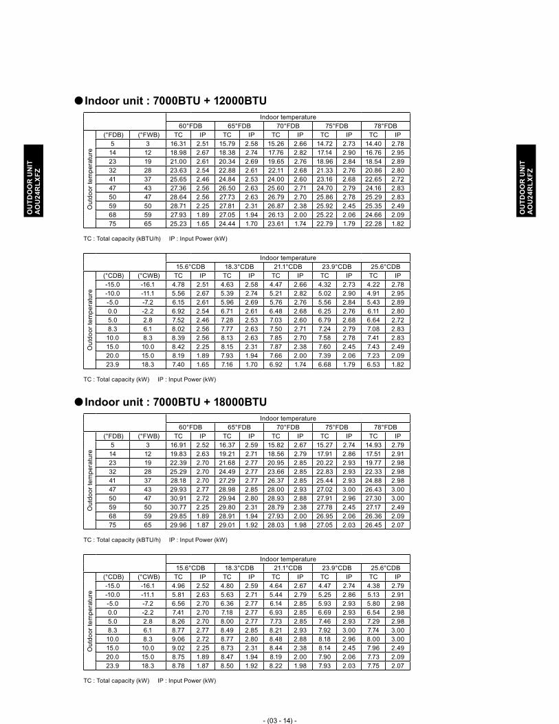
- (03 - 14) -
OU
TDO
OR
UN
ITA
OU
24R
LXFZ
OU
TDO
OR
UN
ITA
OU
24R
LXFZ
Indoor unit : 7000BTU + 12000BTU �Indoor temperature
60°FDB 65°FDB 70°FDB 75°FDB 78°FDB
Out
door
tem
pera
ture
(°FDB) (°FWB) TC IP TC IP TC IP TC IP TC IP5 3 16.31 2.51 15.79 2.58 15.26 2.66 14.72 2.73 14.40 2.78 14 12 18.98 2.67 18.38 2.74 17.76 2.82 17.14 2.90 16.76 2.95 23 19 21.00 2.61 20.34 2.69 19.65 2.76 18.96 2.84 18.54 2.89 32 28 23.63 2.54 22.88 2.61 22.11 2.68 21.33 2.76 20.86 2.80 41 37 25.65 2.46 24.84 2.53 24.00 2.60 23.16 2.68 22.65 2.72 47 43 27.36 2.56 26.50 2.63 25.60 2.71 24.70 2.79 24.16 2.83 50 47 28.64 2.56 27.73 2.63 26.79 2.70 25.86 2.78 25.29 2.83 59 50 28.71 2.25 27.81 2.31 26.87 2.38 25.92 2.45 25.35 2.49 68 59 27.93 1.89 27.05 1.94 26.13 2.00 25.22 2.06 24.66 2.09 75 65 25.23 1.65 24.44 1.70 23.61 1.74 22.79 1.79 22.28 1.82
TC : Total capacity (kBTU/h) IP : Input Power (kW)
Indoor temperature15.6°CDB 18.3°CDB 21.1°CDB 23.9°CDB 25.6°CDB
Out
door
tem
pera
ture
(°CDB) (°CWB) TC IP TC IP TC IP TC IP TC IP-15.0 -16.1 4.78 2.51 4.63 2.58 4.47 2.66 4.32 2.73 4.22 2.78 -10.0 -11.1 5.56 2.67 5.39 2.74 5.21 2.82 5.02 2.90 4.91 2.95 -5.0 -7.2 6.15 2.61 5.96 2.69 5.76 2.76 5.56 2.84 5.43 2.89 0.0 -2.2 6.92 2.54 6.71 2.61 6.48 2.68 6.25 2.76 6.11 2.80 5.0 2.8 7.52 2.46 7.28 2.53 7.03 2.60 6.79 2.68 6.64 2.72 8.3 6.1 8.02 2.56 7.77 2.63 7.50 2.71 7.24 2.79 7.08 2.83 10.0 8.3 8.39 2.56 8.13 2.63 7.85 2.70 7.58 2.78 7.41 2.83 15.0 10.0 8.42 2.25 8.15 2.31 7.87 2.38 7.60 2.45 7.43 2.49 20.0 15.0 8.19 1.89 7.93 1.94 7.66 2.00 7.39 2.06 7.23 2.09 23.9 18.3 7.40 1.65 7.16 1.70 6.92 1.74 6.68 1.79 6.53 1.82
TC : Total capacity (kW) IP : Input Power (kW)
Indoor unit : 7000BTU + 18000BTU �Indoor temperature
60°FDB 65°FDB 70°FDB 75°FDB 78°FDB
Out
door
tem
pera
ture
(°FDB) (°FWB) TC IP TC IP TC IP TC IP TC IP5 3 16.91 2.52 16.37 2.59 15.82 2.67 15.27 2.74 14.93 2.79 14 12 19.83 2.63 19.21 2.71 18.56 2.79 17.91 2.86 17.51 2.91 23 19 22.39 2.70 21.68 2.77 20.95 2.85 20.22 2.93 19.77 2.98 32 28 25.29 2.70 24.49 2.77 23.66 2.85 22.83 2.93 22.33 2.98 41 37 28.18 2.70 27.29 2.77 26.37 2.85 25.44 2.93 24.88 2.98 47 43 29.93 2.77 28.98 2.85 28.00 2.93 27.02 3.00 26.43 3.00 50 47 30.91 2.72 29.94 2.80 28.93 2.88 27.91 2.96 27.30 3.00 59 50 30.77 2.25 29.80 2.31 28.79 2.38 27.78 2.45 27.17 2.49 68 59 29.85 1.89 28.91 1.94 27.93 2.00 26.95 2.06 26.36 2.09 75 65 29.96 1.87 29.01 1.92 28.03 1.98 27.05 2.03 26.45 2.07
TC : Total capacity (kBTU/h) IP : Input Power (kW)
Indoor temperature15.6°CDB 18.3°CDB 21.1°CDB 23.9°CDB 25.6°CDB
Out
door
tem
pera
ture
(°CDB) (°CWB) TC IP TC IP TC IP TC IP TC IP-15.0 -16.1 4.96 2.52 4.80 2.59 4.64 2.67 4.47 2.74 4.38 2.79 -10.0 -11.1 5.81 2.63 5.63 2.71 5.44 2.79 5.25 2.86 5.13 2.91 -5.0 -7.2 6.56 2.70 6.36 2.77 6.14 2.85 5.93 2.93 5.80 2.98 0.0 -2.2 7.41 2.70 7.18 2.77 6.93 2.85 6.69 2.93 6.54 2.98 5.0 2.8 8.26 2.70 8.00 2.77 7.73 2.85 7.46 2.93 7.29 2.98 8.3 6.1 8.77 2.77 8.49 2.85 8.21 2.93 7.92 3.00 7.74 3.00 10.0 8.3 9.06 2.72 8.77 2.80 8.48 2.88 8.18 2.96 8.00 3.00 15.0 10.0 9.02 2.25 8.73 2.31 8.44 2.38 8.14 2.45 7.96 2.49 20.0 15.0 8.75 1.89 8.47 1.94 8.19 2.00 7.90 2.06 7.73 2.09 23.9 18.3 8.78 1.87 8.50 1.92 8.22 1.98 7.93 2.03 7.75 2.07
TC : Total capacity (kW) IP : Input Power (kW)

- (03 - 15) -
OU
TDO
OR
UN
ITA
OU
24R
LXFZ
OU
TDO
OR
UN
ITA
OU
24R
LXFZ
Indoor unit : 9000BTU + 9000BTU �Indoor temperature
60°FDB 65°FDB 70°FDB 75°FDB 78°FDB
Out
door
tem
pera
ture
(°FDB) (°FWB) TC IP TC IP TC IP TC IP TC IP5 3 15.61 2.49 15.12 2.56 14.61 2.64 14.10 2.71 13.79 2.76 14 12 18.36 2.63 17.78 2.71 17.17 2.78 16.57 2.86 16.21 2.91 23 19 20.21 2.59 19.57 2.67 18.91 2.74 18.25 2.82 17.85 2.87 32 28 22.62 2.52 21.91 2.59 21.17 2.66 20.43 2.74 19.98 2.78 41 37 25.05 2.44 24.26 2.51 23.44 2.58 22.62 2.66 22.12 2.70 47 43 26.72 2.54 25.88 2.61 25.00 2.69 24.13 2.77 23.59 2.81 50 47 28.02 2.54 27.14 2.61 26.22 2.68 25.30 2.76 24.74 2.80 59 50 28.33 2.21 27.44 2.27 26.51 2.34 25.58 2.40 25.02 2.44 68 59 25.14 1.85 24.35 1.91 23.52 1.96 22.70 2.02 22.20 2.05 75 65 24.63 1.51 23.86 1.55 23.05 1.60 22.24 1.64 21.75 1.67
TC : Total capacity (kBTU/h) IP : Input Power (kW)
Indoor temperature15.6°CDB 18.3°CDB 21.1°CDB 23.9°CDB 25.6°CDB
Out
door
tem
pera
ture
(°CDB) (°CWB) TC IP TC IP TC IP TC IP TC IP-15.0 -16.1 4.58 2.49 4.43 2.56 4.28 2.64 4.13 2.71 4.04 2.76 -10.0 -11.1 5.38 2.63 5.21 2.71 5.03 2.78 4.86 2.86 4.75 2.91 -5.0 -7.2 5.92 2.59 5.74 2.67 5.54 2.74 5.35 2.82 5.23 2.87 0.0 -2.2 6.63 2.52 6.42 2.59 6.20 2.66 5.99 2.74 5.85 2.78 5.0 2.8 7.34 2.44 7.11 2.51 6.87 2.58 6.63 2.66 6.48 2.70 8.3 6.1 7.83 2.54 7.58 2.61 7.33 2.69 7.07 2.77 6.91 2.81 10.0 8.3 8.21 2.54 7.95 2.61 7.68 2.68 7.42 2.76 7.25 2.80 15.0 10.0 8.30 2.21 8.04 2.27 7.77 2.34 7.50 2.40 7.33 2.44 20.0 15.0 7.37 1.85 7.14 1.91 6.89 1.96 6.65 2.02 6.51 2.05 23.9 18.3 7.22 1.51 6.99 1.55 6.76 1.60 6.52 1.64 6.38 1.67
TC : Total capacity (kW) IP : Input Power (kW)
Indoor unit : 9000BTU + 12000BTU �Indoor temperature
60°FDB 65°FDB 70°FDB 75°FDB 78°FDB
Out
door
tem
pera
ture
(°FDB) (°FWB) TC IP TC IP TC IP TC IP TC IP5 3 15.92 2.52 15.41 2.59 14.89 2.67 14.37 2.74 14.05 2.79 14 12 18.72 2.54 18.13 2.61 17.52 2.69 16.90 2.76 16.53 2.81 23 19 20.73 2.54 20.08 2.61 19.40 2.69 18.72 2.76 18.31 2.81 32 28 23.36 2.51 22.62 2.58 21.86 2.65 21.09 2.73 20.63 2.77 41 37 26.15 2.48 25.33 2.55 24.47 2.62 23.62 2.70 23.10 2.74 47 43 27.89 2.58 27.01 2.65 26.10 2.73 25.19 2.81 24.63 2.85 50 47 28.86 2.55 27.95 2.63 27.01 2.70 26.06 2.78 25.49 2.82 59 50 29.06 2.12 28.14 2.18 27.19 2.24 26.24 2.30 25.66 2.34 68 59 25.42 1.78 24.62 1.83 23.78 1.88 22.95 1.94 22.45 1.97 75 65 25.69 1.66 24.88 1.71 24.04 1.76 23.20 1.81 22.69 1.84
TC : Total capacity (kBTU/h) IP : Input Power (kW)
Indoor temperature15.6°CDB 18.3°CDB 21.1°CDB 23.9°CDB 25.6°CDB
Out
door
tem
pera
ture
(°CDB) (°CWB) TC IP TC IP TC IP TC IP TC IP-15.0 -16.1 4.66 2.52 4.52 2.59 4.36 2.67 4.21 2.74 4.12 2.79 -10.0 -11.1 5.49 2.54 5.31 2.61 5.13 2.69 4.95 2.76 4.85 2.81 -5.0 -7.2 6.08 2.54 5.88 2.61 5.69 2.69 5.49 2.76 5.37 2.81 0.0 -2.2 6.85 2.51 6.63 2.58 6.41 2.65 6.18 2.73 6.05 2.77 5.0 2.8 7.67 2.48 7.42 2.55 7.17 2.62 6.92 2.70 6.77 2.74 8.3 6.1 8.18 2.58 7.92 2.65 7.65 2.73 7.38 2.81 7.22 2.85 10.0 8.3 8.46 2.55 8.19 2.63 7.92 2.70 7.64 2.78 7.47 2.82 15.0 10.0 8.52 2.12 8.25 2.18 7.97 2.24 7.69 2.30 7.52 2.34 20.0 15.0 7.45 1.78 7.21 1.83 6.97 1.88 6.73 1.94 6.58 1.97 23.9 18.3 7.53 1.66 7.29 1.71 7.05 1.76 6.80 1.81 6.65 1.84
TC : Total capacity (kW) IP : Input Power (kW)

- (03 - 16) -
OU
TDO
OR
UN
ITA
OU
24R
LXFZ
OU
TDO
OR
UN
ITA
OU
24R
LXFZ
Indoor unit : 9000BTU + 18000BTU �Indoor temperature
60°FDB 65°FDB 70°FDB 75°FDB 78°FDB
Out
door
tem
pera
ture
(°FDB) (°FWB) TC IP TC IP TC IP TC IP TC IP5 3 17.30 2.52 16.75 2.59 16.19 2.67 15.62 2.74 15.28 2.79 14 12 20.31 2.63 19.67 2.71 19.01 2.79 18.34 2.86 17.94 2.91 23 19 22.96 2.70 22.23 2.78 21.48 2.86 20.73 2.94 20.27 2.99 32 28 26.12 2.70 25.29 2.78 24.44 2.86 23.58 2.94 23.06 2.99 41 37 29.06 2.70 28.14 2.78 27.19 2.86 26.24 2.94 25.66 2.99 47 43 30.99 2.77 30.02 2.85 29.00 2.93 27.99 3.00 27.37 3.00 50 47 32.04 2.73 31.03 2.81 29.98 2.89 28.93 2.97 28.30 3.00 59 50 31.74 2.26 30.74 2.32 29.70 2.39 28.66 2.46 28.03 2.50 68 59 30.93 1.90 29.96 1.95 28.94 2.01 27.93 2.06 27.32 2.10 75 65 31.01 1.87 30.03 1.93 29.02 1.98 28.00 2.04 27.38 2.07
TC : Total capacity (kBTU/h) IP : Input Power (kW)
Indoor temperature15.6°CDB 18.3°CDB 21.1°CDB 23.9°CDB 25.6°CDB
Out
door
tem
pera
ture
(°CDB) (°CWB) TC IP TC IP TC IP TC IP TC IP-15.0 -16.1 5.07 2.52 4.91 2.59 4.74 2.67 4.58 2.74 4.48 2.79 -10.0 -11.1 5.95 2.63 5.77 2.71 5.57 2.79 5.38 2.86 5.26 2.91 -5.0 -7.2 6.73 2.70 6.52 2.78 6.30 2.86 6.07 2.94 5.94 2.99 0.0 -2.2 7.65 2.70 7.41 2.78 7.16 2.86 6.91 2.94 6.76 2.99 5.0 2.8 8.52 2.70 8.25 2.78 7.97 2.86 7.69 2.94 7.52 2.99 8.3 6.1 9.08 2.77 8.80 2.85 8.50 2.93 8.20 3.00 8.02 3.00 10.0 8.3 9.39 2.73 9.09 2.81 8.79 2.89 8.48 2.97 8.29 3.00 15.0 10.0 9.30 2.26 9.01 2.32 8.70 2.39 8.40 2.46 8.21 2.50 20.0 15.0 9.07 1.90 8.78 1.95 8.48 2.01 8.19 2.06 8.01 2.10 23.9 18.3 9.09 1.87 8.80 1.93 8.50 1.98 8.21 2.04 8.03 2.07
TC : Total capacity (kW) IP : Input Power (kW)
Indoor unit : 12000BTU + 12000BTU �Indoor temperature
60°FDB 65°FDB 70°FDB 75°FDB 78°FDB
Out
door
tem
pera
ture
(°FDB) (°FWB) TC IP TC IP TC IP TC IP TC IP5 3 16.62 2.70 16.10 2.78 15.55 2.86 15.01 2.94 14.68 2.99 14 12 19.57 2.70 18.95 2.78 18.31 2.86 17.67 2.94 17.28 2.99 23 19 21.69 2.70 21.00 2.78 20.29 2.86 19.58 2.94 19.15 2.99 32 28 24.46 2.69 23.69 2.76 22.89 2.84 22.09 2.92 21.60 2.97 41 37 27.48 2.67 26.61 2.75 25.71 2.82 24.81 2.90 24.26 2.95 47 43 29.28 2.77 28.36 2.85 27.40 2.93 26.44 3.00 25.86 3.00 50 47 30.51 2.73 29.55 2.81 28.55 2.89 27.55 2.97 26.94 3.00 59 50 30.51 2.26 29.55 2.32 28.55 2.39 27.55 2.46 26.95 2.50 68 59 29.41 1.90 28.48 1.95 27.52 2.01 26.56 2.06 25.97 2.10 75 65 26.96 1.78 26.11 1.83 25.23 1.89 24.35 1.94 23.81 1.97
TC : Total capacity (kBTU/h) IP : Input Power (kW)
Indoor temperature15.6°CDB 18.3°CDB 21.1°CDB 23.9°CDB 25.6°CDB
Out
door
tem
pera
ture
(°CDB) (°CWB) TC IP TC IP TC IP TC IP TC IP-15.0 -16.1 4.87 2.70 4.72 2.78 4.56 2.86 4.40 2.94 4.30 2.99 -10.0 -11.1 5.74 2.70 5.55 2.78 5.37 2.86 5.18 2.94 5.06 2.99 -5.0 -7.2 6.36 2.70 6.16 2.78 5.95 2.86 5.74 2.94 5.61 2.99 0.0 -2.2 7.17 2.69 6.94 2.76 6.71 2.84 6.47 2.92 6.33 2.97 5.0 2.8 8.05 2.67 7.80 2.75 7.53 2.82 7.27 2.90 7.11 2.95 8.3 6.1 8.58 2.77 8.31 2.85 8.03 2.93 7.75 3.00 7.58 3.00 10.0 8.3 8.94 2.73 8.66 2.81 8.37 2.89 8.07 2.97 7.90 3.00 15.0 10.0 8.94 2.26 8.66 2.32 8.37 2.39 8.08 2.46 7.90 2.50 20.0 15.0 8.62 1.90 8.35 1.95 8.07 2.01 7.78 2.06 7.61 2.10 23.9 18.3 7.90 1.78 7.65 1.83 7.39 1.89 7.14 1.94 6.98 1.97
TC : Total capacity (kW) IP : Input Power (kW)

- (03 - 17) -
OU
TDO
OR
UN
ITA
OU
24R
LXFZ
OU
TDO
OR
UN
ITA
OU
24R
LXFZ
Indoor unit : 7000BTU + 7000BTU + 7000BTU �Indoor temperature
60°FDB 65°FDB 70°FDB 75°FDB 78°FDB
Out
door
tem
pera
ture
(°FDB) (°FWB) TC IP TC IP TC IP TC IP TC IP5 3 16.48 2.40 15.96 2.46 15.42 2.54 14.88 2.61 14.55 2.65 14 12 19.17 2.50 18.57 2.57 17.94 2.65 17.31 2.72 16.93 2.77 23 19 21.72 2.61 21.03 2.68 20.32 2.76 19.61 2.84 19.18 2.88 32 28 24.86 2.78 24.08 2.86 23.26 2.94 22.45 3.00 21.96 3.00 41 37 28.16 2.66 27.27 2.73 26.35 2.81 25.43 2.89 24.87 2.94 47 43 30.03 2.68 29.08 2.76 28.10 2.84 27.12 2.92 26.52 2.97 50 47 31.15 2.71 30.17 2.79 29.15 2.87 28.13 2.95 27.51 3.00 59 50 32.65 2.71 31.62 2.79 30.55 2.87 29.48 2.95 28.83 3.00 68 59 29.96 2.10 29.01 2.16 28.03 2.22 27.05 2.28 26.45 2.32 75 65 27.94 1.64 27.05 1.69 26.14 1.74 25.22 1.78 24.67 1.81
TC : Total capacity (kBTU/h) IP : Input Power (kW)
Indoor temperature15.6°CDB 18.3°CDB 21.1°CDB 23.9°CDB 25.6°CDB
Out
door
tem
pera
ture
(°CDB) (°CWB) TC IP TC IP TC IP TC IP TC IP-15.0 -16.1 4.83 2.40 4.68 2.46 4.52 2.54 4.36 2.61 4.26 2.65 -10.0 -11.1 5.62 2.50 5.44 2.57 5.26 2.65 5.07 2.72 4.96 2.77 -5.0 -7.2 6.37 2.61 6.16 2.68 5.96 2.76 5.75 2.84 5.62 2.88 0.0 -2.2 7.29 2.78 7.06 2.86 6.82 2.94 6.58 3.00 6.43 3.00 5.0 2.8 8.25 2.66 7.99 2.73 7.72 2.81 7.45 2.89 7.29 2.94 8.3 6.1 8.80 2.68 8.52 2.76 8.24 2.84 7.95 2.92 7.77 2.97 10.0 8.3 9.13 2.71 8.84 2.79 8.54 2.87 8.24 2.95 8.06 3.00 15.0 10.0 9.57 2.71 9.27 2.79 8.95 2.87 8.64 2.95 8.45 3.00 20.0 15.0 8.78 2.10 8.50 2.16 8.21 2.22 7.93 2.28 7.75 2.32 23.9 18.3 8.19 1.64 7.93 1.69 7.66 1.74 7.39 1.78 7.23 1.81
TC : Total capacity (kW) IP : Input Power (kW)
Indoor unit : 7000BTU + 7000BTU + 9000BTU �Indoor temperature
60°FDB 65°FDB 70°FDB 75°FDB 78°FDB
Out
door
tem
pera
ture
(°FDB) (°FWB) TC IP TC IP TC IP TC IP TC IP5 3 17.47 2.33 16.92 2.40 16.35 2.47 15.78 2.54 15.43 2.58 14 12 20.33 2.45 19.69 2.52 19.02 2.59 18.36 2.67 17.95 2.71 23 19 23.03 2.54 22.30 2.61 21.55 2.69 20.80 2.76 20.34 2.81 32 28 26.37 2.71 25.54 2.79 24.67 2.87 23.81 2.95 23.28 3.00 41 37 29.86 2.71 28.92 2.79 27.94 2.87 26.96 2.95 26.37 3.00 47 43 31.85 2.77 30.84 2.85 29.80 2.93 28.76 3.00 28.12 3.00 50 47 33.04 2.71 32.00 2.79 30.91 2.87 29.83 2.95 29.17 3.00 59 50 34.63 2.67 33.53 2.75 32.40 2.83 31.27 2.91 30.58 2.96 68 59 31.77 2.03 30.77 2.09 29.72 2.15 28.68 2.21 28.05 2.24 75 65 29.61 1.70 28.68 1.75 27.71 1.80 26.74 1.85 26.15 1.88
TC : Total capacity (kBTU/h) IP : Input Power (kW)
Indoor temperature15.6°CDB 18.3°CDB 21.1°CDB 23.9°CDB 25.6°CDB
Out
door
tem
pera
ture
(°CDB) (°CWB) TC IP TC IP TC IP TC IP TC IP-15.0 -16.1 5.12 2.33 4.96 2.40 4.79 2.47 4.62 2.54 4.52 2.58 -10.0 -11.1 5.96 2.45 5.77 2.52 5.58 2.59 5.38 2.67 5.26 2.71 -5.0 -7.2 6.75 2.54 6.54 2.61 6.32 2.69 6.10 2.76 5.96 2.81 0.0 -2.2 7.73 2.71 7.48 2.79 7.23 2.87 6.98 2.95 6.82 3.00 5.0 2.8 8.75 2.71 8.48 2.79 8.19 2.87 7.90 2.95 7.73 3.00 8.3 6.1 9.33 2.77 9.04 2.85 8.73 2.93 8.43 3.00 8.24 3.00 10.0 8.3 9.68 2.71 9.38 2.79 9.06 2.87 8.74 2.95 8.55 3.00 15.0 10.0 10.15 2.67 9.83 2.75 9.50 2.83 9.16 2.91 8.96 2.96 20.0 15.0 9.31 2.03 9.02 2.09 8.71 2.15 8.41 2.21 8.22 2.24 23.9 18.3 8.68 1.70 8.40 1.75 8.12 1.80 7.84 1.85 7.66 1.88
TC : Total capacity (kW) IP : Input Power (kW)

- (03 - 18) -
OU
TDO
OR
UN
ITA
OU
24R
LXFZ
OU
TDO
OR
UN
ITA
OU
24R
LXFZ
Indoor unit : 7000BTU + 7000BTU + 12000BTU �Indoor temperature
60°FDB 65°FDB 70°FDB 75°FDB 78°FDB
Out
door
tem
pera
ture
(°FDB) (°FWB) TC IP TC IP TC IP TC IP TC IP5 3 17.59 2.28 17.03 2.34 16.46 2.41 15.88 2.48 15.53 2.52 14 12 20.47 2.39 19.82 2.46 19.15 2.53 18.48 2.60 18.07 2.65 23 19 23.19 2.48 22.45 2.55 21.70 2.63 20.94 2.70 20.47 2.74 32 28 26.54 2.68 25.71 2.76 24.84 2.84 23.97 2.92 23.44 2.97 41 37 30.06 2.68 29.11 2.76 28.13 2.84 27.14 2.92 26.55 2.97 47 43 32.06 2.70 31.05 2.78 30.00 2.86 28.95 2.94 28.31 2.99 50 47 33.26 2.68 32.21 2.76 31.12 2.84 30.03 2.92 29.37 2.97 59 50 34.86 2.60 33.76 2.67 32.62 2.75 31.48 2.82 30.78 2.87 68 59 31.98 1.98 30.97 2.04 29.92 2.10 28.88 2.15 28.24 2.19 75 65 32.45 1.77 31.43 1.82 30.36 1.87 29.30 1.93 28.66 1.96
TC : Total capacity (kBTU/h) IP : Input Power (kW)
Indoor temperature15.6°CDB 18.3°CDB 21.1°CDB 23.9°CDB 25.6°CDB
Out
door
tem
pera
ture
(°CDB) (°CWB) TC IP TC IP TC IP TC IP TC IP-15.0 -16.1 5.16 2.28 4.99 2.34 4.82 2.41 4.65 2.48 4.55 2.52 -10.0 -11.1 6.00 2.39 5.81 2.46 5.61 2.53 5.42 2.60 5.30 2.65 -5.0 -7.2 6.80 2.48 6.58 2.55 6.36 2.63 6.14 2.70 6.00 2.74 0.0 -2.2 7.78 2.68 7.53 2.76 7.28 2.84 7.02 2.92 6.87 2.97 5.0 2.8 8.81 2.68 8.53 2.76 8.24 2.84 7.96 2.92 7.78 2.97 8.3 6.1 9.40 2.70 9.10 2.78 8.79 2.86 8.48 2.94 8.30 2.99 10.0 8.3 9.75 2.68 9.44 2.76 9.12 2.84 8.80 2.92 8.61 2.97 15.0 10.0 10.22 2.60 9.89 2.67 9.56 2.75 9.23 2.82 9.02 2.87 20.0 15.0 9.37 1.98 9.08 2.04 8.77 2.10 8.46 2.15 8.28 2.19 23.9 18.3 9.51 1.77 9.21 1.82 8.90 1.87 8.59 1.93 8.40 1.96
TC : Total capacity (kW) IP : Input Power (kW)
Indoor unit : 7000BTU + 9000BTU + 9000BTU �Indoor temperature
60°FDB 65°FDB 70°FDB 75°FDB 78°FDB
Out
door
tem
pera
ture
(°FDB) (°FWB) TC IP TC IP TC IP TC IP TC IP5 3 17.59 2.33 17.03 2.40 16.46 2.47 15.88 2.54 15.53 2.58 14 12 20.47 2.45 19.82 2.52 19.15 2.59 18.48 2.67 18.07 2.71 23 19 23.19 2.54 22.45 2.61 21.70 2.69 20.94 2.76 20.47 2.81 32 28 26.54 2.71 25.71 2.79 24.84 2.87 23.97 2.95 23.44 3.00 41 37 30.06 2.71 29.11 2.79 28.13 2.87 27.14 2.95 26.55 3.00 47 43 32.06 2.77 31.05 2.85 30.00 2.93 28.95 3.00 28.31 3.00 50 47 33.26 2.71 32.21 2.79 31.12 2.87 30.03 2.95 29.37 3.00 59 50 34.86 2.67 33.76 2.75 32.62 2.83 31.48 2.91 30.78 2.96 68 59 31.98 2.03 30.97 2.09 29.92 2.15 28.88 2.21 28.24 2.24 75 65 32.09 1.77 31.08 1.82 30.03 1.87 28.98 1.92 28.34 1.96
TC : Total capacity (kBTU/h) IP : Input Power (kW)
Indoor temperature15.6°CDB 18.3°CDB 21.1°CDB 23.9°CDB 25.6°CDB
Out
door
tem
pera
ture
(°CDB) (°CWB) TC IP TC IP TC IP TC IP TC IP-15.0 -16.1 5.16 2.33 4.99 2.40 4.82 2.47 4.65 2.54 4.55 2.58 -10.0 -11.1 6.00 2.45 5.81 2.52 5.61 2.59 5.42 2.67 5.30 2.71 -5.0 -7.2 6.80 2.54 6.58 2.61 6.36 2.69 6.14 2.76 6.00 2.81 0.0 -2.2 7.78 2.71 7.53 2.79 7.28 2.87 7.02 2.95 6.87 3.00 5.0 2.8 8.81 2.71 8.53 2.79 8.24 2.87 7.96 2.95 7.78 3.00 8.3 6.1 9.40 2.77 9.10 2.85 8.79 2.93 8.48 3.00 8.30 3.00 10.0 8.3 9.75 2.71 9.44 2.79 9.12 2.87 8.80 2.95 8.61 3.00 15.0 10.0 10.22 2.67 9.89 2.75 9.56 2.83 9.23 2.91 9.02 2.96 20.0 15.0 9.37 2.03 9.08 2.09 8.77 2.15 8.46 2.21 8.28 2.24 23.9 18.3 9.41 1.77 9.11 1.82 8.80 1.87 8.49 1.92 8.31 1.96
TC : Total capacity (kW) IP : Input Power (kW)

- (03 - 19) -
OU
TDO
OR
UN
ITA
OU
24R
LXFZ
OU
TDO
OR
UN
ITA
OU
24R
LXFZ
Indoor unit : 9000BTU + 9000BTU + 9000BTU �Indoor temperature
60°FDB 65°FDB 70°FDB 75°FDB 78°FDB
Out
door
tem
pera
ture
(°FDB) (°FWB) TC IP TC IP TC IP TC IP TC IP5 3 17.59 2.33 17.03 2.40 16.46 2.47 15.88 2.54 15.53 2.58 14 12 20.47 2.45 19.82 2.52 19.15 2.59 18.48 2.67 18.07 2.71 23 19 23.19 2.54 22.45 2.61 21.70 2.69 20.94 2.76 20.47 2.81 32 28 26.54 2.71 25.71 2.79 24.84 2.87 23.97 2.95 23.44 3.00 41 37 30.06 2.71 29.11 2.79 28.13 2.87 27.14 2.95 26.55 3.00 47 43 32.06 2.77 31.05 2.85 30.00 2.93 28.95 3.00 28.31 3.00 50 47 33.26 2.71 32.21 2.79 31.12 2.87 30.03 2.95 29.37 3.00 59 50 34.86 2.67 33.76 2.75 32.62 2.83 31.48 2.91 30.78 2.96 68 59 31.98 2.03 30.97 2.09 29.92 2.15 28.88 2.21 28.24 2.24 75 65 32.09 1.78 31.07 1.83 30.02 1.88 28.97 1.93 28.33 1.96
TC : Total capacity (kBTU/h) IP : Input Power (kW)
Indoor temperature15.6°CDB 18.3°CDB 21.1°CDB 23.9°CDB 25.6°CDB
Out
door
tem
pera
ture
(°CDB) (°CWB) TC IP TC IP TC IP TC IP TC IP-15.0 -16.1 5.16 2.33 4.99 2.40 4.82 2.47 4.65 2.54 4.55 2.58 -10.0 -11.1 6.00 2.45 5.81 2.52 5.61 2.59 5.42 2.67 5.30 2.71 -5.0 -7.2 6.80 2.54 6.58 2.61 6.36 2.69 6.14 2.76 6.00 2.81 0.0 -2.2 7.78 2.71 7.53 2.79 7.28 2.87 7.02 2.95 6.87 3.00 5.0 2.8 8.81 2.71 8.53 2.79 8.24 2.87 7.96 2.95 7.78 3.00 8.3 6.1 9.40 2.77 9.10 2.85 8.79 2.93 8.48 3.00 8.30 3.00 10.0 8.3 9.75 2.71 9.44 2.79 9.12 2.87 8.80 2.95 8.61 3.00 15.0 10.0 10.22 2.67 9.89 2.75 9.56 2.83 9.23 2.91 9.02 2.96 20.0 15.0 9.37 2.03 9.08 2.09 8.77 2.15 8.46 2.21 8.28 2.24 23.9 18.3 9.40 1.78 9.11 1.83 8.80 1.88 8.49 1.93 8.30 1.96
TC : Total capacity (kW) IP : Input Power (kW)

- (03 - 20) -
OU
TDO
OR
UN
ITA
OU
24R
LXFZ
OU
TDO
OR
UN
ITA
OU
24R
LXFZ
CAPACITY COMPENSATION RATE FOR PIPE LENGTH 6. AND HEIGHT DEFFERENCE
INDOOR UNIT: 7000BTU (AOU24RLXFZ) �
Height difference H
�1 Indoor unit is upper than outdoor unit. �2 Indoor unit is under than outdoor unit.
Indoor unit
Indoor unit
Connection pipe
Outdoor unit
Outdoor unit
Connection pipe
COOLING
Pipe length
5m 7.5m 10m 15m 20m 25m
16ft. 25ft. 33ft. 49ft. 66ft. 82ft.
Height difference
H
�1 Indoor unit is upper than
outdoor unit.
15m 49ft. - - - 0.956 0.942 0.928
10m 33ft. - - 0.977 0.963 0.950 0.936
7.5m 25ft. - 0.988 0.981 0.967 0.953 0.940
5m 16ft. 0.995 0.992 0.985 0.971 0.957 0.943
0m 0ft. 1.003 1.000 0.993 0.979 0.965 0.951
�2 Indoor unit is under than outdoor unit
-5m -16ft. 1.003 1.000 0.993 0.979 0.965 0.951
-7.5m -25ft. - 1.000 0.993 0.979 0.965 0.951
-10m -33ft. - - 0.993 0.979 0.965 0.951
-15m -49ft. - - - 0.979 0.965 0.951
HEATING
Pipe length
5m 7.5m 10m 15m 20m 25m
16ft. 25ft. 33ft. 49ft. 66ft. 82ft.
Height difference
H
�1 Indoor unit is upper than
outdoor unit.
15m 49ft. - - - 0.977 0.958 0.939
10m 33ft. - - 0.993 0.977 0.958 0.939
7.5m 25ft. - 1.000 0.993 0.977 0.958 0.939
5m 16ft. 0.990 1.000 0.993 0.977 0.958 0.939
0m 0ft. 0.990 1.000 0.993 0.977 0.958 0.939
�2 Indoor unit is under than outdoor unit
-5m -16ft. 0.985 0.995 0.988 0.972 0.953 0.934
-7.5m -25ft. - 0.993 0.986 0.970 0.951 0.932
-10m -33ft. - - 0.983 0.967 0.948 0.930
-15m -49ft. - - - 0.962 0.944 0.925

- (03 - 21) -
OU
TDO
OR
UN
ITA
OU
24R
LXFZ
OU
TDO
OR
UN
ITA
OU
24R
LXFZ
INDOOR UNIT: 9000BTU (AOU24RLXFZ) �
Height difference H
�1 Indoor unit is upper than outdoor unit. �2 Indoor unit is under than outdoor unit.
Indoor unit
Indoor unit
Connection pipe
Outdoor unit
Outdoor unit
Connection pipe
COOLING
Pipe length
5m 7.5m 10m 15m 20m 25m
16ft. 25ft. 33ft. 49ft. 66ft. 82ft.
Height difference
H
�1 Indoor unit is upper than
outdoor unit.
15m 49ft. - - - 0.956 0.942 0.928
10m 33ft. - - 0.977 0.963 0.950 0.936
7.5m 25ft. - 0.988 0.981 0.967 0.953 0.940
5m 16ft. 0.999 0.992 0.985 0.971 0.957 0.943
0m 0ft. 1.007 1.000 0.993 0.979 0.965 0.951
�2 Indoor unit is under than outdoor unit
-5m -16ft. 1.007 1.000 0.993 0.979 0.965 0.951
-7.5m -25ft. - 1.000 0.993 0.979 0.965 0.951
-10m -33ft. - - 0.993 0.979 0.965 0.951
-15m -49ft. - - - 0.979 0.965 0.951
HEATING
Pipe length
5m 7.5m 10m 15m 20m 25m
16ft. 25ft. 33ft. 49ft. 66ft. 82ft.
Height difference
H
�1 Indoor unit is upper than
outdoor unit.
15m 49ft. - - - 0.977 0.958 0.939
10m 33ft. - - 0.993 0.977 0.958 0.939
7.5m 25ft. - 1.000 0.993 0.977 0.958 0.939
5m 16ft. 0.993 1.000 0.993 0.977 0.958 0.939
0m 0ft. 0.993 1.000 0.993 0.977 0.958 0.939
�2 Indoor unit is under than outdoor unit
-5m -16ft. 0.988 0.995 0.988 0.972 0.953 0.934
-7.5m -25ft. - 0.993 0.986 0.970 0.951 0.932
-10m -33ft. - - 0.983 0.967 0.948 0.930
-15m -49ft. - - - 0.962 0.944 0.925

- (03 - 22) -
OU
TDO
OR
UN
ITA
OU
24R
LXFZ
OU
TDO
OR
UN
ITA
OU
24R
LXFZ
INDOOR UNIT: 12000BTU (AOU24RLXFZ) �
Height difference H
�1 Indoor unit is upper than outdoor unit. �2 Indoor unit is under than outdoor unit.
Indoor unit
Indoor unit
Connection pipe
Outdoor unit
Outdoor unit
Connection pipe
COOLING
Pipe length
5m 7.5m 10m 15m 20m 25m
16ft. 25ft. 33ft. 49ft. 66ft. 82ft.
Height difference
H
�1 Indoor unit is upper than
outdoor unit.
15m 49ft. - - - 0.933 0.899 0.859
10m 33ft. - - 0.970 0.940 0.906 0.866
7.5m 25ft. - 0.988 0.974 0.944 0.910 0.869
5m 16ft. 1.006 0.992 0.978 0.948 0.913 0.873
0m 0ft. 1.014 1.000 0.986 0.956 0.921 0.880
�2 Indoor unit is under than outdoor unit
-5m -16ft. 1.014 1.000 0.986 0.956 0.921 0.880
-7.5m -25ft. - 1.000 0.986 0.956 0.921 0.880
-10m -33ft. - - 0.986 0.956 0.921 0.880
-15m -49ft. - - - 0.956 0.921 0.880
HEATING
Pipe length
5m 7.5m 10m 15m 20m 25m
16ft. 25ft. 33ft. 49ft. 66ft. 82ft.
Height difference
H
�1 Indoor unit is upper than
outdoor unit.
15m 49ft. - - - 0.975 0.957 0.940
10m 33ft. - - 0.990 0.975 0.957 0.940
7.5m 25ft. - 1.000 0.990 0.975 0.957 0.940
5m 16ft. 0.995 1.000 0.990 0.975 0.957 0.940
0m 0ft. 0.995 1.000 0.990 0.975 0.957 0.940
�2 Indoor unit is under than outdoor unit
-5m -16ft. 0.990 0.995 0.985 0.970 0.952 0.936
-7.5m -25ft. - 0.993 0.983 0.968 0.950 0.934
-10m -33ft. - - 0.980 0.965 0.947 0.931
-15m -49ft. - - - 0.960 0.943 0.926

- (03 - 23) -
OU
TDO
OR
UN
ITA
OU
24R
LXFZ
OU
TDO
OR
UN
ITA
OU
24R
LXFZ
INDOOR UNIT: 18000BTU (AOU24RLXFZ) �
Height difference H
�1 Indoor unit is upper than outdoor unit. �2 Indoor unit is under than outdoor unit.
Indoor unit
Indoor unit
Connection pipe
Outdoor unit
Outdoor unit
Connection pipe
COOLING
Pipe length
5m 7.5m 10m 15m 20m 25m
16ft. 25ft. 33ft. 49ft. 66ft. 82ft.
Height difference
H
�1 Indoor unit is upper than
outdoor unit.
15m 49ft. - - - 0.977 0.968 0.953
10m 33ft. - - 0.986 0.985 0.976 0.960
7.5m 25ft. - 0.988 0.990 0.989 0.980 0.964
5m 16ft. 0.989 0.992 0.994 0.993 0.984 0.968
0m 0ft. 0.997 1.000 1.002 1.002 0.992 0.976
�2 Indoor unit is under than outdoor unit
-5m -16ft. 0.997 1.000 1.002 1.002 0.992 0.976
-7.5m -25ft. - 1.000 1.002 1.002 0.992 0.976
-10m -33ft. - - 1.002 1.002 0.992 0.976
-15m -49ft. - - - 1.002 0.992 0.976
HEATING
Pipe length
5m 7.5m 10m 15m 20m 25m
16ft. 25ft. 33ft. 49ft. 66ft. 82ft.
Height difference
H
�1 Indoor unit is upper than
outdoor unit.
15m 49ft. - - - 0.964 0.939 0.913
10m 33ft. - - 0.988 0.964 0.939 0.913
7.5m 25ft. - 1.000 0.988 0.964 0.939 0.913
5m 16ft. 1.008 1.000 0.988 0.964 0.939 0.913
0m 0ft. 1.008 1.000 0.988 0.964 0.939 0.913
�2 Indoor unit is under than outdoor unit
-5m -16ft. 1.003 0.995 0.983 0.959 0.934 0.908
-7.5m -25ft. - 0.993 0.981 0.957 0.932 0.907
-10m -33ft. - - 0.978 0.954 0.930 0.904
-15m -49ft. - - - 0.950 0.925 0.899

- (03 - 24) -
OU
TDO
OR
UN
ITA
OU
24R
LXFZ
OU
TDO
OR
UN
ITA
OU
24R
LXFZ
ADDITIONAL CHARGE CALCULATION7. MODEL � : AOU24RLXFZ
Refrigerant charge �
Refrigerant type R410A
Refrigerant amountlbs. oz. 4 lbs. 14 oz.
g 2200
Total pipe lengthft. 98 or less 131 164 (MAX)
0.21 oz./ft.
20g/m
m 30 or less 40 50 (MAX)
Additional chargelbs. oz. 0 7.1 oz. 14.1 oz.
g 0 200 400
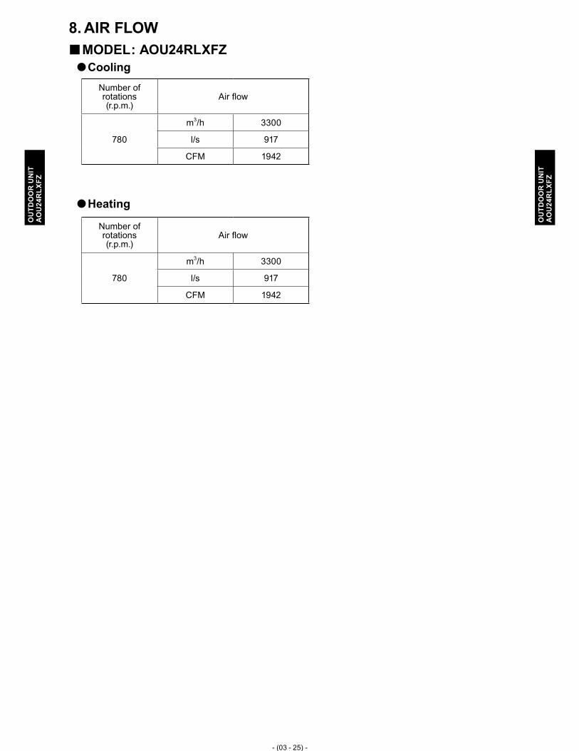
- (03 - 25) -
OU
TDO
OR
UN
ITA
OU
24R
LXFZ
OU
TDO
OR
UN
ITA
OU
24R
LXFZ
AIR FLOW8. MODEL � : AOU24RLXFZCooling �
Heating �
Number of rotations (r.p.m.)
Air flow
780
m3/h 3300
l/s 917
CFM 1942
Number of rotations (r.p.m.)
Air flow
780
m3/h 3300
l/s 917
CFM 1942

- (03 - 26) -
OU
TDO
OR
UN
ITA
OU
24R
LXFZ
OU
TDO
OR
UN
ITA
OU
24R
LXFZ
OPERATION NOISE9. NOISE LEVEL CURVE9-1.
MODEL � : AOU24RLXFZHeating �Cooling �
Oct
ave
band
sou
nd p
ress
ure
leve
l, dB
:(0dB
=0.0
002μ
bar)
80
70
60
50
40
30
20
10
0
NC-65
NC-60
NC-55
NC-50
NC-45
NC-40
NC-35
NC-30
NC-25
NC-20
NC-15O
ctav
e ba
nd s
ound
pre
ssur
e le
vel,
dB:(0
dB=0
.000
2μba
r)
80
70
60
50
40
30
20
10
0
NC-65
NC-60
NC-55
NC-50
NC-45
NC-40
NC-35
NC-30
NC-25
NC-20
NC-15
Octave band center frequency,Hz
63 125 250 500 1,000 2,000 4,000 8,000
Octave band center frequency,Hz
63 125 250 500 1,000 2,000 4,000 8,000

- (03 - 27) -
OU
TDO
OR
UN
ITA
OU
24R
LXFZ
OU
TDO
OR
UN
ITA
OU
24R
LXFZ
SOUND LEVEL CHECK POINT9-2.
3ft. 3-3/8in. (1m)

- (03 - 28) -
OU
TDO
OR
UN
ITA
OU
24R
LXFZ
OU
TDO
OR
UN
ITA
OU
24R
LXFZ
ELECTRIC CHARACTERISTICS10.
Model name AOU24RLXFZ
Power supply Voltage V 208 / 230 ~Frequency Hz 60
Max. operation current A 13.7 / 13.7Starting current A 9.0
*1) Wiring spec.
Main fuse (Circuit breaker) current
A 25.0
Power cable AWG 10*2) Limited wiring length ft. 64 / 71
*1) Wiring spec. : selected sample (Selected based on Japan Electrotechnical Standard and Codes Committee E0005)
*2) Limited wiring length : This is the wiring length in case voltage descent is less than 2%.When the wiring length become long, please select the wiring of a more larger diameter.

- (03 - 29) -
OU
TDO
OR
UN
ITA
OU
24R
LXFZ
OU
TDO
OR
UN
ITA
OU
24R
LXFZ
SAFETY DEVICES11.
Protection formModel
AOU24RLXFZ
Circuit protection
Current fuse (MAIN PCB)15A 250V
10A 250V
Current fuse (NEAR THE TERMINAL)
20A 250V
Fan motor protection Temperature Thermistor 266 ± 36°F OFF 212 ± 36°F ON
130 ± 20°C OFF 100 ± 20°C ON
Compressor protection Temperature Thermistor230±4°F OFF 176±4°F ON
110±2°C OFF 80±2°C ON
Refrigerant circuit protection Pressure switch (1)609±15PSI OFF 464±22PSI ON
4.2±0.1MPa OFF 3.2±0.15MPa ON
*Pressure switch (2) : For control device

- (03 - 30) -
OU
TDO
OR
UN
ITA
OU
24R
LXFZ
OU
TDO
OR
UN
ITA
OU
24R
LXFZ
INSTALLATION PRECAUTIONS12. OUTDOOR UNIT INSTALLATION PRECAUTIONS12-1.
Note: The information listed below are general precautions. Some models also include items that do not apply.
PLACES WHERE USE PROHIBITED �Places where there is the danger of combustible gas leakage •Places where sulfur gas, chlorine gas, acid, alkali, or other matter which effects equipment is •generatedPlaces not affected by heat radiation from other heat sources •Places where the air is not stagnant •Places where machinery which generates high frequencies is used •Ocean beaches and other areas where there is a lot of salt •Installation in vehicles, ships, and other conveyances •Factory, etc. where voltage fluctuations are large •
POINTS TO REMEMBER WHEN INSTALLING �The set shall be installed at a place which can withstand the weight and vibration of the outdoor (1) unitTo allow maintenance after refrigerant piping, drain piping, and electric wiring connection and (2) installation, provide an installation service space.
*Installation service space is shown on " INSTALLATION PLACE ".Be careful when installing the set at the following places.(3)
[Installation precautions]
Contents Countermeasures (Reference)When installed near adjacent houses
Perform installation work so that operating sound does not disturb the neighbors.
Install a soundproof barrier(1)
Change the installation site(2)
When there is the possibility of strong wind
If the outdoor unit is exposed to strong wind, capacity may (1) drop, frost may form during heating, and operation may be stopped by high pressure rise. In addition, when a very strong wind blows, the fan may be damaged.
When a very strong wind blows, there is the possibility (2) of the outdoor unit being toppled over if held only by foundation bolts
Install with the outlet side (1) Keep a sufficient distance away from a facing wall or fence.
Make the outlet direction and (2) wind direction perpendicular.
Fasten the outdoor unit using (3) toppling prevention hardware (procured at the site).
When snow accumulates
If the outdoor unit is covered by accumulated snow, it may not be able to operate.
Make the foundation as high as (1) possible.
Perform snow prevention work.(2) When installing the inverter type
It may generate noise in TV sets, stereos and PCs. The inverter type should be (1) installed at a sufficient distance from these equipments.

4. OUTDOOR UNIT (4 ROOMS TYPE)
MULTI TYPE :AOU36RLXFZ
DTR_AO076E_032011.04.15

OU
TDO
OR
UN
ITA
OU
36R
LXFZ
OU
TDO
OR
UN
ITA
OU
36R
LXFZ
CONTENTS
4. OUTDOOR UNIT (4 ROOMS TYPE)
1. SPECIFICATIONS ........................................................................................... 04 - 01
2. DIMENSIONS ...................................................................................................... 04 - 02
3. REFRIGERANT CIRCUIT .......................................................................... 04 - 03
4. WIRING DIAGRAMS ..................................................................................... 04 - 04
5. CAPACITY TABLE .......................................................................................... 04 - 055-1. COMBINATIONS ............................................................................................... 04 - 05
5-2. COOLING CAPACITY ...................................................................................... 04 - 07
5-3. HEATING CAPACITY ....................................................................................... 04 - 19
6. CAPACITY COMPENSATION RATE FOR PIPE LENGTH AND HEIGHT DEFFERENCE ................................................................ 04 - 31
7. ADDITIONAL CHARGE CALCULATION ...................................... 04 - 36
8. AIR FLOW ............................................................................................................. 04 - 37
9. OPERATION NOISE ...................................................................................... 04 - 389-1. NOISE LEVEL CURVE ..................................................................................... 04 - 38
9-2. SOUND LEVEL CHECK POINT ..................................................................... 04 - 39
10. ELECTRIC CHARACTERISTICS ........................................................ 04 - 40
11. SAFETY DEVICES .......................................................................................... 04 - 41
12. OPTIONAL PARTS ......................................................................................... 04 - 42
13. INSTALLATION PRECAUTIONS ......................................................... 04 - 4413-1. OUTDOOR UNIT INSTALLATION PRECAUTIONS .................................... 04 - 44

- (04 - 01) -
OU
TDO
OR
UN
ITA
OU
36R
LXFZ
OU
TDO
OR
UN
ITA
OU
36R
LXFZ
SPECIFICATIONS1. Model name AOU36RLXFZPower source 1Ø 208/230V 60HzAvailable voltage range 187-264V
Connectable indoor unitNumber 2* to 4
Total capacity range 27,000 to 39,000 Btu/h
Combination of indoor unit Non-DuctASU9RLF x 4
DuctARU9RLF x 4 Mix
Capacity
CoolingRated
Btu/h 35,200 33,800 34,400kW 10.30 9.90 10.08
Min. - Max.Btu/h 11,000-36,000 11,000-36,000 11,000-36,000kW 3.2 - 10.5 3.2 - 10.5 3.2 - 10.5
HeatingRated
Btu/h 36,400 36,400 36,400kW 10.68 10.68 10.68
Min. - Max.Btu/h 11,000-42,000 11,000-42,000 11,000-42,000kW 3.2 - 12.3 3.2 - 12.3 3.2 - 12.3
Input powerCooling
Rated
kW
4.00 4.15 4.07 Max. 4.10 4.38 4.24
HeatingRated 3.00 3.45 3.21 Max. 3.70 3.85 3.78
CurrentCooling
Rated
A
17.5 18.1 17.8 Max. 18.0 19.1 18.6
HeatingRated 13.1 15.1 14.1 Max. 16.2 16.8 16.5
EER Cooling Rated Btu/W 8.80 8.10 8.45 SEER �1 Cooling Rated - 16.00 14.50 15.25 COP Heating Rated W/W 3.56 3.08 3.32HSPF �1 Heating Rated - 9.40 8.70 9.05 Starting current A 15.1
Fan
Type × Q'ty Propeller ×1AirFlow rate
CoolingCFM(m3/h)
2,119 ( 3,600 )Heating 2,237 ( 3,800 )
MotorType × Quantity DC motor ×1Output W 100
Sound pressure levelCooling Rated
dB(A)53
Heating Rated 55
Heat exchanger
Dimension (H x W x D) in.(mm) 31-13/32 × 35-7/16 × 1-7/16 (798×900×36.38)Fin pitch FPI 20Rows × Stages 2 × 38 Pipe type (Material) Grooved H-pin (Copper)
FinType (Material) Corrugate (Aluminum)Surface treatment Pre-coated
CompressorType × Quantity DC TWIN ROTARY ×1Motor output W 1,300
Refrigerant Type R410ACharge lbs.(g) 7lbs. 4oz. (3,300)
Refrigerant oil Type POE
EnclosureMaterial Painted galvanized steel
Color BEIGE ( Approximate color of MUNSELL 10YR 7.5/1.0NN )
DimensionsNet
(H x W x D) in.(mm)32-11/16 × 35-7/16 × 13 (830 × 900 × 330)
Gross 38-3/16 × 41-11/32 × 17-17/32 (970 × 1,050 × 445)
WeightNet
lbs.(kg)149 (68)
Gross 165 (75)
Connection pipe
SizeLiquid
in.(mm)1/4 (6.35) x 4
Gas 3/8(9.52) x 3 + 1/2(12.7) x 1Method FlarePre-charge length (Total)
ft.(m)
164 (50)**Max. length (Total) 230 (70)Max. length (Each) 82 (25)Min. length (Total) 66 (20)Min. length (Each) 16 (5)Max. height difference betweenOutdoor Unit and each Indoor Units. 49 (15)
Max. height difference betweenIndoor Units. 33 (10)
Operation rangeCooling
°F(°C)32 to 115 ( 0 to 46 ) ***
Heating 14 to 75 (-10 to 24)
Note:1. Specifications are based on the following conditions.
Power source of specifications : 230VPipe length : 24.6ft.(7.5m), Height difference : 0 ft.(0m) [Outdoor unit - Indoor unit]Cooling: Indoor temperature of 80°F(26.7°C)DB / 67°F(19.4°C)WB, and outdoor temperature of 95°F(35°C)DB/75°F(23.9°C)WB.Heating: Indoor temperature of 70°F(21.1°C)DB / 60°F(15.6°C)WB, and outdoor temperature of 47°F(8.3°C)DB/43°F(6.1°C)WB.�1: Test conditions are besed on AHRI 210/240.
2. *, **, *** If AOU36RLXFZ is paired with two 18,000 BTU indoor units, you have to purchase optional parts K9FZ1818 kit. In this case, pre-charge length is 66ft.(20m), the cooling operation range is limited to 50°F(10°C) to 115°F(46°C), heating operation range remains unchanged at 14°F(-10°C) to 75°F(24°C).
3. For other combination, refer to the combination table. 4. The protective function might work when using it outside the operation range.

- (04 - 02) -
OU
TDO
OR
UN
ITA
OU
36R
LXFZ
OU
TDO
OR
UN
ITA
OU
36R
LXFZ
DIMENSIONS2. MODEL � : AOU36RLXFZ
[Unit: inch (mm)]
INSTALLATION PLACE �[Unit: inch (mm)]
25-5/8 (600)or more
3-15/16 (100)or more
*23-
5/8
(600
)
11-13/16 (300)or more
*3-15/16 (100)
9-27/32 (250) or more
(Service space)
9-27/32 (250)or more
9-27/32 (250)or more 11-13/16 (300)
or more
When there are obstacles at the back or front sides.
When there are obstacles at the back, side(s), and top.
When there are obstacles at the back, side with the installation of more than one unit.
* If the space is larger that is stated, the condition will be the same as that are no obstacles.
Top view
Front view
Bottom view
Side view
35-7/16 (900)
32-1
1/16
(830
)
13/1
6 (2
1)
14-7
/8 (3
70)
11/3
2(9
)
1-9/16(40)
1-7/32(31)
15/32(12)13 (330)
15-3/4 (400)
25-19/32 (650)
4-Ø15/32 (Ø12)
Drain cap mounting places Drain pipe mounting places
3/16 (5)
2-1/
4 (5
7)
3-11
/16
(94)
4-1/
2 (1
14)
13-1
5/32
(114
x3=3
42)
15/32 (12)
1-5/8 (41)

- (04 - 03) -
OU
TDO
OR
UN
ITA
OU
36R
LXFZ
OU
TDO
OR
UN
ITA
OU
36R
LXFZ
REFRIGERANT CIRCUIT3. MODEL � : AOU36RLXFZ
HEAT EXCHANGER
HEAT EXCHANGERHEAT EXCHANGERHEAT EXCHANGERHEAT EXCHANGER
CHARGINGVALVE
CHARGINGVALVE
CHARGINGVALVE
CHARGINGVALVE
Outdoor unit
Indoor unit A Indoor unit B Indoor unit C Indoor unit D
OIL BACKCAPILLARY
PRESSURE SWITCH(1)
PRESSURE SWITCH(2)
OIL S
EPAR
ATOR
COMP
RESS
OR
ACCU
MULA
TOR
STRAINER
EXPANSIONVALVE
STRAINER
EXPANSIONVALVE
4-W
AY VA
LVE
HEAT
COOL
STRAINER
EXPANSIONVALVE
RECEIVER TANK
STRAINER
STRAINER
DISTRIBUTOR
EXPANSIONVALVE
CONDENSER CAPILLARYTUBE
: THERMISTOR (DISCHARGE TEMP.)
: THERMISTOR (COMPRESSER TEMP.)
: THERMISTOR (ROOM TEMP.): THERMISTOR (PIPE TEMP.)
: THERMISTOR (PIPE TEMP.): THERMISTOR (OUTDOOR TEMP.)
MUFFLER

- (04 - 04) -
OU
TDO
OR
UN
ITA
OU
36R
LXFZ
OU
TDO
OR
UN
ITA
OU
36R
LXFZ
WIRING DIAGRAMS4. MODEL � : AOU36RLXFZ

- (04 - 05) -
OU
TDO
OR
UN
ITA
OU
36R
LXFZ
OU
TDO
OR
UN
ITA
OU
36R
LXFZ
CAPACITY TABLE5. COMBINATIONS5-1.
MODEL � : AOU36RLXFZCooling �
Combination of indoor unitType of
indoor unit
Rated capacity for each indoor unit
[kBTU/h]
Maximum capacity for each indoor unit
[kBTU/h]
Total Capacity [kBTU/h] Input Power [kW]
Room 1
Room 2
Room 3
Room 4 Total Room
1Room
2Room
3Room
4Room
1Room
2Room
3Room
4 Min Rated Max Min Rated Max
18 �1 18 �1 - - 36 Non-ducted 15.80 15.80 - - 16.00 16.00 - - 11.00 31.60 32.00 0.92 3.98 4.10 18 �1 18 �1 - - 36 Ducted 15.80 15.80 - - 16.00 16.00 - - 11.00 31.60 32.00 0.94 4.00 4.38
7 7 18 - 32 Non-ducted 7.04 7.04 18.11 - 7.50 7.50 19.29 - 11.00 32.20 34.30 0.98 3.60 3.90 7 7 18 - 32 Ducted 6.85 6.85 17.61 - 7.50 7.50 19.29 - 11.00 31.30 34.30 0.98 3.72 4.19 7 7 24 - 38 Non-ducted 6.48 6.48 22.23 - 6.63 6.63 22.74 - 11.00 35.20 36.00 0.98 4.00 4.10 7 7 24 - 38 Ducted 6.12 6.12 20.97 - 6.63 6.63 22.74 - 11.00 33.20 36.00 0.98 4.15 4.38 7 9 12 - 28 Non-ducted 7.13 9.16 12.21 - 8.33 10.70 14.27 - 11.00 28.50 33.30 0.98 2.92 3.78 7 9 12 - 28 Ducted 6.85 8.81 11.74 - 8.33 10.70 14.27 - 11.00 27.40 33.30 0.98 2.98 3.84 7 9 18 - 34 Non-ducted 6.94 8.92 17.84 - 7.23 9.29 18.58 - 11.00 33.70 35.10 0.98 3.83 4.00 7 9 18 - 34 Ducted 6.57 8.44 16.89 - 7.23 9.29 18.58 - 11.00 31.90 35.10 0.98 3.96 4.32 7 12 12 - 31 Non-ducted 7.07 12.12 12.12 - 7.70 13.20 13.20 - 11.00 31.30 34.10 0.98 3.45 3.88 7 12 12 - 31 Ducted 6.80 11.65 11.65 - 7.70 13.20 13.20 - 11.00 30.10 34.10 0.98 3.52 4.13 7 12 18 - 37 Non-ducted 6.66 11.42 17.12 - 6.81 11.68 17.51 - 11.00 35.20 36.00 0.98 4.00 4.10 7 12 18 - 37 Ducted 6.28 10.77 16.15 - 6.81 11.68 17.51 - 11.00 33.20 36.00 0.98 4.15 4.38 9 9 9 - 27 Non-ducted 9.20 9.20 9.20 - 11.00 11.00 11.00 - 11.00 27.60 33.00 0.98 2.75 3.74 9 9 9 - 27 Ducted 8.90 8.90 8.90 - 11.00 11.00 11.00 - 11.00 26.70 33.00 0.98 2.85 3.74 9 9 12 - 30 Non-ducted 9.12 9.12 12.16 - 10.14 10.14 13.52 - 11.00 30.40 33.80 0.98 3.30 3.84 9 9 12 - 30 Ducted 8.76 8.76 11.68 - 10.14 10.14 13.52 - 11.00 29.20 33.80 0.98 3.40 4.05 9 9 18 - 36 Non-ducted 8.80 8.80 17.60 - 9.00 9.00 18.00 - 11.00 35.20 36.00 0.98 4.00 4.10 9 9 18 - 36 Ducted 8.30 8.30 16.60 - 9.00 9.00 18.00 - 11.00 33.20 36.00 0.98 4.15 4.38 9 12 12 - 33 Non-ducted 9.00 12.00 12.00 - 9.44 12.58 12.58 - 11.00 33.00 34.60 0.98 3.75 3.94 9 12 12 - 33 Ducted 8.56 11.42 11.42 - 9.44 12.58 12.58 - 11.00 31.40 34.60 0.98 3.82 4.24 9 12 18 - 39 Non-ducted 8.12 10.83 16.25 - 8.31 11.08 16.62 - 11.00 35.20 36.00 0.98 4.00 4.10 9 12 18 - 39 Ducted 7.66 10.22 15.32 - 8.31 11.08 16.62 - 11.00 33.20 36.00 0.98 4.15 4.38 12 12 12 - 36 Non-ducted 11.67 11.67 11.67 - 11.87 11.87 11.87 - 11.00 35.00 35.60 0.98 4.00 4.10 12 12 12 - 36 Ducted 10.93 10.93 10.93 - 11.87 11.87 11.87 - 11.00 32.80 35.60 0.98 4.15 4.38 7 7 7 7 28 Non-ducted 7.13 7.13 7.13 7.13 8.45 8.45 8.45 8.45 11.00 28.50 33.80 1.17 2.93 3.84 7 7 7 9 30 Non-ducted 7.09 7.09 7.09 9.12 7.96 7.96 7.96 10.23 11.00 30.40 34.10 1.17 3.32 3.88 7 7 7 9 30 Ducted 7.00 7.00 7.00 9.00 7.96 7.96 7.96 10.23 11.00 30.00 34.10 1.17 3.35 3.92 7 7 7 12 33 Non-ducted 7.00 7.00 7.00 12.00 7.42 7.42 7.42 12.73 11.00 33.00 35.00 1.17 3.73 3.98 7 7 7 12 33 Ducted 6.92 6.92 6.92 11.85 7.42 7.42 7.42 12.73 11.00 32.60 35.00 1.17 3.84 4.18 7 7 7 18 �2 39 Non-ducted 6.32 6.32 6.32 16.25 6.46 6.46 6.46 16.62 11.00 35.20 36.00 1.17 4.00 4.10 7 7 7 18 39 Ducted 6.07 6.07 6.07 15.60 6.46 6.46 6.46 16.62 11.00 33.80 36.00 1.17 4.15 4.38 7 7 9 9 32 Non-ducted 7.02 7.02 9.03 9.03 7.57 7.57 9.73 9.73 11.00 32.10 34.60 1.17 3.62 3.94 7 7 9 9 32 Ducted 6.89 6.89 8.86 8.86 7.57 7.57 9.73 9.73 11.00 31.50 34.60 1.17 3.66 4.08 7 7 9 12 35 Non-ducted 6.90 6.90 8.87 11.83 7.14 7.14 9.18 12.24 11.00 34.50 35.70 1.17 3.92 4.06 7 7 9 12 35 Ducted 6.72 6.72 8.64 11.52 7.14 7.14 9.18 12.24 11.00 33.60 35.70 1.17 4.04 4.34 7 7 12 12 38 Non-ducted 6.48 6.48 11.12 11.12 6.63 6.63 11.37 11.37 11.00 35.20 36.00 1.17 4.00 4.10 7 7 12 12 38 Ducted 6.23 6.23 10.67 10.67 6.63 6.63 11.37 11.37 11.00 33.80 36.00 1.17 4.15 4.38 7 9 9 9 34 Non-ducted 6.94 8.92 8.92 8.92 7.29 9.37 9.37 9.37 11.00 33.70 35.40 1.17 3.84 4.03 7 9 9 9 34 Ducted 6.77 8.71 8.71 8.71 7.29 9.37 9.37 9.37 11.00 32.90 35.40 1.17 3.94 4.27 7 9 9 12 37 Non-ducted 6.66 8.56 8.56 11.42 6.81 8.76 8.76 11.68 11.00 35.20 36.00 1.17 4.00 4.10 7 9 9 12 37 Ducted 6.39 8.22 8.22 10.96 6.81 8.76 8.76 11.68 11.00 33.80 36.00 1.17 4.15 4.38 9 9 9 9 36 Non-ducted 8.80 8.80 8.80 8.80 9.00 9.00 9.00 9.00 11.00 35.20 36.00 1.17 4.00 4.10 9 9 9 9 36 Ducted 8.45 8.45 8.45 8.45 9.00 9.00 9.00 9.00 11.00 33.80 36.00 1.17 4.15 4.38
Note:�1: The optional kit "K9FZ1818 " shall be necessary for the dual zone system "18+18".�2: Wall mounted type ASU18RLF can not be connected in this combination.1. Specifications are based on the following conditions.
Power source of specifications : 230VPipe length : 24.6ft.(7.5m), Height difference : 0 ft.(0m) [Outdoor unit - Indoor unit]Cooling: Indoor temperature of 80°F(26.7°C)DB / 67°F(19.4°C)WB, and outdoor temperature of 95°F(35°C)DB/75°F(23.9°C)WB.Heating: Indoor temperature of 70°F(21.1°C)DB / 60°F(15.6°C)WB, and outdoor temperature of 47°F(8.3°C)DB/43°F(6.1°C)WB.
2. The total ability of connected a indoor unit is up to 39,000BTU from 27,000BTU.3. Non-Ducted system combinations input are based on ASU wall mount models. The input of combinations including AUU cassette models may be a
little higher.4. Ducted system combinations capacities are based on ARU slim duct units with the exception of 7,000BTU models are based on ASU wall mount
models.

- (04 - 06) -
OU
TDO
OR
UN
ITA
OU
36R
LXFZ
OU
TDO
OR
UN
ITA
OU
36R
LXFZ
Heating �
Combination of indoor unitType of
indoor unit
Rated capacity for each indoor unit
[kBTU/h]
Maximum capacity for each indoor unit
[kBTU/h]
Total Capacity [kBTU/h] Input Power [kW]
Room 1
Room 2
Room 3
Room 4 Total Room
1Room
2Room
3Room
4Room
1Room
2Room
3Room
4 Min Rated Max Min Rated Max
18 �1 18 �1 - - 36 Non-ducted 17.90 17.90 - - 20.00 20.00 - - 11.00 35.80 40.00 1.02 3.66 3.80 18 �1 18 �1 - - 36 Ducted 17.50 17.50 - - 20.00 20.00 - - 11.00 35.00 40.00 1.02 3.64 4.30
7 7 18 - 32 Non-ducted 7.98 7.98 20.53 - 8.93 8.93 22.95 - 11.00 36.50 40.80 0.87 3.23 3.80 7 7 18 - 32 Ducted 7.85 7.85 20.19 - 8.93 8.93 22.95 - 11.00 35.90 40.80 0.87 3.63 4.30 7 7 24 - 38 Non-ducted 6.85 6.85 23.49 - 7.74 7.74 26.53 - 11.00 37.20 42.00 0.87 3.30 3.80 7 7 24 - 38 Ducted 6.78 6.78 23.24 - 7.74 7.74 26.53 - 11.00 36.80 42.00 0.87 3.65 4.30 7 9 12 - 28 Non-ducted 8.55 10.99 14.66 - 10.10 12.99 17.31 - 11.00 34.20 40.40 0.87 3.03 3.75 7 9 12 - 28 Ducted 8.55 10.99 14.66 - 10.10 12.99 17.31 - 11.00 34.20 40.40 0.87 3.48 4.30 7 9 18 - 34 Non-ducted 7.64 9.82 19.64 - 8.50 10.93 21.86 - 11.00 37.10 41.30 0.87 3.30 3.80 7 9 18 - 34 Ducted 7.51 9.66 19.32 - 8.50 10.93 21.86 - 11.00 36.50 41.30 0.87 3.65 4.30 7 12 12 - 31 Non-ducted 8.11 13.90 13.90 - 9.19 15.75 15.75 - 11.00 35.90 40.70 0.87 3.17 3.80 7 12 12 - 31 Ducted 8.08 13.86 13.86 - 9.19 15.75 15.75 - 11.00 35.80 40.70 0.87 3.60 4.30 7 12 18 - 37 Non-ducted 7.04 12.06 18.10 - 7.95 13.62 20.43 - 11.00 37.20 42.00 0.87 3.30 3.80 7 12 18 - 37 Ducted 6.96 11.94 17.90 - 7.95 13.62 20.43 - 11.00 36.80 42.00 0.87 3.65 4.30 9 9 9 - 27 Non-ducted 11.00 11.00 11.00 - 13.40 13.40 13.40 - 11.00 33.00 40.20 0.87 2.96 3.70 9 9 9 - 27 Ducted 11.00 11.00 11.00 - 13.40 13.40 13.40 - 11.00 33.00 40.20 0.87 3.36 4.30 9 9 12 - 30 Non-ducted 10.62 10.62 14.16 - 12.18 12.18 16.24 - 11.00 35.40 40.60 0.87 3.10 3.80 9 9 12 - 30 Ducted 10.62 10.62 14.16 - 12.18 12.18 16.24 - 11.00 35.40 40.60 0.87 3.58 4.30 9 9 18 - 36 Non-ducted 9.30 9.30 18.60 - 10.50 10.50 21.00 - 11.00 37.20 42.00 0.87 3.30 3.80 9 9 18 - 36 Ducted 9.20 9.20 18.40 - 10.50 10.50 21.00 - 11.00 36.80 42.00 0.87 3.65 4.30 9 12 12 - 33 Non-ducted 10.09 13.45 13.45 - 11.18 14.91 14.91 - 11.00 37.00 41.00 0.87 3.30 3.80 9 12 12 - 33 Ducted 9.87 13.16 13.16 - 11.18 14.91 14.91 - 11.00 36.20 41.00 0.87 3.64 4.30 9 12 18 - 39 Non-ducted 8.58 11.45 17.17 - 9.69 12.92 19.38 - 11.00 37.20 42.00 0.97 3.30 3.80 9 12 18 - 39 Ducted 8.49 11.32 16.98 - 9.69 12.92 19.38 - 11.00 36.80 42.00 0.97 3.65 4.30 12 12 12 - 36 Non-ducted 12.40 12.40 12.40 - 14.00 14.00 14.00 - 11.00 37.20 42.00 0.87 3.30 3.80 12 12 12 - 36 Ducted 12.07 12.07 12.07 - 14.00 14.00 14.00 - 11.00 36.20 42.00 0.87 3.65 4.30 7 7 7 7 28 Non-ducted 8.38 8.38 8.38 8.38 10.10 10.10 10.10 10.10 11.00 33.50 40.40 0.87 2.77 3.65 7 7 7 9 30 Non-ducted 8.07 8.07 8.07 10.38 9.47 9.47 9.47 12.18 11.00 34.60 40.60 0.87 2.87 3.65 7 7 7 9 30 Ducted 8.17 8.17 8.17 10.50 9.47 9.47 9.47 12.18 11.00 35.00 40.60 0.87 3.27 3.69 7 7 7 12 33 Non-ducted 7.68 7.68 7.68 13.16 8.70 8.70 8.70 14.91 11.00 36.20 41.00 0.87 3.00 3.68 7 7 7 12 33 Ducted 7.59 7.59 7.59 13.02 8.70 8.70 8.70 14.91 11.00 35.80 41.00 0.87 3.39 3.72 7 7 7 18 �2 39 Non-ducted 6.53 6.53 6.53 16.80 7.54 7.54 7.54 19.38 11.00 36.40 42.00 0.87 3.00 3.70 7 7 7 18 39 Ducted 6.53 6.53 6.53 16.80 7.54 7.54 7.54 19.38 11.00 36.40 42.00 0.87 3.45 3.85 7 7 9 9 32 Non-ducted 7.81 7.81 10.04 10.04 8.93 8.93 11.48 11.48 11.00 35.70 40.80 0.87 2.95 3.66 7 7 9 9 32 Ducted 7.77 7.77 9.98 9.98 8.93 8.93 11.48 11.48 11.00 35.50 40.80 0.87 3.35 3.70 7 7 9 12 35 Non-ducted 7.28 7.28 9.36 12.48 8.32 8.32 10.70 14.26 11.00 36.40 41.60 0.87 3.00 3.70 7 7 9 12 35 Ducted 7.24 7.24 9.31 12.41 8.32 8.32 10.70 14.26 11.00 36.20 41.60 0.87 3.43 3.82 7 7 12 12 38 Non-ducted 6.71 6.71 11.49 11.49 7.74 7.74 13.26 13.26 11.00 36.40 42.00 0.87 3.00 3.70 7 7 12 12 38 Ducted 6.71 6.71 11.49 11.49 7.74 7.74 13.26 13.26 11.00 36.40 42.00 0.87 3.45 3.85 7 9 9 9 34 Non-ducted 7.47 9.61 9.61 9.61 8.50 10.93 10.93 10.93 11.00 36.30 41.30 0.87 3.00 3.70 7 9 9 9 34 Ducted 7.43 9.56 9.56 9.56 8.50 10.93 10.93 10.93 11.00 36.10 41.30 0.87 3.41 3.78 7 9 9 12 37 Non-ducted 6.89 8.85 8.85 11.81 7.95 10.22 10.22 13.62 11.00 36.40 42.00 0.87 3.00 3.70 7 9 9 12 37 Ducted 6.89 8.85 8.85 11.81 7.95 10.22 10.22 13.62 11.00 36.40 42.00 0.87 3.45 3.85 9 9 9 9 36 Non-ducted 9.10 9.10 9.10 9.10 10.50 10.50 10.50 10.50 11.00 36.40 42.00 0.87 3.00 3.70 9 9 9 9 36 Ducted 9.10 9.10 9.10 9.10 10.50 10.50 10.50 10.50 11.00 36.40 42.00 0.87 3.45 3.85
Note:�1: The optional kit "K9FZ1818 " shall be necessary for the dual zone system "18+18".�2: Wall mounted type ASU18RLF can not be connected in this combination.1. Specifications are based on the following conditions.
Power source of specifications : 230VPipe length : 24.6ft.(7.5m), Height difference : 0 ft.(0m) [Outdoor unit - Indoor unit]Cooling: Indoor temperature of 80°F(26.7°C)DB / 67°F(19.4°C)WB, and outdoor temperature of 95°F(35°C)DB/75°F(23.9°C)WB.Heating: Indoor temperature of 70°F(21.1°C)DB / 60°F(15.6°C)WB, and outdoor temperature of 47°F(8.3°C)DB/43°F(6.1°C)WB.
2. The total ability of connected a indoor unit is up to 39,000BTU from 27,000BTU.3. Non-Ducted system combinations input are based on ASU wall mount models. The input of combinations including AUU cassette models may be a
little higher.4. Ducted system combinations capacities are based on ARU slim duct units with the exception of 7,000BTU models are based on ASU wall mount
models.

- (04 - 07) -
OU
TDO
OR
UN
ITA
OU
36R
LXFZ
OU
TDO
OR
UN
ITA
OU
36R
LXFZ
COOLING CAPACITY5-2. This table is created using the maximum capacity.
MODEL � : AOU36RLXFZIndoor unit : 7000BTU + 7000BTU + 18000BTU �
Indoor temperature64 °FDB 70 °FDB 75 °FDB 80 °FDB 85 °FDB 90 °FDB54 °F WB 60 °FWB 63 °FWB 67 °FWB 71 °FWB 73 °FWB
Out
door
tem
pera
ture
( °FDB) TC SHC IP TC SHC IP TC SHC IP TC SHC IP TC SHC IP TC SHC IP32 25.74 20.68 1.60 29.03 20.81 1.62 30.67 22.79 1.64 32.86 23.85 1.66 35.06 24.63 1.67 36.15 27.30 1.68 41 24.35 19.93 1.89 27.46 20.05 1.92 29.01 21.96 1.94 31.08 22.98 1.96 33.16 23.73 1.98 34.20 26.30 1.99 50 25.03 20.28 1.84 28.24 20.41 1.88 29.83 22.35 1.89 31.95 23.39 1.91 34.09 24.16 1.93 35.16 26.77 1.95 59 25.55 20.46 1.87 28.82 20.58 1.90 30.44 22.55 1.92 32.61 23.59 1.94 34.80 24.37 1.96 35.89 27.00 1.97 67 27.45 21.41 2.19 30.96 21.54 2.23 32.71 23.60 2.25 35.04 24.69 2.27 37.38 25.50 2.30 38.55 28.26 2.31 77 28.34 21.95 2.97 31.97 22.09 3.02 33.77 24.19 3.04 36.18 25.31 3.08 38.60 26.14 3.11 39.81 28.98 3.13 87 27.00 21.14 3.42 30.45 21.27 3.48 32.17 23.31 3.51 34.46 24.38 3.55 36.77 25.18 3.59 37.92 27.91 3.61 95 26.87 20.97 4.04 30.31 21.10 4.11 32.02 23.12 4.14 34.30 24.19 4.19 36.60 24.98 4.24 37.74 27.69 4.26 104 21.01 18.41 3.34 23.70 18.52 3.40 25.04 20.29 3.43 26.82 21.23 3.46 28.62 21.93 3.50 29.51 24.30 3.52 115 14.15 14.15 2.49 15.96 15.38 2.53 16.86 16.85 2.56 18.06 17.63 2.58 19.28 18.21 2.61 19.88 19.88 2.63
TC : Total capacity (kBTU/h) SHC : Sensible Heat capacity (kBTU/h) IP : Input Power (kW)
Indoor temperature17.8°CDB 21.1°CDB 23.9°CDB 26.7°CDB 29.4°CDB 32.2°CDB12.2°CWB 15.6°CWB 17.2°CWB 19.4°CWB 21.7°CWB 22.8°CWB
Out
door
tem
pera
ture
(°CDB) TC SHC IP TC SHC IP TC SHC IP TC SHC IP TC SHC IP TC SHC IP0.0 7.54 6.06 1.60 8.50 6.09 1.62 8.98 6.68 1.64 9.62 6.98 1.66 10.27 7.21 1.67 10.59 8.00 1.68 5.0 7.13 5.84 1.89 8.04 5.87 1.92 8.50 6.43 1.94 9.10 6.73 1.96 9.71 6.95 1.98 10.02 7.70 1.99 10.0 7.33 5.94 1.84 8.27 5.98 1.88 8.74 6.55 1.89 9.36 6.85 1.91 9.99 7.08 1.93 10.30 7.84 1.95 15.0 7.48 5.99 1.87 8.44 6.03 1.90 8.92 6.60 1.92 9.55 6.91 1.94 10.19 7.14 1.96 10.51 7.91 1.97 19.4 8.04 6.27 2.19 9.07 6.31 2.23 9.58 6.91 2.25 10.26 7.23 2.27 10.95 7.47 2.30 11.29 8.28 2.31 25.0 8.30 6.43 2.97 9.36 6.47 3.02 9.89 7.09 3.04 10.60 7.41 3.08 11.31 7.66 3.11 11.66 8.49 3.13 30.6 7.91 6.19 3.42 8.92 6.23 3.48 9.42 6.83 3.51 10.09 7.14 3.55 10.77 7.38 3.59 11.11 8.17 3.61 35.0 7.87 6.14 4.04 8.88 6.18 4.11 9.38 6.77 4.14 10.05 7.08 4.19 10.72 7.32 4.24 11.05 8.11 4.26 40.0 6.16 5.39 3.34 6.94 5.43 3.40 7.33 5.94 3.43 7.86 6.22 3.46 8.38 6.42 3.50 8.64 7.12 3.52 46.1 4.15 4.15 2.49 4.68 4.51 2.53 4.94 4.94 2.56 5.29 5.16 2.58 5.65 5.33 2.61 5.82 5.82 2.63
TC : Total capacity (kW) SHC : Sensible Heat capacity (kW) IP : Input Power (kW)
Indoor unit : 7000BTU + 7000BTU + 24000BTU �Indoor temperature
64 °FDB 70 °FDB 75 °FDB 80 °FDB 85 °FDB 90 °FDB54 °F WB 60 °FWB 63 °FWB 67 °FWB 71 °FWB 73 °FWB
Out
door
tem
pera
ture
( °FDB) TC SHC IP TC SHC IP TC SHC IP TC SHC IP TC SHC IP TC SHC IP32 28.30 22.94 2.16 31.92 23.08 2.19 33.72 25.28 2.21 36.13 26.45 2.24 38.55 27.32 2.26 39.75 30.28 2.28 41 26.65 22.12 2.38 30.06 22.25 2.42 31.76 24.38 2.44 34.02 25.50 2.47 36.30 26.34 2.49 37.43 29.19 2.51 50 27.52 22.35 2.19 31.04 22.49 2.23 32.79 24.64 2.25 35.13 25.78 2.27 37.48 26.62 2.30 38.65 29.51 2.31 59 29.07 22.38 1.88 32.79 22.52 1.91 34.64 24.67 1.93 37.11 25.80 1.95 39.59 26.65 1.97 40.83 29.54 1.99 67 28.79 22.94 2.15 32.48 23.08 2.19 34.31 25.29 2.21 36.75 26.45 2.23 39.21 27.32 2.26 40.44 30.28 2.27 77 28.44 22.65 2.86 32.07 22.79 2.91 33.88 24.97 2.94 36.30 26.12 2.97 38.73 26.98 3.00 39.94 29.90 3.02 87 27.34 22.16 3.17 30.83 22.30 3.23 32.57 24.43 3.25 34.89 25.56 3.29 37.23 26.40 3.33 38.40 29.26 3.35 95 28.20 22.85 4.22 31.81 22.99 4.29 33.61 25.19 4.33 36.00 26.35 4.38 38.41 27.22 4.43 39.61 30.17 4.45 104 22.10 20.18 3.33 24.93 20.30 3.38 26.33 22.24 3.41 28.21 23.27 3.45 30.10 24.03 3.49 31.04 26.63 3.51 115 14.71 14.71 2.49 16.59 15.08 2.53 17.53 16.52 2.55 18.77 17.28 2.58 20.03 17.85 2.61 20.66 20.66 2.62
TC : Total capacity (kBTU/h) SHC : Sensible Heat capacity (kBTU/h) IP : Input Power (kW)
Indoor temperature17.8°CDB 21.1°CDB 23.9°CDB 26.7°CDB 29.4°CDB 32.2°CDB12.2°CWB 15.6°CWB 17.2°CWB 19.4°CWB 21.7°CWB 22.8°CWB
Out
door
tem
pera
ture
(°CDB) TC SHC IP TC SHC IP TC SHC IP TC SHC IP TC SHC IP TC SHC IP0.0 8.29 6.72 2.16 9.35 6.76 2.19 9.88 7.41 2.21 10.58 7.75 2.24 11.29 8.00 2.26 11.64 8.87 2.28 5.0 7.81 6.48 2.38 8.80 6.52 2.42 9.30 7.14 2.44 9.96 7.47 2.47 10.63 7.71 2.49 10.96 8.55 2.51 10.0 8.06 6.55 2.19 9.09 6.59 2.23 9.60 7.22 2.25 10.29 7.55 2.27 10.98 7.80 2.30 11.32 8.64 2.31 15.0 8.51 6.55 1.88 9.60 6.59 1.91 10.15 7.22 1.93 10.87 7.56 1.95 11.60 7.81 1.97 11.96 8.65 1.99 19.4 8.43 6.72 2.15 9.51 6.76 2.19 10.05 7.41 2.21 10.76 7.75 2.23 11.49 8.00 2.26 11.84 8.87 2.27 25.0 8.33 6.63 2.86 9.39 6.68 2.91 9.92 7.31 2.94 10.63 7.65 2.97 11.34 7.90 3.00 11.70 8.76 3.02 30.6 8.01 6.49 3.17 9.03 6.53 3.23 9.54 7.16 3.25 10.22 7.49 3.29 10.90 7.73 3.33 11.25 8.57 3.35 35.0 8.26 6.69 4.22 9.32 6.73 4.29 9.84 7.38 4.33 10.54 7.72 4.38 11.25 7.97 4.43 11.60 8.84 4.45 40.0 6.47 5.91 3.33 7.30 5.95 3.38 7.71 6.51 3.41 8.26 6.81 3.45 8.82 7.04 3.49 9.09 7.80 3.51 46.1 4.31 4.31 2.49 4.86 4.42 2.53 5.13 4.84 2.55 5.50 5.06 2.58 5.87 5.23 2.61 6.05 6.05 2.62
TC : Total capacity (kW) SHC : Sensible Heat capacity (kW) IP : Input Power (kW)

- (04 - 08) -
OU
TDO
OR
UN
ITA
OU
36R
LXFZ
OU
TDO
OR
UN
ITA
OU
36R
LXFZ
Indoor unit : 7000BTU + 9000BTU + 12000BTU �Indoor temperature
64 °FDB 70 °FDB 75 °FDB 80 °FDB 85 °FDB 90 °FDB54 °F WB 60 °FWB 63 °FWB 67 °FWB 71 °FWB 73 °FWB
Out
door
tem
pera
ture
( °FDB) TC SHC IP TC SHC IP TC SHC IP TC SHC IP TC SHC IP TC SHC IP32 27.45 22.47 1.42 30.96 22.61 1.44 32.71 24.77 1.45 35.04 25.91 1.47 37.38 26.76 1.49 38.55 29.66 1.49 41 26.29 21.69 1.64 29.65 21.83 1.67 31.33 23.91 1.69 33.56 25.01 1.71 35.81 25.84 1.72 36.93 28.63 1.73 50 25.55 21.39 1.73 28.82 21.52 1.76 30.45 23.57 1.78 32.62 24.66 1.80 34.80 25.47 1.82 35.89 28.23 1.83 59 25.00 20.65 1.59 28.19 20.78 1.61 29.79 22.76 1.63 31.91 23.81 1.64 34.04 24.60 1.66 35.11 27.26 1.67 67 26.11 19.98 1.86 29.45 20.11 1.90 31.11 22.03 1.91 33.33 23.04 1.93 35.56 23.80 1.96 36.67 26.38 1.97 77 24.51 19.26 2.18 27.65 19.37 2.21 29.21 21.22 2.23 31.29 22.20 2.26 33.38 22.93 2.28 34.43 25.42 2.30 87 24.63 19.44 2.88 27.78 19.56 2.93 29.35 21.43 2.95 31.44 22.42 2.98 33.55 23.15 3.02 34.60 25.66 3.03 95 26.09 20.11 3.70 29.43 20.23 3.76 31.09 22.16 3.80 33.30 23.19 3.84 35.53 23.95 3.88 36.64 26.55 3.90 104 20.71 17.61 3.21 23.36 17.72 3.26 24.68 19.41 3.29 26.44 20.31 3.33 28.21 20.98 3.36 29.09 23.25 3.38 115 13.99 13.99 2.35 15.78 14.85 2.39 16.67 16.27 2.41 17.86 17.02 2.43 19.06 17.58 2.46 19.65 19.65 2.48
TC : Total capacity (kBTU/h) SHC : Sensible Heat capacity (kBTU/h) IP : Input Power (kW)
Indoor temperature17.8°CDB 21.1°CDB 23.9°CDB 26.7°CDB 29.4°CDB 32.2°CDB12.2°CWB 15.6°CWB 17.2°CWB 19.4°CWB 21.7°CWB 22.8°CWB
Out
door
tem
pera
ture
(°CDB) TC SHC IP TC SHC IP TC SHC IP TC SHC IP TC SHC IP TC SHC IP0.0 8.04 6.58 1.42 9.07 6.62 1.44 9.58 7.25 1.45 10.26 7.59 1.47 10.95 7.84 1.49 11.29 8.69 1.49 5.0 7.70 6.35 1.64 8.69 6.39 1.67 9.18 7.00 1.69 9.83 7.33 1.71 10.49 7.57 1.72 10.82 8.39 1.73 10.0 7.48 6.26 1.73 8.44 6.30 1.76 8.92 6.90 1.78 9.55 7.22 1.80 10.19 7.46 1.82 10.51 8.27 1.83 15.0 7.32 6.05 1.59 8.26 6.09 1.61 8.72 6.67 1.63 9.35 6.97 1.64 9.97 7.20 1.66 10.28 7.98 1.67 19.4 7.65 5.85 1.86 8.63 5.89 1.90 9.11 6.45 1.91 9.76 6.75 1.93 10.42 6.97 1.96 10.74 7.73 1.97 25.0 7.18 5.64 2.18 8.10 5.67 2.21 8.55 6.22 2.23 9.16 6.50 2.26 9.78 6.72 2.28 10.08 7.44 2.30 30.6 7.21 5.69 2.88 8.14 5.73 2.93 8.60 6.28 2.95 9.21 6.57 2.98 9.83 6.78 3.02 10.13 7.52 3.03 35.0 7.64 5.89 3.70 8.62 5.93 3.76 9.10 6.49 3.80 9.75 6.79 3.84 10.41 7.02 3.88 10.73 7.77 3.90 40.0 6.07 5.16 3.21 6.84 5.19 3.26 7.23 5.69 3.29 7.74 5.95 3.33 8.26 6.14 3.36 8.52 6.81 3.38 46.1 4.10 4.10 2.35 4.62 4.35 2.39 4.88 4.77 2.41 5.23 4.99 2.43 5.58 5.15 2.46 5.76 5.76 2.48
TC : Total capacity (kW) SHC : Sensible Heat capacity (kW) IP : Input Power (kW)
Indoor unit : 7000BTU + 9000BTU + 18000BTU �Indoor temperature
64 °FDB 70 °FDB 75 °FDB 80 °FDB 85 °FDB 90 °FDB54 °F WB 60 °FWB 63 °FWB 67 °FWB 71 °FWB 73 °FWB
Out
door
tem
pera
ture
( °FDB) TC SHC IP TC SHC IP TC SHC IP TC SHC IP TC SHC IP TC SHC IP32 27.76 22.54 1.96 31.31 22.68 1.99 33.08 24.85 2.01 35.44 25.99 2.03 37.81 26.85 2.05 38.99 29.76 2.06 41 26.24 21.68 2.17 29.59 21.81 2.21 31.26 23.89 2.23 33.49 24.99 2.25 35.73 25.81 2.28 36.85 28.61 2.29 50 27.02 22.06 2.00 30.47 22.20 2.04 32.19 24.31 2.05 34.49 25.44 2.08 36.80 26.27 2.10 37.95 29.12 2.11 59 27.98 22.06 1.85 31.56 22.20 1.88 33.34 24.32 1.90 35.72 25.44 1.92 38.11 26.28 1.94 39.30 29.13 1.95 67 28.08 22.16 2.19 31.67 22.30 2.23 33.46 24.42 2.25 35.84 25.55 2.27 38.24 26.39 2.30 39.44 29.25 2.31 77 28.26 21.98 2.95 31.87 22.11 3.00 33.67 24.22 3.02 36.07 25.34 3.05 38.49 26.17 3.09 39.69 29.01 3.11 87 27.05 21.43 3.27 30.51 21.56 3.33 32.23 23.62 3.36 34.53 24.71 3.39 36.84 25.52 3.43 37.99 28.29 3.45 95 27.50 21.73 4.16 31.02 21.86 4.24 32.77 23.95 4.27 35.10 25.05 4.32 37.45 25.88 4.37 38.62 28.68 4.39 104 21.50 19.10 3.34 24.25 19.22 3.39 25.62 21.06 3.42 27.44 22.03 3.46 29.28 22.75 3.50 30.19 25.22 3.52 115 14.44 14.44 2.49 16.28 15.73 2.53 17.20 17.20 2.55 18.43 18.03 2.58 19.66 18.62 2.61 20.28 20.28 2.63
TC : Total capacity (kBTU/h) SHC : Sensible Heat capacity (kBTU/h) IP : Input Power (kW)
Indoor temperature17.8°CDB 21.1°CDB 23.9°CDB 26.7°CDB 29.4°CDB 32.2°CDB12.2°CWB 15.6°CWB 17.2°CWB 19.4°CWB 21.7°CWB 22.8°CWB
Out
door
tem
pera
ture
(°CDB) TC SHC IP TC SHC IP TC SHC IP TC SHC IP TC SHC IP TC SHC IP0.0 8.13 6.60 1.96 9.17 6.64 1.99 9.69 7.28 2.01 10.38 7.61 2.03 11.07 7.86 2.05 11.42 8.72 2.06 5.0 7.69 6.35 2.17 8.67 6.39 2.21 9.16 7.00 2.23 9.81 7.32 2.25 10.47 7.56 2.28 10.79 8.38 2.29 10.0 7.91 6.46 2.00 8.93 6.50 2.04 9.43 7.12 2.05 10.10 7.45 2.08 10.78 7.70 2.10 11.11 8.53 2.11 15.0 8.20 6.46 1.85 9.24 6.50 1.88 9.77 7.12 1.90 10.46 7.45 1.92 11.16 7.70 1.94 11.51 8.53 1.95 19.4 8.23 6.49 2.19 9.28 6.53 2.23 9.80 7.15 2.25 10.50 7.48 2.27 11.20 7.73 2.30 11.55 8.57 2.31 25.0 8.28 6.44 2.95 9.34 6.48 3.00 9.86 7.09 3.02 10.57 7.42 3.05 11.27 7.67 3.09 11.63 8.50 3.11 30.6 7.92 6.28 3.27 8.94 6.31 3.33 9.44 6.92 3.36 10.11 7.24 3.39 10.79 7.48 3.43 11.13 8.29 3.45 35.0 8.05 6.36 4.16 9.08 6.40 4.24 9.60 7.01 4.27 10.28 7.34 4.32 10.97 7.58 4.37 11.31 8.40 4.39 40.0 6.30 5.60 3.34 7.10 5.63 3.39 7.50 6.17 3.42 8.04 6.45 3.46 8.58 6.66 3.50 8.84 7.39 3.52 46.1 4.23 4.23 2.49 4.77 4.61 2.53 5.04 5.04 2.55 5.40 5.28 2.58 5.76 5.45 2.61 5.94 5.94 2.63
TC : Total capacity (kW) SHC : Sensible Heat capacity (kW) IP : Input Power (kW)

- (04 - 09) -
OU
TDO
OR
UN
ITA
OU
36R
LXFZ
OU
TDO
OR
UN
ITA
OU
36R
LXFZ
Indoor unit : 7000BTU + 12000BTU + 12000BTU �Indoor temperature
64 °FDB 70 °FDB 75 °FDB 80 °FDB 85 °FDB 90 °FDB54 °F WB 60 °FWB 63 °FWB 67 °FWB 71 °FWB 73 °FWB
Out
door
tem
pera
ture
( °FDB) TC SHC IP TC SHC IP TC SHC IP TC SHC IP TC SHC IP TC SHC IP32 25.63 20.36 2.04 28.90 20.48 2.08 30.53 22.44 2.10 32.71 23.48 2.12 34.90 24.25 2.14 35.99 26.87 2.16 41 24.24 19.67 2.14 27.34 19.79 2.18 28.88 21.68 2.19 30.94 22.68 2.22 33.01 23.43 2.24 34.05 25.97 2.26 50 24.91 20.00 1.84 28.09 20.12 1.87 29.68 22.04 1.89 31.79 23.06 1.91 33.92 23.82 1.93 34.98 26.39 1.94 59 24.49 19.79 1.96 27.62 19.92 1.99 29.18 21.82 2.01 31.26 22.82 2.03 33.36 23.57 2.06 34.40 26.13 2.07 67 27.30 21.10 2.18 30.79 21.23 2.22 32.52 23.25 2.24 34.84 24.33 2.27 37.17 25.13 2.29 38.33 27.85 2.30 77 25.95 20.14 2.68 29.27 20.26 2.72 30.92 22.20 2.75 33.12 23.22 2.78 35.34 23.99 2.81 36.45 26.59 2.83 87 24.63 19.18 3.20 27.77 19.30 3.26 29.34 21.14 3.28 31.43 22.11 3.32 33.54 22.84 3.36 34.59 25.32 3.38 95 26.72 20.73 3.98 30.13 20.86 4.05 31.83 22.85 4.08 34.10 23.91 4.13 36.38 24.69 4.18 37.52 27.37 4.20 104 20.91 18.18 3.34 23.58 18.29 3.40 24.91 20.04 3.43 26.69 20.97 3.46 28.47 21.66 3.50 29.36 24.00 3.52 115 14.09 14.09 2.49 15.89 15.37 2.53 16.79 16.79 2.56 17.99 17.61 2.58 19.19 18.19 2.61 19.79 19.79 2.63
TC : Total capacity (kBTU/h) SHC : Sensible Heat capacity (kBTU/h) IP : Input Power (kW)
Indoor temperature17.8°CDB 21.1°CDB 23.9°CDB 26.7°CDB 29.4°CDB 32.2°CDB12.2°CWB 15.6°CWB 17.2°CWB 19.4°CWB 21.7°CWB 22.8°CWB
Out
door
tem
pera
ture
(°CDB) TC SHC IP TC SHC IP TC SHC IP TC SHC IP TC SHC IP TC SHC IP0.0 7.51 5.96 2.04 8.47 6.00 2.08 8.94 6.57 2.10 9.58 6.88 2.12 10.22 7.10 2.14 10.54 7.87 2.16 5.0 7.10 5.76 2.14 8.01 5.80 2.18 8.46 6.35 2.19 9.06 6.64 2.22 9.67 6.86 2.24 9.97 7.61 2.26 10.0 7.30 5.86 1.84 8.23 5.89 1.87 8.69 6.46 1.89 9.31 6.75 1.91 9.94 6.98 1.93 10.25 7.73 1.94 15.0 7.17 5.80 1.96 8.09 5.83 1.99 8.55 6.39 2.01 9.16 6.69 2.03 9.77 6.90 2.06 10.08 7.65 2.07 19.4 7.99 6.18 2.18 9.02 6.22 2.22 9.53 6.81 2.24 10.20 7.13 2.27 10.89 7.36 2.29 11.23 8.16 2.30 25.0 7.60 5.90 2.68 8.57 5.94 2.72 9.06 6.50 2.75 9.70 6.80 2.78 10.35 7.03 2.81 10.67 7.79 2.83 30.6 7.21 5.62 3.20 8.13 5.65 3.26 8.59 6.19 3.28 9.21 6.48 3.32 9.82 6.69 3.36 10.13 7.41 3.38 35.0 7.83 6.07 3.98 8.83 6.11 4.05 9.32 6.69 4.08 9.99 7.00 4.13 10.66 7.23 4.18 10.99 8.02 4.20 40.0 6.12 5.33 3.34 6.91 5.36 3.40 7.30 5.87 3.43 7.82 6.14 3.46 8.34 6.34 3.50 8.60 7.03 3.52 46.1 4.13 4.13 2.49 4.66 4.50 2.53 4.92 4.92 2.56 5.27 5.16 2.58 5.62 5.33 2.61 5.80 5.80 2.63
TC : Total capacity (kW) SHC : Sensible Heat capacity (kW) IP : Input Power (kW)
Indoor unit : 7000BTU + 12000BTU + 18000BTU �Indoor temperature
64 °FDB 70 °FDB 75 °FDB 80 °FDB 85 °FDB 90 °FDB54 °F WB 60 °FWB 63 °FWB 67 °FWB 71 °FWB 73 °FWB
Out
door
tem
pera
ture
( °FDB) TC SHC IP TC SHC IP TC SHC IP TC SHC IP TC SHC IP TC SHC IP32 28.69 23.26 2.15 32.36 23.41 2.18 34.19 25.64 2.20 36.62 26.82 2.22 39.07 27.71 2.25 40.30 30.71 2.26 41 27.04 22.41 2.37 30.50 22.55 2.41 32.22 24.70 2.43 34.51 25.84 2.45 36.82 26.69 2.48 37.97 29.58 2.50 50 27.91 22.70 2.18 31.48 22.84 2.22 33.26 25.02 2.24 35.62 26.17 2.27 38.01 27.04 2.29 39.20 29.96 2.30 59 29.55 22.88 1.92 33.33 23.02 1.96 35.21 25.22 1.97 37.72 26.39 1.99 40.24 27.25 2.02 41.50 30.21 2.03 67 28.80 22.89 2.17 32.48 23.03 2.21 34.31 25.23 2.23 36.75 26.39 2.26 39.22 27.26 2.28 40.44 30.21 2.29 77 28.87 22.86 2.93 32.57 23.00 2.98 34.40 25.20 3.01 36.85 26.36 3.04 39.32 27.23 3.08 40.55 30.18 3.09 87 27.73 22.35 3.25 31.27 22.49 3.30 33.04 24.63 3.33 35.39 25.77 3.37 37.76 26.62 3.41 38.94 29.50 3.43 95 28.20 22.71 4.22 31.81 22.85 4.29 33.61 25.03 4.33 36.00 26.19 4.38 38.41 27.05 4.43 39.61 29.98 4.45 104 22.09 20.03 3.33 24.91 20.15 3.38 26.32 22.08 3.41 28.19 23.10 3.45 30.08 23.86 3.49 31.02 26.44 3.51 115 14.74 14.74 2.49 16.62 15.34 2.53 17.56 16.81 2.55 18.81 17.58 2.58 20.07 18.16 2.61 20.70 20.70 2.62
TC : Total capacity (kBTU/h) SHC : Sensible Heat capacity (kBTU/h) IP : Input Power (kW)
Indoor temperature17.8°CDB 21.1°CDB 23.9°CDB 26.7°CDB 29.4°CDB 32.2°CDB12.2°CWB 15.6°CWB 17.2°CWB 19.4°CWB 21.7°CWB 22.8°CWB
Out
door
tem
pera
ture
(°CDB) TC SHC IP TC SHC IP TC SHC IP TC SHC IP TC SHC IP TC SHC IP0.0 8.40 6.81 2.15 9.48 6.86 2.18 10.01 7.51 2.20 10.73 7.86 2.22 11.44 8.12 2.25 11.80 8.99 2.26 5.0 7.92 6.56 2.37 8.93 6.60 2.41 9.44 7.24 2.43 10.11 7.57 2.45 10.79 7.82 2.48 11.12 8.66 2.50 10.0 8.17 6.65 2.18 9.22 6.69 2.22 9.74 7.33 2.24 10.43 7.67 2.27 11.13 7.92 2.29 11.48 8.78 2.30 15.0 8.65 6.70 1.92 9.76 6.74 1.96 10.31 7.39 1.97 11.05 7.73 1.99 11.79 7.98 2.02 12.15 8.85 2.03 19.4 8.43 6.70 2.17 9.51 6.74 2.21 10.05 7.39 2.23 10.76 7.73 2.26 11.49 7.98 2.28 11.84 8.85 2.29 25.0 8.46 6.70 2.93 9.54 6.74 2.98 10.08 7.38 3.01 10.79 7.72 3.04 11.52 7.98 3.08 11.88 8.84 3.09 30.6 8.12 6.55 3.25 9.16 6.59 3.30 9.68 7.22 3.33 10.37 7.55 3.37 11.06 7.80 3.41 11.41 8.64 3.43 35.0 8.26 6.65 4.22 9.32 6.69 4.29 9.84 7.33 4.33 10.54 7.67 4.38 11.25 7.92 4.43 11.60 8.78 4.45 40.0 6.47 5.87 3.33 7.30 5.90 3.38 7.71 6.47 3.41 8.26 6.77 3.45 8.81 6.99 3.49 9.09 7.74 3.51 46.1 4.32 4.32 2.49 4.87 4.49 2.53 5.14 4.92 2.55 5.51 5.15 2.58 5.88 5.32 2.61 6.06 6.06 2.62
TC : Total capacity (kW) SHC : Sensible Heat capacity (kW) IP : Input Power (kW)

- (04 - 10) -
OU
TDO
OR
UN
ITA
OU
36R
LXFZ
OU
TDO
OR
UN
ITA
OU
36R
LXFZ
Indoor unit : 9000BTU + 9000BTU + 9000BTU �Indoor temperature
64 °FDB 70 °FDB 75 °FDB 80 °FDB 85 °FDB 90 °FDB54 °F WB 60 °FWB 63 °FWB 67 °FWB 71 °FWB 73 °FWB
Out
door
tem
pera
ture
( °FDB) TC SHC IP TC SHC IP TC SHC IP TC SHC IP TC SHC IP TC SHC IP32 22.34 18.66 0.99 25.20 18.77 1.01 26.62 20.57 1.02 28.52 21.52 1.03 30.43 22.22 1.04 31.38 24.63 1.05 41 21.53 17.98 1.18 24.28 18.09 1.20 25.65 19.82 1.21 27.47 20.73 1.23 29.32 21.41 1.24 30.23 23.73 1.25 50 20.38 17.48 1.34 22.99 17.59 1.37 24.28 19.27 1.38 26.01 20.16 1.39 27.76 20.82 1.41 28.62 23.07 1.42 59 21.74 18.07 1.44 24.52 18.18 1.46 25.90 19.92 1.47 27.75 20.84 1.49 29.61 21.53 1.51 30.53 23.86 1.52 67 26.31 20.13 1.80 29.68 20.25 1.83 31.35 22.19 1.85 33.58 23.21 1.87 35.83 23.97 1.89 36.95 26.57 1.90 77 24.39 19.26 2.05 27.51 19.38 2.08 29.07 21.23 2.10 31.14 22.21 2.13 33.22 22.94 2.15 34.26 25.42 2.16 87 25.24 20.11 2.81 28.47 20.23 2.86 30.07 22.16 2.88 32.22 23.18 2.91 34.37 23.95 2.95 35.45 26.54 2.96 95 25.85 19.92 3.61 29.16 20.04 3.67 30.81 21.95 3.70 33.00 22.97 3.74 35.21 23.72 3.78 36.31 26.29 3.81 104 21.08 17.78 3.14 23.77 17.89 3.19 25.11 19.60 3.22 26.90 20.51 3.26 28.71 21.18 3.29 29.60 23.47 3.31 115 14.25 14.25 2.27 16.07 14.97 2.31 16.98 16.40 2.33 18.19 17.16 2.36 19.41 17.73 2.39 20.01 20.01 2.40
TC : Total capacity (kBTU/h) SHC : Sensible Heat capacity (kBTU/h) IP : Input Power (kW)
Indoor temperature17.8°CDB 21.1°CDB 23.9°CDB 26.7°CDB 29.4°CDB 32.2°CDB12.2°CWB 15.6°CWB 17.2°CWB 19.4°CWB 21.7°CWB 22.8°CWB
Out
door
tem
pera
ture
(°CDB) TC SHC IP TC SHC IP TC SHC IP TC SHC IP TC SHC IP TC SHC IP0.0 6.54 5.47 0.99 7.38 5.50 1.01 7.80 6.02 1.02 8.35 6.30 1.03 8.91 6.51 1.04 9.19 7.21 1.05 5.0 6.30 5.27 1.18 7.11 5.30 1.20 7.51 5.80 1.21 8.05 6.07 1.23 8.59 6.27 1.24 8.85 6.95 1.25 10.0 5.97 5.12 1.34 6.73 5.15 1.37 7.11 5.64 1.38 7.62 5.90 1.39 8.13 6.10 1.41 8.38 6.76 1.42 15.0 6.37 5.29 1.44 7.18 5.33 1.46 7.59 5.83 1.47 8.13 6.10 1.49 8.67 6.30 1.51 8.94 6.99 1.52 19.4 7.71 5.90 1.80 8.69 5.93 1.83 9.18 6.50 1.85 9.84 6.80 1.87 10.50 7.02 1.89 10.82 7.78 1.90 25.0 7.14 5.64 2.05 8.06 5.67 2.08 8.51 6.22 2.10 9.12 6.50 2.13 9.73 6.72 2.15 10.03 7.45 2.16 30.6 7.39 5.89 2.81 8.34 5.92 2.86 8.81 6.49 2.88 9.44 6.79 2.91 10.07 7.01 2.95 10.38 7.77 2.96 35.0 7.57 5.83 3.61 8.54 5.87 3.67 9.02 6.43 3.70 9.67 6.73 3.74 10.31 6.95 3.78 10.64 7.70 3.81 40.0 6.17 5.21 3.14 6.96 5.24 3.19 7.36 5.74 3.22 7.88 6.01 3.26 8.41 6.20 3.29 8.67 6.88 3.31 46.1 4.17 4.17 2.27 4.71 4.39 2.31 4.97 4.80 2.33 5.33 5.03 2.36 5.68 5.19 2.39 5.86 5.86 2.40
TC : Total capacity (kW) SHC : Sensible Heat capacity (kW) IP : Input Power (kW)
Indoor unit : 9000BTU + 9000BTU + 12000BTU �Indoor temperature
64 °FDB 70 °FDB 75 °FDB 80 °FDB 85 °FDB 90 °FDB54 °F WB 60 °FWB 63 °FWB 67 °FWB 71 °FWB 73 °FWB
Out
door
tem
pera
ture
( °FDB) TC SHC IP TC SHC IP TC SHC IP TC SHC IP TC SHC IP TC SHC IP32 25.44 19.99 1.79 28.69 20.11 1.82 30.31 22.03 1.84 32.47 23.04 1.86 34.65 23.80 1.88 35.73 26.38 1.89 41 24.07 19.37 1.99 27.15 19.49 2.02 28.68 21.35 2.04 30.73 22.34 2.06 32.79 23.07 2.09 33.81 25.57 2.10 50 24.71 19.66 1.84 27.87 19.78 1.87 29.45 21.67 1.89 31.54 22.67 1.91 33.66 23.41 1.93 34.71 25.95 1.94 59 23.36 19.05 2.05 26.34 19.17 2.09 27.83 21.00 2.11 29.81 21.97 2.13 31.81 22.69 2.15 32.80 25.15 2.17 67 27.06 20.73 2.19 30.52 20.85 2.22 32.25 22.84 2.24 34.54 23.90 2.27 36.86 24.68 2.29 38.01 27.36 2.30 77 26.06 20.27 2.67 29.39 20.39 2.71 31.05 22.34 2.74 33.26 23.37 2.77 35.49 24.14 2.80 36.60 26.75 2.81 87 24.64 19.08 3.30 27.79 19.20 3.36 29.35 21.03 3.39 31.44 22.00 3.42 33.55 22.72 3.46 34.60 25.18 3.48 95 26.48 20.43 3.90 29.87 20.56 3.97 31.55 22.52 4.01 33.80 23.56 4.05 36.06 24.33 4.10 37.19 26.97 4.12
104 20.74 17.91 3.34 23.39 18.02 3.40 24.71 19.74 3.43 26.48 20.65 3.47 28.25 21.33 3.50 29.13 23.64 3.52 115 13.99 13.99 2.49 15.78 15.15 2.53 16.67 16.60 2.56 17.86 17.36 2.58 19.06 17.93 2.61 19.65 19.65 2.63
TC : Total capacity (kBTU/h) SHC : Sensible Heat capacity (kBTU/h) IP : Input Power (kW)
Indoor temperature17.8°CDB 21.1°CDB 23.9°CDB 26.7°CDB 29.4°CDB 32.2°CDB12.2°CWB 15.6°CWB 17.2°CWB 19.4°CWB 21.7°CWB 22.8°CWB
Out
door
tem
pera
ture
(°CDB) TC SHC IP TC SHC IP TC SHC IP TC SHC IP TC SHC IP TC SHC IP0.0 7.45 5.85 1.79 8.40 5.89 1.82 8.88 6.45 1.84 9.51 6.75 1.86 10.15 6.97 1.88 10.46 7.73 1.89 5.0 7.05 5.67 1.99 7.95 5.71 2.02 8.40 6.25 2.04 9.00 6.54 2.06 9.60 6.76 2.09 9.90 7.49 2.10 10.0 7.24 5.76 1.84 8.16 5.79 1.87 8.62 6.35 1.89 9.24 6.64 1.91 9.86 6.86 1.93 10.17 7.60 1.94 15.0 6.84 5.58 2.05 7.72 5.61 2.09 8.15 6.15 2.11 8.73 6.43 2.13 9.32 6.65 2.15 9.61 7.37 2.17 19.4 7.93 6.07 2.19 8.94 6.11 2.22 9.44 6.69 2.24 10.12 7.00 2.27 10.80 7.23 2.29 11.13 8.01 2.30 25.0 7.63 5.94 2.67 8.61 5.97 2.71 9.09 6.54 2.74 9.74 6.84 2.77 10.40 7.07 2.80 10.72 7.84 2.81 30.6 7.22 5.59 3.30 8.14 5.62 3.36 8.60 6.16 3.39 9.21 6.44 3.42 9.83 6.66 3.46 10.13 7.38 3.48 35.0 7.76 5.98 3.90 8.75 6.02 3.97 9.24 6.60 4.01 9.90 6.90 4.05 10.56 7.13 4.10 10.89 7.90 4.12 40.0 6.08 5.24 3.34 6.85 5.28 3.40 7.24 5.78 3.43 7.75 6.05 3.47 8.27 6.25 3.50 8.53 6.92 3.52 46.1 4.10 4.10 2.49 4.62 4.44 2.53 4.88 4.86 2.56 5.23 5.09 2.58 5.58 5.25 2.61 5.76 5.76 2.63
TC : Total capacity (kW) SHC : Sensible Heat capacity (kW) IP : Input Power (kW)

- (04 - 11) -
OU
TDO
OR
UN
ITA
OU
36R
LXFZ
OU
TDO
OR
UN
ITA
OU
36R
LXFZ
Indoor unit : 9000BTU + 9000BTU + 18000BTU �Indoor temperature
64 °FDB 70 °FDB 75 °FDB 80 °FDB 85 °FDB 90 °FDB54 °F WB 60 °FWB 63 °FWB 67 °FWB 71 °FWB 73 °FWB
Out
door
tem
pera
ture
( °FDB) TC SHC IP TC SHC IP TC SHC IP TC SHC IP TC SHC IP TC SHC IP32 27.62 22.41 2.02 31.15 22.54 2.05 32.91 24.70 2.07 35.26 25.84 2.09 37.62 26.69 2.11 38.79 29.58 2.13 41 26.05 21.57 2.23 29.39 21.70 2.27 31.04 23.78 2.29 33.25 24.87 2.31 35.48 25.69 2.34 36.59 28.47 2.35 50 26.88 21.89 2.06 30.32 22.02 2.09 32.03 24.12 2.11 34.31 25.24 2.13 36.61 26.07 2.16 37.75 28.89 2.17 59 29.89 23.29 1.95 33.71 23.43 1.98 35.61 25.67 2.00 38.15 26.85 2.02 40.71 27.74 2.04 41.98 30.74 2.05 67 28.68 22.74 2.18 32.35 22.88 2.22 34.17 25.06 2.24 36.60 26.22 2.26 39.06 27.08 2.29 40.28 30.02 2.30 77 29.18 22.97 2.98 32.91 23.11 3.03 34.77 25.31 3.05 37.24 26.48 3.09 39.74 27.35 3.12 40.98 30.31 3.14 87 27.99 22.43 3.30 31.57 22.57 3.36 33.35 24.72 3.39 35.72 25.86 3.42 38.12 26.71 3.46 39.31 29.61 3.48 95 28.20 22.57 4.22 31.81 22.71 4.30 33.61 24.88 4.33 36.00 26.02 4.38 38.41 26.88 4.43 39.61 29.79 4.46 104 21.98 19.80 3.33 24.80 19.92 3.39 26.19 21.83 3.42 28.06 22.84 3.46 29.94 23.59 3.49 30.88 26.14 3.51 115 14.70 14.70 2.49 16.58 15.54 2.53 17.51 17.03 2.55 18.76 17.81 2.58 20.02 18.40 2.61 20.65 20.65 2.63
TC : Total capacity (kBTU/h) SHC : Sensible Heat capacity (kBTU/h) IP : Input Power (kW)
Indoor temperature17.8°CDB 21.1°CDB 23.9°CDB 26.7°CDB 29.4°CDB 32.2°CDB12.2°CWB 15.6°CWB 17.2°CWB 19.4°CWB 21.7°CWB 22.8°CWB
Out
door
tem
pera
ture
(°CDB) TC SHC IP TC SHC IP TC SHC IP TC SHC IP TC SHC IP TC SHC IP0.0 8.09 6.56 2.02 9.12 6.60 2.05 9.64 7.23 2.07 10.33 7.57 2.09 11.02 7.82 2.11 11.36 8.66 2.13 5.0 7.63 6.32 2.23 8.61 6.36 2.27 9.09 6.96 2.29 9.74 7.29 2.31 10.39 7.52 2.34 10.72 8.34 2.35 10.0 7.87 6.41 2.06 8.88 6.45 2.09 9.38 7.07 2.11 10.05 7.39 2.13 10.72 7.64 2.16 11.06 8.46 2.17 15.0 8.75 6.82 1.95 9.87 6.86 1.98 10.43 7.52 2.00 11.17 7.87 2.02 11.92 8.12 2.04 12.30 9.00 2.05 19.4 8.40 6.66 2.18 9.47 6.70 2.22 10.01 7.34 2.24 10.72 7.68 2.26 11.44 7.93 2.29 11.80 8.79 2.30 25.0 8.55 6.73 2.98 9.64 6.77 3.03 10.18 7.41 3.05 10.91 7.76 3.09 11.64 8.01 3.12 12.00 8.88 3.14 30.6 8.20 6.57 3.30 9.25 6.61 3.36 9.77 7.24 3.39 10.46 7.58 3.42 11.16 7.82 3.46 11.51 8.67 3.48 35.0 8.26 6.61 4.22 9.32 6.65 4.30 9.84 7.29 4.33 10.54 7.62 4.38 11.25 7.87 4.43 11.60 8.73 4.46 40.0 6.44 5.80 3.33 7.26 5.84 3.39 7.67 6.39 3.42 8.22 6.69 3.46 8.77 6.91 3.49 9.04 7.66 3.51 46.1 4.31 4.31 2.49 4.86 4.55 2.53 5.13 4.99 2.55 5.50 5.22 2.58 5.86 5.39 2.61 6.05 6.05 2.63
TC : Total capacity (kW) SHC : Sensible Heat capacity (kW) IP : Input Power (kW)
Indoor unit : 9000BTU + 12000BTU + 12000BTU �Indoor temperature
64 °FDB 70 °FDB 75 °FDB 80 °FDB 85 °FDB 90 °FDB54 °F WB 60 °FWB 63 °FWB 67 °FWB 71 °FWB 73 °FWB
Out
door
tem
pera
ture
( °FDB) TC SHC IP TC SHC IP TC SHC IP TC SHC IP TC SHC IP TC SHC IP32 25.86 21.01 1.79 29.17 21.13 1.82 30.81 23.15 1.84 33.01 24.22 1.86 35.22 25.02 1.88 36.32 27.73 1.89 41 24.47 20.19 1.99 27.59 20.31 2.03 29.15 22.25 2.05 31.23 23.28 2.07 33.32 24.04 2.09 34.36 26.65 2.10 50 25.16 20.57 1.84 28.38 20.70 1.87 29.98 22.67 1.88 32.12 23.72 1.91 34.27 24.50 1.93 35.34 27.15 1.94 59 27.88 22.12 1.86 31.45 22.25 1.89 33.22 24.38 1.90 35.59 25.50 1.93 37.97 26.34 1.95 39.16 29.19 1.96 67 27.60 21.73 2.18 31.13 21.86 2.22 32.89 23.95 2.24 35.23 25.05 2.26 37.59 25.88 2.29 38.76 28.68 2.30 77 28.14 21.75 2.97 31.73 21.88 3.02 33.52 23.97 3.05 35.91 25.07 3.08 38.32 25.90 3.11 39.51 28.70 3.13 87 26.91 21.19 3.30 30.35 21.32 3.36 32.06 23.35 3.39 34.35 24.43 3.42 36.65 25.24 3.46 37.79 27.97 3.48 95 27.11 21.28 4.09 30.57 21.41 4.16 32.30 23.45 4.19 34.60 24.54 4.24 36.92 25.34 4.29 38.07 28.09 4.31 104 21.12 18.64 3.34 23.82 18.75 3.40 25.16 20.54 3.42 26.95 21.49 3.46 28.76 22.20 3.50 29.66 24.60 3.52 115 14.21 14.21 2.49 16.03 15.71 2.53 16.93 16.93 2.56 18.14 18.01 2.58 19.35 18.60 2.61 19.96 19.96 2.63
TC : Total capacity (kBTU/h) SHC : Sensible Heat capacity (kBTU/h) IP : Input Power (kW)
Indoor temperature17.8°CDB 21.1°CDB 23.9°CDB 26.7°CDB 29.4°CDB 32.2°CDB12.2°CWB 15.6°CWB 17.2°CWB 19.4°CWB 21.7°CWB 22.8°CWB
Out
door
tem
pera
ture
(°CDB) TC SHC IP TC SHC IP TC SHC IP TC SHC IP TC SHC IP TC SHC IP0.0 7.57 6.15 1.79 8.54 6.19 1.82 9.02 6.78 1.84 9.67 7.09 1.86 10.31 7.33 1.88 10.64 8.12 1.89 5.0 7.17 5.91 1.99 8.08 5.95 2.03 8.54 6.52 2.05 9.15 6.82 2.07 9.76 7.04 2.09 10.06 7.80 2.10 10.0 7.37 6.02 1.84 8.31 6.06 1.87 8.78 6.64 1.88 9.41 6.95 1.91 10.04 7.18 1.93 10.35 7.95 1.94 15.0 8.17 6.48 1.86 9.21 6.52 1.89 9.73 7.14 1.90 10.42 7.47 1.93 11.12 7.72 1.95 11.47 8.55 1.96 19.4 8.08 6.36 2.18 9.12 6.40 2.22 9.63 7.01 2.24 10.32 7.34 2.26 11.01 7.58 2.29 11.35 8.40 2.30 25.0 8.24 6.37 2.97 9.29 6.41 3.02 9.82 7.02 3.05 10.52 7.34 3.08 11.22 7.59 3.11 11.57 8.41 3.13 30.6 7.88 6.21 3.30 8.89 6.24 3.36 9.39 6.84 3.39 10.06 7.16 3.42 10.73 7.39 3.46 11.07 8.19 3.48 35.0 7.94 6.23 4.09 8.96 6.27 4.16 9.46 6.87 4.19 10.13 7.19 4.24 10.81 7.42 4.29 11.15 8.23 4.31 40.0 6.19 5.46 3.34 6.98 5.49 3.40 7.37 6.02 3.42 7.89 6.29 3.46 8.42 6.50 3.50 8.69 7.21 3.52 46.1 4.16 4.16 2.49 4.69 4.60 2.53 4.96 4.96 2.56 5.31 5.27 2.58 5.67 5.45 2.61 5.85 5.85 2.63
TC : Total capacity (kW) SHC : Sensible Heat capacity (kW) IP : Input Power (kW)

- (04 - 12) -
OU
TDO
OR
UN
ITA
OU
36R
LXFZ
OU
TDO
OR
UN
ITA
OU
36R
LXFZ
Indoor unit : 9000BTU + 12000BTU + 18000BTU �Indoor temperature
64 °FDB 70 °FDB 75 °FDB 80 °FDB 85 °FDB 90 °FDB54 °F WB 60 °FWB 63 °FWB 67 °FWB 71 °FWB 73 °FWB
Out
door
tem
pera
ture
( °FDB) TC SHC IP TC SHC IP TC SHC IP TC SHC IP TC SHC IP TC SHC IP32 27.92 22.61 2.21 31.49 22.75 2.24 33.26 24.92 2.26 35.63 26.08 2.29 38.02 26.93 2.31 39.21 29.85 2.33 41 26.27 21.82 2.43 29.62 21.95 2.47 31.30 24.05 2.49 33.52 25.16 2.52 35.77 25.99 2.55 36.89 28.80 2.56 50 27.13 22.01 2.03 30.60 22.14 2.07 32.32 24.25 2.09 34.63 25.37 2.11 36.95 26.21 2.13 38.10 29.05 2.14 59 28.58 21.87 1.87 32.24 22.00 1.91 34.06 24.10 1.92 36.48 25.22 1.94 38.93 26.04 1.96 40.14 28.87 1.98 67 28.79 23.00 2.16 32.48 23.14 2.20 34.31 25.35 2.22 36.75 26.52 2.25 39.21 27.39 2.27 40.44 30.35 2.28 77 27.99 22.43 2.84 31.57 22.56 2.89 33.35 24.72 2.92 35.72 25.86 2.95 38.12 26.71 2.98 39.31 29.60 3.00 87 26.94 21.97 3.15 30.39 22.10 3.20 32.10 24.21 3.23 34.39 25.33 3.26 36.69 26.16 3.30 37.84 29.00 3.32 95 28.20 23.00 4.22 31.81 23.14 4.29 33.61 25.35 4.33 36.00 26.52 4.38 38.41 27.39 4.43 39.61 30.36 4.45 104 22.11 20.32 3.32 24.94 20.45 3.38 26.35 22.40 3.41 28.23 23.44 3.45 30.12 24.21 3.49 31.06 26.83 3.51 115 14.68 14.68 2.49 16.56 14.82 2.53 17.49 16.23 2.55 18.74 16.98 2.58 20.00 17.54 2.61 20.62 20.62 2.62
TC : Total capacity (kBTU/h) SHC : Sensible Heat capacity (kBTU/h) IP : Input Power (kW)
Indoor temperature17.8°CDB 21.1°CDB 23.9°CDB 26.7°CDB 29.4°CDB 32.2°CDB12.2°CWB 15.6°CWB 17.2°CWB 19.4°CWB 21.7°CWB 22.8°CWB
Out
door
tem
pera
ture
(°CDB) TC SHC IP TC SHC IP TC SHC IP TC SHC IP TC SHC IP TC SHC IP0.0 8.18 6.62 2.21 9.22 6.66 2.24 9.74 7.30 2.26 10.44 7.64 2.29 11.14 7.89 2.31 11.48 8.74 2.33 5.0 7.69 6.39 2.43 8.68 6.43 2.47 9.17 7.04 2.49 9.82 7.37 2.52 10.48 7.61 2.55 10.80 8.44 2.56 10.0 7.95 6.45 2.03 8.96 6.48 2.07 9.47 7.10 2.09 10.14 7.43 2.11 10.82 7.68 2.13 11.16 8.51 2.14 15.0 8.37 6.40 1.87 9.44 6.44 1.91 9.97 7.06 1.92 10.69 7.39 1.94 11.40 7.63 1.96 11.76 8.45 1.98 19.4 8.43 6.74 2.16 9.51 6.78 2.20 10.05 7.42 2.22 10.76 7.77 2.25 11.49 8.02 2.27 11.84 8.89 2.28 25.0 8.20 6.57 2.84 9.25 6.61 2.89 9.77 7.24 2.92 10.46 7.57 2.95 11.16 7.82 2.98 11.51 8.67 3.00 30.6 7.89 6.43 3.15 8.90 6.47 3.20 9.40 7.09 3.23 10.07 7.42 3.26 10.75 7.66 3.30 11.08 8.49 3.32 35.0 8.26 6.74 4.22 9.32 6.78 4.29 9.84 7.42 4.33 10.54 7.77 4.38 11.25 8.02 4.43 11.60 8.89 4.45 40.0 6.48 5.95 3.32 7.31 5.99 3.38 7.72 6.56 3.41 8.27 6.86 3.45 8.82 7.09 3.49 9.10 7.86 3.51 46.1 4.30 4.30 2.49 4.85 4.34 2.53 5.12 4.75 2.55 5.49 4.97 2.58 5.86 5.14 2.61 6.04 6.04 2.62
TC : Total capacity (kW) SHC : Sensible Heat capacity (kW) IP : Input Power (kW)
Indoor unit : 12000BTU + 12000BTU + 12000BTU �Indoor temperature
64 °FDB 70 °FDB 75 °FDB 80 °FDB 85 °FDB 90 °FDB54 °F WB 60 °FWB 63 °FWB 67 °FWB 71 °FWB 73 °FWB
Out
door
tem
pera
ture
( °FDB) TC SHC IP TC SHC IP TC SHC IP TC SHC IP TC SHC IP TC SHC IP32 27.40 22.23 1.84 30.90 22.36 1.87 32.64 24.50 1.89 34.97 25.63 1.91 37.31 26.47 1.93 38.48 29.34 1.94 41 25.84 21.40 2.23 29.15 21.53 2.27 30.79 23.58 2.29 32.98 24.67 2.31 35.19 25.48 2.34 36.29 28.24 2.35 50 26.66 21.71 2.06 30.07 21.84 2.09 31.77 23.93 2.11 34.03 25.03 2.13 36.31 25.86 2.16 37.44 28.66 2.17 59 29.65 23.10 1.95 33.44 23.24 1.98 35.33 25.46 2.00 37.84 26.64 2.02 40.38 27.51 2.04 41.64 30.49 2.05 67 28.45 22.56 2.18 32.08 22.69 2.22 33.89 24.86 2.24 36.31 26.01 2.26 38.74 26.86 2.29 39.95 29.77 2.30 77 28.94 22.78 2.98 32.64 22.92 3.03 34.48 25.11 3.05 36.94 26.27 3.09 39.42 27.13 3.12 40.65 30.07 3.14 87 27.76 22.25 3.30 31.31 22.38 3.36 33.08 24.52 3.39 35.43 25.65 3.42 37.81 26.50 3.46 38.99 29.37 3.48 95 27.89 22.32 4.22 31.46 22.45 4.30 33.23 24.60 4.33 35.60 25.73 4.38 37.98 26.58 4.43 39.17 29.46 4.46 104 21.81 19.64 3.33 24.59 19.76 3.39 25.98 21.65 3.42 27.83 22.65 3.46 29.70 23.39 3.49 30.63 25.93 3.51 115 14.58 14.58 2.49 16.45 15.42 2.53 17.37 16.89 2.55 18.61 17.67 2.58 19.86 18.25 2.61 20.48 20.48 2.63
TC : Total capacity (kBTU/h) SHC : Sensible Heat capacity (kBTU/h) IP : Input Power (kW)
Indoor temperature17.8°CDB 21.1°CDB 23.9°CDB 26.7°CDB 29.4°CDB 32.2°CDB12.2°CWB 15.6°CWB 17.2°CWB 19.4°CWB 21.7°CWB 22.8°CWB
Out
door
tem
pera
ture
(°CDB) TC SHC IP TC SHC IP TC SHC IP TC SHC IP TC SHC IP TC SHC IP0.0 8.02 6.51 1.84 9.05 6.55 1.87 9.56 7.17 1.89 10.24 7.51 1.91 10.93 7.75 1.93 11.27 8.59 1.94 5.0 7.57 6.27 2.23 8.54 6.31 2.27 9.02 6.91 2.29 9.66 7.23 2.31 10.31 7.46 2.34 10.63 8.27 2.35 10.0 7.81 6.36 2.06 8.81 6.40 2.09 9.30 7.01 2.11 9.97 7.33 2.13 10.63 7.57 2.16 10.97 8.39 2.17 15.0 8.68 6.77 1.95 9.79 6.81 1.98 10.35 7.46 2.00 11.08 7.80 2.02 11.83 8.06 2.04 12.20 8.93 2.05 19.4 8.33 6.61 2.18 9.40 6.65 2.22 9.93 7.28 2.24 10.63 7.62 2.26 11.35 7.87 2.29 11.70 8.72 2.30 25.0 8.48 6.67 2.98 9.56 6.71 3.03 10.10 7.35 3.05 10.82 7.69 3.09 11.54 7.95 3.12 11.91 8.81 3.14 30.6 8.13 6.52 3.30 9.17 6.56 3.36 9.69 7.18 3.39 10.38 7.51 3.42 11.07 7.76 3.46 11.42 8.60 3.48 35.0 8.17 6.54 4.22 9.21 6.58 4.30 9.73 7.20 4.33 10.43 7.54 4.38 11.13 7.79 4.43 11.47 8.63 4.46 40.0 6.39 5.75 3.33 7.20 5.79 3.39 7.61 6.34 3.42 8.15 6.63 3.46 8.70 6.85 3.49 8.97 7.59 3.51 46.1 4.27 4.27 2.49 4.82 4.52 2.53 5.09 4.95 2.55 5.45 5.17 2.58 5.82 5.35 2.61 6.00 6.00 2.63
TC : Total capacity (kW) SHC : Sensible Heat capacity (kW) IP : Input Power (kW)

- (04 - 13) -
OU
TDO
OR
UN
ITA
OU
36R
LXFZ
OU
TDO
OR
UN
ITA
OU
36R
LXFZ
Indoor unit : 7000BTU + 7000BTU + 7000BTU + 7000BTU �Indoor temperature
64 °FDB 70 °FDB 75 °FDB 80 °FDB 85 °FDB 90 °FDB54 °F WB 60 °FWB 63 °FWB 67 °FWB 71 °FWB 73 °FWB
Out
door
tem
pera
ture
( °FDB) TC SHC IP TC SHC IP TC SHC IP TC SHC IP TC SHC IP TC SHC IP32 25.91 21.02 2.34 29.22 21.15 2.38 30.87 23.17 2.40 33.07 24.24 2.43 35.29 25.03 2.45 36.39 27.74 2.47 41 24.11 19.96 2.38 27.20 20.09 2.42 28.73 22.00 2.44 30.78 23.02 2.46 32.84 23.78 2.49 33.87 26.35 2.51 50 24.82 20.21 1.62 27.99 20.33 1.65 29.57 22.27 1.66 31.67 23.30 1.68 33.80 24.07 1.70 34.85 26.68 1.71 59 24.43 19.03 1.45 27.55 19.15 1.47 29.11 20.98 1.49 31.18 21.95 1.50 33.27 22.67 1.52 34.31 25.12 1.53 67 27.70 21.96 2.13 31.24 22.10 2.17 33.01 24.21 2.19 35.36 25.33 2.21 37.72 26.16 2.24 38.90 28.99 2.25 77 25.04 19.71 2.46 28.25 19.83 2.50 29.84 21.73 2.53 31.96 22.73 2.55 34.11 23.48 2.58 35.17 26.02 2.60 87 23.89 19.15 2.75 26.95 19.27 2.80 28.47 21.11 2.82 30.50 22.08 2.85 32.54 22.81 2.88 33.56 25.28 2.90 95 26.48 21.19 3.70 29.87 21.32 3.76 31.55 23.36 3.80 33.80 24.43 3.84 36.06 25.24 3.88 37.19 27.97 3.90 104 21.04 18.96 3.33 23.74 19.07 3.39 25.07 20.89 3.42 26.86 21.86 3.46 28.66 22.58 3.49 29.56 25.02 3.51 115 14.07 14.07 2.49 15.87 14.88 2.53 16.77 16.30 2.55 17.96 17.05 2.58 19.16 17.61 2.61 19.76 19.76 2.63
TC : Total capacity (kBTU/h) SHC : Sensible Heat capacity (kBTU/h) IP : Input Power (kW)
Indoor temperature17.8°CDB 21.1°CDB 23.9°CDB 26.7°CDB 29.4°CDB 32.2°CDB12.2°CWB 15.6°CWB 17.2°CWB 19.4°CWB 21.7°CWB 22.8°CWB
Out
door
tem
pera
ture
(°CDB) TC SHC IP TC SHC IP TC SHC IP TC SHC IP TC SHC IP TC SHC IP0.0 7.59 6.16 2.34 8.56 6.19 2.38 9.04 6.79 2.40 9.69 7.10 2.43 10.34 7.33 2.45 10.66 8.13 2.47 5.0 7.06 5.85 2.38 7.97 5.88 2.42 8.42 6.44 2.44 9.01 6.74 2.46 9.62 6.96 2.49 9.92 7.72 2.51 10.0 7.27 5.92 1.62 8.20 5.96 1.65 8.66 6.52 1.66 9.28 6.83 1.68 9.90 7.05 1.70 10.21 7.81 1.71 15.0 7.15 5.57 1.45 8.07 5.61 1.47 8.52 6.14 1.49 9.13 6.43 1.50 9.74 6.64 1.52 10.05 7.36 1.53 19.4 8.11 6.43 2.13 9.15 6.47 2.17 9.67 7.09 2.19 10.36 7.42 2.21 11.05 7.66 2.24 11.39 8.49 2.25 25.0 7.34 5.77 2.46 8.27 5.81 2.50 8.74 6.36 2.53 9.36 6.66 2.55 9.99 6.88 2.58 10.30 7.62 2.60 30.6 7.00 5.61 2.75 7.89 5.64 2.80 8.34 6.18 2.82 8.93 6.47 2.85 9.53 6.68 2.88 9.83 7.40 2.90 35.0 7.76 6.21 3.70 8.75 6.24 3.76 9.24 6.84 3.80 9.90 7.16 3.84 10.56 7.39 3.88 10.89 8.19 3.90 40.0 6.16 5.55 3.33 6.95 5.59 3.39 7.34 6.12 3.42 7.87 6.40 3.46 8.39 6.61 3.49 8.66 7.33 3.51 46.1 4.12 4.12 2.49 4.65 4.36 2.53 4.91 4.77 2.55 5.26 4.99 2.58 5.61 5.16 2.61 5.79 5.79 2.63
TC : Total capacity (kW) SHC : Sensible Heat capacity (kW) IP : Input Power (kW)
Indoor unit : 7000BTU + 7000BTU + 7000BTU + 9000BTU �Indoor temperature
64 °FDB 70 °FDB 75 °FDB 80 °FDB 85 °FDB 90 °FDB54 °F WB 60 °FWB 63 °FWB 67 °FWB 71 °FWB 73 °FWB
Out
door
tem
pera
ture
( °FDB) TC SHC IP TC SHC IP TC SHC IP TC SHC IP TC SHC IP TC SHC IP32 25.22 20.45 2.43 28.44 20.58 2.47 30.04 22.55 2.50 32.18 23.59 2.52 34.34 24.36 2.55 35.41 27.00 2.57 41 23.51 19.46 2.45 26.52 19.58 2.49 28.01 21.45 2.52 30.01 22.44 2.54 32.02 23.18 2.57 33.02 25.69 2.59 50 24.25 19.75 1.71 27.35 19.87 1.74 28.90 21.77 1.75 30.96 22.77 1.77 33.03 23.52 1.79 34.06 26.07 1.80 59 23.91 18.63 1.50 26.97 18.75 1.53 28.49 20.54 1.54 30.52 21.48 1.56 32.57 22.19 1.57 33.59 24.59 1.58 67 27.24 21.60 2.16 30.73 21.73 2.20 32.46 23.81 2.22 34.77 24.91 2.24 37.10 25.73 2.26 38.26 28.51 2.28 77 24.55 19.32 2.52 27.69 19.44 2.56 29.25 21.30 2.58 31.33 22.28 2.61 33.43 23.01 2.64 34.48 25.50 2.65 87 23.44 18.79 2.81 26.44 18.90 2.85 27.93 20.71 2.88 29.92 21.67 2.91 31.93 22.38 2.94 32.93 24.80 2.96 95 26.72 21.38 3.78 30.13 21.51 3.84 31.83 23.56 3.88 34.10 24.65 3.92 36.38 25.46 3.96 37.52 28.22 3.99 104 20.91 18.84 3.33 23.58 18.95 3.39 24.91 20.76 3.42 26.69 21.72 3.46 28.48 22.43 3.49 29.37 24.86 3.51 115 13.98 13.98 2.49 15.77 14.78 2.53 16.66 16.19 2.55 17.85 16.94 2.58 19.04 17.50 2.61 19.64 19.64 2.63
TC : Total capacity (kBTU/h) SHC : Sensible Heat capacity (kBTU/h) IP : Input Power (kW)
Indoor temperature17.8°CDB 21.1°CDB 23.9°CDB 26.7°CDB 29.4°CDB 32.2°CDB12.2°CWB 15.6°CWB 17.2°CWB 19.4°CWB 21.7°CWB 22.8°CWB
Out
door
tem
pera
ture
(°CDB) TC SHC IP TC SHC IP TC SHC IP TC SHC IP TC SHC IP TC SHC IP0.0 7.39 5.99 2.43 8.33 6.03 2.47 8.80 6.60 2.50 9.43 6.91 2.52 10.06 7.14 2.55 10.37 7.91 2.57 5.0 6.89 5.70 2.45 7.77 5.74 2.49 8.20 6.28 2.52 8.79 6.57 2.54 9.38 6.79 2.57 9.67 7.53 2.59 10.0 7.10 5.78 1.71 8.01 5.82 1.74 8.46 6.38 1.75 9.07 6.67 1.77 9.67 6.89 1.79 9.98 7.64 1.80 15.0 7.00 5.46 1.50 7.90 5.49 1.53 8.35 6.01 1.54 8.94 6.29 1.56 9.54 6.50 1.57 9.84 7.20 1.58 19.4 7.98 6.33 2.16 9.00 6.37 2.20 9.51 6.97 2.22 10.18 7.30 2.24 10.87 7.54 2.26 11.21 8.35 2.28 25.0 7.19 5.66 2.52 8.11 5.69 2.56 8.57 6.24 2.58 9.18 6.53 2.61 9.79 6.74 2.64 10.10 7.47 2.65 30.6 6.87 5.50 2.81 7.74 5.54 2.85 8.18 6.07 2.88 8.76 6.35 2.91 9.35 6.55 2.94 9.64 7.26 2.96 35.0 7.83 6.26 3.78 8.83 6.30 3.84 9.32 6.90 3.88 9.99 7.22 3.92 10.66 7.46 3.96 10.99 8.27 3.99 40.0 6.12 5.52 3.33 6.91 5.55 3.39 7.30 6.08 3.42 7.82 6.36 3.46 8.34 6.57 3.49 8.60 7.28 3.51 46.1 4.10 4.10 2.49 4.62 4.33 2.53 4.88 4.74 2.55 5.23 4.96 2.58 5.58 5.13 2.61 5.75 5.75 2.63
TC : Total capacity (kW) SHC : Sensible Heat capacity (kW) IP : Input Power (kW)

- (04 - 14) -
OU
TDO
OR
UN
ITA
OU
36R
LXFZ
OU
TDO
OR
UN
ITA
OU
36R
LXFZ
Indoor unit : 7000BTU + 7000BTU + 7000BTU + 12000BTU �Indoor temperature
64 °FDB 70 °FDB 75 °FDB 80 °FDB 85 °FDB 90 °FDB54 °F WB 60 °FWB 63 °FWB 67 °FWB 71 °FWB 73 °FWB
Out
door
tem
pera
ture
( °FDB) TC SHC IP TC SHC IP TC SHC IP TC SHC IP TC SHC IP TC SHC IP32 27.29 22.13 1.88 30.77 22.27 1.92 32.51 24.40 1.93 34.83 25.52 1.95 37.16 26.36 1.98 38.32 29.22 1.99 41 25.56 21.16 2.20 28.83 21.29 2.24 30.45 23.32 2.26 32.62 24.40 2.29 34.81 25.20 2.31 35.89 27.93 2.32 50 26.40 21.50 1.94 29.78 21.63 1.97 31.46 23.70 1.98 33.70 24.79 2.01 35.96 25.61 2.03 37.08 28.38 2.04 59 26.05 20.30 1.66 29.38 20.42 1.69 31.04 22.37 1.70 33.25 23.40 1.72 35.48 24.17 1.74 36.59 26.79 1.75 67 27.98 22.18 2.16 31.55 22.32 2.20 33.33 24.45 2.22 35.71 25.58 2.24 38.10 26.42 2.27 39.29 29.28 2.28 77 27.57 21.70 2.81 31.10 21.83 2.86 32.85 23.92 2.88 35.19 25.02 2.91 37.55 25.85 2.94 38.72 28.65 2.96 87 26.38 21.14 3.12 29.76 21.27 3.17 31.44 23.30 3.20 33.67 24.38 3.24 35.93 25.18 3.27 37.05 27.91 3.29 95 27.42 21.94 4.03 30.93 22.08 4.10 32.67 24.18 4.13 35.00 25.30 4.18 37.34 26.13 4.23 38.51 28.96 4.25 104 21.46 19.33 3.33 24.21 19.45 3.39 25.57 21.31 3.42 27.39 22.29 3.46 29.23 23.03 3.49 30.14 25.52 3.51 115 14.35 14.35 2.49 16.19 15.17 2.53 17.10 16.62 2.55 18.32 17.39 2.58 19.54 17.96 2.61 20.15 20.15 2.63
TC : Total capacity (kBTU/h) SHC : Sensible Heat capacity (kBTU/h) IP : Input Power (kW)
Indoor temperature17.8°CDB 21.1°CDB 23.9°CDB 26.7°CDB 29.4°CDB 32.2°CDB12.2°CWB 15.6°CWB 17.2°CWB 19.4°CWB 21.7°CWB 22.8°CWB
Out
door
tem
pera
ture
(°CDB) TC SHC IP TC SHC IP TC SHC IP TC SHC IP TC SHC IP TC SHC IP0.0 7.99 6.48 1.88 9.01 6.52 1.92 9.52 7.15 1.93 10.20 7.48 1.95 10.88 7.72 1.98 11.22 8.56 1.99 5.0 7.49 6.20 2.20 8.44 6.24 2.24 8.92 6.83 2.26 9.55 7.15 2.29 10.19 7.38 2.31 10.51 8.18 2.32 10.0 7.73 6.30 1.94 8.72 6.34 1.97 9.21 6.94 1.98 9.87 7.26 2.01 10.53 7.50 2.03 10.86 8.31 2.04 15.0 7.63 5.94 1.66 8.61 5.98 1.69 9.09 6.55 1.70 9.74 6.85 1.72 10.39 7.08 1.74 10.72 7.85 1.75 19.4 8.19 6.50 2.16 9.24 6.54 2.20 9.76 7.16 2.22 10.46 7.49 2.24 11.16 7.74 2.27 11.51 8.58 2.28 25.0 8.08 6.36 2.81 9.11 6.40 2.86 9.62 7.01 2.88 10.31 7.33 2.91 11.00 7.57 2.94 11.34 8.39 2.96 30.6 7.73 6.19 3.12 8.72 6.23 3.17 9.21 6.83 3.20 9.86 7.14 3.24 10.52 7.38 3.27 10.85 8.17 3.29 35.0 8.03 6.43 4.03 9.06 6.47 4.10 9.57 7.08 4.13 10.25 7.41 4.18 10.94 7.65 4.23 11.28 8.48 4.25 40.0 6.29 5.66 3.33 7.09 5.70 3.39 7.49 6.24 3.42 8.02 6.53 3.46 8.56 6.74 3.49 8.83 7.47 3.51 46.1 4.20 4.20 2.49 4.74 4.44 2.53 5.01 4.87 2.55 5.36 5.09 2.58 5.72 5.26 2.61 5.90 5.90 2.63
TC : Total capacity (kW) SHC : Sensible Heat capacity (kW) IP : Input Power (kW)
Indoor unit : 7000BTU + 7000BTU + 7000BTU + 18000BTU* �*Wall mounted ASU18RLF cannot be connected in this combination.
Indoor temperature64 °FDB 70 °FDB 75 °FDB 80 °FDB 85 °FDB 90 °FDB54 °F WB 60 °FWB 63 °FWB 67 °FWB 71 °FWB 73 °FWB
Out
door
tem
pera
ture
( °FDB) TC SHC IP TC SHC IP TC SHC IP TC SHC IP TC SHC IP TC SHC IP32 28.80 23.36 2.24 32.48 23.50 2.27 34.31 25.75 2.29 36.76 26.94 2.32 39.22 27.82 2.34 40.45 30.84 2.36 41 27.42 22.70 2.34 30.92 22.84 2.38 32.67 25.02 2.40 34.99 26.17 2.43 37.34 27.03 2.46 38.51 29.96 2.47 50 28.17 22.94 2.06 31.77 23.08 2.09 33.56 25.28 2.11 35.95 26.45 2.13 38.36 27.32 2.16 39.56 30.28 2.17 59 29.76 23.19 2.00 33.56 23.33 2.04 35.46 25.55 2.06 37.98 26.73 2.08 40.53 27.61 2.10 41.79 30.60 2.11 67 28.83 22.86 2.18 32.51 23.00 2.21 34.35 25.19 2.23 36.79 26.36 2.26 39.26 27.22 2.28 40.49 30.17 2.30 77 29.12 22.92 3.01 32.84 23.06 3.06 34.70 25.26 3.09 37.17 26.43 3.12 39.66 27.30 3.16 40.90 30.25 3.17 87 28.01 22.45 3.33 31.59 22.59 3.39 33.38 24.74 3.41 35.75 25.89 3.45 38.15 26.74 3.49 39.34 29.63 3.51 95 28.20 22.57 4.22 31.81 22.71 4.29 33.61 24.88 4.33 36.00 26.02 4.38 38.41 26.88 4.43 39.61 29.79 4.45 104 22.07 19.89 3.33 24.90 20.01 3.39 26.30 21.92 3.42 28.18 22.93 3.46 30.06 23.68 3.49 31.00 26.25 3.51 115 14.76 14.76 2.49 16.65 15.61 2.53 17.59 17.10 2.55 18.84 17.89 2.58 20.10 18.47 2.61 20.73 20.73 2.63
TC : Total capacity (kBTU/h) SHC : Sensible Heat capacity (kBTU/h) IP : Input Power (kW)
Indoor temperature17.8°CDB 21.1°CDB 23.9°CDB 26.7°CDB 29.4°CDB 32.2°CDB12.2°CWB 15.6°CWB 17.2°CWB 19.4°CWB 21.7°CWB 22.8°CWB
Out
door
tem
pera
ture
(°CDB) TC SHC IP TC SHC IP TC SHC IP TC SHC IP TC SHC IP TC SHC IP0.0 8.44 6.84 2.24 9.51 6.88 2.27 10.05 7.54 2.29 10.77 7.89 2.32 11.49 8.15 2.34 11.85 9.03 2.36 5.0 8.03 6.65 2.34 9.06 6.69 2.38 9.57 7.33 2.40 10.25 7.67 2.43 10.94 7.92 2.46 11.28 8.78 2.47 10.0 8.25 6.72 2.06 9.31 6.76 2.09 9.83 7.41 2.11 10.53 7.75 2.13 11.24 8.00 2.16 11.59 8.87 2.17 15.0 8.72 6.79 2.00 9.83 6.83 2.04 10.38 7.48 2.06 11.12 7.83 2.08 11.87 8.09 2.10 12.24 8.96 2.11 19.4 8.44 6.69 2.18 9.52 6.74 2.21 10.06 7.38 2.23 10.78 7.72 2.26 11.50 7.97 2.28 11.86 8.84 2.30 25.0 8.53 6.71 3.01 9.62 6.75 3.06 10.16 7.40 3.09 10.89 7.74 3.12 11.62 8.00 3.16 11.98 8.86 3.17 30.6 8.20 6.58 3.33 9.25 6.62 3.39 9.78 7.25 3.41 10.47 7.58 3.45 11.17 7.83 3.49 11.52 8.68 3.51 35.0 8.26 6.61 4.22 9.32 6.65 4.29 9.84 7.29 4.33 10.54 7.62 4.38 11.25 7.87 4.43 11.60 8.73 4.45 40.0 6.47 5.82 3.33 7.29 5.86 3.39 7.70 6.42 3.42 8.25 6.72 3.46 8.81 6.94 3.49 9.08 7.69 3.51 46.1 4.32 4.32 2.49 4.88 4.57 2.53 5.15 5.01 2.55 5.52 5.24 2.58 5.89 5.41 2.61 6.07 6.07 2.63
TC : Total capacity (kW) SHC : Sensible Heat capacity (kW) IP : Input Power (kW)

- (04 - 15) -
OU
TDO
OR
UN
ITA
OU
36R
LXFZ
OU
TDO
OR
UN
ITA
OU
36R
LXFZ
Indoor unit : 7000BTU + 7000BTU + 9000BTU + 9000BTU �Indoor temperature
64 °FDB 70 °FDB 75 °FDB 80 °FDB 85 °FDB 90 °FDB54 °F WB 60 °FWB 63 °FWB 67 °FWB 71 °FWB 73 °FWB
Out
door
tem
pera
ture
( °FDB) TC SHC IP TC SHC IP TC SHC IP TC SHC IP TC SHC IP TC SHC IP32 25.34 20.56 1.67 28.59 20.69 1.69 30.20 22.66 1.71 32.35 23.71 1.73 34.52 24.49 1.75 35.59 27.14 1.76 41 23.70 19.62 1.99 26.73 19.74 2.02 28.24 21.62 2.04 30.25 22.62 2.06 32.27 23.37 2.08 33.28 25.90 2.10 50 24.48 19.93 1.72 27.61 20.05 1.74 29.16 21.97 1.76 31.24 22.98 1.78 33.33 23.74 1.80 34.38 26.31 1.81 59 25.82 20.11 1.58 29.12 20.24 1.61 30.76 22.17 1.63 32.95 23.19 1.64 35.16 23.96 1.66 36.26 26.55 1.67 67 27.65 21.92 2.09 31.19 22.06 2.12 32.95 24.17 2.14 35.29 25.28 2.17 37.66 26.11 2.19 38.83 28.94 2.20 77 27.31 21.49 2.70 30.80 21.62 2.75 32.53 23.69 2.77 34.85 24.78 2.80 37.19 25.60 2.83 38.35 28.37 2.85 87 26.11 20.93 3.00 29.45 21.05 3.06 31.11 23.06 3.08 33.33 24.13 3.12 35.56 24.92 3.15 36.67 27.62 3.17 95 27.11 21.69 3.93 30.57 21.82 4.00 32.30 23.91 4.03 34.60 25.01 4.08 36.92 25.83 4.13 38.07 28.63 4.15 104 21.22 19.11 3.33 23.93 19.23 3.39 25.28 21.06 3.42 27.08 22.04 3.46 28.89 22.76 3.49 29.80 25.23 3.51 115 14.19 14.19 2.49 16.00 15.00 2.53 16.90 16.43 2.55 18.11 17.19 2.58 19.32 17.76 2.61 19.92 19.92 2.63
TC : Total capacity (kBTU/h) SHC : Sensible Heat capacity (kBTU/h) IP : Input Power (kW)
Indoor temperature17.8°CDB 21.1°CDB 23.9°CDB 26.7°CDB 29.4°CDB 32.2°CDB12.2°CWB 15.6°CWB 17.2°CWB 19.4°CWB 21.7°CWB 22.8°CWB
Out
door
tem
pera
ture
(°CDB) TC SHC IP TC SHC IP TC SHC IP TC SHC IP TC SHC IP TC SHC IP0.0 7.42 6.02 1.67 8.37 6.06 1.69 8.84 6.64 1.71 9.47 6.94 1.73 10.11 7.17 1.75 10.43 7.95 1.76 5.0 6.94 5.75 1.99 7.83 5.78 2.02 8.27 6.33 2.04 8.86 6.63 2.06 9.45 6.84 2.08 9.75 7.59 2.10 10.0 7.17 5.84 1.72 8.09 5.87 1.74 8.54 6.43 1.76 9.15 6.73 1.78 9.76 6.95 1.80 10.07 7.71 1.81 15.0 7.56 5.89 1.58 8.53 5.93 1.61 9.01 6.49 1.63 9.65 6.79 1.64 10.30 7.02 1.66 10.62 7.78 1.67 19.4 8.10 6.42 2.09 9.13 6.46 2.12 9.65 7.08 2.14 10.34 7.40 2.17 11.03 7.65 2.19 11.37 8.48 2.20 25.0 8.00 6.29 2.70 9.02 6.33 2.75 9.53 6.94 2.77 10.21 7.26 2.80 10.89 7.50 2.83 11.23 8.31 2.85 30.6 7.65 6.13 3.00 8.63 6.17 3.06 9.11 6.76 3.08 9.76 7.07 3.12 10.41 7.30 3.15 10.74 8.09 3.17 35.0 7.94 6.35 3.93 8.96 6.39 4.00 9.46 7.00 4.03 10.13 7.33 4.08 10.81 7.57 4.13 11.15 8.39 4.15 40.0 6.21 5.60 3.33 7.01 5.63 3.39 7.40 6.17 3.42 7.93 6.45 3.46 8.46 6.67 3.49 8.73 7.39 3.51 46.1 4.16 4.16 2.49 4.69 4.39 2.53 4.95 4.81 2.55 5.30 5.04 2.58 5.66 5.20 2.61 5.84 5.84 2.63
TC : Total capacity (kW) SHC : Sensible Heat capacity (kW) IP : Input Power (kW)
Indoor unit : 7000BTU + 7000BTU + 9000BTU + 12000BTU �Indoor temperature
64 °FDB 70 °FDB 75 °FDB 80 °FDB 85 °FDB 90 °FDB54 °F WB 60 °FWB 63 °FWB 67 °FWB 71 °FWB 73 °FWB
Out
door
tem
pera
ture
( °FDB) TC SHC IP TC SHC IP TC SHC IP TC SHC IP TC SHC IP TC SHC IP32 27.61 22.39 1.97 31.14 22.53 2.00 32.89 24.68 2.02 35.24 25.82 2.04 37.60 26.67 2.07 38.77 29.56 2.08 41 25.97 21.50 2.22 29.29 21.64 2.26 30.95 23.70 2.28 33.15 24.80 2.30 35.37 25.61 2.33 36.48 28.39 2.34 50 26.81 21.84 2.01 30.24 21.97 2.05 31.95 24.07 2.07 34.23 25.18 2.09 36.52 26.01 2.11 37.66 28.82 2.12 59 27.71 21.59 1.78 31.26 21.72 1.81 33.02 23.80 1.83 35.37 24.90 1.85 37.74 25.72 1.87 38.92 28.50 1.88 67 28.55 22.64 2.17 32.20 22.78 2.21 34.02 24.95 2.23 36.44 26.10 2.25 38.88 26.96 2.28 40.10 29.88 2.29 77 28.02 22.05 2.84 31.60 22.19 2.89 33.38 24.31 2.92 35.76 25.43 2.95 38.16 26.27 2.98 39.35 29.11 3.00 87 26.85 21.52 3.16 30.29 21.65 3.21 31.99 23.72 3.24 34.27 24.82 3.27 36.57 25.63 3.31 37.71 28.41 3.33 95 27.97 22.38 4.18 31.55 22.52 4.25 33.33 24.67 4.29 35.70 25.81 4.34 38.09 26.66 4.39 39.28 29.54 4.41 104 21.89 19.72 3.33 24.69 19.84 3.39 26.08 21.73 3.42 27.94 22.74 3.46 29.81 23.49 3.49 30.74 26.03 3.51 115 14.64 14.64 2.49 16.51 15.48 2.53 17.44 16.95 2.55 18.68 17.74 2.58 19.93 18.32 2.61 20.56 20.56 2.63
TC : Total capacity (kBTU/h) SHC : Sensible Heat capacity (kBTU/h) IP : Input Power (kW)
Indoor temperature17.8°CDB 21.1°CDB 23.9°CDB 26.7°CDB 29.4°CDB 32.2°CDB12.2°CWB 15.6°CWB 17.2°CWB 19.4°CWB 21.7°CWB 22.8°CWB
Out
door
tem
pera
ture
(°CDB) TC SHC IP TC SHC IP TC SHC IP TC SHC IP TC SHC IP TC SHC IP0.0 8.09 6.56 1.97 9.12 6.60 2.00 9.63 7.23 2.02 10.32 7.56 2.04 11.01 7.81 2.07 11.36 8.66 2.08 5.0 7.61 6.30 2.22 8.58 6.34 2.26 9.06 6.94 2.28 9.71 7.26 2.30 10.36 7.50 2.33 10.68 8.31 2.34 10.0 7.85 6.40 2.01 8.86 6.43 2.05 9.36 7.05 2.07 10.02 7.37 2.09 10.70 7.62 2.11 11.03 8.44 2.12 15.0 8.12 6.32 1.78 9.15 6.36 1.81 9.67 6.97 1.83 10.36 7.29 1.85 11.05 7.53 1.87 11.40 8.35 1.88 19.4 8.36 6.63 2.17 9.43 6.67 2.21 9.96 7.31 2.23 10.67 7.65 2.25 11.39 7.90 2.28 11.74 8.75 2.29 25.0 8.21 6.46 2.84 9.26 6.50 2.89 9.78 7.12 2.92 10.47 7.45 2.95 11.18 7.69 2.98 11.53 8.53 3.00 30.6 7.86 6.30 3.16 8.87 6.34 3.21 9.37 6.95 3.24 10.04 7.27 3.27 10.71 7.51 3.31 11.05 8.32 3.33 35.0 8.19 6.56 4.18 9.24 6.60 4.25 9.76 7.23 4.29 10.46 7.56 4.34 11.16 7.81 4.39 11.51 8.65 4.41 40.0 6.41 5.78 3.33 7.23 5.81 3.39 7.64 6.37 3.42 8.18 6.66 3.46 8.73 6.88 3.49 9.00 7.62 3.51 46.1 4.29 4.29 2.49 4.84 4.53 2.53 5.11 4.97 2.55 5.47 5.20 2.58 5.84 5.37 2.61 6.02 6.02 2.63
TC : Total capacity (kW) SHC : Sensible Heat capacity (kW) IP : Input Power (kW)

- (04 - 16) -
OU
TDO
OR
UN
ITA
OU
36R
LXFZ
OU
TDO
OR
UN
ITA
OU
36R
LXFZ
Indoor unit : 7000BTU + 7000BTU + 12000BTU + 12000BTU �Indoor temperature
64 °FDB 70 °FDB 75 °FDB 80 °FDB 85 °FDB 90 °FDB54 °F WB 60 °FWB 63 °FWB 67 °FWB 71 °FWB 73 °FWB
Out
door
tem
pera
ture
( °FDB) TC SHC IP TC SHC IP TC SHC IP TC SHC IP TC SHC IP TC SHC IP32 28.89 23.43 2.19 32.58 23.57 2.23 34.42 25.83 2.25 36.87 27.02 2.27 39.34 27.91 2.30 40.57 30.93 2.31 41 27.41 22.69 2.34 30.91 22.83 2.38 32.66 25.01 2.40 34.98 26.16 2.43 37.32 27.02 2.45 38.49 29.95 2.47 50 28.21 22.97 2.23 31.81 23.11 2.27 33.61 25.32 2.29 36.00 26.49 2.31 38.41 27.36 2.34 39.61 30.32 2.35 59 29.85 23.25 1.98 33.66 23.40 2.02 35.56 25.63 2.03 38.09 26.81 2.06 40.65 27.69 2.08 41.92 30.69 2.09 67 28.82 22.85 2.18 32.50 22.99 2.21 34.33 25.18 2.23 36.78 26.35 2.26 39.24 27.21 2.28 40.47 30.16 2.30 77 29.18 22.97 2.99 32.91 23.11 3.05 34.77 25.31 3.07 37.25 26.48 3.11 39.74 27.35 3.14 40.98 30.32 3.16 87 28.04 22.47 3.32 31.63 22.61 3.37 33.41 24.77 3.40 35.79 25.91 3.44 38.19 26.77 3.48 39.38 29.67 3.50 95 28.20 22.57 4.22 31.81 22.71 4.29 33.61 24.88 4.33 36.00 26.02 4.38 38.41 26.88 4.43 39.61 29.79 4.45 104 22.07 19.89 3.33 24.90 20.01 3.39 26.30 21.92 3.42 28.18 22.93 3.46 30.06 23.68 3.49 31.00 26.25 3.51 115 14.76 14.76 2.49 16.65 15.61 2.53 17.59 17.10 2.55 18.84 17.89 2.58 20.10 18.47 2.61 20.73 20.73 2.63
TC : Total capacity (kBTU/h) SHC : Sensible Heat capacity (kBTU/h) IP : Input Power (kW)
Indoor temperature17.8°CDB 21.1°CDB 23.9°CDB 26.7°CDB 29.4°CDB 32.2°CDB12.2°CWB 15.6°CWB 17.2°CWB 19.4°CWB 21.7°CWB 22.8°CWB
Out
door
tem
pera
ture
(°CDB) TC SHC IP TC SHC IP TC SHC IP TC SHC IP TC SHC IP TC SHC IP0.0 8.46 6.86 2.19 9.54 6.90 2.23 10.08 7.56 2.25 10.80 7.91 2.27 11.52 8.17 2.30 11.88 9.06 2.31 5.0 8.03 6.65 2.34 9.05 6.69 2.38 9.56 7.33 2.40 10.25 7.66 2.43 10.93 7.92 2.45 11.27 8.77 2.47 10.0 8.26 6.73 2.23 9.32 6.77 2.27 9.84 7.41 2.29 10.54 7.76 2.31 11.25 8.01 2.34 11.60 8.88 2.35 15.0 8.74 6.81 1.98 9.86 6.85 2.02 10.42 7.51 2.03 11.16 7.85 2.06 11.90 8.11 2.08 12.28 8.99 2.09 19.4 8.44 6.69 2.18 9.52 6.73 2.21 10.06 7.38 2.23 10.77 7.72 2.26 11.49 7.97 2.28 11.85 8.83 2.30 25.0 8.55 6.73 2.99 9.64 6.77 3.05 10.18 7.41 3.07 10.91 7.76 3.11 11.64 8.01 3.14 12.00 8.88 3.16 30.6 8.21 6.58 3.32 9.26 6.62 3.37 9.79 7.26 3.40 10.48 7.59 3.44 11.19 7.84 3.48 11.54 8.69 3.50 35.0 8.26 6.61 4.22 9.32 6.65 4.29 9.84 7.29 4.33 10.54 7.62 4.38 11.25 7.87 4.43 11.60 8.73 4.45 40.0 6.47 5.82 3.33 7.29 5.86 3.39 7.70 6.42 3.42 8.25 6.72 3.46 8.81 6.94 3.49 9.08 7.69 3.51 46.1 4.32 4.32 2.49 4.88 4.57 2.53 5.15 5.01 2.55 5.52 5.24 2.58 5.89 5.41 2.61 6.07 6.07 2.63
TC : Total capacity (kW) SHC : Sensible Heat capacity (kW) IP : Input Power (kW)
Indoor unit : 7000BTU + 9000BTU + 9000BTU + 9000BTU �Indoor temperature
64 °FDB 70 °FDB 75 °FDB 80 °FDB 85 °FDB 90 °FDB54 °F WB 60 °FWB 63 °FWB 67 °FWB 71 °FWB 73 °FWB
Out
door
tem
pera
ture
( °FDB) TC SHC IP TC SHC IP TC SHC IP TC SHC IP TC SHC IP TC SHC IP32 27.48 22.29 1.94 31.00 22.43 1.97 32.75 24.57 1.99 35.08 25.71 2.01 37.43 26.55 2.03 38.60 29.43 2.04 41 25.80 21.36 2.22 29.09 21.49 2.26 30.74 23.54 2.28 32.93 24.63 2.30 35.13 25.44 2.33 36.23 28.19 2.34 50 26.64 21.70 1.98 30.05 21.83 2.02 31.75 23.91 2.03 34.01 25.02 2.06 36.29 25.84 2.08 37.42 28.64 2.09 59 27.55 21.47 1.77 31.07 21.60 1.80 32.83 23.66 1.81 35.17 24.75 1.83 37.52 25.57 1.85 38.69 28.34 1.86 67 28.30 22.44 2.18 31.92 22.58 2.21 33.72 24.73 2.23 36.12 25.88 2.26 38.54 26.73 2.28 39.75 29.62 2.30 77 27.84 21.91 2.84 31.40 22.04 2.88 33.17 24.15 2.91 35.53 25.26 2.94 37.91 26.09 2.98 39.09 28.92 2.99 87 26.66 21.36 3.15 30.06 21.49 3.21 31.76 23.55 3.23 34.02 24.63 3.27 36.30 25.44 3.31 37.44 28.20 3.32 95 27.73 22.19 4.12 31.28 22.33 4.19 33.05 24.46 4.22 35.40 25.59 4.27 37.77 26.43 4.32 38.95 29.29 4.34 104 21.71 19.55 3.33 24.48 19.67 3.39 25.86 21.55 3.42 27.71 22.55 3.46 29.56 23.29 3.49 30.49 25.81 3.51 115 14.51 14.51 2.49 16.37 15.35 2.53 17.29 16.81 2.55 18.53 17.59 2.58 19.77 18.17 2.61 20.38 20.38 2.63
TC : Total capacity (kBTU/h) SHC : Sensible Heat capacity (kBTU/h) IP : Input Power (kW)
Indoor temperature17.8°CDB 21.1°CDB 23.9°CDB 26.7°CDB 29.4°CDB 32.2°CDB12.2°CWB 15.6°CWB 17.2°CWB 19.4°CWB 21.7°CWB 22.8°CWB
Out
door
tem
pera
ture
(°CDB) TC SHC IP TC SHC IP TC SHC IP TC SHC IP TC SHC IP TC SHC IP0.0 8.05 6.53 1.94 9.08 6.57 1.97 9.59 7.20 1.99 10.27 7.53 2.01 10.96 7.78 2.03 11.31 8.62 2.04 5.0 7.56 6.26 2.22 8.52 6.29 2.26 9.00 6.89 2.28 9.64 7.21 2.30 10.29 7.45 2.33 10.61 8.26 2.34 10.0 7.80 6.36 1.98 8.80 6.39 2.02 9.30 7.00 2.03 9.96 7.33 2.06 10.63 7.57 2.08 10.96 8.39 2.09 15.0 8.07 6.29 1.77 9.10 6.33 1.80 9.62 6.93 1.81 10.30 7.25 1.83 10.99 7.49 1.85 11.33 8.30 1.86 19.4 8.29 6.57 2.18 9.35 6.61 2.21 9.88 7.24 2.23 10.58 7.58 2.26 11.29 7.83 2.28 11.64 8.68 2.30 25.0 8.15 6.42 2.84 9.20 6.46 2.88 9.71 7.07 2.91 10.41 7.40 2.94 11.10 7.64 2.98 11.45 8.47 2.99 30.6 7.81 6.26 3.15 8.81 6.30 3.21 9.30 6.90 3.23 9.97 7.21 3.27 10.63 7.45 3.31 10.96 8.26 3.32 35.0 8.12 6.50 4.12 9.16 6.54 4.19 9.68 7.16 4.22 10.37 7.50 4.27 11.06 7.74 4.32 11.41 8.58 4.34 40.0 6.36 5.73 3.33 7.17 5.76 3.39 7.58 6.31 3.42 8.12 6.60 3.46 8.66 6.82 3.49 8.93 7.56 3.51 46.1 4.25 4.25 2.49 4.79 4.49 2.53 5.07 4.92 2.55 5.43 5.15 2.58 5.79 5.32 2.61 5.97 5.97 2.63
TC : Total capacity (kW) SHC : Sensible Heat capacity (kW) IP : Input Power (kW)

- (04 - 17) -
OU
TDO
OR
UN
ITA
OU
36R
LXFZ
OU
TDO
OR
UN
ITA
OU
36R
LXFZ
Indoor unit : 7000BTU + 9000BTU + 9000BTU + 12000BTU �Indoor temperature
64 °FDB 70 °FDB 75 °FDB 80 °FDB 85 °FDB 90 °FDB54 °F WB 60 °FWB 63 °FWB 67 °FWB 71 °FWB 73 °FWB
Out
door
tem
pera
ture
( °FDB) TC SHC IP TC SHC IP TC SHC IP TC SHC IP TC SHC IP TC SHC IP32 28.98 23.51 2.16 32.68 23.65 2.19 34.53 25.91 2.21 36.99 27.11 2.24 39.46 28.00 2.26 40.70 31.03 2.27 41 27.41 22.69 2.34 30.92 22.83 2.38 32.66 25.01 2.40 34.99 26.17 2.43 37.33 27.03 2.46 38.50 29.96 2.47 50 28.25 23.00 2.20 31.86 23.14 2.23 33.66 25.35 2.25 36.05 26.52 2.28 38.47 27.40 2.30 39.67 30.36 2.32 59 29.93 23.32 1.97 33.76 23.46 2.00 35.66 25.70 2.02 38.20 26.89 2.04 40.76 27.77 2.06 42.04 30.78 2.07 67 28.81 22.84 2.18 32.49 22.98 2.22 34.32 25.18 2.24 36.77 26.34 2.26 39.23 27.20 2.29 40.46 30.15 2.30 77 29.24 23.01 2.99 32.98 23.16 3.04 34.84 25.37 3.07 37.32 26.54 3.10 39.82 27.41 3.14 41.07 30.38 3.15 87 28.07 22.50 3.31 31.66 22.64 3.37 33.45 24.80 3.40 35.83 25.94 3.44 38.23 26.80 3.47 39.43 29.70 3.49 95 28.20 22.57 4.22 31.81 22.71 4.30 33.61 24.88 4.33 36.00 26.02 4.38 38.41 26.88 4.43 39.61 29.79 4.46 104 22.07 19.89 3.33 24.90 20.01 3.39 26.30 21.92 3.42 28.18 22.93 3.46 30.06 23.68 3.49 31.00 26.25 3.51 115 14.76 14.76 2.49 16.65 15.61 2.53 17.59 17.10 2.55 18.84 17.89 2.58 20.10 18.47 2.61 20.73 20.73 2.63
TC : Total capacity (kBTU/h) SHC : Sensible Heat capacity (kBTU/h) IP : Input Power (kW)
Indoor temperature17.8°CDB 21.1°CDB 23.9°CDB 26.7°CDB 29.4°CDB 32.2°CDB12.2°CWB 15.6°CWB 17.2°CWB 19.4°CWB 21.7°CWB 22.8°CWB
Out
door
tem
pera
ture
(°CDB) TC SHC IP TC SHC IP TC SHC IP TC SHC IP TC SHC IP TC SHC IP0.0 8.49 6.88 2.16 9.57 6.93 2.19 10.11 7.59 2.21 10.83 7.94 2.24 11.56 8.20 2.26 11.92 9.09 2.27 5.0 8.03 6.65 2.34 9.05 6.69 2.38 9.57 7.33 2.40 10.25 7.66 2.43 10.93 7.92 2.46 11.28 8.77 2.47 10.0 8.27 6.74 2.20 9.33 6.78 2.23 9.86 7.43 2.25 10.56 7.77 2.28 11.27 8.02 2.30 11.62 8.89 2.32 15.0 8.77 6.83 1.97 9.89 6.87 2.00 10.45 7.53 2.02 11.19 7.88 2.04 11.94 8.13 2.06 12.31 9.02 2.07 19.4 8.44 6.69 2.18 9.52 6.73 2.22 10.05 7.37 2.24 10.77 7.71 2.26 11.49 7.97 2.29 11.85 8.83 2.30 25.0 8.56 6.74 2.99 9.66 6.78 3.04 10.20 7.43 3.07 10.93 7.77 3.10 11.66 8.03 3.14 12.03 8.90 3.15 30.6 8.22 6.59 3.31 9.27 6.63 3.37 9.80 7.26 3.40 10.49 7.60 3.44 11.20 7.85 3.47 11.55 8.70 3.49 35.0 8.26 6.61 4.22 9.32 6.65 4.30 9.84 7.29 4.33 10.54 7.62 4.38 11.25 7.87 4.43 11.60 8.73 4.46 40.0 6.47 5.82 3.33 7.29 5.86 3.39 7.70 6.42 3.42 8.25 6.72 3.46 8.81 6.94 3.49 9.08 7.69 3.51 46.1 4.32 4.32 2.49 4.88 4.57 2.53 5.15 5.01 2.55 5.52 5.24 2.58 5.89 5.41 2.61 6.07 6.07 2.63
TC : Total capacity (kW) SHC : Sensible Heat capacity (kW) IP : Input Power (kW)
Indoor unit : 9000BTU + 9000BTU + 9000BTU + 9000BTU �Indoor temperature
64 °FDB 70 °FDB 75 °FDB 80 °FDB 85 °FDB 90 °FDB54 °F WB 60 °FWB 63 °FWB 67 °FWB 71 °FWB 73 °FWB
Out
door
tem
pera
ture
( °FDB) TC SHC IP TC SHC IP TC SHC IP TC SHC IP TC SHC IP TC SHC IP32 27.62 22.41 2.02 31.15 22.54 2.05 32.91 24.70 2.07 35.26 25.84 2.09 37.62 26.69 2.11 38.79 29.58 2.13 41 26.05 21.57 2.23 29.39 21.70 2.27 31.04 23.78 2.29 33.25 24.87 2.31 35.48 25.69 2.34 36.59 28.47 2.35 50 26.88 21.89 2.06 30.32 22.02 2.09 32.03 24.12 2.11 34.31 25.24 2.13 36.61 26.07 2.16 37.75 28.89 2.17 59 29.89 23.29 1.95 33.71 23.43 1.98 35.61 25.67 2.00 38.15 26.85 2.02 40.71 27.74 2.04 41.98 30.74 2.05 67 28.68 22.74 2.18 32.35 22.88 2.22 34.17 25.06 2.24 36.60 26.22 2.26 39.06 27.08 2.29 40.28 30.02 2.30 77 29.18 22.97 2.98 32.91 23.11 3.03 34.77 25.31 3.05 37.24 26.48 3.09 39.74 27.35 3.12 40.98 30.31 3.14 87 27.99 22.43 3.30 31.57 22.57 3.36 33.35 24.72 3.39 35.72 25.86 3.42 38.12 26.71 3.46 39.31 29.61 3.48 95 28.20 22.57 4.22 31.81 22.71 4.30 33.61 24.88 4.33 36.00 26.02 4.38 38.41 26.88 4.43 39.61 29.79 4.46 104 21.98 19.80 3.33 24.80 19.92 3.39 26.19 21.83 3.42 28.06 22.84 3.46 29.94 23.59 3.49 30.88 26.14 3.51 115 14.70 14.70 2.49 16.58 15.54 2.53 17.51 17.03 2.55 18.76 17.81 2.58 20.02 18.40 2.61 20.65 20.65 2.63
TC : Total capacity (kBTU/h) SHC : Sensible Heat capacity (kBTU/h) IP : Input Power (kW)
Indoor temperature17.8°CDB 21.1°CDB 23.9°CDB 26.7°CDB 29.4°CDB 32.2°CDB12.2°CWB 15.6°CWB 17.2°CWB 19.4°CWB 21.7°CWB 22.8°CWB
Out
door
tem
pera
ture
(°CDB) TC SHC IP TC SHC IP TC SHC IP TC SHC IP TC SHC IP TC SHC IP0.0 8.09 6.56 2.02 9.12 6.60 2.05 9.64 7.23 2.07 10.33 7.57 2.09 11.02 7.82 2.11 11.36 8.66 2.13 5.0 7.63 6.32 2.23 8.61 6.36 2.27 9.09 6.96 2.29 9.74 7.29 2.31 10.39 7.52 2.34 10.72 8.34 2.35 10.0 7.87 6.41 2.06 8.88 6.45 2.09 9.38 7.07 2.11 10.05 7.39 2.13 10.72 7.64 2.16 11.06 8.46 2.17 15.0 8.75 6.82 1.95 9.87 6.86 1.98 10.43 7.52 2.00 11.17 7.87 2.02 11.92 8.12 2.04 12.30 9.00 2.05 19.4 8.40 6.66 2.18 9.47 6.70 2.22 10.01 7.34 2.24 10.72 7.68 2.26 11.44 7.93 2.29 11.80 8.79 2.30 25.0 8.55 6.73 2.98 9.64 6.77 3.03 10.18 7.41 3.05 10.91 7.76 3.09 11.64 8.01 3.12 12.00 8.88 3.14 30.6 8.20 6.57 3.30 9.25 6.61 3.36 9.77 7.24 3.39 10.46 7.58 3.42 11.16 7.82 3.46 11.51 8.67 3.48 35.0 8.26 6.61 4.22 9.32 6.65 4.30 9.84 7.29 4.33 10.54 7.62 4.38 11.25 7.87 4.43 11.60 8.73 4.46 40.0 6.44 5.80 3.33 7.26 5.84 3.39 7.67 6.39 3.42 8.22 6.69 3.46 8.77 6.91 3.49 9.04 7.66 3.51 46.1 4.31 4.31 2.49 4.86 4.55 2.53 5.13 4.99 2.55 5.50 5.22 2.58 5.86 5.39 2.61 6.05 6.05 2.63
TC : Total capacity (kW) SHC : Sensible Heat capacity (kW) IP : Input Power (kW)

- (04 - 18) -
OU
TDO
OR
UN
ITA
OU
36R
LXFZ
OU
TDO
OR
UN
ITA
OU
36R
LXFZ
Indoor unit : 18000BTU + 18000BTU (With optional parts "K9FZ1818") �Indoor temperature
64 °FDB 70 °FDB 75 °FDB 80 °FDB 85 °FDB 90 °FDB54 °F WB 60 °FWB 63 °FWB 67 °FWB 71 °FWB 73 °FWB
Out
door
tem
pera
ture ( °FDB) TC SHC IP TC SHC IP TC SHC IP TC SHC IP TC SHC IP TC SHC IP
50 24.95 21.52 1.87 28.14 21.65 1.91 29.73 23.72 1.92 31.85 24.82 1.95 33.98 25.63 1.97 35.04 28.41 1.98 59 26.67 22.72 1.79 30.08 22.86 1.82 31.77 25.04 1.84 34.04 26.20 1.86 36.32 27.06 1.88 37.45 29.99 1.89 67 25.61 22.02 2.04 28.88 22.16 2.07 30.51 24.28 2.09 32.69 25.40 2.11 34.88 26.23 2.14 35.97 29.08 2.15 77 26.13 22.35 2.83 29.47 22.49 2.88 31.13 24.64 2.91 33.35 25.78 2.94 35.58 26.63 2.97 36.69 29.51 2.99 87 24.83 21.35 3.20 28.00 21.48 3.25 29.58 23.53 3.28 31.69 24.62 3.32 33.81 25.43 3.35 34.87 28.18 3.37 95 25.07 21.75 4.22 28.28 21.88 4.30 29.87 23.97 4.33 32.00 25.08 4.38 34.14 25.90 4.43 35.21 28.71 4.45 104 19.97 18.85 3.26 22.52 18.97 3.32 23.79 20.78 3.35 25.49 21.74 3.39 27.20 22.45 3.42 28.04 24.89 3.44 115 13.83 13.83 2.36 15.60 15.60 2.40 16.48 16.48 2.42 17.66 17.66 2.44 18.84 18.75 2.47 19.43 19.43 2.49
TC : Total capacity (kBTU/h) SHC : Sensible Heat capacity (kBTU/h) IP : Input Power (kW)
Indoor temperature17.8°CDB 21.1°CDB 23.9°CDB 26.7°CDB 29.4°CDB 32.2°CDB12.2°CWB 15.6°CWB 17.2°CWB 19.4°CWB 21.7°CWB 22.8°CWB
Out
door
tem
pera
ture (°CDB) TC SHC IP TC SHC IP TC SHC IP TC SHC IP TC SHC IP TC SHC IP
10.0 7.31 6.31 1.87 8.25 6.35 1.91 8.71 6.95 1.92 9.34 7.27 1.95 9.96 7.51 1.97 10.27 8.33 1.98 15.0 7.82 6.66 1.79 8.82 6.70 1.82 9.31 7.34 1.84 9.98 7.68 1.86 10.65 7.93 1.88 10.98 8.79 1.89 19.4 7.51 6.46 2.04 8.47 6.50 2.07 8.94 7.12 2.09 9.58 7.45 2.11 10.22 7.69 2.14 10.54 8.52 2.15 25.0 7.66 6.55 2.83 8.64 6.59 2.88 9.12 7.22 2.91 9.77 7.56 2.94 10.43 7.80 2.97 10.75 8.65 2.99 30.6 7.28 6.26 3.20 8.21 6.29 3.25 8.67 6.90 3.28 9.29 7.22 3.32 9.91 7.45 3.35 10.22 8.26 3.37 35.0 7.36 6.37 4.22 8.31 6.41 4.30 8.77 7.03 4.33 9.40 7.35 4.38 10.03 7.59 4.43 10.34 8.41 4.45 40.0 5.85 5.53 3.26 6.60 5.56 3.32 6.97 6.09 3.35 7.47 6.37 3.39 7.97 6.58 3.42 8.22 7.29 3.44 46.1 4.06 4.06 2.36 4.57 4.57 2.40 4.83 4.83 2.42 5.18 5.18 2.44 5.52 5.49 2.47 5.70 5.70 2.49
TC : Total capacity (kW) SHC : Sensible Heat capacity (kW) IP : Input Power (kW)

- (04 - 19) -
OU
TDO
OR
UN
ITA
OU
36R
LXFZ
OU
TDO
OR
UN
ITA
OU
36R
LXFZ
HEATING CAPACITY5-3. MODEL � : AOU36RLXFZThis table is created using the maximum capacity.
Indoor unit : 7000BTU + 7000BTU + 18000BTU �Indoor temperature
60°FDB 65°FDB 70°FDB 75°FDB 78°FDB
Out
door
tem
pera
ture
(°FDB) (°FWB) TC IP TC IP TC IP TC IP TC IP14 12 30.23 3.36 29.25 3.45 28.27 3.55 27.29 3.65 26.70 3.71 23 19 34.46 3.52 33.34 3.62 32.22 3.72 31.11 3.83 30.43 3.89 32 28 40.71 4.01 39.39 4.12 38.07 4.24 36.75 4.36 35.95 4.43 41 37 41.59 4.01 40.24 4.12 38.89 4.24 37.54 4.36 36.73 4.43 47 43 43.63 4.06 42.22 4.18 40.80 4.30 39.38 4.42 38.53 4.46 50 47 46.14 4.05 44.64 4.17 43.15 4.29 41.65 4.41 40.75 4.46 59 50 43.68 3.40 42.27 3.49 40.85 3.59 39.43 3.69 38.58 3.76 68 59 41.81 2.89 40.46 2.97 39.10 3.06 37.75 3.14 36.93 3.20 75 65 45.42 2.88 43.95 2.97 42.47 3.05 41.00 3.14 40.11 3.19
TC : Total capacity (kBTU/h) IP : Input Power (kW)
Indoor temperature15.6°CDB 18.3°CDB 21.1°CDB 23.9°CDB 25.6°CDB
Out
door
tem
pera
ture
(°CDB) (°CWB) TC IP TC IP TC IP TC IP TC IP-10.0 -11.1 8.85 3.36 8.57 3.45 8.28 3.55 7.99 3.65 7.82 3.71 -5.0 -7.2 10.09 3.52 9.77 3.62 9.44 3.72 9.11 3.83 8.91 3.89 0.0 -2.2 11.92 4.01 11.54 4.12 11.15 4.24 10.76 4.36 10.53 4.43 5.0 2.8 12.18 4.01 11.79 4.12 11.39 4.24 11.00 4.36 10.76 4.43 8.3 6.1 12.78 4.06 12.36 4.18 11.95 4.30 11.54 4.42 11.29 4.46 10.0 8.3 13.51 4.05 13.08 4.17 12.64 4.29 12.20 4.41 11.93 4.46 15.0 10.0 12.79 3.40 12.38 3.49 11.97 3.59 11.55 3.69 11.30 3.76 20.0 15.0 12.25 2.89 11.85 2.97 11.45 3.06 11.06 3.14 10.82 3.20 23.9 18.3 13.30 2.88 12.87 2.97 12.44 3.05 12.01 3.14 11.75 3.19
TC : Total capacity (kW) IP : Input Power (kW)
Indoor unit : 7000BTU + 7000BTU + 24000BTU �Indoor temperature
60°FDB 65°FDB 70°FDB 75°FDB 78°FDB
Out
door
tem
pera
ture
(°FDB) (°FWB) TC IP TC IP TC IP TC IP TC IP14 12 28.24 3.28 27.32 3.37 26.41 3.47 25.49 3.57 24.94 3.63 23 19 32.82 3.48 31.75 3.58 30.69 3.68 29.62 3.78 28.98 3.84 32 28 39.55 3.61 38.27 3.71 36.99 3.82 35.70 3.93 34.93 3.99 41 37 43.87 3.99 42.45 4.10 41.03 4.22 39.60 4.34 38.74 4.41 47 43 44.91 4.06 43.46 4.18 42.00 4.30 40.54 4.42 39.66 4.46 50 47 46.50 4.07 44.99 4.19 43.48 4.31 41.97 4.43 41.06 4.46 59 50 44.09 3.49 42.66 3.59 41.23 3.69 39.80 3.79 38.94 3.86 68 59 42.02 2.86 40.66 2.94 39.30 3.03 37.93 3.11 37.11 3.17 75 65 45.45 2.85 43.98 2.94 42.51 3.02 41.03 3.10 40.14 3.16
TC : Total capacity (kBTU/h) IP : Input Power (kW)
Indoor temperature15.6°CDB 18.3°CDB 21.1°CDB 23.9°CDB 25.6°CDB
Out
door
tem
pera
ture
(°CDB) (°CWB) TC IP TC IP TC IP TC IP TC IP-10.0 -11.1 8.27 3.28 8.00 3.37 7.73 3.47 7.47 3.57 7.30 3.63 -5.0 -7.2 9.61 3.48 9.30 3.58 8.99 3.68 8.68 3.78 8.49 3.84 0.0 -2.2 11.58 3.61 11.21 3.71 10.83 3.82 10.46 3.93 10.23 3.99 5.0 2.8 12.85 3.99 12.43 4.10 12.02 4.22 11.60 4.34 11.35 4.41 8.3 6.1 13.15 4.06 12.73 4.18 12.30 4.30 11.87 4.42 11.62 4.46 10.0 8.3 13.62 4.07 13.18 4.19 12.74 4.31 12.29 4.43 12.03 4.46 15.0 10.0 12.91 3.49 12.49 3.59 12.08 3.69 11.66 3.79 11.40 3.86 20.0 15.0 12.31 2.86 11.91 2.94 11.51 3.03 11.11 3.11 10.87 3.17 23.9 18.3 13.31 2.85 12.88 2.94 12.45 3.02 12.02 3.10 11.76 3.16
TC : Total capacity (kW) IP : Input Power (kW)

- (04 - 20) -
OU
TDO
OR
UN
ITA
OU
36R
LXFZ
OU
TDO
OR
UN
ITA
OU
36R
LXFZ
Indoor unit : 7000BTU + 9000BTU + 12000BTU �Indoor temperature
60°FDB 65°FDB 70°FDB 75°FDB 78°FDB
Out
door
tem
pera
ture
(°FDB) (°FWB) TC IP TC IP TC IP TC IP TC IP14 12 29.38 3.24 28.43 3.33 27.48 3.42 26.53 3.52 25.95 3.58 23 19 33.48 3.39 32.40 3.49 31.31 3.59 30.23 3.69 29.57 3.75 32 28 39.38 3.81 38.10 3.92 36.83 4.03 35.55 4.15 34.78 4.21 41 37 41.46 4.04 40.12 4.15 38.77 4.27 37.43 4.39 36.62 4.46 47 43 43.20 4.06 41.80 4.18 40.40 4.30 39.00 4.42 38.15 4.46 50 47 45.79 4.00 44.31 4.11 42.82 4.23 41.34 4.35 40.44 4.42 59 50 43.16 3.39 41.76 3.48 40.36 3.58 38.96 3.68 38.12 3.74 68 59 41.60 2.88 40.26 2.96 38.91 3.05 37.56 3.14 36.74 3.19 75 65 44.99 2.87 43.54 2.95 42.08 3.03 40.62 3.12 39.74 3.17
TC : Total capacity (kBTU/h) IP : Input Power (kW)
Indoor temperature15.6°CDB 18.3°CDB 21.1°CDB 23.9°CDB 25.6°CDB
Out
door
tem
pera
ture
(°CDB) (°CWB) TC IP TC IP TC IP TC IP TC IP-10.0 -11.1 8.61 3.24 8.33 3.33 8.05 3.42 7.77 3.52 7.60 3.58 -5.0 -7.2 9.81 3.39 9.49 3.49 9.17 3.59 8.85 3.69 8.66 3.75 0.0 -2.2 11.53 3.81 11.16 3.92 10.79 4.03 10.41 4.15 10.19 4.21 5.0 2.8 12.14 4.04 11.75 4.15 11.36 4.27 10.96 4.39 10.73 4.46 8.3 6.1 12.65 4.06 12.24 4.18 11.83 4.30 11.42 4.42 11.18 4.46 10.0 8.3 13.41 4.00 12.98 4.11 12.54 4.23 12.11 4.35 11.85 4.42 15.0 10.0 12.64 3.39 12.23 3.48 11.82 3.58 11.41 3.68 11.16 3.74 20.0 15.0 12.18 2.88 11.79 2.96 11.40 3.05 11.00 3.14 10.76 3.19 23.9 18.3 13.18 2.87 12.75 2.95 12.32 3.03 11.90 3.12 11.64 3.17
TC : Total capacity (kW) IP : Input Power (kW)
Indoor unit : 7000BTU + 9000BTU + 18000BTU �Indoor temperature
60°FDB 65°FDB 70°FDB 75°FDB 78°FDB
Out
door
tem
pera
ture
(°FDB) (°FWB) TC IP TC IP TC IP TC IP TC IP14 12 30.29 3.34 29.31 3.44 28.32 3.54 27.34 3.63 26.75 3.70 23 19 34.53 3.50 33.41 3.60 32.29 3.70 31.17 3.81 30.50 3.87 32 28 40.68 3.85 39.37 3.96 38.05 4.07 36.73 4.19 35.93 4.26 41 37 42.14 3.90 40.77 4.01 39.41 4.13 38.04 4.24 37.22 4.31 47 43 44.16 4.06 42.73 4.18 41.30 4.30 39.87 4.42 39.00 4.46 50 47 46.39 3.99 44.89 4.11 43.38 4.23 41.88 4.34 40.97 4.42 59 50 43.99 3.37 42.56 3.47 41.14 3.57 39.71 3.67 38.85 3.73 68 59 42.25 2.87 40.89 2.96 39.51 3.04 38.14 3.13 37.32 3.18 75 65 45.88 2.87 44.39 2.95 42.90 3.04 41.42 3.12 40.52 3.17
TC : Total capacity (kBTU/h) IP : Input Power (kW)
Indoor temperature15.6°CDB 18.3°CDB 21.1°CDB 23.9°CDB 25.6°CDB
Out
door
tem
pera
ture
(°CDB) (°CWB) TC IP TC IP TC IP TC IP TC IP-10.0 -11.1 8.87 3.34 8.58 3.44 8.30 3.54 8.01 3.63 7.83 3.70 -5.0 -7.2 10.11 3.50 9.79 3.60 9.46 3.70 9.13 3.81 8.93 3.87 0.0 -2.2 11.92 3.85 11.53 3.96 11.14 4.07 10.76 4.19 10.52 4.26 5.0 2.8 12.34 3.90 11.94 4.01 11.54 4.13 11.14 4.24 10.90 4.31 8.3 6.1 12.93 4.06 12.52 4.18 12.10 4.30 11.68 4.42 11.42 4.46 10.0 8.3 13.59 3.99 13.15 4.11 12.71 4.23 12.27 4.34 12.00 4.42 15.0 10.0 12.88 3.37 12.47 3.47 12.05 3.57 11.63 3.67 11.38 3.73 20.0 15.0 12.38 2.87 11.98 2.96 11.57 3.04 11.17 3.13 10.93 3.18 23.9 18.3 13.44 2.87 13.00 2.95 12.57 3.04 12.13 3.12 11.87 3.17
TC : Total capacity (kW) IP : Input Power (kW)

- (04 - 21) -
OU
TDO
OR
UN
ITA
OU
36R
LXFZ
OU
TDO
OR
UN
ITA
OU
36R
LXFZ
Indoor unit : 7000BTU + 12000BTU + 12000BTU �Indoor temperature
60°FDB 65°FDB 70°FDB 75°FDB 78°FDB
Out
door
tem
pera
ture
(°FDB) (°FWB) TC IP TC IP TC IP TC IP TC IP14 12 30.13 3.33 29.16 3.42 28.18 3.52 27.20 3.62 26.61 3.68 23 19 34.36 3.49 33.25 3.59 32.13 3.69 31.02 3.79 30.35 3.86 32 28 40.77 4.03 39.45 4.14 38.13 4.26 36.81 4.38 36.01 4.45 41 37 41.65 4.00 40.30 4.11 38.95 4.23 37.60 4.35 36.79 4.42 47 43 43.52 4.06 42.11 4.18 40.70 4.30 39.29 4.42 38.44 4.46 50 47 46.16 4.01 44.66 4.13 43.17 4.25 41.67 4.37 40.77 4.44 59 50 43.63 3.38 42.22 3.48 40.81 3.58 39.39 3.68 38.54 3.74 68 59 41.54 2.90 40.19 2.98 38.84 3.07 37.50 3.16 36.68 3.21 75 65 45.08 2.90 43.62 2.98 42.16 3.07 40.70 3.15 39.82 3.20
TC : Total capacity (kBTU/h) IP : Input Power (kW)
Indoor temperature15.6°CDB 18.3°CDB 21.1°CDB 23.9°CDB 25.6°CDB
Out
door
tem
pera
ture
(°CDB) (°CWB) TC IP TC IP TC IP TC IP TC IP-10.0 -11.1 8.83 3.33 8.54 3.42 8.25 3.52 7.97 3.62 7.80 3.68 -5.0 -7.2 10.06 3.49 9.74 3.59 9.41 3.69 9.08 3.79 8.89 3.86 0.0 -2.2 11.94 4.03 11.56 4.14 11.17 4.26 10.78 4.38 10.55 4.45 5.0 2.8 12.20 4.00 11.80 4.11 11.41 4.23 11.01 4.35 10.77 4.42 8.3 6.1 12.75 4.06 12.33 4.18 11.92 4.30 11.51 4.42 11.26 4.46 10.0 8.3 13.52 4.01 13.08 4.13 12.64 4.25 12.20 4.37 11.94 4.44 15.0 10.0 12.78 3.38 12.37 3.48 11.95 3.58 11.54 3.68 11.29 3.74 20.0 15.0 12.17 2.90 11.77 2.98 11.38 3.07 10.98 3.16 10.74 3.21 23.9 18.3 13.20 2.90 12.78 2.98 12.35 3.07 11.92 3.15 11.66 3.20
TC : Total capacity (kW) IP : Input Power (kW)
Indoor unit : 7000BTU + 12000BTU + 18000BTU �Indoor temperature
60°FDB 65°FDB 70°FDB 75°FDB 78°FDB
Out
door
tem
pera
ture
(°FDB) (°FWB) TC IP TC IP TC IP TC IP TC IP14 12 28.87 3.06 27.93 3.14 27.00 3.23 26.06 3.33 25.50 3.38 23 19 33.22 3.24 32.14 3.33 31.06 3.43 29.99 3.53 29.34 3.59 32 28 39.35 3.53 38.08 3.63 36.80 3.74 35.52 3.84 34.76 3.91 41 37 43.16 3.94 41.76 4.05 40.36 4.17 38.96 4.28 38.12 4.36 47 43 44.91 4.06 43.46 4.18 42.00 4.30 40.54 4.42 39.66 4.46 50 47 47.35 4.13 45.82 4.24 44.28 4.37 42.75 4.46 41.82 4.46 59 50 44.49 3.44 43.05 3.53 41.61 3.64 40.17 3.74 39.30 3.80 68 59 42.56 2.96 41.18 3.04 39.80 3.13 38.42 3.22 37.59 3.27 75 65 46.10 2.97 44.61 3.05 43.11 3.14 41.62 3.23 40.72 3.28
TC : Total capacity (kBTU/h) IP : Input Power (kW)
Indoor temperature15.6°CDB 18.3°CDB 21.1°CDB 23.9°CDB 25.6°CDB
Out
door
tem
pera
ture
(°CDB) (°CWB) TC IP TC IP TC IP TC IP TC IP-10.0 -11.1 8.45 3.06 8.18 3.14 7.91 3.23 7.63 3.33 7.47 3.38 -5.0 -7.2 9.73 3.24 9.41 3.33 9.10 3.43 8.78 3.53 8.59 3.59 0.0 -2.2 11.53 3.53 11.15 3.63 10.78 3.74 10.40 3.84 10.18 3.91 5.0 2.8 12.64 3.94 12.23 4.05 11.82 4.17 11.41 4.28 11.16 4.36 8.3 6.1 13.15 4.06 12.73 4.18 12.30 4.30 11.87 4.42 11.62 4.46 10.0 8.3 13.87 4.13 13.42 4.24 12.97 4.37 12.52 4.46 12.25 4.46 15.0 10.0 13.03 3.44 12.61 3.53 12.19 3.64 11.76 3.74 11.51 3.80 20.0 15.0 12.46 2.96 12.06 3.04 11.66 3.13 11.25 3.22 11.01 3.27 23.9 18.3 13.50 2.97 13.07 3.05 12.63 3.14 12.19 3.23 11.93 3.28
TC : Total capacity (kW) IP : Input Power (kW)
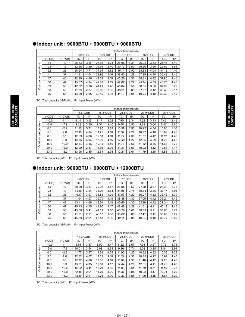
- (04 - 22) -
OU
TDO
OR
UN
ITA
OU
36R
LXFZ
OU
TDO
OR
UN
ITA
OU
36R
LXFZ
Indoor unit : 9000BTU + 9000BTU + 9000BTU �Indoor temperature
60°FDB 65°FDB 70°FDB 75°FDB 78°FDB
Out
door
tem
pera
ture
(°FDB) (°FWB) TC IP TC IP TC IP TC IP TC IP14 12 28.83 3.15 27.89 3.24 26.96 3.34 26.02 3.43 25.46 3.49 23 19 32.86 3.30 31.79 3.40 30.73 3.50 29.66 3.60 29.02 3.65 32 28 38.64 3.71 37.39 3.82 36.14 3.93 34.88 4.04 34.13 4.10 41 37 41.31 4.04 39.98 4.16 38.63 4.28 37.29 4.40 36.49 4.46 47 43 42.99 4.06 41.59 4.18 40.20 4.30 38.81 4.42 37.96 4.46 50 47 45.57 4.04 44.10 4.15 42.62 4.27 41.14 4.39 40.25 4.46 59 50 42.82 3.36 41.43 3.46 40.04 3.56 38.65 3.66 37.82 3.72 68 59 41.29 2.87 39.95 2.95 38.61 3.03 37.27 3.12 36.46 3.17 75 65 44.59 2.85 43.15 2.93 41.70 3.01 40.25 3.10 39.38 3.15
TC : Total capacity (kBTU/h) IP : Input Power (kW)
Indoor temperature15.6°CDB 18.3°CDB 21.1°CDB 23.9°CDB 25.6°CDB
Out
door
tem
pera
ture
(°CDB) (°CWB) TC IP TC IP TC IP TC IP TC IP-10.0 -11.1 8.44 3.15 8.17 3.24 7.90 3.34 7.62 3.43 7.46 3.49 -5.0 -7.2 9.62 3.30 9.31 3.40 9.00 3.50 8.69 3.60 8.50 3.65 0.0 -2.2 11.32 3.71 10.95 3.82 10.58 3.93 10.22 4.04 10.00 4.10 5.0 2.8 12.10 4.04 11.71 4.16 11.32 4.28 10.92 4.40 10.69 4.46 8.3 6.1 12.59 4.06 12.18 4.18 11.77 4.30 11.37 4.42 11.12 4.46 10.0 8.3 13.35 4.04 12.92 4.15 12.48 4.27 12.05 4.39 11.79 4.46 15.0 10.0 12.54 3.36 12.14 3.46 11.73 3.56 11.32 3.66 11.08 3.72 20.0 15.0 12.09 2.87 11.70 2.95 11.31 3.03 10.92 3.12 10.68 3.17 23.9 18.3 13.06 2.85 12.64 2.93 12.21 3.01 11.79 3.10 11.53 3.15
TC : Total capacity (kW) IP : Input Power (kW)
Indoor unit : 9000BTU + 9000BTU + 12000BTU �Indoor temperature
60°FDB 65°FDB 70°FDB 75°FDB 78°FDB
Out
door
tem
pera
ture
(°FDB) (°FWB) TC IP TC IP TC IP TC IP TC IP14 12 30.00 3.37 29.03 3.47 28.05 3.57 27.08 3.67 26.49 3.73 23 19 34.16 3.54 33.06 3.64 31.95 3.74 30.84 3.85 30.17 3.91 32 28 40.17 3.97 38.88 4.09 37.57 4.20 36.27 4.32 35.48 4.39 41 37 41.04 4.07 39.71 4.18 38.38 4.30 37.05 4.42 36.24 4.46 47 43 43.41 4.06 42.01 4.18 40.60 4.30 39.19 4.42 38.34 4.46 50 47 45.43 4.05 43.96 4.17 42.48 4.29 41.01 4.41 40.12 4.46 59 50 43.08 3.41 41.69 3.50 40.29 3.61 38.89 3.71 38.05 3.77 68 59 41.51 2.91 40.17 3.00 38.82 3.08 37.47 3.17 36.66 3.22 75 65 45.03 2.91 43.57 2.99 42.11 3.08 40.65 3.16 39.77 3.22
TC : Total capacity (kBTU/h) IP : Input Power (kW)
Indoor temperature15.6°CDB 18.3°CDB 21.1°CDB 23.9°CDB 25.6°CDB
Out
door
tem
pera
ture
(°CDB) (°CWB) TC IP TC IP TC IP TC IP TC IP-10.0 -11.1 8.79 3.37 8.50 3.47 8.22 3.57 7.93 3.67 7.76 3.73 -5.0 -7.2 10.01 3.54 9.68 3.64 9.36 3.74 9.03 3.85 8.84 3.91 0.0 -2.2 11.77 3.97 11.39 4.09 11.00 4.20 10.62 4.32 10.39 4.39 5.0 2.8 12.02 4.07 11.63 4.18 11.24 4.30 10.85 4.42 10.62 4.46 8.3 6.1 12.72 4.06 12.30 4.18 11.89 4.30 11.48 4.42 11.23 4.46 10.0 8.3 13.31 4.05 12.87 4.17 12.44 4.29 12.01 4.41 11.75 4.46 15.0 10.0 12.62 3.41 12.21 3.50 11.80 3.61 11.39 3.71 11.15 3.77 20.0 15.0 12.16 2.91 11.76 3.00 11.37 3.08 10.98 3.17 10.74 3.22 23.9 18.3 13.19 2.91 12.76 2.99 12.33 3.08 11.90 3.16 11.65 3.22
TC : Total capacity (kW) IP : Input Power (kW)

- (04 - 23) -
OU
TDO
OR
UN
ITA
OU
36R
LXFZ
OU
TDO
OR
UN
ITA
OU
36R
LXFZ
Indoor unit : 9000BTU + 9000BTU + 18000BTU �Indoor temperature
60°FDB 65°FDB 70°FDB 75°FDB 78°FDB
Out
door
tem
pera
ture
(°FDB) (°FWB) TC IP TC IP TC IP TC IP TC IP14 12 30.22 3.20 29.24 3.29 28.26 3.39 27.28 3.48 26.69 3.54 23 19 34.14 3.35 33.03 3.45 31.93 3.55 30.82 3.65 30.15 3.71 32 28 39.83 3.54 38.54 3.65 37.24 3.75 35.95 3.86 35.17 3.92 41 37 42.93 3.95 41.54 4.06 40.15 4.18 38.75 4.30 37.91 4.37 47 43 44.91 4.06 43.46 4.18 42.00 4.30 40.54 4.42 39.66 4.46 50 47 47.35 4.14 45.82 4.26 44.28 4.38 42.75 4.46 41.82 4.46 59 50 44.49 3.45 43.05 3.54 41.61 3.65 40.17 3.75 39.30 3.81 68 59 42.56 2.96 41.18 3.04 39.80 3.13 38.42 3.22 37.59 3.27 75 65 46.10 2.97 44.61 3.05 43.11 3.14 41.62 3.23 40.72 3.28
TC : Total capacity (kBTU/h) IP : Input Power (kW)
Indoor temperature15.6°CDB 18.3°CDB 21.1°CDB 23.9°CDB 25.6°CDB
Out
door
tem
pera
ture
(°CDB) (°CWB) TC IP TC IP TC IP TC IP TC IP-10.0 -11.1 8.85 3.20 8.56 3.29 8.28 3.39 7.99 3.48 7.82 3.54 -5.0 -7.2 10.00 3.35 9.68 3.45 9.35 3.55 9.03 3.65 8.83 3.71 0.0 -2.2 11.66 3.54 11.29 3.65 10.91 3.75 10.53 3.86 10.30 3.92 5.0 2.8 12.57 3.95 12.17 4.06 11.76 4.18 11.35 4.30 11.10 4.37 8.3 6.1 13.15 4.06 12.73 4.18 12.30 4.30 11.87 4.42 11.62 4.46 10.0 8.3 13.87 4.14 13.42 4.26 12.97 4.38 12.52 4.46 12.25 4.46 15.0 10.0 13.03 3.45 12.61 3.54 12.19 3.65 11.76 3.75 11.51 3.81 20.0 15.0 12.46 2.96 12.06 3.04 11.66 3.13 11.25 3.22 11.01 3.27 23.9 18.3 13.50 2.97 13.07 3.05 12.63 3.14 12.19 3.23 11.93 3.28
TC : Total capacity (kW) IP : Input Power (kW)
Indoor unit : 9000BTU + 12000BTU + 12000BTU �Indoor temperature
60°FDB 65°FDB 70°FDB 75°FDB 78°FDB
Out
door
tem
pera
ture
(°FDB) (°FWB) TC IP TC IP TC IP TC IP TC IP14 12 30.36 3.34 29.38 3.44 28.39 3.54 27.41 3.64 26.81 3.70 23 19 34.60 3.50 33.48 3.61 32.36 3.71 31.24 3.81 30.56 3.88 32 28 40.70 3.94 39.38 4.05 38.06 4.17 36.74 4.28 35.94 4.35 41 37 41.58 3.94 40.24 4.05 38.89 4.17 37.54 4.28 36.73 4.35 47 43 43.84 4.06 42.42 4.18 41.00 4.30 39.58 4.42 38.72 4.46 50 47 46.18 4.01 44.69 4.12 43.19 4.24 41.69 4.36 40.79 4.43 59 50 43.79 3.37 42.38 3.47 40.95 3.57 39.53 3.67 38.68 3.73 68 59 42.15 2.88 40.79 2.96 39.42 3.05 38.05 3.13 37.23 3.18 75 65 45.81 2.87 44.33 2.95 42.84 3.04 41.36 3.12 40.46 3.18
TC : Total capacity (kBTU/h) IP : Input Power (kW)
Indoor temperature15.6°CDB 18.3°CDB 21.1°CDB 23.9°CDB 25.6°CDB
Out
door
tem
pera
ture
(°CDB) (°CWB) TC IP TC IP TC IP TC IP TC IP-10.0 -11.1 8.89 3.34 8.60 3.44 8.32 3.54 8.03 3.64 7.85 3.70 -5.0 -7.2 10.14 3.50 9.81 3.61 9.48 3.71 9.15 3.81 8.95 3.88 0.0 -2.2 11.92 3.94 11.53 4.05 11.15 4.17 10.76 4.28 10.53 4.35 5.0 2.8 12.18 3.94 11.79 4.05 11.39 4.17 11.00 4.28 10.76 4.35 8.3 6.1 12.84 4.06 12.43 4.18 12.01 4.30 11.59 4.42 11.34 4.46 10.0 8.3 13.53 4.01 13.09 4.12 12.65 4.24 12.21 4.36 11.95 4.43 15.0 10.0 12.83 3.37 12.41 3.47 12.00 3.57 11.58 3.67 11.33 3.73 20.0 15.0 12.35 2.88 11.95 2.96 11.55 3.05 11.14 3.13 10.90 3.18 23.9 18.3 13.42 2.87 12.98 2.95 12.55 3.04 12.11 3.12 11.85 3.18
TC : Total capacity (kW) IP : Input Power (kW)

- (04 - 24) -
OU
TDO
OR
UN
ITA
OU
36R
LXFZ
OU
TDO
OR
UN
ITA
OU
36R
LXFZ
Indoor unit : 9000BTU + 12000BTU + 18000BTU �Indoor temperature
60°FDB 65°FDB 70°FDB 75°FDB 78°FDB
Out
door
tem
pera
ture
(°FDB) (°FWB) TC IP TC IP TC IP TC IP TC IP14 12 28.87 3.06 27.93 3.14 27.00 3.23 26.06 3.33 25.50 3.38 23 19 33.22 3.24 32.14 3.33 31.06 3.43 29.99 3.53 29.34 3.59 32 28 39.35 3.53 38.08 3.63 36.80 3.74 35.52 3.84 34.76 3.91 41 37 43.16 3.94 41.76 4.05 40.36 4.17 38.96 4.28 38.12 4.36 47 43 44.91 4.06 43.46 4.18 42.00 4.30 40.54 4.42 39.66 4.46 50 47 47.35 4.09 45.82 4.21 44.28 4.33 42.75 4.45 41.82 4.46 59 50 44.49 3.44 43.05 3.53 41.61 3.64 40.17 3.74 39.30 3.80 68 59 42.56 2.96 41.18 3.04 39.80 3.13 38.42 3.22 37.59 3.27 75 65 46.10 2.97 44.61 3.05 43.11 3.14 41.62 3.23 40.72 3.28
TC : Total capacity (kBTU/h) IP : Input Power (kW)
Indoor temperature15.6°CDB 18.3°CDB 21.1°CDB 23.9°CDB 25.6°CDB
Out
door
tem
pera
ture
(°CDB) (°CWB) TC IP TC IP TC IP TC IP TC IP-10.0 -11.1 8.45 3.06 8.18 3.14 7.91 3.23 7.63 3.33 7.47 3.38 -5.0 -7.2 9.73 3.24 9.41 3.33 9.10 3.43 8.78 3.53 8.59 3.59 0.0 -2.2 11.53 3.53 11.15 3.63 10.78 3.74 10.40 3.84 10.18 3.91 5.0 2.8 12.64 3.94 12.23 4.05 11.82 4.17 11.41 4.28 11.16 4.36 8.3 6.1 13.15 4.06 12.73 4.18 12.30 4.30 11.87 4.42 11.62 4.46 10.0 8.3 13.87 4.09 13.42 4.21 12.97 4.33 12.52 4.45 12.25 4.46 15.0 10.0 13.03 3.44 12.61 3.53 12.19 3.64 11.76 3.74 11.51 3.80 20.0 15.0 12.46 2.96 12.06 3.04 11.66 3.13 11.25 3.22 11.01 3.27 23.9 18.3 13.50 2.97 13.07 3.05 12.63 3.14 12.19 3.23 11.93 3.28
TC : Total capacity (kW) IP : Input Power (kW)
Indoor unit : 12000BTU + 12000BTU + 12000BTU �Indoor temperature
60°FDB 65°FDB 70°FDB 75°FDB 78°FDB
Out
door
tem
pera
ture
(°FDB) (°FWB) TC IP TC IP TC IP TC IP TC IP14 12 30.66 3.36 29.66 3.46 28.67 3.56 27.67 3.66 27.08 3.72 23 19 34.96 3.52 33.83 3.62 32.70 3.73 31.56 3.83 30.88 3.90 32 28 41.35 3.71 40.01 3.82 38.67 3.93 37.32 4.04 36.52 4.10 41 37 43.96 3.91 42.54 4.02 41.11 4.13 39.68 4.25 38.83 4.32 47 43 44.91 4.06 43.46 4.18 42.00 4.30 40.54 4.42 39.66 4.46 50 47 47.59 4.05 46.05 4.16 44.51 4.28 42.96 4.40 42.03 4.46 59 50 45.13 3.41 43.67 3.51 42.20 3.61 40.74 3.71 39.86 3.77 68 59 43.18 2.87 41.78 2.95 40.38 3.04 38.98 3.12 38.13 3.17 75 65 46.79 2.86 45.28 2.94 43.76 3.03 42.24 3.11 41.32 3.16
TC : Total capacity (kBTU/h) IP : Input Power (kW)
Indoor temperature15.6°CDB 18.3°CDB 21.1°CDB 23.9°CDB 25.6°CDB
Out
door
tem
pera
ture
(°CDB) (°CWB) TC IP TC IP TC IP TC IP TC IP-10.0 -11.1 8.98 3.36 8.69 3.46 8.40 3.56 8.11 3.66 7.93 3.72 -5.0 -7.2 10.24 3.52 9.91 3.62 9.58 3.73 9.24 3.83 9.04 3.90 0.0 -2.2 12.11 3.71 11.72 3.82 11.33 3.93 10.93 4.04 10.70 4.10 5.0 2.8 12.88 3.91 12.46 4.02 12.04 4.13 11.62 4.25 11.37 4.32 8.3 6.1 13.15 4.06 12.73 4.18 12.30 4.30 11.87 4.42 11.62 4.46 10.0 8.3 13.94 4.05 13.49 4.16 13.04 4.28 12.58 4.40 12.31 4.46 15.0 10.0 13.22 3.41 12.79 3.51 12.36 3.61 11.93 3.71 11.67 3.77 20.0 15.0 12.65 2.87 12.24 2.95 11.83 3.04 11.42 3.12 11.17 3.17 23.9 18.3 13.70 2.86 13.26 2.94 12.82 3.03 12.37 3.11 12.10 3.16
TC : Total capacity (kW) IP : Input Power (kW)

- (04 - 25) -
OU
TDO
OR
UN
ITA
OU
36R
LXFZ
OU
TDO
OR
UN
ITA
OU
36R
LXFZ
Indoor unit : 7000BTU + 7000BTU + 7000BTU + 7000BTU �Indoor temperature
60°FDB 65°FDB 70°FDB 75°FDB 78°FDB
Out
door
tem
pera
ture
(°FDB) (°FWB) TC IP TC IP TC IP TC IP TC IP14 12 29.89 2.85 28.92 2.93 27.95 3.01 26.98 3.10 26.40 3.15 23 19 33.53 2.98 32.44 3.06 31.36 3.15 30.27 3.24 29.61 3.29 32 28 38.28 3.05 37.05 3.13 35.80 3.22 34.56 3.31 33.81 3.37 41 37 40.08 3.31 38.78 3.41 37.48 3.50 36.18 3.60 35.40 3.66 47 43 43.20 3.45 41.80 3.55 40.40 3.65 39.00 3.75 38.15 3.81 50 47 45.78 3.55 44.29 3.65 42.81 3.75 41.32 3.86 40.43 3.92 59 50 45.10 3.33 43.64 3.42 42.18 3.52 40.71 3.62 39.83 3.68 68 59 39.04 2.55 37.78 2.62 36.51 2.69 35.25 2.77 34.48 2.81 75 65 45.56 2.83 44.09 2.91 42.61 2.99 41.13 3.08 40.24 3.13
TC : Total capacity (kBTU/h) IP : Input Power (kW)
Indoor temperature15.6°CDB 18.3°CDB 21.1°CDB 23.9°CDB 25.6°CDB
Out
door
tem
pera
ture
(°CDB) (°CWB) TC IP TC IP TC IP TC IP TC IP-10.0 -11.1 8.75 2.85 8.47 2.93 8.19 3.01 7.90 3.10 7.73 3.15 -5.0 -7.2 9.82 2.98 9.50 3.06 9.18 3.15 8.87 3.24 8.67 3.29 0.0 -2.2 11.21 3.05 10.85 3.13 10.49 3.22 10.12 3.31 9.90 3.37 5.0 2.8 11.74 3.31 11.36 3.41 10.98 3.50 10.60 3.60 10.37 3.66 8.3 6.1 12.65 3.45 12.24 3.55 11.83 3.65 11.42 3.75 11.18 3.81 10.0 8.3 13.41 3.55 12.97 3.65 12.54 3.75 12.10 3.86 11.84 3.92 15.0 10.0 13.21 3.33 12.78 3.42 12.35 3.52 11.92 3.62 11.67 3.68 20.0 15.0 11.44 2.55 11.07 2.62 10.69 2.69 10.32 2.77 10.10 2.81 23.9 18.3 13.35 2.83 12.91 2.91 12.48 2.99 12.05 3.08 11.79 3.13
TC : Total capacity (kW) IP : Input Power (kW)
Indoor unit : 7000BTU + 7000BTU + 7000BTU + 9000BTU �Indoor temperature
60°FDB 65°FDB 70°FDB 75°FDB 78°FDB
Out
door
tem
pera
ture
(°FDB) (°FWB) TC IP TC IP TC IP TC IP TC IP14 12 30.03 2.88 29.06 2.96 28.09 3.05 27.11 3.13 26.53 3.19 23 19 33.70 3.01 32.60 3.10 31.51 3.19 30.42 3.28 29.76 3.33 32 28 38.47 3.08 37.23 3.17 35.98 3.26 34.73 3.35 33.98 3.41 41 37 40.28 3.38 38.98 3.48 37.67 3.58 36.36 3.68 35.57 3.74 47 43 43.41 3.49 42.01 3.59 40.60 3.69 39.19 3.79 38.34 3.86 50 47 46.00 3.72 44.51 3.83 43.02 3.94 41.53 4.05 40.63 4.11 59 50 45.32 3.36 43.85 3.46 42.38 3.56 40.91 3.66 40.03 3.72 68 59 39.24 2.55 37.97 2.62 36.69 2.69 35.42 2.77 34.65 2.81 75 65 45.79 2.83 44.31 2.91 42.82 2.99 41.34 3.08 40.44 3.13
TC : Total capacity (kBTU/h) IP : Input Power (kW)
Indoor temperature15.6°CDB 18.3°CDB 21.1°CDB 23.9°CDB 25.6°CDB
Out
door
tem
pera
ture
(°CDB) (°CWB) TC IP TC IP TC IP TC IP TC IP-10.0 -11.1 8.80 2.88 8.51 2.96 8.23 3.05 7.94 3.13 7.77 3.19 -5.0 -7.2 9.87 3.01 9.55 3.10 9.23 3.19 8.91 3.28 8.72 3.33 0.0 -2.2 11.27 3.08 10.90 3.17 10.54 3.26 10.17 3.35 9.95 3.41 5.0 2.8 11.80 3.38 11.42 3.48 11.03 3.58 10.65 3.68 10.42 3.74 8.3 6.1 12.72 3.49 12.30 3.59 11.89 3.69 11.48 3.79 11.23 3.86 10.0 8.3 13.47 3.72 13.04 3.83 12.60 3.94 12.16 4.05 11.90 4.11 15.0 10.0 13.27 3.36 12.84 3.46 12.41 3.56 11.98 3.66 11.72 3.72 20.0 15.0 11.49 2.55 11.12 2.62 10.75 2.69 10.37 2.77 10.15 2.81 23.9 18.3 13.41 2.83 12.98 2.91 12.54 2.99 12.11 3.08 11.85 3.13
TC : Total capacity (kW) IP : Input Power (kW)

- (04 - 26) -
OU
TDO
OR
UN
ITA
OU
36R
LXFZ
OU
TDO
OR
UN
ITA
OU
36R
LXFZ
Indoor unit : 7000BTU + 7000BTU + 7000BTU + 12000BTU �Indoor temperature
60°FDB 65°FDB 70°FDB 75°FDB 78°FDB
Out
door
tem
pera
ture
(°FDB) (°FWB) TC IP TC IP TC IP TC IP TC IP14 12 29.88 2.88 28.92 2.97 27.95 3.05 26.98 3.14 26.39 3.19 23 19 33.57 3.01 32.49 3.10 31.40 3.19 30.31 3.28 29.65 3.33 32 28 38.85 3.21 37.60 3.30 36.34 3.39 35.07 3.49 34.31 3.55 41 37 40.68 3.38 39.36 3.48 38.04 3.58 36.72 3.68 35.92 3.74 47 43 43.84 3.52 42.42 3.62 41.00 3.72 39.58 3.82 38.72 3.89 50 47 46.46 3.63 44.95 3.73 43.44 3.84 41.94 3.94 41.03 4.01 59 50 45.55 3.41 44.07 3.51 42.60 3.61 41.12 3.71 40.23 3.77 68 59 38.74 2.55 37.49 2.62 36.23 2.69 34.97 2.77 34.22 2.81 75 65 45.21 2.83 43.75 2.91 42.28 2.99 40.82 3.08 39.93 3.13
TC : Total capacity (kBTU/h) IP : Input Power (kW)
Indoor temperature15.6°CDB 18.3°CDB 21.1°CDB 23.9°CDB 25.6°CDB
Out
door
tem
pera
ture
(°CDB) (°CWB) TC IP TC IP TC IP TC IP TC IP-10.0 -11.1 8.75 2.88 8.47 2.97 8.19 3.05 7.90 3.14 7.73 3.19 -5.0 -7.2 9.83 3.01 9.52 3.10 9.20 3.19 8.88 3.28 8.68 3.33 0.0 -2.2 11.38 3.21 11.01 3.30 10.64 3.39 10.27 3.49 10.05 3.55 5.0 2.8 11.91 3.38 11.53 3.48 11.14 3.58 10.75 3.68 10.52 3.74 8.3 6.1 12.84 3.52 12.43 3.62 12.01 3.72 11.59 3.82 11.34 3.89 10.0 8.3 13.61 3.63 13.17 3.73 12.72 3.84 12.28 3.94 12.02 4.01 15.0 10.0 13.34 3.41 12.91 3.51 12.48 3.61 12.04 3.71 11.78 3.77 20.0 15.0 11.35 2.55 10.98 2.62 10.61 2.69 10.24 2.77 10.02 2.81 23.9 18.3 13.24 2.83 12.81 2.91 12.38 2.99 11.95 3.08 11.70 3.13
TC : Total capacity (kW) IP : Input Power (kW)
Indoor unit : 7000BTU + 7000BTU + 7000BTU + 18000BTU* �*Wall mounted ASU18RLF cannot be connected in this combination.
Indoor temperature60°FDB 65°FDB 70°FDB 75°FDB 78°FDB
Out
door
tem
pera
ture
(°FDB) (°FWB) TC IP TC IP TC IP TC IP TC IP14 12 29.24 2.77 28.30 2.85 27.35 2.93 26.40 3.01 25.83 3.06 23 19 33.46 2.93 32.38 3.01 31.29 3.10 30.21 3.19 29.55 3.24 32 28 39.33 3.21 38.05 3.30 36.78 3.39 35.50 3.49 34.73 3.55 41 37 41.89 3.38 40.54 3.48 39.18 3.58 37.82 3.68 37.00 3.74 47 43 44.91 3.64 43.46 3.74 42.00 3.85 40.54 3.96 39.66 4.02 50 47 47.59 3.72 46.05 3.83 44.50 3.94 42.96 4.05 42.03 4.11 59 50 46.66 3.41 45.15 3.51 43.63 3.61 42.12 3.71 41.21 3.77 68 59 39.69 2.55 38.40 2.62 37.11 2.69 35.83 2.77 35.05 2.81 75 65 46.32 2.83 44.82 2.91 43.31 2.99 41.81 3.08 40.91 3.13
TC : Total capacity (kBTU/h) IP : Input Power (kW)
Indoor temperature15.6°CDB 18.3°CDB 21.1°CDB 23.9°CDB 25.6°CDB
Out
door
tem
pera
ture
(°CDB) (°CWB) TC IP TC IP TC IP TC IP TC IP-10.0 -11.1 8.57 2.77 8.29 2.85 8.01 2.93 7.73 3.01 7.56 3.06 -5.0 -7.2 9.80 2.93 9.48 3.01 9.17 3.10 8.85 3.19 8.66 3.24 0.0 -2.2 11.52 3.21 11.15 3.30 10.77 3.39 10.40 3.49 10.17 3.55 5.0 2.8 12.27 3.38 11.87 3.48 11.47 3.58 11.08 3.68 10.84 3.74 8.3 6.1 13.15 3.64 12.73 3.74 12.30 3.85 11.87 3.96 11.62 4.02 10.0 8.3 13.94 3.72 13.49 3.83 13.04 3.94 12.58 4.05 12.31 4.11 15.0 10.0 13.67 3.41 13.22 3.51 12.78 3.61 12.34 3.71 12.07 3.77 20.0 15.0 11.62 2.55 11.25 2.62 10.87 2.69 10.49 2.77 10.27 2.81 23.9 18.3 13.57 2.83 13.13 2.91 12.69 2.99 12.25 3.08 11.98 3.13
TC : Total capacity (kW) IP : Input Power (kW)

- (04 - 27) -
OU
TDO
OR
UN
ITA
OU
36R
LXFZ
OU
TDO
OR
UN
ITA
OU
36R
LXFZ
Indoor unit : 7000BTU + 7000BTU + 9000BTU + 9000BTU �Indoor temperature
60°FDB 65°FDB 70°FDB 75°FDB 78°FDB
Out
door
tem
pera
ture
(°FDB) (°FWB) TC IP TC IP TC IP TC IP TC IP14 12 29.74 2.79 28.78 2.87 27.81 2.96 26.85 3.04 26.27 3.09 23 19 33.41 2.92 32.33 3.00 31.24 3.09 30.16 3.18 29.51 3.23 32 28 38.66 3.11 37.41 3.20 36.16 3.29 34.90 3.39 34.15 3.44 41 37 40.48 3.28 39.17 3.38 37.85 3.47 36.54 3.57 35.75 3.63 47 43 43.63 3.50 42.22 3.60 40.80 3.70 39.38 3.80 38.53 3.87 50 47 46.23 3.56 44.73 3.67 43.23 3.77 41.73 3.88 40.83 3.94 59 50 45.33 3.30 43.86 3.39 42.39 3.49 40.92 3.59 40.03 3.65 68 59 38.55 2.55 37.31 2.62 36.05 2.69 34.80 2.77 34.05 2.81 75 65 44.99 2.83 43.54 2.91 42.08 2.99 40.62 3.08 39.74 3.13
TC : Total capacity (kBTU/h) IP : Input Power (kW)
Indoor temperature15.6°CDB 18.3°CDB 21.1°CDB 23.9°CDB 25.6°CDB
Out
door
tem
pera
ture
(°CDB) (°CWB) TC IP TC IP TC IP TC IP TC IP-10.0 -11.1 8.71 2.79 8.43 2.87 8.15 2.96 7.86 3.04 7.69 3.09 -5.0 -7.2 9.79 2.92 9.47 3.00 9.15 3.09 8.83 3.18 8.64 3.23 0.0 -2.2 11.32 3.11 10.96 3.20 10.59 3.29 10.22 3.39 10.00 3.44 5.0 2.8 11.86 3.28 11.47 3.38 11.09 3.47 10.70 3.57 10.47 3.63 8.3 6.1 12.78 3.50 12.36 3.60 11.95 3.70 11.54 3.80 11.29 3.87 10.0 8.3 13.54 3.56 13.10 3.67 12.66 3.77 12.22 3.88 11.96 3.94 15.0 10.0 13.28 3.30 12.85 3.39 12.42 3.49 11.98 3.59 11.72 3.65 20.0 15.0 11.29 2.55 10.93 2.62 10.56 2.69 10.19 2.77 9.97 2.81 23.9 18.3 13.18 2.83 12.75 2.91 12.32 2.99 11.90 3.08 11.64 3.13
TC : Total capacity (kW) IP : Input Power (kW)
Indoor unit : 7000BTU + 7000BTU + 9000BTU + 12000BTU �Indoor temperature
60°FDB 65°FDB 70°FDB 75°FDB 78°FDB
Out
door
tem
pera
ture
(°FDB) (°FWB) TC IP TC IP TC IP TC IP TC IP14 12 30.32 2.88 29.34 2.96 28.36 3.04 27.37 3.13 26.78 3.18 23 19 34.06 3.01 32.96 3.09 31.86 3.18 30.75 3.27 30.09 3.32 32 28 39.42 3.20 38.15 3.29 36.87 3.39 35.59 3.48 34.82 3.54 41 37 41.27 3.38 39.94 3.48 38.60 3.58 37.26 3.68 36.45 3.74 47 43 44.48 3.61 43.04 3.71 41.60 3.82 40.16 3.93 39.29 3.99 50 47 47.14 3.72 45.61 3.83 44.08 3.94 42.55 4.05 41.63 4.11 59 50 46.21 3.39 44.72 3.49 43.22 3.59 41.72 3.69 40.82 3.75 68 59 39.31 2.55 38.04 2.62 36.76 2.69 35.49 2.77 34.72 2.81 75 65 45.88 2.83 44.39 2.91 42.90 2.99 41.41 3.08 40.52 3.13
TC : Total capacity (kBTU/h) IP : Input Power (kW)
Indoor temperature15.6°CDB 18.3°CDB 21.1°CDB 23.9°CDB 25.6°CDB
Out
door
tem
pera
ture
(°CDB) (°CWB) TC IP TC IP TC IP TC IP TC IP-10.0 -11.1 8.88 2.88 8.59 2.96 8.31 3.04 8.02 3.13 7.84 3.18 -5.0 -7.2 9.98 3.01 9.65 3.09 9.33 3.18 9.01 3.27 8.81 3.32 0.0 -2.2 11.55 3.20 11.17 3.29 10.80 3.39 10.42 3.48 10.20 3.54 5.0 2.8 12.09 3.38 11.70 3.48 11.30 3.58 10.91 3.68 10.68 3.74 8.3 6.1 13.03 3.61 12.61 3.71 12.18 3.82 11.76 3.93 11.51 3.99 10.0 8.3 13.81 3.72 13.36 3.83 12.91 3.94 12.46 4.05 12.19 4.11 15.0 10.0 13.54 3.39 13.10 3.49 12.66 3.59 12.22 3.69 11.95 3.75 20.0 15.0 11.51 2.55 11.14 2.62 10.77 2.69 10.39 2.77 10.17 2.81 23.9 18.3 13.44 2.83 13.00 2.91 12.57 2.99 12.13 3.08 11.87 3.13
TC : Total capacity (kW) IP : Input Power (kW)

- (04 - 28) -
OU
TDO
OR
UN
ITA
OU
36R
LXFZ
OU
TDO
OR
UN
ITA
OU
36R
LXFZ
Indoor unit : 7000BTU + 7000BTU + 12000BTU + 12000BTU �Indoor temperature
60°FDB 65°FDB 70°FDB 75°FDB 78°FDB
Out
door
tem
pera
ture
(°FDB) (°FWB) TC IP TC IP TC IP TC IP TC IP14 12 29.24 2.78 28.30 2.86 27.35 2.94 26.40 3.02 25.83 3.07 23 19 33.46 2.94 32.38 3.02 31.29 3.11 30.21 3.20 29.55 3.25 32 28 39.33 3.21 38.05 3.30 36.78 3.39 35.50 3.49 34.73 3.55 41 37 41.89 3.38 40.54 3.48 39.18 3.58 37.82 3.68 37.00 3.74 47 43 44.91 3.64 43.46 3.74 42.00 3.85 40.54 3.96 39.66 4.02 50 47 47.59 3.72 46.05 3.83 44.50 3.94 42.96 4.05 42.03 4.11 59 50 46.66 3.41 45.15 3.51 43.63 3.61 42.12 3.71 41.21 3.77 68 59 39.69 2.55 38.40 2.62 37.11 2.69 35.83 2.77 35.05 2.81 75 65 46.32 2.83 44.82 2.91 43.31 2.99 41.81 3.08 40.91 3.13
TC : Total capacity (kBTU/h) IP : Input Power (kW)
Indoor temperature15.6°CDB 18.3°CDB 21.1°CDB 23.9°CDB 25.6°CDB
Out
door
tem
pera
ture
(°CDB) (°CWB) TC IP TC IP TC IP TC IP TC IP-10.0 -11.1 8.57 2.78 8.29 2.86 8.01 2.94 7.73 3.02 7.56 3.07 -5.0 -7.2 9.80 2.94 9.48 3.02 9.17 3.11 8.85 3.20 8.66 3.25 0.0 -2.2 11.52 3.21 11.15 3.30 10.77 3.39 10.40 3.49 10.17 3.55 5.0 2.8 12.27 3.38 11.87 3.48 11.47 3.58 11.08 3.68 10.84 3.74 8.3 6.1 13.15 3.64 12.73 3.74 12.30 3.85 11.87 3.96 11.62 4.02 10.0 8.3 13.94 3.72 13.49 3.83 13.04 3.94 12.58 4.05 12.31 4.11 15.0 10.0 13.67 3.41 13.22 3.51 12.78 3.61 12.34 3.71 12.07 3.77 20.0 15.0 11.62 2.55 11.25 2.62 10.87 2.69 10.49 2.77 10.27 2.81 23.9 18.3 13.57 2.83 13.13 2.91 12.69 2.99 12.25 3.08 11.98 3.13
TC : Total capacity (kW) IP : Input Power (kW)
Indoor unit : 7000BTU + 9000BTU + 9000BTU + 9000BTU �Indoor temperature
60°FDB 65°FDB 70°FDB 75°FDB 78°FDB
Out
door
tem
pera
ture
(°FDB) (°FWB) TC IP TC IP TC IP TC IP TC IP14 12 30.10 2.88 29.13 2.96 28.15 3.04 27.18 3.13 26.59 3.18 23 19 33.82 3.01 32.72 3.09 31.63 3.18 30.53 3.27 29.87 3.32 32 28 39.14 3.20 37.87 3.29 36.60 3.39 35.33 3.48 34.57 3.54 41 37 40.97 3.38 39.65 3.48 38.32 3.58 36.99 3.68 36.19 3.74 47 43 44.16 3.57 42.73 3.67 41.30 3.78 39.87 3.89 39.00 3.95 50 47 46.80 3.67 45.28 3.78 43.76 3.89 42.24 4.00 41.33 4.06 59 50 45.88 3.39 44.40 3.49 42.91 3.59 41.42 3.69 40.52 3.75 68 59 39.03 2.55 37.76 2.62 36.50 2.69 35.23 2.77 34.47 2.81 75 65 45.54 2.83 44.07 2.91 42.59 2.99 41.11 3.08 40.22 3.13
TC : Total capacity (kBTU/h) IP : Input Power (kW)
Indoor temperature15.6°CDB 18.3°CDB 21.1°CDB 23.9°CDB 25.6°CDB
Out
door
tem
pera
ture
(°CDB) (°CWB) TC IP TC IP TC IP TC IP TC IP-10.0 -11.1 8.82 2.88 8.53 2.96 8.25 3.04 7.96 3.13 7.79 3.18 -5.0 -7.2 9.91 3.01 9.58 3.09 9.26 3.18 8.94 3.27 8.75 3.32 0.0 -2.2 11.46 3.20 11.09 3.29 10.72 3.39 10.35 3.48 10.12 3.54 5.0 2.8 12.00 3.38 11.61 3.48 11.22 3.58 10.83 3.68 10.60 3.74 8.3 6.1 12.93 3.57 12.52 3.67 12.10 3.78 11.68 3.89 11.42 3.95 10.0 8.3 13.71 3.67 13.26 3.78 12.82 3.89 12.37 4.00 12.11 4.06 15.0 10.0 13.44 3.39 13.00 3.49 12.57 3.59 12.13 3.69 11.87 3.75 20.0 15.0 11.43 2.55 11.06 2.62 10.69 2.69 10.32 2.77 10.10 2.81 23.9 18.3 13.34 2.83 12.91 2.91 12.48 2.99 12.04 3.08 11.78 3.13
TC : Total capacity (kW) IP : Input Power (kW)

- (04 - 29) -
OU
TDO
OR
UN
ITA
OU
36R
LXFZ
OU
TDO
OR
UN
ITA
OU
36R
LXFZ
Indoor unit : 7000BTU + 9000BTU + 9000BTU + 12000BTU �Indoor temperature
60°FDB 65°FDB 70°FDB 75°FDB 78°FDB
Out
door
tem
pera
ture
(°FDB) (°FWB) TC IP TC IP TC IP TC IP TC IP14 12 29.24 2.79 28.30 2.87 27.35 2.95 26.40 3.03 25.83 3.08 23 19 33.46 2.95 32.38 3.03 31.29 3.12 30.21 3.21 29.55 3.26 32 28 39.33 3.21 38.05 3.30 36.78 3.39 35.50 3.49 34.73 3.55 41 37 41.89 3.38 40.54 3.48 39.18 3.58 37.82 3.68 37.00 3.74 47 43 44.91 3.64 43.46 3.74 42.00 3.85 40.54 3.96 39.66 4.02 50 47 47.59 3.72 46.05 3.83 44.50 3.94 42.96 4.05 42.03 4.11 59 50 46.66 3.41 45.15 3.51 43.63 3.61 42.12 3.71 41.21 3.77 68 59 39.69 2.55 38.40 2.62 37.11 2.69 35.83 2.77 35.05 2.81 75 65 46.32 2.83 44.82 2.91 43.31 2.99 41.81 3.08 40.91 3.13
TC : Total capacity (kBTU/h) IP : Input Power (kW)
Indoor temperature15.6°CDB 18.3°CDB 21.1°CDB 23.9°CDB 25.6°CDB
Out
door
tem
pera
ture
(°CDB) (°CWB) TC IP TC IP TC IP TC IP TC IP-10.0 -11.1 8.57 2.79 8.29 2.87 8.01 2.95 7.73 3.03 7.56 3.08 -5.0 -7.2 9.80 2.95 9.48 3.03 9.17 3.12 8.85 3.21 8.66 3.26 0.0 -2.2 11.52 3.21 11.15 3.30 10.77 3.39 10.40 3.49 10.17 3.55 5.0 2.8 12.27 3.38 11.87 3.48 11.47 3.58 11.08 3.68 10.84 3.74 8.3 6.1 13.15 3.64 12.73 3.74 12.30 3.85 11.87 3.96 11.62 4.02 10.0 8.3 13.94 3.72 13.49 3.83 13.04 3.94 12.58 4.05 12.31 4.11 15.0 10.0 13.67 3.41 13.22 3.51 12.78 3.61 12.34 3.71 12.07 3.77 20.0 15.0 11.62 2.55 11.25 2.62 10.87 2.69 10.49 2.77 10.27 2.81 23.9 18.3 13.57 2.83 13.13 2.91 12.69 2.99 12.25 3.08 11.98 3.13
TC : Total capacity (kW) IP : Input Power (kW)
Indoor unit : 9000BTU + 9000BTU + 9000BTU + 9000BTU �Indoor temperature
60°FDB 65°FDB 70°FDB 75°FDB 78°FDB
Out
door
tem
pera
ture
(°FDB) (°FWB) TC IP TC IP TC IP TC IP TC IP14 12 30.61 2.91 29.62 2.99 28.63 3.08 27.64 3.16 27.04 3.22 23 19 34.39 3.04 33.28 3.13 32.16 3.22 31.05 3.31 30.37 3.36 32 28 39.80 3.21 38.51 3.30 37.22 3.39 35.93 3.49 35.15 3.55 41 37 41.67 3.38 40.32 3.48 38.97 3.58 37.61 3.68 36.80 3.74 47 43 44.91 3.64 43.46 3.74 42.00 3.85 40.54 3.96 39.66 4.02 50 47 47.59 3.72 46.05 3.83 44.50 3.94 42.96 4.05 42.03 4.11 59 50 46.66 3.41 45.15 3.51 43.63 3.61 42.12 3.71 41.21 3.77 68 59 39.69 2.55 38.40 2.62 37.11 2.69 35.83 2.77 35.05 2.81 75 65 46.32 2.83 44.82 2.91 43.31 2.99 41.81 3.08 40.91 3.13
TC : Total capacity (kBTU/h) IP : Input Power (kW)
Indoor temperature15.6°CDB 18.3°CDB 21.1°CDB 23.9°CDB 25.6°CDB
Out
door
tem
pera
ture
(°CDB) (°CWB) TC IP TC IP TC IP TC IP TC IP-10.0 -11.1 8.97 2.91 8.68 2.99 8.39 3.08 8.09 3.16 7.92 3.22 -5.0 -7.2 10.07 3.04 9.75 3.13 9.42 3.22 9.09 3.31 8.90 3.36 0.0 -2.2 11.66 3.21 11.28 3.30 10.90 3.39 10.52 3.49 10.30 3.55 5.0 2.8 12.20 3.38 11.81 3.48 11.41 3.58 11.02 3.68 10.78 3.74 8.3 6.1 13.15 3.64 12.73 3.74 12.30 3.85 11.87 3.96 11.62 4.02 10.0 8.3 13.94 3.72 13.49 3.83 13.04 3.94 12.58 4.05 12.31 4.11 15.0 10.0 13.67 3.41 13.22 3.51 12.78 3.61 12.34 3.71 12.07 3.77 20.0 15.0 11.62 2.55 11.25 2.62 10.87 2.69 10.49 2.77 10.27 2.81 23.9 18.3 13.57 2.83 13.13 2.91 12.69 2.99 12.25 3.08 11.98 3.13
TC : Total capacity (kW) IP : Input Power (kW)

- (04 - 30) -
OU
TDO
OR
UN
ITA
OU
36R
LXFZ
OU
TDO
OR
UN
ITA
OU
36R
LXFZ
Indoor unit : 18000BTU + 18000BTU (With optional parts "K9FZ1818") �Indoor temperature
60°FDB 65°FDB 70°FDB 75°FDB 78°FDB
Out
door
tem
pera
ture
(°FDB) (°FWB) TC IP TC IP TC IP TC IP TC IP14 12 28.62 3.33 27.69 3.42 26.76 3.52 25.83 3.62 25.27 3.68 23 19 31.18 3.55 30.17 3.65 29.16 3.76 28.15 3.86 27.54 3.92 32 28 35.63 3.83 34.48 3.94 33.32 4.05 32.16 4.17 31.47 4.23 41 37 39.75 4.06 38.46 4.18 37.17 4.30 35.88 4.42 35.10 4.46 47 43 42.78 4.06 41.39 4.18 40.00 4.30 38.61 4.42 37.78 4.46 50 47 45.22 4.10 43.76 4.22 42.29 4.34 40.82 4.46 39.94 4.46 59 50 42.20 3.39 40.83 3.49 39.46 3.59 38.09 3.69 37.27 3.75 68 59 40.98 2.96 39.65 3.04 38.32 3.13 36.99 3.22 36.19 3.27 75 65 44.19 2.97 42.76 3.06 41.32 3.15 39.88 3.24 39.02 3.29
TC : Total capacity (kBTU/h) IP : Input Power (kW)
Indoor temperature15.6°CDB 18.3°CDB 21.1°CDB 23.9°CDB 25.6°CDB
Out
door
tem
pera
ture
(°CDB) (°CWB) TC IP TC IP TC IP TC IP TC IP-10.0 -11.1 8.39 3.33 8.12 3.42 7.84 3.52 7.57 3.62 7.41 3.68 -5.0 -7.2 9.14 3.55 8.84 3.65 8.55 3.76 8.25 3.86 8.07 3.92 0.0 -2.2 10.44 3.83 10.10 3.94 9.76 4.05 9.43 4.17 9.22 4.23 5.0 2.8 11.65 4.06 11.27 4.18 10.89 4.30 10.51 4.42 10.29 4.46 8.3 6.1 12.51 4.06 12.11 4.18 11.70 4.30 11.29 4.42 11.05 4.46 10.0 8.3 13.26 4.10 12.83 4.22 12.40 4.34 11.96 4.46 11.71 4.46 15.0 10.0 12.37 3.39 11.97 3.49 11.57 3.59 11.16 3.69 10.92 3.75 20.0 15.0 12.01 2.96 11.62 3.04 11.23 3.13 10.84 3.22 10.61 3.27 23.9 18.3 12.95 2.97 12.53 3.06 12.11 3.15 11.69 3.24 11.44 3.29
TC : Total capacity (kW) IP : Input Power (kW)
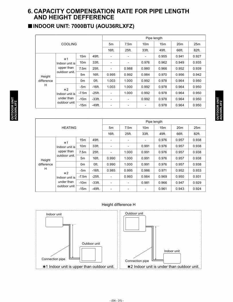
- (04 - 31) -
OU
TDO
OR
UN
ITA
OU
36R
LXFZ
OU
TDO
OR
UN
ITA
OU
36R
LXFZ
CAPACITY COMPENSATION RATE FOR PIPE LENGTH 6. AND HEIGHT DEFFERENCE
INDOOR UNIT: 7000BTU (AOU36RLXFZ) �
Height difference H
�1 Indoor unit is upper than outdoor unit. �2 Indoor unit is under than outdoor unit.
Indoor unit
Indoor unit
Connection pipe
Outdoor unit
Outdoor unit
Connection pipe
COOLING
Pipe length
5m 7.5m 10m 15m 20m 25m
16ft. 25ft. 33ft. 49ft. 66ft. 82ft.
Height difference
H
�1 Indoor unit is upper than
outdoor unit.
15m 49ft. - - - 0.955 0.941 0.927
10m 33ft. - - 0.976 0.962 0.949 0.935
7.5m 25ft. - 0.988 0.980 0.966 0.952 0.939
5m 16ft. 0.995 0.992 0.984 0.970 0.956 0.942
0m 0ft. 1.003 1.000 0.992 0.978 0.964 0.950
�2 Indoor unit is under than outdoor unit
-5m -16ft. 1.003 1.000 0.992 0.978 0.964 0.950
-7.5m -25ft. - 1.000 0.992 0.978 0.964 0.950
-10m -33ft. - - 0.992 0.978 0.964 0.950
-15m -49ft. - - - 0.978 0.964 0.950
HEATING
Pipe length
5m 7.5m 10m 15m 20m 25m
16ft. 25ft. 33ft. 49ft. 66ft. 82ft.
Height difference
H
�1 Indoor unit is upper than
outdoor unit.
15m 49ft. - - - 0.976 0.957 0.938
10m 33ft. - - 0.991 0.976 0.957 0.938
7.5m 25ft. - 1.000 0.991 0.976 0.957 0.938
5m 16ft. 0.990 1.000 0.991 0.976 0.957 0.938
0m 0ft. 0.990 1.000 0.991 0.976 0.957 0.938
�2 Indoor unit is under than outdoor unit
-5m -16ft. 0.985 0.995 0.986 0.971 0.952 0.933
-7.5m -25ft. - 0.993 0.984 0.969 0.950 0.931
-10m -33ft. - - 0.981 0.966 0.947 0.929
-15m -49ft. - - - 0.961 0.943 0.924

- (04 - 32) -
OU
TDO
OR
UN
ITA
OU
36R
LXFZ
OU
TDO
OR
UN
ITA
OU
36R
LXFZ
INDOOR UNIT: 9000BTU (AOU36RLXFZ) �
Height difference H
�1 Indoor unit is upper than outdoor unit. �2 Indoor unit is under than outdoor unit.
Indoor unit
Indoor unit
Connection pipe
Outdoor unit
Outdoor unit
Connection pipe
COOLING
Pipe length
5m 7.5m 10m 15m 20m 25m
16ft. 25ft. 33ft. 49ft. 66ft. 82ft.
Height difference
H
�1 Indoor unit is upper than
outdoor unit.
15m 49ft. - - - 0.956 0.942 0.928
10m 33ft. - - 0.977 0.963 0.950 0.936
7.5m 25ft. - 0.988 0.981 0.967 0.954 0.940
5m 16ft. 0.999 0.992 0.985 0.971 0.957 0.943
0m 0ft. 1.007 1.000 0.993 0.979 0.965 0.951
�2 Indoor unit is under than outdoor unit
-5m -16ft. 1.007 1.000 0.993 0.979 0.965 0.951
-7.5m -25ft. - 1.000 0.993 0.979 0.965 0.951
-10m -33ft. - - 0.993 0.979 0.965 0.951
-15m -49ft. - - - 0.979 0.965 0.951
HEATING
Pipe length
5m 7.5m 10m 15m 20m 25m
16ft. 25ft. 33ft. 49ft. 66ft. 82ft.
Height difference
H
�1 Indoor unit is upper than
outdoor unit.
15m 49ft. - - - 0.977 0.958 0.939
10m 33ft. - - 0.993 0.977 0.958 0.939
7.5m 25ft. - 1.000 0.993 0.977 0.958 0.939
5m 16ft. 0.993 1.000 0.993 0.977 0.958 0.939
0m 0ft. 0.993 1.000 0.993 0.977 0.958 0.939
�2 Indoor unit is under than outdoor unit
-5m -16ft. 0.988 0.995 0.988 0.972 0.954 0.934
-7.5m -25ft. - 0.993 0.986 0.970 0.952 0.932
-10m -33ft. - - 0.983 0.967 0.949 0.930
-15m -49ft. - - - 0.962 0.944 0.925
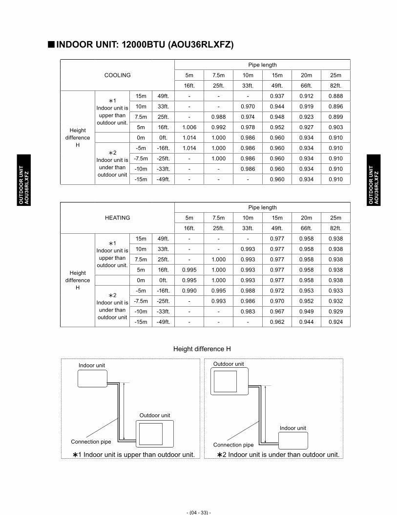
- (04 - 33) -
OU
TDO
OR
UN
ITA
OU
36R
LXFZ
OU
TDO
OR
UN
ITA
OU
36R
LXFZ
INDOOR UNIT: 12000BTU (AOU36RLXFZ) �
Height difference H
�1 Indoor unit is upper than outdoor unit. �2 Indoor unit is under than outdoor unit.
Indoor unit
Indoor unit
Connection pipe
Outdoor unit
Outdoor unit
Connection pipe
COOLING
Pipe length
5m 7.5m 10m 15m 20m 25m
16ft. 25ft. 33ft. 49ft. 66ft. 82ft.
Height difference
H
�1 Indoor unit is upper than
outdoor unit.
15m 49ft. - - - 0.937 0.912 0.888
10m 33ft. - - 0.970 0.944 0.919 0.896
7.5m 25ft. - 0.988 0.974 0.948 0.923 0.899
5m 16ft. 1.006 0.992 0.978 0.952 0.927 0.903
0m 0ft. 1.014 1.000 0.986 0.960 0.934 0.910
�2 Indoor unit is under than outdoor unit
-5m -16ft. 1.014 1.000 0.986 0.960 0.934 0.910
-7.5m -25ft. - 1.000 0.986 0.960 0.934 0.910
-10m -33ft. - - 0.986 0.960 0.934 0.910
-15m -49ft. - - - 0.960 0.934 0.910
HEATING
Pipe length
5m 7.5m 10m 15m 20m 25m
16ft. 25ft. 33ft. 49ft. 66ft. 82ft.
Height difference
H
�1 Indoor unit is upper than
outdoor unit.
15m 49ft. - - - 0.977 0.958 0.938
10m 33ft. - - 0.993 0.977 0.958 0.938
7.5m 25ft. - 1.000 0.993 0.977 0.958 0.938
5m 16ft. 0.995 1.000 0.993 0.977 0.958 0.938
0m 0ft. 0.995 1.000 0.993 0.977 0.958 0.938
�2 Indoor unit is under than outdoor unit
-5m -16ft. 0.990 0.995 0.988 0.972 0.953 0.933
-7.5m -25ft. - 0.993 0.986 0.970 0.952 0.932
-10m -33ft. - - 0.983 0.967 0.949 0.929
-15m -49ft. - - - 0.962 0.944 0.924

- (04 - 34) -
OU
TDO
OR
UN
ITA
OU
36R
LXFZ
OU
TDO
OR
UN
ITA
OU
36R
LXFZ
INDOOR UNIT: 18000BTU (AOU36RLXFZ) �
Height difference H
�1 Indoor unit is upper than outdoor unit. �2 Indoor unit is under than outdoor unit.
Indoor unit
Indoor unit
Connection pipe
Outdoor unit
Outdoor unit
Connection pipe
COOLING
Pipe length
5m 7.5m 10m 15m 20m 25m
16ft. 25ft. 33ft. 49ft. 66ft. 82ft.
Height difference
H
�1 Indoor unit is upper than
outdoor unit.
15m 49ft. - - - 0.968 0.961 0.954
10m 33ft. - - 0.982 0.976 0.969 0.962
7.5m 25ft. - 0.988 0.986 0.980 0.973 0.966
5m 16ft. 0.994 0.992 0.990 0.984 0.977 0.970
0m 0ft. 1.002 1.000 0.998 0.992 0.985 0.978
�2 Indoor unit is under than outdoor unit
-5m -16ft. 1.002 1.000 0.998 0.992 0.985 0.978
-7.5m -25ft. - 1.000 0.998 0.992 0.985 0.978
-10m -33ft. - - 0.998 0.992 0.985 0.978
-15m -49ft. - - - 0.992 0.985 0.978
HEATING
Pipe length
5m 7.5m 10m 15m 20m 25m
16ft. 25ft. 33ft. 49ft. 66ft. 82ft.
Height difference
H
�1 Indoor unit is upper than
outdoor unit.
15m 49ft. - - - 0.967 0.943 0.917
10m 33ft. - - 0.990 0.967 0.943 0.917
7.5m 25ft. - 1.000 0.990 0.967 0.943 0.917
5m 16ft. 1.010 1.000 0.990 0.967 0.943 0.917
0m 0ft. 1.010 1.000 0.990 0.967 0.943 0.917
�2 Indoor unit is under than outdoor unit
-5m -16ft. 1.005 0.995 0.985 0.962 0.938 0.912
-7.5m -25ft. - 0.993 0.983 0.960 0.936 0.910
-10m -33ft. - - 0.980 0.958 0.933 0.908
-15m -49ft. - - - 0.953 0.929 0.903

- (04 - 35) -
OU
TDO
OR
UN
ITA
OU
36R
LXFZ
OU
TDO
OR
UN
ITA
OU
36R
LXFZ
INDOOR UNIT: 24000BTU (AOU36RLXFZ) �
Height difference H
�1 Indoor unit is upper than outdoor unit. �2 Indoor unit is under than outdoor unit.
Indoor unit
Indoor unit
Connection pipe
Outdoor unit
Outdoor unit
Connection pipe
COOLING
Pipe length
5m 7.5m 10m 15m 20m 25m
16ft. 25ft. 33ft. 49ft. 66ft. 82ft.
Height difference
H
�1 Indoor unit is upper than
outdoor unit.
15m 49ft. - - - 0.978 0.969 0.953
10m 33ft. - - 0.986 0.986 0.977 0.961
7.5m 25ft. - 0.988 0.990 0.990 0.981 0.965
5m 16ft. 0.989 0.992 0.994 0.994 0.984 0.968
0m 0ft. 0.997 1.000 1.002 1.002 0.992 0.976
�2 Indoor unit is under than outdoor unit
-5m -16ft. 0.997 1.000 1.002 1.002 0.992 0.976
-7.5m -25ft. - 1.000 1.002 1.002 0.992 0.976
-10m -33ft. - - 1.002 1.002 0.992 0.976
-15m -49ft. - - - 1.002 0.992 0.976
HEATING
Pipe length
5m 7.5m 10m 15m 20m 25m
16ft. 25ft. 33ft. 49ft. 66ft. 82ft.
Height difference
H
�1 Indoor unit is upper than
outdoor unit.
15m 49ft. - - - 0.964 0.939 0.913
10m 33ft. - - 0.988 0.964 0.939 0.913
7.5m 25ft. - 1.000 0.988 0.964 0.939 0.913
5m 16ft. 1.008 1.000 0.988 0.964 0.939 0.913
0m 0ft. 1.008 1.000 0.988 0.964 0.939 0.913
�2 Indoor unit is under than outdoor unit
-5m -16ft. 1.003 0.995 0.983 0.959 0.934 0.909
-7.5m -25ft. - 0.993 0.981 0.957 0.932 0.907
-10m -33ft. - - 0.978 0.954 0.929 0.904
-15m -49ft. - - - 0.949 0.925 0.899

- (04 - 36) -
OU
TDO
OR
UN
ITA
OU
36R
LXFZ
OU
TDO
OR
UN
ITA
OU
36R
LXFZ
ADDITIONAL CHARGE CALCULATION7. MODEL � : AOU36RLXFZ
Refrigerant charge �
●3 or 4 indoor units are connected
Total pipe lengthft. 164 or less 197 230 (MAX)
0.27 oz./ft.
25 g/m
m 50 or less 60 70 (MAX)
Additional chargelbs. oz. 0 8.9 oz. 1 lb. 1.8 oz.
g 0 250 500
●2 indoor units are connected (with optional parts K9FZ1818)
Total pipe lengthft. 65 or less 98 131 (MAX)
0.27 oz./ft.
25 g/m
m 20 or less 30 40 (MAX)
Additional chargelbs. oz. 0 8.9 oz. 1 lb. 1.8 oz.
g 0 250 500
Refrigerant type R410A
Refrigerant amountlbs. oz. 7 lbs. 4 oz.
g 3300
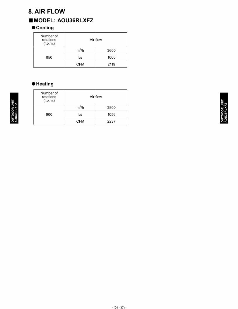
- (04 - 37) -
OU
TDO
OR
UN
ITA
OU
36R
LXFZ
OU
TDO
OR
UN
ITA
OU
36R
LXFZ
AIR FLOW8. MODEL � : AOU36RLXFZCooling �
Heating �
Number of rotations (r.p.m.)
Air flow
850
m3/h 3600
l/s 1000
CFM 2119
Number of rotations (r.p.m.)
Air flow
900
m3/h 3800
l/s 1056
CFM 2237

- (04 - 38) -
OU
TDO
OR
UN
ITA
OU
36R
LXFZ
OU
TDO
OR
UN
ITA
OU
36R
LXFZ
OPERATION NOISE9. NOISE LEVEL CURVE9-1.
MODEL � : AOU36RLXFZHeating �Cooling �
Oct
ave
band
sou
nd p
ress
ure
leve
l, dB
:(0dB
=0.0
002μ
bar)
80
70
60
50
40
30
20
10
0
NC-65
NC-60
NC-55
NC-50
NC-45
NC-40
NC-35
NC-30
NC-25
NC-20
NC-15O
ctav
e ba
nd s
ound
pre
ssur
e le
vel,
dB:(0
dB=0
.000
2μba
r)
80
70
60
50
40
30
20
10
0
NC-65
NC-60
NC-55
NC-50
NC-45
NC-40
NC-35
NC-30
NC-25
NC-20
NC-15
Octave band center frequency,Hz
63 125 250 500 1,000 2,000 4,000 8,000
Octave band center frequency,Hz
63 125 250 500 1,000 2,000 4,000 8,000
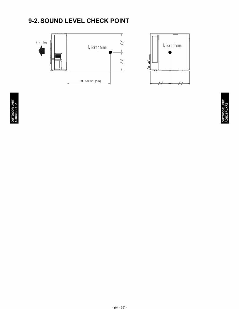
- (04 - 39) -
OU
TDO
OR
UN
ITA
OU
36R
LXFZ
OU
TDO
OR
UN
ITA
OU
36R
LXFZ
SOUND LEVEL CHECK POINT9-2.
3ft. 3-3/8in. (1m)

- (04 - 40) -
OU
TDO
OR
UN
ITA
OU
36R
LXFZ
OU
TDO
OR
UN
ITA
OU
36R
LXFZ
ELECTRIC CHARACTERISTICS10.
Model name AOU36RLXFZ
Power supply Voltage V 208 / 230 ~Frequency Hz 60
Max. operation current A 20.1 / 20.1Starting current A 15.1
*1) Wiring spec.
Main fuse (Circuit breaker) current
A 30.0
Power cable AWG 10*2) Limited wiring length ft. 53 / 59
*1) Wiring spec. : selected sample (Selected based on Japan Electrotechnical Standard and Codes Committee E0005)
*2) Limited wiring length : This is the wiring length in case voltage descent is less than 2%.When the wiring length become long, please select the wiring of a more larger diameter.

- (04 - 41) -
OU
TDO
OR
UN
ITA
OU
36R
LXFZ
OU
TDO
OR
UN
ITA
OU
36R
LXFZ
SAFETY DEVICES11.
Protection formModel
AOU36RLXFZ
Circuit protection
Current fuse (MAIN PCB)3.15A 250V
5A 250V
Current fuse (NEAR THE TERMINAL)
10A 250V
Fan motor protection Temperature Thermistor 212+27 -18°F OFF 203+27 -18°F ON
100+15 -10°C OFF 95+15 -10°C ON
Compressor protection Temperature Thermistor257±4°F OFF 176±4°F ON
125±2°C OFF 80±2°C ON
Refrigerant circuit protection Pressure switch (1)609±15PSI OFF 464±22PSI ON
4.2±0.1MPa OFF 3.2±0.15MPa ON
*Pressure switch (2) : For control device

- (04 - 42) -
OU
TDO
OR
UN
ITA
OU
36R
LXFZ
OU
TDO
OR
UN
ITA
OU
36R
LXFZ
OPTIONAL PARTS12.
Exterior Parts name Model No. Summary
x 4 x 1
Adapter kit K9FZ1818(UTP-MU36A2)
For 2rooms combination systemIt can exchange liquid pipe size 1/4 in. (6.35mm) for 3/8 in.(9.52mm), and 3/8 in.(9.52mm) for 1/2 in.(12.7mm) If you choice 2 indoor units system "18000 BTU + 18000BTU", then you need this kit.
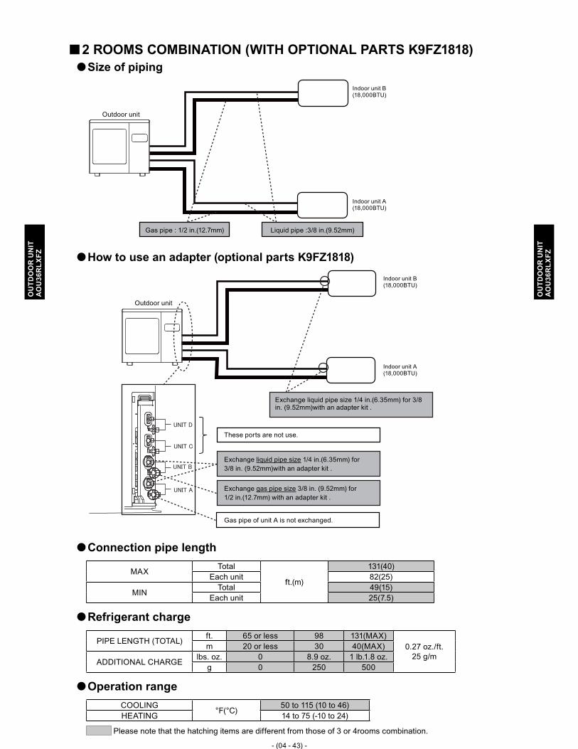
- (04 - 43) -
OU
TDO
OR
UN
ITA
OU
36R
LXFZ
OU
TDO
OR
UN
ITA
OU
36R
LXFZ
2 ROOMS COMBINATION (WITH OPTIONAL PARTS K9FZ1818) �Size of piping �
Indoor unit B(18,000BTU)
Indoor unit A(18,000BTU)
Gas pipe : 1/2 in.(12.7mm)
Outdoor unit
Liquid pipe :3/8 in.(9.52mm)
How to use an adapter (optional parts K9FZ1818) �
Indoor unit B(18,000BTU)
Indoor unit A(18,000BTU)
Exchange liquid pipe size 1/4 in.(6.35mm) for 3/8 in. (9.52mm)with an adapter kit .
These ports are not use.
Gas pipe of unit A is not exchanged.
Exchange liquid pipe size 1/4 in.(6.35mm) for 3/8 in. (9.52mm)with an adapter kit .
Exchange gas pipe size 3/8 in. (9.52mm) for 1/2 in.(12.7mm) with an adapter kit .
Outdoor unit
Connection pipe length �
MAX Total
ft.(m)
131(40)Each unit 82(25)
MIN Total 49(15)Each unit 25(7.5)
Refrigerant charge �
PIPE LENGTH (TOTAL) ft. 65 or less 98 131(MAX)0.27 oz./ft.
25 g/mm 20 or less 30 40(MAX)
ADDITIONAL CHARGE lbs. oz. 0 8.9 oz. 1 lb.1.8 oz.g 0 250 500
Operation range �
COOLING°F(°C)
50 to 115 (10 to 46)HEATING 14 to 75 (-10 to 24)
Please note that the hatching items are different from those of 3 or 4rooms combination.

- (04 - 44) -
OU
TDO
OR
UN
ITA
OU
36R
LXFZ
OU
TDO
OR
UN
ITA
OU
36R
LXFZ
INSTALLATION PRECAUTIONS13. OUTDOOR UNIT INSTALLATION PRECAUTIONS13-1.
Note: The information listed below are general precautions. Some models also include items that do not apply.
PLACES WHERE USE PROHIBITED �Places where there is the danger of combustible gas leakage •Places where sulfur gas, chlorine gas, acid, alkali, or other matter which effects equipment is •generatedPlaces not affected by heat radiation from other heat sources •Places where the air is not stagnant •Places where machinery which generates high frequencies is used •Ocean beaches and other areas where there is a lot of salt •Installation in vehicles, ships, and other conveyances •Factory, etc. where voltage fluctuations are large •
POINTS TO REMEMBER WHEN INSTALLING �The set shall be installed at a place which can withstand the weight and vibration of the outdoor (1) unitTo allow maintenance after refrigerant piping, drain piping, and electric wiring connection and (2) installation, provide an installation service space.
*Installation service space is shown on " INSTALLATION PLACE ".Be careful when installing the set at the following places.(3)
[Installation precautions]
Contents Countermeasures (Reference)When installed near adjacent houses
Perform installation work so that operating sound does not disturb the neighbors.
Install a soundproof barrier(1)
Change the installation site(2)
When there is the possibility of strong wind
If the outdoor unit is exposed to strong wind, capacity may (1) drop, frost may form during heating, and operation may be stopped by high pressure rise. In addition, when a very strong wind blows, the fan may be damaged.
When a very strong wind blows, there is the possibility (2) of the outdoor unit being toppled over if held only by foundation bolts
Install with the outlet side (1) Keep a sufficient distance away from a facing wall or fence.
Make the outlet direction and (2) wind direction perpendicular.
Fasten the outdoor unit using (3) toppling prevention hardware (procured at the site).
When snow accumulates
If the outdoor unit is covered by accumulated snow, it may not be able to operate.
Make the foundation as high as (1) possible.
Perform snow prevention work.(2) When installing the inverter type
It may generate noise in TV sets, stereos and PCs. The inverter type should be (1) installed at a sufficient distance from these equipments.