air bellows - numatics
TRANSCRIPT

Air Bellows
w w w . n u m a t i c s . c o m

Air BellowsSingle Convoluted 3-13
ASNS10-2-1 3
ASNS11-1-1 4
ASNS11-2-1 5
ASNS11-3-1 6
ASNS18-3-1 7
ASNS18-4-1 8
ASNS18-5-1 9
ASNS31-3-1 10
ASNS51-3-1 11
ASNS82-4-1 12
ASNS82-5-1 13
Double Convoluted 14-25
ASND10-4-1 14
ASND11-4-1 15
ASND18-4-1 16
ASND18-5-1 17
ASND18-6-1 18
ASND31-6-1 19
ASND31-8-1 20
ASND51-7-1 21
ASND51-8-1 22
ASND82-7-1 23
ASND82-10-1 24
ASND154-8-1 25
Triple Convoluted 26-28
ASNT51-11-1 26
ASNT82-12-1 27
ASNT154-12-1 28
Sleeve Type 29-33
ASNC2-1-1 29
ASNC6-1-1 30
ASNC6-2-1 31
ASNC6-3-1 32
ASNC8-4-1 33
Table of Contents

Information subject to change without notice. For ordering information or regarding your local sales office visit www.numatics.com.3
Air BellowsSERIES
Numatics Single Convoluted Air Bellows ASNS10-2-1
Hmax = 4.33 Hmin = 2.0Height H (in)
Volume
Vol
ume
(in3 )
Forc
e (lb
s x
1000
)
Use in blue range>4.1 only after
consultation withNumatics
120 psi
100 psi
80 psi
60 psi
40 psi
20 psi
4.0 3.5 3.0 2.5 2.0
2.0
1.8
1.6
1.4
1.2
1.0
0.8
0.6
0.4
0.2
0.0
Recommended height forVibration Isolation
40
36
32
28
24
20
16
12
8
4
0
H
3.55 DIA
max. 5.71 DIA
6.30 DIAInstallation space needed
0.79
Air inlet2 x 3/8-16 UNC 0.625 deep
Force-Height Diagram
Installation Instruction – Torque ratingMounting Holes 3/8” = 15-20 lb-ftAir Inlet 1/8” NPTF = 12-15 lb-ft
Technical Data
Min. Pressure 0 PSI
Return Force to Min. Height ≤ 27 lbs
Overall Weight with Clamped Plates 2.1 lbs
Order Data
Type Model Number
With Clamped Plates1/8 NPTF air inlet
ASNS10-2-1
Vibration Isolation – Dynamic Characteristic Values
Design Height H: Recommended 3.5 Inch, Minimum 2.7 Inch
Pressure p (psi) 40 60 80 100 120 Vol (in3)
Force (Load) (lbs) 350 530 700 800 1060 –
Spring Rate (lbs/in) 399 585 768 905 1075 30
Natural Frequency (Hz) 3.5 3.3 3.3 3.3 3.2 –
Pneumatic Application – Static Characteristic Values
Force F (lbs)
Pressure p (psi) 20 40 60 80 100 120 Vol (in3)
Height H (in) 4 120 250 370 490 620 740 34
3 220 450 670 890 1110 1340 26
2 280 560 850 1130 1410 1690 14

Information subject to change without notice. For ordering information or regarding your local sales office visit www.numatics.com.4
Air BellowsSERIES
Numatics Single Convoluted Air Bellows ASNS11-1-1
Hmax = 3.7 Hmin = 2.0Height H (in)
Volume
150
125
100
75
50
25
0 3.5
Vol
ume
(in3 )
Forc
e (lb
s x
1000
)
Use in green range>3.3 only after
consultation withNumatics
120 psi
100 psi
80 psi
60 psi
40 psi
20 psi
3.0 2.5 2.0
2.5
2.0
1.5
1.0
0.5
0.0
Recommended height forVibration Isolation
H
4.25 DIA
max. 5.91 DIA
6.50 DIAInstallation space needed
1.75
Air Inlet2 x 3/8-16 UNC0.625 deep
Force-Height Diagram
Installation Instruction – Torque ratingMounting Holes 3/8” = 15-20 lb-ftAir Inlet - 1/4” NPTF = 12-15 lb-ft
Technical Data
Min. Pressure 0 PSI
Return Force to Min. Height ≤ 56 lbs
Overall Weight with Clamped Plates 2.7 lbs
Order Data
Type Model Number
With clamped plates1/4 NPTF air inlet ASNS11-1-1
Vibration Isolation – Dynamic Characteristic Values
Design Height H: Recommended 3.0 Inch, Minimum 2.7 Inch
Pressure p (psi) 40 60 80 100 120 Vol (in3)
Force (Load) (lbs) 460 680 910 1140 1370 –
Spring Rate (lbs/in) 793 1128 1442 1710 1972 24
Natural Frequency (Hz) 3.9 3.8 3.7 3.7 3.6 –
Pneumatic Application – Static Characteristic Values
Force F (lbs)
Pressure p (psi) 20 40 60 80 100 120 Vol (in3)
Height H (in) 3 230 460 680 910 1140 1370 24
2.5 290 580 880 1170 1460 1750 20
2 350 690 1040 1390 1740 2080 12

Information subject to change without notice. For ordering information or regarding your local sales office visit www.numatics.com.5
Air BellowsSERIES
Numatics Single Convoluted Air Bellows ASNS11-2-1
Forc
e (lb
s x
1000
)
�������������������������
���������
����� �������������������
��������
�������������
��������
�
���
Force-Height Diagram
Installation Instruction – Torque ratingMounting Holes 3/8” = 15-20 lb-ftAir Inlet 1/4” NPTF = 12-15 lb-ft
Technical Data
Min. Pressure 0 PSI
Return Force to Min. Height ≤ 45 lbs
Overall Weight with Clamped Plates 2.7 lbs
Order Data
Type Model Number
With Clamped Plates1/4 NPTF Air Inlet
Additional types on request
ASNS11-2-1
Vibration Isolation – Dynamic Characteristic Values
Design Height H: Recommended 3.5 Inch, Minimum 2.7 Inch
Pressure p (psi) 40 60 80 100 120 Vol (in3)
Force (Load) (lbs) 530 790 1060 1320 1590 –
Spring Rate (lbs/in) 619 874 1146 1333 1570 54
Natural Frequency (Hz) 3.5 3.4 3.3 3.3 3.2 –
Pneumatic Application – Static Characteristic Values
Force F (lbs)
Pressure p (psi) 20 40 60 80 100 120 Vol (in3)
Height H (in) 5 190 380 570 750 940 1130 62
4 330 650 980 1310 1640 1960 46
3 410 820 1240 1650 2060 2470 28

Information subject to change without notice. For ordering information or regarding your local sales office visit www.numatics.com.6
Air BellowsSERIES
Numatics Single Convoluted Air Bellows ASNS11-3-1
Hmax = 5.9 Hmin = 2.0Height H (in)
Volume
210
180
150
120
90
60
30
0
6.0
Vol
ume
(in3 )
Forc
e (lb
s x
1000
)
Use in green range>5.1 only after
consultation withNumatics
120 psi
100 psi
80 psi
60 psi
40 psi
20 psi
4.5 4.0 2.0
3.5
3.0
2.5
2.0
1.5
1.0
0.5
0.0
Recommended height forVibration Isolation
5.5 5.0 3.5 3.0 2.5
H
4.25 DIA
max. 7.88 DIA
8.46 DIAInstallation space needed
1.75
air inlet
2 x 3/8-16 UNC0.625 deep
Force-Height Diagram
Installation Instructions - Torque ratingMounting Holes - 3/8” = 15-20 lb-ftAir Inlet 1/4” NPTF = 12-15 lb-ft
Technical Data
Min. Pressure 0 PSI
Return Force to Min. Height ≤ 45 lbs
Overall Weight with Clamped Plates 3.1 lbs
Order Data
Type Model Number
With clamped plates1/4 NPTF air inlet ASNS11-3-1
Vibration Isolation – Dynamic Characteristic Values
Design Height H: Recommended 3.0 Inch, Minimum 2.7 Inch
Pressure p (psi) 40 60 80 100 120 Vol (in3)
Force (Load) (lbs) 620 930 1240 1550 1850 –
Spring Rate (lbs/in) 449 655 844 1035 1211 90
Natural Frequency (Hz) 2.7 2.6 2.6 2.6 2.5 –
Pneumatic Application – Static Characteristic Values
Force F (lbs)
Pressure p (psi) 20 40 60 80 100 120 Vol (in3)
Height H (in) 5 230 460 690 910 1140 1370 96
4.5 300 600 910 1210 1510 1810 91
4 360 720 1080 1440 1800 2150 85
3.5 410 820 1230 1630 2040 2450 77
3 440 890 1330 1770 2210 2660 69
2.5 470 940 1410 1880 2350 2820 60

Information subject to change without notice. For ordering information or regarding your local sales office visit www.numatics.com.7
Air BellowsSERIES
Numatics Single Convoluted Air Bellows ASNS18-3-1
Forc
e (lb
s x
1000
)
Recommended heightfor Vibration Isolation
�������������������������
���������
����� �������������������
��������
�������������
��������
�
����
Force-Height Diagram
Installation Instruction – Torque ratingMounting Holes 3/8” = 15-20 lb-ftAir Inlet 3/4” NPTF = 40-50 lb-ftAir Inlet 1/4” NPTF = 12-15 lb-ft
Technical Data
Min. Pressure 0 PSI
Return Force to Min. Height ≤ 45 lbs
Overall Weight with Clamped Plates 4.5 lbs
Order Data
Type Model Number
With Clamped Plates3/4 NPTF Air Inlet ASNS18-3-1
1/4 NPTF Air Inlet ASNS18-3-1-2
Vibration Isolation – Dynamic Characteristic Values
Design Height H: Recommended 4.4 Inch, Minimum 3.5 Inch
Pressure p (psi) 40 60 80 100 120 Vol (in3)
Force (Load) (lbs) 820 1230 1640 2050 2460 –
Spring Rate (lbs/in) 690 957 1230 1426 1677 111
Natural Frequency (Hz) 2.9 2.8 2.7 2.6 2.6 –
Pneumatic Application – Static Characteristic Values
Force F (lbs)
Pressure p (psi) 20 40 60 80 100 120 Vol (in3)
Height H (in) 5 300 600 900 1200 1500 1800 120
4 470 950 1420 1900 2370 2850 105
3 600 1200 1800 2410 3010 3610 75
2 690 1370 2060 2750 3430 4120 43

Information subject to change without notice. For ordering information or regarding your local sales office visit www.numatics.com.8
Air BellowsSERIES
Numatics Single Convoluted Air Bellows ASNS18-4-1
Hmax = 5.9 Hmin = 2.0Height H (in)
Volume
250
225
200
175
150
125
100
75
50
25
0
6.0
Vol
ume
(in3 )
Forc
e (lb
s x
1000
)
Use in green range>5.1 only after
consultation withNumatics
120 psi
100 psi
80 psi
60 psi
40 psi
20 psi
4.5 4.0 2.0
2.
3.0
3.5
4.0
4.5
5.0
5
2.0
1.5
1.0
0.5
0.0
Recommended height forVibration Isolation
5.5 5.0 3.5 3.0 2.52.75
5.55 DIA
H
9.65 DIAInstallation space needed
Air Inlet 2 x 3/8-16 UNC0.625 deep
max. 9.1 DIA
Force-Height Diagram
Installation Instructions - Torque ratingMounting Holes 3/8” = 15-20 lb-ftAir Inlet 3/4" NPTF = 40-50 lb-ftAir Inlet 1/4” NPTF = 12-15 lb-ft
Additional types on request
Technical Data
Min. Pressure 0 PSI
Return Force to Min. Height ≤ 45 lbs
Overall Weight with Clamped Plates 4.2 lbs
Order Data
Type Model Number
With clamped plates3/4 NPTF air inlet ASNS18-4-1
1/4 NPTF air inlet ASNS18-4-1-2
Vibration Isolation – Dynamic Characteristic Values
Design Height H: Recommended 4.5 Inch, Minimum 3.9 Inch
Pressure p (psi) 40 60 80 100 120 Vol (in3)
Force (Load) (lbs) 970 1450 1940 2420 2910 –
Spring Rate (lbs/in) 693 1004 1316 1558 1866 123
Natural Frequency (Hz) 2.7 2.6 2.6 2.6 2.5 –
Pneumatic Application – Static Characteristic Values
Force F (lbs)
Pressure p (psi) 20 40 60 80 100 120 Vol (in3)
Height H (in) 5 390 790 1180 1580 1970 2360 133
4.5 480 970 1450 1940 2420 2910 123
4 570 1130 1700 2270 2830 3400 111
3.5 630 1260 1890 2530 3160 3790 96
3 690 1380 2060 2750 3440 4130 83
2.5 720 1450 2170 2890 3620 4340 68

Information subject to change without notice. For ordering information or regarding your local sales office visit www.numatics.com.9
Air BellowsSERIES
Additional types on request
Numatics Single Convoluted Air Spring ASNS18-5-1
120 psi
100 psi
80 psi
60 psi
40 psi
20 psi
Volume
Recommended heightfor Vibration Isolation
5.0
4.5
4.0
3.5
3.0
2.5
2.0
1.5
1.0
0.5
0.0
250
200
150
100
50
0
7.0 6.5 6.0 5.5 5.0 4.5 4.0 3.5 3.0 2.5 2.0
Use in dotted range>6.2 in only afterconsultation with Numatics
Hmax=6.7 Hmin=2.0Height H (in)
Forc
e (lb
s x
1000
)
Volu
me
(in3 )
5.55 DIA
max. 9.25 DIA
9.84 DIAInstallation space needed
H
2.75
Air inlet
2 x 3/8-16 UNC0.625 deep
Force-Height Diagram
Installation Instruction – 3/8-16 UNC = 15-20 LBxFTMounting holes - 3/8” = 15-20 lb-ft3/4 NPTF = 40-50 LBxFTAir Inlet 3/4” NPTF = 40-50 lb-ftAir Inlet 1/4” NPTF = 12-15 lb-ft
Technical Data
Min. Pressure 0 PSI
Return Force to Min. Height ≤ 45 lbs
Overall Weight with Clamped Plates 4.2 lbs
Order Data
Type Model Number
With Clamped Plates3/4 NPTF Air Inlet ASNS18-5-1
1/4 NPTF Air Inlet ASNS18-5-1-2
Vibration Isolation – Dynamic Characteristic Values
Design Height H: Recommended 5.5 Inch, Minimum 4.92 Inch
Pressure p (psi) 40 60 80 100 120 Vol (in3)
Force (Load) (lbs) 950 1420 1890 2370 2840 –
Spring Rate (lbs/in) 609 856 1090 1294 1524 173
Natural Frequency (Hz) 2.9 2.8 2.7 2.6 2.6 –
Pneumatic Application – Static Characteristic Values
Force F (lbs)
Pressure p (psi) 20 40 60 80 100 120 Vol (in3)
Height H (in) 6 400 790 1190 1580 1980 2370 181
5.5 470 950 1420 1890 2370 2840 173
5 540 1080 1610 2150 2690 3230 162
4.5 500 1180 1770 2360 3960 4550 150
4 640 1280 1910 2550 3190 3830 136
3.5 670 1340 2020 2690 3360 4030 122
3 700 1390 2090 2790 3490 4180 107

Information subject to change without notice. For ordering information or regarding your local sales office visit www.numatics.com.10
Air BellowsSERIES
Numatics Single Convoluted Air Bellows ASNS31-3-1
Forc
e (lb
s x
1000
)
Recommended heightfor Vibration Isolation 120
psi
�������������������������
��������� ����� �������������������
��������
�������������
��������
�
����
���
Force-Height Diagram
Installation Instruction – Torque ratingMounting Holes 3/8” = 15-20 lb-ftAir Inlet 1/4" NPTF = 12-15lb-ftAir Inlet 3/4” NPTF = 40-50 lb-ft
Technical Data
Min. Pressure 0 PSI
Return Force to Min. Height ≤ 45 lbs
Overall Weight with Clamped Plates 5.1 lbs
Order Data
Type Model Number
With clamped plates3/4 NPTF air inlet ASNS18-3-1
1/4 NPTF air inlet ASNS18-3-1-2
Vibration Isolation – Dynamic Characteristic Values
Design Height H: Recommended 4.4 Inch, Minimum 3.5 Inch
Pressure p (psi) 40 60 80 100 120 Vol (in3)
Force (Load) (lbs) 1200 1810 2410 3010 3610 –
Spring Rate (lbs/in) 787 1211 1638 2081 2510 166
Natural Frequency (Hz) 2.5 2.6 2.6 2.6 2.6 –
Pneumatic Application – Static Characteristic Values
Force F (lbs)
Pressure p (psi) 20 40 60 80 100 120 Vol (in3)
Height H (in) 5 470 950 1420 1890 2370 2840 179
4 670 1350 2020 2690 3360 4040 144
3 820 1640 2460 3280 4100 4930 105
2 920 1830 2750 3670 4580 5500 62

Information subject to change without notice. For ordering information or regarding your local sales office visit www.numatics.com.11
Air BellowsSERIES
Numatics Single Convoluted Air Bellows ASNS51-3-1
Hmax = 6.0 Hmin = 2.2Height H (in)
12
10
8
6
4
2
06.0 5.5 5.0 4.5 4.0 3.5 3.0 2.5 2.0
ni( emulo
V3 )
)0001 x sbl( ecroF
120 psi
100 psi
80 psi
60 psi
40 psi
20 psi
600
500
400
300
200
100
0
Use in green range>5.5 only after
consultation withNumatics
emuloV
Recommended height forVibration Isolation
Installation space needed
Air inlet 2 x 3/8" - 16 UNC0.625 deep
13.39 DIA
max. 12.80 DIA
8.98 DIA
H
6.20
2.88
Force-Height Diagram
Installation instruction - Torque RatingMounting Holes 3/8” = 15-20 LB-FTAir Inlet 3/4” NPTF = 40-50 LB-FTAir Inlet 1/4” NPTF = 12-15 LB-FT
Technical Data
Min. Pressure 0 PSI
Return Force to Min. Height ≤ 67 lbs
Overall Weight with Clamped Plates 9.1 lbs
Order Data
Type Model Number
With clamped plates3/4 NPTF air inlet
2.8 inch excentrical ASNS51-3-1
1/4 NPTF air inlet ASNS51-3-1-2Vibration Isolation – Dynamic Characteristic Values
Design Height H: Recommended 5.5 Inch, Minimum 4.92 Inch
Pressure p (psi) 40 60 80 100 120 Vol (in3)
Force (Load) (lbs) 2450 3680 4900 6130 7350 –
Spring Rate (lbs/in) 1388 1943 2479 2939 3466 415
Natural Frequency (Hz) 2.4 2.3 2.2 2.2 2.2 –
Pneumatic Application – Static Characteristic Values
Force F (lbs)
Pressure p (psi) 20 40 60 80 100 120 Vol (in3)
Height H (in) 5 1150 2300 3450 4600 5760 6910 412
4 1400 2800 4210 5610 7010 8410 341
3 1590 3180 4760 6350 7940 9530 285

Information subject to change without notice. For ordering information or regarding your local sales office visit www.numatics.com.12
Air BellowsSERIES
Numatics Single Convoluted Air Bellows ASNS82-4-1
Forc
e (lb
s x
1000
)
Recommended heightfor Vibration Isolation
Installation space needed
Air inlet 4 x 3/8" - 16 UNC0.625 deep
16.55 DIA
max. 15.95 DIA
11.30 DIA
H
6.25
6.25
Force-Height Diagram
Installation Instruction – Torque ratingMounting Holes 3/8” = 15-20 lb-ftAir Inlet 1/4" NPTF = 12-15lb-ftAir Inlet 3/4” NPTF = 40-50 lb-ft
Technical Data
Min. Pressure 0 PSI
Return Force to Min. Height ≤ 67 lbs
Overall Weight with Clamped Plates 12.9 lbs
Order Data
Type Model Number
With clamped plates3/4 NPTF air inlet3.12 inch excentrical
ASNS82-4-1
1/4 NPTF air inlet ASNS82-4-1-2
Vibration Isolation – Dynamic Characteristic Values
Design Height H: Recommended 5.7 Inch, Minimum 4.3 Inch
Pressure p (psi) 40 60 80 100 120 Vol (in3)
Force (Load) (lbs) 3260 4900 6530 8160 9790 –
Spring Rate (lbs/in) 2084 2953 3830 4572 5403 607
Natural Frequency (Hz) 2.5 2.4 2.4 2.4 2.3 –
Pneumatic Application – Static Characteristic Values
Force F (lbs)
Pressure p (psi) 20 40 60 80 100 120 Vol (in3)
Height H (in) 6 1480 2970 4450 5940 7420 8910 621
5 1930 3860 5790 7720 9660 11,590 564
4 2260 4510 6770 9020 11,280 13,540 482
3 2480 4970 7450 9930 12,410 14,900 357
Information subject to change without notice. For ordering information or regarding your local sales office visit www.numatics.com.13
Air BellowsSERIES
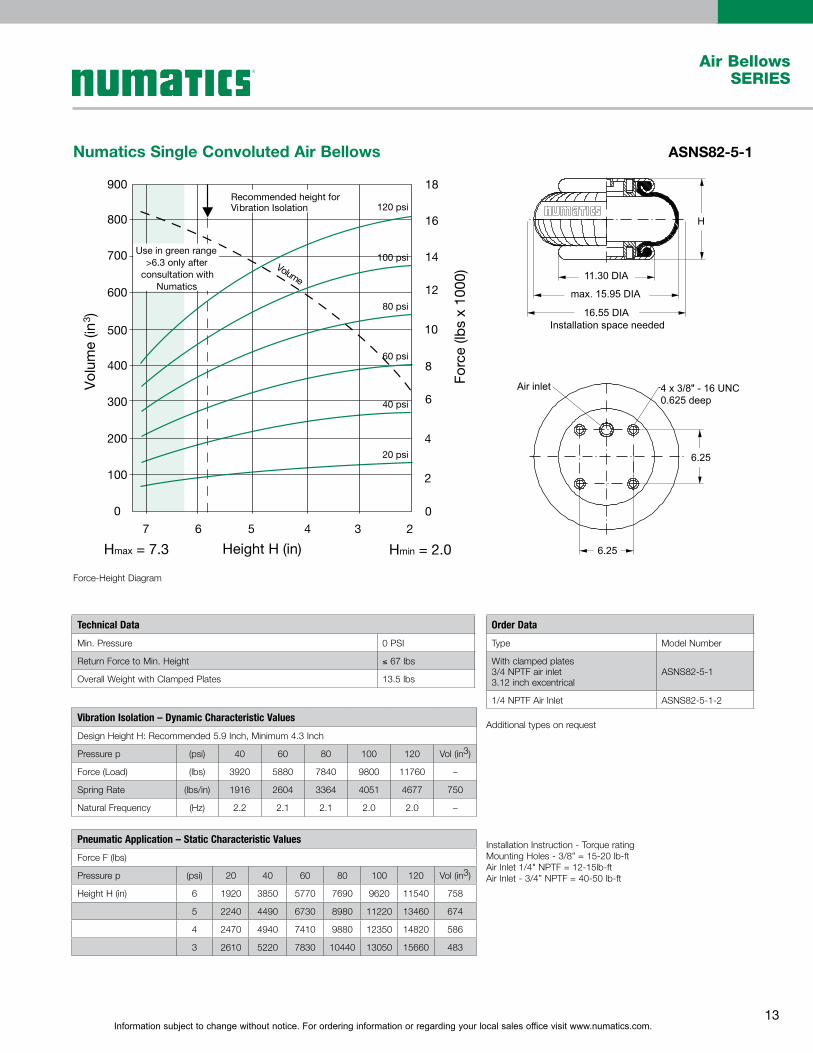
Numatics Single Convoluted Air Bellows ASNS82-5-1
Hmax = 7.3 Hmin = 2.0Height H (in)
Volume
900
800
700
600
500
400
300
200
100
0
Vol
ume
(in3 )
Forc
e (lb
s x
1000
)
Use in green range>6.3 only after
consultation withNumatics
120 psi
100 psi
80 psi
60 psi
40 psi
20 psi
2
4
6
8
10
12
14
16
18
0
Recommended height forVibration Isolation
7 6 5 4 3 2
Installation space needed
Air inlet 4 x 3/8" - 16 UNC0.625 deep
16.55 DIA
max. 15.95 DIA
11.30 DIA
H
6.25
6.25
Force-Height Diagram
Installation Instruction - Torque ratingMounting Holes - 3/8” = 15-20 lb-ftAir Inlet 1/4" NPTF = 12-15lb-ftAir Inlet - 3/4” NPTF = 40-50 lb-ft
Additional types on request
Technical Data
Min. Pressure 0 PSI
Return Force to Min. Height ≤ 67 lbs
Overall Weight with Clamped Plates 13.5 lbs
Order Data
Type Model Number
With clamped plates3/4 NPTF air inlet3.12 inch excentrical
ASNS82-5-1
1/4 NPTF Air Inlet ASNS82-5-1-2
Vibration Isolation – Dynamic Characteristic Values
Design Height H: Recommended 5.9 Inch, Minimum 4.3 Inch
Pressure p (psi) 40 60 80 100 120 Vol (in3)
Force (Load) (lbs) 3920 5880 7840 9800 11760 –
Spring Rate (lbs/in) 1916 2604 3364 4051 4677 750
Natural Frequency (Hz) 2.2 2.1 2.1 2.0 2.0 –
Pneumatic Application – Static Characteristic Values
Force F (lbs)
Pressure p (psi) 20 40 60 80 100 120 Vol (in3)
Height H (in) 6 1920 3850 5770 7690 9620 11540 758
5 2240 4490 6730 8980 11220 13460 674
4 2470 4940 7410 9880 12350 14820 586
3 2610 5220 7830 10440 13050 15660 483
Information subject to change without notice. For ordering information or regarding your local sales office visit www.numatics.com.14
Air BellowsSERIES
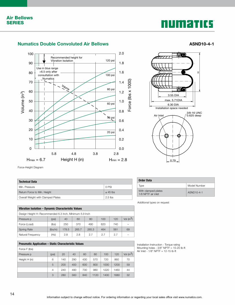
Numatics Double Convoluted Air Bellows ASND10-4-1
Hmax = 6.7 Hmin = 2.8Height H (in)
Volume
100
0
10
20
30
40
50
60
70
80
90
Vol
ume
(in3 )
Forc
e (lb
s x
1000
)
Use in blue range>6.5 only after
consultation withNumatics
120 psi
100 psi
80 psi
60 psi
40 psi
20 psi
0.2
0.4
0.6
0.8
1.0
1.2
1.4
1.6
1.8
2.0
0.0
Recommended height forVibration Isolation
5.8 4.8 3.8 2.8
H
3.55 DIA
max. 5.71DIA
6.30 DIAInstallation space needed
0.79
3/8-16 UNC 0.625 deepAir Inlet
Force-Height Diagram
Installation Instruction - Torque ratingMounting holes - 3/8” NPTF = 15-20 lb-ftAir Inlet - 1/8” NPTF = 12-15 lb-ft
Additional types on request
Technical Data
Min. Pressure 0 PSI
Return Force to Min. Height ≤ 45 lbs
Overall Weight with Clamped Plates 2.5 lbs
Order Data
Type Model Number
With clamped plates1/8 NPTF air inlet
ASND10-4-1
Vibration Isolation – Dynamic Characteristic Values
Design Height H: Recommended 6.3 Inch, Minimum 5.9 Inch
Pressure p (psi) 40 60 80 100 120 Vol (in3)
Force (Load) (lbs) 250 370 490 620 740 –
Spring Rate (lbs/in) 178.5 265.7 265.3 464 561 69
Natural Frequency (Hz) 2.8 2.8 2.7 2.7 2.7 –
Pneumatic Application – Static Characteristic Values
Force F (lbs)
Pressure p (psi) 20 40 60 80 100 120 Vol (in3)
Height H (in) 6 140 290 430 570 720 860 70
5 200 400 600 800 1000 1200 59
4 240 490 730 980 1220 1460 44
3 280 560 840 1120 1400 1680 32

Information subject to change without notice. For ordering information or regarding your local sales office visit www.numatics.com.15
Air BellowsSERIES
Numatics Double Convoluted Air Bellows ASND11-4-1
Forc
e (lb
s x
1000
)
Force-Height Diagram
Installation Instruction – Torque ratingMounting Holes 3/8” = 15-20 lb-ftAir Inlet 1/4” NPTF = 12-15 lb-ft
Additional types on request
Technical Data
Min. Pressure 0 PSI
Return Force to Min. Height ≤ 45 lbs
Overall Weight with Clamped Plates 3.3 lbs
Order Data
Type Model Number
With clamped plates1/4 Air inlet ASND11-4-1
Vibration Isolation – Dynamic Characteristic Values
Design Height H: Recommended 6.9 Inch, Minimum 6.3 Inch
Pressure p (psi) 40 60 80 100 120 Vol (in3)
Force (Load) (lbs) 460 690 920 1150 1380 –
Spring Rate (lbs/in) 273 396 517 630 750 107
Natural Frequency (Hz) 2.4 2.4 2.4 2.3 2.3 –
Pneumatic Application – Static Characteristic Values
Force F (lbs)
Pressure p (psi) 20 40 60 80 100 120 Vol (in3)
Height H (in) 7 220 450 670 900 1120 1350 108
6 280 560 850 1130 1410 1690 93
5 330 670 1000 1340 1670 2010 84
4 380 770 1150 1540 1920 2310 68
3 420 850 1270 1690 2120 2540 38

Information subject to change without notice. For ordering information or regarding your local sales office visit www.numatics.com.16
Air BellowsSERIES
Numatics Double Convoluted Air Bellows ASND18-4-1
Hmax = 9.0 Hmin = 2.8Height H (in)
Volume
450
400
350
300
250
200
150
100
0
50
Vol
ume
(in3 )
Forc
e (lb
s x
1000
)
Use in green range>7.7 only after
consultation withNumatics
120 psi
100 psi
80 psi
60 psi
40 psi
20 psi 0.5
1.0
1.5
2.0
2.5
3.0
3.5
4.0
4.5
0.0
Recommended height forVibration Isolation
8.5 7.5 6.5 5.5 4.5 3.5 2.5
H
5.55 DIA
max. 8.00 DIA
8.47 DIAInstallation space needed
2.75
Air inlet 2 x 3/8-16 UNC 0.625 deep
Force-Height Diagram
Installation Instruction - Torque ratingMounting holes - 3/8” NPTF = 15-20 lb-ftAir Inlet - 3/4” NPTF = 40-50 lb-ftAir Inlet - 1/4" NPTF = 12-15 lb-ft
Additional types on request
Technical Data
Min. Pressure 0 PSI
Return Force to Min. Height ≤ 45 lbs
Overall Weight with Clamped Plates 4.8 lbs
Order Data
Type Model Number
With clamped plates3/4 NPTF air inlet1/4 NPTF air inlet
ASND18-4-1ASND18-4-1-2
Vibration Isolation – Dynamic Characteristic Values
Design Height H: Recommended 6.9 Inch, Minimum 6.1 Inch
Pressure p (psi) 40 60 80 100 120 Vol (in3)
Force (Load) (lbs) 700 1040 1390 1740 2090 –
Spring Rate (lbs/in) 354 526 699 827 989 173
Natural Frequency (Hz) 2.3 2.2 2.2 2.2 2.1 –
Pneumatic Application – Static Characteristic Values
Force F (lbs)
Pressure p (psi) 20 40 60 80 100 120 Vol (in3)
Height H (in) 7 340 670 1010 1340 1680 2010 176
6 430 850 1280 1710 2130 2560 158
5 500 1000 1510 2010 2510 3010 133
4 570 1150 1720 2300 2870 2440 107
3 630 1270 1900 1900 2530 3160 70
Information subject to change without notice. For ordering information or regarding your local sales office visit www.numatics.com.17
Air BellowsSERIES
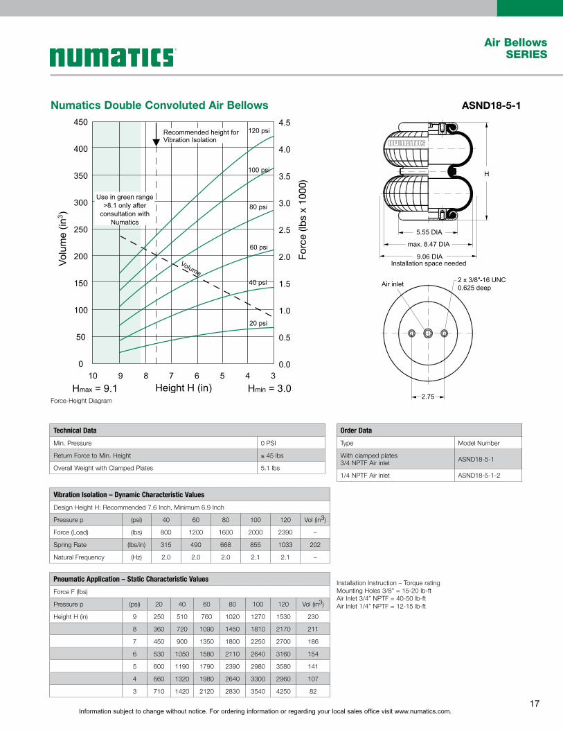
Numatics Double Convoluted Air Bellows ASND18-5-1
Forc
e (lb
s x
1000
)
�������������������������
�������������� �����������������
��������
�������������
��������
�
����Force-Height Diagram
Installation Instruction – Torque ratingMounting Holes 3/8” = 15-20 lb-ftAir Inlet 3/4” NPTF = 40-50 lb-ftAir Inlet 1/4” NPTF = 12-15 lb-ft
Technical Data
Min. Pressure 0 PSI
Return Force to Min. Height ≤ 45 lbs
Overall Weight with Clamped Plates 5.1 lbs
Order Data
Type Model Number
With clamped plates3/4 NPTF Air inlet ASND18-5-1
1/4 NPTF Air inlet ASND18-5-1-2
Vibration Isolation – Dynamic Characteristic Values
Design Height H: Recommended 7.6 Inch, Minimum 6.9 Inch
Pressure p (psi) 40 60 80 100 120 Vol (in3)
Force (Load) (lbs) 800 1200 1600 2000 2390 –
Spring Rate (lbs/in) 315 490 668 855 1033 202
Natural Frequency (Hz) 2.0 2.0 2.0 2.1 2.1 –
Pneumatic Application – Static Characteristic Values
Force F (lbs)
Pressure p (psi) 20 40 60 80 100 120 Vol (in3)
Height H (in) 9 250 510 760 1020 1270 1530 230
8 360 720 1090 1450 1810 2170 211
7 450 900 1350 1800 2250 2700 186
6 530 1050 1580 2110 2640 3160 154
5 600 1190 1790 2390 2980 3580 141
4 660 1320 1980 2640 3300 2960 107
3 710 1420 2120 2830 3540 4250 82
Information subject to change without notice. For ordering information or regarding your local sales office visit www.numatics.com.18
Air BellowsSERIES
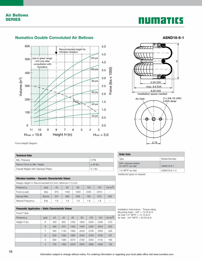
Numatics Double Convoluted Air Bellows ASND18-6-1
Hmax = 10.6 Hmin = 3.0Height H (in)
Volume
400
500
600
300
200
100
0
Vol
ume
(in3 )
Forc
e (lb
s x
1000
)
Use in green range>9.0 only after
consultation withNumatics
120 psi
100 psi
80 psi
60 psi
40 psi
20 psi0.5
1.0
1.5
2.0
2.5
3.0
3.5
4.0
5.0
4.5
0.0
Recommended height forVibration Isolation
34567891011
2 x 3/8-16 UNCAir Inlet
2.75
H
5.55 DIA
max. 8.6 DIA
9.25 DIAInstallation space needed
0.625 deep
Force-Height Diagram
Installation Instructions - Torque ratingMounting holes - 3/8” = 15-20 lb-ftAir Inlet 1/4” NPTF = 12-15 lb-ftAir Inlet - 3/4” NPTF = 40-50 lb-ft
Additional types on request
Technical Data
Min. Pressure 0 PSI
Return Force to Min. Height ≤ 45 lbs
Overall Weight with Clamped Plates 5.1 lbs
Order Data
Type Model Number
With clamped plates3/4 NPTF air inlet ASND18-6-1
1/4 NPTF air inlet ASND18-6-1-2
Vibration Isolation – Dynamic Characteristic Values
Design Height H: Recommended 8.0 Inch, Minimum 7.5 Inch
Pressure p (psi) 40 60 80 100 120 Vol (in3)
Force (Load) (lbs) 970 1450 1940 2420 2910 –
Spring Rate (lbs/in) 341 496 649 782 910 250
Natural Frequency (Hz) 1.8 1.8 1.8 1.8 1.8 –
Pneumatic Application – Static Characteristic Values
Force F (lbs)
Pressure p (psi) 20 40 60 80 100 120 Vol (in3)
Height H (in) 9 400 800 1200 1600 2000 2400 270
8 480 970 1450 1940 2420 2910 250
7 560 1120 1680 2230 2790 3350 228
6 630 1260 1890 2530 3160 3790 197
5 690 1380 2070 2760 3450 4140 166
4 730 1460 2200 2930 3660 4390 135
Information subject to change without notice. For ordering information or regarding your local sales office visit www.numatics.com.19
Air BellowsSERIES
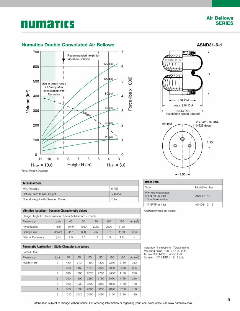
Installation Instructions - Torque ratingMounting holes - 3/8” = 15-20 lb-ftAir Inlet 3/4” NPTF = 40-50 lb-ftAir Inlet - 1/4” NPTF = 12-15 lb-ft
Numatics Double Convoluted Air Bellows ASND31-6-1
Forc
e (lb
s x
1000
)
1.50
Force-Height Diagram
Additional types on request
Technical Data
Min. Pressure 0 PSI
Return Force to Min. Height ≤ 45 lbs
Overall Weight with Clamped Plates 7 lbs
Order Data
Type Model Number
With clamped plates3/4 NPTF air inlet1.5 inch excentrical
ASND31-6-1
1/4 NPTF air inlet ASND31-6-1-2
Vibration Isolation – Dynamic Characteristic Values
Design Height H: Recommended 8.5 Inch, Minimum 7.7 Inch
Pressure p (psi) 40 60 80 100 120 Vol (in3)
Force (Load) (lbs) 1040 1560 2080 2600 3120 –
Spring Rate (lbs/in) 417 608 797 976 1163 333
Natural Frequency (Hz) 2.0 2.0 1.9 1.9 1.9 –
Pneumatic Application – Static Characteristic Values
Force F (lbs)
Pressure p (psi) 20 40 60 80 100 120 Vol (in3)
Height H (in) 9 450 910 1360 1820 2270 2730 352
8 580 1160 1740 2320 2900 3480 325
7 690 1380 2070 2770 3460 4150 290
6 790 1590 2380 3180 3970 4760 256
5 960 1930 2890 3850 4820 5780 168
4 960 1930 2890 3850 4820 5780 168
3 1020 2040 3060 4080 5100 6120 119

Information subject to change without notice. For ordering information or regarding your local sales office visit www.numatics.com.20
Air BellowsSERIES
Numatics Double Convoluted Air Bellows ASND31-8-1
Hmax = 12.8 Hmin = 3.1Height H (in)
Volume
800
1000
1200
1400
600
400
200
0
Vol
ume
(in3 )
Forc
e (lb
s x
1000
)
Use in green range>11.8 only after
consultation withNumatics
120 psi
100 psi
80 psi
60 psi
40 psi
20 psi1
2
3
4
5
6
7
0
Recommended height forVibration Isolation
13 11 9 7 5 3
H1
.50
6.34 DIA
max. 10.25 DIA
10.85 DIA Installation space needed
2 x 3/8-16 UNC? Air Inlet
3.50
0.625 deep
Force-Height Diagram
Installation Instructions - Torque ratingMounting holes - 3/8” = 15-20lb-ftAir Inlet 3/4” NPTF = 40-50 lb-ftAir Inlet 1/4" NPTF = 12-15 lb-ft
Additional types on request
Technical Data
Min. Pressure 0 PSI
Return Force to Min. Height ≤ 67 lbs
Overall Weight with Clamped Plates 7.7 lbs
Order Data
Type Model Number
With clamped plates3/4 NPTF air inlet ASND31-8-1
1/4 NPTF air inlet ASND31-8-1-2
Vibration Isolation – Dynamic Characteristic Values
Design Height H: Recommended 10.0 Inch, Minimum 9.06 Inch
Pressure p (psi) 40 60 80 100 120 Vol (in3)
Force (Load) (lbs) 1220 1830 2440 3050 3660 –
Spring Rate (lbs/in) 383 549 756 934 1087 538
Natural Frequency (Hz) 1.8 1.8 1.7 1.7 1.7 –
Pneumatic Application – Static Characteristic Values
Force F (lbs)
Pressure p (psi) 20 40 60 80 100 120 Vol (in3)
Height H (in) 11 510 1020 1530 2030 2540 3050 563
10 610 1220 1830 2440 3050 3660 538
9 700 1400 2100 2800 3500 4200 510
8 770 1530 2300 3070 3830 4600 474
7 840 1670 2510 3340 4180 5010 437
6 890 1780 2670 3560 4440 5330 396
5 930 1870 2800 3740 4670 5610 346

Information subject to change without notice. For ordering information or regarding your local sales office visit www.numatics.com.21
Air BellowsSERIES
Numatics Double Convoluted Air Bellows ASND51-7-1
Hmax = 12.0 Hmin = 3.0Height H (in)
12
10
8
6
4
2
012 11 10 9 8 7 6 5 4
3
Volu
me
(in3 )
Forc
e (lb
s x
1000
)
120 psi
100 psi
80 psi
60 psi
40 psi
20 psi
1200
1000
800
600
400
200
0
Use in green range>10.4 only afterconsultation with
Numatics
Volume
Recommended heightfor Vibration Isolation
�������������������������
��������� ����� �������������������
��������
�������������
��������
�
����
����
Force-Height Diagram
Installation Instruction – Torque ratingMounting Holes 3/8” = 15-20 lb-ftAir Inlet 3/4” NPTF = 40-50 lb-ftAir Inlet 1/4” NPTF = 12-15 lb-ft
Additional types on request
Technical Data
Min. Pressure 0 PSI
Return Force to Min. Height ≤ 67 lbs
Overall Weight with Clamped Plates 10.6 lbs
Order Data
Type Model Number
With clamped plates3/4 NPTF air inlet2.88 inch excentrical
ASND51-7-1
1/4 NPTF air inlet ASND51-7-1-2
Vibration Isolation – Dynamic Characteristic Values
Design Height H: Recommended 9.5 Inch, Minimum 8.7 Inch
Pressure p (psi) 40 60 80 100 120 Vol (in3)
Force (Load) (lbs) 2100 3150 4200 5250 6300 –
Spring Rate (lbs/in) 835 1122 1392 1592 1854 766
Natural Frequency (Hz) 2.0 1.9 1.8 1.7 1.7 –
Pneumatic Application – Static Characteristic Values
Force F (lbs)
Pressure p (psi) 20 40 60 80 100 120 Vol (in3)
Height H (in) 10 1010 2020 3030 4030 5040 6050 793
8 1280 2560 3840 5120 6400 7680 669
6 1550 3100 4650 6200 7750 9300 518
5 1650 3310 4960 6610 8270 9920 433
4 1750 3500 5250 6990 8740 10,490 340
3 1820 3630 5450 7270 9080 10,900 247

Information subject to change without notice. For ordering information or regarding your local sales office visit www.numatics.com.22
Air BellowsSERIES
Numatics Double Convoluted Air Bellows ASND51-8-1
Hmax = 14.2 Hmin = 3.1Height H (in)
Volume
800
1000
1200
600
400
200
0
Vol
ume
(in3 )
Forc
e (lb
s x
1000
)
Use in green range>11.8 only after
consultation withNumatics
120 psi
100 psi
80 psi
60 psi
40 psi
20 psi 2
4
6
8
10
12
0
15 13 11 9 7 5 3
2 x 3/8 UNCAir Inlet
6.20
2.8
8H
8.98 DIA
max. 13.4 DIA
14.0 DIA Installation space needed
0.625 deep
Force-Height Diagram
Installation Instruction - Torque ratingMounting holes - 3/8” = 15-20 lb-ftAir Inlet 3/4” NPTF = 40-50 lb-ftAir Inlet 1/4" NPTF = 12-15 lb-ft
Additional types on request
Technical Data
Min. Pressure 0 PSI
Return Force to Min. Height ≤ 67 lbs
Overall Weight with Clamped Plates 11.7 lbs
Order Data
Type Model Number
With clamped plates3/4 NPTF air inlet ASND51-8-1
1/4 NPTF air inlet ASND51-8-1-2
2.88 Inch excentricalPneumatic Application – Static Characteristic Values
Force F (lbs)
Pressure p (psi) 20 40 60 80 100 120 Vol (in3)
Height H (in) 11 1190 2380 3580 4770 5960 7150 823
9 1480 2960 4440 5920 7400 8890 726
7 1690 3380 5070 6770 8460 10150 595
5 1840 3670 5510 7340 9180 11020 431

Information subject to change without notice. For ordering information or regarding your local sales office visit www.numatics.com.23
Air BellowsSERIES
Numatics Double Convoluted Air Bellows ASND82-7-1
Forc
e (lb
s x
1000
)
Recommended heightfor Vibration Isolation
�������������������������
�������������� �������������������
��������
�������������
�������
�
����
����
Force-Height Diagram
Installation Instruction – Torque ratingMounting Holes 3/8” = 15-20 lb-ftAir Inlet 1/4” NPTF = 12-15 lb-ftAir Inlet 3/4” NPTF = 40-50 lb-ft
Additional types on request
Technical Data
Min. Pressure 0 PSI
Return Force to Min. Height ≤ 67 lbs
Overall Weight with Clamped Plates 15.4 lbs
Order Data
Type Model Number
With clamped plates3/4 NPTF air inlet3.12 inch excentrical
ASND82-7-1
1/4 NPTF air inlet ASND82-7-1-2
Vibration Isolation – Dynamic Characteristic Values
Design Height H: Recommended 9.8 Inch, Minimum 8.9 Inch
Pressure p (psi) 40 60 80 100 120 Vol (in3)
Force (Load) (lbs) 3270 4900 6530 8170 9800 –
Spring Rate (lbs/in) 1168 1689 2201 2680 3189 1132
Natural Frequency (Hz) 1.9 1.8 1.8 1.8 1.8 –
Pneumatic Application – Static Characteristic Values
Force F (lbs)
Pressure p (psi) 20 40 60 80 100 120 Vol (in3)
Height H (in) 10 1580 3160 4740 6320 7900 9480 1159
9 1830 3650 5480 7310 9140 10,960 1041
8 2030 4050 6080 8100 10,130 12,150 930
7 2200 4410 6610 8820 11,020 13,220 819
6 2340 4680 7020 9370 11,710 14,050 697
5 2430 4870 7300 9370 12,170 14,600 561
4 2500 5000 7500 10,000 12,500 15,000 434

Information subject to change without notice. For ordering information or regarding your local sales office visit www.numatics.com.24
Air BellowsSERIES
Numatics Double Convoluted Air Bellows ASND82-10-1
Hmax = 15.4 Hmin = 3.05Height H (in)
Volume1200
1500
1800
2100
2700
2400
3000
900
600
300
0
Vol
ume
(in3 )
Forc
e (lb
s x
1000
)
Use in green range>13.0 only after
consultation withNumatics
120 psi
100 psi
80 psi
60 psi
40 psi
20 psi 2
4
8
8
10
12
14
16
18
20
0
Recommended height forVibration Isolation
16 14 12 10 8 6 4 2
Air inlet
6.25
6.2
5
4 x 3/8 UNC0.625 deep
H
11.30 DIA
max. 15.95 DIA
16.55 DIA Installation space needed
Force-Height Diagram
Installation Instructions - Torque ratingMounting holes - 3/8” = 15-20 lb-ftAir Inlet 3/4” NPTF = 40-50 lb-ftAir Inlet 1/4" NPTF = 12-15 lb-ft
Additional types on request
Technical Data
Min. Pressure 0 PSI
Return Force to Min. Height ≤ 90 lbs
Overall Weight with Clamped Plates 17.1 lbs
Order Data
Type Model Number
With clamped plates3/4 NPTF air inlet ASND82-10-1
1/4 NPTF air inlet ASND82-10-1-2
Vibration Isolation – Dynamic Characteristic Values
Design Height H: Recommended 11.0 Inch, Minimum 10.2 Inch
Pressure p (psi) 40 60 80 100 120 Vol (in3)
Force (Load) (lbs) 3960 5950 7930 9910 11890 –
Spring Rate (lbs/in) 929 1329 1701 2047 2421 1410
Natural Frequency (Hz) 1.5 1.5 1.5 1.4 1.4 –
Pneumatic Application – Static Characteristic Values
Force F (lbs)
Pressure p (psi) 20 40 60 80 100 120 Vol (in3)
Height H (in) 13 1580 3170 4750 6340 7920 9510 1628
11 1980 3960 5950 7930 9910 11890 1411
9 2270 4550 6820 9090 11370 13640 1199
7 2500 5010 7510 10020 12520 15020 952
5 2690 5370 8060 10750 13430 16120 694

Information subject to change without notice. For ordering information or regarding your local sales office visit www.numatics.com.25
Air BellowsSERIES
Numatics Double Convoluted Air Bellows ASND154-8-1
Hmax = 12.2 Hmin = 3.3Height H (in)
Volume1200
1600
2000
2400
800
400
0
Vol
ume
(in3 )
Forc
e (lb
s x
1000
)
120 psi
100 psi
80 psi
60 psi
40 psi
20 psi
5
10
15
20
25
30
0
12 11 10 9 8 6 57 4 3
Use in green range>10.6 only after
consultation withNumatics
Recommended height forVibration Isolation
max. 17.48 DIA
19.29 DIA
1.1
215.12 DIA
Installation space needed
13.87 DIA
H
18 x 3/8-24 UNF
Force-Height Diagram
Installation Instruction - Torque ratingMounting holes - 3/8” = 28-32 lb-ft
Additional types on request
Technical Data
Min. Pressure 0 PSI
Return Force to Min. Height ≤ 45 lbs
Overall Weight with Clamped Plates 19 lbs
Order Data
Type Model Number
Bellow with bead rings,1 7/8 bolts, nuts and washers
ASND154-8-1
Vibration Isolation – Dynamic Characteristic Values
Design Height H: Recommended 9.5 Inch, Minimum 8.7 Inch
Pressure p (psi) 40 60 80 100 120 Vol (in3)
Force (Load) (lbs) 5450 8180 10900 13630 16350 –
Spring Rate (lbs/in) 1638 2303 3005 3633 4317 1655
Natural Frequency (Hz) 1.7 1.7 1.6 1.6 1.6 –
Pneumatic Application – Static Characteristic Values
Force F (lbs)
Pressure p (psi) 20 40 60 80 100 120 Vol (in3)
Height H (in) 10 2520 5040 7560 10080 12600 15130 1687
9 2890 5790 8680 11580 14470 17370 1566
8 3190 6380 9560 12750 15940 19130 1423
7 3420 6840 10260 13680 17100 20520 1265
6 3630 7260 10890 14510 18140 21770 1081
5 3800 7610 11410 15220 19020 22830 896
4 3990 7980 11970 15960 19950 23940 688

Information subject to change without notice. For ordering information or regarding your local sales office visit www.numatics.com.26
Air BellowsSERIES
Numatics Triple Convoluted Air Bellows ASNT51-11-1
Forc
e (lb
s x
1000
)Use in blue range>14.6 only after
consultation withNumatics
�������������������������
�������������� �������������������
��������
�������������
��������
�
����
����
Force-Height Diagram
Additional types on request
Installation Instruction — Torque ratingMounting Holes 3/8" = 15-20 lb-ftAir Inlet 1/4" NPTF = 12-15 lb-ftAir Inlet 3/4" NPTF = 40-50 lb-ft
Technical Data
Min. Pressure 0 PSI
Return Force to Min. Height ≤ 90 lbs
Overall Weight with Clamped Plates 18.4 lbs
Order Data
Type Model Number
With Clamped Plates3/4 NPTF Air Inlet2.88 inch excentrical
ASNT51-11-1
1/4 NPTF Air Inlet ASNT51-11-1-2
Pneumatic Application – Static Characteristic Values
Force F (lbs)
Pressure p (psi) 20 40 60 80 100 120Vol (in3)
Height H (in) 14 920 1840 2760 3680 4600 5520 1390
12 1190 2380 3570 4760 5950 7140 1227
10 1430 2860 4300 5730 7160 8590 1023
8 1640 3270 4910 6540 8180 9820 782
6 1830 3670 5500 7330 9170 11,000 504
Information subject to change without notice. For ordering information or regarding your local sales office visit www.numatics.com.27
Air BellowsSERIES
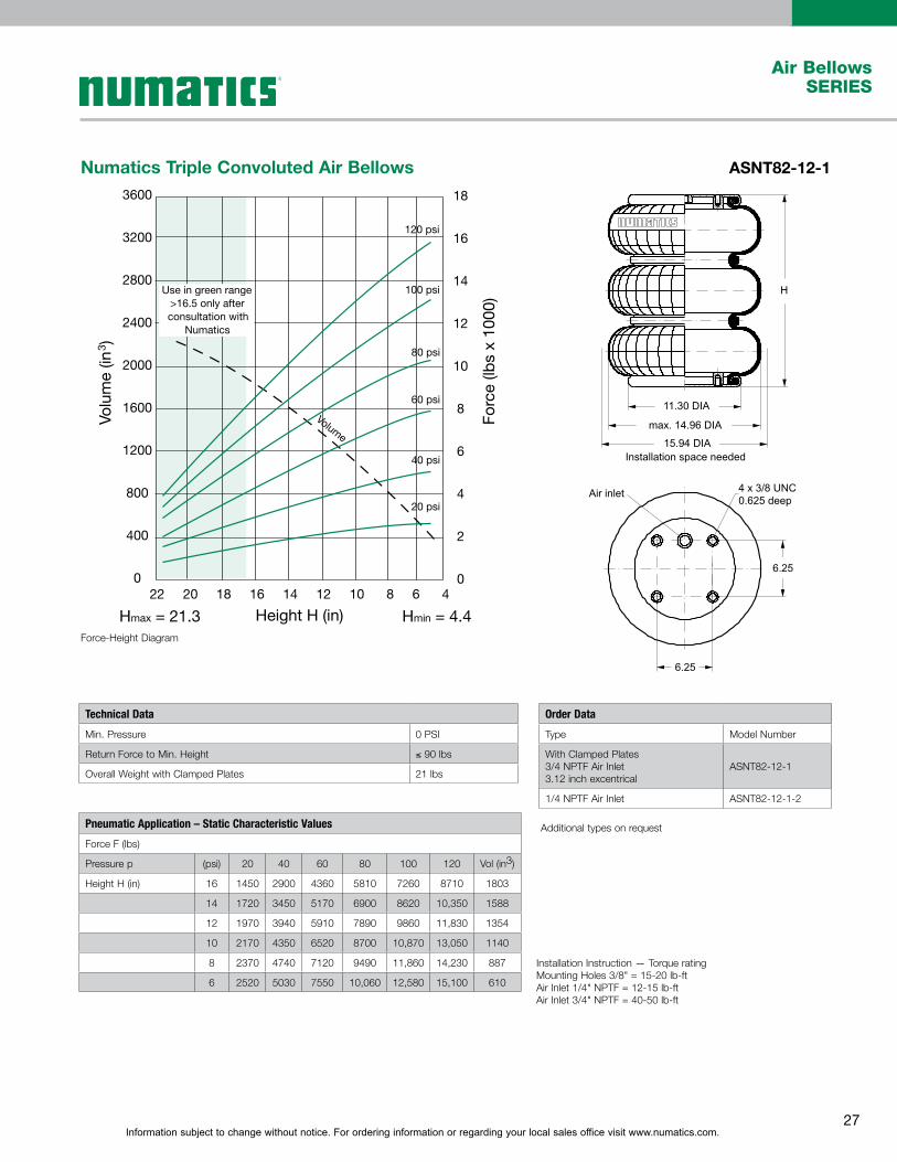
Numatics Triple Convoluted Air Bellows ASNT82-12-1
Hmax = 21.3 Hmin = 4.4Height H (in)
3600
3200
2800
2400
2000
1600
1200
800
400
0
18
16
14
12
10
8
6
4
2
022 20 18 16 14 12 10 8 6 4
Volu
me
(in3 )
Forc
e (lb
s x
1000
)Use in green range>16.5 only afterconsultation with
Numatics
120 psi
100 psi
80 psi
60 psi
40 psi
20 psi
Volume
�������������������������
��������� ����� �������������
���������
��������������
���������
�
����
����
Force-Height Diagram
Additional types on request
Order Data
Type Model Number
With Clamped Plates3/4 NPTF Air Inlet3.12 inch excentrical
ASNT82-12-1
1/4 NPTF Air Inlet ASNT82-12-1-2
Installation Instruction — Torque ratingMounting Holes 3/8" = 15-20 lb-ftAir Inlet 1/4" NPTF = 12-15 lb-ftAir Inlet 3/4" NPTF = 40-50 lb-ft
Technical Data
Min. Pressure 0 PSI
Return Force to Min. Height ≤ 90 lbs
Overall Weight with Clamped Plates 21 lbs
Pneumatic Application – Static Characteristic Values
Force F (lbs)
Pressure p (psi) 20 40 60 80 100 120 Vol (in3)
Height H (in) 16 1450 2900 4360 5810 7260 8710 1803
14 1720 3450 5170 6900 8620 10,350 1588
12 1970 3940 5910 7890 9860 11,830 1354
10 2170 4350 6520 8700 10,870 13,050 1140
8 2370 4740 7120 9490 11,860 14,230 887
6 2520 5030 7550 10,060 12,580 15,100 610

Information subject to change without notice. For ordering information or regarding your local sales office visit www.numatics.com.28
Air BellowsSERIES
Numatics Triple Convoluted Air Bellows ASNT154-12-1
Hmax = 17.7 Hmin = 4.5Height H (in)
Volume1500
2000
2500
3000
1000
500
0
Vol
ume
(in3 )
Forc
e (lb
s x
1000
)
120 psi
100 psi
80 psi
60 psi
40 psi
20 psi
5
10
15
20
25
30
0
18 16 14 12 10 68 4
Use in green range>15.9 only after
consultation withNumatics
Recommended height forVibration Isolation
max. 18.2 DIA
15.12 DIA
20.1 DIAInstallation space needed
13.8 DIA
H
18 x 3/8-24 UNF
1.1
2
Force-Height Diagram
Installation Instructions - torque ratingMounting holes - 3/8” = 28-32 lb-ft
Additional types on request
Technical Data
Min. Pressure 0 PSI
Return Force to Min. Height ≤ 135 lbs
Overall Weight with Clamped Plates 21 lbs
Vibration Isolation – Dynamic Characteristic Values
Design Height H: Recommended 13 Inch, Minimum 12.4 Inch
Pressure p (psi) 40 60 80 100 120 Vol (in3)
Force (Load) (lbs) 5770 8650 11530 14420 17300 –
Spring Rate (lbs/in) 1144 1659 2079 2610 3029 2125
Natural Frequency (Hz) 1.4 1.3 1.3 1.3 1.3 –
Pneumatic Application – Static Characteristic Values
Force F (lbs)
Pressure p (psi) 20 40 60 80 100 120 Vol (in3)
Height H (in) 15 2420 4830 7250 9670 12080 14500 2368
13 2880 5770 8650 11530 14420 17300 2125
11 3270 6530 9800 13070 16330 19600 1846
9 3560 7130 10690 14250 17820 21380 1511
7 3830 7650 11480 15300 19130 22950 1161
Order Data
Type Model Number
Bellow with bead rings,1 7/8 bolts, nuts and washers
ASNT154-12-1

Information subject to change without notice. For ordering information or regarding your local sales office visit www.numatics.com.29
Air BellowsSERIES
Numatics Sleeve Type Air Spring ASNC2-1-1
0,00
0,05
0,10
0,15
0,20
0,25
0,30
0,35
0,40
1,21,41,61,82,02,22,4
Height H [in]
For
ce [L
BS
x 1
000]
0
1
2
3
4
5
6
7
8
Vo
lum
e [i
n3]
Use in dotted range >2.2 in only after consultation with Numatics
Recommended height forvibration isolation: 1.8 in
20 psi
40 psi
60 psi
80 psi
100 psi
120 psi
Hmax=2.5 Hmin=1.2
2.76 DIA
1
5/8-11 UNC
1.34 DIA
1.34 DIA
Installation space needed
5/16-18U NC,0.27 deep
H
m
Air
inle
tax. 2. 34 DIA
Force-Height Diagram
Installation Instruction —Torque rating5/16-18 UNC = 2-4 lb-ft5/8-11 UNC = 8-10 lb-ft1/8 NPTF = Handtight plus one turn.
Additional types on request
Technical Data
Min. Pressure 0 PSI
Return Force to Min. Height ≤ 5 lbs
Overall Weight with Clamped Plates 0.5 lbs
Order Data
Type Model Number
With 1/8 NPTF Air Inlet ASNC2-1-1
Vibration Isolation – Dynamic Characteristic Values
Design Height H: Recommended 1.8 Inch, Minimum 1.4 Inch
Pressure p (psi) 40 60 80 100 120 Vol (in3)
Force (Load) (lbs) 88 132 176 220 264
Spring Rate (lbs/in) 110 154 195 231 272 4.0
Natural Frequency (Hz) 3.5 3.4 3.3 3.2 3.2
Pneumatic Application – Static Characteristic Values
Force F (lbs)
Pressure p (psi) 20 40 60 80 100 120Vol (in3)
Height H (in) 2.2 31 62 92 123 154 185 4.7
1.8 44 88 132 176 220 264 4.0
1.4 52 104 156 208 260 312 3.3

Information subject to change without notice. For ordering information or regarding your local sales office visit www.numatics.com.30
Air BellowsSERIES
Numatics Sleeve Type Air Bellows ASNC6-1-1
For c
e (lb
s x
1000
)
Recommended height for Vi bration Isolation
Force-Height Diagram
Installation Instruction – Torque ratingMounting Stud 5/16” = 2-4 lb x ft5/8” - 11 UNC = 8-10 lb x ftAir Inlet 1/8” NPTF = Handtight plus one turn
Technical Data
Min. Pressure 0 PSI
Return Force to Min. Height ≤ 34 lbs
Overall Weight with Clamped Plates 0.7 lbs
Vibration Isolation – Dynamic Characteristic Values
Design Height H: Recommended 13 Inch, Minimum 12.4 Inch
Pressure p (psi) 40 60 80 100 120 Vol (in3)
Force (Load) (lbs) 220 330 440 550 660 –
Spring Rate (lbs/in) 171 242 315 377 443 9
Natural Frequency (Hz) 2.7 2.7 2.7 2.6 2.6 –
Pneumatic Application – Static Characteristic Values
Force F (lbs)
Pressure p (psi) 20 40 60 80 100 120 Vol (in3)
Height H (in) 3 90 170 260 340 430 510 12
2.5 110 210 320 430 530 640 10
2 110 230 340 460 570 690 7
Order Data
Type Model Number
With 1/8” NPTF Air Inlet - Brass Stud ASNC6-1-1

Information subject to change without notice. For ordering information or regarding your local sales office visit www.numatics.com.31
Air BellowsSERIES
Numatics Sleeve Type Air Bellows ASNC6-2-1
Hmax = 4.33 Hmin = 1.5Height H (in)
Volume
12
16
20
24
28
8
4
0
Vol
ume
(in3 )
Forc
e (lb
s x
1000
)120 psi
100 psi
80 psi
60 psi
40 psi
20 psi
0.2
0.4
0.8
0.6
1.0
1.2
1.4
0.0
4.50 4.00 3.50 3.00 2.002.50 1.50
Use in green range>3.94 only after
consultation withNumatics
Recommended height forVibration Isolation
Force-Height Diagram
Installation Instruction – 5/16-18 UNC = 2-4 lb-ft5/8-11 UNC = 8-10 lb-ft1/8 NPTF = Handtight plus one turn
Note:The dotted lines on the static load curves shows the force of the ASNC6-2-1 with an additional 0.6inch. pedestal under the piston.This pedestal is NOT provided by Numatics. If this pedestal is not used, then the bellow will contact the ground at a height of approx.2.2inch. This should be avoided because it could cause wear at the bellow. Minimum pressure for service without pedestal is 45psi.
Technical Data
Min. Pressure 0 PSI
Return Force to Min. Height ≤ 34 lbs
Overall Weight with Clamped Plates 0.66 lbs
Vibration Isolation – Dynamic Characteristic Values
Design Height H: Recommended 2.95 Inch, lateral guidance necessary
Pressure p (psi) 40 60 80 100 120 Vol (in3)
Force (Load) (lbs) 230 340 460 570 690 –
Spring Rate (lbs/in) 159 221 272 310 363 15
Natural Frequency (Hz) 2.7 2.5 2.4 2.3 2.3 –
Pneumatic Application – Static Characteristic Values
Force F (lbs)
Pressure p (psi) 20 40 60 80 100 120 Vol (in3)
Height H (in) 3.5 100 210 310 420 520 630 17.2
3 110 230 340 460 570 80 14.9
2.5 120 240 360 470 590 710 12.5
Order Data
Type Model Number
With 1/8" NPTF Air Inlet - Brass Stud ASNC6-2-1

Information subject to change without notice. For ordering information or regarding your local sales office visit www.numatics.com.32
Air BellowsSERIES
Numatics Sleeve Type Air Bellows ASNC6-3-1
For c
e (lb
s x
1000
)
Volume
40
35
30
5.9
25
20
15
10
5
0 6.5 6.0 5.5 5.0 4.5 4.0 3.5 3.0 2.5
0.8
0.7
0.6
0.5
0.4
0.3
0.2
0.1
0.0
H ma x = 6.3 H mi n = 2.6 Height H (in)
max. 3.95 DIA
H
4.7 DIA
Installation space required
5/8-11UNC Air Inlet
2.4 DIA
Force-Height Diagram
Installation Instruction 5/8-11 UNC = 8-10 lb-ft1/8 NPTF = Handtight plus one turn
Technical Data
Min. Pressure 5 PSI
Return Force to Min. Height ≤ 34 lbs
Overall Weight with Clamped Plates 0.9 lbs
Pneumatic Application – Static Characteristic Values
Force F (lbs)
Pressure p (psi) 20 40 60 80 100 120 Vol (in3)
Height H (in) 3 130 270 400 540 670 800 10
3.5 130 260 400 530 660 790 13
4 130 260 390 520 650 780 16
4.5 120 240 360 480 500 720 19
5 100 210 310 420 520 630 23
5.5 80 160 240 320 400 480 25
Order Data
Type Model Number
With 1/8" NPTF Air Inlet -Brass Stud at both ends
ASNC6-3-1
Information subject to change without notice. For ordering information or regarding your local sales office visit www.numatics.com.33
Air BellowsSERIES
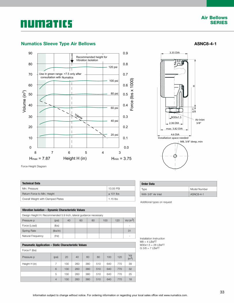
Numatics Sleeve Type Air Bellows ASNC8-4-1
Hmax = 7.87 Hmin = 3.75Height H (in)
Volume
90
80
70
60
50
40
30
20
10
0
0.9
0.8
0.7
0.6
0.5
0.4
0.3
0.2
0.1
0.0
Vol
ume
(in3 )
Forc
e (lb
s x
1000
)
120 psi
100 psi
80 psi
60 psi
40 psi
20 psi
Recommended height forVibration Isolation
8 7 6 5 4 3
Use in green range >7.5 only afterconsultation with Numatics
Air Inlet
3.35 DIA
0.7
1H
2.36 DIA
max. 3.82 DIA
3/8”
M30x1.5
4.6 DIAInstallation space needed
M8, 3/8” deep, min
Force-Height Diagram
Installation Instruction M8 = 4 LBxFTM30x1.5 = 28 LBxFTG 3/8 = 7 LBxFT
Additional types on request
Technical Data
Min. Pressure 13.05 PSI
Return Force to Min. Height ≤ 101 lbs
Overall Weight with Clamped Plates 1.15 lbs
Order Data
Type Model Number
With 3/8" Air Inlet ASNC8-4-1
Vibration Isolation – Dynamic Characteristic Values
Design Height H: Recommended 5.9 Inch, lateral guidance necessary
Pressure p (psi) 40 60 80 100 120 Vol (in3)
Force (Load) (lbs) -
Spring Rate (lbs/in) 31
Natural Frequency (Hz) -
Pneumatic Application – Static Characteristic Values
Force F (lbs)
Pressure p (psi) 20 40 60 80 100 120Vol (in3)
Height H (in) 7 130 260 380 510 640 770 39
6 130 260 380 510 640 770 32
5 130 260 380 510 640 770 25
4 130 260 380 510 640 770 18

World Class Supplier of Pneumatic Components
World Headquarters
Numatics, Inc. | Tel (248) 596-3200 | www.numatics.com | email: [email protected] Rev 1/13 10M-IPC-1/09© Numatics Inc. 2009 - 2013Numatics® is registered in the United States and elsewhere
USA Numatics, Incorporated46280 Dylan DriveNovi, Michigan 48377
P: 248-596-3200 F: 248-596-3201
Canada Numatics, LtdP: 519-758-2700 F: 519-758-5540
Brazil Ascoval Ind.e Comercio LtdaP: (55) 11-4208-1700 F: (55) 11-4195-3970
México - Ascomatica SA de CVP: 52 55 58 09 56 40 (DF y Area metropolitana)P: 01 800 000 ASCO (2726) (Interior de la República) F: 52 55 58 09 56 60