air accident investigation unit ireland - aaiu.ie 2015-001... · air accident investigation unit...
TRANSCRIPT

Air Accident Investigation Unit
Ireland
SYNOPTIC REPORT
ACCIDENT Beechcraft Duchess 76, EI-BUN
Weston Airport, Co. Kildare 20 September 2013

Beechcraft Duchess 76 EI-BUN Weston Airport 20 September 2013
FINAL REPORT
Air Accident Investigation Unit Report 2015 -001
1
This safety investigation is exclusively of a technical nature and the Final Report reflects the determination of the AAIU regarding the circumstances of this occurrence and its probable cause(s). In accordance with the provisions of Annex 131 to the Convention on International Civil Aviation, Regulation (EU) No 996/20102 and Statutory Instrument No. 460 of 20093, safety investigations are in no case concerned with apportioning blame or liability. They are independent of, separate from and without prejudice to any judicial or administrative proceedings to apportion blame or liability. The sole objective of this safety investigation and Final Report is the prevention of accidents and incidents. Accordingly, it is inappropriate that AAIU Reports should be used to assign fault or blame or determine liability, since neither the safety investigation nor the reporting process has been undertaken for that purpose. Extracts from this Report may be published providing that the source is acknowledged, the material is accurately reproduced and that it is not used in a derogatory or misleading context.
1 Annex 13: International Civil Aviation Organization (ICAO), Annex 13, Aircraft Accident and Incident
Investigation. 2 Regulation (EU) No 996/2010 of the European Parliament and of the Council of 20 October 2010 on the
investigation and prevention of accidents and incidents in civil aviation. 3 Statutory Instrument (SI) No. 460 of 2009: Air Navigation (Notification and Investigation of Accidents, Serious
Incidents and Incidents) Regulations 2009.
Foreword

2
2
AAIU Report No: 2015-001 State File No: IRL00913090
Report Format: Synoptic Report
Published: 21/01/2015
In accordance with Annex 13 to the Convention on International Civil Aviation, Regulation (EU) No 996/2010 and the provisions of SI 460 of 2009, the Chief Inspector of Air Accidents, on 20 September 2013, appointed Mr Paddy Judge as the Investigator-in-Charge to carry out an Investigation into this accident. Due to the retirement of Mr Judge, Mr John Owens, an Inspector of Air Accidents, was appointed to complete the Investigation and prepare a Report.
4 UTC: Co-ordinated Universal Time. (One hour behind local time on the day of the accident). All times in this report
are UTC.
Aircraft Type and Registration: Beechcraft Duchess 76, EI-BUN Number and Type of Engines: 1 x Lycoming O-360-A1G6D, 1 x Lycoming LO-360-
A1G6D Aircraft Serial Number: ME-371
Year of Manufacture: 1980
Date / Time (UTC):4 20 September 2013 @ 17.03 hrs
Location:
Weston Airport (EIWT)
Type of Operation:
General Aviation – Training
Persons on Board:
Pilot Instructor - 1 Student - 1
Injuries:
Pilot Instructor - Nil Student - Nil
Nature of Damage: Substantial Commander’s Licence:
Commercial Pilot Licence (CPL) Aeroplanes (A) issued by the Irish Aviation Authority (IAA)
Commander’s Details:
Male, aged 50 years
Commander’s Flying Experience:
5,403 hours of which 1,187 were on type
Notification Source: Aircraft Operator
Information Source: AAIU Accident Report Form submitted by Pilot AAIU Field Investigation

Beechcraft Duchess 76 EI-BUN Weston Airport 20 September 2013
FINAL REPORT
Air Accident Investigation Unit Report 2015 -001
3
SYNOPSIS During the landing roll at EIWT following a series of circuits, the left hand main landing gear on the twin-engined training aircraft collapsed. This caused the aircraft to veer to the left and depart the side of the runway before coming to rest in the grass adjacent to the runway. The aircraft sustained substantial damage. The two occupants were uninjured.
FACTUAL INFORMATION 1.
History of Flight 1.1 At 16.15 hrs on 20 September 2013, with an Instructor and Student on board, the aircraft departed EIWT for a series of training circuits. The purpose of the flight was to allow revalidation of the multi-engine instrument rating on the Student’s licence. Five uneventful circuits were completed on Runway (RWY) 25 and on the sixth circuit, a full-stop landing was planned. The Student who was the Pilot Flying (PF) reported that the aircraft “touched down normally” but that a “pop” was heard during the landing roll, which was followed by the collapse of the left hand (L/H) main landing gear. The aircraft initially continued down RWY 25 in a straight line before it veered left and entered the grass-covered surface adjacent to the runway. It turned through approximately 120o and came to rest on a heading of 130o magnetic (Photo No. 1). Neither occupant was injured and both were able to exit the aircraft unaided.
Photo No. 1: Final resting position of EI-BUN in the grass adjacent to RWY 25.

4
4
Damage to Aircraft 1.2
When the L/H main landing gear collapsed, the L/H propeller contacted the runway which resulted in damage to the tips of both propeller blades. Damage was also caused to the following areas:
L/H main landing gear assembly
L/H flap assembly and the outboard flap attachment
L/H outboard area of the aileron and the trailing edge of the L/H wing skin
Aircraft access step on the L/H side
Tail cone
Personnel Information 1.3
The Instructor held a CPL with a Multi-Engine Instrument Rating (ME IR) and had a total flying experience of 5,403 hours, of which 1,187 were on type. The Student also held a CPL with a total flying experience of 379 hours, of which 32 hours were on type.
Meteorological Information 1.4 Weather conditions at the time of the occurrence were as follows: Wind 250 degrees at 10 kts, clouds ‘few’ at 4,000 feet, temperature 16o C, visibility greater than 10 Kilometres. The runway was dry.
Aircraft Information 1.5
1.5.1 General EI-BUN, a Beechcraft Duchess 76, was manufactured in 1980. It is an all-metal low-wing monoplane with a T-tail and retractable tricycle undercarriage and is fitted with four seats. It is powered by two piston engines; one Lycoming O-360-A1G6D (clockwise rotating) on the port wing and one LO-360-A1G6D (counter-clockwise rotating) on the starboard wing, each fitted with a constant-speed, two-bladed, aluminium alloy Hartzell propeller. The maximum take-off weight is 3,900 lbs (1,769 kgs). The most recent Airworthiness Review Certificate issued before the occurrence was certified on 10 November 2011. This was extended on 9 November 2012 and was valid until 9 November 2013. The total number of aircraft hours flown at the time of the occurrence, as recorded in the aircraft logbook, was 6,108.
1.5.2 Main Landing Gear In the case of each main landing gear (Photo No. 2), a main wheel (Item No. 1) is fitted to a suspension fork (Item No. 2) which is free to pivot at a pivot pin (Item No. 3). A shock absorber pin (Item No. 4) connects the suspension fork to two lugs which are part of the lower end of the shock absorber (Item No. 5). The shock absorber pin is secured to the suspension fork by a flathead pin (Item No. 6) which is retained by a split pin. The flathead pin prevents movement between the shock absorber pin and the suspension fork.

Beechcraft Duchess 76 EI-BUN Weston Airport 20 September 2013
FINAL REPORT
Air Accident Investigation Unit Report 2015 -001
5
However, the compression and extension of the shock absorber during normal operation causes some back and forth rotational movement of the shock absorber about the fixed shock absorber pin. Bushings are installed in the lower lugs of the shock absorber to facilitate this movement (Item No. 7 – highlighted in yellow, two per shock absorber).
Photo No. 2: L/H Main Landing Gear on a serviceable Beechcraft 76. Bushing highlighted in yellow.
Aircraft Examination 1.6
When the aircraft was examined by the Investigation following the occurrence, it was found that the flathead pin had failed in the L/H main landing gear suspension fork, which in turn allowed the shock absorber pin to migrate, resulting in the collapse of the landing gear. Photo No. 3 below was taken during the aircraft recovery operation and shows the L/H main landing gear with the shock absorber pin missing (circled area).
Photo No. 3: L/H main landing gear with shock absorber pin missing.
6
6
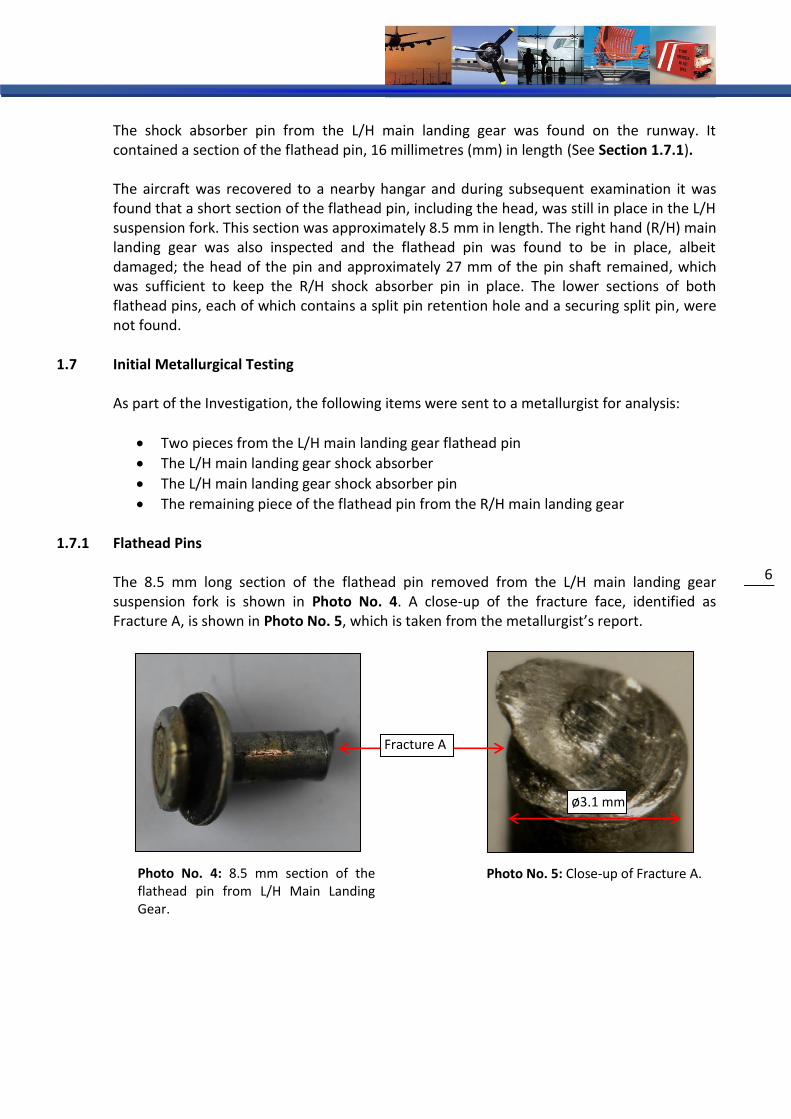
The shock absorber pin from the L/H main landing gear was found on the runway. It contained a section of the flathead pin, 16 millimetres (mm) in length (See Section 1.7.1). The aircraft was recovered to a nearby hangar and during subsequent examination it was found that a short section of the flathead pin, including the head, was still in place in the L/H suspension fork. This section was approximately 8.5 mm in length. The right hand (R/H) main landing gear was also inspected and the flathead pin was found to be in place, albeit damaged; the head of the pin and approximately 27 mm of the pin shaft remained, which was sufficient to keep the R/H shock absorber pin in place. The lower sections of both flathead pins, each of which contains a split pin retention hole and a securing split pin, were not found.
Initial Metallurgical Testing 1.7 As part of the Investigation, the following items were sent to a metallurgist for analysis:
Two pieces from the L/H main landing gear flathead pin
The L/H main landing gear shock absorber
The L/H main landing gear shock absorber pin
The remaining piece of the flathead pin from the R/H main landing gear
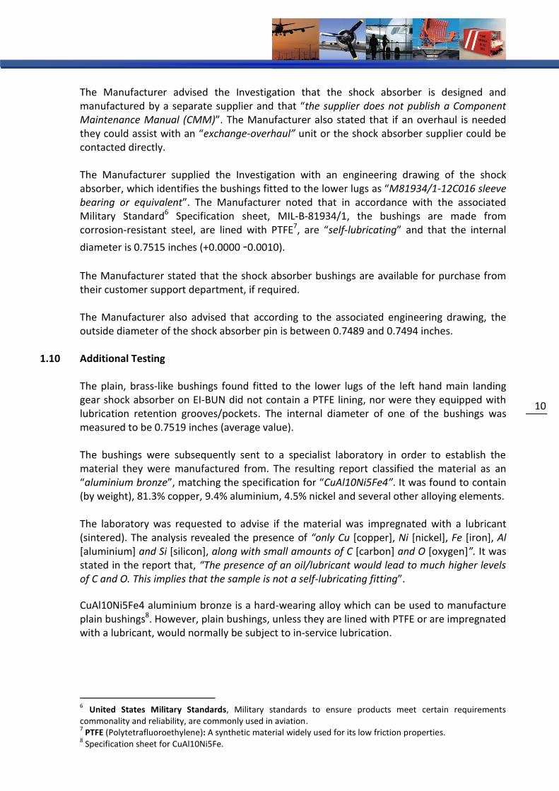
1.7.1 Flathead Pins The 8.5 mm long section of the flathead pin removed from the L/H main landing gear suspension fork is shown in Photo No. 4. A close-up of the fracture face, identified as Fracture A, is shown in Photo No. 5, which is taken from the metallurgist’s report.
Fracture A
ø3.1 mm
Photo No. 4: 8.5 mm section of the flathead pin from L/H Main Landing Gear.
Photo No. 5: Close-up of Fracture A.

Beechcraft Duchess 76 EI-BUN Weston Airport 20 September 2013
FINAL REPORT
Air Accident Investigation Unit Report 2015 -001
7
The 16 mm long section removed from the L/H shock absorber pin is shown in Photo No. 6. The fracture faces on this section are identified as Fracture B and Fracture C. The metallurgist’s report stated that: “The fracture features of Fracture A were those of shear failure, whilst those of Fractures B and C were typical of reversed bending fatigue5 failure. Neither of the Fractures B or C mated with Fracture A. *…+ A piece of the LHS [left hand side] retaining pin is missing from Fracture A to Fracture B or C”.
Photo No. 6: 16 mm long section of flathead pin removed from migrated L/H shock absorber pin.
The flathead pin from the R/H main landing gear suspension fork is shown in Photo No. 7 below, which was also taken from the metallurgist’s report. In relation to this pin, the report stated that: “At a distance 10 mm below the flathead, the pin had suffered partial shearing and at 27 mm below the flathead, the pin was fractured. The fracture features were similar to Fractures B and C in the LHS pin, resulting from reversed bending fatigue”.
Photo No. 7: Flathead Pin from R/H Main Landing Gear.
1.7.2 Shock Absorber Pin The shock absorber pin was also examined by the metallurgist. It was noted that there were circumferential wear marks on the surface (Photo No. 8). In addition, a number of other scratches and marks were found, but the metallurgist considered that they had been caused after the pin migrated. The circumferential wear marks on the pin were in the area which mated with one of the bushings on the lower lugs of the shock absorber (Area No. 1) and also in the area that mated with the suspension fork (Area No. 2). The Investigation measured the outside diameter of the pin and found it to be 0.749 inches.
5 Reverse Bending Fatigue: Fatigue caused by repetitive back and forth bending.
Fracture B Fracture C
Partial shearing

8
8
Photo No. 8: Wear marks on the L/H main landing gear shock absorber pin.
1.7.3 Bushings
Regarding the bushings fitted to the lugs in the lower end of the shock absorber, the metallurgist’s report stated: “There [were] circumferential score marks in both bushings and both had two distinct, deep, lateral (left to right) score marks. The spacing of these marks was similar in both bushings. There was a circumferential track in the LHS bushing and areas that appeared to be a mix of more random scoring/indentation *…+. The cause of the two lateral score marks in each bushing is not known. Some of the damage to the bushings has probably occurred after the fracture of the small retaining pin. However, the similar spacing of the lateral score marks in both bushings is not consistent with damage by the broken retaining pin. It therefore appears that the bushings were scored at some time prior to failure of the small retaining pin. Damage to the bushings and lack of lubrication most probably led to poor rotational movement between the landing gear pin [shock absorber pin] and the bushings which in turn led to fatigue loading of the small retaining pin” (Photos No. 9 and No. 10). It was also noted that “there were remnants of grease in both bushings but this was very dry”.
LHS RHS 44 mm
Circumferential wear marks: (1) At bushing
interface (2) At suspension
fork interface
1 2
Bushing
Photo No. 9: Lower lugs of L/H shock absorber with bushings installed.
Photo No. 10: Scoring on RHS bushing (with bushing removed).

Beechcraft Duchess 76 EI-BUN Weston Airport 20 September 2013
FINAL REPORT
Air Accident Investigation Unit Report 2015 -001
9
Special Airworthiness Information Bulletin 1.8
The Aircraft Manufacturer informed the Investigation that they had “no record of this type of event occurring”. However, the Manufacturer advised that a ‘Service Instruction Letter’ (No. 1073) was issued in relation to a different flathead pin – the pin that retains the suspension fork pivot pin in the suspension fork. The service instruction required that particular flathead pin to be replaced with a larger diameter pin. It was subsequently established by the Investigation that the United States Federal Aviation Administration (FAA) published a ‘Special Airworthiness Information Bulletin’, reference number CE-01-31, on 13 July 2001. This Bulletin specifically relates to the bushings fitted to the lower lugs and the flathead pins which secure the shock absorber pin on Beechcraft 76 aircraft. It is stated in the Bulletin that: “The FAA has received service difficulty reports of broken clevis [flathead] pins, missing connecting [shock absorber] pins and/or severely worn bushings at the lower attachment point of the MLG [Main Landing Gear] shock absorber. Severe wear in the self-lubricated bushings in the shock absorber can create excess friction between the connecting pin and the bushings, which may cause the pin to turn and break the clevis pin that retains it. In one instance, a broken clevis pin allowed the connecting pin to work loose and fall out. This caused the fork portion of the MLG to fold up, which jammed the tire, resulting in the aircraft pulling off the runway where it sustained wing and propeller damage”. In the Bulletin, the FAA recommended that during scheduled 100 hour inspections, the bushings be inspected for excessive wear, the flathead pins inspected for satisfactory condition and the shock absorber pin inspected for correct position. Detailed instructions on how to carry out these inspections were included. In addition, it is recommended in the Bulletin that if any of the inspections revealed abnormalities, “the FAA strongly recommends removal of the shock absorber and close inspection of the connecting [shock absorber] pin, clevis [flathead] pin and bushings, and replacement of these items as necessary”. It is noted on the Bulletin that it is for “information only” and that “recommendations are not mandatory”.
Correspondence with Aircraft Manufacturer and Associated Documentation 1.9
The Manufacturer’s Aircraft Maintenance Manual (AMM) contains procedures for the removal, installation and servicing of the shock absorbers, but not for their overhaul. Instructions for the replacement of the bushings are not included. The main landing gear components are depicted in the Manufacturer’s Illustrated Parts Catalogue (IPC); the shock absorber, the lower shock absorber pin, the flathead pin, associated washer and split pin are all identified and the part numbers for each item are included. However, the bushings fitted to the lower lugs are not identified and consequently a part number is not listed.
1
10
The Manufacturer advised the Investigation that the shock absorber is designed and manufactured by a separate supplier and that “the supplier does not publish a Component Maintenance Manual (CMM)”. The Manufacturer also stated that if an overhaul is needed they could assist with an “exchange-overhaul” unit or the shock absorber supplier could be contacted directly. The Manufacturer supplied the Investigation with an engineering drawing of the shock absorber, which identifies the bushings fitted to the lower lugs as “M81934/1-12C016 sleeve bearing or equivalent”. The Manufacturer noted that in accordance with the associated Military Standard6 Specification sheet, MIL-B-81934/1, the bushings are made from corrosion-resistant steel, are lined with PTFE7, are “self-lubricating” and that the internal
diameter is 0.7515 inches (+0.0000 -0.0010).
The Manufacturer stated that the shock absorber bushings are available for purchase from their customer support department, if required. The Manufacturer also advised that according to the associated engineering drawing, the outside diameter of the shock absorber pin is between 0.7489 and 0.7494 inches.
Additional Testing 1.10 The plain, brass-like bushings found fitted to the lower lugs of the left hand main landing gear shock absorber on EI-BUN did not contain a PTFE lining, nor were they equipped with lubrication retention grooves/pockets. The internal diameter of one of the bushings was measured to be 0.7519 inches (average value). The bushings were subsequently sent to a specialist laboratory in order to establish the material they were manufactured from. The resulting report classified the material as an “aluminium bronze”, matching the specification for “CuAl10Ni5Fe4”. It was found to contain (by weight), 81.3% copper, 9.4% aluminium, 4.5% nickel and several other alloying elements. The laboratory was requested to advise if the material was impregnated with a lubricant (sintered). The analysis revealed the presence of “only Cu [copper], Ni [nickel], Fe [iron], Al [aluminium] and Si [silicon], along with small amounts of C [carbon] and O [oxygen]”. It was stated in the report that, “The presence of an oil/lubricant would lead to much higher levels of C and O. This implies that the sample is not a self-lubricating fitting”.
CuAl10Ni5Fe4 aluminium bronze is a hard-wearing alloy which can be used to manufacture plain bushings8. However, plain bushings, unless they are lined with PTFE or are impregnated with a lubricant, would normally be subject to in-service lubrication.
6 United States Military Standards, Military standards to ensure products meet certain requirements commonality and reliability, are commonly used in aviation. 7 PTFE (Polytetrafluoroethylene): A synthetic material widely used for its low friction properties.
8 Specification sheet for CuAl10Ni5Fe.
Beechcraft Duchess 76 EI-BUN Weston Airport 20 September 2013
FINAL REPORT
Air Accident Investigation Unit Report 2015 -001
11
Component Maintenance Requirements 1.11
Within Europe, the maintenance of aircraft and aircraft components must be performed in accordance with the requirements of the European Aviation Safety Agency (EASA) which are enshrined in legislation. An organisation overhauling components belonging to aircraft weighing less than 5,700 kgs must be appropriately approved in accordance with EASA Part M, Sub-part F (M.A. 601-619). Maintenance on aircraft weighing more than 5,700 kgs, on aircraft involved in commercial air transport and on components belonging to such aircraft, must be performed by an organisation approved in accordance with EASA Part 145. Such organisations can also perform maintenance on aircraft weighing less than 5,700 kgs and on components from such aircraft, subject to specific approval. With reference to EASA Part 145.A.20, ‘Terms of Approval’, the specific components that an Maintenance/Repair Organisation (MRO) is approved to overhaul are listed in the organisation’s exposition9. Approval is only granted by an Airworthiness Authority, subject to the necessary capability being in place, in terms of facilities, equipment, technical data, manpower and training. There are similar requirements for Part M, Sub-part F organisations.
Maintenance History 1.12
The aircraft was maintained in accordance with an IAA Approved Maintenance Program (AMP), which incorporates the Manufacturer’s recommended maintenance schedule. The AMP is based on a 300 hour/ one year, 12 check cycle with an inspection carried out every 25 hours.
Following an accident which occurred to EI-BUN on the 4 June 2009 (AAIU Investigation Report 2010-01), the aircraft was removed from service until November 2011. The L/H and R/H hand main landing gear shock absorbers were removed from the aircraft by the Aircraft Operator during this time and were sent to a UK-based MRO to arrange for their overhaul. This MRO subsequently sent the units to another UK-based MRO, where the units were overhauled. The MRO where the shock absorbers were overhauled was approved in accordance with EASA Part 145 by the UK Civil Aviation Authority (CAA). With the assistance of the UK CAA, the Investigation established that the MRO’s approval did not extend to the overhaul of landing gear components. Notwithstanding this, the MRO’s ‘Defect Rectification Sheet’ for each shock absorber included the instruction to “O/H [overhaul] and renew bushings *…+”. An EASA Part 145 Certificate of Release to Service (CRS) for the work was completed by the MRO on 31 May 2011. In accordance with EASA Part 145, a certification document known as an EASA Form 1 should be issued by an MRO to release overhauled or repaired components. The workpack associated with the work carried out to the shock absorbers did not include an EASA Form 1.
9 Maintenance Organisation Exposition (MOE): A document which describes the structure, approval basis and
operating procedures of an Approved Maintenance Organisation.

1
12
The ‘Invoice Backing Sheet’ attached to the workpack, listed the parts used and charged for by the MRO. This sheet included parts that would typically be used during the overhaul of shock absorbers, including O-Ring seals, scraper rings, hydraulic oil and nitrogen gas. Only one bushing was listed on the sheet. However, there is one bushing installed in each lug at the lower end of each shock absorber (two per shock absorber, four in total). A part number for the bushing was not included. With the assistance of an Accredited Representative from the UK’s Air Accidents Investigation Branch (AAIB), the MRO where the shock absorbers were overhauled was requested to provide further information regarding the replacement of the shock absorber bushings. The MRO reported that the bushings were received with the shock absorbers. However, the Operator and the MRO where the shock absorbers were initially sent stated that replacement bushings were not supplied by them when the units were sent for overhaul. The Operator refitted the shock absorbers to the aircraft during the 2011 annual inspection which was certified on 10 November 2011. At the time of installation, the Operator accepted the documentation that accompanied the unit (a CRS and not a Form 1), as being an acceptable means of certification for the unit. Since that time, the Operator has become a Part 145 approved organisation. The procedures now in place in relation to component receipt (including physical inspection and a review of the associated paperwork) form part of the approved organisation’s Part 145 MOE. The total aircraft hours at the time of shock absorber installation were 5,548. The last annual inspection performed on EI-BUN prior to the occurrence was on 8 November 2012. The annual inspection included a requirement to “Inspect the shock strut and components for condition, attachment, proper inflation and leakage *…+”. A 300 hour inspection was performed on 23 August 2013. The 300 hour inspection included a requirement to “jack airplane as described in Chapter 7 of the Maintenance Manual, check the retractable landing gear for operation and lubricate”. The inspection paperwork indicated that both tasks were completed as required. A 25 hour inspection was performed on 5 September 2013. There are no landing gear related maintenance tasks on the 25 hour inspection. The Operator was not aware of the FAA’s Special Airworthiness Information Bulletin relating to recommended inspections of the shock absorber bushings and flathead pins. Consequently, this Bulletin, which was issued in 2001, was not referred to in the aircraft’s maintenance records. The Operator informed the Investigation that more recent Special Airworthiness Information Bulletins relating to other topics are received and reviewed.
Additional Information 1.13
When the Investigation identified that incorrect bushings were fitted to the L/H main landing gear shock absorber, the Operator was requested to check the bushings on the R/H landing gear and on the landing gears fitted to their other Beechcraft 76 aircraft, to ensure that the correct bushings were fitted.

Beechcraft Duchess 76 EI-BUN Weston Airport 20 September 2013
FINAL REPORT
Air Accident Investigation Unit Report 2015 -001
13
At the time of writing, EI-BUN was not in operation as a result of another occurrence in May 2014. The Investigation inspected EI-BUN and observed that the bushings fitted to the lower lugs of the R/H main landing gear shock absorber appeared to be manufactured from a brass-like material, likely to be aluminum bronze. The Operator was immediately advised of this finding and informed the Investigation that the both main landing gear shock absorbers would be replaced before the aircraft was returned to service. The Investigation noted that during visual inspection of the landing gear, it is possible to see the lower end of the flathead pin, including the retention split pin (Section 1.5.2, Photo No. 2). The upper end of the pin, including the “flathead”, is not readily visible.
ANALYSIS 2.
General 2.1
Laboratory analysis established that the bushings found fitted to the lower lugs of the L/H main landing gear shock absorber were manufactured from aluminium bronze. The correct bushings, as specified in the Aircraft Manufacturer’s engineering drawing are manufactured from corrosion-resistant steel and contain an integral PTFE liner. Lubrication of PTFE-lined bushings is not required and as such, there was no provision for lubrication in this area. Aluminium bronze bushings would normally be lubricated in service. However, the aluminium bronze bushings found fitted were not impregnated with a lubricant, nor did they contain lubrication retention grooves/pockets. There was some evidence of dried grease on the bushings, but this may have been used during installation of the shock absorber. The internal diameter of one of the bushings fitted was measured by the Investigation and found to have an average value of 0.7519 inches, which is 0.0004 inches larger than the maximum dimension listed on the associated specification sheet (0.7515). The outside diameter of the shock absorber pin was measured to be 0.749 inches, which is within the tolerance specified. The resulting clearance between the shock absorber pin and the bushing was calculated as being 0.0029 inches which is 0.0003 inches greater than the maximum clearance permitted, as calculated from the specifications (0.0026 inches). The Investigation considers that this difference, of less than half of one thousandth of an inch, was unlikely to have been a factor in this occurrence.
The FAA, in their 2001 Special Airworthiness Information Bulletin, reported that severe wear in the correct specification, PTFE-lined bushings can create excess friction between the shock absorber pin and the bushings, which may cause the shock absorber pin to turn and break the flathead pin which retains it. Metallurgical analysis of the failed flathead pin from the L/H main landing gear and the partially failed flathead pin from the R/H gear on EI-BUN is consistent with FAA’s findings, in that it identified that shearing and reversed bending loads caused the damage to the flathead pins on EI-BUN.
The incorrect, non-lubricated aluminium bronze bushings fitted to EI-BUN resulted in increased friction between the bushings and the shock absorber pin, in a similar manner to severely worn PTFE-lined bushings. This increased friction is evidenced by the circumferential score marks on the bushings and on the shock absorber pin.

1
14
The lateral score marks on the bushings may also have contributed to the increased friction, which resulted in rotational forces being exerted on the shock absorber pin and consequently led to fatigue failure due to shearing and reversed bending loads being placed on the flathead pins.
The failure of the L/H flathead pin led to the migration of the shock absorber pin and the collapse of the L/H main landing gear during landing. Following this, directional control was lost and the aircraft exited the side of the runway.
Origin of Incorrect Bushings 2.2 The Operator sent the shock absorbers to an MRO to arrange for their overhaul and this MRO, in turn, sent them to another MRO, where the overhaul was carried out. The MRO where the shock absorbers were overhauled reported that replacement bushings were received with the shock absorbers when the units arrived for overhaul. Furthermore, the invoice issued by the MRO where the shock absorbers were overhauled only listed one bushing, whereas there are four bushings fitted to the lower lugs (two per unit). However, the Operator and the MRO where the shock absorbers were initially sent informed the Investigation that bushings were not supplied by them. Consequently, the Investigation was unable to determine the origin of the incorrect bushings that were fitted to EI-BUN.
Shock Absorber Overhaul 2.3 Instructions for the replacement of the bushings installed in the lower lugs of the main landing gear shock absorbers are not included in the AMM. Furthermore, the Aircraft Manufacturer advised the Investigation that there is no CMM available for the shock absorbers. Approval for the overhaul of specific components is only granted by an Airworthiness Regulatory Authority, subject to the necessary capability being in place, including the availability of technical data such as a CMM. The MRO where the shock absorbers were overhauled was approved by the UK CAA in accordance with EASA Part 145, but the approval did not extend to the overhaul of landing gear components. Accordingly, a Safety Recommendation is made to the UK CAA to review this matter with the MRO.
Safety Recommendation No. 1 It is recommended that the UK Civil Aviation Authority (CAA) should review with the Maintenance/Repair Organisation (MRO), the overhaul and certification of components for which the MRO does not have approval. (IRLD2015001)

Beechcraft Duchess 76 EI-BUN Weston Airport 20 September 2013
FINAL REPORT
Air Accident Investigation Unit Report 2015 -001
15
Aircraft Maintenance Inspections 2.4
The overhauled shock absorbers were fitted to the aircraft during an annual inspection that was certified on 10 November 2011 with the total aircraft operating hours being recorded as 5,548. The aircraft operating hours at the time of the occurrence were 6,108. Therefore, the shock absorbers were installed for a total of 560 hours before the accident occurred.
The aircraft records indicated that all scheduled maintenance inspections were performed as required, including the requirement every 100 hours, to “inspect the shock strut and components for condition and attachment *…+”.
As indicated in Section 1.5.2, Photo No. 2, the lower end of each flathead pin, including the retention split pin can be readily inspected when the aircraft is in its normal configuration. However, it may be difficult to notice when the lower end of a flathead pin along with its retention split pin is missing. Hence, the L/H shock absorber pin may not have been securely retained for a period of time. This is evidenced by the failure of the flathead pin in the R/H main landing gear which did not lead to an immediate migration of its shock absorber pin. It is further evidenced by the circumferential wear marks on the section of the L/H shock absorber pin that mated with the suspension fork (Section 1.7.2, Photo No. 8, Area No 2), which indicate that relative movement may have been occurring here for a period of time. Such movement could only occur if the shock absorber pin was not being retained in the suspension fork by the flathead pin.
The FAA issued a related Special Airworthiness Information Bulletin in July 2001 (CE-01-31). This Bulletin recommended detailed inspection instructions for checking the lower attachment points on the main landing gear shock absorber gears fitted to Beechcraft 76 aircraft. Specific instructions included the inspection of the bushings fitted to the lower lugs of the shock absorbers for excessive wear, how to ensure the integrity of the flathead pins and how to check the security of the shock absorber pin.
In the case of EI-BUN, the failure of the flathead pins was due to the installation of incorrect specification bushings and not due to excessively worn bushings of the correct specification. Nevertheless, the Investigation considers that the detailed inspections recommended by the FAA would identify failures or impending failures of the flathead pins and could reduce the possibility of similar landing gear failures on Beechcraft 76 aircraft. Because the FAA’s Bulletin was issued in 2001, there is a possibility that, similar to the Operator of EI-BUN, not all operators of the aircraft type are aware of its existence. To ensure that all operators of the Beechcraft 76 aircraft are aware of, and regularly conduct the FAA recommended inspections, a Safety Recommendation is made to the Manufacturer to amend the maintenance schedule for the Beechcraft 76 aircraft to include inspections similar to those recommended by the FAA.
Safety Recommendation No. 2 It is recommended that Textron Aviation should consider amending the maintenance schedule for the Beechcraft Duchess 76 aircraft, to include specific inspections of the shock absorber lower attachment point, including the bushings, shock absorber pin and flathead pin, similar to those inspections recommended by the Federal Aviation Administration (FAA) in their Special Airworthiness Information Bulletin number CE-01-31. (IRLD2015002)

1
16
Component Maintenance Manual 2.5
The FAA’s Special Airworthiness Information Bulletin refers to a number of reports of “broken clevis [flathead] pins, missing connecting [shock absorber] pins and/or severely worn bushings” on Beechcraft 76 aircraft. It recommends “removal of the shock absorber and close inspection of the connecting [shock absorber] pin, clevis [flathead] pin and bushings, and replacement of these items as necessary”. Based on the FAA’s findings, the need could arise for the replacement of severely worn bushings. The Aircraft Manufacturer confirmed that spare bushings are available through their customer service department. However, as bushing replacement instructions are not contained in the AMM, it is not possible for an aircraft maintainer to replace the bushings. Similarly, as there is no CMM, it would not be possible for an MRO to obtain appropriate approval from the relevant Airworthiness Authority. In the case of this occurrence, the shock absorbers were overhauled by an MRO whose approval did not extend to the overhaul of such units. Nevertheless, if a CMM was made available it would make it possible for suitable MROs, to apply to the relevant Airworthiness Authority for approval to overhaul Beechcraft Duchess 76 shock absorbers. Accordingly, a Safety Recommendation is issued to the Aircraft Manufacturer to review with the shock absorber manufacturer, the possibility of publishing the necessary technical data.
Safety Recommendation No. 3 It is recommended that Textron Aviation in conjunction with the shock absorber manufacturer should review the possibility of publishing a Component Maintenance Manual (CMM) for the shock absorbers fitted to the Beechcraft Duchess 76 aircraft to include specific procedures for the replacement of the bushings fitted to the lower lugs. (IRLD2015003)
CONCLUSIONS 3.
(a) Findings
1. The aircraft held a valid Airworthiness Review Certificate.
2. Records indicate that all scheduled maintenance was carried out as required.
3. The shock absorbers were overhauled and refitted to the aircraft in 2011.
4. There is no Component Maintenance Manual for the shock absorbers.
5. The Maintenance/Repair Organisation where the shock absorbers were overhauled was not approved to overhaul landing gear components such as shock absorbers.
6. Incorrect specification replacement bushings, which were found to be manufactured from aluminium bronze, were fitted to the lower lugs of the L/H shock absorber.
7. The origin of the incorrect bushings was not established.
Beechcraft Duchess 76 EI-BUN Weston Airport 20 September 2013
FINAL REPORT
Air Accident Investigation Unit Report 2015 -001
17
8. The correct specification bushings are manufactured from corrosion-resistant steel and are lined with self-lubricating PTFE. Consequently, there is no provision or requirement for in-service lubrication of the bushings.
9. Shearing and reverse bending loads resulted in the fatigue failure of the flathead pin which normally secures the L/H main landing gear shock absorber pin.
10. The flathead pin fitted to the R/H main landing gear was also damaged as a result of shearing and bending loads, but remained sufficiently intact to prevent the migration of the associated shock absorber pin.
11. The failure of the L/H flathead pin and the partial failure of the R/H flathead pin were caused by rotational forces being exerted on the shock absorber pins as a result of increased friction between the incorrect specification bushings and the shock absorber pin.
12. The failure of the flathead pin fitted to the L/H main landing gear led to the migration of the shock absorber pin, which in turn resulted in the collapse of the L/H main landing gear.
13. The inspections of the main landing gear, as contained in the Approved Maintenance Programme which incorporates the Manufacturer’s recommended maintenance schedule, may not be sufficient to identify failures or impending failures of the flathead pins.
14. The Aircraft Illustrated Parts Catalogue did not specify a part number for the bushings fitted to the lower lugs of the main landing gear shock absorbers.
15. A visual inspection performed by the Investigation on the installed shock absorber on the R/H main landing gear, noted that the bushings also appeared to be manufactured from a brass-like material, likely to be aluminium bronze and not the correct material.
16. The FAA published a Special Airworthiness Information Bulletin in 2001, relating to excessive wear of the correct specification bushings and the consequential failure of the flathead pins. This Bulletin recommends specific inspections for the prevention and detection of such failures.
(b) Probable Cause
Loss of directional control during the landing roll, due to the collapse of the left hand main landing gear following the migration of the shock absorber pin.
(c) Contributory Factors
1 The MRO where the shock absorbers were overhauled carried out work which was beyond its scope of approval.
2 Incorrect bushings were fitted during overhaul of the shock absorbers which resulted in increased friction between the shock absorber pin and the bushings.

1
18
No.
It is Recommended that: Recommendation Ref.
1. 1It is recommended that the UK Civil Aviation Authority (CAA) should review with the Maintenance/Repair Organisation (MRO), the overhaul and certification of components for which the MRO does not have approval.
IRLD2015001
2. It is recommended that Textron Aviation should consider amending the maintenance schedule for the Beechcraft Duchess 76 aircraft, to include specific inspections of the shock absorber lower attachment point, including the bushings, shock absorber pin and flathead pin, similar to those inspections recommended by the Federal Aviation Administration (FAA) in their Special Airworthiness Information Bulletin number CE-01-31.
IRLD2015002
3. Textron Aviation in conjunction with the shock absorber manufacturer should review the possibility of publishing a Component Maintenance Manual (CMM) for the shock absorbers fitted to the Beechcraft Duchess 76 aircraft to include specific procedures for the replacement of the bushings fitted to the lower lugs.
IRLD2015003
View Safety Recommendations for Report 2015-001
SAFETY RECOMMENDATIONS 4.
- END -

In accordance with Annex 13 to the Convention on International Civil Aviation, Regulation (EU) No 996/2010, and Statutory Instrument No. 460 of 2009, Air Navigation (Notification and Investigation of Accidents, Serious Incidents and Incidents) Regulation, 2009, the sole purpose of this investigation is to prevent aviation accidents and serious incidents. It is not the purpose of any such investigation and the associated investigation report to apportion blame or liability.
A safety recommendation shall in no case create a presumption of blame or liability for an occurrence.
Produced by the Air Accident Investigation Unit
AAIU Reports are available on the Unit website at www.aaiu.ie
Air Accident Investigation Unit, Department of Transport Tourism and Sport, 2nd Floor, Leeson Lane, Dublin 2, Ireland. Telephone: +353 1 604 1293 (24x7): or
+353 1 241 1777 Fax: +353 1 604 1514 Email: [email protected] Web: www.aaiu.ie