aims operating corp., inc., dba aims power - · pdf fileaims operating corp., inc., dba aims...
TRANSCRIPT

AIMS Operating Corp., Inc., dba AIMS Power
Part #: SCC60MPPT
Manual
Introduction
This manual contains instructions on installation, operation, usage and
maintenance of the Solar Charge Controller. Please read carefully before
installing. We recommend consulting professionals if you have any doubt
about the installation process or setup with Solar Panels, Power Inverter
and Batteries. Keep this manual in case you need it for future reference.
Some brief descriptions of Symbols used in this manual are below:
Warning
Damage to equipment or personnel may occur if you do not follow these
instructions
Danger
A hazardous situation may occur, including fire and/or shock, if you do
not pay attention
Attention
Indicates additional data and/or information

Contents
1 Notes on this Manual .. ......................................................................... 1
2 Safety Instructions ................................................................................ 2
3 Unpackaging ......................................................................................... 3
4 Assembly............................................................................................... 4
5 MPPT controller Connections .............................................................. 7
6 LED/LCD and function key…………...............................................10
7 Parameter Settings..............................................................................12
8 MPPT and PC Connections............................................................... 13
9 Technical Parameters..........................................................................18
10 Maintenance and Cleaning............................................................ ....20
11 Storage and disposal……...................................................................21
12 Warranty and Repair..........................................................................21
13 Appendix........................................................................................... 22

1. Notes on this Manual
This manual describes how to install and service your Aims Power MPPT solar
charge controller.
1.1 Validity
This manual applies to MPPT solar charge controller model produced by AIMS
Power. Part # SCC60MPPT
1.2 Target Group
This manual is intended for the installer and the operator.
1.3 All manuals for the device and installed components should be stored in the
immediate vicinity of the charge controller and should be accessible at all times.
1.4 Symbols Used (more)
The following types of safety messages and general information appear in this
document:
Warning!
WARNING indicates a hazardous situation which, if not avoided, could
result in machine stoppage or serious injury.
Warning!
WARNING indicates a hazardous situation which, if not avoided, could
result in machine stoppage or serious injury.
Note!
In order to operate this device well, please read the operation
instructions carefully.

2. Safety Instructions
2.1 General Safety Instructions
2.2 Explanation of Symbols
Below is the explanation for all the symbols shown on the device and label.
Symbol Explanation
Risk of electric shock
Energy stored in capacitors will remain for 5 minutes; don’t touch within this
period after disconnecting
Both input and output lines have power, disconnect both and don’t operate for at
least 5 minutes after disconnection
No self-serviceable parts are inside the enclosure, don’t attempt to remove the
cover.
Only qualified persons are permitted to operate and maintain the equipment.
Only insulated tools are permitted for use to reduce risks of hazard to
individuals.
Caution!
Unit may emit some radiation which may be harmful.
•Do not stay within 1 foot of controller for any extended period of time.
Warning!
The input voltage of this device may be extremely high and life
threatening.
• All work on the charge controller must only be carried out by an electrically
skilled person.
•The Controller is not to be used by children or persons with reduced physical
sensory or mental capabilities, or lack of experience and knowledge, unless
they have been given supervision or instruction.
•Children should be supervised to ensure that they do not play with the
appliance.
Caution!
Surface may be extremely hot and may cause burns.
• Do not touch the enclosure of the charge controller during operation.
If possible keep in a cool environment.
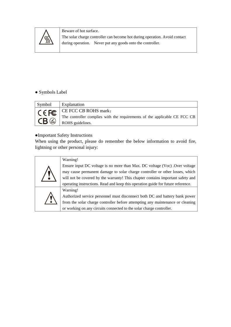
Beware of hot surface.
The solar charge controller can become hot during operation. Avoid contact
during operation. Never put any goods onto the controller.
● Symbols Label
Symbol Explanation
CE FCC CB ROHS mark;
The controller complies with the requirements of the applicable CE FCC CB
ROHS guidelines.
●Important Safety Instructions
When using the product, please do remember the below information to avoid fire,
lightning or other personal injury:
Warning!
Ensure input DC voltage is no more than Max. DC voltage (Voc) .Over voltage
may cause permanent damage to solar charge controller or other losses, which
will not be covered by the warranty! This chapter contains important safety and
operating instructions. Read and keep this operation guide for future reference.
Warning!
Authorized service personnel must disconnect both DC and battery bank power
from the solar charge controller before attempting any maintenance or cleaning
or working on any circuits connected to the solar charge controller.

3. Unpacking
3.1 Parts List:
Object Quantity Description
A 1 unit Charge controller
B 2 pcs & 4 pcs Hang bracket & screws
C 1 pce RS232 to RJ45 comm
cable
D 2 pcs PV input (blue), DC
output (red)
E 1 pce Manual
F 1 pce CD
G 1 pce Bat Temp Sensor
H 2 pcs Spare Fuses
If there are any parts missing, please contact AIMS Power at
[email protected] or (775)359-6703 ext 227.
3.2 Check for Transport Damage
Check the charge controller for visible external damage, such as dents on the
enclosure. Contact AIMS Power at [email protected] or (775)359-6703
ext 227.
3.3 Identifying the Charge Controller
Our charger controller is MPPT and has a max charge rate of 60Amps. It will work
on 12 through 48Vdc battery systems (charge details in sect 5.2.2)
E C A
D
G
F

4. Assembly
4.1 Operator:technical personnel
4.2 Selecting Mounting Location
4.2.1 Dimensions
L * W * H: 10.63*5.91*3.46 in
270mm*150mm*88mm
4.2.2 Net Weight
Weight:6.6Lbs or 3kg
4.2.3 Ambient Conditions
• The mounting location and method must be suitable for the weight and dimensions.
• Mount on a solid surface.
• The mounting location should be accessible at all times.
• The charge controller should be easy to remove from the mounting location at any
time.
• The ambient temperature should be between -4 and 140F (-20 and 60 °C) to
guarantee optimal operation.
• Do not expose the charge controller to direct sunlight to avoid power losses due to
Danger:
Possible fire and explosion hazard
The charge controller enclosure may become hot during operation.
• Do not mount the charge controller on flammable construction material.
• Do not mount the charge controller near highly flammable materials.
• Do not mount the charge controller in potentially explosive areas.
• Do not expose the charge controller to direct sunlight to avoid power
loss due to overheating.
Caution:
Enclosure may become hot to the touch and may cause burns
• Mount the charge controller in such a way that it cannot be touched
inadvertently during operation.

overheating.
4.2.4 Safety Clearance
Observe the following safety clearance to side walls, other devices or objects to
ensure sufficient heat dissipation.
Direction Safety clearance
Sides 8in or 20cm
Top 12in or 30cm
Bottom 8in or 20cm
5. MPPT controller Connection
5.1 Safety
Danger!
High voltages are present and dangerous
• Disconnect the PV array using a disconnection unit and secure it against
accidental reactivation.
• Disconnect the circuit breaker and ensure that it cannot be reconnected.
• Ensure that no voltage is present in the system.
危险!
由于高电压,太阳能充电控制器可能导致生命危险。
•断开光伏阵列应使用断路装置,并避免
意外激活。
•断开断路器,并确保它无法重新连接。
•确保在系统中不存在电压。
Warning:
Risk of injury due to electric shock。
If all cables with different voltages are routed in parallel, damaged cable
insulations may lead to a short circuit.
• Route all cables separately if possible.
Warning:
Over voltage can destroy the system.
• Use an external over voltage protector in areas with an increased risk of
lightning.

5.2 Connections of the PV power system (Batteries must be connected prior to
connecting Solar Panels or damage will occur!)
5.2.1 PV String
Solar panels may be connected in series or in parallel. Since all panels have
different characteristics it is critical to know the specs. We recommend using AIMS
Power solar panels. We will be more able to assist you in your system design.
Open-circuit voltage (Voc) of module arrays connected in series should be less than
Max. DC input Voltage (150V) of the charge controller; operating voltage (Vmax)
should conform to MPPT voltage range.
Please use PV cable to connect modules to the charge controller. It should be outdoor
uv rated and we recommend 10Awg to prevent excessive losses due to distance. It is
beneficial to increase the dc voltage to optimize performance and decrease
inefficiencies.
5.2.2 The voltage and type of battery
1) This controller can charge DC: 12V, 24V and 48V battery systems. It will
automatically recognize the system voltage
Note:
Do not connect the PV panel positive or negative to ground.
Warning:
PV module voltage may be very high! Electrical shock and
fire may result due to improper connections. Please comply
with electric safety rules when connecting.
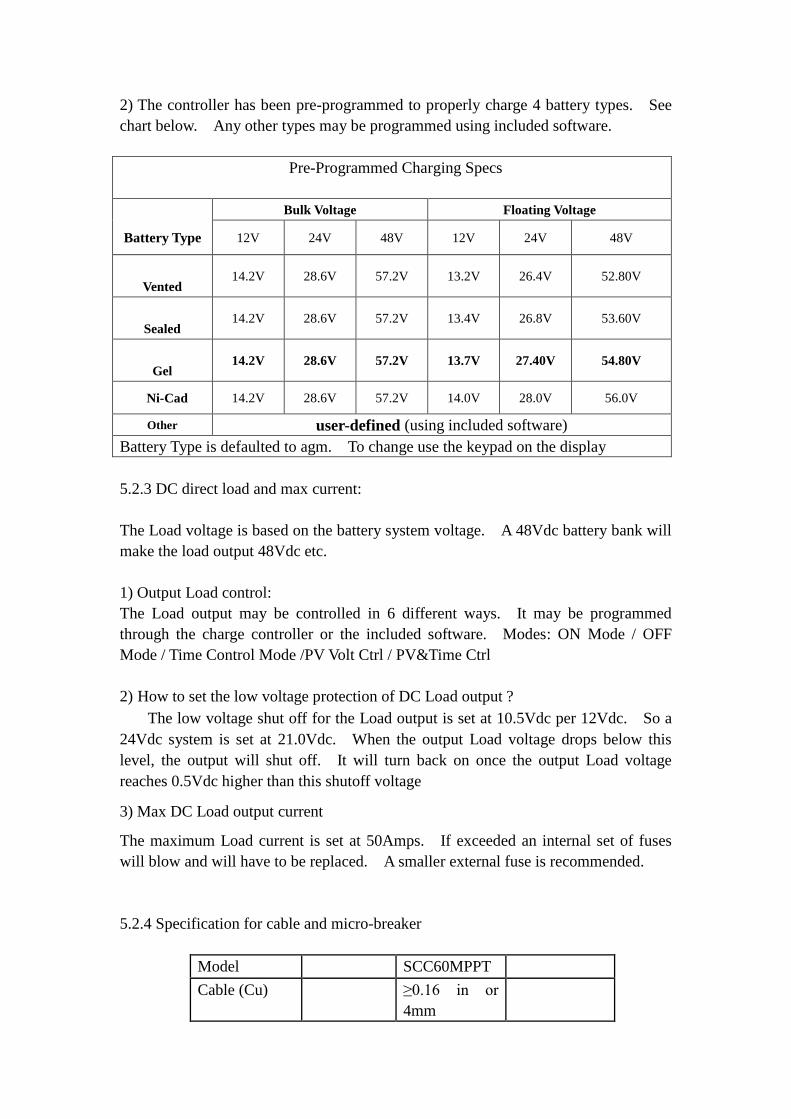
2) The controller has been pre-programmed to properly charge 4 battery types. See
chart below. Any other types may be programmed using included software.
Pre-Programmed Charging Specs
Battery Type
Bulk Voltage Floating Voltage
12V 24V 48V 12V 24V 48V
Vented 14.2V 28.6V 57.2V 13.2V 26.4V 52.80V
Sealed 14.2V 28.6V 57.2V 13.4V 26.8V 53.60V
Gel 14.2V 28.6V 57.2V 13.7V 27.40V 54.80V
Ni-Cad 14.2V 28.6V 57.2V 14.0V 28.0V 56.0V
Other user-defined (using included software)
Battery Type is defaulted to agm. To change use the keypad on the display
5.2.3 DC direct load and max current:
The Load voltage is based on the battery system voltage. A 48Vdc battery bank will
make the load output 48Vdc etc.
1) Output Load control:
The Load output may be controlled in 6 different ways. It may be programmed
through the charge controller or the included software. Modes: ON Mode / OFF
Mode / Time Control Mode /PV Volt Ctrl / PV&Time Ctrl
2) How to set the low voltage protection of DC Load output ?
The low voltage shut off for the Load output is set at 10.5Vdc per 12Vdc. So a
24Vdc system is set at 21.0Vdc. When the output Load voltage drops below this
level, the output will shut off. It will turn back on once the output Load voltage
reaches 0.5Vdc higher than this shutoff voltage
3) Max DC Load output current
The maximum Load current is set at 50Amps. If exceeded an internal set of fuses
will blow and will have to be replaced. A smaller external fuse is recommended.
5.2.4 Specification for cable and micro-breaker
Model SCC60MPPT
Cable (Cu) ≥0.16 in or
4mm

Micro-Breaker 63A
Micro-breaker should be installed between DC input and outputs. Kindly check the
following picture (we do not provide external breakers):
5.2.5 MPPT controller work step
Please make sure the controller is properly wired.
Step 1: Close the battery breaker or make connection with the battery bank. Some
led’s and the lcd should illuminate.
Step 2: Now make the PV connection. If the PV module voltage is in the charging
range, then the controller will start to work .
Step 3: If the DC Load will be used, set to proper settings and make the connection.
5.2.6 Steps for Proper Shutdown
Caution: Follow the steps for shutdown to avoid damage
Caution: Please follow the steps to ensure proper programming

Step 1: Open the PV breaker to disconnect panels from controller.
Step 2: Open the battery breaker or disconnect controller from battery bank. This
will completely shut the controller to off.
6. LED/LCD and function key
6.1 Panel Description
Meaning of LED and function key
ALARM (Red - Alarm indicating a fault
CHARGE (Blue) - Charging indicator
LOAD (Green) - Load Light indicates load output present
UP - UP Function Key for page up and to increase a number
DOWN - DOWN Function for page down and to decrease a number
ENTER - ENTER key to accept an entry
ESC - ESC Key to exit and save data
6.2 Smart Charge Modes
This controller has 3 modes: Constant charging stage ( CC Mode ) , Constant voltage
charging stage ( CV Mode ) , Floating charge stage ( FC Mode ) :
Warning:NEVER disconnect the battery while charging.
This will cause permanent damage to the controller and is not
covered under the warranty. Always disconnect PV panels
first.

In CC Mode the blue led flashes every second.
In CV Mode the blue led flashes every 3 seconds.
In CF Mode the blue led stays on.
(Note: Charging Mode can also be checked via lcd or included s/w)
Menu
No. Menu Type Menu Description
1 Work Status Checks state of charge
2 Setting Parameter set
3 Information Parameter check
6.3.1 Information from lcd display
SMART 2 MPPT LCD INFORMATION Note
Chg Cur(Charge current) If charging, will have
information
Chg Model(Charging Mode) Charging Mode
Time Time
Bat Temp(The real time temperature) If temperature sensing wire is
connected, then it will show
temperature
Work
Status Buck Temp(The main real time temperature)
PV Volt(Solar panel voltage) PV input voltage
Chg Power(Real time charge power ) Charging power
Bat Volt(Battery real time voltage)
Shows battery voltage, if it is
charging, it will show charging
voltage
Will show fault mode under
fault state
Bat Type Sel
Setting
Vented Battery type set
Gel
Nicd
Sealed
User Def
User Bat Set
Bulk Volt Set
Custom, need to set
Main charging voltage and
float charging voltage
Float
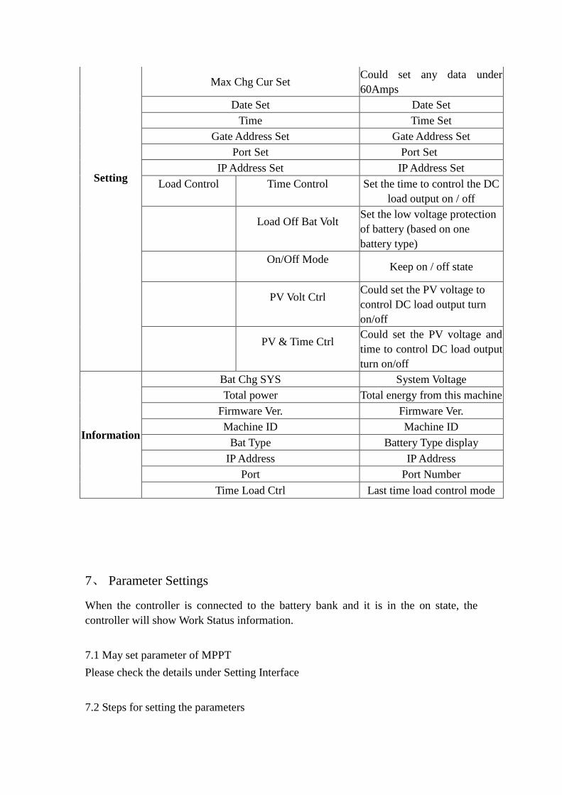
Setting
Max Chg Cur Set Could set any data under
60Amps
Date Set Date Set
Time Time Set
Gate Address Set Gate Address Set
Port Set Port Set
IP Address Set IP Address Set
Load Control
Time Control
Set the time to control the DC
load output on / off
Load Off Bat Volt
Set the low voltage protection
of battery (based on one
battery type)
On/Off Mode
Keep on / off state
PV Volt Ctrl
Could set the PV voltage to
control DC load output turn
on/off
PV & Time Ctrl
Could set the PV voltage and
time to control DC load output
turn on/off
Information
Bat Chg SYS System Voltage
Total power Total energy from this machine
Firmware Ver. Firmware Ver.
Machine ID Machine ID
Bat Type Battery Type display
IP Address IP Address
Port Port Number
Time Load Ctrl Last time load control mode
7、 Parameter Settings
When the controller is connected to the battery bank and it is in the on state, the
controller will show Work Status information.
7.1 May set parameter of MPPT
Please check the details under Setting Interface
7.2 Steps for setting the parameters
Press ESC in main menu ----> Press down to change the page to setting---->Press
ENTER to get in ---->press down to choose the information needed to be set .For
example:
Press ESC in main menu ----> Press down to change the page to setting---->Press
ENTER to get in ---->Press DOWN to change to load control---->Press ENTER to get
in ---->Press DOWN to On/Off Mode---->Press ENTER to get in ----> Press UP or
down to Load On mode---->Press ESC to save and exit .
8、MPPT and PC Connection
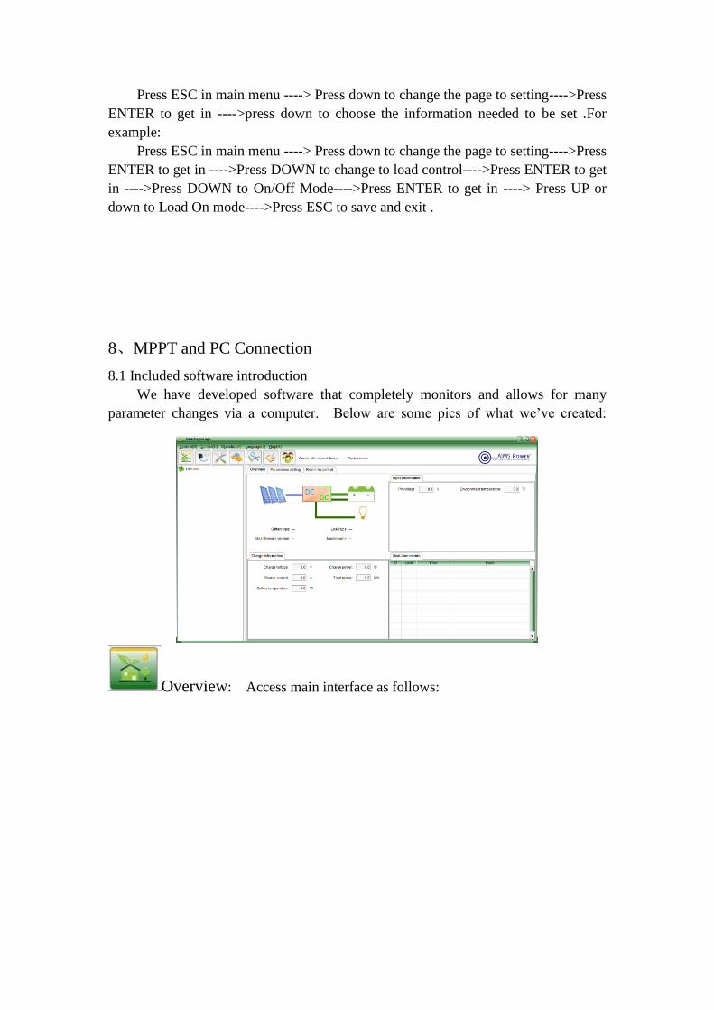
8.1 Included software introduction
We have developed software that completely monitors and allows for many
parameter changes via a computer. Below are some pics of what we’ve created:
Overview: Access main interface as follows:
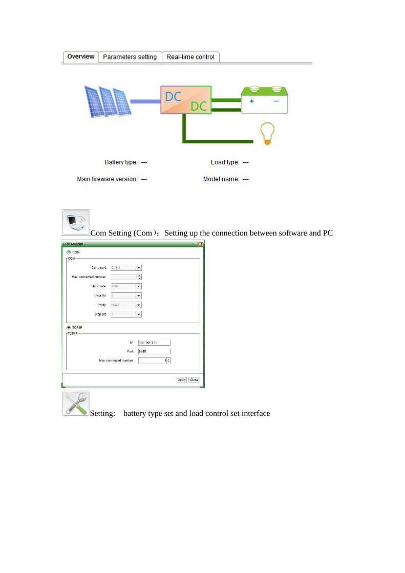
Com Setting (Com):Setting up the connection between software and PC
Setting: battery type set and load control set interface

Data:MPPT working status
Event Log :MPPT working status per day
Login :Some parameters set need administrator’s password.
8.2 Connecting of MPPT and software.
Could connect trough RS 232 (COM) or (TCP/IP)
8.2.1 Connect through RS232 (COM)
1)if PC has RS232 connector, check the following picture
Step 1: Please install software. For details please check install steps.
Step 2: Once software is installed and controller is connected properly, allow
controller to turn to on state (connected controller to battery will automatically start)
Step 3: Connected PC and controller with RS232 and PC will notice the
communication, at this time the PC will chose COM1:
Step 4: Open the software as administrator (WIN 7 of 8), then press to choose
COM communication and enter. It will automatically connect:
Step 5: The software is now ready to be used.
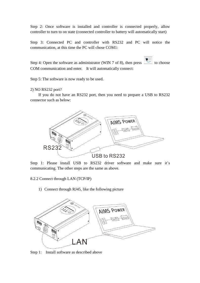
2) NO RS232 port?
If you do not have an RS232 port, then you need to prepare a USB to RS232
connector such as below:
Step 1: Please install USB to RS232 driver software and make sure it’s
communicating. The other steps are the same as above.
8.2.2 Connect through LAN (TCP/IP)
1) Connect through RJ45, like the following picture
Step 1: Install software as described above
Step 2: Install and ensure controller is properly wired. Allow it to turn on. This
happens automatically when battery is properly connected.
Step 3: Connect PC and controller using RJ45.
Step 4:
First method: Based on PC GATED ADDRESS and IP ADDRESS set the
controller’s PC GATED ADDRESS and IP ADDRESS. But please note the last
number of IP address must be different. Ex: PC’s PC GATED ADDRESS is
192.168.1.1, IP ADDRESS is 192.168.1.10, then the controller GATED ADDRESS is
192.168.1.1, IP ADDRESS is 192.168.1.8: Make sure controller and PC are in the
same LAN.
Second method: Based on PC GATED ADDRESS and IP ADDRESS set the
controller’s PC GATED ADDRESS and IP ADDRESS. But please note the last
number of IP address should be kept different. Ex: Controller’s GATED ADDRESS
is 192.168.1.1, IP ADDRESS is 192.168.1.10, then the PC’s GATED ADDRESS is
192.168.1.1, IP ADDRESS is 192.168.1.8: Make sure controller and PC are in the
same LAN.
Step 5: Open the software as the administrator (WIN 7 or 8). Then press to
choose TCP/IP communication and fill IP address and port number, enter; It will
automatic connect in 10s: If they do not connect, make sure controller and PC in the
same LAN and restart controller .
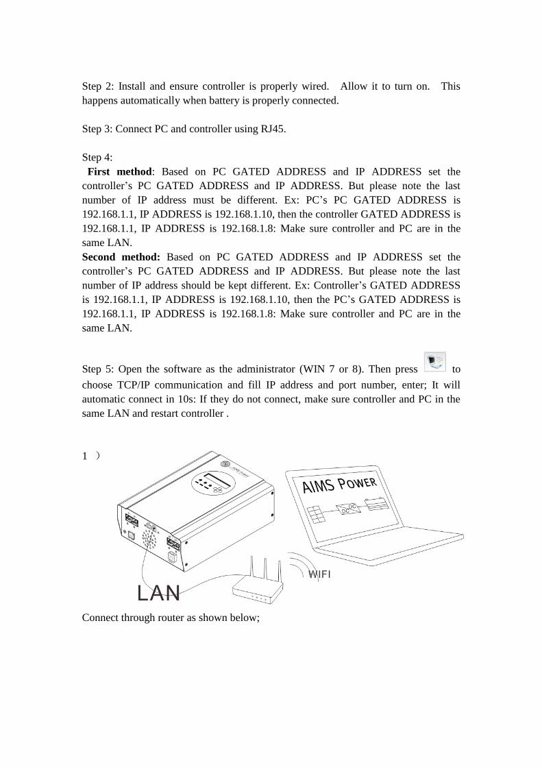
1 )
Connect through router as shown below;
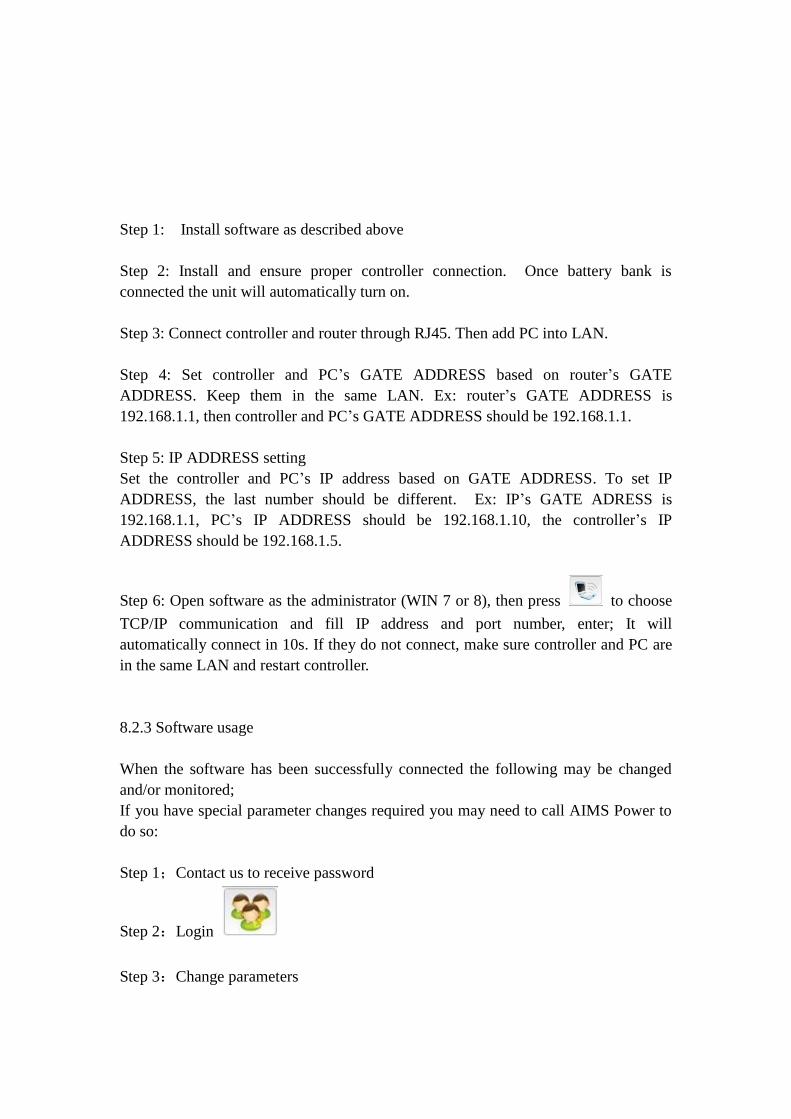
Step 1: Install software as described above
Step 2: Install and ensure proper controller connection. Once battery bank is
connected the unit will automatically turn on.
Step 3: Connect controller and router through RJ45. Then add PC into LAN.
Step 4: Set controller and PC’s GATE ADDRESS based on router’s GATE
ADDRESS. Keep them in the same LAN. Ex: router’s GATE ADDRESS is
192.168.1.1, then controller and PC’s GATE ADDRESS should be 192.168.1.1.
Step 5: IP ADDRESS setting
Set the controller and PC’s IP address based on GATE ADDRESS. To set IP
ADDRESS, the last number should be different. Ex: IP’s GATE ADRESS is
192.168.1.1, PC’s IP ADDRESS should be 192.168.1.10, the controller’s IP
ADDRESS should be 192.168.1.5.
Step 6: Open software as the administrator (WIN 7 or 8), then press to choose
TCP/IP communication and fill IP address and port number, enter; It will
automatically connect in 10s. If they do not connect, make sure controller and PC are
in the same LAN and restart controller.
8.2.3 Software usage
When the software has been successfully connected the following may be changed
and/or monitored;
If you have special parameter changes required you may need to call AIMS Power to
do so:
Step 1;Contact us to receive password
Step 2:Login
Step 3:Change parameters

9、Parameters
Model: SCC60MPPT 60A
Charge Mode Maximum Power Point Tracking
Method 3 stages: fast charge(MPPT),constant voltage, floating charge
System Type DC12V/24V/48V Automatic recognition
System Voltage
12V system DC9V~DC15V
24V system DC18V~DC30V
48Vsystem DC36V~DC60V
Soft Start Time 12V/24V/48Vsyste
m ≤10S
Dynamic Response
Recovery Time
12V/24V/48Vsyste
m 500us
Conversion
Efficiency
12V/24V/48Vsyste
m ≥96.5%,≤99%
PV Modules
Utilization Rate
12V/24V/48Vsyste
m ≥99%
Input Characteristics
MPPT Working
Voltage and Range
12V system DC18V~DC150V
24V system DC34~DC150V
48V system DC65~DC150V
Low Voltage Input
Protection Point
12V system DC16V
24V system DC30V
48V system DC60V
Low Voltage Input
Recovery Point
12V system DC22V
24V system DC34V
48V system DC65V
Max DC Voltage 12V/24V/48V
system DC160V
Input Overvoltage
Protection Point
12V/24V/48V
system DC150
Input Overvoltage
Recovery Point
12V/24V/48V
system DC145V
Max. PV Power
12V system 900W
24V system 1700W
48V system 3400W
Output Characteristics
Selectable Battery
Types (Default type
is GEL battery)
12V/24V/48Vsyste
m
Sealed lead acid, vented, Gel, NiCd battery
(Other types of the batteries also can be defined)
Constant Voltage 12V/24V/48V Please check the charge voltage according to the battery
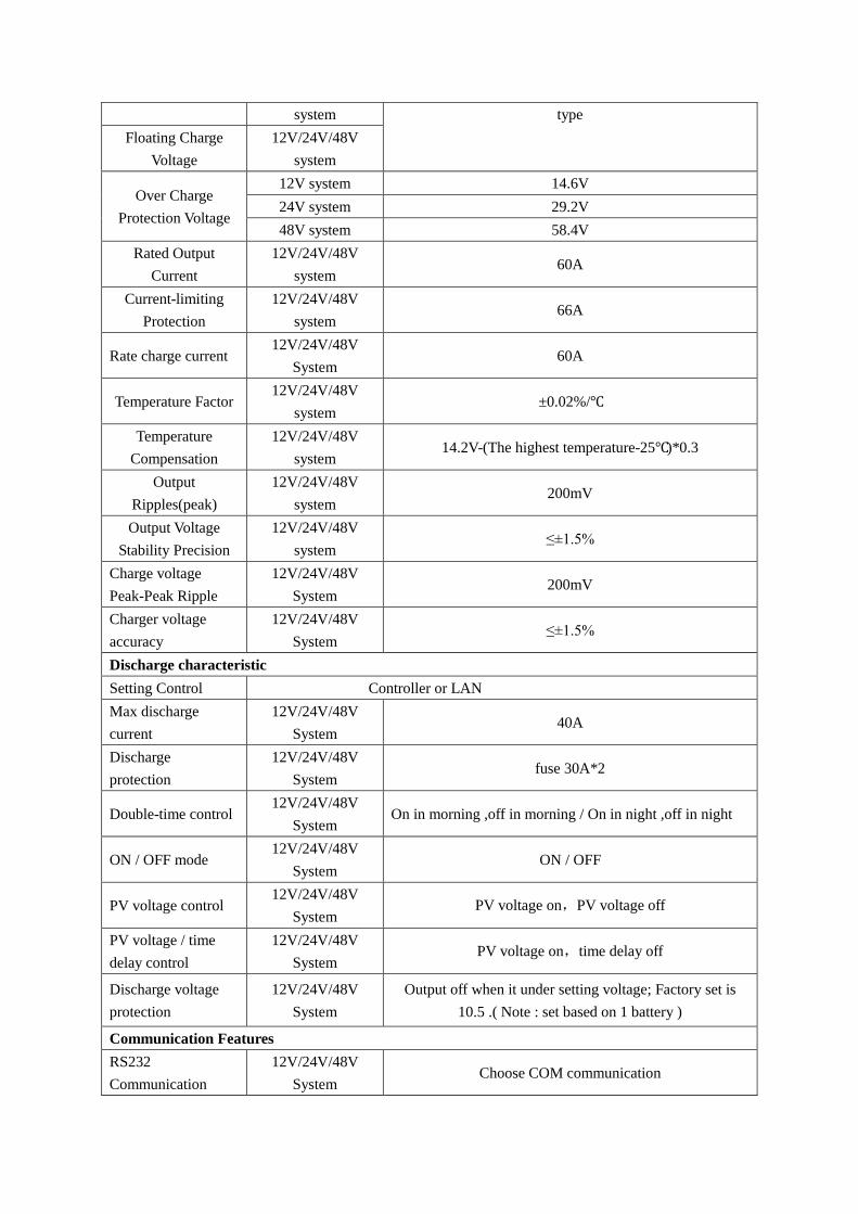
system type
Floating Charge
Voltage
12V/24V/48V
system
Over Charge
Protection Voltage
12V system 14.6V
24V system 29.2V
48V system 58.4V
Rated Output
Current
12V/24V/48V
system 60A
Current-limiting
Protection
12V/24V/48V
system 66A
Rate charge current 12V/24V/48V
System 60A
Temperature Factor 12V/24V/48V
system ±0.02%/℃
Temperature
Compensation
12V/24V/48V
system 14.2V-(The highest temperature-25℃)*0.3
Output
Ripples(peak)
12V/24V/48V
system 200mV
Output Voltage
Stability Precision
12V/24V/48V
system ≤±1.5%
Charge voltage
Peak-Peak Ripple
12V/24V/48V
System 200mV
Charger voltage
accuracy
12V/24V/48V
System ≤±1.5%
Discharge characteristic
Setting Control Controller or LAN
Max discharge
current
12V/24V/48V
System 40A
Discharge
protection
12V/24V/48V
System fuse 30A*2
Double-time control 12V/24V/48V
System On in morning ,off in morning / On in night ,off in night
ON / OFF mode 12V/24V/48V
System ON / OFF
PV voltage control 12V/24V/48V
System PV voltage on,PV voltage off
PV voltage / time
delay control
12V/24V/48V
System PV voltage on,time delay off
Discharge voltage
protection
12V/24V/48V
System
Output off when it under setting voltage; Factory set is
10.5 .( Note : set based on 1 battery )
Communication Features
RS232
Communication
12V/24V/48V
System Choose COM communication

LAN
Communication
12V/24V/48V
System
Set IP and Gate address for controller and software; Then
choose TCP communication
Protection
Input Low Voltage Protection Check the input characteristics
Input Overvoltage Protection Check the input characteristics
Input Polarity Reversal Protection yes
Output Overvoltage Protection Check the output characteristics
Output Polarity Reversal Protection yes
Short-circuit Protection Recover after eliminating the Short-circuit fault, no
problem for long term Short-circuit
Temperature Protection 95℃
Temperature protection Above 85℃,decrease the output power, decrease 3A per
degree.
Other Parameters
Noise ≤40dB
Thermal methods
Forced air cooling, fan speed rate regulated by
temperature, when inner temperature is too low, fan runs
slowly or stops; when controller stops working, fan also
stops running
Components
World brand raw materials. Compliance with EU
standards. All rated temperature of electrolytic capacitors
not less than 105℃
Smell No peculiar smell or toxic substances
Environment Protection Meet the 2002/95/EC, no cadmium hydride and fluoride
Physical
Measurement DxWxH (mm) 270*185*90
N.G(kg) 3
G.N(kg) 3.6
Color Black
Safety CE, RoHS, PSE,FCC
EMC EN61000
Type of Mechanical Protection IP21
Environment
Humidity 0~90%RH ( no condense)
Altitude 0~3000m or about 10,000ft
Operating Temperature -20℃ ~ +40℃
Storage Temperature -40℃ ~ +75℃
Atmospheric Pressure 70~106kPa

10. Maintenance and Cleaning
10.1 Replacing the Thermal Fuses
Using incorrect thermal fuses may irreparably damage the solar charge controller.
• Only use the thermal fuses included in the scope of delivery
1. Open the solar charge controller as described in section "Opening the solar charge
controller"
2. Remove the broken thermal fuses from the sockets (A and B).
3. Insert new thermal fuses (included in the scope of delivery).
4. Close the solar charge controller as described in section "Closing the solar charge
controller".
5. Remember always connect the batteries before the solar panels or you will
permanently damage the controller.
Note: To clean simply wipe the outside with a lightly dampened cloth. If unit has
been opened use an air spray such as a keyboard cleaner to blow out the internal
dust that may accumulate inside the controller.

Location of Thermal Fuses
10.2 Cleaning the Cooling Fan
Clean the Fan air vents and internal cooling fan regularly by using a dry or slightly
damp cloth to wipe.
Attention:
• Liquid detergent or corrosive solvent cleaning is forbidden.
• Liquid is not allowed in the device.
• clear the air vent passage.
•Carefully remove dirt with a suitable soft brush if deemed necessary.
11. Storage and waste disposal.
10.1 Store the charge controller in a dry place with ambient temperatures between
-40 °C and +75 °C.
10.2 Disposal
Dispose of the solar charge controller at the end of its service life in accordance with
the disposal regulations for electronic waste at the installation site at that time.
12. Warranty and Repair
12.1 Repair
When the controller mal-functions, please check the following questions and contact
our customer service representative if you need assistance.
11.1.1 Controller failure mode:
Please check the fault tips in the failure mode, and then proceed to the appropriate
troubleshooting;
11.1.2 When the controller does not start properly:
1. Check to ensure polarity between panels and controller are correct
2. Check Battery Connection
3. Check Battery
4. Check circuit breaker
5. Check internal fuse
If the problem persists, please contact customer service.
Please provide the following information:Equipment information: Model, Order No.,
serial-number (Stickers on the rear plate); Detailed description of the problem
(Type of system, occasionally/frequent problems, indicator light, data display, and so
on).
12.2 Warranty
AIMS Power® PRODUCT WARRANTY POLICY
AIMS Power® will either repair, replace, or refund at its option, defective AIMS Power® branded
products according to the specified warranty periods below:
All AIMS Power® branded products—1 year warranty unless noted differently on
product. Warranty is void if product has been altered, scratched, damaged or tampered
with in any way.
TO RETURN MERCHANDISE:
OBTAIN A RMA #
1. All returns must have a RMA number for processing.
2. Packages without a RMA number on the outside of the package will not be accepted.
RETURN PACKAGING – Repack the product in its original packaging, along with all manuals
and related materials. Place the packaged product in a protective outer box. The RMA number
must be clearly marked on the outside box / package. Please Note: We must receive all
original products in order to process your return or exchange. AIMS Power® is not
responsible for products that are damaged due to poor packaging or lost shipments.
Remember to keep your Tracking Number.
RETURN SHIPPING CHARGES – The customer is responsible for shipping charges on
returned products; AIMS® will send replacements via Ground freight at no charge. We
recommend shipping via ground.
RETURN SHIPPING METHOD – AIMS Power® strongly recommends you fully insure your
return shipment in case it is lost or damaged in transit. We also recommend you use a carrier that
can provide you with proof of delivery for your protection. Remember to keep your Tracking
Number.
PRODUCT DAMAGED IN TRANSIT – If your product arrived DAMAGED in transit, it is
best to REFUSE it back to the carrier attempting delivery. Please inform AIMS Power® of the
refusal. If you accept the package, make sure it is noted on the carrier’s delivery record in order
for AIMS Power® to file a damage claim. Save the merchandise and the original box and
packing it arrived in; notify AIMS Power® immediately to arrange for a carrier inspection and
pick up of the damaged merchandise.
RETURNED PRODUCT CONDITION:
LIKE NEW CONDITION – All returned products must be returned 100% complete, including
all of its components, all original boxes and packing materials, manuals, blank warranty cards and
other accessories provided by the manufacturer.
INCOMPLETE, SCRATCHED or DAMAGED CONDITION – AIMSPower® reserves the
right to refuse crediting the customer’s account and the product will be returned to the customer.
DEFECTIVE PRODUCT – After 30 days, defective product may be returned for repair or
exchange only, at AIMS®’s option.
Upon receipt of an RMA number, ship returns to the following address:
AIMSPower®
Attn: Returns Dept.
9736 South Virginia Street, Suite A
Reno, NV 89511
(775)359-6703
Any legal action to enforce any of the terms of this or any other agreement shall be governed by
the laws of the State of Nevada and may be instituted in state or federal court.
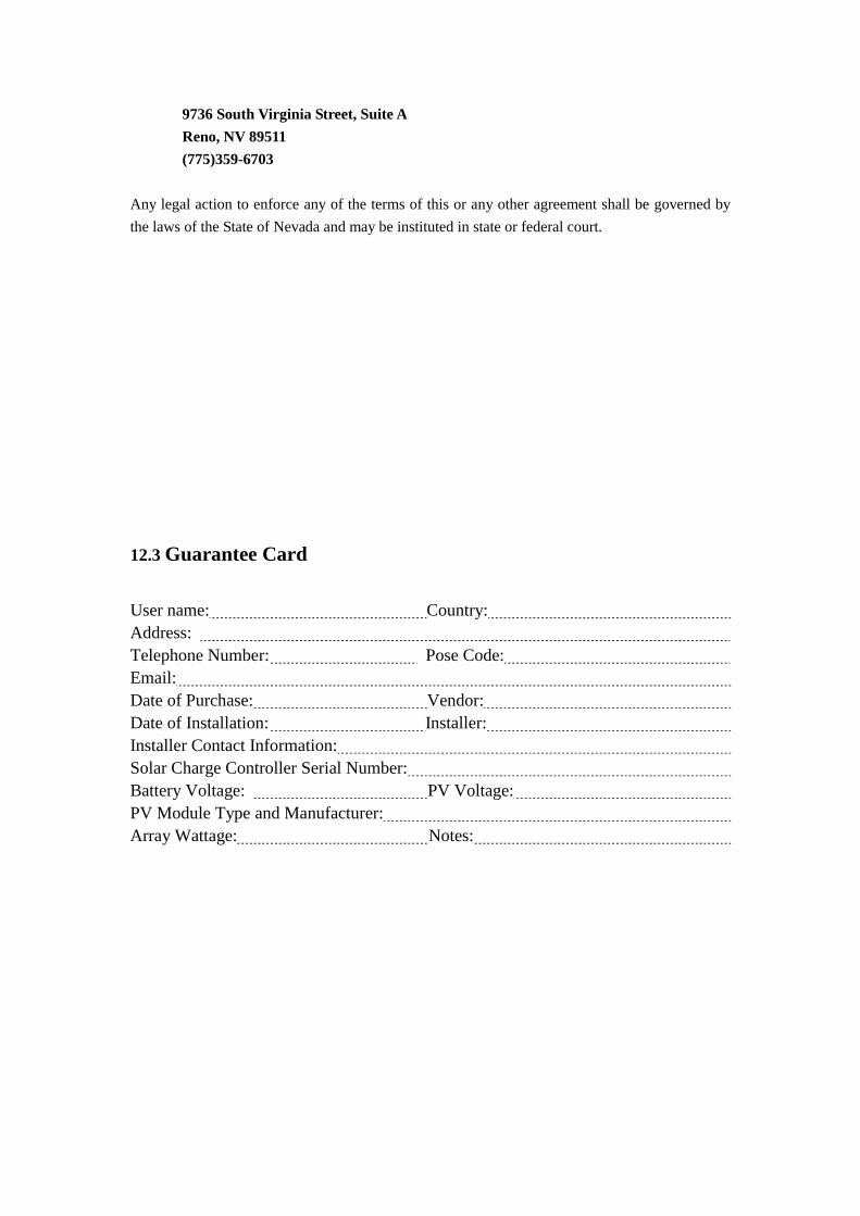
12.3 Guarantee Card
User name: Country:
Address:
Telephone Number: Pose Code:
Email:
Date of Purchase: Vendor:
Date of Installation: Installer:
Installer Contact Information:
Solar Charge Controller Serial Number:
Battery Voltage: PV Voltage:
PV Module Type and Manufacturer:
Array Wattage: Notes: