ai/ml assisted li-fi communication systems for the future
TRANSCRIPT

NATIONAL AND KAPODISTRIAN UNIVERSITY OF ATHENS
SCHOOL OF SCIENCE DEPARTMENT OF INFORMATICS AND TELECOMMUNICATION
MSc THESIS
AI/ML assisted Li-Fi communication systems for the future 6G communication systems
Khojiakbar B. Botirov Sanjar
Supervisors: Dimitris Syvridis, professor Panagiotis Stamapoulos, professor
ATHENS
September 2021

MSc THESIS
AI/ML assisted Li-Fi communication systems for the future 6G communication systems
Khojiakbar B. Botirov Sanjar
S.N.: 1200005
SUPERVISORS: Dimitris Syvridis, professor Panagiotis Stamapoulos, professor

ABSTRACT
Information and communication technologies are developing rapidly, and tremendous growth along with advancements was observed over the last few decades. Requirements for bandwidth and capacity of current networks are overgrowing due to the increase in the use of high-speed Internet, video conferencing, streaming, Internet of things, etc. An ever-growing demand for increasing data volumes and multimedia services has led to an overload in the traditional radio frequency (RF) spectrum is used, and there is a need for transition from RF carrier to optical media. In this work, novel Deep Neural Network (DNN) was proposed to mitigate nonlinearities caused by Perovskite material-based components of Li-Fi communication system, and measurement of Perovskite Photodiodes (PePD) the Optical Communications Laboratory in the National and Kapodistrian University of Athens. Due to the analysis of the PePDs bandwidth measurement, the highest cut-off frequency was measured 36,25kHz at 635nm wavelength. The proposed DNN showed promising results in comparison with Support Vector Machines (SVM) model, both models were trained on the dataset generated by OFDM based - Li-Fi systems. This technique successfully mitigates the nonlinearity of the PePD and the interference generated by the multipath channel. The simulation results reveal that the proposed scheme outperforms conventional techniques in terms of BER performance demonstrating the potential and validity of DL in the Li-Fi system.
SUBJECT AREA: Wireless Optical Networks, Deep Learning
KEYWORDS: Li-Fi, PePD, PeLED, DNN

I dedicate my dissertation work to my family. To my parents, Sanjar, and
Nigora. Their words of encouragement and support pushed me to do
better and be the person I am today.

ACKNOWLEDGMENTS
I would like to thank my supervisor Prof. Dimitris Syvridis and Panagiotis Stamapoulos for great help, exceptional motivation, and valuable advice given during our hard work.
I would like to thank my co-supervisors Dr. Nikolaos Raptis and Stylianos Kazazis for creative ideas, incredible driving force, professional advice, great help.
I would like to thank my colleague Afnan Amayreh for a valuable contribution to the work, many hours of work together and a great experiment.
This Master Thesis has been accomplished in the framework of the European Funded Project: SMART Telecom and Sensing Networks (SMARTNET) - Erasmus+ Programme Key Action 1: Erasmus Mundus Joint Master Degrees – Ref. Number 2017 – 2734/001 – 001, Project number - 586686-EPP-1-2017-1-UK-EPPKA1-JMD-MOB, coordinated by Aston University, and with the participation of Télécom SudParis, member of IP Paris and National and Kapodistrian University of Athens.

CONTENTS
1. INTRODUCTION………………………………………………..………………………. 10
1.1 From VLC to Li-Fi……………………………………………………………………..…………………. 10
1.1.1 Main benefits of Li-Fi…………………………………………………………………………………. 11
1.1.2 The Li-Fi Vendors Ecosystem………………………………………………………………………. 12
1.1.3 Market Feedback and Main Li-Fi Use Cases……………………………………………………. 13
1.2 Standardization and ecosystem development…………………………………..…………………. 13
1.2.1 Early standards…………………………………………………………………….…………………. 13
1.2.2 IEEE 802.15.13 for Industrial Applications……………………………………..…………………. 14
1.2.3 IEEE 802.11bb for Mass-Markets……………………………………………….…………………. 14
1.2.4 ITU G.vlc………………………………………………………………………………………………. 15
1.2.5 The Light Communication Alliance…………………………………………………………………. 15
1.3 Modulation techniques in Li-Fi …………………………………………………….…………………. 16
1.4 Perovskite based diodes in Li-Fi…………………………………………………...…………………. 17
1.4.1 Perovskite based LED…………………………………………………………….…………………. 18
1.4.2 High-sensitive perovskite photodetectors…………………………………….……………………. 18
1.5 Machine Learning in VLC………………………………………………………………………………. 19
1.5.1 The Architecture of ML Enhanced VLC System……………………………….…………………. 19
2. METHODS………………………………………………………………………………..…………………. 21
2.1 Perovskite diodes……………………………………………………………………..…………………. 21
2.1.1 Perovskite LED…………………………………………………………………….…………………. 21
2.1.2 Perovskite PD……………………………………………………………………...…………………. 24
2.1.3 PePD bandwidth measurements………………………………………………...…………………. 25
2.2 Channel model design………………………………………………………………..………………… 31
2.2.1 The properties of indoor environment………………………………………….…………………... 33
2.3 The modulation technique used in the Li-Fi system………………………………………………. 33
2.4 Applying Deep Learning to reduce nonlinearities at the receiver………………………………. 35
2.4.1 The dataset preparation…………………………………………………………..…………………. 36

2.4.2 DNN Training …………………………………………………………………………………………. 37
3. RESULTS AND DISSCUSSION……………………………………………………….…………………. 38
3.1 PePD’s measurement results………………………………………………………..………………… 38
3.2 The DNN influence evaluation ………………………………………………………..……………… 41
4. CONCLUSION………………………………………………………………………………………………. 44
ABBREVIATIONS – ACRONYMS………………………………………………………..…………………. 46
ANNEX Ι……………………………………………………………………………………..………………….. 48
ANNEX II………………………………………………………………………………………………………... 53
REFERENCES…………………………………………………………………………………………………. 54

LIST OF FIGURES
Figure 1: The Li-FiMAX AP and dongles............................................................. 12
Figure 2: A machine learning enhanced VLC …...…………………………………. 19
Figure 3: Schematic illustration of PeLEDs. ……………………………………….. 22
Figure 4: Characterization of PeLEDs………………………………………………. 23
Figure 5: PePD bandwidth measurements design………………………………… 26
Figure 6: EQE versus wavelength relationship of PePDs…………………………. 29
Figure 7: Electrical power response vs Frequency of PePD3 small at 515nm….. 29
Figure 8: Rise time measurement of pulsed signal of PePD3 small at 515nm…... 30
Figure 9: FFT and Electrical power response of PePD3 small at 515nm………… 31
Figure 10: Baseband equivalent model of a VLC employing IM/DD……………….. 31
Figure 11: LoS and first-order NLoS paths of the Li-Fi channel ………………….... 32
Figure 12: Visualization of the room design………………………………………….. 33
Figure 13: Block diagram of Flip-OFDM……………………………………………… 34
Figure 14: Flip-OFDM unipolar frame…………………………………….................. 34
Figure 15: MLP consistion of 2 hidden layers………………………………………... 35
Figure 16: BER and Distance between PeLED and PePD…………………………. 41
Figure 17: The 5-Fold cross validation of DNN………………………………………. 42
Figure 18: Constellation of received 16-QAM signal before and after DNN………. 42
Figure 19: BER vs Number of PeLEDs per array, b. BER vs SNR…………………. 43
Figure 20: Values of large PePDs bandwidth thought different methods………… 53
Figure 21: Values of small PePDs bandwidth thought different methods………... 53
Figure 22: PePD4 small Dark Current vs Voltage ………………………………… 53

LIST OF TABLES
Table 1: Feature comparison of the main Li-Fi standards………………………… 14
Table 2: Parameters of PeLED ……………………………………………………… 23
Table 3: Characteristics of OSRAM PLT5 510…………………………………….. 25
Table 4: Characteristics of ROHM RLD64NPC5…………………………………... 25
Table 5: Specifications of reference PD PDA25K-EC…………………………….. 26
Table 6: Reference commercial PD measurement results……………………….. 27
Table 7: Characteristics of PePDs…………………………………………………... 28
Table 8: PeLED arrays location……………………………………………………… 33
Table 9: Topology of DNN……………………………………………………………. 37
Table 10: PePDs bandwidth estimation via peak voltage measurement…………. 39
Table 11: PePDs bandwidth estimation via rise time measurement ……………… 39
Table 12: PePDs bandwidth estimation via FFT measurement…………………… 40
AI/ML assisted Li-Fi communication system for the future 6G communication systems
Kh. Botirov 10
1. INTRODUCTION
Due to the increasing demand for wireless data communication, the available radio spectrum below 10 GHz (cmwave communication) has become insufficient. The wireless communication industry has addressed to this obstacle by investigating radio frequencies greater than 10 GHz (mm-wave communication). The higher the frequency, the greater the path loss, according to the Friis free space equation (L f2). Additionally, at higher frequencies, obstructions and shadowing in terrestrial transmission are more difficult to overcome. As a result, systems must be built to maximize the likelihood of line-of-sight (LoS), which is generally accomplished by the use of beamforming methods and the use of extremely tiny cells (approximately 50 m in radius). From a system capacity standpoint, the requirement for tiny cells is irrelevant. This is because shrinking cell sizes has undoubtedly been the primary factor in improving system performance in modern cellular communications. Contrary to popular belief, this means that using higher frequencies for terrestrial communication has become a viable alternative. However, one drawback is that the task of sustaining ever-smaller cells becomes considerable. Providing advanced backhaul infrastructure is one such example. Light-fidelity (Li-Fi) [is a continuation of the electromagnetic spectrum's movement toward higher frequencies. Li-Fi is a kind of nm-wave communication. Li-Fi employs light emitting diodes (LEDs) for
high-speed wireless communication, and rates of over 3 Gb/s have been shown utilizing
optimized direct current optical orthogonal frequency division multiplexing (DCO-OFDM)
modulation on a single micro-light emitting diode (LED) [3]. Given the increasing use of LED
lighting in homes, workplaces, and streetlights due to their energy efficiency, Li-Fi cellular
deployment has the added benefit of being able to leverage existing lighting infrastructures.
Additionally, compared to mm-wave communication, cell sizes can be decreased further,
resulting in the notion of Li-Fi attocells. Li-Fi attocells act as an extra network layer within
existing heterogeneous wireless networks, causing no interference with or adding to their
radio frequency (RF) equivalents, such as femtocell networks. A Li-Fi attocell network makes
advantage of the lighting system to enable fully networked wireless connection (multiuser
access and handover).
1.1 From VLC to Li-Fi
VLC employments LEDs to transmit information wirelessly by utilizing intensity modulation
(IM). At the photodiode, the signal is recognized by a photodiode (PD) and
by utilizing the principle of direct detection (DD). VLC has been conceived as a point-to-
point information communication technique – basically as a cable substitution. This
has driven to early VLC standardization exercises as portion of IEEE 802.15.7 [6]. This
standard, in any case, is as of now being revised to incorporate Li-Fi. Li-Fi
in differentiate portrays a total wireless networking framework. This incorporates bi-
directional multiuser communication, i.e. point-to-multipoint and multipoint-to-point
communication. Li-Fi also includes various access points to form a remote system of
extremely small optical cells with sequential handoff. This implies that Li-
Fi empowers full client portability, and so shapes a modern layer inside the existing
heterogeneous wireless systems. The fact that LEDs are characteristic beamformers
enables neighborhood control of Li-Fi signals, and because of the blockage of the signals by

AI/ML assisted Li-Fi communication system for the future 6G communication systems
Kh. Botirov 11
opaque walls, co-channel interference (CCI) can effectively be overseen and physical layer
security can be enhanced. At the core are novel devices such as perovskite based diodes,
gallium nitride (GaN) micro-LEDs and single photon avalanche diodes. These are inserted
in optical front-ends and subsystems which incorporate versatile optics additionally the
analogue circuitry to drive the LEDs and shape the signals gotten from the PDs at the
recipients. In arrange to accurately demonstrate link margins, establish the coherence
transfer speed of the channel and correctly model CCI, exact channel models are required
which take the spectral composition of the flag into consideration [7]. Connect level
algorithms are required to ideally shape the signals to maximize the information throughput.
In this setting, due to the inspiration of the power signals in IM, an unused hypothetical
system is needed to build up the channel capacity since the conventional Shannon
framework isn't entirely pertinent [8]. New medium access control (MAC) protocols that take
into consideration the unique features of the Li-Fi physical layer are necessary to enable
multiuser access. To maintain fairness and good overall system performance, interference
mitigation methods are also required. Finally, the optical attocell network should be
incorporated into software-defined networks that are regulated by the separation of the
network components. This necessitates the creation of new Li-Fi agents. There has been a
lot of study into the inner two layers that characterize VLC, but there has been relatively little
research into the remaining areas, such as channel modeling, where there has been a
heightened interest recently.
1.1.1 Main benefits of Li-Fi
Li-Fi's indisputable benefits stem from the characteristics of light. As previously stated, it
provides a highly broad and uncontrolled spectrum that may be used to produce
extraordinarily high data speeds, particularly when data is sent over parallel wavelengths
[32]. Simultaneously, Li-Fi offers more security than RF technologies since light beams
cannot pass through barriers and may be easily bent by optical devices, reducing the danger
of accidental eavesdropping. Additionally, Li-Fi may benefit from great spectrum efficiency
by pushing the boundaries of spatial reuse. As with other wireless technologies, Li-Fi is
based on cells formed by geographically scattered access points (AP) that provide
continuous connectivity to any suitable mobile user equipment (UE). An AP's coverage is
constrained by the light source's characteristics, which are governed by eye safety or lighting
standards. As a result, Li-Fi cells often have diameters of a few meters, far smaller than
conventional RF cells. These benefits, combined with the fact that light does not interfere
with radio frequency (RF), make Li-Fi an intriguing solution for complementing and offloading
the RF spectrum, as well as providing wireless connectivity in areas where RF is restricted
due to electromagnetic interference or health concerns. For instance, France's 2015 "Loi
Abeille" forbids the use of WiFi in sections of public businesses dedicated to the welcome,
relaxation, and activities of children under the age of three [34]. Finally, one of the most
recent significant concepts in Li-Fi is to leverage existing LED lighting infrastructure to offer
network access, as more than 70% of traffic happens inside [33]. This manner, the rising
demand for connection can be met with little additional energy consumption and without the
need for new, dedicated infrastructure, making Li-Fi a ‘green' technology compatible with 6G
aspirations.

AI/ML assisted Li-Fi communication system for the future 6G communication systems
Kh. Botirov 12
1.1.2 The Li-Fi Vendors Ecosystem
In the 2010s, numerous organizations in Europe began commercializing Li-Fi technologies.
Oledcomm was founded in 2012 as a spin-off from the University Paris-Saclay, following
initial research on automotive VLC at the Laboratoire d'Ingénierie des Systèmes de
Versailles. Following the development of the VLC and OCC product lines, Oledcomm
concentrated its efforts on the creation of Li-Fi devices, which is currently its primary
emphasis. In 2017, MyLi-Fi introduced the MyLi-Fi lamp, which was meant primarily as a
remotely operated light treatment lamp but also included a 10 Mbps Li-Fi network connection.
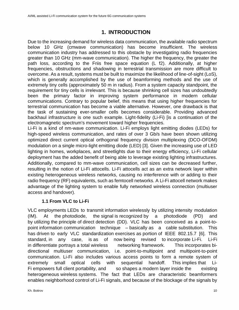
Then, in 2019, the Li-FiMAX solution for indoor networking was released, as seen in Figure1.
Other European organizations, such as the businesses pureLi-Fi and Signify, as well as the
Fraunhofer research institution, are currently offering Li-Fi solutions. pureLi-Fi was formed in
2012 as a spin-off from the University of Edinburgh and debuted the Li-Fi-XC product for
indoor networking with Li-Fi-integrated lighting in 2017 in collaboration with the lighting firm
Lucibel.
Figure 1. The Li-FiMAX AP and dongles
Then, in 2019, it unveiled the Gigabit Li-Fi component, a thin, light antenna that can be
installed directly into mobile devices. On the other hand, Signify was formerly the lighting
business section of Royal Philips, which bought the start-ups Luciom and subsequently
Firefly in order to launch its TruLi-Fi range of devices in 2019. Finally, the Fraunhofer institute
has a long history of research on OWC, which resulted in the Heinrich Hertz Institute (HHI)
developing the Gigabit VLC module and the Institute for Photonic Microsystems developing
the Li-Fi Hotspot (IPMS). Outside of Europe, Li-Fi has attracted industrial attention, with
suppliers such as VLNComm in the United States and Velmeni in India. Simultaneously,
numerous firms in the lighting and telecommunications industries, such as Nokia, Orange,
and Ledvance, are actively monitoring the Li-Fi market's growth, despite the fact that they
are not direct sellers.
AI/ML assisted Li-Fi communication system for the future 6G communication systems
Kh. Botirov 13
1.1.3 Market Feedback and Main Li-Fi Use Cases
In the 2010s, numerous organizations in Europe began commercializing Li-Fi technologies.
Oledcomm was founded in 2012 as a spin-off from the University Paris-Saclay, following
initial research on automotive VLC at the Laboratoire d'Ingénierie des Systèmes de
Versailles. Following the development of the VLC and OCC product lines, Oledcomm
concentrated its efforts on the creation of Li-Fi devices, which is currently its primary
emphasis. In 2017, MyLi-Fi introduced the MyLi-Fi lamp, which was meant primarily as a
remotely operated light treatment lamp but also included a 10 Mbps Li-Fi network connection.
Then, in 2019, the Li-FiMAX solution for indoor networking was released, as seen in Figure
1 and explained in Section II. Other European organizations, such as the businesses pureLi-
Fi and Signify, as well as the Fraunhofer research institution, are currently offering Li-Fi
solutions. pureLi-Fi was formed in 2012 as a spin-off from the University of Edinburgh and
debuted the Li-Fi-XC product for indoor networking with Li-Fi-integrated lighting in 2017 in
collaboration with the lighting firm Lucibel.
Then, in 2019, it unveiled the Gigabit Li-Fi component, a thin, light antenna that can be
installed directly into mobile devices. On the other hand, Signify was formerly the lighting
business section of Royal Philips, which bought the start-ups Luciom and subsequently
Firefly in order to launch its TruLi-Fi range of devices in 2019. Finally, the Fraunhofer institute
has a long history of research on OWC, which resulted in the Heinrich Hertz Institute (HHI)
developing the Gigabit VLC module and the Institute for Photonic Microsystems developing
the Li-Fi Hotspot (IPMS). Outside of Europe, Li-Fi has attracted industrial attention, with
suppliers such as VLNComm in the United States and Velmeni in India. Simultaneously, and
as discussed in Section IVE, numerous firms in the lighting and telecommunications
industries, such as Nokia, Orange, and Ledvance, are actively monitoring the Li-Fi market's
growth, despite the fact that they are not direct sellers.
1.2 Standardization and ecosystem development
The widespread adoption of a technology like Li-Fi is predicated on two key tenets. On the
one hand, there exist standards, which are a necessary condition for widespread adoption
of Li-Fi systems. On the other hand, Li-Fi manufacturers alone cannot expand the market;
they must be incorporated into a wider ecosystem comprised of several companies in diverse
areas. Sections below provide an overview of the different existing Li-Fi standards.
1.2.1 Early standards
After the Japan Electronics and Information Technology Industries Association (JEITA)
published two initial VLC standards in 2007 – the JEITA CP-1221 and JEITA CP-1222 –
standardization efforts were concentrated in 2009 within the IEEE, more precisely within its
802.15 working group, initially through task group (TG) 7. Thus, in 2011, an IEEE 802.15.7-
2011 standard inspired by ZigBee is issued, increasing VLC's exposure. However, this
standard is rarely maintained, which is why the TG7 began a redesign in 2015 that would
result in a new mount primarily dedicated to OCC in 2018. Meanwhile, standardization efforts
on Li-Fi have been centered in the IEEE 802.15.13 group from 2017 and in parallel with the
IEEE 802.11bb group since 2018.

AI/ML assisted Li-Fi communication system for the future 6G communication systems
Kh. Botirov 14
1.2.2 IEEE 802.15.13 for Industrial Applications
TG13 was formed after it became obvious that IEEE 802.15.7 could not adequately address
OCC and Li-Fi. Its objective is to provide an OWC standard that enables data transfer speeds
of up to 10 Gbps over a distance of 200 meters in point-to-point and point-to-multipoint
configurations with wavelengths ranging from 10,000 to 190 nm. The first critical point is the
definition of a primary physical (PHY) layer based on DC-biased optical orthogonal frequency
division multiplexing (DCO-OFDM) with adaptive bit-power-loading, a technique derived from
G.hn and designed to optimize link performance in the presence of channel variations.
Additionally, a low-power PHY layer based on pulsed modulations is specified for the most
resource-intensive use cases.
The other critical aspect is the inclusion of a coordinated topology at the medium access
control (MAC) level, with a 'master coordinator' capable of managing multiple 'coordinators'
acting as APs to the UEs. This architecture, dubbed dispersed multiple input multiple output
(MIMO), is notable for its ability to enable extremely rapid handover, making it ideal for highly
mobile applications like as industrial robots. A second, more conventional MAC is also
established to accommodate corporate applications' less constrained mobility.
Table I. Feature comparison of the main Li-Fi standards
Standard IEEE 802.11bb IEEE 802.15.13 ITU G.vlc
Main target Mass-market Industry, enterprise In-premise network
Peak data rate (Gbps) 5 10 2
Wavelength range (nm) 800-1000 190-10000 190-5000
Multiuser Yes Yes Yes
Handover Yes Yes No
Date of completion 2021 July 2020 March 2019
Chipsets No No Yes
1.2.3 IEEE 802.11bb for Mass-Markets
Along with the previously described MAC layers, discussions within TG13 on this issue have
resulted in the suggestion to employ the 802.11 layers. It was subsequently determined that
this proposal should be included directly into 802.11, which resulted in the establishment of
the TGbb in May 2018. The TGbb is designed to support Li-Fi connections with speeds
ranging from 10 Mbps to 5 Gbps while still addressing the demands of the general market,
particularly smartphones. It aims to make current WiFi chipsets Li-Fi compliant, therefore
reusing as much of the 802.11 PHY and MAC layers as feasible.
As a result, the common PHY mode for 802.11a has been specified as the 20 MHz PHY
layer. Additionally, discussions are underway to design more efficient PHY layers, including
contributions inspired by 802.11ax and 802.15.13, respectively. These various PHY modes
must function throughout a wavelength range of at least 800 nm to 1000 nm. Simultaneously,
the TGbb will begin discussions on the MAC layers shortly. The main concept is to use a
AI/ML assisted Li-Fi communication system for the future 6G communication systems
Kh. Botirov 15
standard 802.11 MAC to provide compatibility with existing WiFi management systems. This
should enable natural changeover between WiFi and Li-Fi, as well as connectivity with the
4G/5G network management framework. As indicated in Table I, all of this work should be
finished by 2021.
1.2.4 ITU G.vlc
Between 2009 and 2010, the ITU adopted a first set of recommendations for home
networking called G.hn, which defines the physical layer (PHY) and data link layer (DLL) for
up to 2 Gbps operation via telephone wire, coaxial cables, power lines, and plastic optical
fiber. The PHY layer specified in Recommendation G.9960 was already based on DCO-
OFDM, making it suitable for Li-Fi communication. As a result, the first Li-Fi demonstrations
were conducted using existing G.hn chipsets, demonstrating the benefits of G.9960,
particularly its bit-powerloading feature, for such applications.
The ITU launched the G.vlc project in 2018 with the goal of defining the system architecture
and PHY/DLL functionality of Li-Fi transceivers for high-speed indoor networking
applications. This resulted in the publishing in 2019 of a new set of PHY recommendations
dubbed G.9991, which contains all of the characteristics of G.9960 but also includes an
OFDM-based PHY. On the DLL side, G.vlc maintains the same Recommendation G.9961
as G.hn, ensuring that G.hn chipsets are really G.vlc-ready. It supports up to 16 users per
domain (i.e. AP) through TDMA or frequency division multiple access (FDMA), but does not
currently enable native handover. However, corrigendum to ITU guidelines are frequently
released with new features, allowing for the appearance of this critical function and a
subsequent edition of G.9961.
As seen in Table I, G.vlc is the only Li-Fi standard having commercially available chipsets.
This is mirrored in the current market offerings, as Oledcomm's Li-FiMAX, Singify's TruLi-Fi,
and HHI's GigabitVLC are all based on similar chipsets.
1.2.5 The Light Communication Alliance
Section II-C has already introduced several Li-Fi suppliers, as well as several other
significant participants in the Li-Fi industry. The majority of these actors are members of the
Light Communications Alliance (LCA), which was officially launched in December 2019 with
the mission of "driving a consistent, focused, and concise approach to market education that
emphasizes the benefits, use cases, and timelines for light communications" through the
development of a collaboration framework involving not only Li-Fi vendors but also, among
others, chipset vendors.
The LCA is organized into three working groups (WG) that each have a distinct goal. WG1
is responsible for the LCA's management and is in charge of trademarks, incorporation,
membership, as well as the association's growth and marketing. WG2 is committed to
marketing, namely to promoting OWC through conferences, white papers, but also by
establishing real-world deployment collaborations and following the topic's newest
developments. Finally, WG3 is responsible for interaction with standardization organizations
such as the IEEE, the ITU, and the 3GPP, as well as with other industrial alliances such as
AI/ML assisted Li-Fi communication system for the future 6G communication systems
Kh. Botirov 16
the WiFi Alliance and the HomeGrid Forum. The ultimate objective is to incorporate Li-Fi as
a critical component of 5G and even more 6G frameworks.
1.3 Modulation techniques in Li-Fi
This section summarizes the most common digital modulation techniques used in Li-Fi, as
well as certain unique difficulties and needs. In theory, Li-Fi relies on electromagnetic
radiation for data transfer as well. As a result, commonly used modulation techniques in RF
transmission may be used to Li-Fi with little changes.
Among Single-Carrier Modulation(SCM) schemes for Li-Fi following have been studied
widely: On-Off Keying (OOK), Pulse Position Modulation and Pulse Amplitude Modulation
(PAM). OOK is a well-known and straightforward modulation technique that offers a fair
balance of system performance and implementation complexity. OOK can inherently provide
dimming support due to the fact that it communicates data by progressively turning on and
off the LED. OOK dimming can be performed by: I refining the ON/OFF levels; and ii)
applying symbol compensation, as defined in IEEE 802.15.7 [9]. Dimming by refining the
ON/OFF levels of the LED may retain the same data rate; however, at low dimming levels,
the reliable communication range decreases. Dimming via symbol compensation, on the
other hand, may be accomplished by adding extra ON/OFF pulses, the duration of which is
defined by the desired dimming level. Because the maximum data rate is reached with a
50% dimming level assuming an equal number of 1 and 0 s on average, changing the
brightness of the LED causes the data rate to drop.
PPM is more power-efficient than OOK but has a lower spectral efficiency. Variable pulse
position modulation (VPPM)[9] is a PPM variation that can provide dimming assistance by
altering the width of signal pulses in response to a defined brightness level. As a result,
VPPM may be thought of as a hybrid of PPM and Pulse Width Modulation (PWM). A unique
SCM technique known as optical spatial modulation [10], which is based on the spatial
modulation principle, demonstrates to be both power- and bandwidth-efficient for indoor
optical wireless communication. Carrier-less amplitude and phase modulation [11] is a
variation of quadrature amplitude modulation (QAM) for single carrier systems that use two
orthogonal signals in place of the real and imaginary parts of the QAM signaling format, for
a spectrum-efficient signal transmission in Li-Fi networks.
As the necessary data rate in Li-Fi networks grows, SCM schemes like OOK, PPM, and PAM
begin to suffer from undesirable consequences including non-linear signal distortion at the
LED front-end and inter-symbol interference caused by frequency selectivity in dispersive
optical wireless channels. As a result, multi-carrier modulation(MCM) is being pursued for
high-speed optical wireless communication. MCM is more bandwidth-efficient than SCM but
less energy-efficient. Orthogonal Frequency Multiplexing Modulation OFDM [12] is one, and
possibly the most frequent, realization of MCM in Li-Fi networks, in which parallel data
streams are broadcast concurrently through a collection of orthogonal subcarriers and
complicated equalization can be avoided. If the number of orthogonal subcarriers is selected
so that the modulated signal's bandwidth is less than the optical channel's coherence
bandwidth, each sub-channel may be thought of as a flat fading channel. Techniques that
have already been established for flat fading channels may therefore be used. The adoption
AI/ML assisted Li-Fi communication system for the future 6G communication systems
Kh. Botirov 17
of OFDM allows for more adaptable bit and power loading strategies on each subcarrier,
resulting in improved system performance.
An OFDM modulator is formed of an inverse discrete Fourier transform block, which is
effectively realized using the inverse fast Fourier transform (IFFT), followed by a digital-to-
analogue converter (DAC). As a result, the resulting OFDM signal is complex and bipolar in
character. To fulfill the IM/DD requirements imposed by commercially available LEDs,
changes to traditional OFDM methods are required for Li-Fi. The most frequent method for
producing a true time-domain signal is to retain the Hermitian symmetry of the OFDM
subcarriers at the price of losing half of the available bandwidth. Although this approach
generates a real-time domain signal, it is bipolar and must be transformed to a unipolar signal
before transmission. Adding a DC bias to the bipolar OFDM signal is the usual way of
transforming it to a unipolar symbol. This is referred to as DC-offset OFDM (DCO-OFDM)
[1]. The amplitude of the needed DC bias, on the other hand, is determined by the peak to
average power ratio (PAPR) of the OFDM symbol, and because OFDM has a high PAPR
ratio, the quantity of DC bias is substantial.
The Asymmetric Clipped Optical OFDM (ACO-OFDM) suggested in [13] does not require
any DC bias. Only odd subcarriers contain information symbols in ACO-OFDM, and any
negative values are clipped at the transmitter. [14] demonstrates that clipping the time
domain signal does not deform symbols in odd subcarriers, despite the fact that their
amplitude is scaled by half. ACO-OFDM performance is compared to that of other modulation
techniques such as on-off keying and DC-biased OFDM (DC-OFDM). According to the
findings, ACO-OFDM offers higher power efficiency than any other modulation method for
optical wireless channels. The performance of ACO-OFDM can be increased further by
employing bit loading methods. It is clear that the research community has adopted
ACOOFDM as the primary unipolar OFDM method for optical wireless communication. To
the best of my knowledge, an alternate unipolar OFDM method has been generally
disregarded. Flip-OFDM is the term given to this method. The positive and negative portions
of the bipolar OFDM real time-domain signal are extracted and sent in two successive OFDM
symbols in Flip-OFDM. Both subframes have positive samples since the negative portion is
reversed before transmission. As a result, flip-OFDM is a unipolar OFDM technology that
may be applied in optical wireless communications.
1.4 Perovskite based diodes in Li-Fi
The main components of Li-Fi transceiver are light emitting diode(LED) and photodiode(PD);
the performance of these devices are significant to determine the characteristics of whole
system. Perovskite materials, with unique optical and electronic properties (such as high
optical absorption), long carrier diffusion length, high carrier mobility, tunable optical
bandgap, low-cost, and simple fabrication processes, have sparked significant interest in the
development of high-performance perovskite-based optoelectronic devices.
The last twelve years (2009–2021) have witnessed an explosion of interest in organic–
inorganic halide perovskites in the photovoltaics and light-emitting diode research groups.
Furthermore, recent developments have shown that this form of perovskite has a lot of
potential in the light-signal detecting technique with comparable performance to

AI/ML assisted Li-Fi communication system for the future 6G communication systems
Kh. Botirov 18
commercially available Crystalline Si and III–V photodetectors are readily accessible and
also in light-signal generation with its high photoluminescence quantum efficiency, excellent
color purity and good charge mobility.
1.4.1 Perovskite based LED
In recent years, organic–inorganic perovskite-based materials have garnered considerable
attention as promising materials for a variety of applications, including solar cells, light-
emitting diodes (LEDs), photodetectors, and laser diodes, owing to their unique properties,
which include long carrier diffusion lengths, high absorption coefficients in the visible
wavelength, and high absorption coefficient [17]. However, the long-term performance of
these halide perovskite-based optoelectronic devices is generally harmed by the
volatilization of the organic components during the device manufacturing process,[18] the
penetration of external H2O/O2, which results in device degradation,[19], and the
unintentional interaction of the metal electrodes and the underlying halide perovskite [20].
Numerous effective methods have been developed to address these issues, including the
reinforcement of material/interface quality,[21,22] the incorporation of a low-dimensional
structure (i.e., the quantum-dot perovskite layer),[22] the use of a moisture-insensitive
precursor,[23] and the modification of the electrode category,[24]. Huang et al. demonstrated
the effect of the grain size of the perovskite, indicating that the surface roughness of
perovskite thin films is critical for maintaining the high radiative recombination rates of
MAPbBr3 perovskite LEDs (PeLEDs). [26] Due to the incompatibility of the perovskite thin
film's hydrophobic/hydrophilic nature with the electron transport layer (ETL), the surface
defect of perovskite thin films results in low light emission efficiency of the manufactured
devices. Fullerene derivatives like as PCBM, ICBA, or C60 have been frequently utilized as
the ETL in inverted-type MAPbBr3 photovoltaic devices. Not only can the fullerene
derivatives act as a trap passivation layer for the perovskite thin film (e.g., the shallow (deep)
traps can be passivated using a PCBM (C60) thin film), but they also considerably inhibit
halide migration at grain boundaries. Additionally, the PCBM/C60 bilayer was shown to be
more effective at interfacial defect passivation than the PCBM thin film alone. According to
Chiu et al., phase separation between the hydrophobic PCBM molecules and the hydrophilic
fullerene derivatives results in the layered structure of the resulting films, which features a
hydrophilic feature at the ETL/perovskite interface and a hydrophobic surface [27].
In this project the MAPbBr3 based PeLED proposed in [26] is considered as light source in
Li-Fi system, the specification of PeLED is discussed in Methods chapter
1.4.2 High sensitive perovskite photodetectors
Photodetectors, as a key component in intelligent optoelectronic systems, can transform an
optical signal into an electrical signal, which has several uses. Perovskite–organic hybrid
photodetectors combine the benefits of perovskite semiconductor materials (high charge
carrier mobility and tunable optical bandgap) and organic semiconductor materials
(facilitative solution-processing), and are thus expected to achieve special wavelength
detection, exhibit superior performance, and further extend the spectral detection region.
Furthermore, prospective multifunctional Perovskite Photodetectors (PePDs) have the
AI/ML assisted Li-Fi communication system for the future 6G communication systems
Kh. Botirov 19
potential to transcend the limitations of the single functional model and satisfy the demand
for variety in practical applications. Because of their low cost and weight, flexible PePDs
have a wide range of applications in the realm of wearable and portable electronics.
One of the main characteristics of the Li-Fi system is its bandwidth, which is determined both
by LED and PD. That is why, it is vital to use PDs with as high bandwidth as possible in
future Li-Fi networks, the PePDs bandwidth measurement could be done by several
methods, which were performed in the chapter below.
1.5 Machine Learning in VLC
Machine learning (ML) techniques have been effectively utilized in a variety of applications,
including prediction, classification, pattern recognition, and data mining [29]. To begin,
numerous useful machine learning algorithms have been demonstrated to address nonlinear
issues in the optical communication field, such as estimating parameters from noise,
determining the complex mapping relationship between the input and output signals,
inferring the probability distribution of received signals, and estimating output values based
on input samples [29,30]. Second, machine learning methods such as neural networks and
K-means algorithms may be used to monitor communication performance. These algorithms
can assist in estimating various channel impairments and efficiently managing optical
networks [31]. Additionally, machine learning techniques like as the support vector machine
(SVM) and the K-means algorithm are capable of properly identifying modulation types and
bit rates. Due to the fact that machine learning algorithms can fit and model the link between
inputs and outputs based on samples and labels without fully assessing the complicated
relationship between each feature, ML techniques may be used to improve the transmission
performance of VLC systems [28].
1.5.1 The Architecture of ML Enhanced VLC System
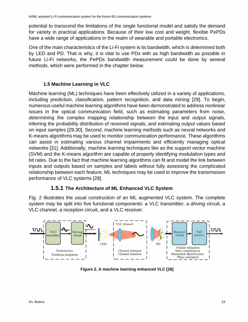
Fig. 2 illustrates the usual construction of an ML augmented VLC system. The complete
system may be split into five functional components: a VLC transmitter, a driving circuit, a
VLC channel, a reception circuit, and a VLC receiver.
Figure 2. A machine learning enhanced VLC [28]
AI/ML assisted Li-Fi communication system for the future 6G communication systems
Kh. Botirov 20
Typically, the transmitter and receiver are the ML-enhanced components.
The VLC transmitter performs digital signal processing operations such as encoding the
transmitting binary data, modulation, pre-equalization if necessary, up conversion, and
ultimately creation of the digital signal suitable for transmission to the transmitter circuit.
The driving circuit is composed of the following components: the arbitrary waveform
generator (AWG), the electronic ampLi-Fier (EA), the hardware pre-equalizer, the bias tee,
and, of course, the LED. The AWG completes the conversion of the produced digital signal
to analogue; the hardware pre-equalizer increases the useable bandwidth of the VLC
system; and the bias tee combines the bipolar zero-mean signal with the direct current bias
and so powers the LED.
A VLC system's channel might be either open space or underwater. The characteristic of
light attenuation in a channel is complex, causing confusion in the channel model and posing
difficulties in VLC systems.
The receiver circuit collects the light with the signal, which comprises the photodiode (PD),
the transimpedance amplifier (TIA), the equalization amplifier (EA), the attenuator, and the
oscilloscope. Together with the EA, the TIA amplifier the feeble electrical signal generated
from light by the PD. The attenuator regulates the amplitude of the amplified signal to ensure
that it fits within the dynamic range of the oscilloscope, which serves as the analogue-to-
digital converter.
At the receiver side, the VLC receiver performs digital signal processing via a number of
operations such as differential operation, down-conversion, post-equalization, demodulation,
and eventually decoding. The decoded binary data stream may be used to determine the
bitwise error rate, which indicates the overall transmission system's performance.

AI/ML assisted Li-Fi communication system for the future 6G communication systems
Kh. Botirov 21
2. METHODS
At the most fundamental level, Li-Fi systems are composed of LED transmitters that use the
intensity modulation concept to transform the incoming electrical signal to information prior
to transmission over the optical channel. The LED transmitter is capable of registering new
users and serving multiple users concurrently over the same optical channel, therefore
establishing a Li-Fi access point (AP). Photodetectors (PD) are used in the receivers to
convert falling light to optical current. Many contemporary receivers are portable and
equipped with the required gear for simulating the Li-Fi system's mobility and analyzing its
influence on receiver gain. A precise error assessment for packet reception may be achieved
using the receiver gain and the channel. The following section discusses a comprehensive
mathematical description of the Li-Fi systems' fundamental components.
2.1 Perovskite diodes
Metal halide perovskites are flexible, solution-processable semiconductors that have
excellent light emission and detection properties [36-41]. Perovskite LEDs, for example,
have exhibited external quantum efficiencies (EQEs) in excess of 20% [43-45], while
perovskite photodetectors have showed a low detection limit of 𝑠𝑢𝑏 − 𝑝𝑊 𝑐𝑚−2, as well as
nanosecond response times [40-42]. These advancements, along with the low Stokes shift
of perovskite materials, imply the possibility of developing high-performance solution-
processable dual-functional perovskite diodes that can act as both an optical transmitter and
receiver for wireless optical communications.
2.1.1 Perovskite LED
As a transmitter, PeLED, designed by [35], was considered in this work, and the PeLED
characteristics were based on the measurements results obtained by [35]. The PeLEDs were
made of an indium tin oxide (ITO)-coated glass/polyethylenimine ethoxylated (PEIE)-
modified zinc oxide (ZnO)/formamidinium lead iodide perovskite (50 nm) device structure.
/poly(9,9-dioctylfluorene-co-N-(4-butylphenyl)diphenylamine) (TFB) (40 nm)/molybdenum
oxide (MoOx) (70 nm)/gold (Au) (80 nm (Fig. 2). To reduce defects in the perovskite layer,
an effective passivation agent called 2,2′-(oxybis(ethylenoxy))diethylamine (ODEA) created
in 47 was utilized. As seen in Fig. 3 b, when the diode operates at a positive bias greater
than the turn-on voltage, electrons and holes are fed into the perovskite emitters, where they
undergo effective radiative recombination to create light. The optimized perovskite diode
(passivated with 30% ODEA and a precursor concentration of 0.13 M) exhibits optimal
electroluminescence (EL).

AI/ML assisted Li-Fi communication system for the future 6G communication systems
Kh. Botirov 22
a b
Figure 3. Schematic illustration of PeLEDs. a, Schematics of using perovskite diodes for inter- (left) and intra- (right) chip data communications. b, Schematics of the energy diagram of the perovskite diode under forward bias as an LED [35].
The authors initially exhibited the perovskite diodes' outstanding performance and rapid
reaction time as LEDs. The characterization findings indicate a low turn-on voltage of 1.3 V
and a maximum radiance of 314 W sr1 m2 (Fig. 3a). The maximal EQE value of 21.2 percent
is among the highest observed for perovskite LEDs [43-47]. Devices' excellent EL
performance is primarily due to the efficient passivation of ODEA to the iodide vacancy on
the perovskite crystal surfaces, which was previously studied in detail [47].
To characterize the response speed, the evolution of the EL intensity and current of square-
wave-driven diodes were observed (Fig. 3b). At a low frequency of 100 Hz, both the EL
intensity and current changes in lockstep with the driving voltage change. At a higher
frequency of 100 kHz, a little lag between the EL intensity and the voltage change can be
noticed, as well as noticeable current overshoots, which may be caused by the parasitic
capacitance's charging and discharging effects.
a b

AI/ML assisted Li-Fi communication system for the future 6G communication systems
Kh. Botirov 23
c d
Figure 4. Characterization of PeLEDs. a, EQE and radiance versus current density curves of the optimized perovskite LEDs. Inset: photograph of the LED driven by a 3.0 V bias. b, Transient EL intensity and current characterization of the perovskite LEDs at 100 Hz (top) and 100 kHz (bottom). c, Frequency response curves of the perovskite LED under different drive pulse voltages. d, Frequency response of perovskite LEDs with different device areas [35].
To verify this, the transient current curves with an exponential function were fitted and
determined that the charging and discharging processes have time constants of 120 and 172
ns, respectively (Fig. 4a). Using a serially linked resistance (5Ω), the capacitance of the
device is calculated to be 2.9±0.5 nF. This estimated value is consistent with the measured
value, indicating that the device's parasitic capacitance restricts the response speed when
used as an LED. Notably, passivation of trap states can increase not only EL efficiency but
also parasitic capacitance, therefore increasing response speed. Additionally, the EL
frequency response of the perovskite diode was evaluated when it was operated at various
voltages to establish the device's cutoff frequency. As seen in Fig. 4c, the cutoff frequency
increases as the driving voltage increases, reaching a maximum of 1.90 MHz at 4.0 V.
Increased cutoff frequency can be ascribed to quicker charge injection at a higher driving
voltage, similar to what is found in inorganic and organic diodes [48-50].
The following characteristics of PeLED were used in the Li-Fi system, Table 2.
Table 2. Parameters of PeLED [35]
Symbol Value Unit
Bandwidth 𝑓3𝑑𝐵, 𝑀𝐻𝑧 1.8 𝑀𝐻𝑧
PeLED surface 𝐴𝐿𝐸𝐷, 𝜇𝑚 7.25 𝜇𝑚
Angle at half-power 𝜃 𝜋
3 𝑑𝑒𝑔𝑟𝑒𝑒
Solid angle Ω 2𝜋(1 − cos(𝜃)) 𝑠𝑟
Radiance 𝐿𝑒 Figure 3a 𝑊𝑠𝑟−1𝑚−2
Radiated power 𝜙𝑒 ΩALED𝐿𝑒 𝑊

AI/ML assisted Li-Fi communication system for the future 6G communication systems
Kh. Botirov 24
2.1.2 Perovskite PD
Photodetectors have attracted considerable attention and have been utilized in a variety of
sectors, including industrial production, military affairs, biochemical detection, optical
communication, and scientific study.
The adaptability and availability of photodetectors are always determined by a few key
factors: photoresponse speed, sensitivity to low-light conditions, the detection band in which
photodetectors can detect light efficiently, and dynamic range response. The reaction time
or speed, spectral responsivity (𝑅), noise current, external quantum efficiency (𝐸𝑄𝐸), specific
detectivity (𝐷 ∗), and linear dynamic range (𝐿𝐷𝑅) of the photodetector are the essential
photodetector characteristics that should be utilized to assess these performance factors.
Recently, research into high-performance perovskite photodetectors has been a focal point
of attention in the fields of optoelectronics and high-quality imaging.
𝑅 =𝑒𝜂𝐸𝑄𝐸𝜆
ℎ𝑐 (1)
𝑤ℎ𝑒𝑟𝑒 𝑒 − 𝑒𝑙𝑒𝑐𝑡𝑟𝑜𝑛 𝑐ℎ𝑎𝑟𝑔𝑒, 𝜂𝐸𝑄𝐸 − 𝐸𝑄𝐸 𝑐𝑜𝑒𝑓𝑓𝑖𝑐𝑖𝑒𝑛𝑡, 𝜆 − 𝑤𝑎𝑣𝑒𝑙𝑒𝑛𝑔𝑡ℎ, ℎ − 𝑃𝑙𝑎𝑛𝑐 𝑐𝑜𝑛𝑠𝑡𝑎𝑛𝑡,
𝑐 − 𝑠𝑝𝑒𝑒𝑑 𝑜𝑓 𝑙𝑖𝑔ℎ𝑡.
Then the received electrical current can be obtained thought received optical power
𝑃𝑟𝑒𝑐 and PePD responsivity:
𝐼𝑟𝑒𝑐 = 𝑃𝑟𝑒𝑐𝑅 (2)
The total noise (Equation 1) of PePD expressed by the sum of thermal noise, shot
noise and dark current noise variances by following equations
𝜎𝑡𝑜𝑡𝑎𝑙2 = 𝜎𝑡ℎ𝑒𝑟𝑚𝑎𝑙
2 + 𝜎𝑠ℎ𝑜𝑡2 + 𝜎𝑑𝑎𝑟𝑘
2 (3)
The thermal noise variance of PePD with resistance 𝑅𝑙𝑜𝑎𝑑 = 50 𝑂ℎ𝑚 , at room
temperature 𝑇 = 300𝐾 is a Gaussian random process with zero mean. The bandwidth is
considered to be half of sampling frequency of the system due to the Nyquist theorem, and
we considered double sided power spectral density, that is why the bandwidth is at the range
between −𝑓𝑠𝑎𝑚𝑝
2;
𝑓𝑠𝑎𝑚𝑝
2.
𝜎𝑡ℎ𝑒𝑟𝑚𝑎𝑙2 =
2𝑘𝐵𝑇
𝑅𝑙𝑜𝑎𝑑𝐵𝑒 , 𝑤ℎ𝑒𝑟𝑒 𝑘𝐵 − 𝐵𝑜𝑙𝑡𝑧𝑚𝑎𝑛′𝑠 𝑐𝑜𝑛𝑠𝑡𝑎𝑛𝑡, 𝐵 − 𝑒𝑙𝑒𝑐𝑡𝑟𝑖𝑐𝑎𝑙 𝑏𝑎𝑛𝑑𝑤𝑖𝑑𝑡ℎ (4)
The shot noise variance is a white noise and in the limits set by the Nyquist theorem:
𝜎𝑠ℎ𝑜𝑡2 = 𝑒𝐼𝑟𝑒𝑐𝐵𝑒 , (5)
The dark current noise variance is also a Gaussian with zero mean, is caused by dark
current ,which is unwanted current or signal in a photodetector in the absence of incident
light, resulting from thermally excited electrons or leakage of current along the current path.
𝜎𝑑𝑎𝑟𝑘2 = 𝑒𝐼𝑑𝑎𝑟𝑘𝐵𝑒 (6)

AI/ML assisted Li-Fi communication system for the future 6G communication systems
Kh. Botirov 25
The PePD, which was considered in this work is from PeroCUBE project and its
characteristics were taken from the data provided by Eulambia Advanced Technologies ltd.
However, a number of measurements were performed in order to determine the operational
bandwidth of PePDs from PeroCUBE project.
2.1.3 PePD bandwidth measurements
All measurements were taken in the Optical Communications Laboratory of National and
Kapodistrian University of Athens under supervision of Dr.Kazazis and Dr.Raptis. The input
signal generator is Tektronix AFG1062 with 60MHz bandwidth, 2 output channels, 1 mVpp
to 10 Vpp output amplitude across full bandwidth and the oscilloscope is Tektronix TBS
1052B-EDU Digital oscilloscope, which is used to collect all measured data (one record
consist of 2500 points) and its bandwidth is 150MHz. There were two light sources in our
setup: OSRAM PLT5 510 (green laser diode) and ROHM RLD63NPC5 (red laser diode),
Table 3-4 describes light sources specifications. According to the specifications of devices
in the system design there is not limiting any factor for measurement of photodiodes
bandwidth.
Table 3. Characteristics of OSRAM PLT5 510 [52]
Symbol Value Unit
Output power 𝑃𝑜𝑝𝑡 10 𝑚𝑊
Operating current 𝐼𝑜𝑝 typ. 45 max. 75
𝑚𝐴
Operating voltage 𝑉𝑜𝑝 typ. 5.0 max. 6.6
𝑉
Peak wavelength 𝜆𝑝𝑒𝑎𝑘 min. 510 typ. 515
max. 530
𝑛𝑚
Spectral bandwidth (FWHM)
Δ𝜆 typ. 2 𝑛𝑚
Table 4. Characteristics of ROHM RLD64NPC5 [53]
Symbol Value Unit
Output power 𝑃𝑜𝑝𝑡 6 𝑚𝑊
Operating current 𝐼𝑜𝑝 typ. 24 max. 35
𝑚𝐴
Operating voltage 𝑉𝑜𝑝 typ. 2.2 max. 2.7
𝑉
Peak wavelength 𝜆𝑝𝑒𝑎𝑘 min. 630 typ. 635
max. 645
𝑛𝑚
PinPD Reverse Voltage
𝑉𝑟 max. 20 𝑉

AI/ML assisted Li-Fi communication system for the future 6G communication systems
Kh. Botirov 26
a b
Figure 5. a, PePD bandwidth measurements design. b, The bandwidth measurement process using
OSRAM PLT5 510 laser as a source and ThorLabs PDA25K-EC as a detector.
The starting stage of the measurement was check if there are any limiting devices in system setup in term of frequency response. The system was validated by measuring reference photodiode ThorLabs PDA25K-EC, which is operating in the range of 150-550 nm and its bandwidth is 7.5Mhz. The PDA25K(-EC) is an amplified, switchable-gain Gallium Phosphide (GaP) detector designed to detect light signals with a wavelength range of 150–550 nm. The user may adjust the gain in ten-dB levels through an eight-position rotary switch. A buffered output drives 50 Ω load impedances up to 5 V. The PDA25K(-EC) incorporates a low-noise, low-offset, high-gain transimpedance amplifier with a gain control range of 70 dB. Adjust the gain by twisting the gain control knob on the unit’s top side. There are eight gain settings, each raised by ten decibels. It is critical to keep in mind that as the gain increases, the bandwidth decreases [51].
Table 5 Specifications of reference PD PDA25K-EC [51]
Symbol Value Unit
Detector - GaP PIN
Active Area - 2.2 x 2.2 (4.8 𝑚𝑚2) 𝑚𝑚
Wavelength Range 𝜆 150 to 550 𝑛𝑚
Peak Wavelength 𝜆𝑝 440 (Typ.) 𝑛𝑚
Peak Response ℜ(𝜆𝑝) 0.12 (Typ.) 𝐴/𝑊
Amplifier GBP - 25 𝑀𝐻𝑧
Output Impedance - 50 Ω
Max Output Current 𝐼𝑂𝑈𝑇 100 𝑚𝐴
Load Impedance - 50 to Hi-Z Ω
Gain Adjustment
Range
- 0 to 70 𝑑𝐵
Gain Steps - 8 x 10 Steps 𝑑𝐵
Output Voltage 𝑉𝑂𝑈𝑇 0 to 5 (50 Ω)
0 ot 10 (Hi-Z)
𝑉
The measurement of PDA25K-EC was done by step-by-step increasing the input signal
frequency and there were four measurements with following PD amplifier values: 0dB; 10dB;
20dB; 40dB. The calculation of the 3dB bandwidth 𝑓3𝑑𝐵 done by (Equation 7)

AI/ML assisted Li-Fi communication system for the future 6G communication systems
Kh. Botirov 27
𝑓3𝑑𝐵 = 𝑓𝑟 𝑖𝑓10 log(𝑉𝑟.𝑚𝑎𝑥2 ) − 10 log(𝑉𝑟
2) = 3𝑑𝐵 (7)
,where 𝑉𝑟.𝑚𝑎𝑥 is maximum received Amplitude, 𝑉𝑟 is received Amplitude in certain
input signal frequency 𝑓𝑟
The photodetector can be considered as a low pass filter with frequency response:
|𝐻(𝑓)|2 =1
1 + (𝑓
𝑓3𝑑𝐵)
2 ( 8)
The source of the input signal is OSRAM PLT5 510 operating in 515nm wavelength and the
input signal parameters are same for all values of amplifier and equal to: offset is 6.5V and
amplitude is 1V. The results of the measurements proofs, that the system design is valid for
the relevant bandwidth measurement of PePDs, since the result of measurements are close
enough to the reference values from the datasheet of PDA25-EC, Table 6.
Table 6. Reference commercial PD measurement results
Amplitude, 𝒅𝑩 Measured
Bandwidth, 𝑴𝑯𝒛
Reference
Bandwidth, 𝑴𝑯𝒛
0 7.75 7.5
10 3.65 3.5
20 1.55 1
40 0.255 0.1
There are 3 methods of PD bandwidth calculations via following measurements were
considered:
• Peak voltage measurement - The measurement is done by increasing the input
signal frequency step by step until we reached the 3dB frequency and kept
going on further till reaching fluctuations due to system design.
• Rise time measurement - For the same setup we measured high, low, peak to
peak Voltage values. The input signal is pulse signal, and its offset and
amplitude differ for each PePD measurement and the frequency is also kept
different. From obtained voltage values we can find 10% an 90% pulse rise
time and get 𝑡𝑟𝑖𝑠𝑒, then 𝑓3𝑑𝐵 can be calculated by Equation 9.
𝑓3𝑑𝐵 ≈ 0.35/trise (9)
• Fast Fourier Transform (FFT) measurement – the input signal is pulsed signal
with certain duty cycle and frequency. The saved data points are output of FFT
function of the oscilloscope.

AI/ML assisted Li-Fi communication system for the future 6G communication systems
Kh. Botirov 28
There were 4 different PePD bandwidth to be measured by above-described methods
and their specification are described in Table 6. PePDs can be categorized by their
surface size and the measurements analysis shows clear difference in the
performance of PePDs.
Table 7. Characteristics of PePDs
PePDs Surface,
𝒎𝒎𝟐
Peak wavelength,
nm
Illumination 𝑱𝒔𝒄, 𝒎𝑨/𝒄𝒎𝟐
𝑽𝒐𝒄, 𝒎𝑽 𝑱𝒅𝒓, 𝒎𝑨/𝒄𝒎𝟐
PePD 3 small
107 540 Light 18.66001
1014.75
1.871106
PePD 4 small
107 540 Light 17.64519
965.4591
1.959539
PePD 2 large
1460 540 Light 3.4717
5438.245
0.4021
PePD 3 large
1460 590 Light 3.4616
5482.885
0.4113
It can be noticed that the characteristics of PePD3 small and PePD4 small are relatively
similar, whereas PePD2 large and PePD3 large also have same performance both in
𝐽𝑠𝑐 𝑣𝑠 𝑉𝑜𝑐 and EQE vs wavelength relationship. From Figure 6, it can be seen that the EQE
of large PePDs at the range of 520 – 600 nm are showing promising ~96% and small PePDs
reaches their peak EQE values ~90% at the range of 505-530nm.
Figure 6. EQE versus wavelength relationship of PePDs
The bandwidth measurement of all four PePDs starts from Peak voltage measurement using
two lasers mentioned above. Input signal parameters as offset and amplitude are kept same
0
0.1
0.2
0.3
0.4
0.5
0.6
0.7
0.8
0.9
1
320 360 400 440 480 520 560 600 640 680 720 760 800
NO
RM
ALI
ZED
EQ
E
WAVELENGTH
PePD2 large PePD3 large PePD3 small PePD4 small

AI/ML assisted Li-Fi communication system for the future 6G communication systems
Kh. Botirov 29
per laser. For OSRAM PLT5 510 (green laser), the offset was equal to 6.4V and the
amplitude was equal to 220mVpp (peak-to-peak) and for ROHM RLD64NPC5 the offset was
set at 4.3V and the amplitude was 300mVpp. The Figure 6 shows the plots of ideal
conventional RC filter and PePD4 small Peak voltage measurements data, it can be seen
from Appendix II, that all PePDs are acting like a RC filter as well as LED.
Figure 7. Electrical power response vs Frequency of PePD3 small at 515nm.
PePDs bandwidth measurement thought its response speed by using Equation (9). In general, the rise time is defined as the time for the photocurrent to increase from 10% to 90% of the peak when photocurrent arrives at a stable state after accepting illumination. This type of measurement is considered as an estimation of bandwidth. The input signal was a pulsed electrical signal with following parameters offset and amplitude, which were same as for Peak voltage measurement, except frequency, which was a fixed value for each PePD. From Figure 7b, it can be seen that measured rise is equals to the 𝑡𝑟𝑖𝑠𝑒 = 14.8 𝜇𝑠, using Equation 2, we will estimate 19kHz bandwidth for PePD3 small.
a b
Figure 8. Rise time measurement of pulsed signal of PePD3 small at 515nm
AI/ML assisted Li-Fi communication system for the future 6G communication systems
Kh. Botirov 30
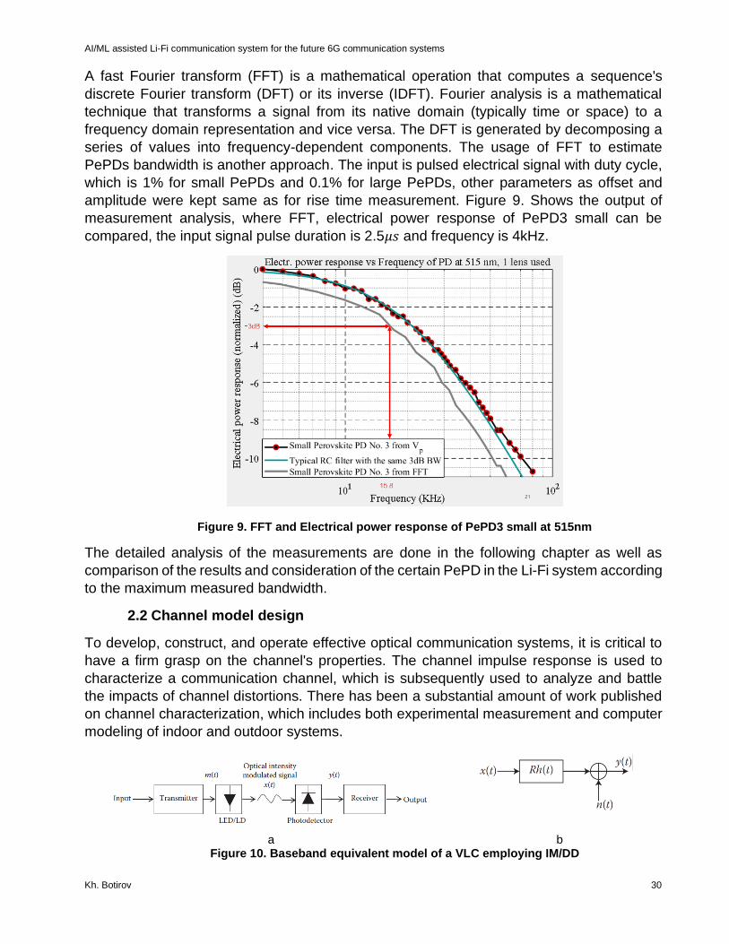
A fast Fourier transform (FFT) is a mathematical operation that computes a sequence's
discrete Fourier transform (DFT) or its inverse (IDFT). Fourier analysis is a mathematical
technique that transforms a signal from its native domain (typically time or space) to a
frequency domain representation and vice versa. The DFT is generated by decomposing a
series of values into frequency-dependent components. The usage of FFT to estimate
PePDs bandwidth is another approach. The input is pulsed electrical signal with duty cycle,
which is 1% for small PePDs and 0.1% for large PePDs, other parameters as offset and
amplitude were kept same as for rise time measurement. Figure 9. Shows the output of
measurement analysis, where FFT, electrical power response of PePD3 small can be
compared, the input signal pulse duration is 2.5𝜇𝑠 and frequency is 4kHz.
Figure 9. FFT and Electrical power response of PePD3 small at 515nm
The detailed analysis of the measurements are done in the following chapter as well as
comparison of the results and consideration of the certain PePD in the Li-Fi system according
to the maximum measured bandwidth.
2.2 Channel model design
To develop, construct, and operate effective optical communication systems, it is critical to
have a firm grasp on the channel's properties. The channel impulse response is used to
characterize a communication channel, which is subsequently used to analyze and battle
the impacts of channel distortions. There has been a substantial amount of work published
on channel characterization, which includes both experimental measurement and computer
modeling of indoor and outdoor systems.
a b Figure 10. Baseband equivalent model of a VLC employing IM/DD
AI/ML assisted Li-Fi communication system for the future 6G communication systems
Kh. Botirov 31
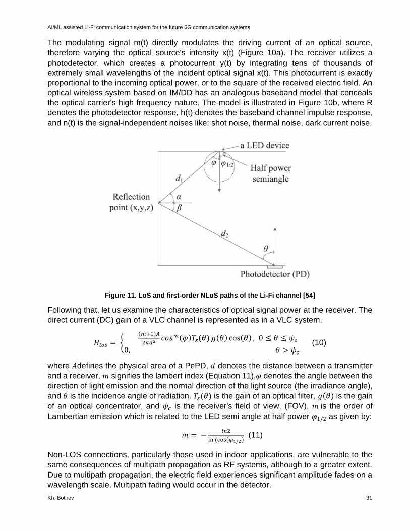
The modulating signal m(t) directly modulates the driving current of an optical source,
therefore varying the optical source's intensity x(t) (Figure 10a). The receiver utilizes a
photodetector, which creates a photocurrent y(t) by integrating tens of thousands of
extremely small wavelengths of the incident optical signal x(t). This photocurrent is exactly
proportional to the incoming optical power, or to the square of the received electric field. An
optical wireless system based on IM/DD has an analogous baseband model that conceals
the optical carrier's high frequency nature. The model is illustrated in Figure 10b, where R
denotes the photodetector response, h(t) denotes the baseband channel impulse response,
and n(t) is the signal-independent noises like: shot noise, thermal noise, dark current noise.
Figure 11. LoS and first-order NLoS paths of the Li-Fi channel [54]
Following that, let us examine the characteristics of optical signal power at the receiver. The
direct current (DC) gain of a VLC channel is represented as in a VLC system.
𝐻𝑙𝑜𝑠 = {(𝑚+1)𝐴
2𝜋𝑑2 𝑐𝑜𝑠𝑚(𝜑)𝑇𝑠(𝜃) 𝑔(𝜃) cos(𝜃) , 0 ≤ 𝜃 ≤ 𝜓𝑐
0, 𝜃 > 𝜓𝑐 (10)
where 𝐴defines the physical area of a PePD, 𝑑 denotes the distance between a transmitter
and a receiver, 𝑚 signifies the lambert index (Equation 11),𝜑 denotes the angle between the
direction of light emission and the normal direction of the light source (the irradiance angle),
and 𝜃 is the incidence angle of radiation. 𝑇𝑠(𝜃) is the gain of an optical filter, 𝑔(𝜃) is the gain
of an optical concentrator, and 𝜓𝑐 is the receiver's field of view. (FOV). 𝑚 is the order of
Lambertian emission which is related to the LED semi angle at half power 𝜑1/2 as given by:
𝑚 = −𝑙𝑛2
ln (cos(𝜑1/2) (11)
Non-LOS connections, particularly those used in indoor applications, are vulnerable to the
same consequences of multipath propagation as RF systems, although to a greater extent.
Due to multipath propagation, the electric field experiences significant amplitude fades on a
wavelength scale. Multipath fading would occur in the detector.

AI/ML assisted Li-Fi communication system for the future 6G communication systems
Kh. Botirov 32
The channel DC gain of the first reflection is shown as:
𝐻𝑛𝑙𝑜𝑠 = {
(𝑚+1)𝐴
2𝜋𝑑12𝑑2
2 𝜌𝑑𝐴𝑤𝑎𝑙𝑙 𝑐𝑜𝑠𝑚(𝜑)𝑐𝑜𝑠(𝛼)𝑐𝑜𝑠(𝛽)𝑇𝑠(𝜃) 𝑔(𝜃) cos(𝜃) , 0 ≤ 𝜃 ≤ 𝜓𝑐
0, 𝜃 > 𝜓𝑐 (12)
where 𝑑1 represents the distance between the LED and the reflection point, 𝑑2 denotes the
distance between the reflection point and the receiver, and 𝜌 signifies the reflection
coefficient, 𝑑𝐴𝑤𝑎𝑙𝑙 signifies the emission area of a micro surface, 𝜑 denotes the radiation
angle of reflection points, 𝛼 expresses the incidence angle of reflection points, 𝛽 denotes the
receiver's radiation angle, and denotes the receiver's incidence angle.
2.2.1 The properties of indoor environment
At the moment, Li-Fi systems are mostly used in an indoor setting, where their channel
models are influenced by a variety of factors, including the design of the light source, the
location of receivers, the geometry of the space, and the effect of various reflectors. This
section will examine the room model, and interior environment reflection characteristics.
Typically, the room model is denoted by the L, H, W, where L is the length, W represents the
breadth, and H represents the height. Length and breadth were typically identical in the
majority of trials [53].
In the system we considered room dimensions are 3mx3mx3m, which means it’s a cube and
we have used 4 PeLED-arrays in the following locations (Table 8). The refractive index of
walls is equal to the reflectance of the white concrete 0.4, the refractive index of pine wood
door is 0.9 and window has a 0.51 reflectance (Figure 12).
Figure 12. Visualization of the room design
Table 8. PeLED arrays location
LED array Length, 𝒎 Width, 𝒎 Height, 𝒎
PeLED array 1 1 1 1.25
PeLED array 2 -1 1 1.25
PeLED array 3 -1 -1 1.25
PeLED array 4 1 -1 1.25
3 m
3 m
3 m
AI/ML assisted Li-Fi communication system for the future 6G communication systems
Kh. Botirov 33
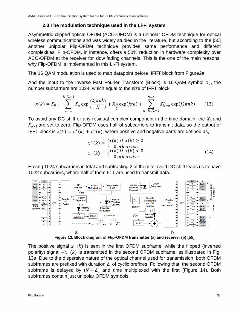
2.3 The modulation technique used in the Li-Fi system
Asymmetric clipped optical OFDM (ACO-OFDM) is a unipolar OFDM technique for optical
wireless communications and was widely studied in the literature, but according to the [55]
another unipolar Flip-OFDM technique provides same performance and different
complexities. Flip-OFDM, in instance, offers a 50% reduction in hardware complexity over
ACO-OFDM at the receiver for slow fading channels. This is the one of the main reasons,
why Flip-OFDM is implemented in this Li-Fi system.
The 16 QAM modulation is used to map datapoint before IFFT block from Figure2a.
And the input to the Inverse Fast Fourier Transform (Block) is 16-QAM symbol 𝑋𝑘, the
number subcarriers are 1024, which equal to the size of IFFT block.
𝑥(𝑘) = 𝑋0 + ∑ 𝑋𝑛 exp (2𝑗𝜋𝑛𝑘
𝑁) + 𝑋𝑁
2exp(𝑗𝜋𝑘) +
𝑁 /2−1
𝑛=1
∑ 𝑋𝑁−𝑛∗
𝑁−1
𝑛=𝑁 /2+1
exp(𝑗2𝜋𝑛𝑘) (13)
To avoid any DC shift or any residual complex component in the time domain, the 𝑋0 and
𝑋𝑁/2 are set to zero. Flip-OFDM uses half of subcarriers to transmit data, so the output of
IFFT block is 𝑥(𝑘) = 𝑥+(𝑘) + 𝑥−(𝑘), where positive and negative parts are defined as,
𝑥+(𝑘) = {𝑥(𝑘) 𝑖𝑓 𝑥(𝑘) ≥ 0
0 𝑜𝑡ℎ𝑒𝑟𝑤𝑖𝑠𝑒
𝑥−(𝑘) = {𝑥(𝑘) 𝑖𝑓 𝑥(𝑘) < 0
0 𝑜𝑡ℎ𝑒𝑟𝑤𝑖𝑠𝑒
(14)
Having 1024 subcarriers in total and subtracting 2 of them to avoid DC shift leads us to have
1022 subcarriers, where half of them 511 are used to transmit data.
a b
Figure 13. Block diagram of Flip-OFDM transmitter (a) and receiver (b) [55]
The positive signal 𝑥+(𝑘) is sent in the first OFDM subframe, while the flipped (inverted
polarity) signal −𝑥−(𝑘) is transmitted in the second OFDM subframe, as illustrated in Fig.
13a. Due to the dispersive nature of the optical channel used for transmission, both OFDM
subframes are prefixed with duration Δ of cyclic prefixes. Following that, the second OFDM
subframe is delayed by (𝑁 + Δ) and time multiplexed with the first (Figure 14). Both
subframes contain just unipolar OFDM symbols.

AI/ML assisted Li-Fi communication system for the future 6G communication systems
Kh. Botirov 34
Figure 14. Flip-OFDM unipolar frame [55]
The two received subframes are used to reconstruct the bipolar OFDM frame at the Flip-
OFDM receiver, as illustrated in Fig. 13b. After removing the cyclic prefixes associated with
each OFDM subframe, the original bipolar signal is regenerated as, where 𝑦+(𝑘) and 𝑦−(𝑘)
denote the first and second subframe time samples, respectively. Fast Fourier Transform
(FFT) operations are used to recreate the bipolar signal in order for the receiver to detect the
transmitted data symbols.
2.4 Applying Deep Learning to reduce nonlinearities at the receiver.
Deep learning (DL), a type of machine learning technique based on neural networks (NN),
has lately regained great momentum following the achievement of ground-breaking
performance in computer vision, natural language processing, and automated speech
recognition. Additionally, a Multi Layer Perception (MLP) has been implemented in wireless
physical layer communications, MLP is a class of supervised feedforward Deep Neural
Networks (DNN) ,
In comparison to conventional OFDM, the decoder at the receiver uses received signals after
FFT block to mitigate nonlinearities caused by the LED nonlinearities primarily stems from
the Electrical-Optical conversation, PD total noise influence and channel response. The
proposed algorithm consists of the dense layers, normalization and activation functions.
Additionally, the dropout layer may be used after the dense layer to solve the over-fitting
problem and improve the MLP model's generalization capacity, particularly when the number
of sub-layers and hyper-parameters is quite big. It should be noted that the Dl model layers
are trained concurrently with the IM/DD channel, and that different numbers of neurons can
be used in different sub-layers to reduce network complexity.
Figure 15. MLP consistion of 2 hidden layers

AI/ML assisted Li-Fi communication system for the future 6G communication systems
Kh. Botirov 35
2.4.1 The dataset preparation
The output of 16-QAM modulation is considered as a labels 𝑡, while the output of FFT block
at the receiver is chosen as a noisy dataset, which has a size of 𝑁 = 51100 data points. The
since our dataset represented by complex numbers, the primary task was to split real and
imaginary parts of each datapoints both for labels and for the noisy dataset. As a result,
dataset became a (51100,2) matrix, where real and imaginary parts of datapoints are
features. In order to have larger dataset, feature extraction was done by adding the absolute
of the datapoint, the square of both real and imaginary parts, which provided 3 more features
and concatenation of all features transferred noisy dataset into the matrix with size of 𝒫 =
(51100,5).
Model architecture
As a DNN the MLP was used, which consists of 𝑘 – hidden layers and single input and output
layers, meaning the whole model will have 𝑘 + 2 layers in total, Figure 15. As a hidden layers
Dense fully connected layers are used with activation function Sigmoid. Let 𝒟𝑙 denotes the
number of neurons of the 𝑙 −th layer, then 𝑡𝑙 – is the input to the 𝑙-th dense layer, then the
outputs can be expressed by Equation 16.
ℎ𝑙 = 𝑊𝑙𝑡𝑙 + 𝑏𝑙 (15)
Where 𝑊𝑙 ∈ ℝ𝒟𝑙𝑥𝒫 and 𝑏𝑙 ∈ ℝ𝒟𝑙 are the weight matrix and bias vector for the 𝑙-th dense
layer, respectively. Then, ℎ𝑙 l goes via the normalization unit, which normalizes the activation
function's input and maintains the same distribution for each sub-input layer's during MLP
training. The batch normalizing technique is used in this work, and the related outputs may
be computed as:
(ℎ𝑙)𝐵𝑎𝑡 =𝛼𝑙(ℎ𝑙 − 𝔼{ℎ𝑙})
√𝜎ℎ𝑙
2 + 𝜁
+ 𝛽𝑙 (16)
Where (. )𝐵𝑎𝑡 denotes the output of Batch normalization, 𝛼𝑙 and 𝛽𝑙 are the scaling and shift
factors, respectively. Additionally,𝜁 is always set to a value near to zero to avoid the
denominator becoming zero. Notably, the proper 𝛼𝑙 and 𝛽𝑙 can also be learnt during the
training phase. The (ℎ𝑙)𝐵𝑎𝑡 Bat is then sent into the activation function 𝜌𝑙, which generates
the outputs of the 𝑙-th sub-layer.
If (ℎ𝑙)𝐵𝑎𝑡 is a positive real value, then the Sigmoid activation function creates the same
values as the (ℎ𝑙)𝐵𝑎𝑡 . But beyond that, linear activation is utilized for the final sub-layer
since the primary purpose of the MLP net's outputs is to generate I-Q samples from the learnt
dataset. The output layer uses Tanh activation function and the result is predicted dataset
𝑡^ ∈ ℝ2𝑁 , which is divided into two parts according to their odd and even index, and later
concatenate them into complex I-Q symbol.
𝑡^ = φℒ{(𝑊ℒ𝑡ℒ + 𝑏ℒ)𝐵𝑎𝑡} (17)
Where ℒ is number of dense layers in DNN.

AI/ML assisted Li-Fi communication system for the future 6G communication systems
Kh. Botirov 36
2.4.2 DNN training
During the training stage, the proposed DNN is tuned to maximize end-to-end performance
by adjusting the parameters Θ = {𝑊, 𝑏} to bring the reconstruction 𝑡^ closer to the raw 𝑡.
The relationship between 𝑡 and 𝑡^ can be quantified using the mean square error (MSE), as
given by
𝑀𝑆𝐸(𝑡, 𝑡^) = |𝑡 − 𝑡|22 (18)
While alternative loss functions were considered, they did not give any discernible
improvements over the MSE.
The Adam stochastic algorithm was chosen as a traditional optimization method. The
maximum number of training epochs utilized in the DNNs applications is 100, and the
accuracy was computed after each training epoch using a dataset produced independently.
To avoid overfitting and to remove the possibility of data sequences being periodic, the
complete dataset contain is split into two subsets: training, testing by stratified K-fold with
number of splits equal to 10, enabled shuffling and random state set at 1. Additionally, to
minimize overfitting, during the training phase, a dropout layer with probability equal to 0.2
was added to the last hidden layer in each DNN topology.
Table 9. Topology of DNN
Layer #
Layer type Number of
neurons
Activation function
1 Input (shape 5)
2 Dense 250 Sigmoid
3 BatchNormalization()
4 Dense 250 Sigmoid
5 BatchNormalization()
6 Dense 250 Sigmoid
7 Dropout (0.2)
8 Output 2
Assuming the goal of training is to minimize loss, the early stopping function with patience
equal to 10 was added during the DNN training, in order to stop training when a monitored
metric validation accuracy is stopped improving.
The overall major work was done in the PePDs’ bandwidth measurement and analysis of
those measurement to have proper data to simulate Li-Fi communication system, which
generates relatively realistic data. The simulated dataset from Li-Fi simulation was used to
train DNN to mitigate the noises mainly caused by the optoelectronic components of the
system.

AI/ML assisted Li-Fi communication system for the future 6G communication systems
Kh. Botirov 37
3. RESULTS AND DISSCUSSION
In this section the PePD’s measurement analysis is provided and the influence of DNN model
to the reduction of BER is also contemplated.
3.1 PePD’s measurement results
The proper PD bandwidth measurement environment was designed and checked by
reference PD, before measure of the bandwidth of PePDs, from Table 6. It can be seen that
the measured 𝑓3𝑑𝐵 of PDA25K-EC is higher than the ones from official factory datasheets at
all 4 values of TIA ampLi-Fier, which leads us conclude that there isn’t any limiting device
for bandwidth measurement in our setup, due to the fact that we could measure 7.75 MHz
without received signal ampLi-Fication. At least, we can assume that the proved potential
bandwidth of our setup is 7.75 MHz. Knowing, that we do not have any limiting factor we
performed 3 different ways of PePDs bandwidth estimation and from our measurement
analysis we can conclude, that 3dB frequency estimation from peak voltage measurement
can be considered as a reference method, the input signal frequency steps between
measurements for small PePDs were considered to be almost same and we used almost
identical frequency steps for large PePDs bandwidth measurements. From the analysis of
obtained data, we can clearly see that pulse rise time measurement outputs were relatively
close to reference bandwidth values. However, FFT measurement is rough approximation of
bandwidth, the outcomes from FFT measurements are underestimated. Each measurement
is a dataset containing 2500 samples and data processing techniques were done to extract
necessary data.
The estimation of PePDs bandwidth from received peak voltage measurement is regarded
as a reference measurement. This is method is the most accurate one among others, since
the estimation of 𝑓3𝑑𝐵 is based on the setoff 50-60 measurements, where the frequency of
input signal is increasing step-by-step. The probability of the error, because received signal
fluctuation, are minimized and the detection of anomaly measured peak voltage can be
detect without any complexity. The important think was to compare the power response of
PePDs obtained from measured peak voltage values with ideal RC filter with same 𝑓3𝑑𝐵,
which shows the quality of measurement as well as the correctness of the measurement, as
an example we can see Figure 6, where power response of PePD 3 small is almost identical
with RC filter behavior.

AI/ML assisted Li-Fi communication system for the future 6G communication systems
Kh. Botirov 38
Table10. PePDs bandwidth estimation via peak voltage measurement
PePD Offset, V mV pp 3dB frequency, Hz Laser
wavelength,
nm
surface, mm^2
3 small 6.4 220 21000 515 105
3 small 4.3 300 25500 635 105
4 small 6.4 220 30500 515 105
4 small 4.3 300 36250 635 105
2 large 6.4 220 162.5 515 1440
2 large 4.3 300 437.5 635 1440
3 large 6.4 220 450 515 1440
3 large 4.3 300 487.5 635 1440
Another approach to obtain PePDs bandwidth values was PePDs rise time measurement,
this method is approximation and one measurement was performed per PePD. The reliance
of this method is checked by comparison with results obtained from above mentioned
method. From Table 11, it can be seen the 𝑓3𝑑𝐵 values per all 4 PePDs under both light
sources.
Table11. PePDs bandwidth estimation via rise time measurement
PePD High
value ,
mV
Low
valu
e,
mV
Peak-to-
peak
value,
mV
𝑽𝟏𝟎%, 𝒎𝑽 𝒂𝒏𝒅
𝑻𝟏𝟎%, µ𝒔
𝑽𝟗𝟎%, 𝒎𝑽 𝒂𝒏𝒅
𝑻𝟗𝟎%, µ𝒔
3dB
frequency
, Hz
Offset,
V
mVpp Laser
wavelength,
nm
Frequency,
kHz
3
small
5.9 -6 11.9 -4.8 at
2751
4.75 at 2769 19021 6.4 220 515 4
3
small
2.955 -
2.62
4
5.5795 -2.0665 at
8201.8
2.3971 at
8216.6
23648 4.3 300 635 5
4
small
5.9757 -
6.06
0
12.0364 -4.8571 at
0.76
4.7721 at
12.04
31028 6.4 220 515 8
4
small
5.26 -
4.96
10.22 -3.93 at
0.76
4.24 at
14.16
26119 4.3 300 635 7
2
large
67.01 -68 135 -54 at 8 53 at 1668 210 6.4 220 515 0.05
2
large
25.2 -
25.6
50.8 -20.5 at 2 20.1 at 317 382 4.3 300 635 0.1
3
large
57.8 -50 107.8 -39 at 8 47 at 1124 313 6.4 220 515 0.05
3
large
29.5 -
29.6
59.1 -23.6 at 0 23.6 at 880 397 4.3 300 635 0.1

AI/ML assisted Li-Fi communication system for the future 6G communication systems
Kh. Botirov 39
The last technique used to quantify the PePDs bandwidth was usage of built-in FFT function
in oscillograph. This method is a rough estimation of 𝑓3𝑑𝐵 frequency of PePDs and the results
of FFT method can’t be considered in Li-Fi system. All values of PePDs bandwidth
calculation using FFT method are underestimated and not accurate with reference ones.
Table 12. PePDs bandwidth estimation via FFT measurement
PePD 3dB
frequency,
Hz
Input
signal
frequency,
Hz
Offset, V mVpp Duty cycle Wavelength
3 small 15869 4000 6.4 220 1% 515
3 small 17089 5000 4.3 300 1% 635
4 small 25634 8000 6.4 220 1% 515
4 small 22071 7000 4.3 300 1% 635
2 large 36 50 6.4 220 0.1% 515
2 large 73 100 4.3 300 0.1% 635
3 large 221 100 6.4 220 0.1% 515
3 large 73 100 4.3 300 0.1% 635
Comparing the results of the measurements, it can be concluded, that the large PePDs are definitely not designed for usage within wireless communication system and their main purpose is to be implemented in future Perovskite material based solar cells and their EQE is larger than the small PePDs’ due to Figure 5. According to the 𝑓3𝑑𝐵 values of both small PePDs, the small PePDs showed up higher bandwidth under red laser and PePD4 small has highest measured bandwidth 𝑓3𝑑𝐵 = 36.25kHz with surface size of PePD4 𝐴𝑝𝑑 = 107𝑚𝑚2 ,
however from Figure 5 we can see the EQE of small PePDs at 635nm is slightly lower than at 515nm. One of the main advantages of Li-Fi systems is its bandwidth, that is why we can not use PePDs from our laboratory, as a solution hypothetical smaller size of PePD4 small is used to meet bandwidth requirements of the system. The bandwidth and surface size of potential PePD is calculated as follows:
𝐴𝑃𝑒𝑃𝐷 =𝐴𝑃𝑒𝑃𝐷4
𝜅= 7.84 𝑚𝑚2, 𝑤ℎ𝑒𝑟𝑒 𝜅 =
𝐴𝑃𝑒𝑃𝐷2
𝐴𝑃𝑒𝑃𝐷4; (19)
𝑓3𝑑𝐵𝑃𝑒𝑃𝐷 =
𝑓3𝑑𝐵𝑃𝑒𝑃𝐷4
𝜄= 2695 𝑘𝐻𝑧 = 2.695 𝑀𝐻𝑧, 𝑤ℎ𝑒𝑟𝑒 𝜄 =
𝑓3𝑑𝐵𝑃𝑒𝑃𝐷4
𝑓3𝑑𝐵𝑃𝑒𝑃𝐷2
; (20)
The net-effects of the transmitter and receiver lead to a system with low-pass characteristic. The dark current value for the PePD is calculated using values from Table 7 and equals to 𝐼𝑑𝑟 = 1.635 𝜇𝐴.
The minimum required distance between the transmitter and the receiver with single LED and PD is to achieve BER lower than 10−4 is only 0.3 meters, which is not suitable for genuine Li-Fi systems, Figure 15. The solution is to increase radiated power by adding more
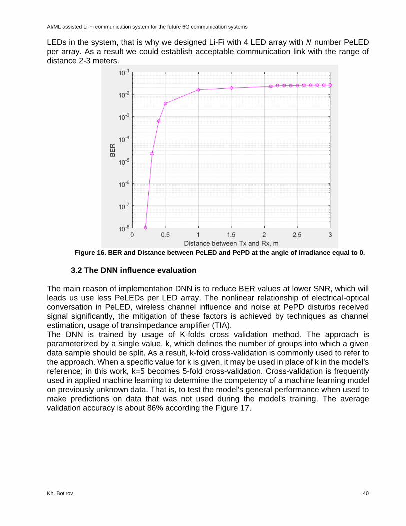
AI/ML assisted Li-Fi communication system for the future 6G communication systems
Kh. Botirov 40
LEDs in the system, that is why we designed Li-Fi with 4 LED array with 𝑁 number PeLED per array. As a result we could establish acceptable communication link with the range of distance 2-3 meters.
Figure 16. BER and Distance between PeLED and PePD at the angle of irradiance equal to 0.
3.2 The DNN influence evaluation
The main reason of implementation DNN is to reduce BER values at lower SNR, which will leads us use less PeLEDs per LED array. The nonlinear relationship of electrical-optical conversation in PeLED, wireless channel influence and noise at PePD disturbs received signal significantly, the mitigation of these factors is achieved by techniques as channel estimation, usage of transimpedance amplifier (TIA). The DNN is trained by usage of K-folds cross validation method. The approach is parameterized by a single value, k, which defines the number of groups into which a given data sample should be split. As a result, k-fold cross-validation is commonly used to refer to the approach. When a specific value for k is given, it may be used in place of k in the model's reference; in this work, k=5 becomes 5-fold cross-validation. Cross-validation is frequently used in applied machine learning to determine the competency of a machine learning model on previously unknown data. That is, to test the model's general performance when used to make predictions on data that was not used during the model's training. The average validation accuracy is about 86% according the Figure 17.

AI/ML assisted Li-Fi communication system for the future 6G communication systems
Kh. Botirov 41
Figure 17. The 5-Fold cross validation of DNN
The influence of nonlinearities can be observed in the constellation of received 16-QAM signals. It can be noticed from figures below, that raw received signals after FFT block are highly noisy and Figure 18b, shows the high performance of DNN to mitigate the phase shifts and inter symbol interference (ISI).
a b
Figure 18. Constellation of received 16-QAM signal before and after DNN
The evaluation the DNN performance was done by using another supervised classification algorithm Support-Vector Machines (SVM), which is widely used in the optical communications to solve problems like modulation recognition, etc. As a kernel of SVM, Radial Basis Function (RBF)’ was chosen, since linear and polynomial kernels conceded to the RBF, the labels were preprocessed by K-means, to classify them into 16 clusters.
0.835
0.84
0.845
0.85
0.855
0.86
0.865
0.87
0.875
0.88
0.885
0.89
0 1 2 3 4 5 6
Val
idat
ion
acc
ura
cy, %
Kth- fold

AI/ML assisted Li-Fi communication system for the future 6G communication systems
Kh. Botirov 42
a b
Figure 19. a. BER vs Number of PeLEDs per array, b. BER vs SNR
Fig. 19 compares the BER performance of a SVM with a RBF kernel, proposed DNN with fully-connected Dense layers and Li-Fi system without any ML assistance. As can be observed, the Li-Fi system's BER reduces as the SNR grows, but there is still a notable difference between the RBF SVM's performance and DNN, SVM perform slightly lower than just Li-Fi. It can be seen that the SVM BER decreases as the SNR increases, but there is still a gap from the performance of DNN. It is can be noticed, that the results of BER without DNN shows almost same values at approximately 2dB higher SNR, Figure 19b. The new proposed DNN algorithm is improving BER by average 5 times, while SVM is showing about 2.5 times BER improvement. Figure 17 compares the received constellations of system with DNN and without DNN at SNR equal to 25dB. The DNN-based equalizer is effective in mitigating nonlinearity in a Li-Fi communication system. However, the dataset generated by the designed Li-Fi system is not sufficient enough and the Li-Fi system with Perovskite material-based devices should be performed furthermore to generate valuable dataset for future ML based solutions.

AI/ML assisted Li-Fi communication system for the future 6G communication systems
Kh. Botirov 43
4. CONCLUSION
Over 15 years of study into physical layer approaches for LED-based VLC has resulted in the development of Li-Fi attocell networks capable of generating orders of magnitude greater data rates per unit area than current RF small cell solutions. The possible performance metrics for user data rates, number of users serviced, and increase in total traffic are all in line with 5G's and future 6G’s key performance indicators. A critical component allowing this is the drastic decrease of cell sizes, which is made feasible by combining LED illumination with wireless data networking. The new wireless Li-Fi networking paradigm enables performance improvements not just in response to 5G ambitions, but also as a result of the widespread usage of LEDs, which will serve as an infrastructure for the developing IoT. Li-Fi is seen as a supplementary wireless networking approach, it may not only supply extra free and large wireless capacity, but also help to increasing the spectrum efficiency of current radio frequency networks. Additionally, this work demonstrated for the potential of Perovskite based LEDs and PDs within Li-Fi communication system and deeper research in implementation of these devices in Li-Fi along with introduction of Deep Learning models will lead us to design commercial solution for last mile wireless networks in future 6G networks. To summarize, the Li-Fi communication system was simulated with usage of Perovskite based LED and PD characteristics and regarding PePD, a bandwidth measurement of PePD was completed via 3 different methods and due to the analysis of the results, peak voltage measurement was chosen as a reference technique. The highest cutting-off frequency 𝑓3𝑑𝐵 = 36.25𝑘𝐻𝑧 of small PePD4 was measured at 625nm wavelength, taking into the simulation of Li-Fi with large enough bandwidth for data transfer, the potential smaller size PePD surface size, and bandwidth was calculated by usage of the data from the measurements. Resulting Li-Fi system bandwidth is considered to be 1.9MHz, which is the taken from PeLED characteristics, Table [2]. All the measurements and measurement analysis scripts were uploaded in the cloud. The Li-Fi physical layer was represented by the over-the-air interface simulation including the channel, modulation and coding schemes, and packet reception metrics. For the channel, the optical channel consisting of the LOS and non-LOS (NLOS) components were considered. For the modulation, we considered the modulation scheme Flip-OFDM, which is unipolar modulation technique and 16-QAM mapping was used. To reduce the PeLED nonlinearity in an OFDM-based Li-Fi system, a deep learning model has been suggested. The simulation findings demonstrate that the proposed DNN successfully mitigates nonlinear distortions, including PeLED, PePD, and also rectifies the ISI produced by the multipath of the IM/DD channel. Due to the incorporation of expert-domain knowledge from [29,56,57], the DNN outperforms the basic-Li-Fi approach in terms of BER. To have a better evaluation of DNN model, SVM ML algorithms was used for fine categorization of noisy 16-QAM modulated signal, the performance of SVM model is slightly superior against solely Li-Fi without any ML assistance, but DNN model remarkably outperforms both SVM based Li-Fi model and Li-Fi without any ML. Additionally, the DNN may continue to function successfully with lower SNR, owing to the tremendous learning potential of DL, which overcomes the decencies inherent in real communications. This work provides a preliminary examination of the DL applications on physical layer communications. Additional rigorous research and extensive experiments, such as deeper theoretical study of

AI/ML assisted Li-Fi communication system for the future 6G communication systems
Kh. Botirov 44
the DNN based Li-Fi system, are required to fine-tune the DNN model for improved BER performance and for overcoming network training's unpredictability and instability.

AI/ML assisted Li-Fi communication system for the future 6G communication systems
Kh. Botirov 45
ABBREVIATIONS – ACRONYMS
ML Machine Learning
AI Artificial Intelligence
Li-Fi Light Fidelity
VLC Visual Light Communication
DNN Deep Neural Networks
PePD Perovskite Photodiode
SVM Support Vector Machines
RF Radio Frequency
LED Laser Emitting Diode
EQE External Quantum Efficiency
OFDM Orthogonal Frequency Division Multiplexing
MLP Multiple Layer Perception
BER Bit Error Rate
PeLED Perovskite Laser Emitting Diode
SNR Signal to Noise Ratio
FFT Fast Fourier Transform
DD Direct Detection
IM Intensity Modulation
QAM Quadrature Amplitude Modulation
CCI Co-Channel Interference
MAC Medium Access Control
UE User Equipment
AP Access Point
MIMO Multiple Input Multiple Output
LCA Light Communication Alliance
SCM Single Carrier Modulation
OOK On-Off Keying
PAM Pulse Amplitude Modulation
MCM Multiple Carrier Modulation
ACO Asymmetric Clipped Optical

AI/ML assisted Li-Fi communication system for the future 6G communication systems
Kh. Botirov 46
DFT Discrete Fourier Transform
FOV Field of View
LOS Line of Sight
NLOS Non-LOS
RBF Radial Basis Function

AI/ML assisted Li-Fi communication system for the future 6G communication systems
Kh. Botirov 47
ANNEX I
Source code for DNN model in python #Importing libraries import matplotlib.pyplot as plt import numpy as np from numpy import genfromtxt from numpy import savetxt import pandas as pd import tensorflow import tensorflow.keras import math from sklearn import metrics from sklearn.svm import SVC from sklearn import svm import sklearn import tensorflow as tf from tensorflow.keras import layers from sklearn.model_selection import train_test_split from sklearn.model_selection import StratifiedKFold, KFold from sklearn.preprocessing import MinMaxScaler from tensorflow.keras.models import Sequential, load_model from tensorflow.keras.layers import Dense ,BatchNormalization, Dropout from tensorflow.keras.layers import Dropout from tensorflow.keras.initializers import RandomNormal, Constant from keras.utils.vis_utils import plot_model from sklearn import metrics # Importing dataset X_training = [] X = [] # import label data as an array of strings using the dtype mod_signal = genfromtxt('C:/Users/bxoji/ML assisted Li-Fi/Mod_10sym.csv', delimiter=',',dtype='str') # perform elementwise conversion to complex numpers mapping_1 = np.vectorize(lambda t:complex(t.replace('i','j'))) Y_label = mapping_1(mod_signal) # import noisy data as an array of strings using the dtype rec_mod_signal = genfromtxt('C:/Users/bxoji/ML assisted Li-Fi/Rec_Mod_10sym.csv', delimiter=',',dtype='str') # perform elementwise conversion to complex numpers mapping_2 = np.vectorize(lambda t:complex(t.replace('i','j'))) X = mapping_2(rec_mod_signal) # Data preparation, separating Real and Imaginary parts Y_label_img1 = Y_label.imag Y_label_real1 = Y_label.real X_img1 = X.imag X_real1 = X.real X_real = X_real1.reshape(51100,1) X_img = X_img1.reshape(51100,1) Y_label_img = Y_label_img1.reshape(51100,1) Y_label_real = Y_label_real1.reshape(51100,1)

AI/ML assisted Li-Fi communication system for the future 6G communication systems
Kh. Botirov 48
#Feature Extraction X_real_sq = np.square(X_real) X_img_sq = np.square(X_img) X_abs = np.sqrt(X_real_sq + X_img_sq) x = np.concatenate((X_img, X_real), axis=1) x = np.concatenate((x, X_real_sq), axis=1) x = np.concatenate((x, X_img_sq), axis=1) x = np.concatenate((x, X_abs), axis=1) y = np.concatenate((Y_label_img, Y_label_real), axis =1) # DNN Model creation tf.compat.v1.reset_default_graph() inputs = tf.keras.Input(shape=(5)) xx = tf.keras.layers.Dense(250, activation='sigmoid')(inputs) xx = BatchNormalization(xx) xx = tf.keras.layers.Dense(250, activation='sigmoid')(xx) xx = BatchNormalization()(xx) xx = tf.keras.layers.Dense(250, activation='sigmoid')(xx) xx = tf.keras.layers.Dropout(0.2)(xx) outputs = tf.keras.layers.Dense(2, name='predictions', use_bias=False)(xx) model = tf.keras.Model(inputs=inputs, outputs=outputs) model.compile(optimizer=tf.keras.optimizers.Adam(learning_rate=0.001), loss= tf.keras.losses.mean_squared_error, #tf.keras.losses.categorical_crossentropy, #'binary_crossentropy', metrics=['accuracy']) scores = [] es =tf.keras.callbacks.EarlyStopping(monitor='accuracy', mode='max', verbose=0, patience=10) # Model training for k in range(5): X_d_train, X_d_test, y_train, y_test = train_test_split(x, y, test_size=0.2, random_state=k+10) model.fit(X_d_train, y_train, batch_size = 250, epochs = 100, verbose = 1, callbacks=[es]) predictions = model.predict(X_d_test) accuracy = model.evaluate(X_d_test, y_test) scores.append(accuracy[1] * 100) plt.plot(scores) plt.title('model accuracy') plt.yticks(np.arange(0,100,step=5)) plt.xticks(np.arange(0,len(val_scores),step=1)) plt.ylabel('accuracy %') plt.xlabel('Kth fold') plt.legend(['test_acc','train_acc'], loc = 'lower left') plt.grid() plt.show()

AI/ML assisted Li-Fi communication system for the future 6G communication systems
Kh. Botirov 49
Source code for SVM model in python # Data preparation from sklearn.cluster import KMeans data = np.arange(51100, dtype='float64') X_real = X_real.reshape(51100,1) X_img = X_img.reshape(51100,1) data = np.concatenate((X_real, X_img), axis=1) data = data.reshape(51100,2)*100 # Creation labels using K-means Y_labels = np.arange(51100, dtype='float64') Y_label_real = Y_label_real.reshape(51100,1) Y_label_img = Y_label_img.reshape(51100,1) Y_labels = np.concatenate((Y_label_real, Y_label_img), axis=1) Y_labels = Y_labels.reshape(51100,2) kmeans = KMeans(n_clusters=16,init='random') kmeans.fit(Y_labels) Y_labels = kmeans.predict(Y_labels) Y_labels = Y_labels.astype('float64') centroids = kmeans.cluster_centers_ labels= kmeans.labels_ # Spliting data into train & test sections X_train, X_test, y_train, y_test = sklearn.model_selection.train_test_split(data, Y_labels, test_size=0.33, random_state=42) # SVM regularization parameter C = 1 # Model training svc = SVC(kernel='rbf', C=C).fit(X_train, y_train) predicted = svc.predict(X_test) accuracy = metrics.accuracy_score(y_test, predicted) X_ml = svc.predict(data) print(accuracy) # Predicted dataset preparation X_ml_img = np.zeros(5110, dtype='float64') X_ml_real = np.zeros(5110, dtype='float64') X_ml = X_ml.astype('complex') for i in range(X_ml.size): if X_ml[i]==0: X_ml_img[i] = centroids[0,1] X_ml_real[i] = centroids[0,0] X_ml[i] = complex(X_ml_real[i], X_ml_img[i]) if X_ml[i]==1: X_ml_img[i] = centroids[1,1] X_ml_real[i] = centroids[1,0] X_ml[i] = complex(X_ml_real[i], X_ml_img[i]) if X_ml[i]==2: X_ml_img[i] = centroids[2,1] X_ml_real[i] = centroids[2,0] X_ml[i] = complex(X_ml_real[i], X_ml_img[i]) if X_ml[i]==3: X_ml_img[i] = centroids[3,1] X_ml_real[i] = centroids[3,0]

AI/ML assisted Li-Fi communication system for the future 6G communication systems
Kh. Botirov 50
X_ml[i] = complex(X_ml_real[i], X_ml_img[i]) if X_ml[i]==4: X_ml_img[i] = centroids[4,1] X_ml_real[i] = centroids[4,0] X_ml[i] = complex(X_ml_real[i], X_ml_img[i]) if X_ml[i]==5: X_ml_img[i] = centroids[5,1] X_ml_real[i] = centroids[5,0] X_ml[i] = complex(X_ml_real[i], X_ml_img[i]) if X_ml[i]==6: X_ml_img[i] = centroids[6,1] X_ml_real[i] = centroids[6,0] X_ml[i] = complex(X_ml_real[i], X_ml_img[i]) if X_ml[i]==7: X_ml_img[i] = centroids[7,1] X_ml_real[i] = centroids[7,0] X_ml[i] = complex(X_ml_real[i], X_ml_img[i]) if X_ml[i]==8: X_ml_img[i] = centroids[8,1] X_ml_real[i] = centroids[8,0] X_ml[i] = complex(X_ml_real[i], X_ml_img[i]) if X_ml[i]==9: X_ml_img[i] = centroids[9,1] X_ml_real[i] = centroids[9,0] X_ml[i] = complex(X_ml_real[i], X_ml_img[i]) if X_ml[i]==10: X_ml_img[i] = centroids[10,1] X_ml_real[i] = centroids[10,0] X_ml[i] = complex(X_ml_real[i], X_ml_img[i]) if X_ml[i]==11: X_ml_img[i] = centroids[11,1] X_ml_real[i] = centroids[11,0] X_ml[i] = complex(X_ml_real[i], X_ml_img[i]) if X_ml[i]==12: X_ml_img[i] = centroids[12,1] X_ml_real[i] = centroids[12,0] X_ml[i] = complex(X_ml_real[i], X_ml_img[i]) if X_ml[i]==13: X_ml_img[i] = centroids[13,1] X_ml_real[i] = centroids[13,0] X_ml[i] = complex(X_ml_real[i], X_ml_img[i]) if X_ml[i]==14: X_ml_img[i] = centroids[14,1] X_ml_real[i] = centroids[14,0] X_ml[i] = complex(X_ml_real[i], X_ml_img[i]) if X_ml[i]==15: X_ml_img[i] = centroids[15,1] X_ml_real[i] = centroids[15,0] X_ml[i] = complex(X_ml_real[i], X_ml_img[i]) #Saving predicted data print("Accuracy:",metrics.accuracy_score(Y_labels, Z)) X_ml_img = np.reshape(X_ml_img, (511,100)) X_ml_real = np.reshape(X_ml_real, (511,100)) savetxt('C:/Users/bxoji/OneDrive/Documents/Internship/Transreceiver/Rec_Mod_ML_img.csv', X_ml_img, delimiter=',',fmt='%s') savetxt('C:/Users/bxoji/OneDrive/Documents/Internship/Transreceiver/Rec_Mod_ML_real.csv', X_ml_real, delimiter=',',fmt='%s') print(X_ml)
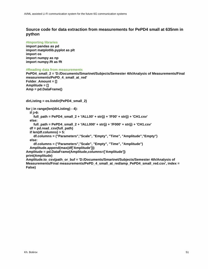
AI/ML assisted Li-Fi communication system for the future 6G communication systems
Kh. Botirov 51
Source code for data extraction from measurements for PePD4 small at 635nm in python #Importing libraries import pandas as pd import matplotlib.pyplot as plt import os import numpy as np import numpy.fft as fft #Reading data from measurements PePD4_small_2 = 'D:/Documents/Smartnet/Subjects/Semester 4th/Analysis of Measurements/Final measurements/PePD_4_small_at_red' Folder_Amount = [] Amplitude = [] Amp = pd.DataFrame() dirListing = os.listdir(PePD4_small_2) for j in range(len(dirListing) - 4): if j>9: full_path = PePD4_small_2 + '/ALL00' + str(j) + '/F00' + str(j) + 'CH1.csv' else: full_path = PePD4_small_2 + '/ALL000' + str(j) + '/F000' + str(j) + 'CH1.csv' df = pd.read_csv(full_path) if len(df.columns) > 5: df.columns = ("Parameters","Scale", "Empty", "Time", "Amplitude","Empty") else: df.columns = ("Parameters","Scale", "Empty", "Time", "Amplitude") Amplitude.append(max(df['Amplitude'])) Amplitude = pd.DataFrame(Amplitude,columns=['Amplitude']) print(Amplitude) Amplitude.to_csv(path_or_buf = 'D:/Documents/Smartnet/Subjects/Semester 4th/Analysis of Measurements/Final measurements/PePD_4_small_at_red/amp_PePD4_small_red.csv', index = False)

AI/ML assisted Li-Fi communication system for the future 6G communication systems
Kh. Botirov 52
ANNEX II
Figure 19. Values of large PePDs bandwidth thought different methods
Figure 20. Values of small PePDs bandwidth thought different methods
Figure 21. PePD4 small Dark Current vs Voltage
137.5
437.5 450487.5
208
382313
397
3673
221
73
0
100
200
300
400
500
600
PePD 2 large atgreen
PePD 2 large at red PePD 3 large atgreen
PePD 3 large at red
Peak Voltage Rise Time FFT
21000 2550030500 36250
1902123648
3102826119
15869 17089
2563422071
0
10000
20000
30000
40000
PePD 3 small atgreen
PePD 3 small atred
PePD 4 small atgreen
PePD 4 small atred
Peak Voltage Rise Time FFT
-5
0
5
10
15
20
25
30
-0.5 0 0.5 1 1.5
Dar
k C
urr
ent,
mA
/cm
^2
Voltage, mV

AI/ML assisted Li-Fi communication system for the future 6G communication systems
Kh. Botirov 53
REFERENCES
[1] Kaushal, H. and Kaddoum, G., 2017. Optical Communication in Space: Challenges and Mitigation Techniques. IEEE Communications Surveys & Tutorials, 19(1), pp.57-96.
[2] Haas, H., 2018. Li-Fi is a paradigm-shifting 5G technology. Reviews in Physics, 3, pp.26-31. [3] Rahman, M., Bakibillah, A., Parthiban, R. and Bakaul, M., 2020. Review of advanced techniques for
multi‐gigabit visible light communication. IET Optoelectronics, 14(6), pp.359-373. [4] D. Hochfelder, “Alexander graham bell,” Encylopedia Britannica, 2015. [5] D. L. Hutt, K. J. Snell, and P. A. Belanger, “Alexander graham bell’s photophone,” Tech. Report: Optic
& Photonics News, 1993. [6] Rajagopal, S., Roberts, R. and Lim, S., 2012. IEEE 802.15.7 visible light communication: modulation
schemes and dimming support. IEEE Communications Magazine, 50(3), pp.72-82. [7] E. Sarbazi, M. Uysal, M. Abdallah, and K. Qaraqe, “Ray tracing based channel modeling for visible
light communications,” in Proc. 22nd Signal Process. Commun. Appl. Conf., Apr. 2014, pp. 702–705. [8] A. Farid and S. Hranilovic, “Capacity bounds for wireless optical intensity channels with Gaussian
noise,” IEEE Trans. Inf. Theory, vol. 56, no. 12, pp. 6066–6077, Dec. 2010. [9] IEEE Std. 802.15.7-2011, IEEE Standard for Local and Metropolitan Area Networks, Part 15.7: Short-
Range Wireless Optical Communication Using Visible Light, IEEE Std., 2011.
[10] R. Mesleh, H. Elgala, and H. Haas, “Optical spatial modulation,” IEEE/OSA J. Opt. Commun. Netw.,
vol. 3, no. 3, pp. 234–244, Mar. 2011.
[11] F.-M. Wu, C.-T. Lin, C.-C. Wei, C.-W. Chen, H.-T. Huang, and C.-H. Ho, “1.1-Gb/s white-LED-based
visible light communication Employing carrier-less amplitude and phase modulation,” IEEE Photon.
Technol. Lett., vol. 24, no. 19, pp. 1730–1732, Oct. 2012.
[12] T. Komine, S. Haruyama, and M. Nakagawa, “Performance evaluation of narrowband OFDM on
integrated system of power line communication and visible light wireless communication,” in Proc. Int.
Symp. Wireless Pervasive Comput., Jan. 2006, doi: 10.1109/ISWPC.2006.1613633.
[13] J. Armstrong and A. Lowery, “Power efficient optical OFDM,” Electronics Letters, vol. 42, no. 6, pp.
370–372, 2006.
[14] Miao, J. and Zhang, F., 2019. Recent progress on highly sensitive perovskite photodetectors. Journal
of Materials Chemistry C, 7(7), pp.1741-1791.
[15] Ahmadi, M., Wu, T. and Hu, B., 2017. A Review on Organic–Inorganic Halide Perovskite
Photodetectors: Device Engineering and Fundamental Physics. Advanced Materials, 29(41),
p.1605242.
[16] Li, C., Wang, H., Wang, F., Li, T., Xu, M., Wang, H., Wang, Z., Zhan, X., Hu, W. and Shen, L., 2020.
Ultrafast and broadband photodetectors based on a perovskite/organic bulk heterojunction for large-
dynamic-range imaging. Light: Science & Applications, 9(1).
[17] Y. Wang, X. Li, J. Song, L. Xiao, H. Zeng and H. Sun, All-inorganic colloidal perovskite quantum dots:
a new class of lasing materials with favorable characteristics, Adv. Mater., 2015, 27(44), 7101–7108.
[18] S. H. Turren-Cruz, A. Hagfeldt and M. Saliba, Methylammonium-free, high-performance, and stable
perovskite solar cells on a planar architecture, Science, 2018, 362(6413), 449–453.
X. Zhao and N. G. Park, Stability issues on perovskite solar cells, Photonics, 2015, 2, 1139–1151.
[19] K. Domanski, J. P. Correa-Baena, N. Mine, M. K. Nazeeruddin, A. Abate, M. Saliba, W. Tress, A.
Hagfeldt and M. Grätzel, Not all that glitters is gold: metal-migration-induced degradation in perovskite
solar cells, ACS Nano, 2016, 10(6), 6306–6314.
[20] C. L. Tsai, Y. C. Lu and S. H. Chang, Enhancement of photocurrent extraction and electron injection
in dualfunctional CH3NH3PbBr3 perovskite-based optoelectronic devices via interfacial engineering,
Nanotechnology, 2018, 29(27), 275704.
[21] G. Namkoong, A. A. Mamun and T. T. Ava, Impact of PCBM/C60 electron transfer layer on charge
transports on ordered and disordered perovskite phases and hysteresis free perovskite solar cells,
Org. Electron., 2018, 56, 163–169.
[22] C. Li, Z. Zang, W. Chen, Z. Hu, X. Tang, W. Hu, K. Sun, X. Liu and W. Chen, Highly pure green light
emission of perovskite CsPbBr3 quantum dots and their application for green light-emitting diodes,
Opt. Express, 2016, 24(13), 15071–15078.
[23] J. Troughton, K. Hooper and T. M. Watson, Humidity resistant fabrication of CH3NH3PbI3 perovskite
solar cells and modules, Nano Energy, 2017, 39, 60–68.

AI/ML assisted Li-Fi communication system for the future 6G communication systems
Kh. Botirov 54
[24] W. Ming, D. Yang, T. Li, L. Zhang and M. H. Du, Formation and diffusion of metal impurities in
perovskite solar cell material CH3NH3PbI3: implications on solar cell degradation and choice of
electrode, Adv. Sci., 2018, 5(2), 1700662.
[25] H. Huang, F. Zhao, L. Liu, F. Zhang, X. G. Wu, L. Shi, B. Zo, Q. Pei and H. Zhong, Emulsion synthesis
of size-tunable CH3NH3PbBr3 quantum dots: an alternative route toward efficient light-emitting diodes,
ACS Appl. Mater. Interfaces, 2015, 7(51), 28128–28133.
[26] Tsai, C., Lu, Y., Chiang, S., Yu, C., Cheng, H., Hsu, C., Chiu, K. and Chang, S., 2020. Bright and fast-
response perovskite light-emitting diodes with an ICBA:modified-C60 nanocomposite electrical
confinement layer. Nanoscale, 12(6), pp.4061-4068.
[27] K. Y. Chiu, S. H. Chang, W. C. Huang, H. M. Cheng, H. Shaw, S. C. Yeh, C. T. Chen, Y. O. Su, S. H.
Chen and C. G. Wu, Functional graded fullerene derivatives for improving the fill factor and device
stability of invertedtype perovskite solar cells, Nanotechnology, 2018, 29(30), 305701.
[28] N. Chi, J. Jia, F. Hu, Y. Zhao and P. Zou, "Challenges and prospects of machine learning in visible
light communication," in Journal of Communications and Information Networks, vol. 5, no. 3, pp. 302-
309, Sept. 2020, doi: 10.23919/JCIN.2020.9200893.
[29] BISHOP C M. Pattern recognition and machine learning[M]. Berlin: Springer, 2006.
[30] WANG Y, TAO L, HUANG X, et al. 8-Gb/s RGBY LED-based WDM VLC system employing high-order
CAP modulation and hybrid post equalizer[J]. IEEE Photonics Journal, 2015, 7(6): 1-7.
[31] KHAN F N, LU C, LAU A P T. Machine learning methods for optical communication systems[C]//Signal
Processing in Photonic Communications. Washington D. C.: Optical Society of America, 2017: SpW2F-
3.
[32] R. Bian, I. Tavakkolnia, and H. Haas, “15.73Gb/s visible light communication with off-the-shelf LEDs,”
J. Lightw. Technol., vol.37, no.10, pp. 2418-2424, May 2019.
[33] Cisco, “Cisco Annual Internet Report (2018-2023) White Paper”, 2020.
[34] “LOI n 2015-136 du 9 f´evrier 2015 (“Loi Abeille”)”, JORF, no. 0034, p.2346, Feb 2015.
[35] Bao, C., Xu, W., Yang, J., Bai, S., Teng, P., Yang, Y., Wang, J., Zhao, N., Zhang, W., Huang, W. and
Gao, F., 2020. Bidirectional optical signal transmission between two identical devices using perovskite
diodes. Nature Electronics, 3(3), pp.156-164.
[36] Clifford, J. P. et al. Fast, sensitive and spectrally tuneable colloidal-quantumdot photodetectors. Nat.
Nanotechnol. 4, 40–44 (2009).
[37] Tan, Z. K. et al. Bright light-emitting diodes based on organometal halide perovskite. Nat. Nanotechnol. 9, 687–692 (2014).
[38] Sutherland, B. R. & Sargent, E. H. Perovskite photonic sources. Nat. Photonics 10, 295–302 (2016). [39] Dou, L. et al. Solution-processed hybrid perovskite photodetectors with high detectivity. Nat. Commun.
5, 5404 (2014). [40] Feng, J. et al. Single-crystalline layered metal–halide perovskite nanowires for ultrasensitive
photodetectors. Nat. Electron. 1, 404–410 (2018). [41] Shen, L. et al. A self‐powered, sub‐nanosecond‐response solution‐processed hybrid perovskite
photodetector for time‐resolved photoluminescence-lifetime detection. Adv. Mater. 28, 10794–10800 (2016).
[42] Bao, C. et al. Low-noise and large-linear-dynamic-range photodetectors based on hybrid-perovskite thin-single-crystals. Adv. Mater. 29, 1703209 (2017).
[43] Chiba, T. et al. Anion-exchange red perovskite quantum dots with ammonium iodine salts for highly efficient light-emitting devices. Nat. Photonics 12, 681–687 (2018).
[44] Zhao, B. et al. High-efficiency perovskite–polymer bulk heterostructure light-emitting diodes. Nat. Photonics 12, 783–789 (2018).
[45] Cao, Y. et al. Perovskite light-emitting diodes based on spontaneously formed submicrometre-scale structures. Nature 562, 249–253 (2018).
[46] Lin, K. et al. Perovskite light-emitting diodes with external quantum efficiency exceeding 20 per cent. Nature 562, 245–248 (2018).
[47] Xu, W. et al. Rational molecular passivation for high-performance perovskite light-emitting diodes. Nat. Photonics 13, 418–424 (2019).
[48] Liao, C., Chang, Y., Ho, C. and Wu, M., 2013. High-Speed GaN-Based Blue Light-Emitting Diodes With Gallium-Doped ZnO Current Spreading Layer. IEEE Electron Device Letters, 34(5), pp.611-613.
[49] Liao, C. L., Ho, C. L., Chang, Y. F., Wu, C. H. & Wu, M. C. High-speed light-emitting diodes emitting at 500 nm with 463-Mhz modulation bandwidth. IEEE Electron Device Lett. 35, 563–565 (2014).

AI/ML assisted Li-Fi communication system for the future 6G communication systems
Kh. Botirov 55
[50] Kim, J. S., Kajii, H. & Ohmori, Y. Characteristics of optical response in red organic light-emitting diodes using two dopant system for application to the optical link devices. Thin Solid Films 499, 343–348 (2006).
[51] 2017. PDA25K(-EC) GaP Switchable Gain Detector. 1st ed. ThorLabs. [52] 2021. PLT5 510 Metal Can® TO56 Green Laser Diode in TO56 Package. OSRAM Opto
Semiconductors GmbH. [53] 2019. 635nm Red Single Mode Laser Diode RLD63NPC5. ROHM Co., Ltd. [54] Qiu, Y., Chen, H. and Meng, W., 2016. Channel modeling for visible light communications-a
survey. Wireless Communications and Mobile Computing, 16(14), pp.2016-2034. [55] N. Fernando, Y. Hong and E. Viterbo, "Flip-OFDM for optical wireless communications," 2011 IEEE
Information Theory Workshop, 2011, pp. 5-9, doi: 10.1109/ITW.2011.6089566. [56] S. Dörner, S. Cammerer, J. Hoydis, and S. ten Brink, ``Deep learning based communication over the
air,'' IEEE J. Sel. Topics Signal Process., vol. 12, no. 1, pp. 132_143, Feb. 2018. [57] T. Wang, C.-K. Wen, H. Wang, F. Gao, T. Jiang, and S. Jin, ``Deep learning for wireless physical layer:
Opportunities and challenges,'' China Commun., vol. 14, no. 11, pp. 92_111, 2017.