aim & thurlby thandar instruments - farnell … · internal/external modulation, am, fm, pm,...
TRANSCRIPT

Internal/external modulation, AM, FM, PM, PWM, Sum, FSK, BPSK
AIM & THURLBY THANDAR INSTRUMENTS
Advanced Function/Arbitrary/Pulse Generators - Single or Dual Channel
TG2511A | TG2512A | TG5011A | TG5012A
Arbitrary waveforms of up to 128K points at up to 125MS/s
Up to 50MHz sine and square, 14 digits or 1µHz resolution
True pulse generator with variable delay and variable rise/fall
Programmable via USB, GPIB and LXI compliant LAN interfaces
aimtti.comaimtti.co.uk | aimtti.us
Features at a glance
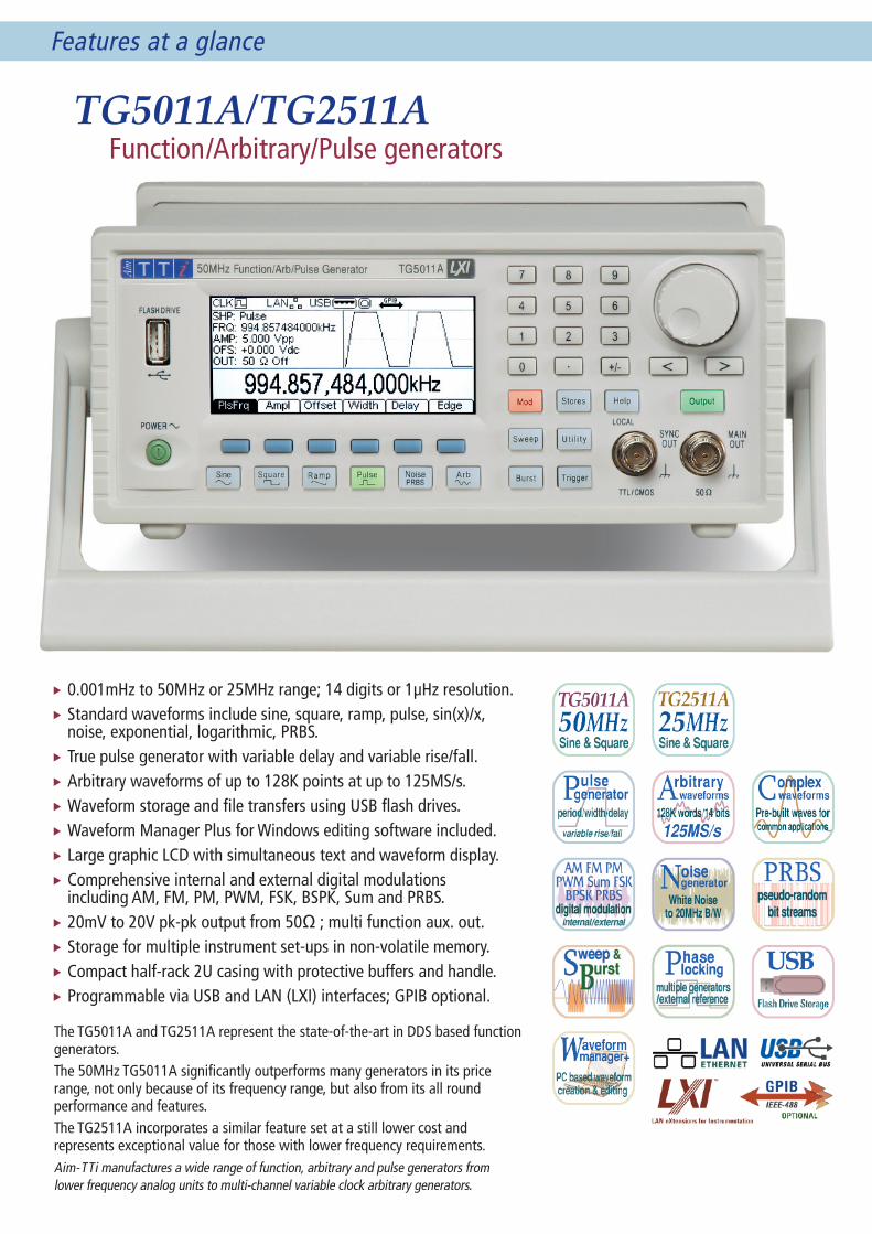
TG5011A/TG2511A Function/Arbitrary/Pulse generators
The TG5011A and TG2511A represent the state-of-the-art in DDS based function generators.The 50MHz TG5011A significantly outperforms many generators in its price range, not only because of its frequency range, but also from its all round performance and features.The TG2511A incorporates a similar feature set at a still lower cost and represents exceptional value for those with lower frequency requirements.Aim-TTi manufactures a wide range of function, arbitrary and pulse generators from lower frequency analog units to multi-channel variable clock arbitrary generators.
0.001mHz to 50MHz or 25MHz range; 14 digits or 1µHz resolution.Standard waveforms include sine, square, ramp, pulse, sin(x)/x, noise, exponential, logarithmic, PRBS.True pulse generator with variable delay and variable rise/fall.Arbitrary waveforms of up to 128K points at up to 125MS/s.Waveform storage and file transfers using USB flash drives.Waveform Manager Plus for Windows editing software included.Large graphic LCD with simultaneous text and waveform display.Comprehensive internal and external digital modulations including AM, FM, PM, PWM, FSK, BSPK, Sum and PRBS.20mV to 20V pk-pk output from 50Ω ; multi function aux. out.Storage for multiple instrument set-ups in non-volatile memory.Compact half-rack 2U casing with protective buffers and handle.Programmable via USB and LAN (LXI) interfaces; GPIB optional.

Features at a glance
TG5012A/TG2512A 2 Channel Function/Arbitrary/Pulse generators
The TG5012A and TG2512A are two channel versions of the TG5011A/2511A and have identical features augmented by multi-channel capabilities including coupling for frequency and/or level, full tracking, and defined phase offset.The channels can also be used as completely independent generators and they represent excellent value for money when compared with buying two generators..
Two channels - independent or linked with coupled/tracking modes.Selectable coupling of frequency (equal or offset), amplitude/dc offset.Inter-channel phase offset of -360o to +360o with 0.1o resolution.0.001mHz to 50MHz or 25MHz range; 14 digits or 1µHz resolution.Standard waveforms include sine, square, ramp, pulse, sin(x)/x, noise, exponential, logarithmic, PRBS.True pulse generator with variable delay and variable rise/fall.Arbitrary waveforms of up to 128K points at up to 125MS/s.Waveform storage and file transfers using USB flash drives.Waveform Manager Plus for Windows editing software included.Large graphic LCD with simultaneous text and waveform display.Comprehensive internal and external digital modulations including AM, FM, PM, PWM, FSK, BSPK, Sum and PRBS.20mV to 20V pk-pk output from 50Ω ; multi function aux. out.Storage for multiple instrument set-ups in non-volatile memory.Compact half-rack 2U casing with protective buffers and handle.Programmable via USB and LAN (LXI) interfaces; GPIB optional.
See Page 6 for more details concerning two channel models.

Features in detail
Higher Waveform FrequenciesThe TG501xA out-performs other generators in its price range by offering both sine and square waves up to 50MHz. The lower cost TG251xA operates to 25MHz.
Exceptional frequency precisionThe frequency of these waveforms can be set with up to 14 digits or one micro hertz of resolution.The DDS based frequency generation system uses a TCXO timebase oscillator with a stability of 1ppm.
Waveform qualityThe TG501xA and TG251xA generate high purity sine waves with low harmonic distortion and low phase noise. Square waves have a rise time of below 8ns (13ns on TG251xA) and low overshoot. Variable symmetry can be used up to 25MHz.
Triangle and rampHigh quality triangle and variable symmetry ramp waveforms are available up to 500kHz (TG501xA) or 250kHz (TG251xA).These waveforms are also available at higher frequencies via the arbitrary function but without symmetry adjustment and with reduced waveform quality as the frequency increases.
VLF generationThe high resolution of the DDS system means that very low frequencies can be set. For example, a frequency of around 1mHz could be set with a resolution of 0.1% and a stability of 1ppm.
Full Pulse Generator capabilitiesBoth models incorporate a pulse generator mode which provides wide range pulse width and delay independent of period. Rise and fall times (edge speeds) are also fully variable.
Wide-range repetition rateOn the TG501xA, the pulse period can be set between 80ns and 2000 secs. (0.5mHz to 12.5MHz) with a resolution of 14 digits or 1µHz. On the TG251xA, the minimum pulse period is 160ns (6.25MHz).
Fully variable pulse width and delayPulse width and pulse delay can be independently set to a resolution of 10ns. Minimum pulse width is 20ns and duty cycles can be as low as one in two billion.
Note that display screens on this page are shown at around 80% of actual size.
Independently variable rise and fallThe generators offer very fast edge speeds of better than 8ns on the TG501xA or 13ns on the TG251xA, but the edges can be slowed down to simulate slower pulses. Rise and fall times are independently variable in the range 5ns to 40us (10ns to 40µs on the TG251xA), or can be linked so that both edge speeds are the same.
Trigger, burst and gate As with all other waveforms, pulses can be triggered from an external trigger input (or a manual trigger, the internal trigger generator or a Bus command).Burst mode creates a burst of between one and a million pulses in response to each active edge of the trigger.Gated cause pulses to be generated only when the gate signal is true. The gate source can be external or internal exactly as the trigger signal.
Arbitrary WaveformsBoth generators offer DDS generated arbitrary waveforms capability. A number of standard waveforms are included, and up to four user defined arbitrary waveforms can be stored in the instrument at any one time.
14 bits, 128k words, 125MS/sWaveforms have a vertical resolution of 14 bits (16,384 amplitude levels). Waveforms can be created using between 2 and 131,072 points (128k).The sampling rate is 125MHz and DDS techniques are used to provide any repetition rate between 1µHz and 10MHz (TG501xA) or 6MHz (TG251xA) with up to 14 digits of frequency resolution.
Internal and external waveform storageUp to four user defined waveforms totalling up to 256k words can be stored within the permanent internal memory of the instrument.However, a front mounted USB port enables external Flash memory storage of up to 1000 waveforms of any size.This memory stick also provides a quick and convenient method for transferring waveform files to and from a PC. It can also be used for storing instrument set-ups.
Pre-built complex waveformsCommonly used complex waveforms are provided both built-in to the instrument and for loading into the user defined waveform space.These include sin(x)/x, exponential rise and fall,
logarithmic rise and fall, gaussian, lorentz, haversine and cardiac waveforms.
Waveform creation & editingArbitrary waveforms can be created and edited using the simple tools built into the instrument. However, complex waveforms require an external PC based editor.Both instruments are supplied with Waveform Manager Plus for Windows® which provides the most comprehensive set of waveform tools available including a mathematical expression editor, freehand drawing, waveform libraries, and import of waveforms using the Clip Board.More information is provided on Page 7 of this brochure.
Standard, Pulse and Arbitrary Waveforms

Features in detail
USB Flash Drive InterfaceBoth instruments incorporate a front mounted USB socket for connection of flash memory disk drives which can store up to 1,000 waveforms and 1,000 setups.
Unlimited Waveform StorageThese drives can be used both to store waveforms permanently and to transfer waveforms from or to a PC. Arbitrary waveform storage within the instrument is limited to four waveforms. Each flash drive can store up to 1000 waveforms which can be accessed using the instruments file handling utilities.
Storage of Instrument Set-upsUp to nine complete set-ups of the instrument can be stored within its own non-volatile memory. Up to 1000 further set-ups can be stored on each flash drive.
PRBS WaveformsA PRBS (Pseudo-Random Bit Sequence) is a binary waveform with a sequence that is almost impossible to predict. PRBS waveforms are used within secure communications systems.
A PRBS is generated by a linear-feedback shift register with taps that generate a feedback signal via an exclusive-OR gate. The number of stages determines the sequence length (2N-1) whilst the clock frequency determines the bit rate. The stage length can be set to 7, 9, 11, 15, 20, or 23, resulting in sequence lengths from 127 to 8,388,607 bits at rates between 1µbps to 50Mbps. Edges have variable rise and fall as per pulse waveforms. The PRBS waveform can be used as both a carrier and a modulator.
Digital Modulation, Internal & ExternalThe generators offer a comprehensive set of digitally based modulations.The internal modulation source can use any of the standard or arbitrary waveforms currently within
the generator (including noise) thus removing the need for an external modulation source. A modulating frequency between 1µHz and 1MHz can be specified.An external modulation input enables any external waveform source to be used when required. The external bandwidth is DC to 20kHz.
AM, FM and PMSine, square, ramp or arbitrary waveforms can be modulated using amplitude, frequency or phase modulation.Amplitude depth is variable from 0.0% to 120.0%, frequency deviation from zero to Fmax/2, and phase deviation from -360.0 to +360.0 degrees.
PWMPulse width modulation is available for the pulse function using any standard or arbitrary waveform including noise. Pulse width deviation is variable between 0% and 100%.
SumSum modulation adds the modulating waveform to the carrier. It can be used with Sine, Ramp and Arbitrary carrier waveforms along with any modulating waveform.
FSK and BPSKFrequency shift keying between any two frequencies is available for sine, square, ramp or arbitrary waveforms using the internal trigger generator or an external trigger signal.The internal trigger generator is variable between 2mHz and 1MHz with nine digit resolution.BPSK (Binary Phase Shift Keying) is similar to FSK but it is the carrier’s phase, rather than its frequency, that switches between two values. It has advantages in terms of bandwidth used.
PRBSA PRBS waveform can be used as a modulating waveform at bit rates between 1ubps to 1Mbps.
Sweep and BurstSweep, Burst and Gated modes of operation are available using either an external trigger signal or the internal trigger generator.
Wide range Frequency SweepPhase continuous sweep is available for all standard and arbitrary waveforms except for pulse. The sweep range is from 1µHz through to the maximum for the chosen carrier waveform. Start and stop frequencies can be set independently.The sweep can be linear or logarithmic, triggered or continuous with a period between 1ms and 500s. The sweep trigger can be manual or internal from the trigger generator or external from the trigger socket or from a remote interface command.A marker is provided that outputs an edge synchronous with any frequency point within the sweep.
Triggered BurstIn Burst mode, each active edge of the trigger will produce one burst of the waveform.The number of cycles in a burst can be set between 1 and 16,777,215 (or infinite). The burst starts and ends at a waveform phase angle settable between -360.0 to +360.0 degrees.
Trigger signalThe trigger signal can be manual from the front panel key, internal from the internal trigger generator, external from the trigger-in socket, or remote via a bus command.The trigger-in socket has a nominal TTL threshold and can be set to +ve edge or -ve edge triggering. The minimum trigger pulse width is 50ns.The internal trigger generator is variable between 2mHz and 1MHz with 9 digit resolution.
Storage, Modulations, Sweep & Burst
Features in detail
GatedIn Gated mode the waveform runs only when the gate signal is true. The start point of the waveform is settable from -360.0 to +360.0 degrees and a the last cycle is completed after the gate signal goes false.All of the options available for triggering are available for gating. The trigger-in socket can be set as high or low for true.
Noise GenerationBoth models can generate gaussian white noise to a -3dB bandwidth of 20MHz. The noise generation algorithm achieves a high crest factor (peak to rms ratio) of 5.27.
Adding Noise to a waveformNoise can be added to any waveform except pulse. The amount of noise added can be specified as 0% to 50% of the amplitude of the carrier waveform.
Modulating with NoiseNoise can be used as the modulating waveform for AM, FM, PM or PWM modulations using any of the carrier waveforms allowable for that modulation type.
Locking to Other SourcesBoth the models include external reference and phase locking as standard, unlike some competitor products for which they are an expensive option.
External Frequency ReferenceThe generators use a high quality TCXO crystal as the internal frequency reference providing 1ppm accuracy and stability. If a higher accuracy or stability is required, an external 10MHz reference signal (from an off-air standard for example) can be applied to the Ref. Clock input.
Phase Locking Two Generators (or more)Two generators can be synchronised to provide outputs at the same frequency (or at harmonics) and with a phase difference.The amplitude and phase of these outputs can also be modulated providing the capability to perform QAM and QPSK respectively.Any waveform other than pulse can be used, and the phase difference is adjustable between -360.0 and +360.0 to a resolution of 0.1 degrees. Skew is better than 5ns.It is also possible to synchronise more than two generators but the resulting precision is not specified.N.B. In the case of two channel generators, when phase synchronising is performed the two channels of each generator are also synchronised providing four synchronous waveforms.
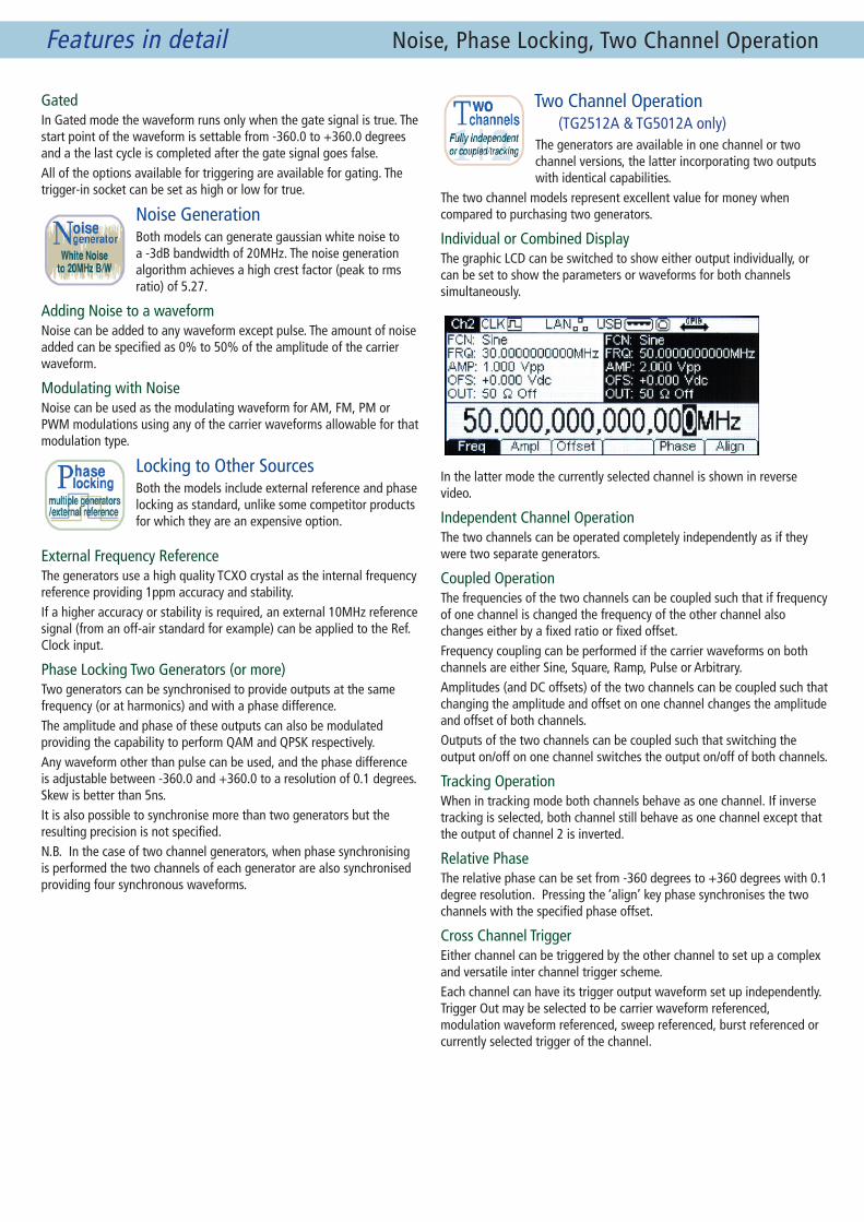
Two Channel Operation (TG2512A & TG5012A only)The generators are available in one channel or two channel versions, the latter incorporating two outputs with identical capabilities.
The two channel models represent excellent value for money when compared to purchasing two generators.
Individual or Combined DisplayThe graphic LCD can be switched to show either output individually, or can be set to show the parameters or waveforms for both channels simultaneously.
In the latter mode the currently selected channel is shown in reverse video.
Independent Channel OperationThe two channels can be operated completely independently as if they were two separate generators.
Coupled OperationThe frequencies of the two channels can be coupled such that if frequency of one channel is changed the frequency of the other channel also changes either by a fixed ratio or fixed offset. Frequency coupling can be performed if the carrier waveforms on both channels are either Sine, Square, Ramp, Pulse or Arbitrary.Amplitudes (and DC offsets) of the two channels can be coupled such that changing the amplitude and offset on one channel changes the amplitude and offset of both channels.Outputs of the two channels can be coupled such that switching the output on/off on one channel switches the output on/off of both channels.
Tracking OperationWhen in tracking mode both channels behave as one channel. If inverse tracking is selected, both channel still behave as one channel except that the output of channel 2 is inverted.
Relative PhaseThe relative phase can be set from -360 degrees to +360 degrees with 0.1 degree resolution. Pressing the ‘align’ key phase synchronises the two channels with the specified phase offset.
Cross Channel TriggerEither channel can be triggered by the other channel to set up a complex and versatile inter channel trigger scheme.Each channel can have its trigger output waveform set up independently. Trigger Out may be selected to be carrier waveform referenced, modulation waveform referenced, sweep referenced, burst referenced or currently selected trigger of the channel.
Noise, Phase Locking, Two Channel Operation

Features in detail
Full Remote ControlAll functions of the generators can be controlled from the digital interfaces. Arbitrary waveform data can also be loaded using these interfaces.
An IVI driver for Windows is supplied. This provides support for common applications such as LabView*, LabWindows* and HP-VEE*.
The LAN interface uses a standard 10/100 base-T Ethernet hardware connection with ICMP and TCP/IP Protocol for connection to a Local Area Network or
direct connection to a single PC.This interface supports LXI and is the most appropriate for larger system use because of its scalable nature.
The LAN interface is compliant with LXI (LAN eXten-sions for Instrumentation). LXI is the next-generation, LAN-based modular architecture standard for automated test systems
managed by the LXI Consortium, and is expected to become the successor to GPIB in many systems.
USB provides a simple and convenient means of connection to a PC and is particularly appropriate for small system use. USB has effectively replaced RS232 in many applications.
The interface uses a standard USB 2.0 hardware connection and is implemented as virtual-COM port. A Windows* USB driver is provided.As well as the rear mounted USB device interface connector, a front mounted USB Host interface connector allows USB Flash memory to be connected.
An optional GPIB (IEEE-488) interface is available. When fitted, the instruments retain the USB and LAN interfaces giving them even greater flexibility.
* LabView and LabWindows are trademarks of National Instruments. HPVEE (now Agilent VEE) is a trademark of Agilent Technologies.
* USB interface is supported for Windows 2000, XP, Vista and Windows 7 and 8. Windows is a trademark of Microsoft Inc.
High Waveform QualityThe high waveform quality with its low aberrations is available over a wide amplitude range of 20mV to 20V pk-pk emf (10mV to 10V into 50 W).
DC offset is provided independently of waveform attenuation so, for example, a waveform amplitude of millivolts can be combined with a dc level of volts.
Intelligent Amplitude DisplayAmplitudes can be displayed as peak to peak or as RMS values, with the rms being correctly calculated for the waveform shape. RMS values can alternatively be specified in dBm.If preferred values can be entered in terms of high level and low level instead of amplitude and offset.The amplitudes are shown relative to the selected load impedance which is 50 W (or High-Z) by default, but can be selected as any impedance between 1 W and 10 kW.
Multi-function Sync OutputThe Sync output provides a logic level signal that can perform a number of functions intended for synchronisation with external equipment:
Normal Waveform Sync Modulation Sync Burst Sync Sweep Sync (with sweep marker) Trigger Signal Out Phase Lock (for 2nd generator)The signal type can be selected manually or automatically dependent upon the function in use.
Rear Panel Inputs and OutputsIn addition to the digital bus interfaces, the rear panel carries four I/O sockets:External Modulation Input - for AM, FM, PM and PWM external modulation.Trigger Input - for external triggering of Burst, Gated or Sweep waveforms.Reference Clock Input - for use with an external frequency reference or phase locking of two generators.Reference Clock Output - a buffered version of whichever clock (internal or external) that the generator is using.
Waveform Manager PlusWaveform Manager Plus (version 4) is a Windows* based application for creation, editing and management of arbitrary waveforms using a PC.It incorporates a complete suite of tools for waveform
creation and editing including standard waveforms, mathematical expressions and freehand drawing. Virtually any waveform can be created using combinations of these tools.
Mathematical Expression EditorThe sophisticated mathematical expression editor allows geometric, logarithmic and pulse functions to be combined to create exact representations of complex signals.Different expressions can be used for different sections of a waveform and can be combined with imported waveforms or drawn waveforms where mathematical representation is not possible.
Import of Other WaveformsThe program offers direct import from .csv files, the most commonly used format for graphical description. Additionally a Clipboard import function supports any waveform that can be described by a set of Y-axis data points regardless of their format.Any instrument or waveform generating program that can create a list of Y values can therefore be accommodated. This is a highly flexible method which can be used to create arbitrary generator waveforms from signals captured by instruments such as oscilloscopes and network analysers, or from software such as MathCad.
Remote Interfaces, Outputs/Inputs, Wave Edit

Features in detail
High Resolution LCDThe 3.6” diagonal panel uses 256 x 112 pixels and provides a large amount of simultaneous information.
System connection information is shown on the top line. Below that is a general status screen showing five major parameters. These parameters change depending upon the function being used.Below the status information is the main editing line which shows the parameter currently under control.
Representative Waveform DisplayThe area the to right of the status section shows a representation of the current waveform.This is more than just a fixed display for each waveform, it is calculated from the waveform parameters and gives a live indication when values such as symmetry, rise time or pulse width are changed.Even user defined arbitrary waveforms are shown (subject to the limitations of the display resolution).Modulation waveforms and representations of the modulated carrier are shown simultaneously. Burst count waveforms are also shown graphically.
Soft Key ControlSix soft keys below the display provide access and control of the parameters for each function.All numeric parameters can be set directly from the numeric keypad, or can be changed using the spin wheel.
Period entry can be chosen instead of frequency, and amplitude and offset can be changed to Hi and Lo levels.Frequencies can be entered in any units from uHz to MHz, periods from ns to seconds, and amplitudes in mV or V, rms or pk-pk, or in dBm
The currently selected waveform and major functions are also indicated by illumination of the respective keys.
Mechanical DrawingsBench-top OperationThe generators are highly compact and use a minimum of bench space.
Protective mouldings guard against knock damage and a multi-position stand angles the instrument conveniently as well as providing a carry handle.
Rack MountingFor system applications the generators can be rack mounted.With the protective mouldings and handle removed the size is half rack width by 2U high.
A 2U rack mounting kit is available suitable for one or two instruments.
Display, Control, Bench/Rack Mounting
Rear panel mounts the digital interfaces and the rear I/O connectors. (Note: GPIB interface is an option)

TG5011A, TG2511A, TG5012A, TG2512A - Technical Specifications
Note that specifications apply to 50MHz models (TG5011A and TG5012A) and that specifications for 25MHz models (TG2511A and TG2512A), where different, are in (dark red).
For two channel models (TG5012A and TG2512A) specification apply to each output.
STANDARD WAVEFORMS
SINENote that purity specifications above 25MHz apply only to the TG5011A & TG5012A.Frequency Range: 1µHz to 50MHz (1µHz to 25MHz)Frequency Resolution: 1µHz, 14 digitsOutput Level: 10mVp-p to 10Vp-p into 50 WAmplitude Flatness Relative to 1kHz: <100kHz 0.1dB, <5MHz 0.15dB, <25MHz 0.3dB, <50MHz 0.5dBHarmonic Distortion: ≤ 1 Vp-p ≥ 1Vp-p DC to 20kHz -65dBc -65dBc 20kHz to 100kHz -60dBc -60dBc 100kHz to 1MHz -45dBc -45dBc 1MHz to 25MHz -40dBc -35dBc 25MHz to 50MHz -40dBc -28dBcNon-Harmonic Spurii: <–60dBc to 1MHz, <–60dBc + 6dB/octave 1MHz to 50MHzPhase Noise: -115dBc/Hz, typical (10kHz offset)
SQUAREFrequency Range: 1µHz to 50MHz (1µHz to 25MHz)Resolution: 1µHz, 14 digitsOutput Level: 10mVp-p to 10Vp-p into 50 WRise and Fall Times: <8ns (<13ns)Overshoot: <5%Variable Duty Cycle: 20% to 80% to 20MHz, 0.1% resolution, 40% to 60% to 25 MHz, 0.1% resolution, 50% (fixed) above 25MHzAsymmetry: 1% of period + 5ns (@ 50% duty)Jitter (RMS): 0.5ns + 100 ppm of period
RAMP & TRIANGLEFrequency Range: 1µHz to 1MHz (1µHz to 500kHz)Resolution: 1µHz, 12 digitsOutput Level: 10mVp-p to 10Vp-p into 50 WLinearity Error: <0.1% to 30 kHzVariable Symmetry: 0.0 % to 100.0 %, 0.1% resolution. Single key operation of 50% (Triangle)Note the triangle and sawtooth waveforms are also available from the arbitrary waveform menu enabling repetition rates of up to 10MHz/6MHz. Waveform quality will deteriorate at higher frequencies however.
PULSEFrequency Range: 500 µHz to 12.5MHz (500 µHz to 6.25MHz)Resolution: 1µHz , 14 digitsOutput Level: 10mVp-p to 10Vp-p into 50 WOvershoot: <5%Jitter: 300ps + 0.01% of periodRise/Fall Times: Rise and Fall times can be independently varied or can be varied together simultaneously.Edge Range: <8ns to 40µs (<13ns to 40µs)Edge Resolution: 0.1ns for rise/fall time ≤100ns; 1ns for rise/fall >100ns and ≤2µs; 10ns for rise/fall >2µs and ≤40µs Width Range: 20ns to 2000s (20ns minimum for period ≤40s; 200 ns minimum for period >40s and ≤400s; 2µs minimum for period >400s)Width Resolution: 10ns for period ≤40s; 100ns for period >40s and ≤400s; 1µs for period >400sDelay Range: 0ns to 2000sDelay Resolution: 10ns for period ≤40s; 100ns for period >40s and ≤400s; 1µs for period >400s
PRBS WAVEFORMSSequence Length: 7, 9, 11, 15, 20, or 23 stages (127 to 8,388,607 bit length)Bit Rate: 1µbps to 50Mbps (1µbps to 25Mbps)Rise/Fall Times: Rise/Fall times can be varied (rise time = fall time).Edge Range: <8ns to 40µs (<13ns to 40µs)
ARBITRARY WAVEFORMS
In-built Arbitrary Waveforms Sinc, Exponential Rise, Logarithmic Rise, DC, Positive and Negative Ramps and Square waveforms are built-in and always present. Additional waveforms are supplied on disc (Cardiac, Gaussian, Exponential Fall, Logarithmic Fall).Frequency Range: 1µHz to 10MHz (1µHz to 6MHz)
User defined Arbitrary WaveformsUp to 4 additional or user defined waveforms may be stored in non-volatile memory. Waveforms can be defined by downloading of waveform data via USB memory stick, remote interfaces, or editing via the instrument’s front panel.Waveform Size: 2 points to 131072 points (128k).Memory Size: Up to 4 waveforms of up to 64k points, or 2 waveforms of up to 128k points, (or 2 of 64k points plus 1 of 128k points).External Storage: Up to 1,000 waveforms per USB memory stickVertical Resolution: 14 bitsFrequency Range: 1µHz to 10MHz (1µHz to 6MHz)Resolution: 1µHz , 14 digitsOutput Level: 10mVp-p to 10Vpp into 50 WSampling rate: 125MS/sOutput Filter: Selects between 50MHz Elliptic or 20MHz Bessel filter depending on the waveform.
Arbitrary Waveform Creation and EditingWaveform creation and editing is provided within the generator including point insertion, line drawing and interpolation.
WAVEFORM MANAGER PLUSBoth generators are supplied with Waveform Manager Plus. This Windows* based software provides a sophisticated tool set for the creation, editing and management of arbitrary waveforms. The waveforms can be transferred to the generator either using a USB memory stick, or by the digital interfaces.
NOISEGaussian White Noise can be chosen as a waveform or added to any carrier waveform except pulse, square and noise itself (note however that noise can be added to the square wave available in the arbitrary menu). The amount of noise added can be specified as 0% to 50% of the amplitude of the carrier waveform. Noise can also be used as modulating waveform.Bandwidth (-3dB): 20MHz typical.Crest Factor: 5.27 (Vp/Vrms)Output Level: 10mVp-p to 10Vpp into 50 W
INTERNAL FREQUENCY REFERENCEAgeing Rate: 1ppm first yearTemp. Stability: <1ppm over the specified temperature range
MODULATION
AMCarrier Waveforms: Sine, Square, Ramp, PRBS, ArbModulation Source: Internal/ExternalInternal Modulating Waveforms: Sine, Square, Up Ramp, Down Ramp, Triangle, Noise, DC, Sinc, Exponential Rise, Logarithmic Rise, PRBS and User Defined ArbsInternal Modulating Frequency: 1µHz to 1MHz, 1µHz resolutionAmplitude Depth: 0.0% to 120.0%, 0.1% resolution
FMCarrier Waveforms: Sine, Square, Ramp, PRBS, ArbModulation Source: Internal/ExternalInternal Modulating Waveforms: Sine, Square, Up Ramp, Down Ramp, Triangle, Noise, DC, Sinc, Exponential Rise, Logarithmic Rise, PRBS and User Defined ArbsInternal Modulating Frequency: 1µHz to 1MHz, 1µHz resolutionFrequency Deviation: DC to Fmax/2, 1µHz resolution
PMCarrier Waveforms: Sine, Square, Ramp, PRBS, ArbModulation Source: Internal/ExternalInternal Modulating Waveforms: Sine, Square, Up Ramp, Down Ramp, Triangle, Noise, DC, Sinc, Exponential Rise, Logarithmic Rise, PRBS and User Defined ArbsInternal Modulating Frequency: 1µHz to 1MHz, 1µHz resolutionPhase Deviation: -360.0 to +360.0 degrees, 0.1 degree resolution
PWMCarrier Waveforms: PulseModulation Source: Internal/ExternalInternal Modulating Waveforms: Sine, Square, Up Ramp, Down Ramp, Triangle, Noise, DC, Sinc, Exponential Rise, Logarithmic Rise, PRBS and User Defined ArbsInternal Modulating Frequency: 1µHz to 1MHz, 1µHz resolutionWidth Deviation: 0% to 100% of pulse width, resolution same as per pulse width
SUMCarrier Waveforms: Sine, Ramp, ArbInternal Modulating Waveforms: Sine, Square, Up Ramp, Down Ramp, Triangle, Noise, DC, Sinc, Exponential Rise, Logarithmic Rise, PRBS and User Defined ArbsInternal Modulating Frequency: 1µHz to 1MHz, 1µHz resolutionRatio: 0% to 100%; 0.1% resolution
FSKCarrier Waveforms: Sine, Square, Ramp, PRBS, ArbSource: Internal/External (via TRIG IN)Internal Modulation: 50% duty cycle square (2mHz to 100kHz)
BPSKCarrier Waveforms: Sine, Square, Ramp, PRBS, ArbSource: Internal/External (via TRIG IN)Internal Modulation: 50% duty cycle square (2mHz to 100kHz)
Triggered BurstEach active edge of the trigger signal will produce one burst of the waveform.Carrier Waveforms: Sine, Square, Ramp, PRBS, Arb, PulseMaximum Carrier Frequency: 10MHz (finite cycles), 50MHz (infinite), subject to carrier waveform.Number of Cycles: 1 to 16,777,215 and infinite.Trigger Rep. Rate: 2mHz to 1MHz internal dc to 1MHz external.Trigger Source: Internal from keyboard or trigger generator. External from TRIG IN or remote interface.Start/Stop Phase: -360.0 to +360.0 degrees, 0.1 degree resolution.

Technical Specifications (continued)
GatedWaveform will run while the Gate signal is true and stop while false.Carrier Waveforms: Sine, Square, Ramp, PRBS, Arb, Pulse, NoiseMax. Carrier Freq.: 10 MHz, subject to carrier waveformTrigger Rep. Rate: 2mHz to 1MHz internal, dc to 1MHz external.Gate Signal Source: Internal from keyboard or trigger generator. External from TRIG IN or remote interface.Start/Stop Phase: -360.0 to +360.0 degrees, 0.1 degree resolution, subject to carrier waveform.
SweepFrequency sweep capability is provided for both standard and arbitrary waveforms.Carrier Waveforms: All standard, PRBS and arbitrary except pulse.Sweep Mode: Linear or logarithmic, triggered or continuous.Sweep Direction: Up, down, up/down or down/up.Sweep Range: From 1µHz to 50MHz, (1µHz to 25MHz) subject to carrier waveform. Phase continuous. Independent setting of the start and stop frequency.Sweep Time: 1ms to 500s (6 digit resolution).Marker: Variable during sweep.Trigger Source: The sweep may be free run or triggered from the following sources: Internal from keyboard or trigger generator. Externally from TRIG IN input or remote interface.
Trigger GeneratorInternal source 2mHz to 1MHz square wave adjustable in 1µs steps, 9 digit resolution. Also available for external use from the SYNC OUT socket.
OUTPUTS
Main OutputOutput Impedance: 50 WAmplitude: 20mV to 20Vp-p open circuit (10mV to 10Vp-p into 50 W). Amplitude can be specified open circuit (Hi Z) or into an assumed load of 50W or a specified impedance between 1 W and 10k W in Vpk-pk, Vrms or dBm.Amplitude Accuracy: 2% ±1mV at 1kHz into 50 W.DC Offset Range: ±10V. DC offset plus signal peak limited to ±10V from 50 W.DC Offset Accuracy: Typically 3% ±10mV.Resolution: 3 digits or 1mV for both Amplitude and DC Offset.
Sync OutMultifunction output user definable or automatically selected to be any of the following:Carrier Waveform Sync: The function varies with waveform type as follows:Sine/Ramp/Pulse - A square wave with 50% duty cycle at the waveform frequency.Square - A square wave with same duty cycle as the main output at the waveform frequency.Arbs - A square wave with 50% duty cycle at the waveform frequency. The sync is a TTL high when the first point of the waveform is output. Noise - No sync associated with noise.Modulation Sync: The function varies with modulation type as follows:AM/FM/PM/PWM - A square wave with 50% duty cycle referenced to the internal modulation waveform when modulation source is internal, or a square wave referenced to the carrier waveform when modulation source is external. No sync is associated with noise as the modulation source.FSK - A square wave referenced to the trigger rate. The sync is a TTL high when hop frequency is the output frequency and TTL low when carrier frequency is the output frequency for positive slope and vice versa for negative slope.Burst Sync: A square wave that is a TTL high when the burst begins and a TTL low when burst is completed.Trigger: Selects the current trigger signal. Useful for synchronizing burst or gated signals.Sweep Sync: The function varies with marker selection as follows:Marker Off - A square wave that is a TTL low from the midpoint of the sweep and a TTL high from the end of the sweep. Marker On - A square wave that is a TTL low from the marker frequency and a TTL high from the end of the sweep.Output Signal Level: Logic level nominally 3V.
Ref Clock OutputBuffered version of the 10MHz clock currently in use (internal or external)Output Level: Nominally 3V logic level from 50 W.
INPUTS
Trig InFrequency Range: DC - 1MHz.Signal Range: Threshold nominally TTL level; maximum input ±10V.Minimum Pulse Width: 50nsPolarity: Selectable as high/rising edge or low/falling edge.Input Impedance: 10k W
External Modulation Input (for AM, FM, PM, PWM)Voltage Range: ± 5V full scaleInput Impedance: 5k W typicalBandwidth: DC to 20kHz
Ref Clock InputInput for an external 10MHz reference clockVoltage Range: 1Vpp – 5VppMaximum Voltage: +5VMinimum Voltage: -1V
TWO CHANNEL OPERATION (TG5012A & TG2512A only)The two channels can be operated independently so as to act as entirely separate generators. Alternatively the channels can interact as follows:
Coupled OperationCoupled Frequency: Frequencies can be coupled such that if frequency of one channel is changed the frequency of the other channel also changes either by a fixed ratio or fixed offset. A pulse waveforms can only be frequency coupled to another pulse waveform, however sine, square, ramp or Arb waveforms can be coupled to any other waveform of that group.Coupled Level: -Amplitudes (and DC offsets) of the two channels can be coupled such that changing the amplitude and offset on one channel changes the amplitude and offset of both channels.Coupled On/Off: Coupling can be set such that switching the output on/off on one channel switches the output on/off of both channels.
Tracking OperationWhen in tracking mode both channels behave as one channel. If inverse tracking is selected, both channel still behave as one channel except that the output of channel 2 is inverted.
Relative PhasePressing the ‘align’ key phase synchronises the two channels with the specified phase offset.Phase Range: -360.0 to +360.0 degreesResolution: 0.1 degreeSkew (typical): <1ns
Cross Channel TriggerEither channel can be triggered by the other channel to set up a complex and versatile inter channel trigger scheme.Each channel can have its trigger output waveform set up independently. Trigger Out may be selected to be carrier waveform referenced, modulation waveform referenced, sweep referenced, burst referenced or the currently selected trigger of the channel.
CrosstalkChannel Crosstalk: Typically better than 80dB
Control and DisplayThe control of each channel is selected by the Channel Select key. The display can be assigned either completely to the selected channel, or the upper section can display the main set-up parameters or waveforms for both channels simultaneously.
PHASE SYNC (Phase Synchronising Two Generators)Two generators can be synchronised together to provide outputs at the same frequency (or harmonics) and with a phase difference. The amplitude and phase of these outputs can also be modulated providing the capability to perform QAM and QPSK respectively. In case of 2 channel generators when phase synchronising is performed the two channels of each generator are also synchronised providing four synchronous waveforms.It is also possible to synchronise more than two generators but the precision is not guaranteed.Carrier Waveforms: Sine, Square, Ramp, Pulse, ArbPhase Range: -360.0 to +360.0 degreesResolution: 0.1 degreeAccuracy: < ±5ns
BUS INTERFACESFull digital remote control facilities are available through LAN and USB and optional GPIB interfaces.LAN Interface: Ethernet 100/10base – T hardware connection. LXI Compliance: LXI V1.2, Class C compliant.USB Interface: Standard USB 2.0 hardware connection. Implemented as virtual-COM port.GPIB Interface: Conforming with IEEE-488.1 and IEEE-488.2 (option G only)USB Flash Drive: Front mounted socket for waveform and setup storage/recall.
Driver Software SuppliedIVI Driver: An IVI driver for Windows is supplied. This provides support for common applications such as LabView*, LabWindows*, HPVEE* etc.LV/CVI Driver: Full installation for CVI and LabVIEW instrument drivers.USB Driver: An installation file is supplied calling a standard Windows* USB driver.
* LabView and LabWindows are trademarks of National Instruments. HPVEE (now Agilent VEE) is a trademark of Agilent Technologies. * USB interface is supported for Windows 2000 and above (inc. 64-bit versions) Windows is a trademark of Microsoft.

Designed and built in Europe by:
Thurlby Thandar Instruments Ltd.Glebe Road, Huntingdon, Cambridgeshire. PE29 7DR United Kingdom
Tel: +44 (0)1480 412451 Fax: +44 (0)1480 450409Email: [email protected] Web: www.aimtti.com
Brochure Part No. 82100-1390 Iss. 3
Available from:
Technical Specifications (continued)
GENERAL SPECIFICATIONS
Display and Data EntryDisplay: Type: Black on white backlit graphics display - pixel format: 256 x 112 Data Entry: Keyboard selection of mode, waveform etc.; value entry direct by numeric keys or by rotary control.Stored Settings: Up to 9 complete instrument set-ups may be stored and recalled from non-volatile memory. Up to 1000 set-ups can be stored per USB stick.
AC SupplyAC Input: 110-240VAC ±10% 50/60Hz; 100-120VAC ±10% 400Hz; 60VA max. Installation Category II.
Temperature & EnvironmentalOperating Range: +5ºC to +40ºC, 20% to 80% RHStorage Range: -20ºC to + 60ºCEnvironmental: Indoor use at altitudes up to 2000m, Pollution Degree 2.
Safety & EMCSafety: Complies with EN61010-1EMC: Complies with EN61326
Physical (one channel models)Size: Bench top use: height 97mm (2.62”); width 250mm (9.84”); length 270mm (10.63”). Rack mounted use: height 86.5mm (3.4”); width 213.5mm (8.4”); length 244mm (9.61”); i.e. ½-rack x 2U.Weight: 2.55 kg (5.6 lbs)
Physical (two channel models)Size: Bench top use: height 97mm (2.62”); width 250mm (9.84”); length 295mm (11.62”). Rack mounted use: height 86.5mm (3.4”); width 213.5mm (8.4”); length 269mm (10.59”); i.e. ½-rack x 2U.Weight: 2.7 kg (5.95 lbs)
OPTIONS
Rack Mount (RM200A)19 inch 2U rack mount suitable for one or two generators.
GPIB Interface (Option TG-GPIB)Retro-fittable GPIB (IEEE-488) interface card.
ORDERING INFORMATIONFour versions of the product are available as follows:TG2511A 25MHz 1-Channel Generator.TG5011A 50MHz 1-Channel Generator.TG2512A 25MHz 2-Channel Generator.TG5012A 50MHz 2-Channel Generator.
TG-GPIB Retro-fittable GPIB interface for any model.
Each product is supplied with the following:Printed operating manual in English. PDF operating manuals on disk in English, French, German, Italian and Spanish.IEC mains lead appropriate to the geographic market in which it is sold.Software on disk including: Waveform Manager Plus for Windows (version 4), IVI driver, LabView driver, CVI driver, USB driver, LXI discovery tool, TCP example program.
Specifications apply for the temperature range 18°C to 28°C after 30 minutes warm-up, at maximum output into 50 W unless otherwise stated.Thurlby Thandar Instruments Ltd. operates a policy of continuous development and reserves the right to alter specifications without prior notice.