aim infotech marelli srae-srt ecu release 1 · marelli srae and marelli srt ecus need a software...
TRANSCRIPT

AiM Infotech
Marelli SRAE-SRT ECU
Release 1.02

1
This tutorial explains how to connect Marelli SRAE and Marelli SRT ECUs to AiM devices.
1 Hardware check
All AiM devices have a 120 Ohm CAN termination resistor. Before connecting Marelli CAN bus to any of them check that only two termination resistors work on the CAN bus once the network is completed. With a multimeter check the resistance between CAN High (positive probe) and CAN Low (ground probe).
• If the reading is 120 Ohm: there is one termination resistor on the ECU site, no additional operations are required: connect AiM device to the vehicle CAN bus.
• If the reading is 50-60 Ohm: there are two termination resistors: either AiM termination resistor – located on the wiring – or one of the resistor located on the vehicle CAN bus are to be removed;
• If the reading shows a very high resistance (nearly infinite): no termination resistor is present: add a resistor on the ECU CAN bus and leave the one included in AiM device.
2 Software setup
Marelli SRAE and Marelli SRT ECUs need a software setting through "Magneti Marelli Vision" application to correctly communicate with AiM devices. Run it and follow carefully these instructions.
• Follow the path: File –> Open

2
• "Open File" panel appears –> Select "SRA_XXXXXX" folder –> Select "CFG" folder.
• Select the configuration file to open –> Click "Open".

3
• Follow the path: Map –> Map files (PTA)...
• ReadWrite Map (PTA) File panel appears: click "Dir.."
• Select "PTA" folder –> Select the file to open –> Click "Open"

4
• ReadWrite Map (PTA) File panel appears: click "Edit..."
• PTA Table panel appears: click "FIND"

5
• Fill in "Data Elements" and if the panel re-appears click "No"
It is now necessary to set these parameters:
• Data Acquisition CAN Line (paragraph 1.1)
• Frequencies repartition table (paragraph 1.2)
• Data Elements Table (paragraph 1.3)
2.1 Setup of Data acquisition CAN line
These Marelli ECUs features two CAN Lines; it is therefore necessary to set via software the CAN Line that will be used when connecting AiM devices.
• Double click "Data acquisition CAN line".

6
To change the CAN line set by default – if necessary – follow these steps:
• right click on the cell highlighted in the image here below
• enable "fill" checkbox
• fill in the CAN line to be used (1 or 0)
• click "OK"
• Press "Esc"
2.2 Setup of Frequencies repartition table
To set the data transmission frequencies used by AiM devices follow these instructions.
• Double click "Frequencies repartition table"

7
To properly set this table:
• right click on the cell highlighted in the image here below
• enable "fill" checkbox and fill in the desired frequency (for example 0x64)
• click "OK"
• Press "Esc"
2.3 Setup of Data Elements Table
This table sets ECU channels.
• Double click "Data Elements Table"
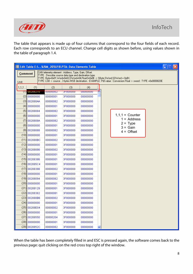
8
The table that appears is made up of four columns that correspond to the four fields of each record. Each row corresponds to an ECU channel. Change cell digits as shown before, using values shown in the table of paragraph 1.4.
When the table has been completely filled in and ESC is pressed again, the software comes back to the previous page: quit clicking on the red cross top right of the window.
9
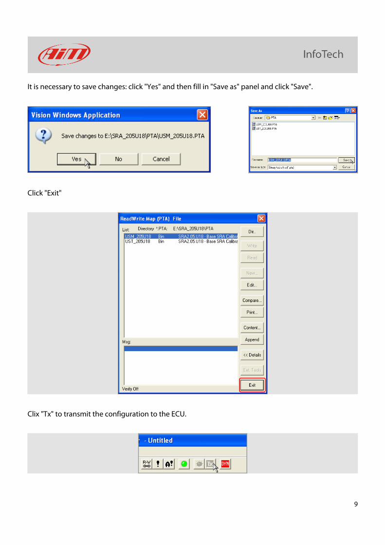
It is necessary to save changes: click "Yes" and then fill in "Save as" panel and click "Save".
Click "Exit"
Clix "Tx" to transmit the configuration to the ECU.
10
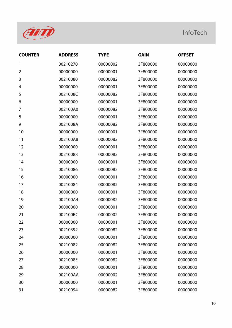
COUNTER ADDRESS TYPE GAIN OFFSET
1 00210270 00000002 3F800000 00000000
2 00000000 00000001 3F800000 00000000
3 00210080 00000082 3F800000 00000000
4 00000000 00000001 3F800000 00000000
5 0021008C 00000082 3F800000 00000000
6 00000000 00000001 3F800000 00000000
7 002100A0 00000082 3F800000 00000000
8 00000000 00000001 3F800000 00000000
9 0021008A 00000082 3F800000 00000000
10 00000000 00000001 3F800000 00000000
11 002100A8 00000082 3F800000 00000000
12 00000000 00000001 3F800000 00000000
13 00210088 00000082 3F800000 00000000
14 00000000 00000001 3F800000 00000000
15 00210086 00000082 3F800000 00000000
16 00000000 00000001 3F800000 00000000
17 00210084 00000082 3F800000 00000000
18 00000000 00000001 3F800000 00000000
19 002100A4 00000082 3F800000 00000000
20 00000000 00000001 3F800000 00000000
21 002100BC 00000002 3F800000 00000000
22 00000000 00000001 3F800000 00000000
23 00210392 00000082 3F800000 00000000
24 00000000 00000001 3F800000 00000000
25 00210082 00000082 3F800000 00000000
26 00000000 00000001 3F800000 00000000
27 0021008E 00000082 3F800000 00000000
28 00000000 00000001 3F800000 00000000
29 002100AA 00000002 3F800000 00000000
30 00000000 00000001 3F800000 00000000
31 00210094 00000082 3F800000 00000000

11
32 00000000 00000001 3F800000 00000000
33 002100B4 00000002 3F800000 00000000
34 00000000 00000001 3F800000 00000000
35 002100BA 00000002 3F800000 00000000
36 00000000 00000001 3F800000 00000000
37 00210E06 00000002 3F800000 00000000
38 00000000 00000001 3F800000 00000000
39 002100A6 00000082 3F800000 00000000
40 00000000 00000001 3F800000 00000000
41 00210D25 00000001 3F800000 00000000
42 00210D26 00000001 3F800000 00000000
43 00210D17 00000001 3F800000 00000000
44 00210D18 00000001 3F800000 00000000
45 00210846 00000001 3F800000 00000000
46 00210845 00000001 3F800000 00000000
47 0021083D 00000001 3F800000 00000000
48 00210130 00000001 3F800000 00000000
49 00210385 00000001 3F800000 00000000
50 00210383 00000001 3F800000 00000000
51 00210381 00000001 3F800000 00000000
52 002105B7 00000001 3F800000 00000000
53 002105B8 00000001 3F800000 00000000
54 002105B6 00000001 3F800000 00000000
55 002105B5 00000001 3F800000 00000000
56 00210386 00000001 3F800000 00000000
57 002100B0 0000820E 3F800000 00000000
58 00000000 00000001 3F800000 00000000
59 00210A18 0000820E 3F800000 00000000
60 00000000 00000001 3F800000 00000000
61 00000000 00000001 3F800000 00000000
62 00000000 00000001 3F800000 00000000
63 00000000 00000001 3F800000 00000000
64 00000000 00000001 3F800000 00000000
12
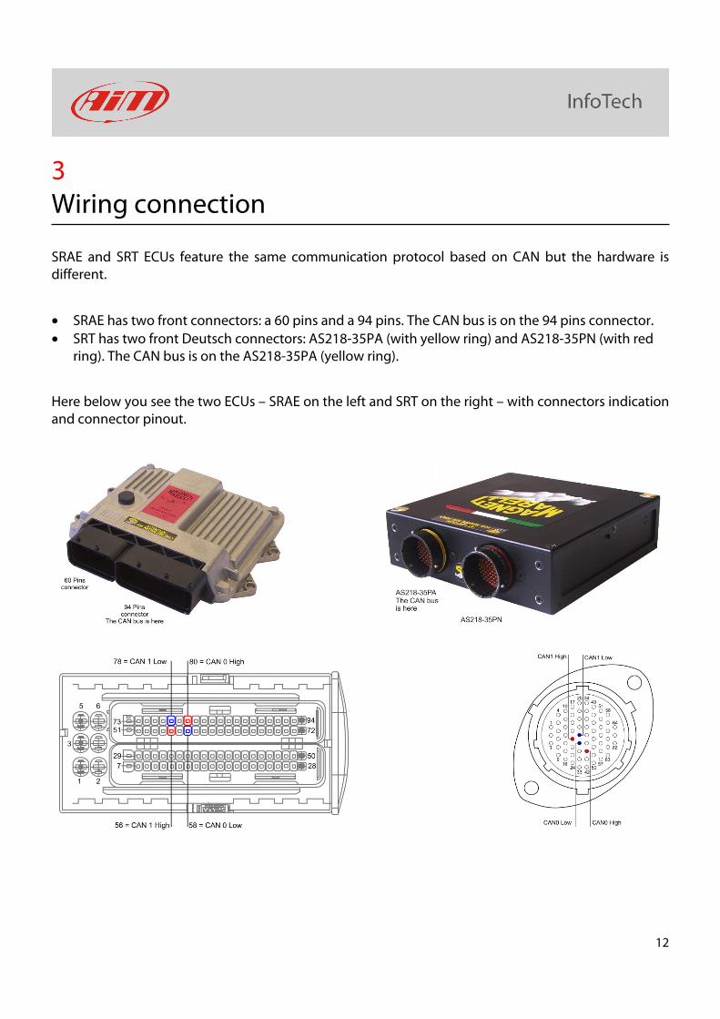
3 Wiring connection
SRAE and SRT ECUs feature the same communication protocol based on CAN but the hardware is different.
• SRAE has two front connectors: a 60 pins and a 94 pins. The CAN bus is on the 94 pins connector.
• SRT has two front Deutsch connectors: AS218-35PA (with yellow ring) and AS218-35PN (with red ring). The CAN bus is on the AS218-35PA (yellow ring).
Here below you see the two ECUs – SRAE on the left and SRT on the right – with connectors indication and connector pinout.

13
Here is connection table
SRAE Connector pin Pin function AiM cable
56 CAN1 High CAN High
78 CAN1 Low CAN Low
80 CAN0 High CAN High
58 CAN0 Low CAN Low
SRT Connector pin Pin function AiM Cable
21 CAN1 High CAN High
29 CAN1 Low CAN Low
40 CAN0 High CAN High
30 CAN0 Low CAN Low
Please note: remember to connect the CAN line you set in software setup (paragraph 1.1).
4 AiM device configuration
Before connecting the ECU to AiM device set this up using AiM Race Studio software. The parameters to select in the device configuration are:
• ECU manufacturer “Marelli”
• ECU Model "SRA_SRAE_SRT"

14
5 Available channels
Channels received by AiM devices connected to "Marelli" "SRA_SRAE_SRT" protocol are:
ID CHANNEL NAME FUNCTION
ECU_1 SRA_RPM RPM
ECU_2 SRA_TPS1 Throttle position sensor bank 1
ECU_3 SRA_PDL1 Active throttle position bank 1
ECU_4 SRA_WTEMP Engine coolant temperature
ECU_5 SRA_OILP Oil pressure
ECU_6 SRA_OILT Oil temperature
ECU_7 SRA_FUELP Fuel pressure
ECU_8 SRA_ATMP Atmospheric pressure
ECU_9 SRA_MAP Manifold air pressure
ECU_10 SRA_AIRT Intake air temperature
ECU_11 SRA_AFR Air fuel ratio
ECU_12 SRA_ADV Ignition advance
ECU_13 SRA_TPS2 Throttle position sensor bank 2
ECU_14 SRA_PDL2 Active throttle position bank 2
ECU_15 SRA_TPS Throttle position sensor
ECU_16 SRA_TCK1 Thermocouple 1
ECU_17 SRA_GEAR Engaged gear
ECU_18 SRA_LAMBDAmV Lambda value in mV
ECU_19 SRA_SPEED Speed
ECU_20 SRA_TFUEL Fuel temperature
ECU_21 SRA_KINGFIL Injection Correction During Up shift
ECU_22 SRA_KTEATFIL Advance Correction F (Up shift)
ECU_23 SRA_PWM1 Duty cycle of Pwm1
ECU_24 SRA_PWM2 Duty cycle of Pwm2
ECU_25 SRA_DPV Derivative pressure

15
ECU_26 SRA_DWG Duty cycle waste gate
ECU_27 SRA_PRLD Rotary switch position for bang start limiter
ECU_28 SRA_ITSP Injection trim switch position
ECU_29 SRA_ASTP Absolute throttle position (default 90%)
ECU_30 SRA_KAWT Coefficient engine cooling temperature multiplier
ECU_31 SRA_KABARO Ign coefficient barometric pressure multiplier (Cranking)
ECU_32 SRA_IKTA Coefficient intake air temperature multiplier (Cranking)
ECU_33 SRA_IKTF Coefficient Fuel temperature multiplier (Cranking)
ECU_34 SRA_IKBARO Inj. coefficient barometric pressure multiplier (Cranking)
ECU_35 SRA_IKADM Injection correction F (Padmission)
ECU_36 SRA_CLAV Advance Correction F (Trimmer Position)
ECU_37 SRA_PDL Active throttle position
ECU_38 SRA_TPSE Throttle position sensor (Encoder)