aiga 095 16 mechanical integrity of syngas outlet systemsasiaiga.org/uploaded_docs/aiga 095_16...
TRANSCRIPT
MECHANICAL INTEGRITY OF SYNGAS OUTLET SYSTEMS
AIGA 095/16
Asia Industrial Gases Association
3 HarbourFront Place, #09-04 HarbourFront Tower 2, Singapore 099254
Tel : +65 6276 0160 • Fax : +65 6274 9379 Internet : http://www.asiaiga.org

Reproduced with permission from the Compressed Gas Association. All rights reserved.
ASIA INDUSTRIAL GASES ASSOCIATION 3 HarbourFront Place, #09-04 HarbourFront Tower 2, Singapore 099254
Tel: +65 62760160 Fax: +65 62749379 Internet: http://www.asiaiga.org
AIGA 095/16
MECHANICAL INTEGRITY OF SYNGAS OUTLET SYSTEMS
As part of a program of harmonization of industry standards, the Asia Industrial Gases Association has pub-lished AIGA 095, Mechanical Integrity of Syngas Outlet Systems, jointly produced by members of the Inter-national Harmonization Council and originally published by the Compressed Gas Association (CGA) as H-12, Mechanical Integrity of Syngas Outlet Systems, This publication is intended as an international harmonized standard for the worldwide use and application of all members of the Asia Industrial Gases Association (AIGA), Compressed Gas Association (CGA), Europe-an Industrial Gases Association (EIGA), and Japan Industrial and Medical Gases Association (JIMGA). Each association’s technical content is identical, except for regional regulatory requirements and minor changes in formatting and spelling.
Disclaimer
All publications of AIGA or bearing AIGA’s name contain information, including Codes of Practice, safety procedures and other technical information that were obtained from sources believed by AIGA to be reliable and/ or based on technical information and experience currently available from members of AIGA and others at the date of the publication. As such, we do not make any representation or warranty nor accept any liability as to the accuracy, completeness or correctness of the information contained in these publications. While AIGA recommends that its members refer to or use its publications, such reference to or use thereof by its members or third par-ties is purely voluntary and not binding. AIGA or its members make no guarantee of the results and assume no liability or responsibility in connection with the reference to or use of information or suggestions contained in AIGA’s publications. AIGA has no control whatsoever as regards, performance or non performance, misinterpretation, proper or improper use of any informa-
tion or suggestions contained in AIGA’s publications by any person or entity (including AIGA members) and AIGA expressly disclaims
any liability in connection thereto.
AIGA’s publications are subject to periodic review and users are cautioned to obtain the latest edition.

AIGA AIGA 095/16
Contents Page
1 Introduction ..................................................................................................................................................... 1
2 Scope and Purpose ........................................................................................................................................ 1
2.1 Scope .................................................................................................................................................. 1
2.2 Purpose ............................................................................................................................................... 1
3 Definitions ....................................................................................................................................................... 2
4 Description of syngas outlet systems ............................................................................................................. 4
4.1 General description and overview ....................................................................................................... 4
4.2 Hot outlet systems ............................................................................................................................... 5
4.3 Cold outlet systems ............................................................................................................................. 6
4.4 Materials of construction...................................................................................................................... 8
5 Failure modes ................................................................................................................................................. 9
5.1 Metal dusting ....................................................................................................................................... 9
5.2 Thermal aging.................................................................................................................................... 10
5.3 Thermal fatigue.................................................................................................................................. 10
5.4 Creep ................................................................................................................................................. 11
5.5 Excessive stress ................................................................................................................................ 11
5.6 Stress corrosion cracking .................................................................................................................. 12
5.7 Stress relaxation cracking ................................................................................................................. 12
5.8 High temperature hydrogen attack .................................................................................................... 12
5.9 Hydrogen embrittlement .................................................................................................................... 12
5.10 Material deformation due to high temperature (bulging at hot spots) ................................................ 13
5.11 Nitridation and carburization .............................................................................................................. 13
5.12 Insulation failure ................................................................................................................................ 13
5.13 Summary of failure modes and components ..................................................................................... 14
6 Monitoring and inspection during plant operation ......................................................................................... 15
6.1 General and safety considerations .................................................................................................... 15
6.2 Visual observations ........................................................................................................................... 16
6.3 Outlet system temperature monitoring .............................................................................................. 17
7 Online remedial action .................................................................................................................................. 18
7.1 Temperature balancing of furnace .................................................................................................... 18
7.2 Temperature mitigation (cooling hot spots) ....................................................................................... 18
8 Offline maintenance and inspection ............................................................................................................. 20
8.1 Hot collector (inside of furnace) and hot pigtails (inside of furnace or outside of furnace/ externally insulated) ........................................................................................................... 20
8.2 Connection of tube to cold collector or hot collector to transition line ............................................... 21
8.3 Refractory lined pipe.......................................................................................................................... 22
9 References ................................................................................................................................................... 25
Figures Figure 1—Reformer furnace with cold collector .................................................................................................... 5
Figure 2—Reformer furnace with hot collector ...................................................................................................... 6
Figure 3—Cold pigtail design ................................................................................................................................ 7
Figure 4—Hot pigtail design .................................................................................................................................. 8
Figure 5—Variations in syngas outlet pigtails ....................................................................................................... 8
Figure 6—Example of metal dusting ................................................................................................................... 10
Tables Table 1—Threshold temperature for creep ......................................................................................................... 11
Table 2—Failure modes associated with syngas outlet system components ..................................................... 15

AIGA AIGA 095/16
1
1 Introduction
Large scale hydrogen production has been commercially practiced for decades and the demand for such pro-duction has grown over that period. In the last several years, developments in crude oil processing, such as the increased use of hydrogen to remove sulfur and the refinement of heavier crude oil stocks, has driven signifi-cant growth in the demand for hydrogen supply.
In response to this demand, industrial gas companies operate and maintain large scale hydrogen production facilities worldwide and have done so with an exemplary safety record for many years. However, it should be noted that large scale hydrogen production involves potential personnel and process safety hazards that must be addressed in design and operation. Such hazard potential is inherent to the processing of toxic and flamma-ble gases via high temperature reforming as practiced in hydrogen production.
The steam reformer represents the core operating unit of most large scale hydrogen production facilities. The products from the steam reformer are collected and transferred to downstream unit operations by a collection and transfer header system. The interior of the outlet system is subjected to high temperature, pressure, and hydrogen attack, while the outside is subjected to ambient conditions. The increasing severity of the service has resulted in a number of failures and therefore requires appropriate operation and maintenance.
It should be noted that there are other industries, such as ammonia and methanol production, that operate large steam reformers. Therefore, it can be instructive to consider the learning and experiences from those in-dustries through organizations such as the American Institute of Chemical Engineering: Ammonia Plant Safety Symposium and the International Methanol Producers and Consumers Association (IMPCA).
Steam reformer furnace design will continue to develop along with methods to implement combustion safety in these furnaces. A wide variety of steam reformer designs, configurations, and component equipment exists today. Therefore, this publication includes generalized statements and recommendations on matters which there can be diversity of opinion or practice. Users of this publication should recognize that it is presented with the understanding that it can supplement, but not take the place of, sound engineering judgment, training, and experience. It does not constitute, and should not be construed to be a code or regulations.
2 Scope and Purpose
2.1 Scope
This publication applies to steam reformers that are operated with natural gas, refinery off gas, naphtha, and other light hydrocarbon streams. It specifically applies to large volume hydrogen production plants, defined for this publication as a nominal production capacity of 10 000 Nm
3/hr (approximately 9 MMSCFD) or greater. This
publication may also be applied to smaller reformers depending on the technology used.
This publication may also be used for similar applications such as internally insulated piping in a partial oxida-tion unit. Applicability for cases other than what is described in the publication is left to the reader.
2.2 Purpose
The purpose of this publication is to inform and guide interested parties on the procedures and practices relat-ed to the mechanical integrity of syngas outlet systems. This publication presents a baseline for safe reformer header system operation. This publication provides a technical basis that can be used to present a common viewpoint to government and regulatory authorities, ensuring proper application of rules and regulations.

AIGA AIGA 095/16
2
3 Definitions
For the purpose of this publication, the following definitions apply.
3.1 Publication terminology
3.1.1 Shall Indicates that the procedure is mandatory. It is used wherever the criterion for conformance to specific recom-mendations allows no deviation.
3.1.2 Should Indicates that a procedure is recommended.
3.1.3 May Indicates that the procedure is optional.
3.1.4 Will Is used only to indicate the future, not a degree of requirement.
3.1.5 Can Indicates a possibility or ability.
3.2 Technical definitions
3.2.1 Back purging Technique to protect the root side (i.e., opposite from the weld side) of a weld joint from oxidation by applying an inert gas or mixture such as helium, argon, or nitrogen to exclude oxygen on the root side of the weld.
3.2.2 Boiler Closed vessel in which water is heated and steam is generated by heat input from combustible fuels in a self-contained or attached furnace.
3.2.3 Catalyst tube Metallic alloy cylinder used to contain the catalyst in the reformer furnace. Catalyst tubes typically measure 3 in to 5 in (8 cm to 13 cm) across the inside diameter with a vertical orientation and a length spanning the height of the reformer furnace.
3.2.4 Cold collector Refractory lined piping system wherein the exit of multiple catalyst tubes are directly connected to a refractory lined piping manifold or header system, see Figure 1.
3.2.5 Convection section Portion of the reformer, downstream of the furnace, where flue gas passes over heat exchangers and heat transfer occurs via radiation and convection.
3.2.6 Cross header Refractory lined pipe that connects the reformer outlet manifold to the inlet of the waste heat boiler.
NOTE—Also known as a transfer header.
3.2.7 Draft Negative pressure (i.e., vacuum) measured at any point in the furnace, typically expressed in inches (millime-ters) of water column.
3.2.8 Extended outage Period of time after a plant shutdown that can range from several weeks to months.

AIGA AIGA 095/16
3
3.2.9 Fill passes Additional layers other than the first layer (i.e., root pass) in a multilayer weld.
3.2.10 Filler metal Metal or alloy to be added in forming a welded joint.
3.2.11 Flame Body or stream of gaseous material involved in the combustion process and emitting radiant energy at specific wavelength bands determined by the combustion chemistry of the fuel. In most cases some portion of the emit-ted radiant energy is visible to the human eye.
3.2.12 Furnace Portion of the reformer where the combustion process takes place.
3.2.13 Header Pipe or duct through which liquid or gas is conveyed and supplied to or received from multiple branches.
3.2.14 Heat affected zone (HAZ) Portion of a weld, braze, or solder joint that has not melted but where mechanical properties or microstructure have been altered by the heat of welding, brazing, or soldering.
NOTE—Certain cutting processes can also result in a discernible HAZ.
3.2.15 Hot collector Piping system wherein the exit of multiple catalyst tubes are directly connected to a metallic, non-lined piping manifold or header system such that the piping operates at the temperature of the syngas as it exits the cata-lyst tubes, see Figure 2.
3.2.16 Hot spot Area of refractory lined metallic piping that is operating at a temperature significantly higher than its normal op-erating temperature, up to and possibly higher than its design temperature.
3.2.17 Infrared thermography Equipment or method that detects infrared energy (i.e., heat) emitted from an object, converts it to temperature, and displays an image of temperature distribution.
3.2.18 Interlock Device or an arrangement of devices in which the operation of one part or one mechanism of the device or ar-rangement controls the operation of another part of another mechanism.
3.2.19 Interpass temperature Highest temperature in the weld joint immediately prior to welding, or in the case of multiple pass welds, the highest temperature in the section of the previously deposited weld metal immediately before the next pass is started.
3.2.20 Mechanical integrity Program of inspection and monitoring to prevent loss of containment.
3.2.21 Monitor To sense and indicate a condition without initiating automatic corrective action.
3.2.22 Permissive Condition that must be met before a piece of equipment can be operated or a step in a sequence can be com-pleted. After the equipment is operated or sequence step is completed, the permissive is ignored.
3.2.23 Pressure boundary Portion of a vessel, valve, or piping system that contains the pressure (e.g., shell, heads, nozzles).

AIGA AIGA 095/16
4
3.2.24 Pressure swing adsorption (PSA) Multiple fixed bed gas purification process that uses materials that selectively adsorb one or more gas species from a mixture. Regeneration of the adsorbent is accomplished with a pressure reduction or swing.
3.2.25 Process gas cooler First heat exchanger downstream of the reformer furnace and cross header used to reduce the temperature of the syngas by heat exchange with a cooling medium.
3.2.26 Purge Flow of air or an inert medium at a rate that will effectively remove any gaseous or suspended combustibles and replace them with the purging medium.
3.2.27 Radiant section Portion of the furnace in which the heat is transferred to the tubes, primarily by radiation.
3.2.28 Residual stress Stress remaining in a structure as a result of thermal or mechanical treatment, or both. Stress arises in fusion welding primarily because the weld metal contracts on cooling the solid to room temperature.
3.2.29 Root pass First layer of a multilayered weld.
3.2.30 Startup Series of steps to initiate process flows, increase process temperatures, and start production.
3.2.31 Shutdown Series of steps to stop production, feed, and fuel flows in a safe and controlled manner.
3.2.32 Slide plate Linear bearing that can be part of the expansion joints of high temperature horizontal ducts, piping, or struc-tures. In each case, one plate is fixed and the other slides on top as expansion or contraction occurs.
3.2.33 Solution annealing (solution heat treatment) Procedure to heat an alloy to a suitable temperature, hold at that temperature long enough to cause one or more constituents to enter into solid solution, and cool rapidly enough to hold the constituents in solution.
3.2.34 Steam reformer Processing unit where steam is reacted with hydrocarbons over a catalyst at high temperatures to produce hy-drogen and carbon oxides.
NOTE—The reformer includes a furnace/radiant section and a convection section.
3.2.35 Transition piece Physical component that transitions from one material to another (e.g., carbon steel to stainless steel) or from one size to another (e.g., reducer).
3.2.36 Weld Localized coalescence of metals produced by heating the metals to suitable temperatures with or without the use of filler metal.
4 Description of syngas outlet systems
4.1 General description and overview
The syngas outlet header piping system is defined in this publication as beginning after the catalyst support grid (i.e., bottom of the catalyst tube) and ending at the inlet of the process gas cooler.
Typical components of syngas outlet header piping systems include:

AIGA AIGA 095/16
5
• Outlet pigtail—connects the individual catalyst tube with the outlet collector. Depending on the collector and furnace design, outlet pigtails might have a straight tube shape or a flexible hairpin (i.e., soft-tail) shape;
• Outlet collector—collects the catalyst tubes (i.e., from one or two rows) via the tube outlet pigtails. Such collectors are designed as hot collector or cold collector systems, see Figure 1; and
• Cross header—collects the outlet collectors for reformer units with more than one tube row. The cross header is also called the transfer line and follows internal design principles similar to a cold collector.
A typical top fired reformer furnace is shown in Figure 1.
The outlet system is located at the bottom of the furnace where the hot syngas leaves the catalyst filled tubes via pigtails, outlet collector, and cross header and is transferred into the connected process gas cooler.
Figure 1—Reformer furnace with cold collector
4.2 Hot outlet systems
Within a hot outlet system, the outlet collectors gather syngas from multiple catalyst tubes and operate at syn-gas temperature. The outlet collectors are made of material similar to the catalyst tubes and are pressure-containing components. They are attached in various ways and are wholly contained within the fire box. If the outlet collectors are outside of the fire box, they are insulated on the exterior.
In hot outlet systems, the attachments between the catalyst tubes and the collector can take several forms, some examples of which are:

AIGA AIGA 095/16
6
• Below the catalyst grid, the catalyst tube ends in a reducer cone that is welded to a straight outlet pigtail. The outlet pigtails are welded to the outlet collector;
• Below the catalyst grid, the catalyst tube ends in a reducer cone that is welded to a flexible outlet pigtail; or
• The catalyst tube is welded directly to the hot collector.
In symmetrically designed hot outlet systems the collectors have a T-piece in the middle. The T-piece derives its name from its shape (like a "T"), see Figure 2.
The T-piece is welded to the connecting reducer that is connected to the cross header. The connecting reducer cone and the cross header are refractory lined so that the outer shell is designed for the operating pressure, but a significantly lower temperature, than the operating temperature of the syngas.
As furnace designs and geometries depend on the manufacturer and designer, the T-piece can have a vertical orientation (as shown in Figure 2) or a horizontal orientation.
Figure 2—Reformer furnace with hot collector
4.3 Cold outlet systems
Within a cold outlet system, the outlet collectors gather syngas from multiple catalyst tubes, and the external collector shell (pressure boundary) is at low temperature. Therefore, a lower alloy is suitable. In order to sepa-rate the high temperature syngas from the low temperature shell there is refractory insulation in between.
Within a cold outlet system the catalyst tubes are directly connected to a refractory lined collector (e.g., cold collector). See Figures 1 and 2. This design method eliminates the hot collector, and the straight tube pigtails of each tube row are welded to the cold collector shell. Each cold collector is welded to the cross header that transfers the hot syngas towards the process gas cooler.
Two principle designs are typically used for cold collector systems. Figure 1 shows the tube below the catalyst grid continued in a tube-in-tube design with an outer diameter similar to the catalyst tube. The transition piece can be seen as the pigtail since it has the same function, although it is designed quite differently. The outer shell of the transition piece is designed to capture the operating pressure of the syngas while the surface tem-

AIGA AIGA 095/16
7
perature (due to its internal refractory) is significantly below the syngas temperature. The inner tube transfers the hot syngas into the cold collector and is only designed to cover the operating temperature, and not the op-erating pressure.
In Figure 3 the reformer tubes end in a conventional straight pigtail that is welded to the cold collector. The pig-tail covers the full operating pressure and temperature, and is externally insulated.
In both Figure 3 and 4 the cross header follows the same design principles, although the weld connections for the different pigtail connections vary. Note that the cold collector and cross header designs follow two different approaches. In one design the cold collector refractory consists of a dual layer refractory (i.e., castable), while in the other design a single layer castable with a metal inner liner is used. See Figure 5.
Figure 3—Cold pigtail design

AIGA AIGA 095/16
8
Figure 4—Hot pigtail design
Figure 5—Variations in syngas outlet pigtails
4.4 Materials of construction
Materials of construction in syngas outlet systems range from carbon steels to high nickel alloys primarily based on the operating temperature of the system. Components directly exposed to syngas have an approxi-
mate temperature between 1500 °F and 1700 °F (816 °C and 927 °C) and are constructed with nickel based alloys. For example, the reformer tubes are mostly high nickel alloys with the addition of microalloy elements.
For refractory lined sections where the metal temperature is approximately 300 °F to 400 °F (149 °C to 204 °C), the materials of construction are normally carbon or alloy steels.

AIGA AIGA 095/16
9
4.4.1 High temperature components
The hot syngas is in direct contact with components such as the reformer tube outlet, catalyst support grid, pig-tail, outlet collector pipe (inside box or outside box and externally insulated), and reducer cone.
The outlet collection header is typically constructed using spun cast high nickel alloy. The T-piece is construct-ed using either a static cast or spun cast high nickel alloy, and the pigtails are typically constructed using wrought materials. Cast alloys have unique advantages in high temperature creep resistance through a special cooling process during manufacturing that produces a desired grain structure, thus allowing a higher alloy con-tent. However, cast alloys are also subject to age hardening that can embrittle the material.
4.4.2 Transition to refractory lined pipe
In many systems there is a reducer cone that transitions the collector piping made of high nickel alloy to a re-fractory lined pipe. As the refractory insulates the exterior pressure boundary of the piping system from the hot gas, it can be of a lesser alloy. The design of this pressure boundary must account for the possibility of con-densation on the inside while minimizing the temperature of the steel on the outside. Because this material is subject to hydrogen attack, the Nelson curves from API RP 941, Steels for Hydrogen Service at Elevated Tem-peratures and Pressures in Petroleum Re-fineries and Petrochemical Plants are used to determine how much alloying is required [1]. Failure Incidents have occurred in industry due to this mechanism. When process con-ditions were plotted on the 6th edition graph, the plotted point was below the curve for carbon steel. Therefore, material selection using these curves requires a sufficient safety margin to be applied. Until API RP 941 is re-vised, additional safety margin can be required [1].
Historically, the exteriors of these systems were constructed using plain carbon steel. Plain carbon steel is ad-equate as long as the refractory liner remains in the “as designed” condition. As the refractory degrades, the exterior temperature can become hot enough to potentially result in hydrogen attack.
As industry has suffered failures of these systems due to hydrogen attack and is moving toward more passively safe designs, it is becoming more common that the outer shell is constructed using a chrome molybdenum al-loy steel. Chrome molybdenum alloy steel allows a greater temperature margin for the exterior pressure boundary to accommodate some refractory degradation.
5 Failure modes
5.1 Metal dusting
Metal dusting is a rapid form of carburization that leads to loss of material thickness (i.e., wastage). This phe-nomenon occurs in carburizing atmospheres in a combination of temperature, pressure, and composition (i.e., carbon monoxide content). Metal dusting commonly occurs in steam reformers at an approximate temperature
range between 800 °F and 1300 °F (427 °C and 704 °C). Metal dusting is a chemical reaction that occurs with-in the structure of the metal and forms solid carbon resulting in the dusting away of the metal. The two reac-tions that govern this phenomenon are:
• Reduction reaction: CO + H2 = C + H2O; or
• Boudouard reaction: 2CO = C + CO2.
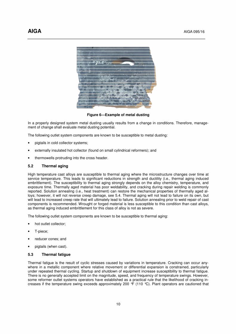
No alloy is truly resistant to metal dusting; however, some alloys are more resistant than others. Metal dusting is mitigated by designing the process condition outside of the metal dusting range. Care shall be taken to en-sure design temperatures, pressures, and compositions are maintained during operation. Non-uniformity in temperature or composition can result in localized metal dusting. For example, damaged or missing insulation can lead to localized cooling resulting in a portion of the component being within the metal dusting range, see Figure 6.
AIGA
In a properly designed system metal dusting usually results from a change in conditions. Therefore, managment of change shall evaluate metal dusting potential.
The following outlet system components are known to be susceptible to metal dusting:
• pigtails in cold collector systems;
• externally insulated hot collector (found on small cylindrical reformers); and
• thermowells protruding into the cross header.
5.2 Thermal aging
High temperature cast alloys are susceptible to thermal aging where the microstructure changes over time at service temperature. This leads to significant reductions in strength and ductility (i.e., thermal aging induced embrittlement). The susceptibility to thermal aging stronexposure time. Thermally aged material has poor weldability, and cracking during repair welding is commonly reported. Solution annealing (i.e., heat treatment) can restore the mechanical properties of thloys; however, it will not reverse creep damage, see 5.4. Thermal aging will not lead to failure on its own, but will lead to increased creep rate that will ultimately lead to failure. Solution annealing prior to weld repair of cast components is recommended. Wrought or forged material is less susceptible to this condition than cast alloys, as thermal aging induced embrittlement for this class of alloy is not as severe.
The following outlet system components are known to be susceptible to th
• hot outlet collector;
• T-piece;
• reducer cones; and
• pigtails (when cast).
5.3 Thermal fatigue
Thermal fatigue is the result of cyclic stresses caused by variations in temperature. Cracking can occur anwhere in a metallic component where relative under repeated thermal cycling. Startup and shutdown of equipment increase susceptibility to thermal fatigue. There is no generally accepted limit on the magnitude, speed, and frequency of temsome reformer outlet systems operators have established as a practical rule that the likelihood of cracking icreases if the temperature swing exceeds approximately 200 °F (110 °C). Plant operators are cautioned that
10
Figure 6—Example of metal dusting
In a properly designed system metal dusting usually results from a change in conditions. Therefore, managment of change shall evaluate metal dusting potential.
components are known to be susceptible to metal dusting:
pigtails in cold collector systems;
externally insulated hot collector (found on small cylindrical reformers); and
thermowells protruding into the cross header.
alloys are susceptible to thermal aging where the microstructure changes over time at service temperature. This leads to significant reductions in strength and ductility (i.e., thermal aging induced embrittlement). The susceptibility to thermal aging strongly depends on the alloy chemistry, temperature, and exposure time. Thermally aged material has poor weldability, and cracking during repair welding is commonly reported. Solution annealing (i.e., heat treatment) can restore the mechanical properties of thloys; however, it will not reverse creep damage, see 5.4. Thermal aging will not lead to failure on its own, but will lead to increased creep rate that will ultimately lead to failure. Solution annealing prior to weld repair of cast
ts is recommended. Wrought or forged material is less susceptible to this condition than cast alloys, as thermal aging induced embrittlement for this class of alloy is not as severe.
The following outlet system components are known to be susceptible to thermal aging:
Thermal fatigue is the result of cyclic stresses caused by variations in temperature. Cracking can occur anwhere in a metallic component where relative movement or differential expansion is constrained, particularly under repeated thermal cycling. Startup and shutdown of equipment increase susceptibility to thermal fatigue. There is no generally accepted limit on the magnitude, speed, and frequency of temperature swings. However, some reformer outlet systems operators have established as a practical rule that the likelihood of cracking icreases if the temperature swing exceeds approximately 200 °F (110 °C). Plant operators are cautioned that
AIGA 095/16
In a properly designed system metal dusting usually results from a change in conditions. Therefore, manage-
components are known to be susceptible to metal dusting:
alloys are susceptible to thermal aging where the microstructure changes over time at service temperature. This leads to significant reductions in strength and ductility (i.e., thermal aging induced
gly depends on the alloy chemistry, temperature, and exposure time. Thermally aged material has poor weldability, and cracking during repair welding is commonly reported. Solution annealing (i.e., heat treatment) can restore the mechanical properties of thermally aged al-loys; however, it will not reverse creep damage, see 5.4. Thermal aging will not lead to failure on its own, but will lead to increased creep rate that will ultimately lead to failure. Solution annealing prior to weld repair of cast
ts is recommended. Wrought or forged material is less susceptible to this condition than cast alloys,
ermal aging:
Thermal fatigue is the result of cyclic stresses caused by variations in temperature. Cracking can occur any-movement or differential expansion is constrained, particularly
under repeated thermal cycling. Startup and shutdown of equipment increase susceptibility to thermal fatigue. perature swings. However,
some reformer outlet systems operators have established as a practical rule that the likelihood of cracking in-creases if the temperature swing exceeds approximately 200 °F (110 °C). Plant operators are cautioned that
AIGA AIGA 095/16
11
this limit may not apply to all reformer designs. Consult the furnace designer to determine the appropriate tem-perature limit.
System damage can also occur due to repeated changes in surface temperature resulting in a thermal gradient through the thickness or along the length of a component. For example, cold water on a hot tube (i.e., thermal shock), rigid attachments and a smaller temperature differential, and the inability to accommodate differential expansion due to temperature changes.
Thermal fatigue is typically an issue at the branch connections of hot outlet headers. Contributing factors in-clude constraint, thermal expansion coefficient, large temperature variation, and high frequency of cycling. The attachment welds are susceptible to cracking due to high thermal stresses in the heat affected zone (HAZ). High temperature and pressure variations should be included in the initial design (i.e., upset conditions). ASME B31.3, Process Piping defines allowances for pressure and temperature variations and provides rules for calculating thermal expansion stresses and allowable displacement stress range [2]. A more detailed stress analysis is sometimes appropriate depending on the specific problem. Rules for detailed stress analysis can be found in the ASME Boiler and Pressure Vessel Code, Section VIII, Div 2 [3].
All materials with cyclic stresses are considered susceptible material.
5.4 Creep
At high temperatures metal components can slowly and continuously deform under load below the yield stress. The time-dependent deformation that occurs under stress is known as creep. Creep is the primary damage mechanism for materials in this application. Table 1 contains threshold temperatures for different alloys above which creep can occur. Creep is mitigated by proper design and material selection.
Table 1—Threshold temperature for creep
Alloy Threshold temperature
Carbon steels 700 °F (371 °C)
Cr-Mo steels 800 °F (427 °C)
Austenitic stainless steels 900 °F (482 °C)
High nickel alloys 1100 °F (593 °C)
Source: API 571, Damage Mechanisms Affecting Fixed Equipment in the Refining Industry [4].
Material in this service is weakened by thermal aging over time, which increases the rate of creep. Creep oc-curs in three stages starting with voids in the metal that align to form fissures. The fissures ultimately form cracks that lead to failure of the component. The rate of damage accelerates at the onset of cracking. These two mechanisms are interrelated and ultimately lead to failure of the components.
The following outlet system components are known to be susceptible to creep:
• hot header and support members;
• T-piece;
• reducer cones;
• pigtails and attachment components (e.g., weld-o-let, sock-o-let); and
• welds connecting these components.
5.5 Excessive stress
Outlet systems are designed considering all normal operating conditions. These conditions include internal pressure, temperature, weight, and thermal expansion. Stresses due to these conditions are kept within the relevant code limits or other more conservative limits established by the furnace designer. Stresses that are higher than the design limits can develop due to improper construction, unexpected behavior, or improper

AIGA AIGA 095/16
12
maintenance of the piping support system. These conditions often result in excessive bending stresses that have been shown to drastically reduce the life of the piping system. Of particular concern are welds and weld HAZ in hot collectors, which are less tolerant than the base metal.
5.6 Stress corrosion cracking
Stress corrosion cracking (SCC) is a condition that requires the simultaneous presence of a susceptible mate-rial, a tensile stress, and a susceptible environment. The tensile stress can be caused by the applied stress and residual stress from welding. The most common environment that causes SCC of austenitic alloys is chlorides and caustics in aqueous conditions. The resistance to SCC increases with increased nickel content in the al-loys.
Outlet system components are made of materials that can be subject to SCC; however, under normal operating conditions a susceptible environment to promote SCC should not exist. Upset conditions can lead to the devel-opment of a susceptible environment.
5.7 Stress relaxation cracking
Stress relaxation cracking is also known as stress relief cracking, postweld heat treatment cracking, and stress assisted grain boundary oxidation (SAGBO). This condition involves cracking at grain boundaries that occurs when the material cannot accommodate deformation due to limited ductility. It is most often observed in com-ponents with heavy wall sections under high stress. Stress relaxation cracking normally occurs at temperatures between 930 °F and 1380 °F (499 °C and 749 °C) and often is mistakenly diagnosed as creep failure. A proper-ly conducted postweld heat treatment or post fabrication heat treatment is effective in preventing stress relaxa-tion cracking.
The following outlet system components are known to be susceptible to stress relaxation cracking:
• hot outlet collector and support members including reinforcing pads;
• T-piece;
• reducer cones; and
• pigtails and attachment components (e.g., weld-o-let, sock-o-let).
5.8 High temperature hydrogen attack
High temperature hydrogen attack (HTHA) results from exposure to hydrogen at elevated temperatures and pressures. The hydrogen reacts with carbides in steel to form methane (CH4), which cannot diffuse through the steel. The loss of carbide causes an overall loss in strength. The methane pressure builds up forming bubbles or cavities, micro fissures, and fissures that can combine to form cracks. Failure can occur when the cracks reduce the load carrying ability of the pressure containing part. API RP 941 provides guidelines on the use of steels in hydrogen service at elevated temperatures and pressures [1].
Material selection using the Nelson curves from API RP 941 requires a safety margin to be applied [1].
The following outlet system components are known to be susceptible to hydrogen attack:
• carbon steel or low alloy steel shell of the cross header or cold collector; and
• exterior shell of the cold pigtail.
5.9 Hydrogen embrittlement
Hydrogen embrittlement is the degradation of material properties due to the presence of hydrogen. Hydrogen embrittlement manifests itself as reduction in tensile strength and ductility, accelerated fatigue crack growth, and cracking under sustained load. The susceptibility to hydrogen embrittlement is strongly dependent on the materials’ strength and hydrogen environment. Similar to stress corrosion cracking, a tensile stress is required for hydrogen embrittlement to occur. Hydrogen embrittlement is most likely to occur at near ambient tempera-

AIGA AIGA 095/16
13
tures. Hydrogen embrittlement is not likely to occur at temperatures higher than 300 °F (149 °C). This condi-tion is not common because the temperature of most hot outlet system components is higher than 300 °F (149 °C); however, the cold collector or cross header shell could be susceptible particularly at welds or HAZ if welding is not done properly.
5.10 Material deformation due to high temperature (bulging at hot spots)
Components in the outlet system can deform permanently if exposed to high temperatures beyond the original design conditions, usually the result of internal insulation degradation or failure. Localized permanent defor-mation presents a significant risk to the structural integrity of the outlet system.
The following outlet system components are known to be susceptible to bulging:
• carbon steel or low alloy steel shell of the cross header or the cold collector; and
• exterior shell of a cold pigtail.
5.10.1 Dissimilar weld cracking
Cracking of dissimilar metal welds occurs on the ferritic side of a weld between a ferritic material (e.g., carbon steel or low alloy steel) and a high alloy austenitic material operating at high temperature. The condition most often occurs with carbon steel and low alloy steels that are welded to the austenitic nickel-based alloy with dif-ferent thermal expansion coefficients.
The following outlet system components are known to be susceptible to dissimilar weld cracking:
• nickel alloy reducer cone to carbon steel or low alloy steel shell of a cross header; and
• nickel alloy exterior shell of a cold pigtail to a cold collector tube stub.
5.11 Nitridation and carburization
The surfaces of outlet systems are exposed to high temperature syngas on the inner side of the pipe, and high temperature air on the outer side of the pipe, promoting the diffusion of nitrogen into the surface of the metal and leading to the formation of nitrides. Nitridation can lead to a reduction in ductility of metallic components.
Carburization occurs when carbon from the environment diffuses in the alloy and reacts with iron chromium and other carbide-forming elements to form carbides. Carburized metal increases in hardness and becomes brittle. In-service failures due to these conditions are rare, but the reduction in ductility due to carburization and nitridation can affect the reparability of the outlet system components.
The following outlet system components are known to be susceptible to these conditions:
• exterior insulated hot collector and hot pigtail (nitridation); and
• metal liner inside of refractory insulated cross header or cold collector (carburization).
5.12 Insulation failure
A number of the previously mentioned failure modes are associated with degradation of insulation that leads to temperatures that are outside the normal operating envelope.
External fibrous or solid insulation is susceptible to mechanical damage and deformation due to low compres-sive strength properties. A direct consequence of thermal insulation degradation is detrimental cooling of hot components. This cooling can lead to metal dusting, excess thermal stress, or undesired condensing in upset conditions. Damage to external solid insulation will also lead to improper support of the outlet system resulting in excess external stress.
Internal castable insulation is susceptible to various forms of mechanical damage (e.g., cracking, spalling, ero-sion) as well as to corrosion due to oxidation, sulfidation and other high temperature mechanisms. Refractory

AIGA AIGA 095/16
14
degradation mechanisms include erosion (i.e., result of velocity), spalling (i.e., loss of surface layer due to thermal or mechanical stresses), cracking (i.e., result of tensile forces from mechanical loads), structural dete-rioration (i.e., detachment from anchor), and chemical attack (i.e., result of reactive substances). An example of chemical attack is process gas permeation into the internal insulation that subsequently condenses and de-grades the insulation material. Insulation damage or degradation will increase the shell temperature which can result in high temperature failure mechanisms of the metallic components. Migration of the insulation material can result in fouling of downstream heat exchangers.
Improper application of additional external insulation on air-cooled shell components can result in overheating of the shell or condensation under the shell. Transitions from air cooled or externally insulated components to internally insulated components shall be monitored to ensure they remain as designed.
5.13 Summary of failure modes and components
Table 2 summarizes the locations in the syngas outlet system where failure has been known to occur. The ta-ble is not meant to represent an all-inclusive list of failure locations, but rather to summarize the information in previous sections.

AIGA AIGA 095/16
15
Table 2—Failure modes associated with syngas outlet system components
Hot Outlet System Cold Outlet System Common
Components
Pig
tail
Hot
outlet
colle
cto
r
T-p
iece
Reducer
cone
Cro
ss h
eader
Cold
pig
tail
Hot
pig
tail
Cold
outlet
colle
cto
r
Cro
ss h
eader
Supp
ort
mem
bers
Cro
ss h
eader
th
erm
ow
ells
Metal dusting X 1) X X X
Thermal aging 2) X X X X X X
Thermal fatigue X X X X X
Creep X X X X X X
Excessive stress X X X X
Stress relaxation cracking X X X X X X
High temperature hydrogen attack
X X X X
Hydrogen embrittlement X X X
Material deformation X X X X
Dissimilar weld cracking X 3) X 3) X 3) X 3)
Nitridation X 1) X 1) X 1)
Carburization X X
1) Externally insulated components only.
2) Applies to cast components only.
3) Dissimilar weld cracking occurs in the reducer cone to the cross header, and the cold pigtail to the cold collector welds.
6 Monitoring and inspection during plant operation
6.1 General and safety considerations
Syngas outlet systems shall be monitored regularly while also ensuring process conditions remain within the design operating envelope to avoid the failure modes outlined in Section 5. Any abnormalities identified by the methods described below should be promptly investigated, and a list of deficiencies should be collected for correction during available maintenance opportunities.
When making visual observations of the outlet system components, care should be taken due to the potential hazards associated with the area. The surface of any refractory-lined or externally insulated component is hot enough to burn personnel if contacted. Depending on the design of the outlet system, the area underneath of the reformer can have limited access/egress, creating a hazardous enclosure. If a leak were to develop in an outlet system component, the leaking gas would be flammable, toxic, and at high temperature. Due to the high temperature of the gas, any leak is likely to ignite. Failure of the component can proceed rapidly and cata-strophically.
For these reasons, access to the area underneath of the reformer should be restricted. The area should be accessed only for the purpose of inspection or maintenance. Prior to accessing the area, monitor the area from the boundary to detect any significant defects. The inspection can be done visually or with a thermal imaging

AIGA AIGA 095/16
16
camera (see 6.3.3.2). If any significant defects are identified from the boundary, the area under the reformer should not be entered and a shutdown of the plant should be initiated. When accessing the area, flame retard-ant clothing should be worn. Combustible gas monitors and fixed flame detection can also provide additional layers of protection.
6.2 Visual observations
Visual observation is an important aspect of plant monitoring during both startup and subsequent operation. It is important to periodically monitor both internally and externally insulated components to identify any abnor-malities, and to mitigate any impact from the failure modes described in Section 5.
6.2.1 Bulging or glowing
The exterior surface of refractory lined piping should be monitored for hot spots. Refractory lined piping typical-ly has a steel pressure boundary with a design temperature limit between 600 °F and 1100 °F (316 °C and 593 °C) at the design pressure of the pipe. The temperature of the gas inside the refractory lined interior can exceed 1600 °F (871 °C). As this steel “pipe” surface is typically rolled plate, if a hot spot begins to develop, it will warp due to uneven heating. If serious enough, the surface will bulge due to pressure on the softened material. Ultimately, overheating will lead to failure of the pressure envelope resulting in an energy release.
In addition, the steel pressure boundary is subject to high temperature hydrogen attack. Depending on the ma-terial type, the observation and countermeasure plan should include specific guidance on when to apply cooling and when to shut down the unit. See Section 7 for mitigating actions.
6.2.2 External insulation
Externally insulated components should be inspected for gaps or damaged insulation. Visibly glowing pipe ex-posed to ambient conditions can impart large thermal stresses on the outlet system components.
6.2.3 Support system
The position of piping and supports should be inspected to ensure the system is expanding as intended, and that it is properly supported. Springs should be inspected, and the indicator should be confirmed to be near the hot position. Outlet systems that utilize fixed supports should be inspected to ensure that the fixed support is engaged on the outlet component. Refer to the engineering drawings for proper positions and acceptable toler-ances.
Some externally insulated hot collectors utilize supports that are independent of the reformer box. This allows stable support independent of box movement due to thermal expansion. Insulation or some type of thermal break separates the support from the hot component. Mechanical damage of either the support components or the insulation will adversely affect the support. External support components will display signs of overheating if the thermal break is damaged (e.g., burnt paint, discoloration).
Hot collectors contained inside reformer boxes sometimes utilize supports that are independent of the box. This allows stable support independent of box movement due to thermal expansion. The support is attached to, or slides on, the hot subheader. Insulation or some type of thermal break separates the hot portion of the support from the cold portion of the support. The position of the supports should be inspected to ensure the system is expanding as intended and that it is properly supported. The slide plate position should be observed to deter-mine whether witness marks (i.e., scuff marks) exist on the plate to assure plate motion is sufficient and is not frozen. External support components will display signs of overheating if the thermal break is damaged (e.g., burnt paint, discoloration).
6.2.4 Geometric alignment
Components that are not properly supported or are constrained can permanently deform, affecting the overall integrity of the outlet system. Common issues include drooping pigtails and bowing hot collectors or cross

AIGA AIGA 095/16
17
headers. Deviations in position or shape from the system design should be tracked and reported for further investigation.
6.3 Outlet system temperature monitoring
In addition to periodic visual monitoring for signs of defects, the temperature of the outlet system components should be monitored to determine if any component is operating above its design temperature. Because the temperature of the outlet system components, particularly the outlet pigtails and outlet collectors, is directly affected by the individual reformer tube temperatures, reformer tube temperatures should be monitored for signs of imbalance. Temperature imbalance can indicate why some outlet components are approaching or ex-ceeding design temperature.
6.3.1 Tube temperature monitoring
Each reformer tube is an individual reactor that can deviate from the desired operating temperature over the length of the tube and around the circumference. This condition can lead to temperature imbalances within the reformer box resulting in temperature deviations in portions of the outlet system. Routine surveillance of re-former tube temperatures will reveal temperature imbalances. Methods for monitoring reformer tube tempera-tures include contact thermocouples, hand-held pyrometers (optical or laser), or digital imaging.
Operating procedures shall address how to balance temperatures within the furnace so that temperature differ-ences among reformer tubes do not result in exceeding the design temperature of any outlet system compo-nents. See 7.1 for guidance on balancing.
6.3.2 Externally insulated piping
Some reformer designs have continuous temperature monitoring via thermocouples on the tube skin on the pigtails, and/or in the process gas of the outlet collectors. If available, these temperature measurements can be used to identify imbalances and deviations from design limits.
If continuous temperature monitoring is not available, outlet system component temperatures can be estimated from reformer tube temperature measurements. Estimates of outlet system component temperatures should account for the reforming reaction as well as for the heat transfer that occurs between the point at which tem-perature is measured on the tube and the outlet system component. Additional plant process data (e.g., pres-sures, flows, composition) can be used to improve the accuracy of temperature estimates. Temperature esti-mates can be used to identify imbalances and deviations from design limits.
6.3.3 Internally insulated equipment
Because the external steel pressure boundary of internally insulated piping and equipment is accessible for inspection, there are more options for monitoring surface temperature than in the case of externally insulated components. It should be recognized that the internal surface temperature of the component is higher than the external surface temperature.
6.3.3.1 Indicating paint
One method for monitoring the surface of refractory lined equipment is to coat the component with a tempera-ture sensitive paint and to observe whether the heat sensitive paint has changed color. Temperature indicating paint does not measure temperature, but changes color within a specific temperature range. A color change is intended to alert the operator to high metal temperature.
As this paint is difficult to apply and maintain, the color change can also indicate failure of the paint system ra-ther than a rise in temperature. Therefore, the paint condition should also be monitored. Repainting should be done if the paint has faded or has otherwise been damaged. This method shall be supplemented with monitor-ing via infrared thermography.

AIGA AIGA 095/16
18
6.3.3.2 Infrared devices
Heat conducted through air is infrared (IR) light, and there are a variety of instruments that make use of this principle to measure temperature. Line of site devices (IR guns) and IR cameras are the most useful. IR guns measure the temperature surrounding the location indicated by the laser beam. IR guns allow plant operators to scan refractory lined equipment to monitor for hot spots. IR cameras take a thermal image of the equipment and provide more detailed information useful in evaluating the condition of refractory lined equipment. These devices can typically take visible light digital photos and can be used to document the condition of the surface of refractory lined pipe.
A combination of IR guns and hand-held or permanent IR cameras should be used to measure metal tempera-tures of refractory lined piping and equipment. Hand-held IR cameras can be used to verify proper operation of continuous monitoring systems. They can also be used to characterize and monitor known or suspected hot spots. Proper calibration and background correction shall be performed to ensure the accuracy of the tempera-ture measurement.
6.3.3.3 Contact thermocouples
Contact thermocouples can be used as permanent temperature measuring devices or as re-locatable devices to monitor hot spots.
6.3.3.4 Temperature sensitive tubing
Temperature sensitive tubing does not measure temperature, but melts within a known temperature range alerting the operator to high metal temperature. The alert can be a pressure or flow alarm due to loss of pres-sure or flow inside the tubing. Ultraviolet light degrades most polymeric tubing; therefore, the tubing should be monitored and replaced when degraded. Degraded tubing can fail prematurely without the presence of a hot spot.
7 Online remedial action
7.1 Temperature balancing of furnace
Temperature balancing techniques vary based on the furnace design. The operator should develop a method-ology to adjust and maintain an appropriate temperature balance within the furnace to reduce temperature var-iation throughout the outlet system based on the recommendations of the furnace designer.
7.2 Temperature mitigation (cooling hot spots)
If the refractory within a component is damaged or degraded, a hot spot will form due to the reduced insulating effect of the refractory. Rapid changes in surface temperatures can occur if the refractory continues to degrade. Hot spots can be susceptible to material deformation (see 5.10) or hydrogen attack (see 5.8). Depending on the material, the maximum allowable operating temperature can be different for these two phenomena. The operator shall determine temperature limits at which to begin monitoring, apply cooling, or shut the unit down.
Regular monitoring of the outlet system component is required to determine the normal range of variation in temperature due to variations in surface temperature that are expected with changes in ambient and operating conditions. If monitoring reveals an area of rising surface temperature of the steel pressure boundary, the moni-toring interval should be shortened. The temperature at which the monitoring interval should be shortened will be above the normal range of surface temperatures, but well below the design temperature of the component. A typical point at which temperature monitoring should increase is 45 °F (25 °C) higher than the maximum normal surface temperature. If a hot spot has been identified, the frequency of monitoring should be no less than daily, but can be more frequent.
If the surface temperature continues to rise, the operator shall determine the point at which remedial action must be taken. The rate of the temperature increase, the expected cause of the refractory degradation, and the difference between the normal surface temperature and the design temperature of the component will help de-termine the point at which action needs to be taken. Hot spot temperatures can be reduced below the design

AIGA AIGA 095/16
19
metal temperature by applying either cooling air or steam. However, applying excessive cooling can result in internal condensation that will damage the steel pressure boundary. Application of cooling is a temporary measure that is taken until the hot spot can be repaired. Action should be taken below the design temperature of the component since it can take some time to implement any action. In addition, the operator must have time to shut down the plant prior to exceeding the design temperature of the outlet system component in the event the remedial action fails to control the hot spot temperature.
If temperature mitigation is not successful in lowering the metal temperature below the design metal tempera-ture, the affected piping or equipment should be taken out of service in order to avoid potential loss of contain-ment. The temperature at which the piping or equipment is taken out of service should be no higher than the design temperature of the outlet system component, but may be lower. The action temperature should be de-termined by the operator based on several factors, including the rate of surface temperature increase, the likely cause of refractory degradation, the speed at which shutdown can be implemented, the available frequency of surface temperature monitoring, the size of the hot spot, etc.
Once the equipment has been taken out of service, an inspection should identify the cause of the refractory degradation. The inspection should determine whether changes in the refractory design can reduce the likeli-hood of hot spot formation. If the surface temperature has either exceeded the design temperature or gone below the dew point of the process (i.e., due to excess cooling), the condition of the steel pressure boundary should be evaluated. If necessary, a fitness for service analysis shall be performed in accordance with API 579-1/ASME FFS-1, Fitness-For-Service to identify the risk of continuing operation [5].
7.2.1 Remedial action for hot spots
The first stage of remedial action involves the use of one of several methods of external cooling. Excessive cooling shall be avoided to prevent condensation on the interior or further damage to the refractory and shell by thermal stresses. For these reasons, the use of water as a cooling medium is not recommended. Further, the use of water as a cooling medium can result in SCC due to the presence of water treatment chemicals.
If cooling is applied, increased temperature surveillance of the affected area should be performed to verify that the refractory condition does not continue to degrade. This can be accomplished using a magnetic contact thermocouple or IR technology. Local temperature monitoring routed to an alarm system is recommended for locally cooled areas in order to alert plant personnel to a change in conditions.
Dry air, nitrogen, or dry steam is suitable cooling media. If multiple sources of steam are available for cooling, the source that is closest to but does not exceed the design temperature of the equipment is best. Dry air or nitrogen can also be applied, and the cooling impact of either can be enhanced by the addition of steam to hu-midify the cooling medium. Use of nitrogen as a forced cooling agent in an enclosed area is a potential asphyx-iation hazard. Use of air can increase the potential for combustibility if a leak develops, while use of nitrogen or steam dilutes the flammable gas in the event of a leak.
If air or nitrogen is used for cooling, it should be applied with an air horn or other air mover rated for the area classification. The air or nitrogen can be humidified by positioning a steam hose such that the air educts some of the steam. If steam is utilized, the steam should be applied by some type of shaped sparger (i.e., ring with multiple nozzles) in order to cool the equipment evenly and thoroughly and to avoid localized cooling. Surface temperature should be closely monitored using contact thermocouples. Once cooling is applied, temperature measurement by IR thermographic methods can be misleading (i.e., indicating steam temperature and not the metal surface temperature). Note that rapid changes in surface temperature can occur; therefore, monitoring shall be performed multiples times per shift.
The temporary cooling system should be operated in accordance with written procedures. Regular visual ob-servation and monitoring of temperatures shall be performed. If plant air is being used and the potential for it to be backed up by nitrogen exists, warning signs should be in place and the area should be appropriately barri-caded. In addition, any valves associated with the flow of the cooling stream should be locked open and tagged appropriately to ensure that flow of the cooling stream is not compromised. The action point where a plant shutdown is required should be clearly outlined in the written procedures.

AIGA AIGA 095/16
20
8 Offline maintenance and inspection
8.1 Hot collector (inside of furnace) and hot pigtails (inside of furnace or outside of furnace/ externally insulated)
8.1.1 Inspection
High nickel alloy material is subject to thermal aging and creep failure. Normal aging and creep failure will man-ifest as external expansion and internal cracking. The large transition in temperature between the inside and outside of the firebox wall indicates that the header is often subject to uneven stress caused by heat-up, cool-down, and uneven support. The design of the system accounts for hoop stress and other stress due to external forces. Any unaccounted for externally applied lateral or vertical forces can lead to cracking and failure. Uneven external stresses typically manifest as external cracks. As the plant ages, the system shall be inspected to as-sure conditions remain as the designer intended. Unaccounted for conditions shall be evaluated when they are discovered.
Once discovered, the source of increased stress shall be identified and eliminated. Fitness for service analysis shall be performed in accordance with API 579-1/ASME FFS-1 [5]. Increased local stresses can also lead to cracking if the material is embrittled due to thermal aging. Proper design and maintenance of the outlet piping system is essential in order to eliminate excessive stress and prevent premature failure. Additionally, piping systems should be designed with sufficient flexibility so that the type and location of supports does not cause excessive stress and allows for adequate thermal expansion and contraction.
Further details on nondestructive testing methods can be found in the ASME Boiler and Pressure Vessel Code, Section V [3].
8.1.1.1 Liquid penetrant testing
Liquid penetrant testing (LPT) can be used to identify external cracking on hot collectors with minor surface preparation (i.e., abrasive removal of oxide to clean metal). Cracks tend to be circumferential and appear in the weld, HAZ, and base material. Overstress due to bending movements of the support system leads to external cracking. Early onset of this failure mode is best detected with LPT.
8.1.1.2 Radiographic testing
Radiographic testing (RT) can be used to identify internal and external cracking, but it is primarily used for weld acceptance of repair welds. RT is less useful than LPT for early detection (see 8.1.1.1), as cracks must be of a significant size to be detectable. It is most useful for proving the absence of internal defects during a weld re-pair.
8.1.1.3 In-situ metallography
In-situ metallography is used to perform a detailed examination of the external surface grain structure. The use of replicas and field microscopes are common methods used to conduct in-situ metallography. Results can be used to interpret thermal aging of the header material. Thermal aging is an indication of the progression of creep.
8.1.2 Hot collector support inspections
Some hot collectors have supports that are integral parts of the furnace box, forcing the header to conform to the shape of the box. This condition can put unforeseen stress on the hot collector. Therefore, the hot collector and supports shall be inspected for signs of damage.
Some hot collectors have supports that are independent of the furnace box, allowing stable support independ-ent of box movement due to thermal expansion. These supports have components that operate at system tem-perature, and components that operate at ambient temperature. There is insulation or some type of thermal break separating the two sections of the support. Mechanical damage of either the support components or the insulation will adversely affect the support.

AIGA AIGA 095/16
21
8.1.2.1 Slide plate position
When the unit is down, the slide plate position should be observed to determine whether witness marks (i.e., scuff marks) exist on the plate. Relative motion should be confirmed to be sufficient (i.e., the slide is not stuck in position).
8.1.2.2 Spring supports
When the unit is down, spring supports should be inspected to confirm the indicators are in the cold position. The condition of the springs should be observed for breakage or excessive corrosion. When the unit is running, confirm the indicators are near the hot position.
8.1.3 Weld repair of high temperature heat resistant alloys
High temperature heat resistant alloys used in the outlet system normally have appropriate weldability in the as-supplied (i.e., new) condition. Therefore, welding in new construction is relatively straightforward. However, these alloys, especially castings, are susceptible to thermal aging at normal operating conditions that can lead to significant reduction in ductility and weldability. Cracking can occur during or after welding in thermally aged material. Extreme caution shall be taken when performing repair welding on thermally aged alloys in order to prevent weld cracking and other defects. The susceptibility to thermal aging strongly depends on the alloy chemistry, operating temperature, and length of time the component has been in service. Because many com-mon alloys in the outlet system are proprietary (i.e., not covered in any material specification or construction code), the selection of weld method and consumables can be complicated. Prior to the weld repair, the repair welding procedure specification (WPS) and associated procedure qualification record (PQR) should be devel-oped based on the actual alloys in the aged condition.
8.1.3.1 Solution annealing heat treatment
Local solution annealing (i.e., weld and a few inches to either side) is an effective heat treatment method to restore the ductility and weldability of thermally aged alloys. Thermally aged components have been success-fully welded after solution annealing in the field. Solution annealing prior to repair welding is strongly recom-mended. The effectiveness of solution annealing should be verified by WPS/PQR. The heating and cooling rate should be controlled to minimize possible damage due to thermal stresses during the heat treatment. Adequate support should be in place while components are in a weakened condition (i.e., when hot).
8.1.3.2 Weld joint preparation
Weld joint preparation should be performed via grinding or machining to remove damaged material. Machining is recommended as it results in lower residual stress. Non-destructive examination (NDE) should be performed to ensure the weld joint preparation is free of defects.
8.1.3.3 Welding and filler metal selection
Back purging shall be applied using inert gas so that the root pass can obtain acceptable root contour that is free of oxidation. Proper interpass temperature should be maintained during fill passes. At a minimum, NDE should be performed after the root weld and after completion of the weld repair to ensure the repair weld is free of defects. Proper filler metal should be selected based on the service temperature and stress condition. Choice of weld filler metal other than what was used in the original construction should be based on engineer-ing analysis.
8.2 Connection of tube to cold collector or hot collector to transition line
A transition piece made of high alloy steel and internally lined with refractory is commonly used by reformer designers when connecting a catalyst tube or hot collector to a cold collector. As a result, the outer shell of the steel has a progressive temperature gradient until the temperature is compatible with the use of lower alloy steel or carbon steel.

AIGA AIGA 095/16
22
A typical transition piece includes either a tube-in-tube or a tube-in-cone (i.e., reducer cone) designed to adapt to various dimensions between the catalyst tube or hot collector on one side, and the cold collector/transition line at the other side. High grade material such as 20Cr-32Ni or higher is used. The space between the outer shell and inner tube is filled with insulating refractory castable or vacuum formed fiber material.
If the insulating material is damaged or has cavities due to thermal cycling, the heat transfer from the inner tube to the outer shell will be affected. This could potentially lower the temperature of the inner tube into the metal dusting range and raise the outer shell temperature into the hydrogen attack range. Either situation could lead to pressure boundary failure.
8.2.1 Inspection
Similar to hot pigtails and hot collectors, the outer shell of the transition piece to a cold collector is subject to thermal aging, creep failure (see 8.1.1), and dissimilar weld cracking (see 5.10.1).
8.2.1.1 Liquid penetrant testing
With minor surface preparation (i.e., abrasive removal of oxide to clean metal), LPT can be used to identify ex-ternal cracking on the transition piece. Potential cracks tend to be circumferential and will appear in the weld, HAZ, or base material.
8.2.1.2 Radiographic testing
RT can provide a shadowy indication of missing refractory material. RT can provide sufficient information for positioning external injection ports, see 8.3.5.3. RT can also be used to identify loss of thickness of the inner tube due to metal dusting. Due to severe geometric uncertainty, RT shall not be used to determine the remain-ing thickness of the inner tube, or the actual material thickness or dimensions of cavities.
8.2.1.3 In-situ metallography
In-situ metallography is used to perform a detailed examination of the external surface grain structure. The use of replicas and field microscopes are common methods used to conduct in-situ metallography. Results can be used to interpret thermal aging of the header material. Thermal aging is an indication of the progression of creep.
8.2.2 Weld repairs
See 8.1.3.
8.2.3 Mitigation of metal dusting
Metal dusting is due to a detrimental temperature change in the material. Prompt action should be taken to re-pair or replace insulation to ensure the metal temperature is outside the metal dusting range.
8.3 Refractory lined pipe
Failures in the refractory lined pipe (i.e., cold collector, transition line, etc.) are typically due to overheating of the external steel pressure boundary. Overheating is due to degradation of the insulating properties of the re-fractory (e.g., cracking, loss of material).
8.3.1 Inspection
Observation and monitoring during operation in accordance with Section 6 will typically reveal where detailed inspection is required during a shutdown.
8.3.2 Ultrasonic thickness measurement
Simple ultrasonic thickness measurement (UTM) can identify the difference between a bulge and a blister. A bulge is material pressed outward by pressure with insignificant wall thickness change. A blister is a gas-filled

AIGA AIGA 095/16
23
lamination pressing inward and outward on the material that when measured will show significantly reduced wall thickness. The external appearance of a blister and a bulge is similar, see API RP 941 [1].
8.3.3 Radiographic testing
RT can provide a shadowy indication of missing refractory material. Due to its severe geometric uncertainty, RT shall not be used for determining thickness or dimensions of cavities. RT may require a hot source and a large safety boundary, and therefore may be impractical. RT provides sufficient information for positioning external injection ports, see 8.3.5.3.
8.3.4 Internal inspection
Refractory lined cold collectors are constructed of multiple layers of material selected for their insulating proper-ties and resistance to high temperatures and erosion. A typical lining arrangement is comprised of a thin hot face layer in contact with the syngas, and a thick back layer attached to the casing by an anchoring system.
The hot face layer can be of metallic or refractory material and should be resistant to temperature, erosion, and the reducing atmosphere of the syngas.
The metallic inner liner is typically made of high grade material similar to that used for hot collectors (20Cr-32Ni or equivalent). However, the thickness is not determined by the internal pressure as it is not a pressure bound-ary.
Refractory castable or shaped brick lining is typically high density with high alumina content (more than 90% aluminum oxide), and low iron and silica content (less than 0.1% ferric oxide and 0.1% silicon dioxide).
The back layer is made of insulating castable or bricks made of alumina and silica (typically 45% aluminum oxide and 35% silicon dioxide) and low iron content, with low thermal conductivity properties.
The pressure boundary of the cold collector is highly dependent on the refractory condition. In the case of a hot spot due to damage or loss of refractory material, the metal temperature of the cold collector casing can rapidly exceed its design temperature leading to a loss of containment.
Internal inspection of the cold collector should include visual inspection of the hot face layer that is accom-plished by accessing the interior through the manhole. If the inside diameter or atmosphere does not allow for safe personnel access, a remote camera or boroscope may also be used.
Visual inspection of the metallic inner liner should include observation of the surface condition of the liner for:
• deformation or damage;
• corrosion evidence (e.g., pitting, metal dusting); or
• any defect that may prevent free displacement of the liner during operation.
In the case of a refractory castable or brick-lined collector, visual inspection should include observation of the surface condition of the inner surface and inspecting for cracks or material loss.
Simple stress cracks that are essentially closed when hot are common and do not require remedial action. When inspecting in the cold condition, an acceptable stress crack would typically be less than 1/8 in wide. Open cracks where material is missing (i.e., are not closed when hot) can lead to gas flow through the insulat-ing layer. This gas flow will ultimately reach the steel pressure boundary and will cause the surface temperature to rise. Gas flow through the insulating layer will cause silica migration and wastage of the insulating layer. This wastage will form cavities behind the hot face layer. Cavities will result in the collapse of the hot face layer and subsequent overheating of the steel pressure boundary.
In general, circumferential cracks are less of a problem than longitudinal cracks. Similarly, cracks on the bottom of the pipe are less of a problem than cracks at the top. Combinations of cracks that link up so that material might fall out are more of an issue than isolated cracks.

AIGA AIGA 095/16
24
8.3.5 Refractory repair
Refractory repairs are necessary for a number of reasons, including slow deterioration of the system due to age that is detected by routine monitoring.
Deterioration can be caused by:
• process upsets that damage the lining;
• local hot spot correction;
• poor installation practices; and
• design deficiencies.
Repair of the refractory linings is best performed by an experienced installer working together with an experi-enced third-party refractory inspector. The essential elements of a successful repair include qualification of the refractory material, qualification of the installer, and inspection of the lining pre- and if practical, post-dryout. API RP 936, Refractory Quality Control Personnel Program provides guidance in these areas for castable lin-ings [6].
Drawings, specifications, and procedures used for initial construction should be consulted when performing repairs. Inspection and any necessary repair of the anchoring system should be done during repairs to the lin-ing.
8.3.5.1 Refractory anchors (material choice and attachment method)
In the event that refractory anchors need to be replaced, a list of suitable materials is available in API 560, Fired Heaters for General Refinery Services [7]. Selection of the anchor material is based on the maximum temperature to which the anchor tip could be exposed. API 560 provides details on refractory anchor spacing, size, and penetration, all of which can vary with the refractory type, thickness, and number of layers [7].
8.3.5.2 Recasting of refractory for major repair
Cylindrical sections are cast in the vertical position in the factory. Recasting in the field in the horizontal position can be problematic. As refractory material is similar to concrete and must be poured and vibrated to remove bubbles, the gravity vector through the section being cast shall be considered.
8.3.5.3 Injection casting of refractory for minor repair
The use of a liner or inflatable form on the interior allows material to be injected through ports on the exterior.
Injection ports are typically 3/4 in threaded pipe couplings welded on the exterior of the steel pressure bounda-ry. They are positioned with the gravity vector in mind so that there are injection ports and air vent ports. Just prior to repair (i.e., after the system is sufficiently cool), injection ports are drilled and the injection hose is at-tached.
Care should be taken while injection is in progress as overpressure can damage more refractory. Insufficient interior form support can result in pooling of the material. The injected amount should be monitored and com-pared to the estimate of the required material. If the injection amount exceeds the estimate, consider whether the internal form has failed or if the estimate was incorrect. Observe vent locations to determine when the cavi-ty is full.

AIGA AIGA 095/16
25
9 References
Unless otherwise specified, the latest edition shall apply.
[1] API RP 941, Steels for Hydrogen Service at Elevated Temperatures and Pressures in Petroleum Refineries and Petrochemical Plants, American Petroleum Institute, 1220 L Street, NW, Washington, DC 20005. www.api.org
[2] ASME B31.3, Process Piping, ASME International, Two Park Avenue, New York, NY 10016. www.asme.org
[3] ASME Boiler and Pressure Vessel Code, ASME International, Two Park Avenue, New York, NY 10016. www.asme.org
[4] API 571, Damage Mechanisms Affecting Fixed Equipment in the Refining Industry, American Petroleum
Institute, 1220 L Street, NW, Washington, DC 20005. www.api.org
[5] API 579-1/ASME FFS-1, Fitness-For-Service, ASME International, Two Park Avenue, New York, NY 10016. www.asme.org
[6] API RP 936, Refractory Quality Control Personnel Program, American Petroleum Institute, 1220 L Street, NW, Washington, DC 20005. www.api.org
[7] API 560, Fired Heaters for General Refinery Services, American Petroleum Institute, 1220 L Street, NW, Washington, DC 20005. www.api.org