ai automation report
TRANSCRIPT
PANDIT DEENDAYAL PETROLEUM UNIVERSITY Page 1
&
Industrial Training Report On
“Understanding Of PLC and SCADA Control Systems”
Submitted To:- Submitted By:- Anil Markana Gaurav Singh Lecturer, (11BEE014) PDPU. B.Tech, Electrical Engg PDPU.
Under The Guidance:-
Mr. Chayan Kaushik Executive Director AI Automation, Bhopal.

PANDIT DEENDAYAL PETROLEUM UNIVERSITY Page 2
CERTIFICATE
This is to certify that Mr. Gaurav Singh, student of B.Tech Electrical Engineering,
Pandit Deendayal Petroleum University, Gandhinagar, Gujarat has successfully completed
his Vocational Training at AI Automation, Bhopal for 4 weeks from 2nd June, 2014 to 2nd
July, 2014. He has completed the whole training as per the training report submitted by him.
Training In charge
AI Automation, Bhopal.

PANDIT DEENDAYAL PETROLEUM UNIVERSITY Page 3
ACKNOWLEDGEMENT
It is my pleasure to be indebted to various people, who directly or indirectly
contributed in the development of this work and who influenced my thinking, behaviour,
and acts during the course of study.
I express my sincere gratitude to the Head Of the Department of Electrical
Engineering, Dr. Vivek Pandya for providing me an opportunity to undergo vocational
training at AI Automation, Bhopal. I would also like to thank the Training & Placement Cell,
PDPU to grant me the permission for pursuing my Industrial Training at AI Automation,
Bhopal.
I am thankful to Mr. M S Yadav for his support and cooperation that he provided me
during the training. Very special thanks to my Guide, Mr. Chayan Kaushik for his wonderful
guidance during the training with his constant inspiration, presence and blessings.
I also extend my sincere appreciation to all the staff members of AI Automation,
Bhopal who provided there valuable suggestions and precious time in accomplishing my
project report.
Lastly, I would like to thank the almighty and my parents for their moral support and
my friends with whom I shared my day-to-day experience and received lots of suggestions
that improved my quality of work.
PANDIT DEENDAYAL PETROLEUM UNIVERSITY Page 4
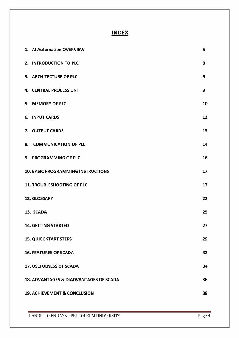
INDEX
1. AI Automation OVERVIEW 5
2. INTRODUCTION TO PLC 8
3. ARCHITECTURE OF PLC 9
4. CENTRAL PROCESS UNT 9
5. MEMORY OF PLC 10
6. INPUT CARDS 12
7. OUTPUT CARDS 13
8. COMMUNICATION OF PLC 14
9. PROGRAMMING OF PLC 16
10. BASIC PROGRAMMING INSTRUCTIONS 17
11. TROUBLESHOOTING OF PLC 17
12. GLOSSARY 22
13. SCADA 25
14. GETTING STARTED 27
15. QUICK START STEPS 29
16. FEATURES OF SCADA 32
17. USEFULNESS OF SCADA 34
18. ADVANTAGES & DIADVANTAGES OF SCADA 36
19. ACHIEVEMENT & CONCLUSION 38

PANDIT DEENDAYAL PETROLEUM UNIVERSITY Page 5
AI Automation OVERVIEW
AI Automation is a leading industrial automation house & ISO certified company in
Central India. The company has been in this business for more than 20 years. Company
initially has a vision to be in the field of Industrial Automation & Panel building. Starting
from infancy as small trading firm, over the years it now has its own panel building facility.
Under one roof, and with accumulated experience over the years, the company has
established itself not only as a leading industrial automation house but is also dealing in
Programmable Logic controller based system, SCADA & DAS, Servo systems, AC & DC Drive
systems, etc. The integration from Industrial automation to Technical Training has not been
accidental, but a natural fall out of the earlier step. The direction has been defined as they
complement each other and fill the gaps the technology has created. Thus, this well thought
move has resulted in simplification in use of technology and bridged the gap between the
technology and end-user.
Industrial automation is a demanding business and our focus has been customer
centric all through the years. We believe in service support and our Motto is “In service lies
success” The Quality has been a bench mark and every effort is made to ensure that the
product is made to International practices and standards.
As part of social commitment and identifying the need of technically qualified
personal the company has recently diversified in the field of Training of PLC, Drives, SCADA,
DAS & LT switchgears components and systems. We strongly believe in imparting our
esteemed Professional with latest knowledge and experiential learning with a focused vision
of “EMPOWERING WITH TECHNOLOGY".
The company has a wide assimilated experience in the field of automation and it has been a
constant endeavour to provide a committed service and support for the products and
systems so installed and commissioned. Some of the major systems commissioned by us are
stated below for reference.
FOOD PROCESSING APPLICATIONS
Automation of sterilizers for food processing application.
Cleaning in process applications.
Tank farm automation for chocolate industry.
PANDIT DEENDAYAL PETROLEUM UNIVERSITY Page 6
Panning applications for chocolate industry.
Bottling line automation.
Automation of fermentation tanks in bear factory.
Retrofitting of Packaging line.
LIFE SCIENCE APPLICATIONS
Panning applications for oral medicines
Autoclave applications.
Dry heat sterilizers.
Roller compactor applications.
HVAC applications.
Fluid bed drier application.
Mixer application.
Chiller automation.
Drying column application.
ENERGY & POWER
Synchronization of Diesel Generating sets in industry with DAS systems.
Auto mains failure panels for Industrial and communication industries.
Turbine bypasses systems.
Turbines start and stop applications along with protection & control.
Energy Management systems.
Breaker control systems and load management.

PANDIT DEENDAYAL PETROLEUM UNIVERSITY Page 7
CUSTOM DESIGNED APPLICATION
Motor Test Plant automation.
Solenoid Load characteristics testing systems.
Vacuum pressure Impregnation plant automation.
Automation of desk for Ultra high voltage lab. For transformer industry.
Painting oven automation in automobile industry.
Gas fired oven automation in automobile industry.
Overhead conveyor system for seven tank cleaning system in automobile
industry.
MACHINE TOOLS APPLICATIONS
Conductor cutting machine for Large Industrial motors
Sheet cutting & Flute rolling machine used for Transformer Radiator
manufacturers.
Cavern lathe automation has bed of 8 meters length.
Automation of vertical winding machine for transformer industry.
Forging press in automobile industry.
Vertical boring machine.
Vertical boring machine with bed diameter of 8 meters.
Retrofitting of PLC system on stacker reclaimer application.
Automation of ACSR conductor making machine.
Oven automation for electrical industry.

PANDIT DEENDAYAL PETROLEUM UNIVERSITY Page 8
INTRODUCTION TO PLC
A PLC is a user friendly microprocessor based specialized computer that is used to
control machines and process. It uses programmable memory to store instructions and
specific functions that include ON/OFF Control, timing, counting, sequencing, arithmetic and
data handling. PLC is designed for multiple inputs and output arrangements, extended
temperature ranges, immunity to electrical noise, and resistance to vibration and impact.
The first PLC system was introduced in late 60’s and early 70’s. It was developed to
offer the same functionality as the existing relay logic systems to the needs of an American
automobile manufacturing company. All the hard wiring, relay logics, timers, counters, drum
sequencers were replaced by PLC.
Early PLCs were designed to replace relay logic systems. These PLCs were
programmed in "ladder logic", which strongly resembles a schematic diagram of relay logic.
This program notation was chosen to reduce training demands for the existing technicians.
Early PLCs, up to the mid-1980s, were programmed using proprietary programming panels
or special-purpose programming terminals, which often had dedicated function keys
representing the various logical elements of PLC programs.
Programs were stored on cassette tape cartridges. Facilities for printing and
documentation were very minimal due to lack of memory capacity. Modern PLCs can be
programmed in a variety of ways, like ladder logic, functional block diagram, sequential flow
chart, etc. More recently, PLCs are programmed using application software on personal
computers. The computer is connected to the PLC through Ethernet, RS-232, RS-485 or RS-
422 cabling. The programming software allows entry and editing of the ladder-style logic.
Generally the software provides functions for debugging and troubleshooting the PLC
software.
The functionality of the PLC has evolved over the years to include sequential relay
control, motion control, process control, distributed control systems and networking.
The data handling, storage, processing power and communication capabilities of
some modern PLCs are approximately equivalent to desktop computers.
A person having knowledge in relay logic and digital logic can master major functions
of PLC. These functions might include coils, contacts, timers, counters etc.

PANDIT DEENDAYAL PETROLEUM UNIVERSITY Page 9
WHAT DOES ‘PLC’ MEAN?
A PLC (Programmable Logic Controllers) is an industrial computer used to monitor
inputs, and depending upon their state make decisions based on its program or logic, to
control (turn on/off) its outputs to automate a machine or a process.
ARCHITECTURE OF PLC
Following are the components of PLC:
Central Processing Unit (CPU)
Power Supply.
Input Section.
Output Section.
Programming Device
CENTRAL PROCESSING UNIT:
All the processors are designed to carry out arithmetic and logic operations.
Microprocessors are brains of every computer. Microprocessors are mainly classified on 2
factors:
1. Bit Size.
2. Clock Speed.
There are 4, 8, 16, 32 and 64-bit microprocessors, which manipulate data 4, 8, 16, 32
bits at a time respectively. The larger the bit size, more powerful the computer. Clock speed
determines how quickly a microprocessor executes instructions.
Microprocessor is a part of PLC CPU that receives, analyzes, processes and sends
data.
PANDIT DEENDAYAL PETROLEUM UNIVERSITY Page 10
It is a microprocessor based circuit. The CPU consists of following blocks:
1. Arithmetic Logic Unit.
2. Program Memory.
3. Process Image Memory.
4. Internal Timers and Counters.
5. Flags.
CPU performs the task necessary to fulfil the PLC functions. These tasks include
scanning, I/O bus traffic control, Program execution, peripheral and external device
communications, special functions or data handling execution and self diagnosis.
Regardless of the PLC size (small, medium, large) the processor and memory are in
the same unit. In large PLC’s, CPU contains just the processor and memory, whereas in small
PLC’s, CPU also contains Input Output interfaces along with processor and memory.
MEMORY OF PLC :
The memory of PLC is divided into two parts:
1. Program Memory.
2. Variable Memory.
Program Memory: The program memory contains the instructions to be executed and
cannot be changed while PLC is running.
Variable Memory: The variable memory can be change while the PLC is in RUN mode. (eg:
Data tables can be changed, accumulated value of timer and counter can be changed etc.)
Note: Some PLC’s allow on-line editing of program memory to make minor program
changes while the PLC is running)
In general, memory of PLC’s are often organized as files. There are basically two type of
files:
PANDIT DEENDAYAL PETROLEUM UNIVERSITY Page 11
1. Program Files: This file holds programs, such as ladder logic. Memory is organized into
blocks of up to 1000 elements in an array called a file. The PLC has a list of ’Main Tasks’ that
contain the main program(s) run each scan of the PLC. Additional programs can be created
that are called as subroutines. Valid program types include Ladder Logic, Structured Text,
Sequential Function Charts, and Function Block Diagrams.
2. Data Files: There are 8 data files by default, but additional data files can be added if
needed. This is where variable data is stored in the PLC to operate. The default 8 data files
are as follows:
a) O0 – Outputs
b) I1 – Inputs
c) S2 – Status
d) B3 – Bits
e) T4 – Timer
f) C5 – Counter
g) N7 – Integer
h) F8 – Float
RAM (RANDOM ACCESS MEMORY): Memories that has read and write capability. Since
RAM is volatile, it must have battery backup to retain or protect the stored programs.
ROM (Read Only Memory): Non-Volatile memory, do not require battery back up and
retains information or program when power is lost. Read only indicates that the information
stored in memory can be read only and cannot be changed.
EEPROM (Electrically Erasable Programmable Read Only Memory): It is a chip that can be
programmed using a standard programming device and can be erased by the proper signal
being applied to the erase pin.
Memory Size: Memory Size is usually expressed in “K” value: 2K, 4K, 16K and so on. K
actually stands for 1000 but represent 1024 because the numbering system used in PLC are
binary system. Different PLC’s have different memory size.
PANDIT DEENDAYAL PETROLEUM UNIVERSITY Page 12
Power Supply: The power supply gives the voltage required for electronics module (I/O
Modules, CPU, memory unit and peripheral devices) of the PLC from the line supply. It also
provides isolation necessary to protect the solid state devices from most high voltage line
spikes. As I/O is expanded, some PLC may require additional power supplies in order to
maintain proper power levels. Most of the PLC operate on 5V DC, or 9V DC.
INPUT CARDS
PLC operate by receiving input signals from external devices called field devices,
which include pushbuttons, limit switches, photo detectors and other such devices. Input
cards provide the electrical connection between field devices and the internal processor
unit of PLC. Field devices provide various types of inputs. These inputs differ in voltages and
in type of signal produced, such as an on and off, or a variable voltage. PLC manufacturers
make several types of input modules to interface field devices with the processor unit.
The Input cards perform the following tasks electronically:
1. It senses the presence or absence of an input signal at each of its input
terminals. The input signal tells what switch, sensor or other signal is ON or OFF
in the process being controlled.
2. It converts input signal for high or on to a DC level usable by modules
electronic circuits.
3. The input module carries out electronic isolation by electronically isolating the
input module output from its input.
A typical input module has 4, 6, 8, 12, 16, 32 terminals, plus common and safety ground
terminals. The isolation block protects the CPU from getting damaged from input
surge/circuit malfunction.
Basically three types of input are used:
1. Discrete or Digital Inputs.
2. Analog Inputs.
3. Specialized Input Modules.
PANDIT DEENDAYAL PETROLEUM UNIVERSITY Page 13
Discrete Inputs are either ON or OFF, OPEN or CLOSED (Limit Switches, Push Buttons, Relay
Coils, Solenoids, Indicator Lamps, Alarms etc.). These input modules come in wide range of
voltages for various applications, i.e 120V AC, 240V AC, 24V DC, 12-24V DC. Input cards
come with a wide range of input channels such as 4, 8, 16, 32 that determines the number
of field devices that can be connected to the module.
Analog Inputs are temperature, pressure, flow, level sensors, control valves etc. These input
modules are used to convert analog signals from analog devices that sense such variables as
temperature, light intensity, speed, pressure and convert to 16 bit binary, accomplished
with an analog to digital converter.
Specialized Input Modules are basically fast acting modules. These are used when process
requires fast acting sensors to respond to high speed applications. Encoders, high speed
sensors or proximity switches are some of the basic examples.
OUTPUT CARDS
Output modules can be for used for ac or dc devices such as solenoids, relays,
contractors, pilot lamps, and LED readouts. Output cards usually have from 6 to 32 output
points on a single module. The output device within the card provides the connection from
the user power supply to the load. Usually silicon controlled rectifiers (SCR), triac, or dry
contact relays are use for this purpose. Individual outputs are rated most often at 2 to 3
amperes. Output cards, like input cards have electrical isolation between the load being
connected and the PLC. Analog output cards are a special type of output modules that use
digital to analog conversion (D to A). The analog output module can take a value stored in a
12 bit file and convert it to an analog signal. Normally this signal is 0 -10 volts dc or 4 to 20
mA. This analog signal is often used in equipment such as motor operated valves and
pneumatic position control devices.
Basically three types of output are used:
1. Discrete or Digital Outputs
2. Analog Outputs
3. Specialized Output Modules
Discrete or Digital Outputs: These outputs module usually consists of a triac , however
some manufacturers also use SCR instead of a triac. When the processor decides that the

PANDIT DEENDAYAL PETROLEUM UNIVERSITY Page 14
output is to be turned ON, a signal is sent from the I/O rack and LED is turned on, the light
from the LED causes the phototransistor to conduct. This provides current for the gate of
the TRIAC. Optical Isolation protect the logic section from the line voltage of the output
device.
Discrete DC output modules use power transistor instead of the triac for the control
of output current. Power transistor has a quicker switching capability than the Triac,
therefore the response time for DC modules is faster than that of AC modules.
Analog Outputs: The analog output module changes the 16 bit binary value used by the
processor into analog signals using a digital or analog converter. These analog signals can be
used for speed controllers, signal amplifiers or valve positioners.
Specialized Output Modules: These are relay output modules which is used for low level
switching, multiplexing analog signals or for interfacing controls with different voltage
levels.
COMMUNICATION OF PLC
COMMUNICATIONS
PLCs have built in communications ports, usually 9-pin RS-232, but optionally EIA-
485 or Ethernet. Modbus, BACnet or DF1 is usually included as one of the communications
protocols. Other options include various field buses such as DeviceNet or Profibus. Other
communications protocols that may be used are listed in the List of automation protocols.
Most modern PLCs can communicate over a network to some other system, such as
a computer running a SCADA (Supervisory Control And Data Acquisition) system or web
browser.
PLCs used in larger I/O systems may have peer-to-peer (P2P) communication
between processors. This allows separate parts of a complex process to have individual
control while allowing the subsystems to co-ordinate over the communication link. These
communication links are also often used for HMI devices such as keypads or PC-type
workstations.

PANDIT DEENDAYAL PETROLEUM UNIVERSITY Page 15
LIST OF AUTOMATION PROTOCOLS:
DF-1
FOUNDATION fieldbus - H1 & HSE
Profibus - by PROFIBUS International.
PROFINET IO
CC-Link Industrial Networks - Supported by the CLPA
CIP (Common Industrial Protocol) - Can be treated as application layer common
to DeviceNet, CompoNet, ControlNet and EtherNet/IP
Controller Area Network utilised in many network implementations, including
CANopen and DeviceNet
ControlNet - an implementation of CIP, originally by Allen-Bradley
DeviceNet- an implementation of CIP, originally by Allen-Bradley
DirectNet - Koyo / Automation Direct proprietary, yet documented PLC interface
EtherNet/IP - IP stands for "Industrial Protocol". An implementation of CIP,
originally created by Rockwell Automation
Ethernet Powerlink- an open protocol managed by the Ethernet POWERLINK
Standardization Group (EPSG).
EtherCAT
Interbus, Phoenix Contact's protocol for communication over serial links, now
part of PROFINET IO
HART Protocol
Modbus RTU or ASCII or TCP
Modbus Plus
Modbus PEMEX
Ethernet Global Data (EGD) - GE Fanuc PLCs (see also SRTP)
FINS, Omron's protocol for communication over several networks, including
ethernet.
HostLink Protocol, Omron's protocol for communication over serial links.
MECHATROLINK - open protocol originally developed by Yaskawa.
MelsecNet, supported by Mitsubishi Electric.
Optomux - Serial (RS-422/485) network protocol originally developed by Opto 22
in 1982. The protocol was openly documented and over time used for industrial
automation applications.
Honeywell SDS - Smart Distributed System - Originally developed by Honeywell.
Currently supported by Holjeron.
SERCOS interface, Open Protocol for hard real-time control of motion and I/O
SERCOS III, Ethernet-based version of SERCOS real-time interface standard
GE SRTP - GE Fanuc PLCs
Sinec H1- Siemens

PANDIT DEENDAYAL PETROLEUM UNIVERSITY Page 16
SynqNet - Danaher
TTEthernet - TTTech
PieP - An Open Fieldbus Protocol
PROGRAMMING OF PLC
A programming device is needed to enter, modify and troubleshoot the PLC program
or to check the condition of the processor. Once the program has been installed, entered
and the PLC is running, the programming device may be disconnected. Three types of
programming device are generally used:
1. Hand held (smaller, cheaper, portable but limited display capability and few functions)
2. Dedicated Desktop (User – Friendly , designed for industrial use, portable but costly,
limited PLC’s can be programmed, limited documentation and limited graphics capability)
3. Personal computer with software available for all major brands of PLC’s. The PC today is
most common programming device. It can store programs on floppy disc and hard disc.
These software can easily be updated by the latest firmware so that we can have some
more additional features.
4. Programming software used for Allen Bradley PLC programming is RSLOGIX500 and
RSLOGIX5000.
5. Software used for communication with the PLC is RSLINX.
6. PLC programs are typically written in a special application on a personal computer, then
downloaded by a direct-connection cable or over a network to the PLC. The program is
stored in the PLC either in battery-backed-up RAM or some other non volatile flash memory.
Often, a single PLC can be programmed to replace thousands of relay
Under the IEC 61131-3 standard, PLCs can be programmed using standards based
programming languages. A graphical programming notation called Sequential Function
Charts is available on certain programmable controllers. Initially most PLCs utilized Ladder
Logic Diagram Programming, a model which emulated electromechanical control panel
devices (such as the contact and coils of relays) which PLCs replaced. This model remains
common today.

PANDIT DEENDAYAL PETROLEUM UNIVERSITY Page 17
IEC 61131-3 currently defines five programming languages for programmable
Control systems: FBD (Function block diagram), LD (Ladder diagram), ST (Structured text,
similar to the Pascal programming language), IL (Instruction list, similar to assembly
language) and SFC (Sequential function chart). These techniques emphasize logical
organization of operations. While the fundamental concepts of PLC programming are
common to all manufacturers, differences in I/O addressing, memory organization and
instruction sets mean that PLC programs are never perfectly interchangeable between
different makers. Even within the same product line of a single manufacturer, different
models may not be directly compatible.
BASIC PROGRAMMING INSTRUCTIONS
First of all here we will study about understanding and using logic diagram. Wiring
diagram shows the circuit wiring and its associated devices (relays, timers, motor relays,
switches , etc.). This type of diagram assists us in locating components and shows how a
circuit is actually wired.
Ladder logic is a programming language that represents a program by a graphical diagram
based on the circuit diagrams of relay logic hardware. It is primarily used to develop
software for Programmable Logic Controllers (PLCs) used in industrial control applications.
The name is based on the observation that programs in this language resemble ladders, with
two vertical rails and a series of horizontal rungs between them.
TROUBLESHOOTING OF PLC
Careful start up procedures is necessary to prevent damage to the driven equipment
and PLC or more importantly injury to personnel. Prior to beginning a system start up
procedure, it is important to check and verify that the system has been installed according
to the manufacturers specifications and that the installation meets national codes. Special
attention should be given to system grounding.
Learn how to troubleshoot and diagnose PLC's with this procedure and how to
identify the PLC problem areas.
1. Identify where the PLC problem might be with certain Inputs or outputs etc.
2. Check to ensure main PLC power is being applied (120vac or 24vdc) many
times there is a main power LED on the PLC to indicate so. Also check that it is
the correct voltage being applied.

PANDIT DEENDAYAL PETROLEUM UNIVERSITY Page 18
3. Check the 24VDC power supply that may be either provided internally from
the PLC itself or by an external power supply. Also check no primary fuses are
blown.
4. Check the 120VAC supply or transformer is outputting correct voltage and no
fuses are blown. This is often used for hydraulic solenoid coils and such.
5. Look for the area of the cell or sensors and switches located in the problem
area. Such as a tool changer, pallet changer or magazine area. Look through the
electrical prints for the possible proxes or devices that may be faulty.
6. Check each input LED goes on, on the PLC or on the internal control
diagnostics. Manually make each of the switches. Put the machine in Emergency
STOP to avoid any unexpected movements. But still be careful as some ladders
are not written fully safe. Remember proxes typically fail to, on state so make
sure they are not on when they are not supposed to be as well.
7. Check the inputs on the machine or PLC diagnostics as you make and break
them. If these are all working correctly move on to checking the outputs below.
Otherwise test that power is coming back into the PLC inputs with a meter.
8. At this point it may be necessary to actuate the machine either by an M-code
if it is a CNC or if it is a PLC direct then run the functions you are trying to
perform.
9. Determine possible solenoids or outputs that should be turning on for each
condition and monitor when actuated. Now check the output LED's or Y
addresses to see if plc or control is outputting them.
10. If the outputs are being turned on by watching the diagnostics or LED's.
Verify with a meter the proper voltage is coming out of the PLC and verify the
proper voltage is at the solenoid. Many PLC outputs often go through a relay of
some sort to change over to 120 volts. Make sure you check the voltage at the
relay coil as well as the supply being but to the dry set of contacts on the relay.
Make sure the relay switches when the PLC output is turned on.
11. Many times these relay boards will have a relay go, bad or have a device
such as a solenoid that shorts out to ground causing the relay contact to burn
up. There are also sometimes fuses in the circuit as well that may need to be
checked.

PANDIT DEENDAYAL PETROLEUM UNIVERSITY Page 19
12. If the relay contact is found to be bad. Check with your meter and the power
off to ground from the circuit that may be shorted. If its less then 40 ohms or so
you most likely have a short to ground. Find the short or bad coil and repair.
Then sometimes another relay may be swapped out that was not being used on
the board Many times you have to unsolder and resolder in the bad relays place
13. Some PLC's if they are for automation or external fixtures sometimes have a
reset on them to clear and major alarms inside the PLC itself. But you generally
would have a complete shut down of PLC functions if this were the case.
Before applying power to PLC, following is to be ensured:
1. Verify that incoming power matches the jumper selected voltage setting of
the power supply.
2. Verify that the hardwired safety circuit or other emergency stop device has
been installed and is in open position.
3. Check all the power and communication cables to ensure that the connector
pins are straight and not bent.
4. Ensure that all the I/O modules are securely held in I/O rack.
5. Ensure that PLC is in program mode.
Apply power and observe processor indicator light for proper indication. When power is
applied , the power supply should provide the necessary DC voltage for the processor and
I/O rack. If proper voltage is present , the input indicator LED’s of the input module will
function. Any input that is closed or ON will have an illuminated LED.
Testing inputs: Each input device can be manipulated to obtain open and closed contact
conditions. Each time an input device is closed the corresponding LED on the input module
should illuminate. Failure of a LED to illuminate indicates:
Improper input device operation.
Incomplete or incorrect wiring; check that input device is wired.
Loss of power to input device.
PANDIT DEENDAYAL PETROLEUM UNIVERSITY Page 20
Defective LED or Input Module.
Testing Outputs: before testing output devices, it must be determined which devices can be
safely activated and which devices should be disconnected from the power source. For the
outputs that can be safely started, be sure equipment is in the start up position, properly
lubricated and ready to run.
There are two methods used to test output devices. The first method uses a push
button or other convenient input device that is a part of control panel. The push button is
programmed to energize each output, one at a time.
The second method uses the force function of the PLC given in the software, to
energize outputs, one at a time. This allows user to turn an output device ON and OFF
without using a push button or other contacts.
If the output module indicating LED is illuminated but a connected output device
does not energize, check the following:
Wiring to the output device.
Operation of the output device.
Proper potential to the output device.
Output device wired to correct output module and proper terminal.
Final System Checkout after all input and output circuits have been tested and verified,
reconnect any output loads (motors, solenoids etc) that were previously disconnected. For
final system checkout following steps should apply:
1. Place the processor in the program mode.
2. Clear the memory of any previous rung used for testing.
3. Using a programming device, enter the program (ladder diagram) into the
memory.
4. Place the processor in the test or disable output module, depending on the
PLC and verify correctness of the program.

PANDIT DEENDAYAL PETROLEUM UNIVERSITY Page 21
5. Once the circuit operation has been verified in the teat or disable output
mode, the processor can be placed in the run mode for final verification.
6. Once the circuit is fully tested, and the machine or process is running correctly
it is recommended that a copy of the program should be made.
Troubleshooting: To be successful troubleshooter, the engineers must use a systematic
approach. Systematic approach should consist of the following steps:
1. Symptom recognition.
2. Isolate the problem.
3. Corrective action.
The engineer should be aware of how the system normally functions if he or she
expects to successfully troubleshoot the system. Although PLC cannot talk, it can
communicate in various ways to show what the problem is. There are status lights on the
processor, power supply and I/O racks that indicate proper operation, as well as status lights
alert the troubleshooter to the problem. The status lights of a typical processor with built in
power supplies indicates:
1. DC Power ON: If this LED is not lit, there is a fault in the DC power supply. Check the
power supply fuse or the incoming power.
2. Mode: This indicates which operating mode the processor is in (Run, test, program etc.)
The fault may simply be due to the fact that key switch is in the wrong position.
3. Processor Fault: When this status light is on, it indicates a fault within the processor. This
is a major fault, and requires changing the processor module. Replace only one module at a
time. If the first module does not correct the problem, reinstall the original module and then
replace the second module. If replacing the second module does not clear the problem,
replace both the modules.
4. I/O Fault: This indicates a communication error between the processor and the I/O rack.
Check that the communication cable is fully inserted into their sockets and look for error
codes or fault messages for further diagnostic assistance.
5. Standby battery low: When this LED is illuminated, the RAM backup batteries are low and
need to be replaced. Although this is not a fault condition, failure to replace batteries results
in losing the program when the system is shut down or a power failure occurs.
PANDIT DEENDAYAL PETROLEUM UNIVERSITY Page 22
Output modules have LED indicators that illuminate when each of the output circuits
are turned ON. If the LED is lit for the location of the solenoid, it indicates that the problem
is not with the output module, but with the circuit from the module to the solenoid or with
the solenoid itself.
GLOSSARY
Triac: TRIAC, from Triode for Alternating Current, is a genericized tradename for an
electronic component which can conduct current in either direction when it is triggered
(turned on), and is formally called a bidirectional triode thyristor or bilateral triode
thyristor. It is used as an electronic switch to turn output devices ON or OFF. The triac itself
is the equivalent of two SCR’s in reverse parallel connection with a common gate. The gate
controls the switching state (ON or OFF) of the device. Once the signal is applied and the
break over voltage point is reached on the gate (normally 1 to 3V), the triac freely conducts
in either direction, completing the path for the current flow to the output device.
Interposing Relay: These are used to control loads larger than the rating of an individual
output circuit. A standard control relay, which has a small shield current value, is connected
to the output module. The contacts of control relay, which are generally rated at 10 amps
can be used to control larger loads.
Address: A location in processor memory.
Baud Rate: A unit of data transmission speed equal to the number of characters (letters,
numbers, symbols) per seconds.
Bite: A sequence of binary digits usually operated upon as a unit (normally eight bits)
Backplane: A printed circuit board, located in the back of a chassis, that contains a data bus,
power bus and mating connectors for modules that will be inserted into the chasis.
Backup: A device or system that is kept on hand to replace a device or a system that fails.
Battery Backup: A battery or set of batteries that will provide power to the processor’s
memory in the event of a power outage.
Baud: (1) The reciprocal of the shortest pulse width in a data communication stream. (2)
The number of binary bits transmitted per second during a serial data Transmission

PANDIT DEENDAYAL PETROLEUM UNIVERSITY Page 23
Block: A group of words transmitted as a unit.
Block diagram: A schematic drawing.
Branch: A parallel logic path within a rung.
Channel: A designated path for a signal.
Chassis: A hardware assembly that houses PLC devices, such as I/O modules, adapter
modules, processor modules, power supplies, and processors.
Data table: The part of a processor’s memory, containing I/O values and files, where data is
monitored, manipulated, and changed for control purposes
Data Manipulation: The process of altering or exchanging data between storage words.
Duplex: A means of two-data communication.
Digital-to-analog converter (D/A): A device that translates binary numbers from a processor
into analog signals that field devices can understand
Electrical Noise: Noise or voltage spikes that are generated whenever inductive loads, such
as solenoids, relays, motor starters are operated.
Electrical optical Isolator: A device that couples different voltage levels using a light source
and detector In the same package. It is used to provide electrical isolation between line
voltage input and the output circuitry and the processor.
Fifo: First in first out. A reference to the way that information is stored and removed from a
file or register.
Force: A mode of operation or instruction that allows the operator to control the state of an
input or output device.
Full Duplex: A mode of communication in which data may be simultaneously transmitted
and received by both ends. (sender / receiver)
Half Duplex: A mode of transmission capable of communicating in two direction, but only in
one direction at a time such as walkie – talkie.

PANDIT DEENDAYAL PETROLEUM UNIVERSITY Page 24
Holding Register: A register or file that holds a value or values for comparison or for use in
user program.
Image Table: An area in PLC memory dedicated to I/O data. During every I/O scan each
input controls a bit in the input image table and each out is controlled by a bit in the output
image table.
Instruction: A command or order that causes a PLC to perform certain operations.
Interposing Relay: A relay that is added to a PLC circuit to handle current values larger than
can be handled by one terminal of an output module.

PANDIT DEENDAYAL PETROLEUM UNIVERSITY Page 25
SUPERVISORY CONTROL AND DATA ACCQUISITION SYSTEM
(SCADA)
SCADA (SUPERVISORY CONTROL AND DATA ACQUISITION) generally refers to
industrial control systems: computer systems that monitor and control industrial,
infrastructure, or facility-based processes, as described below:
Industrial processes include those of manufacturing, production, power
generation, fabrication, and refining, and may run in continuous, batch,
repetitive, or discrete modes.
Infrastructure processes may be public or private, and include water treatment
and distribution, wastewater collection and treatment, oil and gas pipelines,
electrical power transmission and distribution, Wind farms, civil defense siren
systems, and large communication systems.
Facility processes occur both in public facilities and private ones, including
buildings, airports, ships, and space stations. They monitor and control HVAC,
access, and energy consumption.
COMMON SYSTEM COMPONENTS
A SCADA System usually consists of the following subsystems:
A Human-Machine Interface or HMI is the apparatus which presents process
data to a human operator, and through this, the human operator monitors and
controls the process.
A supervisory (computer) system, gathering (acquiring) data on the process and
sending commands (control) to the process.
Remote Terminal Units (RTUs) connecting to sensors in the process, converting
sensor signals to digital data and sending digital data to the supervisory system.
Programmable Logic Controller (PLCs) used as field devices because they are
more economical, versatile, flexible, and configurable than special-purpose
RTUs.
Communication infrastructure connecting the supervisory system to the Remote
Terminal Units.
PANDIT DEENDAYAL PETROLEUM UNIVERSITY Page 26
There is, in several industries, considerable confusion over the differences between
SCADA systems and distributed control systems (DCS). Generally speaking, a SCADA system
always refers to a system that coordinates, but does not control processes in real time. The
discussion on real-time control is muddied somewhat by newer telecommunications
technology, enabling reliable, low latency, high speed communications over wide areas.
Most differences between SCADA and DCS are culturally determined and can usually be
ignored. As communication infrastructures with higher capacity become available, the
difference between SCADA and DCS will fade.
Summary: 1. DCS is process oriented, while SCADA is data acquisition oriented.
2. DCS is process driven, while SCADA is event driven.
3. DCS is commonly used to handle operations on a single locale, while
SCADA is preferred for applications that are spread over a wide geographic location.
4. DCS operator stations are always connected to its I/O, while SCADA is
expected to operate despite failure of field communications.
SYSTEMS CONCEPTS
The term SCADA usually refers to centralized systems which monitor and control
entire sites, or complexes of systems spread out over large areas (anything from an
industrial plant to a nation). Most control actions are performed automatically by Remote
Terminal Units ("RTUs") or by Programmable Logic Controllers ("PLCs"). Host control
functions are usually restricted to basic overriding or supervisory level intervention. For
example, a PLC may control the flow of cooling water through part of an industrial process,
but the SCADA system may allow operators to change the set points for the flow, and
enable alarm conditions, such as loss of flow and high temperature, to be displayed and
recorded. The feedback control loop passes through the RTU or PLC, while the SCADA
system monitors the overall performance of the loop.
PANDIT DEENDAYAL PETROLEUM UNIVERSITY Page 27
GETTING STARTED:
WELCOME TO RSVIEW32
RSView32 is Windows based software for developing and running human machine
interface applications. Designed for use in Microsoft Windows Server 2003, Windows XP and
Windows 2000, RSView32 gives you all the tools you need to create and run effective
monitoring and supervisory control applications. RSView32 Works contains both
development and runtime software. Use this software to develop and run RSView32
applications.RSView32 Runtime contains only runtime software. Use this software to run
applications developed in RSView32 Work
RSVIEW32 WORKS
RSView32 Works contains editors for creating a complete human-machine interface
application and contains software for running the applications you create. Use the editors to
create applications that are as simple or as sophisticated as you need. When you have
finished developing your application, switch to run mode or use RSView32 Runtime (which is
included with RSView32 Works and uses less memory), and run your application.
Getting Results with RSView32
With RSView32, you can use the RSView32 ActiveX and OLE container capabilities to
take advantage of advanced technology. For example, embed Visual Basic or other ActiveX
components in RSView32 graphic displays to extend the capabilities of RSView32. create
and edit displays with tools native to the Microsoft programs you are using now. With
sophisticated object-oriented graphics and animation, plus simple dragand- drop and cut-
and-paste techniques, application configuration is simplified.
Use the RSView32 Object Model and VBA to share data with other .Windows
programs such as Microsoft Access and Microsoft SQL Server, interoperate with other
Windows programs such as Microsoft Excel, and customize and extend RSView32 to fit your
unique needs use graphics from the RSView32 graphic libraries or import files from other
drawing packages such as Corel DRAW, and Adobe Photoshop develop your application
quickly using RSView32 productivity tools such as the Project Documentor, Project
Transport Wizard, Command Wizard, Tag Browser, and Object Smart Path (OSP).
Use the Graphic Display editor to create graphical displays of your process.
PANDIT DEENDAYAL PETROLEUM UNIVERSITY Page 28
Getting started and avoid entering information twice. Import an Allen-Bradley PLC or
SLC database with the PLC Database Browser. Or browse for tags in third-party OPC servers.
To import Control Logix tags, use the Logix 5000 Tag.
IMPORT UTILITY:
Use the RSView32 alarm notification capability to monitor process incidents with
multiple levels of severity. Create multiple alarm summaries to provide specific alarm data
rather than viewing the alarms for the entire system. Create trends that show process
variables plotted against time. Display realtime or historical data with up to 16 pens (tags) in
each trend. Log data simultaneously to multiple log files or remote ODBC databases to
provide various records of production data. Bring the logged data directly into other third-
party programs such as Microsoft Excel and Crystal Reports without converting files. Lock
users into the RSView32 application by disabling Windows keys use the electronic signature
verification and authorization feature to verify the identity of the operator before an action
can occur. This feature allows you to meet the security standards required for regulated
manufacturing applications, for example those required for US Government 21 CFR Part 11
compliance

PANDIT DEENDAYAL PETROLEUM UNIVERSITY Page 29
QUICK START STEPS
The following steps explain how to get up and running with RSView32. To work with
RSView32, you must complete steps 1 and 2 in the specified order. The other steps can be
completed in any order.
STEP 1: CREATE A PROJECT
Create the project that you will run. A project is a folder on your hard disk that
contain, among other things, the RSView32 project file (*.RSV).
STEP 2: SET UP COMMUNICATIONS IN RSVIEW32
Establish communications between RSView32 and the hardware and devices you are
using. For communications with most Allen-Bradley devices as well as SoftLogix5 devices,
RSView32 uses a direct driver connection. RSView32 uses the drivers in RSLinx. To set up
direct driver communications to devices, set up a channel and node and, optionally, a scan
class.For communications with other local and remote devices, RSView32 uses OPC or DDE
connections. OPC (OLE for process control) allows RSView32 to act as a client or server,
allowing peer-to-peer communication between different RSView32 stations, as well as other
OPC servers. RSView32 uses standard or high-speed AdvanceDDE™ (dynamic data exchange)
data formats to communicate with DDE servers and DDE clients such as Microsoft
Excel.Getting.
To set up OPC or DDE communications, set up an OPC or DDE node.
STEP 3: CREATE GRAPHIC DISPLAYS, TRENDS, AND ALARM SUMMARIES
Create graphic displays that represent your process. Build your graphic displays in a
variety of ways:
Use the RSView32 drawing tools to create graphic objects and text. You can
create simple objects such as ellipses and rectangles, or create more complex
objects such as trends and alarm summaries. You can also embed ActiveX
objects. drag and drop ready-made objects from the RSView32 libraries into a
display.
Import objects or entire images that have already been created in other drawing
packages such as CorelDRAW. Create graphic displays, trends, and alarm
summaries in the Graphic Display editor.
PANDIT DEENDAYAL PETROLEUM UNIVERSITY Page 30
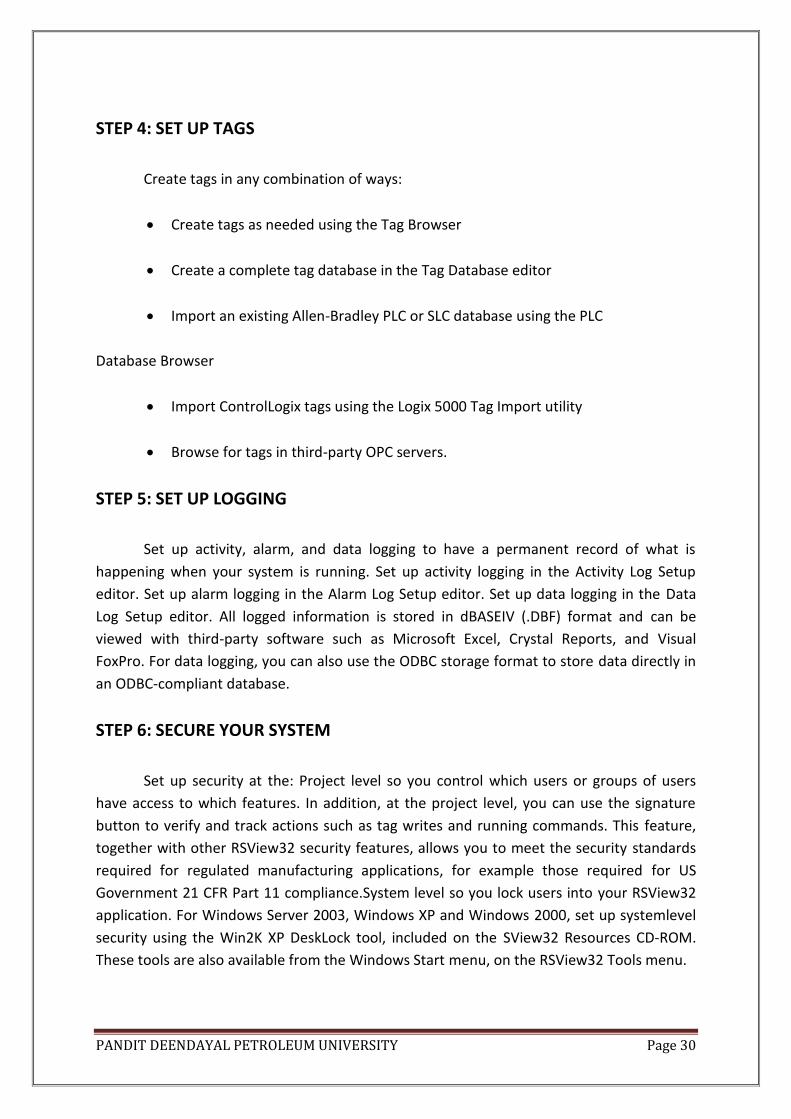
STEP 4: SET UP TAGS
Create tags in any combination of ways:
Create tags as needed using the Tag Browser
Create a complete tag database in the Tag Database editor
Import an existing Allen-Bradley PLC or SLC database using the PLC
Database Browser
Import ControlLogix tags using the Logix 5000 Tag Import utility
Browse for tags in third-party OPC servers.
STEP 5: SET UP LOGGING
Set up activity, alarm, and data logging to have a permanent record of what is
happening when your system is running. Set up activity logging in the Activity Log Setup
editor. Set up alarm logging in the Alarm Log Setup editor. Set up data logging in the Data
Log Setup editor. All logged information is stored in dBASEIV (.DBF) format and can be
viewed with third-party software such as Microsoft Excel, Crystal Reports, and Visual
FoxPro. For data logging, you can also use the ODBC storage format to store data directly in
an ODBC-compliant database.
STEP 6: SECURE YOUR SYSTEM
Set up security at the: Project level so you control which users or groups of users
have access to which features. In addition, at the project level, you can use the signature
button to verify and track actions such as tag writes and running commands. This feature,
together with other RSView32 security features, allows you to meet the security standards
required for regulated manufacturing applications, for example those required for US
Government 21 CFR Part 11 compliance.System level so you lock users into your RSView32
application. For Windows Server 2003, Windows XP and Windows 2000, set up systemlevel
security using the Win2K XP DeskLock tool, included on the SView32 Resources CD-ROM.
These tools are also available from the Windows Start menu, on the RSView32 Tools menu.

PANDIT DEENDAYAL PETROLEUM UNIVERSITY Page 31
STEP7: CUSTOMIZE AND INTEGRATE RSVIEW32 WITH OTHER APPLICATIONS.
Use the RSView32 Object Model with Visual Basic or Visual Basic for Applications
(VBA) to customize and extend the capabilities of RSView32, and to integrate RSView32 with
other applications. Some ways you might do this include:
Networking. If your RSView32 application includes logic to switch between
redundant PLCs, you can use the RSView32 Object Model with Visual Basic or
VBA to include node information in a graphic display. This lets you indicate the
station number of the active PLC, and allows an operator to take corrective
action if a PLC goes offline.
Tag management. Write a VBA program to modify alarm information, such as
thresholds and severities, each time a different product is manufactured on a
multipurpose production line.
User and access control. Within a VBA program, check the security code for an
engineer or operator, and then allow the VBA program to change alarm
configurations, or display only status information, depending on the person’s
level of access.
Alarms. Write your own alarm detection algorithms using Visual Basic or VBA,
and then add alarm events to RSView32, to respond to your algorithms for
annunciation, logging, printing, and for display in alarm summaries.
Data logging. Use the RSView32 Object Model and other object models to collect
data from multiple sources, such as expert systems, self-tuning PID algorithms,
and tags, and then view the data in trends. You can also filter data for your own
needs by reading from one data log model, and then writing to another data log
model.
Activity logging. Use the RSView32 Object Model with Visual Basic or VBA to log
specific operator actions for tracking and documentation purposes. Write
activity information to customized categories for sorting and analysis.
Application interfacing. Use the RSView32 Object Model to interface with the
object models of other applications. For example, you can use the Microsoft
Excel object model to create a report in a worksheet, to add statistical formulas
for analysis, and then print the report

PANDIT DEENDAYAL PETROLEUM UNIVERSITY Page 32
FEATURES OF SCADA:
ALARMS: They have a very critical role in automation. Generally you have alarm states for
each input/outputs, like your temperature should not cross 80 deg or should not be lower
than 60. So if the parameter goes in alarm state the operator should be intimated with the
alarm. Most of the scada software support four types of alarms like Low Low(LOLO),
Low(LO), High(HI), High High(HIHI). Alarms are the most important part of control
application because the operator must know instantly when something goes wrong. It is
often equally important to have a record of alarm and whether an alarm was acknowledged
or not. An alarm occurs when something goes wrong. It can signal that a device or process
has ceased operating within acceptable, predefined limits or it can indicate breakdown,
wear or process malfunction.
REAL TIME AND HISTORICAL TREND: The trend play very important role in the
process operation. If your batch fails or the plant trips, you can simply go to the historical
trend data and do the analysis. You can have better look of the parameters through the
trend.
Eg: We commission a SCADA System for Acid regeneration plant where the plant has
to be operated on 850-degrees temperature. If the operator operates the plant at 900
degree you can imagine how much additional LPG, he is putting into the reactor. Again what
will happen to the bricks of the reactor. So the production manager’s first job will be to go
through the trends how the operators are operating the plant. Even when the plant trips
there are more than 25 probable reasons for the same but if you go through the historical
trends, it is very easy to identify the problems.
RECIPE MANAGEMENT: It is an additional feature. Some SCADA software support it,
some do not. Most of the plants are manufacturing multi products. When you have different
products to manufacture, you just have to load the recipe of the particular product.
SECURITY: Security is one facility people generally look for. You can allocate certain
facilities or features to the operator , process people, engineering dept. and maintenance
dept. For example operators should only operate the system, he should not be able to
change the application. The engineers should have access to changing the application
developed.
DEVICE CONNECTIVITY: You will find there are hundreds of automation h/w
manufacturer like Modicon, Siemens, Allen Bradley, Yokogawa, ABB. Everybody has there
own way of communication or we can say that they have there own communication
protocol. SCADA software should have connectivity to the different h/w in the automation.

PANDIT DEENDAYAL PETROLEUM UNIVERSITY Page 33
It should not happen that for Modicon I am buying one s/w and for Siemens another one.
The software like ASPIC or WONDERWARE has connectivity to almost all hardware used in
automation.
DATABASE CONNECTIVITY: Nowdays information plays a very important role in any
business. Most manufacturing units go for Enterprise Resource Planning (ERP) or
Management Information System (MIS).
DYNAMIC PROCESS GRAPHIC: Mimics developed in SCADA software should resemble
the process Mimic. Scada have a very good library and symbols so that we can develop the
mimic as per our requirement. Once the operator sees the mimic he should know what is
going on in the plant.

PANDIT DEENDAYAL PETROLEUM UNIVERSITY Page 34
USEFULNESS OF SCADA:
PRODUCTION DEPARTMENT:
1. Real Time Production Status: Manufacturing status is updated in real time in
direct communication to operator and control device.
2. Production Schedules: Production schedule can be viewed and updated
directly.
3. Production information management: Production specific information is
distributed to all.
QUALITY DEPARTMENT:
1. Data Integrity and quality control is improved by using a common interface.
2. It is an open platform for statistical analysis.
3. Consolidation of manufacturing and lab data.
MAINTENANCE DEPARTMENT:
1. Improved Troubleshooting and de-bugging: direct connection to wide variety
of devices, displays improves trouble shooting reduces diagnostic/debugging
time.
2. Plant can be viewed remotely. Notification can indulge pagers, e-mails and
phones.
3. Co-ordination between maintenance and management reduces unscheduled
downtime.
ENTERPRISE INFORMATION:
1. Corporate Information and real time production data can be gathered and
viewed from anywhere within your operations.
2. User specific information ensures better informed decisions.

PANDIT DEENDAYAL PETROLEUM UNIVERSITY Page 35
3. Data Exchange with standard databases and enterprise systems provides
integrated information solutions.
ENGINEERING DEPARTMENT:
1. Integrated Automation Solutions reduce design and configuration time.
2. Common configuration platform offers flexibility for constant configuration in
all areas.
3. Capable of connecting to wide variety of systems. Reduces start up time and
system training with industry proven open interfaces.
MANUFACTURING DEPARTMENT:
1. Unscheduled down time is reduced due swift alarm detection and event
driven information.
2. Makes operations easier and more repeatable with its real time functionality.
3. Secured real time operations are maintained with windows.
PANDIT DEENDAYAL PETROLEUM UNIVERSITY Page 36
ADVANTAGES OF SCADA
1. CHEAPER
2. CONTINIOUS OPERATION
3. RELAIBLE
4. IMPROVES MAINTENANCE, OPERATION AND CUSTOMER SERVICE.
5. FEW OPERATORS CONTROL LARGE NUMBER OF INDIVIDUAL ASSETS.
6. PROVIDE RAPID RESPONSE TO EMERGENCIES.
DISADVANTAGES OF SCADA
1. TROUBLED ALARMS
2. LACK OF TRAINED MANPOWER.
3. INITIAL CAPITAL INVESTEMENT.
SOME OF THE SCADA MANUFACTURERS AND NAME OF THE
SOFTWARE:
1. WONDERWARE – INTOUCH
2. ALLEN BRADLEY – RSVIEW32
3. SIEMENS – WINCC
4. MODICON – MORIECON
5. GE FANUC - CIMPLICITY
6. KPIT – ASHTRA

PANDIT DEENDAYAL PETROLEUM UNIVERSITY Page 37
BENEFITS OF SCADA
1. Long Distance Monitoring
2. Long Distance Training.
3. Data Management (engineering and operations)
4. Automated operations with real time controls.
CONCLUSION
SCADA is a control system with:
1. More Interfaces and efficient storage.
2. More record or device oriented configuration.
3. System wide configuration tools are needed.
4. Less expensive than DCS but offer different functionality than DCS.
PANDIT DEENDAYAL PETROLEUM UNIVERSITY Page 38
ACHIEVEMENT
The one month training at AI Automation, Bhopal was a great learning experience as
I had very little knowledge about the Programming Logic Controllers (PLC) and Supervisory
Control And Data Acquisition System (SCADA). With the help of this I was able to understand
why is there a need of Control System in all the leading sectors of Industries and Companies
all around the world.
It was a very wonderful experience for me to increase my knowledge of what I had
learned in the College. It felt great to solve problem based on PLC and SCADA. Also, some of
the problems were directly related to the Industrial Sector.
With the help of this Industrial Training my confidence of working in the Automation
Sector has boosted up. It was a very fruitful internship for me as I got a glimpse of the
Automation Sector and what all happens in it.
CONCLUSION
The one month internship at AI Automation, Bhopal was a great learning
experience and I would like to thank the college training and placement cell through which I
had applied for the Internship. Getting to know the industrial working environment in such a
company was also very helpful. The people there were very helpful and helped us in
understanding any concept.