ahu plusairplus.com.tr/uploads/59f962a3725c4.pdf · ahu plus dx dx air handling units ... - having...
TRANSCRIPT
AHU PlusDX Air Handling Units

AHU Plus DXDX Air Handling Units
AHUPlusDX-TH: DX Air Hadling Unit with 100% Fresh AirAHUPlusDX -IGK: DX Air Hadling Unit with 100% Fresh Air and Heat Recovery
AHUPlusDX-KH: DX Air Handling Unit with Mixing Section
40
Section Construction Structure
DX Air Handling Units are formed from required modular sections according to need.
Frame of modular sections of our Air Handling Units are manufactured from natural aluminum anodized profile and plastic corner connection elements. Thickness of section panels are 42 mm, outer wall is electrostatic powder coated and inner wall is manufactured from galvanized sheet.
AHUPlus DX Air Handling Units are indispensable at central ventilation and ambient air conditioning applications due to its high efficiency and energy saving provided by its 70 kg/m³ dense Rockwool filled panels, modern frame structure, statically and dynamically balanced, quiet and efficient plug fans.
Our electrical motors are 380V-50Hz as standard. High efficient plug fans with EC motor can also be used on customer demand.
All double-walled panels are mounted to the aluminum frame by special torch tipped M6 nuts. Double-walled rigid standard inspection doors have gapless rigid hinge,
lock mechanism that will not create protrusion inside of the section and will not allow air leakage.
There are 180 mm high, full-length chassis feet manufactured from 2 or 3 mm galvanized sheet. There are slots and holes at the corner of the chassis feet for handling it with crane or forklift.
All of the holes required for automation (differential pressure switch, NTC temperature sensor, frost thermostat etc.) are opened on DX Air Handling Unit at production stage. Motor connection cables are taken to the junction box. On demand, the unit can be delivered as all automation placed, adjusted and collected at the panel.
Section connection elements are manufactured from aluminum alloy material. They have high structural strength for connecting the section from outside. The total number of use between sections varies according to the size of the model.
There is interior lighting and sight glass at fan and filter sections. Thanks to these accessories, sections can be checked without disabling the system.

41
DX coil means cooling the air by loading the heat taken from the air passing through the evaporator to refrigerant with the help of compressor.
To simply describe the system, a direct expansion-cooling coil is adapted to an Air Handling Unit and exterior VRF unit is connected to this coil to the extent it requires. While performing this operation, the refrigerant is evaporated at the source (AHU) where the heat transfer is made.
In the transfer made by conventional cooling groups (chiller / hot water boiler), heat first transferred to water and then the heat transfer made inside the AHU via pipes and pumps.
DX coil Air Handling Units condition the ambient air without the need for conventional cooling groups and even more with heat pumps, without need for hot water boilers.
The main features sought at DX Air Handling Units can be listed as; operating efficiently while consuming low energy, air tightness, having construction that minimizes thermal bridges, not having vibration caused by dynamic forces.
DX series Air Handling Units’ design and selection priorities are low operating cost and efficiency.
We can list the following features in order to support these priorities; energy-saving fans, efficient heat recovery exchangers and coils, internal unit structure that provides optimized airflow.
With our optional automation system, this efficiency can be taken to a higher level.
DX Coil Features
42
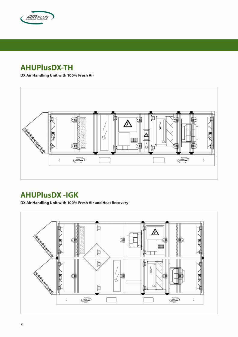
AHUPlusDX -IGKDX Air Handling Unit with 100% Fresh Air and Heat Recovery
AHUPlusDX-THDX Air Handling Unit with 100% Fresh Air

43
AHUPlusDX-KHDX Air Handling Unit with Mixing Section
44
on-off Dam
per with M
otor
F7 Kom
pakt Filtre
F4 Panel Filtre
Mahal Ü
fleme Plug Fan
Dam
la Tutucu
DX
Batarya D
X Coil
EXP V
alve
Elektrikli Ön Isıtıcı
Plakalı Isı Eşanjörü
Exhaust Plug Fan
MCC - DDC
Bakır Boru Tesisatı
VRF External Unit
F7 Com
pact Filter
F4 Panel Filter
on-off Motorlu D
amper
on-off Dam
per with M
otoron-off M
otorlu Dam
per
F4 Panel FiltreF4 Panel Filter
Electrical Heater
on-off Dam
per with M
otoron-off M
otorlu Dam
per
on-off Dam
per with M
otoron-off M
otorlu Dam
per
Plate type Heat Recovery
Drift Elim
inator
Inside Blow
ing Plug Fan
Egzoz Plug Fan
VRF Dış ÜniteVRF External UnitVRF Dış Ünite
Copper Pipe Line
- The most important advantage is that there is much less energy loss at fluid pipes,
- With high COP values, it is an advantageous system in terms of operating and investment costs, it provides new, easy and quick solution for small and medium sized facilities with only one investment,
- Heating and cooling is performed by single external VRF unit, reduces operating costs for heating and cooling,
- Thanks to compressors with variable capacity (inverter technology) and fans used, it provides optimal control, so that it is controlled locally and it consumes only required amount of power,
- Ability to give fast response to partial loads,- Saving wide area required for water cooling group and boiler,
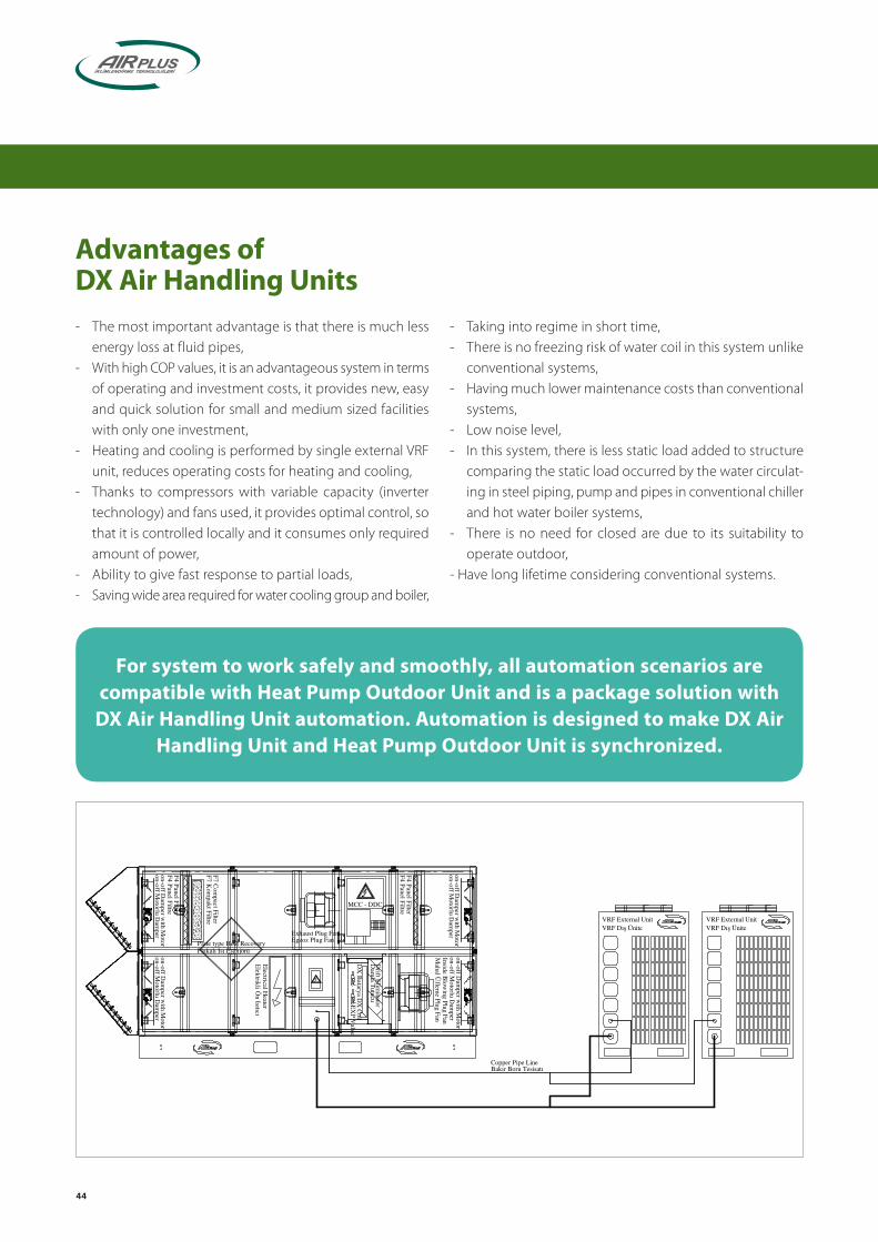
Advantages ofDX Air Handling Units
For system to work safely and smoothly, all automation scenarios are compatible with Heat Pump Outdoor Unit and is a package solution with
DX Air Handling Unit automation. Automation is designed to make DX Air Handling Unit and Heat Pump Outdoor Unit is synchronized.
- Taking into regime in short time, - There is no freezing risk of water coil in this system unlike
conventional systems, - Having much lower maintenance costs than conventional
systems,- Low noise level,- In this system, there is less static load added to structure
comparing the static load occurred by the water circulat-ing in steel piping, pump and pipes in conventional chiller and hot water boiler systems,
- There is no need for closed are due to its suitability to operate outdoor,
- Have long lifetime considering conventional systems.
45
1) Our DX Air Handling Units are manufactured in 1.800 and 25.000 m³/h range and 14 and 224 kW cooling capacity range.
2) High efficient rotary type or plate type heat exchanger provides energy conservation.
3) DX Air Handling Units have 42 mm Rockwool (50 kg/m³) insulated panel construction.
4) All following warning and safety signs and capacity information labels are placed on Air Handling Unit. (Warning signs are indelible and not affected by heat, cold and UV rays from sun.)
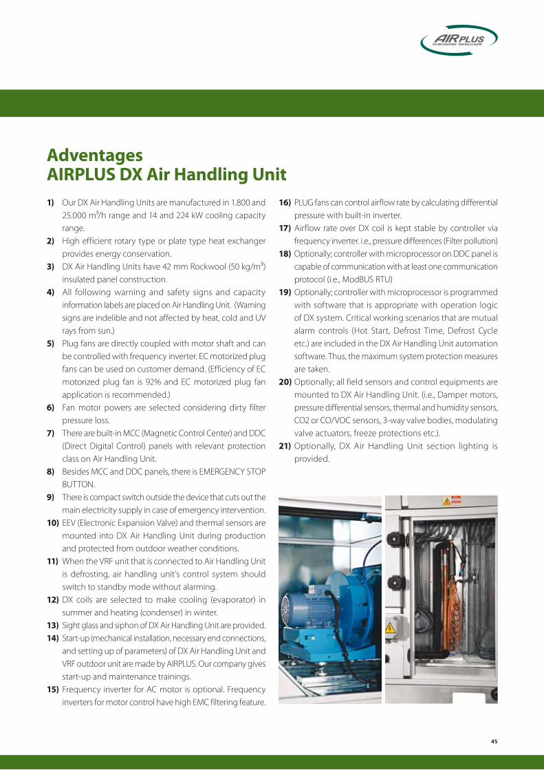
5) Plug fans are directly coupled with motor shaft and can be controlled with frequency inverter. EC motorized plug fans can be used on customer demand. (Efficiency of EC motorized plug fan is 92% and EC motorized plug fan application is recommended.)
6) Fan motor powers are selected considering dirty filter pressure loss.
7) There are built-in MCC (Magnetic Control Center) and DDC (Direct Digital Control) panels with relevant protection class on Air Handling Unit.
8) Besides MCC and DDC panels, there is EMERGENCY STOP BUTTON.
9) There is compact switch outside the device that cuts out the main electricity supply in case of emergency intervention.
10) EEV (Electronic Expansion Valve) and thermal sensors are mounted into DX Air Handling Unit during production and protected from outdoor weather conditions.
11) When the VRF unit that is connected to Air Handling Unit is defrosting, air handling unit’s control system should switch to standby mode without alarming.
12) DX coils are selected to make cooling (evaporator) in summer and heating (condenser) in winter.
13) Sight glass and siphon of DX Air Handling Unit are provided.14) Start-up (mechanical installation, necessary end connections,
and setting up of parameters) of DX Air Handling Unit and VRF outdoor unit are made by AIRPLUS. Our company gives start-up and maintenance trainings.
15) Frequency inverter for AC motor is optional. Frequency inverters for motor control have high EMC filtering feature.
AdventagesAIRPLUS DX Air Handling Unit
16) PLUG fans can control airflow rate by calculating differential pressure with built-in inverter.
17) Airflow rate over DX coil is kept stable by controller via frequency inverter. i.e., pressure differences (Filter pollution)
18) Optionally; controller with microprocessor on DDC panel is capable of communication with at least one communication protocol (i.e., ModBUS RTU)
19) Optionally; controller with microprocessor is programmed with software that is appropriate with operation logic of DX system. Critical working scenarios that are mutual alarm controls (Hot Start, Defrost Time, Defrost Cycle etc.) are included in the DX Air Handling Unit automation software. Thus, the maximum system protection measures are taken.
20) Optionally; all field sensors and control equipments are mounted to DX Air Handling Unit. (i.e., Damper motors, pressure differential sensors, thermal and humidity sensors, CO2 or CO/VOC sensors, 3-way valve bodies, modulating valve actuators, freeze protections etc.).
21) Optionally, DX Air Handling Unit section lighting is provided.

DX AHU Flow Chart
AI
AODO
T
T
SM
SM
T
G4
PD
G4
PD
SM
DX
F7
PDDPT
MV
DPT
T
MV
Pre
DOAO
DIDIAI
Supply F
an On-O
ff
Supply F
an Fault S
tatus
Supply F
an VSD C
ontrolR
eturn Fan O
n-Off
Return F
an Fault S
tatus
Return F
an VSDC
ontrol
AHU
Kit On-O
ff
DX U
nit Cooling M
od On-O
ff
DX U
nit Heating M
od On-O
ff
DX U
nit Fault S
tatus
DX U
nit Run S
tatus
DX U
nit External S
et Point
PhaseFailure Alarm
EmergencyAlarm
Fire Alarm
AHU General On-OffRemote
Fault
Alarm Acknowledge
Emergency Stop Reset Circurit
VRF Outdoor Unit
AHU KIT
46
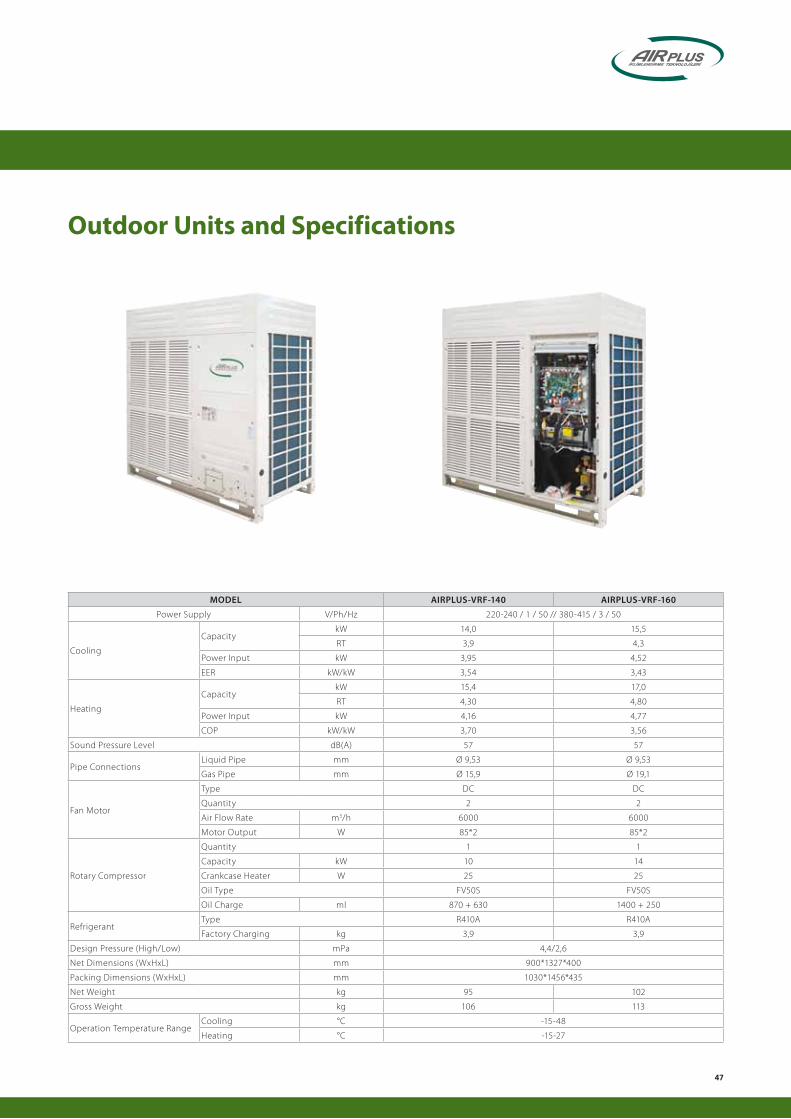
Outdoor Units and Specifications
MODEL AIRPLUS-VRF-140 AIRPLUS-VRF-160
Power Supply V/Ph/Hz 220-240 / 1 / 50 // 380-415 / 3 / 50
Cooling
CapacitykW 14,0 15,5
RT 3,9 4,3
Power Input kW 3,95 4,52
EER kW/kW 3,54 3,43
Heating
CapacitykW 15,4 17,0
RT 4,30 4,80
Power Input kW 4,16 4,77
COP kW/kW 3,70 3,56
Sound Pressure Level dB(A) 57 57
Pipe ConnectionsLiquid Pipe mm Ø 9,53 Ø 9,53
Gas Pipe mm Ø 15,9 Ø 19,1
Fan Motor
Type DC DC
Quantity 2 2
Air Flow Rate m3/h 6000 6000
Motor Output W 85*2 85*2
Rotary Compressor
Quantity 1 1
Capacity kW 10 14
Crankcase Heater W 25 25
Oil Type FV50S FV50S
Oil Charge ml 870 + 630 1400 + 250
Refrigerant Type R410A R410A
Factory Charging kg 3,9 3,9
Design Pressure (High/Low) mPa 4,4/2,6
Net Dimensions (WxHxL) mm 900*1327*400
Packing Dimensions (WxHxL) mm 1030*1456*435
Net Weight kg 95 102
Gross Weight kg 106 113
Operation Temperature RangeCooling °C -15-48
Heating °C -15-27
47

Outdoor Units and SpecificationsMODEL AIRPLUS-VRF-252 AIRPLUS-VRF-280 AIRPLUS-VRF-335
Power Supply V/Ph/Hz 380-415 / 3 / 50
CoolingCapacity kW 25,2 28,0 33,5
RT 7,2 8,0 9,5Power Input kW 5,88 7,20 9,05EER kW/kW 4,29 3,89 3,70
HeatingCapacity kW 27,0 31,5 37,5
RT 7,70 9,00 10,70Power Input kW 6,15 7,61 8,99COP kW/kW 4,39 4,14 4,17
Sound Pressure Level dB(A) 57 57 59
Pipe ConnectionsLiquid Pipe mm Ø 9,53 Ø 9,53 Ø 12,7Gas Pipe mm Ø 22,2 Ø 22,2 Ø 25,4Oil Balance Pipe mm Ø 6 Ø 6 Ø 6
Fan Motor
Type DC DC DC + ACQuantity 1 1 1 + 1Air Flow Rate m3/h 11500 11500 15100Motor Output W 750 750 560 + 380
ESP Pa 0-20 (default) 0-20 (default) 0-20 (default)Pa 20-40 (customized) 20-40 (customized) 20-60 (customized)
DC Inverter Compressor
Quantity 1 1 1Capacity kW 31,59 31,59 11,80Crankcase Heater W 27,6*2 27,6*2 27,6*2Oil Type FVC68D FVC68D FVC68DOil Charge ml 500 500 500
Scroll Compressor
Quantity - - 1Capacity kW - - 17,1Crankcase Heater W - - 27,6Oil Type - - FVC68DOil Charge ml - - 500
Refrigerant Type R410A R410A R410AFactory Charging kg 9 9 11
Design Pressure (High/Low) mPa 4,4/2,6 4,4/2,6 4,4/2,6Net Dimensions (WxHxL) mm 960*1615*765 960*1615*765 1250*1615*765Packing Dimensions (WxHxL) mm 1025*1790*830 1025*1790*830 1305*1790*820Net Weight kg 198 198 268Gross Weight kg 213 213 288Operation Temperature Range
Cooling °C -5-48Heating °C -20-27MODEL AIRPLUS-VRF-400 AIRPLUS-VRF-450 AIRPLUS-VRF-500
Power Supply V/Ph/Hz 380-415 / 3 / 50
CoolingCapacity kW 40,0 45,0 50,0
RT 11,4 12,8 14,2Power Input kW 12,31 14,02 15,20EER kW/kW 3,25 3,21 3,29
HeatingCapacity kW 45,0 50,0 56,0
RT 12,80 14,20 15,90Power Input kW 11,19 12,79 14,25COP kW/kW 4,02 3,91 3,93
Sound Pressure Level dB(A) 60 60 61
Pipe ConnectionsLiquid Pipe mm Ø 15,9 Ø 15,9 Ø 19,1Gas Pipe mm Ø 31,8 Ø 31,8 Ø 31,8Oil Balance Pipe mm Ø 6 Ø 6 Ø 6
Fan Motor
Type DC + AC DC + AC DC + ACQuantity 1 + 1 1 + 1 1 + 1Air Flow Rate m3/h 15100 15100 15200Motor Output W 560 + 380 560 + 380 560 + 380
ESP Pa 0-20 (default) 0-20 (default) 0-20 (default)Pa 20-40 (customized) 20-40 (customized) 20-60 (customized)
DC Inverter Compressor
Quantity 1 1 1Capacity kW 31,59 31,59 11,80Crankcase Heater W 27,6*2 27,6*2 27,6*2Oil Type FVC68D FVC68D FVC68DOil Charge ml 500 500 500
Scroll Compressor
Quantity 1 1 1Capacity kW 13,39 13,39 20,9Crankcase Heater W 27,6 27,6 27,6Oil Type FVC68D FVC68D FVC68DOil Charge ml 500 500 500
Refrigerant Type R410A R410A R410AFactory Charging kg 13 13 16
Design Pressure (High/Low) mPa 4,4/2,6 4,4/2,6 4,4/2,6Net Dimensions (WxHxL) mm 1250*1615*765 1250*1615*765 1250*1615*765Packing Dimensions (WxHxL) mm 1305*1790*820 1305*1790*820 1305*1790*820Net Weight kg 280 280 300Gross Weight kg 300 300 320Operation Temperature Range
Cooling °C -5-48Heating °C -20-27
48

MODEL AIRPLUS-VRF-I-200 AIRPLUS-VRF-I-224 AIRPLUS-VRF-I-260Power Supply V/Ph/Hz 380-415 / 3 / 50
CoolingCapacity kW 20,0 22,4 26,0
RT 5,7 6,4 7,4Power Input kW 6,10 6,80 7,60EER kW/kW 3,28 3,29 3,42
HeatingCapacity kW 22,0 24,5 28,5
RT 6,30 7,00 8,10Power Input kW 6,10 5,90 6,80COP kW/kW 3,61 4,15 4,19
Sound Pressure Level dB(A) 59 59 60
Pipe Connections Liquid Pipe mm Ø 9,53 Ø 9,53 Ø 9,53Gas Pipe mm Ø 19,1 Ø 19,1 Ø 22,2
Fan Motor
Type DC DC DCQuantity 2 2 2Air Flow Rate m3/h 11000 10500 10500Motor Output W 210 + 160 200 + 150 200 + 150
Scroll Compressor
Quantity 1 1 1Capacity kW 13,98 16,86 16,86Crankcase Heater W 25 25 25Oil Type FV50S FV50S FV50SOil Charge ml 1400 1700 1700
Refrigerant Type R410A R410A R410A
Factory Feed kg 4,8 6,2 6,2Design Pressure (High/Low) mPa 4,4/2,6Net Dimensions (WxHxL) mm 1120*1558*400Packing Dimensions (WxHxL) mm 1270*1720*565Net Weight kg 137 146,5 147Gross Weight kg 153 162,5 163Operation Temperature Range
Cooling °C -15-48Heating °C -15-27MODEL AIRPLUS-VRF-I-560 AIRPLUS-VRF-I-615 AIRPLUS-VRF-I-670
Power Supply V/Ph/Hz 380-415 / 3 / 50
CoolingCapacity kW 56,0 61,5 67,0
RT 15,9 17,5 19,0Power Input kW 17,00 18,80 20,80EER kW/kW 3,30 3,27 3,22
HeatingCapacity kW 63,0 69,0 75,0
RT 17,90 19,60 21,30Power Input kW 16,00 17,90 19,80COP kW/kW 3,94 3,86 3,79
Sound Pressure Level dB(A) 62 63 63
Pipe Connections Liquid Pipe mm Ø 19,1 Ø 19,1 Ø 19,1Gas Pipe mm Ø 31,8 Ø 31,8 Ø 31,8
Fan Motor
Type DC + AC DC + AC DC + ACQuantity 2 2 4Air Flow Rate m3/h 20000 23000 23000Motor Output W 340 + 450 625 + 450 625 + 450
ESP Pa 0-20 (default)Pa 20-40 (customized)
DC Inverter Compressor
Quantity 1 1 1Capacity kW 31,59 31,59 31,59Crankcase Heater W 33*2 33*2 33*2Oil Type FVC68D FVC68D FVC68DOil Charge ml 500 500 500
Rotary Compressor
Quantity 2 2 2Capacity kW 15,39*2 17,1*2 20,9*2Crankcase Heater W 27,6 27,6 27,6Oil Type FVC68D FVC68D FVC68DOil Charge ml 500*2 500*2 1100*2
Refrigerant Type R410A R410A R410AFactory Feed kg 17 18,5 18,5
Design Pressure (High/Low) mPa 4,4/2,6Net Dimensions (WxHxL) mm 1390*1615*765 1585*1615*765 1585*1615*765Packing Dimensions (WxHxL) mm 1455*1790*830 1650*1810*840 1650*1810*840Net Weight kg 360 385 390Gross Weight kg 375 400 405Operation Temperature Range
Cooling °C -5-48Heating °C -20-27
Outdoor Units and Specifications
49