ahk column shoes - anstar.fi
TRANSCRIPT

AHK Column Shoes User Manual
2
User Manual AHK Column Shoes Revision 1/2020

AHK Column Shoes User Manual
3
User Manual AHK Column Shoes Revision 1/2020
TABLE OF CONTENTS 1 AHK COLUMN SHOES .................................................................................................................................................................. 4 2 SHOE APPLICATIONS ................................................................................................................................................................... 4
2.1 Element frames of office buildings, rectangular columns .................................................................................................... 4 2.2 Element frames of commercial and office buildings, round columns ................................................................................... 5 2.3 Shoe connections for asymmetrical rectangular columns ................................................................................................... 5 2.4 AHK column shoes ............................................................................................................................................................. 6 2.5 AHK-K middle shoes .......................................................................................................................................................... 7
3 MANUFACTURING INFORMATION ............................................................................................................................................... 8 4 Design CRITERIA ........................................................................................................................................................................... 9
4.1 Design and manufacturing codes ....................................................................................................................................... 9 4.2 Shoe resistance values ...................................................................................................................................................... 9
4.2.1 Axial force resistance of shoes............................................................................................................................ 9 4.2.2 Shear resistance of the shoe connection .......................................................................................................... 10 4.2.3 Concrete strengths of the shoe connection ....................................................................................................... 10 4.2.4 Minimum column size for the shoe connection .................................................................................................. 11
4.3 Shoe connection design instructions for the main civil engineer ....................................................................................... 11 5 DETAIL DESIGN .......................................................................................................................................................................... 14
5.1 Design states and parties ................................................................................................................................................. 14 5.2 Design software ACOLUMN ............................................................................................................................................. 14 5.3 Design of shoe connection ............................................................................................................................................... 16
5.3.1 Project folder and calculation code ................................................................................................................... 16 5.3.2 Selecting the connection type and materials ..................................................................................................... 17 5.3.3 Initial data ......................................................................................................................................................... 17 5.3.4 Calculation forces ............................................................................................................................................. 20 5.3.5 Placing the shoes and bolts in the connection ................................................................................................... 21 5.3.6 Placing the rebar in the connection ................................................................................................................... 23
5.4 Erection state. Bolts ......................................................................................................................................................... 25 5.4.1 Presentation of the results ................................................................................................................................ 25 5.4.2 Erection state resistance of bolts ...................................................................................................................... 26
5.5 Ultimate limit state. Shoes ................................................................................................................................................ 27 5.5.1 Shoes’ resistance. Axial force ........................................................................................................................... 27 5.5.2 Supplementary reinforcement for the shoe connection ...................................................................................... 29
5.6 Ultimate limit state. Rebar bolts ........................................................................................................................................ 31 5.6.1 Resistance graph for the column and grouting cross-section ............................................................................ 31 5.6.2 Stress state of the column’s grouting cross-section ........................................................................................... 32
5.7 Shoe connection’s service life design ............................................................................................................................... 33 6 SHOE CONNECTION MANUFACTURE AT THE FACTORY ....................................................................................................... 35
6.1 Shoe delivery, storage and identification .......................................................................................................................... 35 6.2 Installing the shoes into the column formwork .................................................................................................................. 35 6.3 Casting protection for the shoes and casting the column .................................................................................................. 36 6.4 Corrective measures allowed for shoes at the element plant ............................................................................................ 36 6.5 Manufacture quality control............................................................................................................................................... 37 6.6 Final documentation of manufacture quality control .......................................................................................................... 37
7 INSTALLING THE SHOE CONNECTION ON THE SITE .............................................................................................................. 38 7.1 Standards and plans to be followed during installation ...................................................................................................... 38 7.2 Bolt elevation and nut torque ............................................................................................................................................ 38 7.3 Column installation, grouting and fire protection ............................................................................................................... 38 7.4 Installation tolerances for the shoe connection ................................................................................................................. 40 7.5 Corrective measures allowed for the shoe connection on the site ..................................................................................... 41
8 SAFETY MEASURES ................................................................................................................................................................... 42 8.1 Information for preparing work safety instructions for the site ........................................................................................... 42 8.2 Commissioning a shoe connection during construction ..................................................................................................... 42
9 INSTALLATION QUALITY CONTROL .......................................................................................................................................... 43 9.1 Instructions for monitoring column installations ................................................................................................................. 43 9.2 Final documentation of installation quality control ............................................................................................................. 43
Revisio D. Janyary 31.2020 User manual has been updated according to EN 1992-4:2018. Resistance values have small canges Text has been updated Software version ACOLUMN 5.0 shall be used.
Revision C – 31 Mai 2018 Editorial changes. Translated to English Revision B – 31 December 2017 Instructions for using AHK shoes have been completely rewritten. The structure of AHK shoes has remained unchanged. The bond lengths have also been checked according to the DIN-EN standard. AHK-K shoes are new products to be used as middle shoes in rectangular columns and shoes in round columns. The shoe resistance values have been changed in accordance with the revised anchor bolt user manual. The old COLJOINT design software for shoe connections has been completely redesigned and the old software is no longer used. Anstar’s new design software applications are ACOLUMN for concrete column connections and ASTEEL for steel column connections.
This user manual only applies to designing and using Anstar Oy products included in this document. The manual or parts of it cannot be adapted or applied to designing other manufacturers’ products or manufacturing or using concrete elements in column shoe connections.
AHK Column Shoes User Manual
4
User Manual AHK Column Shoes Revision 1/2020
1 AHK COLUMN SHOES
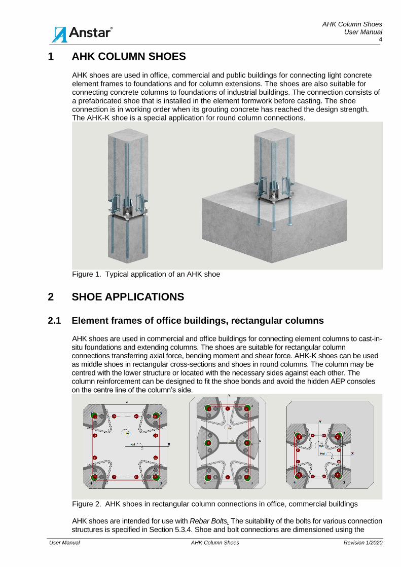
AHK shoes are used in office, commercial and public buildings for connecting light concrete element frames to foundations and for column extensions. The shoes are also suitable for connecting concrete columns to foundations of industrial buildings. The connection consists of a prefabricated shoe that is installed in the element formwork before casting. The shoe connection is in working order when its grouting concrete has reached the design strength. The AHK-K shoe is a special application for round column connections.
Figure 1. Typical application of an AHK shoe
2 SHOE APPLICATIONS
2.1 Element frames of office buildings, rectangular columns AHK shoes are used in commercial and office buildings for connecting element columns to cast-in-situ foundations and extending columns. The shoes are suitable for rectangular column connections transferring axial force, bending moment and shear force. AHK-K shoes can be used as middle shoes in rectangular cross-sections and shoes in round columns. The column may be centred with the lower structure or located with the necessary sides against each other. The column reinforcement can be designed to fit the shoe bonds and avoid the hidden AEP consoles on the centre line of the column’s side.
Figure 2. AHK shoes in rectangular column connections in office, commercial buildings AHK shoes are intended for use with Rebar Bolts. The suitability of the bolts for various connection structures is specified in Section 5.3.4. Shoe and bolt connections are dimensioned using the
AHK Column Shoes User Manual
5
User Manual AHK Column Shoes Revision 1/2020
ACOLUMN software, which can also be used to dimension the column’s main reinforcement in the shoe area.
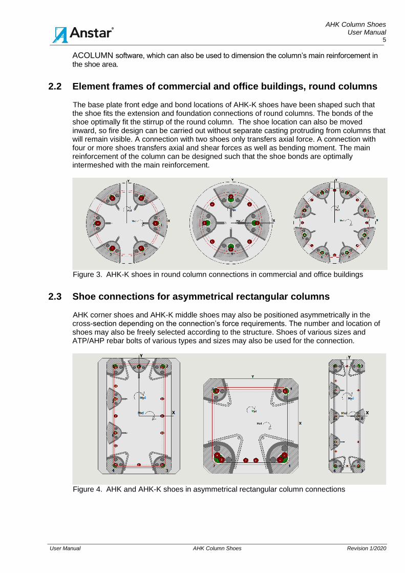
2.2 Element frames of commercial and office buildings, round columns The base plate front edge and bond locations of AHK-K shoes have been shaped such that the shoe fits the extension and foundation connections of round columns. The bonds of the shoe optimally fit the stirrup of the round column. The shoe location can also be moved inward, so fire design can be carried out without separate casting protruding from columns that will remain visible. A connection with two shoes only transfers axial force. A connection with four or more shoes transfers axial and shear forces as well as bending moment. The main reinforcement of the column can be designed such that the shoe bonds are optimally intermeshed with the main reinforcement.
Figure 3. AHK-K shoes in round column connections in commercial and office buildings
2.3 Shoe connections for asymmetrical rectangular columns AHK corner shoes and AHK-K middle shoes may also be positioned asymmetrically in the cross-section depending on the connection’s force requirements. The number and location of shoes may also be freely selected according to the structure. Shoes of various sizes and ATP/AHP rebar bolts of various types and sizes may also be used for the connection.
Figure 4. AHK and AHK-K shoes in asymmetrical rectangular column connections
AHK Column Shoes User Manual
6
User Manual AHK Column Shoes Revision 1/2020
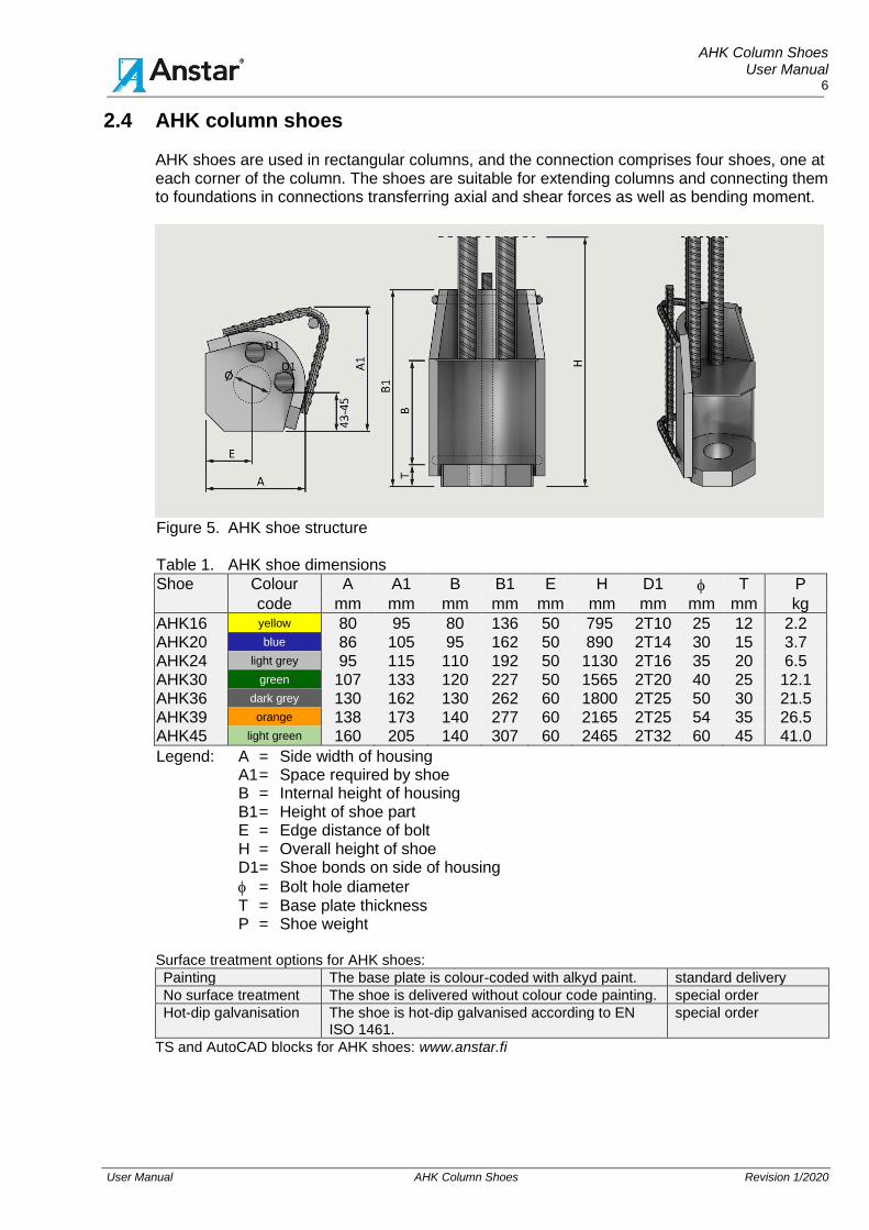
2.4 AHK column shoes AHK shoes are used in rectangular columns, and the connection comprises four shoes, one at each corner of the column. The shoes are suitable for extending columns and connecting them to foundations in connections transferring axial and shear forces as well as bending moment.
Figure 5. AHK shoe structure
Table 1. AHK shoe dimensions
Shoe Colour A A1 B B1 E H D1 T P
code mm mm mm mm mm mm mm mm mm kg
AHK16 yellow 80 95 80 136 50 795 2T10 25 12 2.2 AHK20 blue 86 105 95 162 50 890 2T14 30 15 3.7 AHK24 light grey 95 115 110 192 50 1130 2T16 35 20 6.5 AHK30 green 107 133 120 227 50 1565 2T20 40 25 12.1 AHK36 dark grey 130 162 130 262 60 1800 2T25 50 30 21.5 AHK39 orange 138 173 140 277 60 2165 2T25 54 35 26.5 AHK45 light green 160 205 140 307 60 2465 2T32 60 45 41.0 Legend: A = Side width of housing
A1 = Space required by shoe B = Internal height of housing B1 = Height of shoe part E = Edge distance of bolt H = Overall height of shoe D1 = Shoe bonds on side of housing
= Bolt hole diameter T = Base plate thickness P = Shoe weight
Surface treatment options for AHK shoes:
Painting The base plate is colour-coded with alkyd paint. standard delivery
No surface treatment The shoe is delivered without colour code painting. special order
Hot-dip galvanisation The shoe is hot-dip galvanised according to EN ISO 1461.
special order
TS and AutoCAD blocks for AHK shoes: www.anstar.fi
AHK Column Shoes User Manual
7
User Manual AHK Column Shoes Revision 1/2020
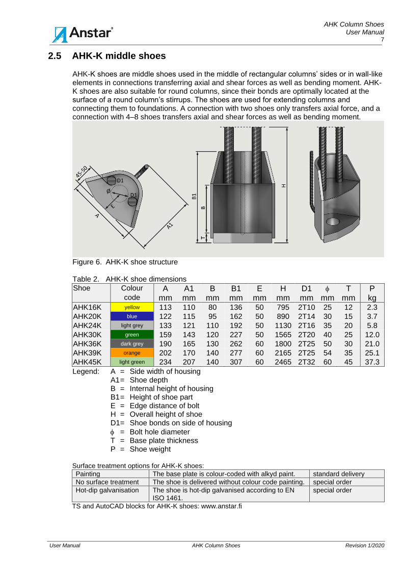
2.5 AHK-K middle shoes
AHK-K shoes are middle shoes used in the middle of rectangular columns’ sides or in wall-like elements in connections transferring axial and shear forces as well as bending moment. AHK-K shoes are also suitable for round columns, since their bonds are optimally located at the surface of a round column’s stirrups. The shoes are used for extending columns and connecting them to foundations. A connection with two shoes only transfers axial force, and a connection with 4–8 shoes transfers axial and shear forces as well as bending moment.
Figure 6. AHK-K shoe structure Table 2. AHK-K shoe dimensions
Shoe Colour A A1 B B1 E H D1 T P code mm mm mm mm mm mm mm mm mm kg
AHK16K yellow 113 110 80 136 50 795 2T10 25 12 2.3
AHK20K blue 122 115 95 162 50 890 2T14 30 15 3.7
AHK24K light grey 133 121 110 192 50 1130 2T16 35 20 5.8
AHK30K green 159 143 120 227 50 1565 2T20 40 25 12.0
AHK36K dark grey 190 165 130 262 60 1800 2T25 50 30 21.0
AHK39K orange 202 170 140 277 60 2165 2T25 54 35 25.1
AHK45K light green 234 207 140 307 60 2465 2T32 60 45 37.3 Legend: A = Side width of housing
A1 = Shoe depth B = Internal height of housing B1 = Height of shoe part E = Edge distance of bolt H = Overall height of shoe D1 = Shoe bonds on side of housing
= Bolt hole diameter T = Base plate thickness P = Shoe weight
Surface treatment options for AHK-K shoes:
Painting The base plate is colour-coded with alkyd paint. standard delivery
No surface treatment The shoe is delivered without colour code painting. special order
Hot-dip galvanisation The shoe is hot-dip galvanised according to EN ISO 1461.
special order
TS and AutoCAD blocks for AHK-K shoes: www.anstar.fi
AHK Column Shoes User Manual
8
User Manual AHK Column Shoes Revision 1/2020
3 MANUFACTURING INFORMATION
ANSTAR Oy has entered into a quality control agreement with KIWA Inspecta Oy regarding the manufacture of AHK shoes. The manufacturing information for the shoes is as follows:
1. Manu-factoring markings
Shoe manufacturing markings: - Manufacture according to EN 1090-2:2018 for steel parts. [2] - ANSTAR’s code - Shoe code with a colour code - Packaging: shrink-wrapped on a pallet
2. Materials Manufacturing materials: - Base plate EN 10025-2 S355J2+N - Housing EN 10025-2 S355J2+N - Rebar EN 10080 , SFS 1300 B500B - Impact test temperature for the materials: –20 oC
3. Manu-factoring method
Shoe manufacture: - Shoes are manufactured according to the EN 1090-2:2018 standard in
execution class EXC2. By special order, they can be manufactured in execution class EXC3.
- The welding class is C as standard and B by special order, EN ISO 5817. [11]
- Rebar welding EN 17660-1 [16] - Manufacturing tolerances EN 1090-2:2018 [2]
4. Surface treatment methods
Surface treatment methods for shoes: - The bottom surface of the base plate is colour-coded by painting. - Delivery without colour code painting by special order. - Shoes are hot-dip galvanised by special order according to EN-ISO 1461.
[13]
5. Product approval and quality control
Product quality control: Certificate 0416-CPR-7247-03. Product declaration: CE marking according to EN 1090-1. European Countries: Sweden, Denmark, Norway, Austria, Estonia, Latvia, Lithuania. Additional information: www.anstar.fi/en
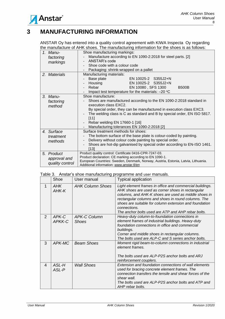
Table 3. Anstar’s shoe manufacturing programme and user manuals.
Shoe User manual Typical application
1 AHK AHK-K
AHK Column Shoes Light element frames in office and commercial buildings. AHK shoes are used as corner shoes in rectangular columns, and AHK-K shoes are used as middle shoes in rectangular columns and shoes in round columns. The shoes are suitable for column extension and foundation connections. The anchor bolts used are ATP and AHP rebar bolts.
2 APK-C APKK-C
APK-C Column Shoes
Heavy-duty column-to-foundation connections in element frames of industrial buildings. Heavy-duty foundation connections in office and commercial buildings. Corner and middle shoes in rectangular columns. The bolts used are ALP-C and S series anchor bolts.
3 APK-MC Beam Shoes Moment rigid beam-to-column connections in industrial element frames. The bolts used are ALP-P2S anchor bolts and ARJ reinforcement couplers.
4 ASL-H ASL-P
Wall Shoes
Extension and foundation connections of wall elements used for bracing concrete element frames. The connection transfers the tensile and shear forces of the shear wall. The bolts used are ALP-P2S anchor bolts and ATP and AHP rebar bolts.
AHK Column Shoes User Manual
9
User Manual AHK Column Shoes Revision 1/2020
4 DESIGN CRITERIA
4.1 Design and manufacturing codes
1. Finnish standards
SFS-EN 1991-1+NA Actions on structures. Part 1-1: General actions. [5]
SFS-EN 1992-1-1+NA Design of concrete structures. Part 1-1: General rules and rules for buildings. [6]
SFS-EN 1993-1+NA Design of steel structures. Part 1-1: General rules. [8]
SFS-EN 13670 Execution of concrete structures, execution class 2 or 3, [17]
SFS-EN 13225 Connection manufacture at element plant: [18]
2. Other countries in the European Code area
Basic Eurocode EN-1992-1-1:2004/AC:2010
Sweden SS-EN 1992-1-1:2005/AC:2010+A1/2014 + EKS 11
Germany DIN-EN 1992-1-1 +NA/2013-04
3. Shoe manufacture
EN 1090-1 Execution of steel structures. Part 1: Requirements for conformity assessment of structural components. [1]
EN 1090-2:2018 Execution of steel structures. Part 2: Technical requirements for steel structures. Execution classes EXC2 and EXC3. [2]
EN 13670 Execution of concrete structures. Execution class 2 or 3. [17]
EN-ISO 5817 Welding. Fusion-welded joints in steel, nickel, titanium and their alloys.
EN 17760-1 Welding. Welding of reinforcing steel. Part 1: Load-bearing welded joints. [16]
4.2 Shoe resistance values
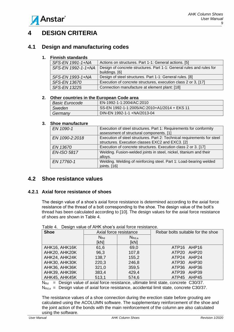
4.2.1 Axial force resistance of shoes The design value of a shoe’s axial force resistance is determined according to the axial force
resistance of the thread of a bolt corresponding to the shoe. The design value of the bolt’s thread has been calculated according to [10]. The design values for the axial force resistance of shoes are shown in Table 4.
Table 4. Design value of AHK shoe’s axial force resistance.
Shoe
Axial force resistance Rebar bolts suitable for the shoe
NRd NRd,a [kN] [kN]
AHK16, AHK16K 61,6 69,0 ATP16 AHP16
AHK20, AHK20K 96,3 107,8 ATP20 AHP20
AHK24, AHK24K 138,7 155,2 ATP24 AHP24
AHK30, AHK30K 220,3 246,8 ATP30 AHP30
AHK36, AHK36K 321,0 359,5 ATP36 AHP36
AHK39, AHK39K 383,4 429,4 ATP39 AHP39
AHK45, AHK45K 513,1 574,6 ATP45 AHP45
NRd = Design value of axial force resistance, ultimate limit state, concrete C30/37. NRd,a = Design value of axial force resistance, accidental limit state, concrete C30/37. The resistance values of a shoe connection during the erection state before grouting are calculated using the ACOLUMN software. The supplementary reinforcement of the shoe and the joint action of the bonds with the main reinforcement of the column are also calculated using the software.
AHK Column Shoes User Manual
10
User Manual AHK Column Shoes Revision 1/2020
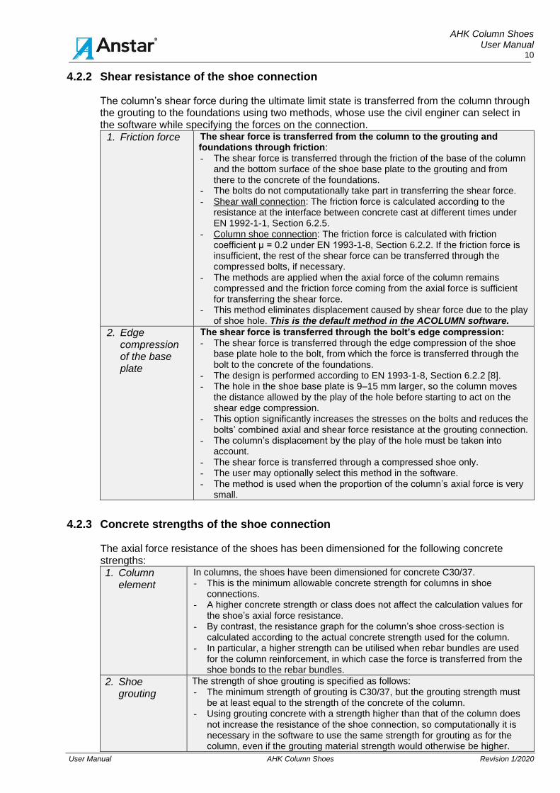
4.2.2 Shear resistance of the shoe connection The column’s shear force during the ultimate limit state is transferred from the column through the grouting to the foundations using two methods, whose use the civil enginer can select in the software while specifying the forces on the connection.
1. Friction force
The shear force is transferred from the column to the grouting and foundations through friction: - The shear force is transferred through the friction of the base of the column
and the bottom surface of the shoe base plate to the grouting and from there to the concrete of the foundations.
- The bolts do not computationally take part in transferring the shear force. - Shear wall connection: The friction force is calculated according to the
resistance at the interface between concrete cast at different times under EN 1992-1-1, Section 6.2.5.
- Column shoe connection: The friction force is calculated with friction coefficient μ = 0.2 under EN 1993-1-8, Section 6.2.2. If the friction force is insufficient, the rest of the shear force can be transferred through the compressed bolts, if necessary.
- The methods are applied when the axial force of the column remains compressed and the friction force coming from the axial force is sufficient for transferring the shear force.
- This method eliminates displacement caused by shear force due to the play of shoe hole. This is the default method in the ACOLUMN software.
2. Edge compression of the base plate
The shear force is transferred through the bolt’s edge compression: - The shear force is transferred through the edge compression of the shoe
base plate hole to the bolt, from which the force is transferred through the bolt to the concrete of the foundations.
- The design is performed according to EN 1993-1-8, Section 6.2.2 [8]. - The hole in the shoe base plate is 9–15 mm larger, so the column moves
the distance allowed by the play of the hole before starting to act on the shear edge compression.
- This option significantly increases the stresses on the bolts and reduces the bolts’ combined axial and shear force resistance at the grouting connection.
- The column’s displacement by the play of the hole must be taken into account.
- The shear force is transferred through a compressed shoe only. - The user may optionally select this method in the software. - The method is used when the proportion of the column’s axial force is very
small.
4.2.3 Concrete strengths of the shoe connection The axial force resistance of the shoes has been dimensioned for the following concrete strengths:
1. Column element
In columns, the shoes have been dimensioned for concrete C30/37. - This is the minimum allowable concrete strength for columns in shoe
connections. - A higher concrete strength or class does not affect the calculation values for
the shoe’s axial force resistance. - By contrast, the resistance graph for the column’s shoe cross-section is
calculated according to the actual concrete strength used for the column. - In particular, a higher strength can be utilised when rebar bundles are used
for the column reinforcement, in which case the force is transferred from the shoe bonds to the rebar bundles.
2. Shoe grouting
The strength of shoe grouting is specified as follows: - The minimum strength of grouting is C30/37, but the grouting strength must
be at least equal to the strength of the concrete of the column. - Using grouting concrete with a strength higher than that of the column does
not increase the resistance of the shoe connection, so computationally it is necessary in the software to use the same strength for grouting as for the column, even if the grouting material strength would otherwise be higher.

AHK Column Shoes User Manual
11
User Manual AHK Column Shoes Revision 1/2020
- The grouting of the nut slot and base plate transfers the compressive force. - The grouting constitutes the fire protection of the connection. - We recommend using non-shrinking, CE-approved grouting concrete whose
strength is at least equal to that of the concrete of the column. - The quality control of grouting concrete follows the regulations for load-
bearing concrete.
3. Cast-in-situ foundations
The minimum design strength of the foundations and foundation column is C25/30. - This is the minimum allowable strength of the foundation column/foundations
in shoe connections. - The resistance of the bolts in the connection is determined according to the
strength of the concrete of the foundations. - The size of the cross-section of the foundations is adapted to the concrete
strengths.
Figure 7. Column connection’s grouting and minimum concrete strengths
4.2.4 Minimum column size for the shoe connection The minimum column sizes for AHK shoes are shown in Table 5. The shoe placement and suitability for the connection in special cases can be checked using the design software. The minimum rectangular column dimension for middle shoes has been specified taking into account AHK shoes of the same size at the corners of the column. Table 5. Minimum columns for AHK and AHK-K shoes
Shoe AHK
Minimum rectangular
column
Shoe AHK-K
Minimum rectangular
column
Minimum round column,
4 shoes
Minimum round column,
6 shoes
AHK16 200x200 AHK16K 220x300 230 260 AHK20 220x220 AHK20K 230x320 240 280 AHK24 240x240 AHK24K 240x380 250 300 AHK30 280x280 AHK30K 280x420 300 350 AHK36 340x340 AHK36K 340x480 350 420 AHK39 350x350 AHK39K 350x520 360 440 AHK45 420x420 AHK45K 420x600 430 500
4.3 Shoe connection design instructions for the main civil engineer
The shoe connection is designed using ACOLUMN design software. Due to the calculation method, no instructions are provided for manual calculation, and the use of shoes in detail design with approximate calculation methods is not recommended. The software is used for designing shoes in the following connection types:
AHK Column Shoes User Manual
12
User Manual AHK Column Shoes Revision 1/2020
1. Column shoe connections
Frame column connections: - Shoe connections in element column extensions - Shoe connections to foundation columns and cast-in-situ footings - Rectangular and round columns - APK-C, APKK-C and AHK, AHK-K shoes
2. Wall shoe connections
Bracing wall - Extension and foundation connections of bracing element walls - ASL-H and ASL-P wall shoes
3. Moment rigid beam-to-column connections
Moment rigid beam-to-column connection - Moment rigid beam-to-column connections of concrete element frames - APK-MC beam shoes and ARJ series coupler bolts.
4. Steel column connection to foundations
Steel column foundation connection - Anchor bolt connections of steel columns to cast-in-situ foundations - Base plate and shear dowel connections
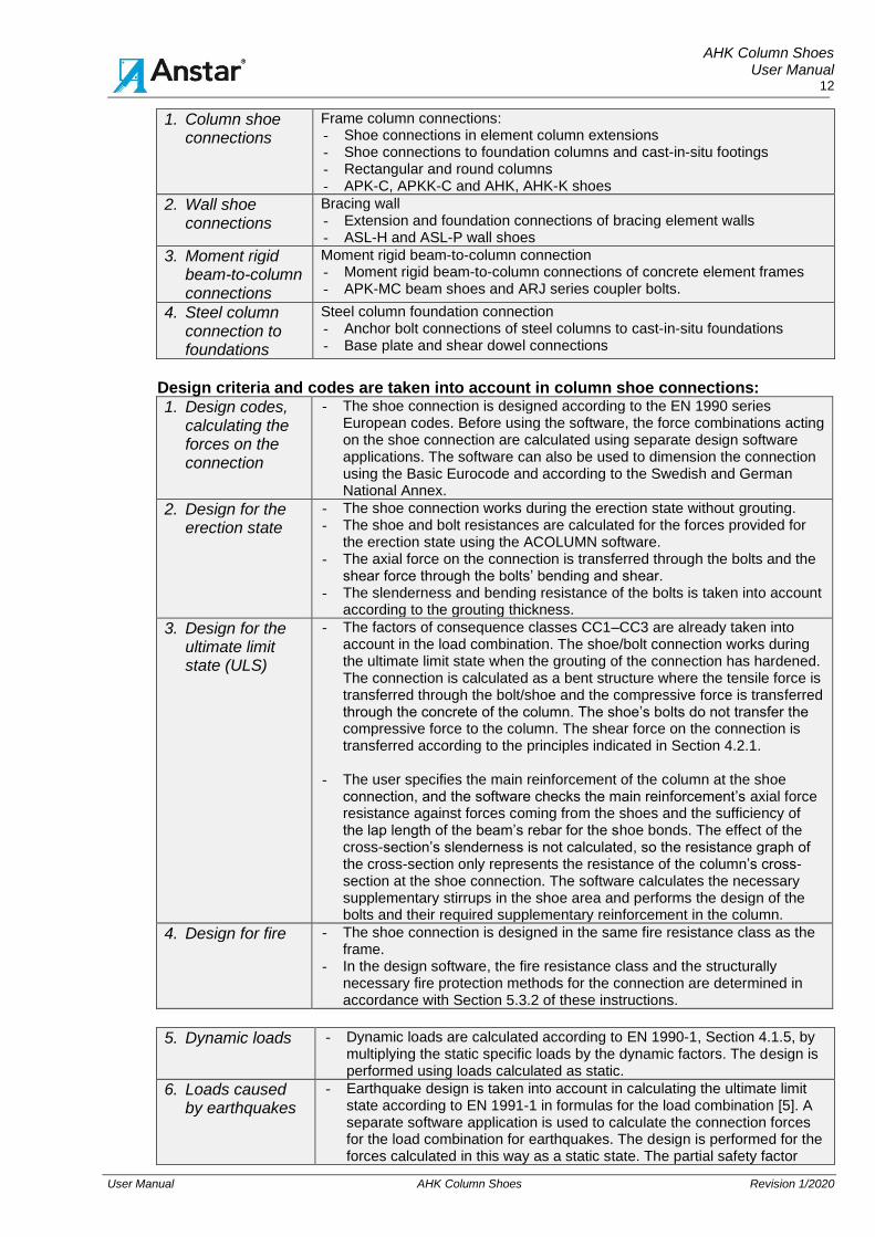
Design criteria and codes are taken into account in column shoe connections:
1. Design codes, calculating the forces on the connection
- The shoe connection is designed according to the EN 1990 series European codes. Before using the software, the force combinations acting on the shoe connection are calculated using separate design software applications. The software can also be used to dimension the connection using the Basic Eurocode and according to the Swedish and German National Annex.
2. Design for the erection state
- The shoe connection works during the erection state without grouting. - The shoe and bolt resistances are calculated for the forces provided for
the erection state using the ACOLUMN software. - The axial force on the connection is transferred through the bolts and the
shear force through the bolts’ bending and shear. - The slenderness and bending resistance of the bolts is taken into account
according to the grouting thickness.
3. Design for the ultimate limit state (ULS)
- The factors of consequence classes CC1–CC3 are already taken into account in the load combination. The shoe/bolt connection works during the ultimate limit state when the grouting of the connection has hardened. The connection is calculated as a bent structure where the tensile force is transferred through the bolt/shoe and the compressive force is transferred through the concrete of the column. The shoe’s bolts do not transfer the compressive force to the column. The shear force on the connection is transferred according to the principles indicated in Section 4.2.1.
- The user specifies the main reinforcement of the column at the shoe connection, and the software checks the main reinforcement’s axial force resistance against forces coming from the shoes and the sufficiency of the lap length of the beam’s rebar for the shoe bonds. The effect of the cross-section’s slenderness is not calculated, so the resistance graph of the cross-section only represents the resistance of the column’s cross-section at the shoe connection. The software calculates the necessary supplementary stirrups in the shoe area and performs the design of the bolts and their required supplementary reinforcement in the column.
4. Design for fire
- The shoe connection is designed in the same fire resistance class as the frame.
- In the design software, the fire resistance class and the structurally necessary fire protection methods for the connection are determined in accordance with Section 5.3.2 of these instructions.
5. Dynamic loads
- Dynamic loads are calculated according to EN 1990-1, Section 4.1.5, by multiplying the static specific loads by the dynamic factors. The design is performed using loads calculated as static.
6. Loads caused by earthquakes
- Earthquake design is taken into account in calculating the ultimate limit state according to EN 1991-1 in formulas for the load combination [5]. A separate software application is used to calculate the connection forces for the load combination for earthquakes. The design is performed for the forces calculated in this way as a static state. The partial safety factor

AHK Column Shoes User Manual
13
User Manual AHK Column Shoes Revision 1/2020
level of the load is selected in accordance with the European codes.
7. Fatigue actions
- The resistance values of AHK shoes have not been specified for fatigue actions. Fatigue design is performed separately on a case-specific basis according to the principles in EN 1990-1, Section 4.1.4. [4]
8. Design for accidental state (ALS)
- A design analysis for accidental limit state is performed for the shoe connection according to EN 1992-1-1, Section 2.4.2.4, by using the partial safety factors of materials in accidental limit state indicated in Table 2.1N of the standard to determine the resistance of the connection in exceptional situations. The calculation is performed using accidental loads. The partial safety factor level of material is in accordance with the factors specified in the EN 1992-1-1, EN 1993-1-1 and EN 1992-4:2018 codes.
- The analysis is performed using the ACOLUMN software. The combination of forces in accidental state is calculated using a separate software application, and the forces on the connection are provided as “Loads in accidental limit state”. The software calculates the accidental resistance values and utilisation rates for various parts of the connection. The partial safety factor level of the shoe materials in accidental state is: concrete γc = 1.2 and sleeve and rebar steel γs = 1.0. The partial safety factor level of the anchoring bolt materials is in accordance with EN 1992-4:2018.
9. Design the anchoring bolts
- The software calculates the bolt resistances in all design states at the grouting and in the column according to EN 1992-4:2018. More detailed instructions for bolt calculations are provided in the Rebar Bolts user manual.
10. Using the shoes at low temperatures
- The impact strength of the shoe material is sufficient for –20 °C with the design values specified in Table 5. At lower temperatures, the minimum operating temperature corresponding to the base plate is determined in accordance with EN 1993-1-10, Section 2.3.2 and Table 2.1.[8]
- In the combination case, the ratio of the shoe material stress level δEd is determined using the formula:
δEd = NEd/NRd * fy(t). NEd = Calculation value for the shoe’s axial force. NRd = Design value for the shoe’s axial force resistance. fy(t) = The base plate material is fy(t) = S355J2, so, based on the
calculated ratio NEd/NRd and shoe base plate thickness, the lowest operating temperature is determined according to EN 1993-1-10 [8], Table 2.1. The shoe can be used down to this temperature without any other examination. The quality class of the base plate material can be increased by special order.
11. Supplementary reinforcement required for the shoes’ operation
- The software calculates the supplementary reinforcement required by the shoe in the column on the basis of the forces on the connection, and the required minimum reinforcement amounts are output in the calculations. Another option is to use standard supplementary reinforcements calculated according to the shoe’s resistance values. Section 5.4.3.
- The resistance and lap length of the column’s main pieces of rebar are checked in the shoe area so that the calculation forces are transferred from the shoe bonds to the column’s main pieces of rebar in accordance with the European standards.
12. Shoes’ service life and durability design
- The service life and durability design for shoes is made according to the instructions in EN 1992-1-1, Section 4. The principles and recommended implementation methods are presented in Section 5.6 of this manual.

AHK Column Shoes User Manual
14
User Manual AHK Column Shoes Revision 1/2020
5 DETAIL DESIGN
5.1 Design states and parties AHK shoes are Anstar’s products whose final use must be designed by the civil engineer of the concrete elements and foundations. For detail design of the shoe connection, we have prepared this user manual as well as the shoe/bolt connection design software ACOLUMN.
The final detail design of the column shoe/bolt connection must be performed using the ACOLUMN design software. The joint action of the connection components has been specified according to the European codes and EN 1992-4:2018. The software calculates the shoe and bolt resistances with the connection materials and dimensions for the calculation forces specified. In addition, the software checks that the calculation forces of the shoes and bolts are transferred to the concrete of the column and foundations and their main reinforcement in accordance with the European codes. Due to the extensiveness of the calculation method, no instructions are provided for manual calculation, and the use of shoes with approximate calculation methods only is not recommended. The software dimensions the shoes for six different types of shoe/bolt connections and produces calculation documentation for building control. If necessary, further instructions for using the software as well as shoe/bolt products are available from technical design
department. [email protected]. The design software can be downloaded from our website at www.anstar.fi. The software can be used on Windows 10. This user manual requires software version 5.0.
5.2 Design software ACOLUMN 1. User interface menus
1. General - The main window shows the cross-section of the column at the top surface of the shoe connection’s base plate as well as the dimensions of the foundations below, the bolts in the connection and the main reinforcement of the column.
- The menu structure of the main window consists of the following functions:
2. File - This menu includes selections for the project folder, file management and printing.
3. Initial data... - First, you select the connection to be calculated and enter the geometry and material data for the cross-section.
4. Loads - This function is used to enter the forces calculated from the load combinations on the connection for the erection and ultimate limit state. For accidental limit state and fire design.
5. Shoes/Bolts/Rebars... - This function is used to place shoes and bolts in the connection and position the main reinforcement in the shoe area.
6. Calculate... - The selection performs the calculation for the connection. - This function is also used to select calculation for the ultimate
limit state and accidental limit states.
7. Calculation results... - The calculation results are viewed for shoes and bolts as well as design quantities for various situations.
8. Software settings - The menu is used to enter parameters that control the use of the software and calculation.
AHK Column Shoes User Manual
15
User Manual AHK Column Shoes Revision 1/2020
2. Information controlling the calculation in main window
9. Calculation code
- The bottom left corner of the window shows the flag symbol of the calculation code used for the project folder.
10. User interface language
- The user interface language is indicated by the flag symbol next to the standard flag.
- The language options available are Finnish, Swedish, English and German, and the same options are also available for printing.
- The user interface and printing languages can be selected separately.
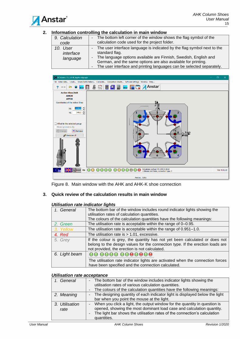
Figure 8. Main window with the AHK and AHK-K shoe connection
3. Quick review of the calculation results in main window Utilisation rate indicator lights
1. General The bottom bar of the window includes round indicator lights showing the utilisation rates of calculation quantities. The colours of the calculation quantities have the following meanings:
2. Green The utilisation rate is acceptable within the range of 0–0.95.
3. Yellow The utilisation rate is acceptable within the range of 0.951–1.0.
4. Red The utilisation rate is > 1.01, excessive.
5. Grey If the colour is grey, the quantity has not yet been calculated or does not belong to the design values for the connection type. If the erection loads are not provided, the erection is not calculated.
6. Light beam
The utilisation rate indicator lights are activated when the connection forces have been specified and the connection calculated.
Utilisation rate acceptance
1. General - The bottom bar of the window includes indicator lights showing the utilisation rates of various calculation quantities.
- The colours of the calculation quantities have the following meanings:
2. Meaning - The designing quantity of each indicator light is displayed below the light bar when you point the mouse at the light.
3. Utilisation rate
- When you click a light, the output window for the quantity in question is opened, showing the most dominant load case and calculation quantity.
- The light bar shows the utilisation rates of the connection’s calculation quantities.

AHK Column Shoes User Manual
16
User Manual AHK Column Shoes Revision 1/2020
4. Acceptance - When all the lights are green, yellow or grey, - the connection has been accepted. - A red light means that the utilisation rate has been exceeded. - The final acceptance is the responsibility of the engineer.
Shoe code and reinforcement in the area affected by the shoe
5. Raster area - When you have performed the calculation and click the raster area of the shoe, the shoe is activated, and the software shows the shoe and bolt type and the bolt’s coordinate.
6. Dash dot line area
- A dashed line polygon appears around the active shoe, encircling the pieces of rebar that belong to the column reinforcement to which the forces are transferred from the shoe bonds.
- Window 2/4 shows the same situation on a shoe-specific basis. - The shoe’s reinforcement must be located inside the area.
5.3 Design of shoe connection
5.3.1 Project folder and calculation code 1. General
This user manual presents the initial data necessary for calculating shoe connections as well as the shoe calculation results. The instructions for bolt calculations are provided in the Rebar Bolts user manual.
2. Project folder
1. General
- Start the calculation by creating a project folder in which the calculation code and files are saved.
- The user manuals provide a more detailed description of the software’s initial data for calculation and calculation methods as well as the calculation theory and results.
- This user manual only provides connection-specific information.
2. Calculation code selection
- Start by creating a project folder in the File/Project folder menu. - The software prompts you to select the country-specific calculation code to
be copied to the folder and used for calculating the file in the folder. The code is selected once for each new folder.
- The calculation will use the code selected in this folder. - You can change the code by creating a new folder and selecting another
code for it.
3. Project information
- In these fields, you provide general information about the project. - This will be output at the beginning of the calculation file.
3. Calculation code
EN 1992-1-1:2004 and EN 1992-4:2018 Basic Eurocode and the latest part, no. 4
SFS-EN 1992-1-1:2005+NA Finnish Eurocode + NA
SS-EN 1992-1-1:2005/AC:2010+A1/2014 + EKS 11 Swedish Eurocode + EKS 11
DIN-EN 1992-1-1:2011-01+A1/2014 German Eurocode + NA
4. Project information:
In these fields, you provide general information about the project in the folder. This will be printed at the beginning of each calculation printout.
5. Print
1. Printing - To print the calculation on paper, select the information you wish to print. - The print job is sent to the default printer selected.
- The printout language is selected from the menu.

AHK Column Shoes User Manual
17
User Manual AHK Column Shoes Revision 1/2020
5.3.2 Selecting the connection type and materials
1. Selecting the connection
1. Connection type
- Select column joint connection by choosing Connection selection from the Initial data menu.
- The menu shown in Figure 9 opens in the window, showing the connection types available in the software.
- The connection type is selected first. - The selection adjusts the software’s main window and other windows
according to the connection selected.
2. Calculation code
- Select the calculation code for the Rebar bolts from the window. - The default code is EN 1992-4:2018, and the calculation can also be
performed using the older CEN/TS 1992-4:2018 standard, which provides slightly more conservative calculation results.
2. Connection type for column shoes
1. Column - Column - A connection between two columns, where the lower column may be the same size or larger. Select square, rectangular or circular as the column shape. The location is either in the center or with the selected edges tangential to one another.
2. Column -Foundation column
- A connection between a column and a foundation column, where the foundation column may be the same size or larger. The location is either in the center or with the edges tangential to one another.
3. Column - Foundation footing
- A connection between a column and a cast-in-situ footing. The location is in the center.
Figure 9. ACOLUMN software connection types
5.3.3 Initial data
1. Menu bar structure 1. Menu bar - The initial data for the Column shoe connection, structure of the
connection and materials are provided in the Initial data menu, which includes six tabs.
2. Initial values - We recommend entering the initial data in the right order, either by changing the values or accepting the default values.
- This adjusts the other tabs and their calculation parameters.
3. Acceptance - When you click Accept, the selection updates the main window according to the dimensions selected.
AHK Column Shoes User Manual
18
User Manual AHK Column Shoes Revision 1/2020
2. Calculation ID, tab1 The identifying information output in the calculations is entered in the fields.
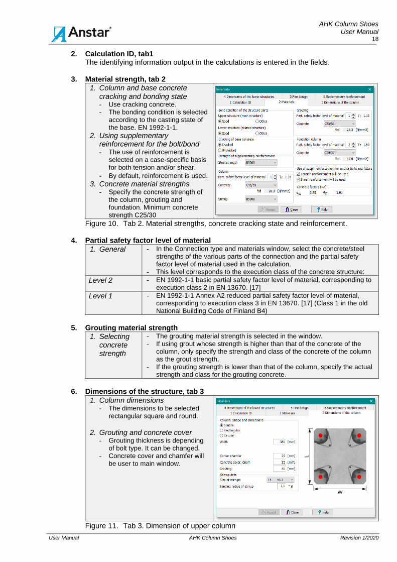
3. Material strength, tab 2
1. Column and base concrete cracking and bonding state - Use cracking concrete. - The bonding condition is selected
according to the casting state of the base. EN 1992-1-1.
2. Using supplementary reinforcement for the bolt/bond - The use of reinforcement is
selected on a case-specific basis for both tension and/or shear.
- By default, reinforcement is used. 3. Concrete material strengths
- Specify the concrete strength of the column, grouting and foundation. Minimum concrete strength C25/30
Figure 10. Tab 2. Material strengths, concrete cracking state and reinforcement.
4. Partial safety factor level of material
1. General - In the Connection type and materials window, select the concrete/steel strengths of the various parts of the connection and the partial safety factor level of material used in the calculation.
- This level corresponds to the execution class of the concrete structure:
Level 2 - EN 1992-1-1 basic partial safety factor level of material, corresponding to execution class 2 in EN 13670. [17]
Level 1 - EN 1992-1-1 Annex A2 reduced partial safety factor level of material, corresponding to execution class 3 in EN 13670. [17] (Class 1 in the old National Building Code of Finland B4)
5. Grouting material strength
1. Selecting concrete strength
- The grouting material strength is selected in the window. - If using grout whose strength is higher than that of the concrete of the
column, only specify the strength and class of the concrete of the column as the grout strength.
- If the grouting strength is lower than that of the column, specify the actual strength and class for the grouting concrete.
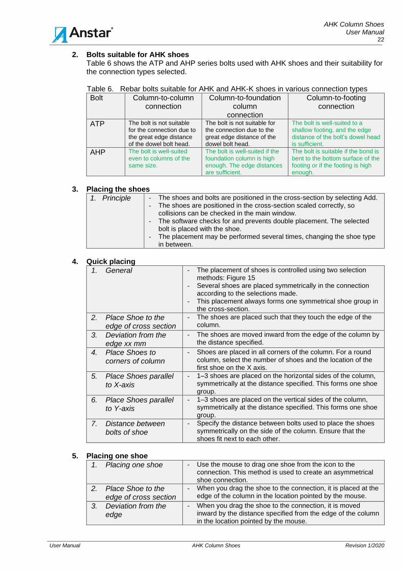
6. Dimensions of the structure, tab 3
1. Column dimensions - The dimensions to be selected
rectangular square and round.
2. Grouting and concrete cover
- Grouting thickness is depending of bolt type. It can be changed.
- Concrete cover and chamfer will be user to main window.
Figure 11. Tab 3. Dimension of upper column

AHK Column Shoes User Manual
19
User Manual AHK Column Shoes Revision 1/2020
7. Dimensions of the foundation structures, tab 4
1. Foundation dimensions - Dimensions of foundation is given
according to pictures. - The column can be placed such
that it touches the edge of the foundation. Resistances are always calculated with the placement.
2. Corner bevel and stirrup. - This only influences the graphics in
the main window.
Figure 12. Tab 4. Selecting the base dimensions
8. Fire design, tab 5
1. Calculation principle
- For fire design, select the fire resistance time and fire treatment method for the parts of the connection.
- This data will be output in the strength calculations as selected. - The treatment methods available are:
2. Column shoe
- The shoe bonds and their welds are protected by a 45 mm concrete cover that corresponds to fire resistance requirement A120.
- The shoe base plate is positioned such that it is protected by concrete pouring on the outside.
- Another option is to position the shoes inward so that the fire protection of the base plate is provided by the grouting.
3. Grouting cross section
- The bolts are protected by a sufficient concrete cover at the grouting. - The software will soon feature a function for calculating the fire
resistance of the shoe’s base plate casting according to the actual situation.
4. Adjoining structure
- The foundation bolts are always protected by an adequate concrete cover.
5. Choosing fire resistance
Figure 13. Tab 5. Selecting the fire resistance method for the column connection

AHK Column Shoes User Manual
20
User Manual AHK Column Shoes Revision 1/2020
9. Supplementary reinforcement, tab 6
1. Supplementary reinforcement - The size of the anchor bolts
reinforcement can be selected on Tab 6. - The window shows the reinforcing units
available for each connection type. - The reinforcement principle drawing can
be opened by clicking the Ast code. - The software calculates the amount of
supplementary reinforcement with the selected rebar size.
- The default rebar size selected is output to the calculation file.
Figure 14. Tab 6. Size of supplementary reinforcement
10. Accepting the initial data
1. Acceptance - All calculation data that has been selected/modified must be accepted by clicking the Accept button.
- The button accepts all the tabs of the Initial data window at the same time.
2. Changes - The dimensions and materials can be changed and tried out quickly between calculations.
5.3.4 Calculation forces
1. Combining the calculation forces for the connection
1. Defining forces - The calculation forces for the connection are first calculated using a separate statistics application.
- These results are used to form the combinations of forces, from which the most dominant forces are provided as initial data.
- The forces to be provided already include the partial safety factors of loads in accordance with the calculation code.
2. Erection state - Three combinations of forces are provided for the connection in situations in which the column has been erected and the connection has not been grouted yet.
3. Ultimate limit state (ULS)
- A maximum of eight combinations of forces may be provided for the connection for the ultimate limit state.
4. Accidental limit state (ALS)
- A maximum of eight combinations of forces may be provided for the connection for accidental limit states.
5. Design forces of connection The calculation forces for the connection
are: - N = Column’s axial force. The
compressive force is negative. - Mx, My = Column bending moments in
relation to the axes, positive direction as shown in the figure.
- Qx, Qy = Shear forces positive in the direction of the axes.
The calculation forces affect at the level of the shoe base plate. The same rules of signs apply to the erection state.

AHK Column Shoes User Manual
21
User Manual AHK Column Shoes Revision 1/2020
6. Forces on erection state
7. Forces on ultimate limit state (ULS)
Figure 15. Forces on the connection during the erection state and ultimate limit state
2. Transferring the connection’s shear force
1. General - Two functional options are available for transferring the connection’s shear force.
2. Friction force will be used to transfer shear force
- The shear force is transferred through the friction of the column and the compressed bottom surface of the shoe base plate to the grouting and from there to the concrete of the foundations.
- The bolts do not take part in transferring the shear force. This method can be used to transfer greater shear forces, if the proportion of the column’s compressive axial force is sufficient.
- The software checks the sufficiency of the friction force and transfers the rest of the shear force through the bolts if the friction is insufficient.
3. Friction force will not be used to transfer shear force
- The shear force is transferred from the column through the edge compression of the shoe base plate hole to the bolt, from which the shear force is transferred through the bolt to the foundations.
3. Approving the calculation forces
1. Acceptance - All forces that have been provided or modified must be accepted by clicking the Accept button before calculation.
5.3.5 Placing the shoes and bolts in the connection
1. Placing the shoes
1. General - The shoes and bolts are positioned in the connection using the menus shown on the right in Figure 15.
- The menu can be opened by selecting Shoes/Bolts/Rebars.../Place Shoes/Select Column Shoe, under which you select the AHK shoe.
2. Selecting the shoes and
bolts: - When the shoe has been
selected, the bolts suitable for the AHK shoe will be available in the bolt menu.
- Only the ATP and AHP
series bolts that are suitable for the shoe will be available for selection.
3. Selecting the column rebar: - When the rebar for the
column has been selected, the size of the rebar to be positioned in the column.
Figure 16. Windows for placing the shoes, bolts and column’s main pieces of rebar
AHK Column Shoes User Manual
22
User Manual AHK Column Shoes Revision 1/2020
2. Bolts suitable for AHK shoes Table 6 shows the ATP and AHP series bolts used with AHK shoes and their suitability for the connection types selected.
Table 6. Rebar bolts suitable for AHK and AHK-K shoes in various connection types
Bolt
Column-to-column connection
Column-to-foundation column
connection
Column-to-footing connection
ATP The bolt is not suitable for the connection due to the great edge distance of the dowel bolt head.
The bolt is not suitable for the connection due to the great edge distance of the dowel bolt head.
The bolt is well-suited to a shallow footing, and the edge distance of the bolt’s dowel head is sufficient.
AHP The bolt is well-suited even to columns of the same size.
The bolt is well-suited if the foundation column is high enough. The edge distances are sufficient.
The bolt is suitable if the bond is bent to the bottom surface of the footing or if the footing is high enough.
3. Placing the shoes
1. Principle - The shoes and bolts are positioned in the cross-section by selecting Add. - The shoes are positioned in the cross-section scaled correctly, so
collisions can be checked in the main window. - The software checks for and prevents double placement. The selected
bolt is placed with the shoe. - The placement may be performed several times, changing the shoe type
in between.
4. Quick placing
1. General - The placement of shoes is controlled using two selection methods: Figure 15
- Several shoes are placed symmetrically in the connection according to the selections made.
- This placement always forms one symmetrical shoe group in the cross-section.
2. Place Shoe to the edge of cross section
- The shoes are placed such that they touch the edge of the column.
3. Deviation from the edge xx mm
- The shoes are moved inward from the edge of the column by the distance specified.
4. Place Shoes to corners of column
- Shoes are placed in all corners of the column. For a round column, select the number of shoes and the location of the first shoe on the X axis.
5. Place Shoes parallel to X-axis
- 1–3 shoes are placed on the horizontal sides of the column, symmetrically at the distance specified. This forms one shoe group.
6. Place Shoes parallel to Y-axis
- 1–3 shoes are placed on the vertical sides of the column, symmetrically at the distance specified. This forms one shoe group.
7. Distance between bolts of shoe
- Specify the distance between bolts used to place the shoes symmetrically on the side of the column. Ensure that the shoes fit next to each other.
5. Placing one shoe
1. Placing one shoe - Use the mouse to drag one shoe from the icon to the connection. This method is used to create an asymmetrical shoe connection.
2. Place Shoe to the edge of cross section
- When you drag the shoe to the connection, it is placed at the edge of the column in the location pointed by the mouse.
3. Deviation from the edge
- When you drag the shoe to the connection, it is moved inward by the distance specified from the edge of the column in the location pointed by the mouse.

AHK Column Shoes User Manual
23
User Manual AHK Column Shoes Revision 1/2020
6. Viewing/removing and moving shoes
1. General - The shoe cross-section can be made symmetrical or asymmetrical, and various shoes can be located on different sides of the cross-section.
- The location of one shoe or all shoes may be freely changed using the following functions: (Close the Shoes/Bolts/Rebars... window before using this function.)
2. Active Shoe/Bolt
- To view the shoe and bolt information, make the shoe active by clicking its raster area in the main window; this changes the colour of the shoe/bolt selected and displays its information in the top left corner of the main window.
- The image of the selected, active shoe and bolt is shown on the left side of the window.
- The selected shoe’s coordinates from the origin of the cross-section are shown in the window.
- The selection shows all the other shoes belonging to the same group with a different raster colour.
3. Remove - This function only removes the active shoe and bolt from the group.
4. Remove all - This function removes all shoes and bolts that belong to the active group.
5. Change - First, select one shoe to make it active. - Change the coordinates of the shoe to the extent that you want to
move it. - The Change function moves the selected shoe to the new
coordinates.
6. Change/Affect the selected group
- The Change function moves all the shoes in the group in the horizontal/vertical direction according to the relative displacement selected. Moves the entire group linearly.
7. Change/Move symmetrically
- The Change function moves all the shoes in the group symmetrically in relation to the main axes by the distance selected. Moves the entire group symmetrically.
5.3.6 Placing the rebar in the connection 1. Placing the main pieces of rebar for the column
1. Principle - The main pieces of rebar for the column are placed in the connection using the menu shown in Figure 15.
- The pieces of rebar are positioned in the cross-section scaled correctly, so collisions can be checked in the main window.
- The software checks for and prevents double placement. - The placement may be performed several times, changing the
rebar size in between.
2. Quick placing
1. General - Several pieces of rebar are placed symmetrically in the connection according to the selections made.
- This placement always forms one symmetrical rebar group in the cross-section.
2. Place Rebars to corners of column
- The pieces of rebar are placed in the corners of the column. There may be 1–5 pieces of rebar per corner, and they are placed symmetrically at the specified distance from each other. For a round column, select the total number of pieces of rebar and the location of the first piece on the X axis.
3. Free distance between rebars
- This option is used to adjust the free distance between the pieces of rebar in the corner of the column. The default distance is the low limit for the bundle property of the rebar selected.
4. Place Rebars parallel to X-axis
- 1–99 pieces of rebar are placed on the horizontal sides of the column, symmetrically at the c/c distance specified. This forms one rebar group.
5. Place Rebars - 1–99 pieces of rebar are placed on the vertical sides of the column,
AHK Column Shoes User Manual
24
User Manual AHK Column Shoes Revision 1/2020
parallel to Y-axis symmetrically at the c/c distance specified. This forms one rebar group.
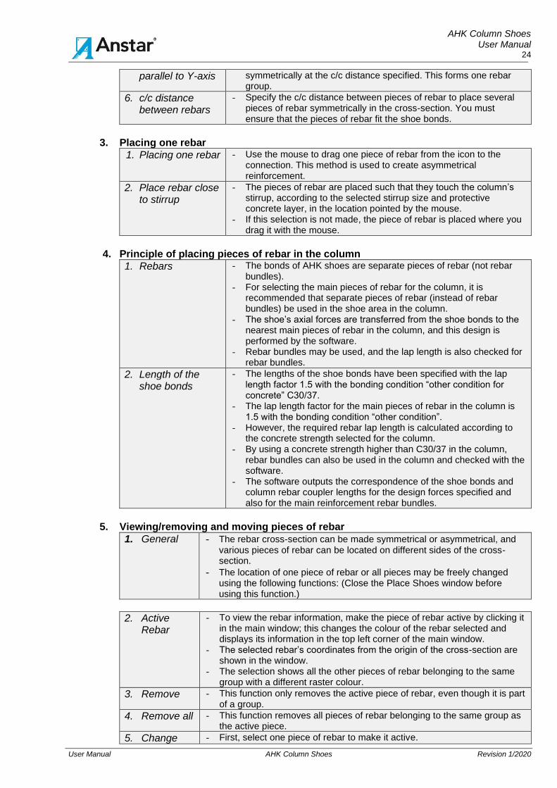
6. c/c distance between rebars
- Specify the c/c distance between pieces of rebar to place several pieces of rebar symmetrically in the cross-section. You must ensure that the pieces of rebar fit the shoe bonds.
3. Placing one rebar
1. Placing one rebar - Use the mouse to drag one piece of rebar from the icon to the connection. This method is used to create asymmetrical reinforcement.
2. Place rebar close to stirrup
- The pieces of rebar are placed such that they touch the column’s stirrup, according to the selected stirrup size and protective concrete layer, in the location pointed by the mouse.
- If this selection is not made, the piece of rebar is placed where you drag it with the mouse.
4. Principle of placing pieces of rebar in the column
1. Rebars - The bonds of AHK shoes are separate pieces of rebar (not rebar bundles).
- For selecting the main pieces of rebar for the column, it is recommended that separate pieces of rebar (instead of rebar bundles) be used in the shoe area in the column.
- The shoe’s axial forces are transferred from the shoe bonds to the nearest main pieces of rebar in the column, and this design is performed by the software.
- Rebar bundles may be used, and the lap length is also checked for rebar bundles.
2. Length of the shoe bonds
- The lengths of the shoe bonds have been specified with the lap length factor 1.5 with the bonding condition “other condition for concrete” C30/37.
- The lap length factor for the main pieces of rebar in the column is 1.5 with the bonding condition “other condition”.
- However, the required rebar lap length is calculated according to the concrete strength selected for the column.
- By using a concrete strength higher than C30/37 in the column, rebar bundles can also be used in the column and checked with the software.
- The software outputs the correspondence of the shoe bonds and column rebar coupler lengths for the design forces specified and also for the main reinforcement rebar bundles.
5. Viewing/removing and moving pieces of rebar
1. General - The rebar cross-section can be made symmetrical or asymmetrical, and various pieces of rebar can be located on different sides of the cross-section.
- The location of one piece of rebar or all pieces may be freely changed using the following functions: (Close the Place Shoes window before using this function.)
2. Active Rebar
- To view the rebar information, make the piece of rebar active by clicking it in the main window; this changes the colour of the rebar selected and displays its information in the top left corner of the main window.
- The selected rebar’s coordinates from the origin of the cross-section are shown in the window.
- The selection shows all the other pieces of rebar belonging to the same group with a different raster colour.
3. Remove - This function only removes the active piece of rebar, even though it is part of a group.
4. Remove all - This function removes all pieces of rebar belonging to the same group as the active piece.
5. Change - First, select one piece of rebar to make it active.
AHK Column Shoes User Manual
25
User Manual AHK Column Shoes Revision 1/2020
- Change the coordinates of the piece of rebar to the extent that you want to move it.
- The Change function moves one piece of rebar to the new coordinates.
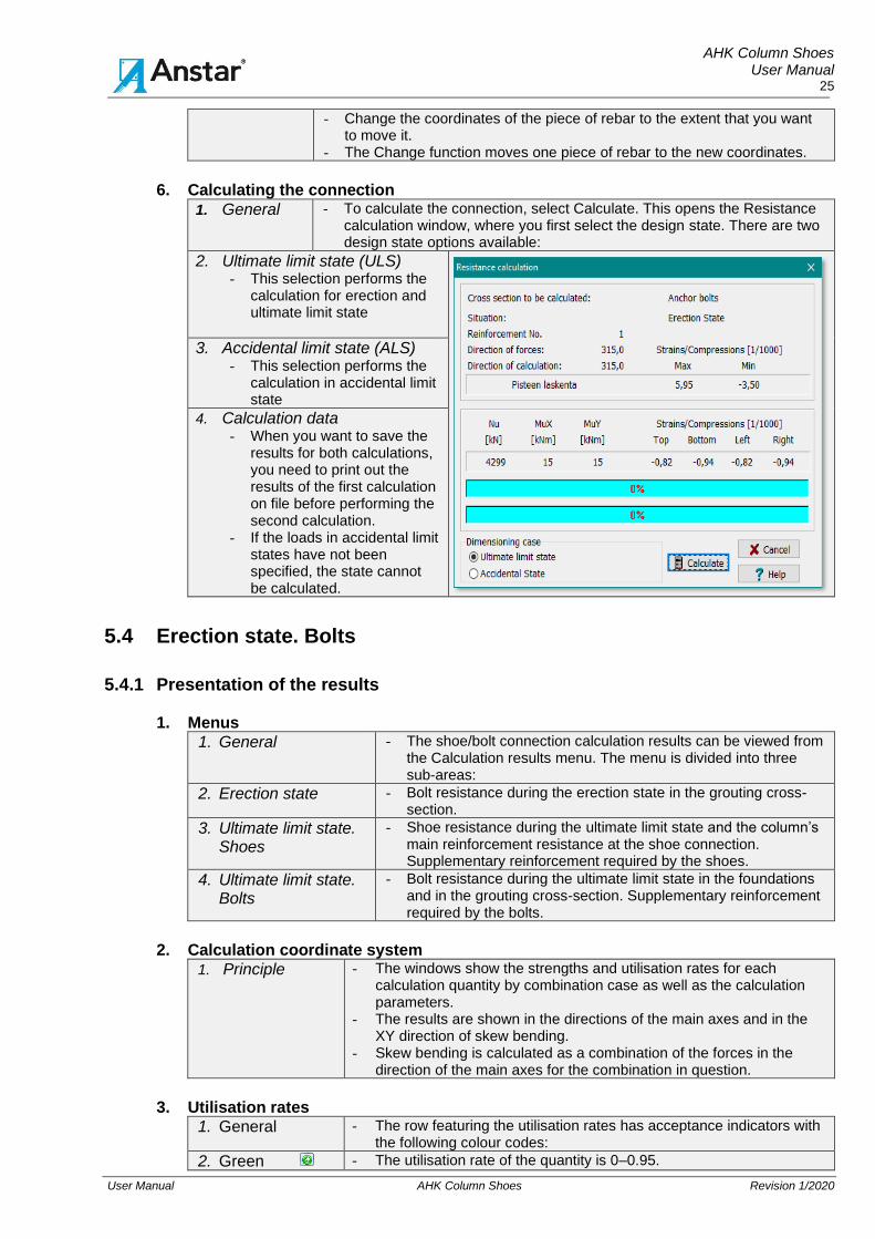
6. Calculating the connection
1. General - To calculate the connection, select Calculate. This opens the Resistance calculation window, where you first select the design state. There are two design state options available:
2. Ultimate limit state (ULS) - This selection performs the
calculation for erection and ultimate limit state
3. Accidental limit state (ALS) - This selection performs the
calculation in accidental limit state
4. Calculation data
- When you want to save the results for both calculations, you need to print out the results of the first calculation on file before performing the second calculation.
- If the loads in accidental limit states have not been specified, the state cannot be calculated.
5.4 Erection state. Bolts
5.4.1 Presentation of the results 1. Menus
1. General - The shoe/bolt connection calculation results can be viewed from the Calculation results menu. The menu is divided into three sub-areas:
2. Erection state - Bolt resistance during the erection state in the grouting cross-section.
3. Ultimate limit state. Shoes
- Shoe resistance during the ultimate limit state and the column’s main reinforcement resistance at the shoe connection. Supplementary reinforcement required by the shoes.
4. Ultimate limit state. Bolts
- Bolt resistance during the ultimate limit state in the foundations and in the grouting cross-section. Supplementary reinforcement required by the bolts.
2. Calculation coordinate system
1. Principle - The windows show the strengths and utilisation rates for each calculation quantity by combination case as well as the calculation parameters.
- The results are shown in the directions of the main axes and in the XY direction of skew bending.
- Skew bending is calculated as a combination of the forces in the direction of the main axes for the combination in question.
3. Utilisation rates
1. General - The row featuring the utilisation rates has acceptance indicators with the following colour codes:
2. Green - The utilisation rate of the quantity is 0–0.95.

AHK Column Shoes User Manual
26
User Manual AHK Column Shoes Revision 1/2020
3. Yellow - The utilisation rate of the quantity is 0.951–1.00.
4. Red - The utilisation rate of the quantity is > 1.00.
5. Grey - The quantity has not been calculated or does not belong to the shoe’s design values.
6. Maximum utilisation rate of the quantity
- Clicking an indicator light opens a window showing the combination case for the maximum utilisation rate.
- Excess values can be found easily, and also the maximum acceptable utilisation rate for each quantity and the combination in which it occurs.
4. Numbering of the structures
1. Principle - After the calculation, numbers will be displayed in the main window at the bolt and shoe bonds and the column’s main pieces of rebar.
- These numbers will be displayed next to the corresponding part/row in the printout windows.
- The information on the printout row can be traced to a structure in the main window.
- The numbers will be displayed after the calculation
5.4.2 Erection state resistance of bolts
1. Resistance values and acceptance
1. Design loads - Design is done according to EN 1992-4:2018, chapter 6.2.2.3. Shear loads with lever arm.
- Connection is calculated for erection state loads. - All loads will be transferred through the bolts. - If erection loads has not been given. Calculation is not performed.
2. Resistance graph of connection. Window 1/1
- In window 1/1 is presented design graphs for erection state of bolts in grouting section for erection state loads.
- Resistance graph of bolts is calculated with compressed and bended structure according to the grouting thickness.
- Calculation is performed to direction of main axis. - Resistance graph is presented as axial force/bending moment
graph and there is not included shear force.
3. Acceptance - Loading points shall be inside the graphs.
4. Resistance of bolts. Window 1/2
- Ikkunassa 1/2 on liitoksen pulttien asennustilanteen kestävyys. - Pultti mitoitetaan normaalivoiman, momentin ja leikkauksen
yhteisvaikutukselle.

AHK Column Shoes User Manual
27
User Manual AHK Column Shoes Revision 1/2020
5. Acceptance - The resistance of bolts is adequate if utilization ratios are on
acceptable levers. - In the window 1/2 there is design parameters used in calculation.
Figure 17. Erection state. Axial and shear force resistance of bolt.
5.5 Ultimate limit state. Shoes
5.5.1 Shoes’ resistance. Axial force 1. Calculation principle
1. Principle - The calculation results for the column and shoes during the ultimate limit state are indicated using four indicator lights in the bottom bar. (Lights 3–6.) Drop-down menu Calculation results/Ultimate limit State/shoes. Printout menus 2/1–2/5.
- NOTE: Accidental limit state calculation is selected from the Calculate menu. In this case, the calculation results presented in sections 5.5 and 5.6 apply to design for accidental limit states. The texts on the windows and menus also change accordingly:
2. Window 2/1. Axial force resistance of shoe to bending direction.
1. Results - The calculation forces and axial force resistance of shoe are displayed by combination case as shown in Figure 18.
2. Utilization degree
- The utilization rates are calculated in the directions of the main axes and combined for skew bending.
- If resistance exceed change shoe or increase concrete strength.
3. Resistance
Figure 18. Ultimate limit state. Axial forces resistance and utilisation rate of shoe.
AHK Column Shoes User Manual
28
User Manual AHK Column Shoes Revision 1/2020
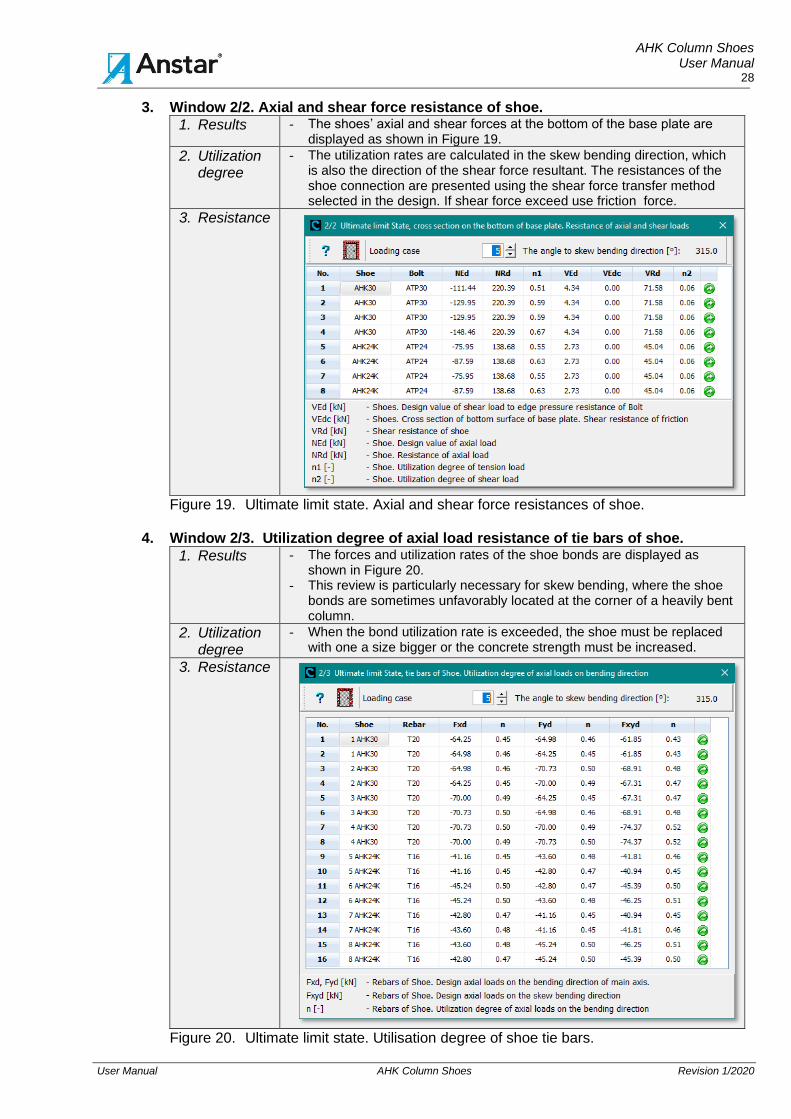
3. Window 2/2. Axial and shear force resistance of shoe.
1. Results - The shoes’ axial and shear forces at the bottom of the base plate are displayed as shown in Figure 19.
2. Utilization degree
- The utilization rates are calculated in the skew bending direction, which is also the direction of the shear force resultant. The resistances of the shoe connection are presented using the shear force transfer method selected in the design. If shear force exceed use friction force.
3. Resistance
Figure 19. Ultimate limit state. Axial and shear force resistances of shoe.
4. Window 2/3. Utilization degree of axial load resistance of tie bars of shoe.
1. Results - The forces and utilization rates of the shoe bonds are displayed as shown in Figure 20.
- This review is particularly necessary for skew bending, where the shoe bonds are sometimes unfavorably located at the corner of a heavily bent column.
2. Utilization degree
- When the bond utilization rate is exceeded, the shoe must be replaced with one a size bigger or the concrete strength must be increased.
3. Resistance
Figure 20. Ultimate limit state. Utilisation degree of shoe tie bars.
AHK Column Shoes User Manual
29
User Manual AHK Column Shoes Revision 1/2020
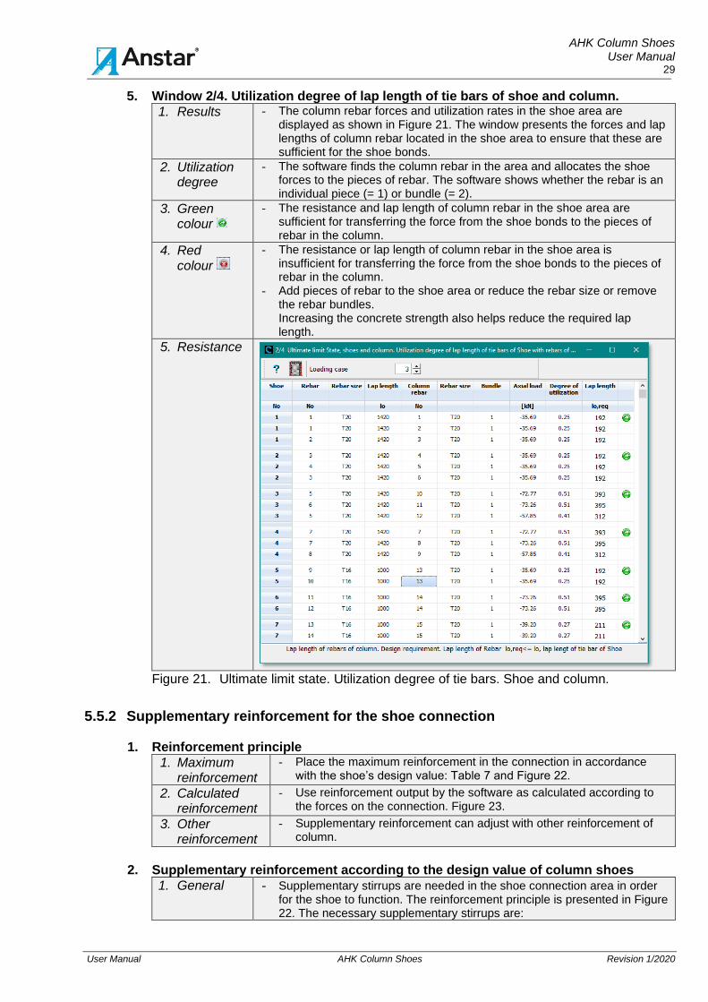
5. Window 2/4. Utilization degree of lap length of tie bars of shoe and column.
1. Results - The column rebar forces and utilization rates in the shoe area are displayed as shown in Figure 21. The window presents the forces and lap lengths of column rebar located in the shoe area to ensure that these are sufficient for the shoe bonds.
2. Utilization degree
- The software finds the column rebar in the area and allocates the shoe forces to the pieces of rebar. The software shows whether the rebar is an individual piece (= 1) or bundle (= 2).
3. Green colour
- The resistance and lap length of column rebar in the shoe area are sufficient for transferring the force from the shoe bonds to the pieces of rebar in the column.
4. Red colour
- The resistance or lap length of column rebar in the shoe area is insufficient for transferring the force from the shoe bonds to the pieces of rebar in the column.
- Add pieces of rebar to the shoe area or reduce the rebar size or remove the rebar bundles. Increasing the concrete strength also helps reduce the required lap length.
5. Resistance
Figure 21. Ultimate limit state. Utilization degree of tie bars. Shoe and column.
5.5.2 Supplementary reinforcement for the shoe connection
1. Reinforcement principle
1. Maximum reinforcement
- Place the maximum reinforcement in the connection in accordance with the shoe’s design value: Table 7 and Figure 22.
2. Calculated reinforcement
- Use reinforcement output by the software as calculated according to the forces on the connection. Figure 23.
3. Other reinforcement
- Supplementary reinforcement can adjust with other reinforcement of column.
2. Supplementary reinforcement according to the design value of column shoes
1. General - Supplementary stirrups are needed in the shoe connection area in order for the shoe to function. The reinforcement principle is presented in Figure 22. The necessary supplementary stirrups are:

AHK Column Shoes User Manual
30
User Manual AHK Column Shoes Revision 1/2020
Ast1 - Vertical stirrups 1 + 1 pc. are placed on both sides of the shoe, and the stirrups transfer the shoe’s shear force during the erection state and ultimate limit state in accordance with Section 4.2.2.
- However, at least the minimum number of stirrups 1 + 1 pc. according to Table 7 is always placed symmetrically on both sides of the shoe. The number of stirrups increases if the shear force so requires.
- For a round column, the stirrups are placed in the diameter direction of the column.
- The stirrup anchoring length begins from above the shoe housing.
Ast2 - The stirrups bind the horizontal forces caused by the eccentric axial force of the shoe.
- The stirrups are placed immediately above the shoe housing as a bundle. Table 7.
- Circular stirrups are placed above the shoe for a round column and closed stirrups for a rectangular column.
Ast3 - The stirrups are located at the bottom and top ends of the shoe bonds according to EN 1992-1-1, Section 8.7.3.1.
- The stirrups are needed when the shoe’s bond or column’s main piece of rebar is in the shoe area ≥ T20.
- The distance between stirrups/location area is ≤ 150 mm. - The number of stirrups/location area = Ast3, which has been calculated according
to the size of the shoe’s bond.
Figure 22. Supplementary reinforcement for AHK and AHK-K shoes.
1. General - Table 7 presents the supplementary reinforcement for the shoe connection as calculated for the shoe’s resistance values.
- At least these stirrups must be placed in the column. - If the connection includes shoes of different sizes, the number of
stirrups is determined according to the largest shoe. - The stirrup size can be changed and adapted to the other stirrup
reinforcement of the column.
Table 7. Supplementary reinforcement for shoes with the shoe design values
Shoe Ast1 Ast2 Ast3 Shoe Ast1 Ast2 Ast3 T T mm2 T T mm2
AHK16 2T8 T8 – AHK16K 2T8 T8 – AHK20 2T8 T8 – AHK20K 2T8 T8 – AHK24 2T8 2T8 – AHK24K 2T8 T8 – AHK30 2T8 2T8 157 AHK30K 2T8 T8 157 AHK36 2T10 3T8 245 AHK36K 2T10 T8 245 AHK39 2T10 2T10 245 AHK39K 2T10 2T8 245 AHK45 2T12 3T10 308 AHK45K 2T12 2T8 308

AHK Column Shoes User Manual
31
User Manual AHK Column Shoes Revision 1/2020
3. Supplementary reinforcement according to the calculation value of column shoes
1. General - The software calculates the supplementary reinforcement required by the shoes according to the shoe structure and the forces on the connection. This information is output in Window 2/5. Figure 23. The reinforcement principle is in accordance with Figure 22.
2. Supplementary reinforcement - The number of supplementary stirrups
Ast1 is at least the minimum number according to Table 7 with the stirrup size selected. The number of stirrups is also calculated on the basis of the shear force on the connection if this causes a greater need for stirrups.
- The number of stirrups is determined by the connection’s largest corner
- The number of stirrups Ast3 is in accordance with the minimum number in Table 7 with the stirrup size selected in the software.
Figure 23. Supplementary reinforcement calculated for the shoe connection.
5.6 Ultimate limit state. Rebar bolts
5.6.1 Resistance graph for the column and grouting cross-section 1. Calculation results
1. General - The calculation results for bolts are presented in windows 3/1–3/6, which you can open by selecting Calculation results/3 Ultimate limit state/Bolts. The indicator light bar at the bottom of the main window can be used to display the most dominant combination case and the other
2. Resistance graphs
- The resistance graphs for column shoe connections and the combination case loading points at the connection are shown in printout window 3/1. The shoe connection is acceptable if the following criteria are met:
3. Blue graph - The column’s axial force/bending moment resistance graph without the effect of slenderness in the main reinforcement of the shoe area and with the calculation strength of the concrete of the column. The blue graph must be located outside the green graph.
- The blue graph may very locally intersect the green bolt graph.
4. Green graph - The bolts’ resistance graph at the grouting intersection calculated with the tensile resistance of the bolt’s thread and the calculation strength of the grouting concrete. The effect of shear force is not included.
5. Loading points - Ultimate limit state loading points C1–C8 must be located inside the green graph.
- The relative distance of loading points C1–C8 from the green graph represents the level of the connection’s utilisation rate.
6. Red dashed line - The loading points must not be located in the area of the peak of the graph, which is left outside the line. EN 1990, section 2.2(3).
2. Resistance graph. Calculation method
1. Calculation - The axial force resistance graphs are printed out in the bending direction of the main axes Mx and My and in the skew bending direction Mxy, whose direction angle is determined by the ratio of bending moments Mx/My. Figure 24.
2. Presentation - Upper part of x-axis graphs are compressed column. - Lower part of x-axis graphs are tensioned column.

AHK Column Shoes User Manual
32
User Manual AHK Column Shoes Revision 1/2020
3. Graphs
Figure 24. Ultimate limit state. Resistance graph and loading points, main axis direction.
5.6.2 Stress state of the column’s grouting cross-section
1. Calculation of stress state
1. Calculation - In Window 3/1 (Tab 2), the software outputs the failure force/stress/deformation and utilisation rates of the materials of the column cross-section by load case in the skew bending direction.
- The calculation is performed in the grouting cross-section.
2. Grouting cross section. Concrete stress, 2D picture
2. Concrete calculation element The information of an individual concrete element can be viewed by clicking the element with the mouse.
- Grey: The concrete is in tension. - Other colours: The compressive stress of the concrete is in
the range 0 < fc ≤ fck. - The software calculates the compression εc of the concrete. - Yellow: The calculation stress fc of the concrete exceeds its
compressive strength fck. - Utilisation rate of the compressive strength of the concrete
fc/fck.
3. Bolt calculation element The information of an individual bolt can be viewed by clicking the calculation element with the mouse.
Figure 25. Ultimate limit state. Stress/deformation of the grouting cross-section. 3. Grouting cross section. Concrete stress, 3D picture
1. Results - Tab 3 of window 3/1 shows the stress distribution of the grouting used in the calculation at the end of the column as a 3D diagram along with the material calculation values.
- The diagram shows concrete in tension and concrete in yield as horizontal areas.

AHK Column Shoes User Manual
33
User Manual AHK Column Shoes Revision 1/2020
2. 3D stress figure
Figure 26. Ultimate Limit State. 3D stress state of the grouting cross-section
4. Concrete material δ-ε relation
1. Concrete - Tab 4 of window 3/1 shows the stress/deformation graph of the concrete used in the calculation (column and grouting) as well as the material calculation values.
2. Concrete δ-ε relation graphs
Figure 27. Stress/deformation graph of the column and grouting concrete
5.7 Shoe connection’s service life design 1. Splitting analysis of the anchor plate’s base concrete with the specific loads.
1. Concrete and supplementary reinforcement
The following analysis is performed on the splitting of the anchor plate’s. - Tab 1 of Window 3/6 shows the stress state of the tensile
reinforcement calculated for the anchor plate with specific loads δt,nom. - Tab 3 of Window 3/6 shows the stress state of the shear reinforcement
calculated for the anchor plate with specific loads δt,nom. - The specific load has been determined by dividing the calculation load
by a factor specified with the load ratio factor Gk in the Loads window.
2. Splitting design
- Splitting design is performed for the anchor plate’s base concrete at the edge of the structure by using these stress states as the basis for the calculation along with the structure’s dimensions and other loads.
- The splitting design is performed by applying the instructions in EN 1992-1-1,[6] Section 7.3.

AHK Column Shoes User Manual
34
User Manual AHK Column Shoes Revision 1/2020
2. Recommended concrete covers and surface treatments
1. Hot dip galvanizing
- Anchor bolts can be hot dip galvanized - Only thread can be hot dip galvanized or alternative whole bolt. - The thread of bolt can be removable part and material can be selected
according to corrosion requirements.
2. Concrete cover
- Table 10 shows the nominal value Cnom required for the concrete cover of the shoe’s bonds by exposure class according to minimum value Cmin,cur. The nominal value for the concrete cover of the shoe’s bonds is Cnom = Cmin,cur + ΔCdev (= 5 mm). Table presents the recommended placement of the shoe in the column, assuming that the stirrup diameter is 8 mm for shoes AHK16–AHK36 and 10 mm for shoes AHK39–AHK45. The table shows the recommended surface treatment methods for the shoe in various exposure classes.
- The standard location of APK-CM shoes’ bonds is at a distance of 43–45 mm from the edge of the base plate
3. Structural protection
- The fire protection and structural location of the housing and base plate are utilised in the analysis.
- The following structural protection methods are used for shoes in addition to the required concrete cover:
- Water must be prevented from entering the enclosed structure of the shoe by means of a structural solution.
- In structures exposed to the cold and moisture, the shoes are hot-dip galvanised.
- In structures exposed to chlorides or chemical stress, the shoes are placed more inward in the column.
3. Service life design
4. Codes - Service life and durability design for a column shoe connection is performed according to EN 1992-1-1, [6] Section 4. In addition, the instructions in the EN 13670 [17] standard and Finnish National Annex SFS 5796 can be applied. For element structures, the EN 13369:2018 [19] standard and Finnish National Annex SFS 7026 are applied.
5. Structure - The analysis is performed according to the column’s exposure class separately for the shoe bonds and the housing and base plate.
Table 8. Required nominal value Cnom for the concrete cover.
Exposure class EN
1992-1-1
50 -year
service life
Cnom mm
100-year service
life
Cnom
mm
Shoe placement in
relation to column edge
Recommended surface treatment options for shoes
Surface treatment of bonds
Surface treatment of shoe housing and base plate
X0 15 15 Placed at edge No surface treatment No surface treatment
XC1 15 25 Placed at edge No surface treatment No surface treatment
XC2 25 35 Placed at edge No surface treatment No surface treatment
XC3–XC4 30 40 Placed at edge/more
inward
No surface treatment/ Hot-dip galvanised
No surface treatment/ Hot-dip galvanised
XS1–XD1 35 45 Placed at edge/more
inward
No surface treatment/ Hot-dip galvanised
No surface treatment/ Hot-dip galvanised
XS2–XD2 40 50 Placed more inward
Hot-dip galvanised Hot-dip galvanised
XS3–XD3 45 55 Placed more inward
Hot-dip galvanised Hot-dip galvanised
XA1–XA3 XF1–XF4
– – Placed more inward if
necessary
The shoes may only be used on the basis of site-specific special analyses. The surface treatment of the shoe housing and base plate and the nominal value for the concrete cover of the bonds are determined according to the special requirements of the site.

AHK Column Shoes User Manual
35
User Manual AHK Column Shoes Revision 1/2020
6 SHOE CONNECTION MANUFACTURE AT THE FACTORY
6.1 Shoe delivery, storage and identification The shoes are delivered shrink-wrapped on a pallet. Longer-term storage protected from rain. Hot-dip galvanised shoes are stored outdoors for at least four weeks after the galvanisation. This storage period before casting is necessary to avoid a hydrogen reaction, which would weaken the bond. The shoe type and size can be identified as follows:
The pallet is equipped with identifying information and each shoe with a product label. The shoes can be identified as follows:
- Painted shoes: The size of the shoe is also indicated by the colour code of its base plate. The colour codes are presented in tables 2 and 3.
- Galvanised shoes: Galvanised shoes have no colour code. They are identified by the product label.
6.2 Installing the shoes into the column formwork
1. Assembling a shoe group
- AHK and AHK-K shoes are assembled into a group by welding them together with a piece of rebar or flat steel from the edge of the shoe housing. The distance tolerances of the shoes must be ascertained during welding.
2. Installing a group
- Install the shoe group in a pre-assembled column reinforcement by pushing it in from the end of the reinforcement element.
- The shoe bonds can be tied to the main pieces of rebar in the column. Welding must not be used.
- Install the supplementary stirrup reinforcement at this point. The reinforcement instructions are provided in Section 5.5.2.
- Lift the column reinforcement into the formwork. - Place the edge of the shoe base plate on the surface of the column’s edge,
unless the shoes must be placed more inward according to the plans.
- The bottom surface of the base plate must be against the bottom of the formwork and perpendicular to the column’s longitudinal axis.
3. Fastening - The shoe group is fastened to the end of the formwork from the shoe base plate with a clamp.
- Shoes may also be fastened to the bottom of the column formwork with screws through the bolt holes.
- The shoe group must be fastened to the formwork such that it cannot move during casting.
4. Supplementary reinforcement
- Ensure that the supplementary stirrups required by the shoes have been installed.
- Ensure that the column’s main pieces of rebar in the connection area are in accordance with the plans.
5. Tolerances - The shoe group is installed into the formwork with the following tolerances:
1 Location of the shoe group’s bolt holes in relation to the column centre line ± 2 mm
2 Mutual distance and cross-measure of the shoe group’s bolt holes ± 2 mm
3 Shoe installed against the bottom of the formwork, maximum play –0, +2 mm
4 Shoe installed perpendicular to the column’s longitudinal axis, deviation ± 2 mm/m
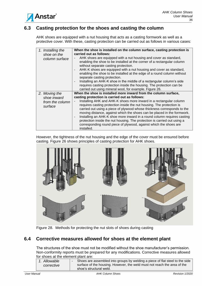
AHK Column Shoes User Manual
36
User Manual AHK Column Shoes Revision 1/2020
6.3 Casting protection for the shoes and casting the column AHK shoes are equipped with a nut housing that acts as a casting formwork as well as a protective cover. With these, casting protection can be carried out as follows in various cases:
1. Installing the shoe on the column surface
When the shoe is installed on the column surface, casting protection is carried out as follows: - AHK shoes are equipped with a nut housing and cover as standard,
enabling the shoe to be installed at the corner of a rectangular column without separate casting protection.
- AHK-K shoes are equipped with a nut housing and cover as standard, enabling the shoe to be installed at the edge of a round column without separate casting protection.
- Installing an AHK-K shoe in the middle of a rectangular column’s side requires casting protection inside the housing. The protection can be carried out using mineral wool, for example. Figure 26.
2. Moving the shoe inward from the column surface
When the shoe is installed more inward from the column surface, casting protection is carried out as follows: - Installing AHK and AHK-K shoes more inward in a rectangular column
requires casting protection inside the nut housing. The protection is carried out using a piece of plywood whose thickness corresponds to the moving distance, against which the shoes can be placed in the formwork.
- Installing an AHK-K shoe more inward in a round column requires casting protection inside the nut housing. The protection is carried out using a corresponding round piece of plywood, against which the shoes are installed.
However, the tightness of the nut housing and the edge of the cover must be ensured before casting. Figure 26 shows principles of casting protection for AHK shoes.
Figure 28. Methods for protecting the nut slots of shoes during casting
6.4 Corrective measures allowed for shoes at the element plant The structures of the shoe must not be modified without the shoe manufacturer’s permission. Non-conformity reports must be prepared for any modifications. Corrective measures allowed for shoes at the element plant are:
1. Allowable corrective
- Shoes are assembled into groups by welding a piece of flat steel to the side surface of the housing. However, the weld must not reach the area of the shoe’s structural weld.

AHK Column Shoes User Manual
37
User Manual AHK Column Shoes Revision 1/2020
measure
- The shoe’s protective housing for casting can be complemented by spot welding or otherwise fastening filler plates to the current housing.
- The filler plates must not restrict the internal size of the casting housing.
- The shoe’s bond may be bent at the top end of the shoe to avoid the structural reservation in the column. The bending is performed using the bending radii and work methods allowed for rebar. Before bending, confirm with the civil engineer that the lap length of the column rebar is sufficient for the new situation.
- The shoe bonds may be slightly bent to make room for the column’s main piece of rebar.
- Column reinforcements may be welded to the shoe bonds, if spot welds are used and the purpose is to fasten the reinforcement/shoe to the formwork during the installation.
- Load-bearing joints must not be welded to the shoe bonds.
The following corrective measures are not allowed. These changes require a separate non-conformity plan and the shoe manufacturer’s approval.
2. Non-allowable corrective measure
- The load-bearing structure of the shoe must not be modified by cutting or welding.
- The shoe bonds must not be cut or shortened. - The shoe bonds must not be bent such that the bending begins at the
bond’s weld.
- No force-bearing parts may be welded to the shoe base plate or bonds.
6.5 Manufacture quality control
Manufacture quality control for column connections is carried out in accordance with the element plant’s quality system and/or any separate element quality control plan prepared for the project. The structural and dimensional inspections specified in the quality system/inspection plan are performed on the shoes. For concrete and shoe connection structures, the instructions provided in EN 13670 are followed. The quality control measures to be performed for shoe connections include:
1. Measures before casting
- Check that the shoe is as planned and not damaged. - Ensure that the shoe group is correctly located in the formwork. - Ensure that the shoe has been securely fastened and the nut slots
protected. - Ensure that the supplementary reinforcement required by the shoes has
been installed.
2. Measures after casting
- Measure the location of the shoe’s bolt holes to correspond to the planned tolerances and check that the casting has been successful, and the shoe is clean.
6.6 Final documentation of manufacture quality control
When the job has been accepted, the element manufacturer is required to provide the client with the inspection and quality control documentation created during manufacture. In addition, the delivery must include any as-built documentation and non-conformity reports made during manufacture.

AHK Column Shoes User Manual
38
User Manual AHK Column Shoes Revision 1/2020
7 INSTALLING THE SHOE CONNECTION ON THE SITE
7.1 Standards and plans to be followed during installation
The following instructions and project plans are to be followed when installing the shoe connection.
1. Standards Implementation breakdown Quality plan
- Installation plan prepared by the frame installer. - Concrete structure implementation breakdown prepared for the project
and site. - Quality inspection plan prepared for the project and site. - EN 13670 Execution of concrete structures [17] - EN 13369 Common rules for precast concrete products [19]
2. Drawings - Installation drawings prepared by the frame designer. - Structure sections and installation details prepared by the frame
designer.
3. Installation instructions
- User manual for AHK shoes, whose sections 7, 8 and 9 apply to installing a shoe connection on the site. [21]
7.2 Bolt elevation and nut torque
Bolts according to Table 9 are used in AHK and AHK-K shoes. The table shows the elevation of the bolts and grouting from the rough cast surface as well as the nut torque. Tightening the nut has been specified according to EN 1090-2:2018, Section 8.5.1, such that preload force Fc,p of the bolt is 50% of the breaking force of the bolt’s thread. The nuts are tightened to the torque Mr,1 = 0.125*d*Fp,c, where Fp,c = 0.5*fub*As. After the tightening, at least one pitch of the bolt’s thread must be visible. The thread dimension must not be lower than this, and a repair plan must be made if this happens.
Table 9. Bolt elevation, grouting thickness and torque for AHK and AHK-K shoes
Shoe Bolt A G Mr,1
mm mm Nm
AHK16, AHK16K ATP16, AHP16 105 50 85 AHK20, AHK20K ATP20, AHP20 115 50 170 AHK24, AHK24K ATP24, AHP24 130 50 290 AHK30, AHK30K ATP30, AHP30 150 50 580 AHK36, AHK36K ATP36, AHP36 170 60 1000 AHK39, AHK39K ATP39, AHP39 180 60 1300 AHK45, AHK45K
ATP45, AHP45
190
65
2000
7.3 Column installation, grouting and fire protection
Preparatory work for installing an element column
1. As-built measurements
- Perform as-built measurement of the location of the bolts. - The frame installer checks/approves the as-built dimension records for
anchor bolts. - The responsibility for the bolt locations is transferred to the installer. - Ensure that the elevation of the top surface of the rough cast foundation is
correct.
2. Inspecting the bolts
- Ensure that the bolt threads are undamaged and clean. - Ensure that the surface treatment of the bolt threads corresponds to the
plans. - Ensure that the removable threaded section of each S-series bolt has
beenlocked. - Ensure that nuts and washers have been used in accordance with the
plans.
3. Measurements - The top surface of the washer of the bolt’s bottom nut is installed level with
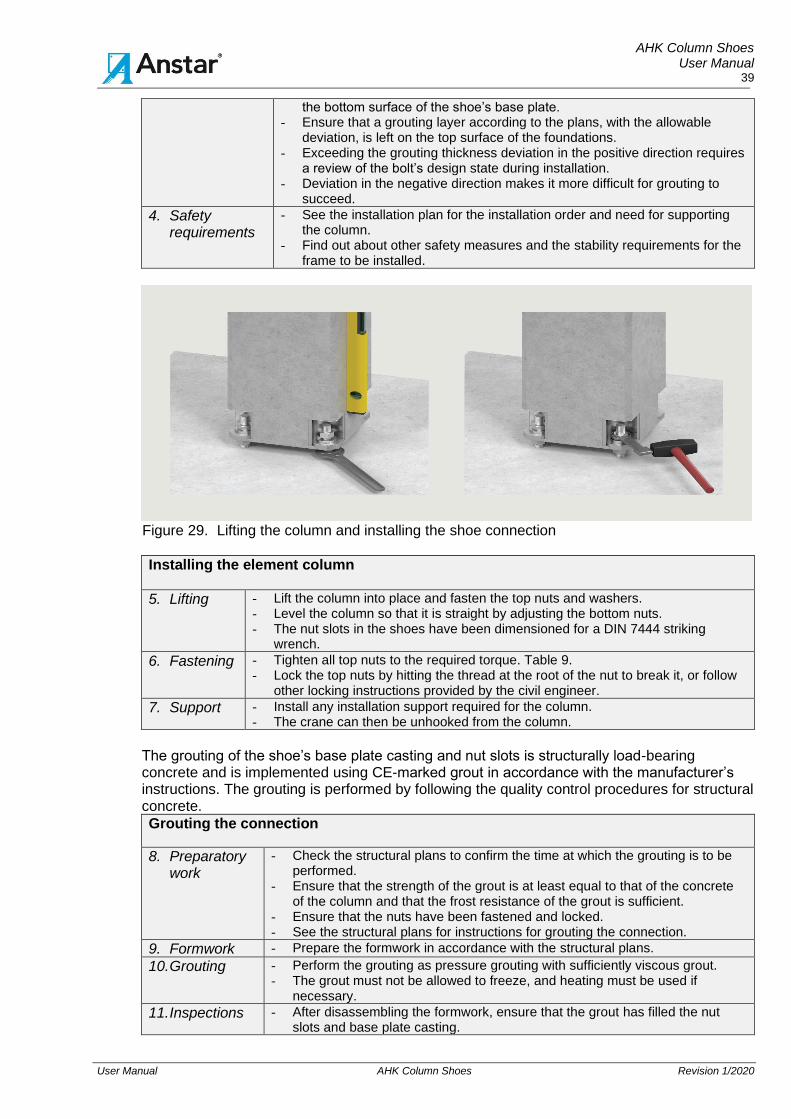
AHK Column Shoes User Manual
39
User Manual AHK Column Shoes Revision 1/2020
the bottom surface of the shoe’s base plate. - Ensure that a grouting layer according to the plans, with the allowable
deviation, is left on the top surface of the foundations. - Exceeding the grouting thickness deviation in the positive direction requires
a review of the bolt’s design state during installation. - Deviation in the negative direction makes it more difficult for grouting to
succeed.
4. Safety requirements
- See the installation plan for the installation order and need for supporting the column.
- Find out about other safety measures and the stability requirements for the frame to be installed.
Figure 29. Lifting the column and installing the shoe connection
Installing the element column
5. Lifting - Lift the column into place and fasten the top nuts and washers. - Level the column so that it is straight by adjusting the bottom nuts. - The nut slots in the shoes have been dimensioned for a DIN 7444 striking
wrench.
6. Fastening - Tighten all top nuts to the required torque. Table 9. - Lock the top nuts by hitting the thread at the root of the nut to break it, or follow
other locking instructions provided by the civil engineer.
7. Support - Install any installation support required for the column. - The crane can then be unhooked from the column.
The grouting of the shoe’s base plate casting and nut slots is structurally load-bearing concrete and is implemented using CE-marked grout in accordance with the manufacturer’s instructions. The grouting is performed by following the quality control procedures for structural concrete.
Grouting the connection
8. Preparatory work
- Check the structural plans to confirm the time at which the grouting is to be performed.
- Ensure that the strength of the grout is at least equal to that of the concrete of the column and that the frost resistance of the grout is sufficient.
- Ensure that the nuts have been fastened and locked. - See the structural plans for instructions for grouting the connection.
9. Formwork - Prepare the formwork in accordance with the structural plans.
10. Grouting - Perform the grouting as pressure grouting with sufficiently viscous grout. - The grout must not be allowed to freeze, and heating must be used if
necessary.
11. Inspections - After disassembling the formwork, ensure that the grout has filled the nut slots and base plate casting.

AHK Column Shoes User Manual
40
User Manual AHK Column Shoes Revision 1/2020
Figure 30. Grouting the shoe connection, principle drawing
Fire protection of the connection
12. Methods - See the structural plans for the planned fire protection methods for shoe connections.
13. Protecting the shoe
- A grouted collar constitutes fire protection of the base plate. - Placing the shoe base plate level with the floor casting suffices as fire
protection. - In other cases, follow the instructions in the structural plans.
14. Grouting cross section
- The base plate casting is usually located inside structural casts, so it is sufficient for the bolts’ fire protection.
7.4 Installation tolerances for the shoe connection
The installation tolerances for the frame are in accordance with EN 13670. The final location of the column is determined on the basis of the manufacturing tolerances of the column’s shoe group and the installation tolerances of the anchor bolts. The location of the column can only be influenced with the play in the shoe’s bolt hole. The play of the hole in the AHK shoe’s base plate is 9–15 mm. Within the limits allowed by these tolerances, the location of the column can be adjusted during the installation using the play of the hole. The column is set in relation to the column lines with the tolerances specified in Table 10.
Table 10. Allowable deviations for the column and connection
1 Column’s centre line location in relation to the module line
deviation ± 5 mm
2 Mutual displacement between two adjacent columns deviation ± 10 mm
3 Allowable deviation of the elevation of the column’s bottom end
deviation ± 10 mm
4 Deviation of the grouting thickness of the column’s base plate
deviation ± 10 mm
5 Deviation of the bolt’s tightening torque from the value in Table 9 or from value Mr,1 as specified in the structural plans.
deviation ± 30%

AHK Column Shoes User Manual
41
User Manual AHK Column Shoes Revision 1/2020
7.5 Corrective measures allowed for the shoe connection on the site The structures of the shoe connection must not be modified without the civil enginer’s and/or shoe manufacturer’s permission. Non-conformity reports must be prepared for any modifications. The following changes in the load-bearing structure of the shoe are allowed on the site. The changes must be documented in the project’s quality documentation.
1. Allowable corrective measure
- If necessary, the shoe’s protective housing for casting can be complemented by spot welding additional plates to the current housing.
- If the washer touches the shoe housing or steel column profile, some material can be removed from that part of the washer such that the washer sits suitably tightly against the top surface of the base plate. The washer must not be left in a slanted position.
- When a bolt is installed in a slanted position, the nut must not be left in a slanted position such that it touches the washer on one side only.
- For such cases, an oblique washer is made that can be installed between the nut and a standard washer to provide the nut with an even contact surface against the washer.
- Standard washers may be added to the connection, provided that the bolt manufacturer’s washer is kept lowermost on the surface of the base plate.
The following corrective measures are not allowed. Changes require a separate non-conformity plan and the civil engineers, and bolt or shoe manufacturer’s approval.
2. Non-allowable corrective measure
- The load-bearing structure of the shoe must not be modified by cutting or welding.
- Reaming the hole in the shoe’s base plate requires a separate non-conformity plan and the shoe manufacturer’s approval.
- The bolt’s threaded section must not be bent or heated.
- No other force transfer structures may be welded to the bolt.
- The bolt and its bonds must not be cut and welded to a new location.
- The bolt must not be welded to the base plate of a shoe or steel column. - The bolt’s washer must be supplied by the bolt manufacturer. The washers
must not be replaced.
- The nut may never install without the bolt’s own washer.
- If the hole in the column’s base plate has been reamed, the washer must be replaced with a larger one.
- The nut of a hot-dip galvanised bolt must not be replaced with a nut based on another standard.
- When the nut has been tightened into place, at least two pitches of the bolt’s thread must be visible. If the thread dimension is lower than this, a non-conformity report must be prepared, and corrective measures approved by the civil engineer.

AHK Column Shoes User Manual
42
User Manual AHK Column Shoes Revision 1/2020
8 SAFETY MEASURES
8.1 Information for preparing work safety instructions for the site
Appointed by the developer, the project’s work safety coordinator is responsible for ensuring work safety during the building work. When preparing work safety instructions for the project, the following must be taken into account in shoe connection installations:
1. Installation - Columns are installed by following the working order in the contractor’s installation plan and the requirement for frame stability during erection determined by the civil engineer.
- The falling of the column and incorrect loading of the bolt connection during installation must be prevented by the following measures:
- The column is lifted using lifting lugs/equipment. - The column must not be moved or lifted from the shoe bolt hole.
- During lifting, the shoe base plate must not hit/rest on the ground or another fixed structure.
- The lifting equipment is unhooked from the column when the column is in place, fastened to all anchor bolts and provided with installation support in accordance with the plans.
- The bolts must not be loaded in ways and with forces deviating from the plan.
2. Stability - The column must never be unhooked from the crane without fastening it to the bolts with all nuts.
- The frame stability under exceptional natural forces must be ensured at the end of the shift.
- The overall stability of a partially installed frame must always be ensured.
3. Structure
- The time at which the shoe connection is to be grouted must be specified in the installation plan.
- Installation of the upper frame must not be continued before the grout has hardened.
- The grouting concrete is part of the load-bearing structure of the connection, so the materials and work methods must be selected such that the grout cannot freeze.
- Any installation supports used for the column are removed in accordance with the installation plan, at the earliest after the grout in the connection has hardened.
8.2 Commissioning a shoe connection during construction
The shoe connection is separately designed for erection state forces and ultimate limit state forces for the frame. There are highly significant differences between these two states in how the connection works. The column connection will only reach the ultimate limit state resistance when the grouting concrete of the nut slots and the column base has reached the design strength. Until then, the column connection and its resistance must only be reviewed using the erection state resistance values. The time at which grouting is to be performed is specified in the installation plan. The grouting must not be postponed, and the column commissioning permit required for continuing with the installation of the upper frame and for additional loading of the column is determined by means of a review.

AHK Column Shoes User Manual
43
User Manual AHK Column Shoes Revision 1/2020
9 INSTALLATION QUALITY CONTROL
9.1 Instructions for monitoring column installations Installation quality control for column connections is carried out in accordance with the quality control plan prepared for the project and site. The structural and dimensional inspections specified in the implementation breakdown are performed on the element frame. The instructions to be followed for the requirements for concrete structures are provided in EN 13670 [17] and EN 13325 [18]. An inspection report is prepared for the element frame’s quality control and dimensional inspections and saved in the project’s quality documentation. The inspection measures to be observed for shoe connections are:
1. Before column installation
- Ensure that the bolts are not damaged. - Following the installation plan regarding the installation order of the
elements. - Need for supporting the columns during installation. - Checking the elevation of the bottom ends of the columns and the bolts.
2. After column installation, before grouting
- Check that the column connection has been installed at the elevation specified in the plans.
- Ensure that the correct washers have been used and the nuts have been tightened to the torque specified.
- Ensure that at least two pitches of the bolt’s thread are visible from the nut.
- Ensure that the strength of the grouting concrete is in accordance with the
plans.
3. After grouting the connection
- Check that the nut holes and joint grouting have been made appropriately and with the concrete strength according to the plans.
- Ensure that all the nut holes and the grouting joint have been filled with concrete.
- Ensure that the grouting of the connection meets the fire protection requirements for the connection.
4. Deviations If the frame installer deviates from the approved plans and documents in any of the following tasks: - quality control - performing the installation work, lifting and transfers - installation materials - structure tolerances and dimensional inspection of the frame - required inspections and their documentation, the installer is obliged to start documenting the non-conformity upon observing the deviation from the plan and to have the client approve the resulting measures. Non-conformity reports are saved in the project’s quality documentation.
9.2 Final documentation of installation quality control
When the job has been accepted, the frame installer is required to deliver the inspection and quality control documentation created during the installation work to the client.
1. Readiness inspection records
- As-built dimension record for the bolt locations. - Commissioning inspection of the columns after the grouting of the
connection.
2. Non-conformity reports
- Any non-conformity reports prepared during the installation of the bolt connection are handed over.
3. Product approval as-built
- CE marking certificates or corresponding product approval information for materials purchased for the site.
- As-built documentation for changes made to the structure.

AHK Column Shoes User Manual
44
User Manual AHK Column Shoes Revision 1/2020
REFERENCES [1] EN 1090-1 Execution of steel structures and aluminium structures. Part 1: For conformity assessment.
[2] EN 1090-2:2018 Execution of steel structures and aluminium structures. Part 2: Technical requirements for steel structures.
[3] EN ISO 3834 Quality requirements for fusion welding of metallic materials. Part 1: Criteria for the selection of the appropriate level of quality requirements, and parts 2–5
[4] EN 1990, Eurocode. Basis of structural design
[5] EN 1991-1, Eurocode 1. Actions on structures, parts 1–7
[6] EN 1992-1-1, Eurocode 2. Design of concrete structures. Part 1-1: General rules and rules for buildings.
[7] EN 1992-1-2, Eurocode 2. Design of concrete structures. Part 1-2: General rules. Structural fire design.
[8] EN 1993-1, Eurocode 3. Design of steel structures. Part 1-1: General rules and rules for buildings. Parts 1–10:
[9] CEN/TS 1992-4-1 Design of fasteners in concrete – Part 4-1: General (Cancelled)
[10] CEN/TS 1992-4-2 Design of fasteners use in concrete – Part 4-2: Headed Fasteners (Cancelled)
[11] EN ISO 5817, Welding. Fusion-welded joints in steel, nickel, titanium and their alloys. Weld classes.
[12] EN ISO 12944, Paints and varnishes. Corrosion protection of steel structures by protective paint systems. Part 1 and parts 2–7.
[13] EN ISO 1461, Hot dip galvanized coatings on fabricated iron and steel articles. Specifications and test methods.
[14] EN 10025, Hot rolled products of structural steels. Part 1: General technical delivery conditions.
[15] EN ISO 1684 Fasteners. Hot dip galvanized coating
[16] EN 17760-1 Welding. Welding of reinforcing steel. Part 1: Load-bearing welded joints.
[17] EN 13670 Execution of concrete structures
[18] EN 13325 Precast concrete products. Column and beam elements.
[19] EN 13369 Common rules for precast concrete products.
[20] Removed
[21] Anstar Oy. AHK Column Shoes user manual
[22] Anstar Oy. Rebar Bolts user manual
[23] Removed
[24] EN 1992-4:2018, Design of concrete structures. Part 4. Design of fastenings for use in concrete.
LIST OF TABLES Table 1. AHK shoe dimensions .......................................................................................................................................................................... 6 Table 2. AHK-K shoe dimensions ...................................................................................................................................................................... 7 Table 3. Shoe manufacturing programme and user manuals .......................................................................................................................... 8 Table 4. Design value of AHK shoe’s axial force resistance. ............................................................................................................................ 9 Table 5. Minimum columns for AHK and AHK-K shoes ................................................................................................................................. 11 Table 6. Rebar bolts suitable for AHK and AHK-K shoes in various connection types ................................................................................. 22 Table 7. Supplementary reinforcement for shoes with the shoe design values ............................................................................................. 30 Table 8. Required nominal value Cnom for the concrete cover and placement and surface treatment recommendations for the shoe ....... 34 Table 9. Bolt elevation, grouting thickness and torque for AHK and AHK-K shoes ....................................................................................... 38 Table 10. Allowable deviations for the column and connection ........................................................................................................................ 40
PICTURES Figure 1. Typical application of an AHK shoe ..................................................................................................................................................... 4 Figure 2. AHK shoes in rectangular column connections in office, commercial buildings ................................................................................ 4 Figure 3. AHK-K shoes in round column connections in commercial and office buildings ............................................................................... 5 Figure 4. AHK and AHK-K shoes in asymmetrical rectangular column connections ........................................................................................ 5 Figure 5. AHK shoe structure .............................................................................................................................................................................. 6 Figure 6. AHK-K shoe structure .......................................................................................................................................................................... 7 Figure 7. Column connection’s grouting and minimum concrete strengths .................................................................................................... 11 Figure 8. Main window with the AHK and AHK-K shoe connection ................................................................................................................ 15 Figure 9. ACOLUMN software connection types ............................................................................................................................................. 17 Figure 10. Tab 2. Material strengths, concrete cracking state and reinforcement. ........................................................................................... 18 Figure 11. Tab 3. Dimension of upper column ................................................................................................................................................... 18 Figure 12. Tab 4. Selecting the base dimensions .............................................................................................................................................. 19 Figure 13. Tab 5. Selecting the fire resistance method for the column connection.......................................................................................... 19 Figure 14. Tab 6. Size of supplementary reinforcement .................................................................................................................................... 20 Figure 15. Forces on the connection during the erection state and ultimate limit state .................................................................................... 21 Figure 16. Windows for placing the shoes, bolts and column’s main pieces of rebar ....................................................................................... 21 Figure 17. Erection state. Axial and shear force resistance of bolt. ................................................................................................................... 27 Figure 18. Ultimate limit state. Axial forces resistance and utilisation rate of shoe. .......................................................................................... 27 Figure 19. Ultimate limit state. Axial and shear force resistances of shoe......................................................................................................... 28 Figure 20. Ultimate limit state. Utilisation degree of shoe tie bars. .................................................................................................................... 28 Figure 21. Ultimate limit state. Utilization degree of tie bars. Shoe and column................................................................................................ 29 Figure 21. Supplementary reinforcement for AHK and AHK-K shoes. .............................................................................................................. 30 Figure 23. Supplementary reinforcement calculated for the shoe connection. ................................................................................................. 31 Figure 24. Ultimate limit state. Resistance graph and loading points, main axis direction. ............................................................................... 32 Figure 25. Ultimate limit state. Stress/deformation of the grouting cross-section. ............................................................................................. 32 Figure 26. Ultimate Limit State. 3D stress state of the grouting cross-section .................................................................................................. 33 Figure 27. Stress/deformation graph of the column and grouting concrete ...................................................................................................... 33 Figure 28. Methods for protecting the nut slots of shoes during casting............................................................................................................ 36 Figure 29. Lifting the column and installing the shoe connection....................................................................................................................... 39 Figure 30. Grouting the shoe connection, principle drawing .............................................................................................................................. 40

AHK Column Shoes User Manual
45
User Manual AHK Column Shoes Revision 1/2020