ah-m1 handheld pulse oximeter user's manual- · pdf filechapter 3 basic operations ......
TRANSCRIPT

Handheld Pulse OximeterModel: AH-M1
Instruction Manual
Issued Date: Jul. 12, 2011Ver.1.0

Handheld pulse oximeter instruction manual
Product Information
Product Model: AH-M1
Product Name: Handheld pulse oximeter
Manufacturer: Acare Technology Co., Ltd.
After Service Contact Information:
Address: 6F.-6, No.5, Wuquan 1st Rd., Xinzhuang Dist.,
New Taipei City 242, Taiwan
TEL : +886-2-2298-8170
FAX : +886-2-2298-8560
Email: [email protected]
Revision History
This manual has a revision number. This revision number
changes whenever the manual is updated due to software or
technical specification change. Contents of this manual are
subject to change without prior notice.
Document No.: P2000040-1
Revision number: 1.0
Release time: 2011-07
Copyright © 2011 Acare Technology Co., Ltd. All rights
reserved.
I

Handheld pulse oximeter instruction manual
CE mark
EC Representative Name:
MEDIPRO
Villapark Business Park, Av Quitapesares 8, Building 8,
Villaviciosa de Odon (Madrid) 28670, Spain
Statement
The manufacturer, Acare, holds the copyright to this
manual, and is entitled to treat it as a proprietary file. This
manual is only to be used for supporting the operation,
maintenance and service of the AH-M1 product, and it
cannot be resold or republished by any other party.
This manual contains exclusive information protected by
copyright laws and we, Acare, reserve its copyright. No parts
of this manual shall be photocopied, Xeroxed or translated
into other languages without written approval from the
manufacturer.
The contents of this manual are subject to amendment
without notification.
II

Handheld pulse oximeter instruction manual
Manufacturer's ResponsibilityThe manufacturer will be responsible for the safety,
reliability and performance of the instrument under the
following circumstances only:
All installation, expansion, readjustment, renovation or
repairs of the instrument are conducted by personnel
certified by the manufacturer.
The storage conditions, operating conditions and
electrical status of the instrument conform to the
product specification.
The instrument is used in accordance with the user
manual.
About this manual
This manual contains the instructions necessary to
operate the product safely and in accordance with its
function and intended use. Observance of this manual is a
prerequisite for proper product performance and correct
operation of the product, and ensures patient and operator
safety.
III

Handheld pulse oximeter instruction manual
This manual is based on the maximum potential
configuration of the product, and therefore some contents
may not apply to your device. If you have any questions,
please contact us.
This manual is an integral part of the product. It should
always be kept close to the equipment so that it can be
referred to when needed.
All illustrations in this manual serve only as examples.
They may not necessarily reflect the setup or data displayed
on your product.
Key:
Bold Italic text is used in this manual to quote the
referenced chapter or sections.
【】 is used to signify text as it appears on the
product screen.
→ is used to indicate operational procedures.
IV

Handheld pulse oximeter instruction manual
Warning: Indicates a potential hazard or unsafe
practice that, if not avoided, will result in death
or serious injury.
Caution: Indicates a potential hazard or unsafe
practice that, if not avoided, could result in minor
personal injury or product/property damage.
Note: Provides application tips or other useful
information to ensure that you get the most from
your product.
V

ContentsChapter 1 General Introduction........................................1
1.1 Intended Use...............................................................1
1.2 Main Unit...................................................................2 1.2.1 Front View............................................................2 1.2.2 Rear View.............................................................5 1.2.3 Side View..............................................................6
1.3 Display Views.............................................................7 1.3.1 Large Numeric Display Mode...............................7 1.3.2 SpO2 Waveform Display Mode............................9
Chapter 2 Safety.................................................................1
2.1 Safety Information......................................................1
2.2 Explanation of Symbols..............................................3
Chapter 3 Basic Operations...............................................1
3.1 Unpacking and Checking............................................1
3.2 Getting Started............................................................2
3.3 Starting the oximeter...................................................3
3.4 General Setup.............................................................3 3.4.1 Beep Volume Setup...............................................3 3.4.2 Key Volume Setup................................................4 3.4.3 Adjust the Screen Brightness................................4 3.4.4 Scan Speed Setup..................................................4
3.5 Date and Time Setup...................................................5

3.6 Selecting the Work Mode............................................5 3.6.1 Continuous Monitoring Mode...............................6 3.6.2 Spot-checking Mode.............................................7
3.7 Selecting Patient Type.................................................8
3.8 Entering/Exiting the Demo Mode...............................8
3.9 Changing the Language..............................................9
3.10 Checking the Version ...............................................9
3.11 Restoring the Factory Configuration.........................9
3.12 Shutting off the Oximeter.......................................10
Chapter 4 Alarm.................................................................1
4.1 Alarm Categories........................................................1
4.2 Alarm Levels..............................................................2
4.3 Alarm Indicators.........................................................3 4.3.1 Alarm tone............................................................4 4.3.2 Alarm Lamp .........................................................5 4.3.3 Alarm Message.....................................................6 4.3.4 Flashing Numeric..................................................6
4.4 Alarm Status Symbol..................................................6
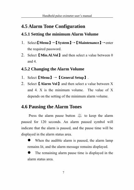
4.5 Alarm Tone Configuration..........................................7 4.5.1 Setting the minimum Alarm Volume.....................7 4.5.2 Changing the Alarm Volume.................................7
4.6 Pausing the Alarm Tones.............................................7
4.7 Shutting off the Alarm Volume...................................8
4.8 When an Alarm Occurs...............................................9
Chapter 5 Measuring SpO2................................................1
5.1 Introduction................................................................1
5.2 Safety Information......................................................2
5.3 Monitoring Procedure.................................................4
5.4 SpO2 Display..............................................................5
5.5 PR Display..................................................................5
5.6 SpO2 Alarm Setup......................................................6 5.6.1 Switching SpO2 Alarm On/Off.............................6 5.6.2 Setting the Alarm Level........................................6 5.6.3 Adjusting the Alarm Limit....................................6 5.6.4 Altering the Desaturation Limit.............................7
5.7 PR Alarm Setup..........................................................7 5.7.1 Switching PR Alarm On/Off.................................7 5.7.2 Setting the Alarm Level........................................7 5.7.3 Adjusting the Alarm Limit....................................8
Chapter 6 Reviewing...........................................................1
6.1 Introduction................................................................1
6.2 Reviewing Screen.......................................................1
6.3 Reviewing Setup.........................................................2
Chapter 7 Battery...............................................................1
7.1 Introduction................................................................1
7.2 Installing Batteries......................................................3
7.2.1 Opening the Battery Door.....................................3 7.2.2 Installing the Alkaline Battery...............................4 7.2.3 Installing the Lithium-Ion Battery.........................5
7.3 Charging Lithium Ion Battery.....................................6
7.4 Optimizing Battery Performance................................7
7.5 Checking the Lithium-Ion Battery..............................8
7.6 Disposing of the Batteries...........................................9
Chapter 8 Maintenance and Cleaning...............................1
8.1 Introduction................................................................1
8.2 Annual Safety Checks.................................................2
8.3 Cleaning the Oximeter................................................4
8.4 Cleaning SpO2 Sensor................................................5
8.5 Disposal......................................................................6
Chapter 9 Accessories.........................................................1
Appendix A Product Specifications...................................1
A.1 Safety Specifications..................................................1
A.2 Physical Specifications...............................................1
A.3 Environmental Specifications.....................................2
A.4 Charging Specifications.............................................2 A.4.1 AC-DC Adapter (Optional)...................................2 A.4.2 Battery Specification............................................2
A.5 Hardware Specifications............................................4

A.5.1 Display.................................................................4 A.5.2 Indicating LED.....................................................4 A.5.3 Audio Indicating...................................................5 A.5.4 Buttons.................................................................5 A.5.5 Sensors.................................................................6
A.6 Data Storage...............................................................6
A.7 Measurement Specifications.......................................7 A.7.1 Digital SpO2........................................................7 A.7.2 Nellcor SpO2 .......................................................8 A.7.3 Alarm limit specifications....................................8
Appendix B EMC.............................................................10
Appendix C Factory Defaults..........................................15
C.1 Alarm Setup.............................................................15
C.2 System Setup............................................................15
C.3 SpO2 Setup..............................................................16
C.4 Trend Setup..............................................................16
Appendix D Alarm Message............................................17
D.1 Physiological alarm..................................................17
D.2 Technical alarm........................................................18
Chapter 1 General Introduction
1.1 Intended Use
The AH-M1 handheld pulse oximeter is intended for
continuously monitoring or spot checking peripheral oxygen
saturation (SpO2) and pulse rate (PR) for adult, pediatric or
neonatal patients.
This device can be used in institutions or units with
health care capability. This includes outpatient departments,
emergency rooms and departments of internal medicine in
hospitals, ordinary departments in clinics, nursing hospitals
and community medical institutions. It may also be used in
the home.
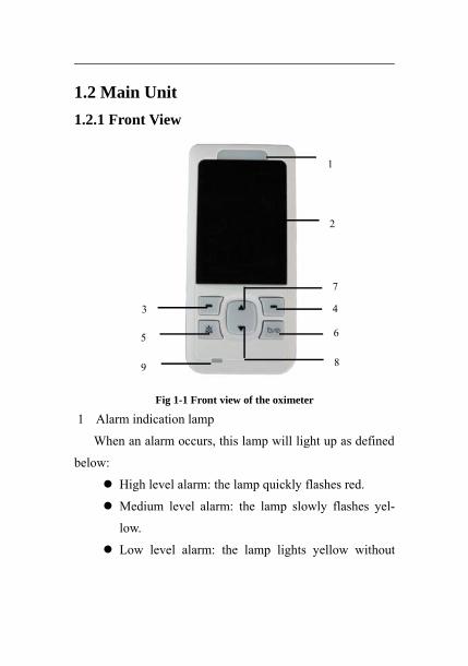
1.2 Main Unit1.2.1 Front View
Fig 1-1 Front view of the oximeter
1 Alarm indication lamp
When an alarm occurs, this lamp will light up as defined
below:
High level alarm: the lamp quickly flashes red.
Medium level alarm: the lamp slowly flashes yel-
low.
Low level alarm: the lamp lights yellow without
6
4
5
3
9
1
2
7
8

flashing.
2 Display screen
3 Left button
Press this button to:
Enter the main menu under the monitoring screen.
Select the highlighted menu item under the menu
screen.
4 Right button
Press this button to:
Switch the screen display between large numeric
mode and SpO2 waveform mode under the
monitoring screen.
Exit current menu under the menu screen.
5 Alarm pause button
Pressing this button:
Will not work when the alarm volume is off.
Can pause the alarm for 120 seconds when the
alarm volume is on.
Changes the alarm message to prompt message
when “Sensor off” alarm is activated.
Note: the alarm can-not be permanently switched

off.
6 Power button
After the batteries are installed:Press this button to turn on the oximeter.Press and hold it for 2 seconds to turn the oximeter off.
7 Up button
Press this button to:
Raise the volume of the heart beat displayed
Move the cursor upwards or increase the value of a
selected menu item under the menu screen.
8 Down button
Press this button to:
Lower the volume of the heart beat displayed
Move the cursor downwards or decrease the value
of a selected menu item.
9 Battery charging indicating lamp
Lights orange when the battery is being charged.
Will show no light when the battery is fully charged
or not being charged.

1.2.2 Rear View
Fig 1-2 Rear view of the oximeter
1. Speaker
2. Battery door
1
2

1.2.3 Side View
Topside: Downside: Leftside:
Fig 1-3 Side view of the oximeter
1. SpO2 probe connector
2. Cord hold
3. Power supply connector
Used to connect the charger stand.
4. Infrared port
A port through which a personal computer can
communicate with the product, to export data in real
time.
1
3
42
1.3 Display Views
This device features an automatic display rotation
(gravity activated), which allows vertical and horizontal
positioning of the screen, to maximize space utilization and
visibility.
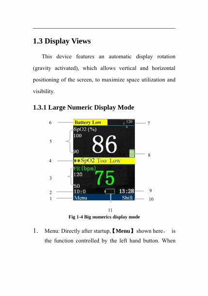
1.3.1 Large Numeric Display Mode
Fig 1-4 Big numerics display mode
1. Menu: Directly after startup, 【Menu】 shown here, is
the function controlled by the left hand button. When
1
3
4
5
6
10
11
92
8
120s
7

appropriate, press the left button to enter 【Menu】.
2. Patient ID No.: When 【Continuous】 is selected for
work mode, the patient ID is set at 0 at all times; when
【 Spot-Check 】 is selected, the ID will display a
number between 1 and 99.
3. PR parameter area: Current pulse rate (PR) value and its
high and low alarm limits are displayed in this area.
4. Physiological alarm area: Current physiological alarm
information is displayed in this area.
5. SpO2 parameter area: Current SpO2 value and its high
and low alarm limits are displayed in this area.
6. Technical alarm and prompt information area: Current
technical alarm and prompt information is shown in this
area.
7. Alarm status area: Alarm status symbols and alarm
pause time are displayed in this area.
8. Pleth bar: Pulse intensity is indicated by the number of
stacked blocks visible.
9. System time: Current time is shown in the area.
10. Shift: Directly after startup, 【Shift】shown here is the
function controlled by the right hand button. Press the
right hand button to shift between different display

modes.
11. Battery symbol: This symbol indicates the remaining
quantity of electrical charge in the batteries.
1.3.2 SpO2 Waveform Display Mode
Fig 1-5 SpO2 waveform display mode
1. SpO2 waveform area: The waveform shown in this area
illustrates the current SpO2 volume curve of the patient
being monitored.
2. SpO2 parameter area: Current SpO2 value and its upper
and lower alarm limits are displayed in this area.
3. PR parameter area: Current PR value and its upper and
lower alarm limits are displayed in this area.
2
1
3

Handheld pulse oximeter user’s manual
Chapter 2 Safety
2.1 Safety Information
Warning:
Explosion hazard: Do not use the oximeter in the
presence of flammable anesthetics mixed with air,
oxygen, or hydrogen.
Do not use the product in the presence of high
power appliances such as high voltage cables, X-ray
machines, ultrasound equipment or a defibrillator.
Keep the oximeter away from dust, vibration,
corrosive substances, explosive materials, high
temperature and moisture.
The device is not designed for use in a sterile field
The oximeter should be handled with care so as to
avoid it getting knocked or falling.
1

Handheld pulse oximeter user’s manual
Warning:
Do not use this device during defibrillation.
When the device is in use, ensure that the batteries
have sufficient charge remaining; otherwise start-
up abnormalities may occur or the measurement
data may be inaccurate.
Patients must not wear nail varnish while using the
pulse oximeter as this will lead to unreliable SpO2
measurements.
Measurements and pulse signals can be affected by
certain environmental conditions, errors in
applying the sensor, and certain patient conditions.
See the appropriate sections of this manual for
specific safety information.
The use of accessories, sensors, and cables other
than those specified may result in increased
emission, low anti-disturbance and/or may lead to
the oximeter producing invalid readings. It is
advisable to check the oximeter at least once a
month.
2
Handheld pulse oximeter user’s manual
Caution: In order to obtain accurate results, the
oximeter should be used in a quiet and comfortable
environment.
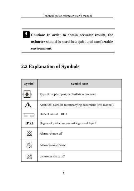
2.2 Explanation of Symbols
Symbol Symbol Note
Type BF applied part, defibrillation protected
Attention: Consult accompanying documents (this manual).
Direct Current(DC)
IPX1 Degree of protection against ingress of liquid
Alarm volume off
Alarm volume pause
parameter alarm off
3

Handheld pulse oximeter user’s manual
Symbol Symbol Note
Beep volume off
Power supply connector
Left/right button
Up button
Down button
Date of manufacture
Manufacturer
CE mark
SN Serial number
Power button
Symbol for the marking of electrical and electronics devices according to Directive 2002/96/EC.
4

Handheld pulse oximeter user’s manual
Chapter 3 Basic Operations
3.1 Unpacking and Checking
Open the package. Take out the oximeter and its accessories. The following parts are provided in the package:
Parts Standard Optional Quantity
SpO2 probes
(DB9 plugs)√ 1
User’s manual √ this manual
Lithium battery √ 1
AC-DC adapter √ 1
Battery charger stand √ 1
Protective cover √ 1
Clip with lanyard √ 1
QuickStart √ 1
CDROM √ 1
Check list √ 1
Alkaline battery √ 3
1
Handheld pulse oximeter user’s manual
3.2 Getting Started
1. Before using the oximeter to take measurements for the
first time, carry out the following checks on the oximeter
and all connected modules:
——Check for any mechanical damage;
— — Check for correct connection between of all the
external cables and accessories.
2. Insert batteries into the battery compartment. Make sure
that the battery has sufficient power. When using
rechargeable batteries for the first time, you must charge
them,first, following the instructions given in the Battery
chapter.
Warning:
If the oximeter is mechanically damaged, or if it is
not working properly, do not use it on a patient for
any monitoring procedure. Contact your service
personnel.
To avoid the risk of explosions, do not use the oximeter in the presence of flammable anesthetics, vapors or liquids.
2

Handheld pulse oximeter user’s manual
3.3 Starting the oximeter
Press the button to turn on the oximeter. The alarm indication lamp should flash, and then stop. The system should give a beep and enter the main screen. After starting the oximeter you can change the settings for more convenient use, as shown in section 3.4.
3.4 General Setup
Press the Left button to enter 【 Menu 】 , then select【General Setup】 to enter the general setup menu shown as follows. You can set parameters for the following functions: .
Fig 3-1 General setup window
3.4.1 Beep Volume SetupPress the Left button to select the item, then adjust its
value using the Up or Down button. You can select from 0 to 4. A sign will be shown at the bottom of the monitoring
3
Handheld pulse oximeter user’s manual
screen when the beep volume is off.
3.4.2 Key Volume Setup
Press the Left button to select the item, then adjust the
value using the Up or Down button. You can select from 0 to
4.
3.4.3 Adjust the Screen BrightnessPress the Left button to select the item, then adjust the
value using the Up or Down button. You can select from 1 to 5. Selecting the minimum brightness can save power.
Caution: If the oximeter is used outdoors, or if the
ambient light is strong, set the screen brightness
to a higher level.
3.4.4 Scan Speed Setup
Press the Left button to select the item, then adjust its
value using the Up or Down button. You can select from
12.5mm/s to 25mm/s.
4
Handheld pulse oximeter user’s manual
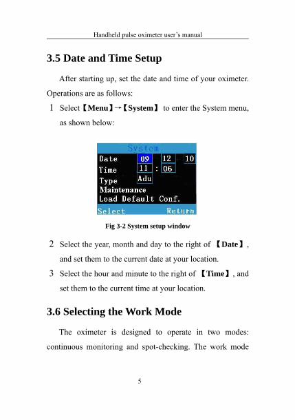
3.5 Date and Time Setup
After starting up, set the date and time of your oximeter.
Operations are as follows:
1 Select 【Menu】→【System】 to enter the System menu,
as shown below:
Fig 3-2 System setup window
2 Select the year, month and day to the right of 【Date】,
and set them to the current date at your location.
3 Select the hour and minute to the right of 【Time】, and
set them to the current time at your location.
3.6 Selecting the Work Mode
The oximeter is designed to operate in two modes:
continuous monitoring and spot-checking. The work mode
5

Handheld pulse oximeter user’s manual
that is currently selected will be displayed in the technical
alarm area. You can choose the oximeter’s work mode
through the following steps:
1. Select【System】→【Maintenance】,at which point a
window will pop up and ask for your password. Input
the password and select【OK】to enter the maintenance
window shown as follows:
Fig 3-3 Maintenance window
2. Select【Work Mode】, and then set the oximeter’s work
mode to【Continuous】or【Spot-Check】.
3.6.1 Continuous Monitoring Mode
The continuous monitoring mode is intended for long-
term monitoring of a patient. This mode is normally selected
when the patient is in hospital or under transport., The
6

Handheld pulse oximeter user’s manual
default patient ID given by the system is 0. When the
oximeter’s memory reaches full capacity, the oldest stored
data will be deleted.
3.6.2 Spot-checking Mode
Spot-checking mode is intended for short-term, on-site
measurement. This mode is normally selected to check up on
the condition of a patient by doctors making rounds of a
ward. The patient ID will automatically increase from 1 to 99
with each patient. Details are as follows:
Apply the SpO2 sensor to the patient. After valid SpO2
signals are detected,
1. The patient ID flashes and after 8 seconds will automat-
ically increase by 1 number to admit a new patient.
2. Pressing the Left hand button when the current patient
ID is flashing, will make the patient ID stop flashing and
the ID number will remain unchanged. The new patient
will not be admitted and further measurements will be
stored under the current patient ID.
3. When the storage of patient measuring data reaches its
limit, the patient ID will be reset to 1 and new data will
7
Handheld pulse oximeter user’s manual
replace the information stored under the first patient ID.
3.7 Selecting Patient Type
To select the patient type,1. Select【Menu】→【System】→【Type】.2. Set【Type】to【Adu】, Adult【Ped】Pediatric
or 【Neo】Neonate.
3.8 Entering/Exiting the Demo Mode
To enter the demo mode:1. Select 【Menu】→【System】→【Maintenance】→
enter the required password.2. Set【Screen】to【Demo】and the message【Demo
Mode】will appear in the technical alarm area. To exit the demo mode:1. Select 【Menu】→【System】→【Maintenance】→
enter the required password.2. Set【Screen】to【Normal】.
Caution: The Demo mode is for demonstration
purpose only. Do not enter the Demo Mode when
a patient is being monitored, to avoid mistaking
simulated data for the patient’s actual data. This
8

Handheld pulse oximeter user’s manual
could result in improper patient monitoring and
delayed treatment.
3.9 Changing the Language
Select 【Menu】→【System】→【Maintenance】, enter the
required password. Select 【 Factory Setup 】 to set
【Language 】.
3.10 Checking the Version
Select 【Menu】→【System】→【Maintenance】, enter the
required password. Select【Factory Setup】 to check the
version of the oximeter.
3.11 Restoring the Factory Configuration
If you have made changes to the system’s configuration
and want to restore the original factory settings, follow this
procedure:
1. Select【Menu】→【System】.
2. Select【Load Default Conf.】. A pop up window
will appear, asking you to confirm that you want
9

Handheld pulse oximeter user’s manual
to return to the original configuration.,
Select【OK】to restore the factory configuration.
3.12 Shutting off the Oximeter
To turn off the oximeter, follow the steps below:
1. Confirm that patient monitoring is complete.
2. Disconnect the SpO2 sensors form the oximeter.
3. Press the power button and hold it for 2 seconds to
turn off the oximeter.
Caution: Under the Spot-check mode, if the oximeter is not in use and there has been no button operation for more than 5 minutes, the oximeter will shut down automatically.
10

Handheld pulse oximeter user’s manual
Chapter 4 Alarm
’Alarm’ refers to a prompt that is given by the oximeter
through visual, audible and other means, to alert medical
personnel when a vital sign appears abnormal or the
oximeter experiences a technical problem.
Note: The oximeter generates all audible and visual
alarms through a speaker, a visual alarm lamp
and the screen.
4.1 Alarm Categories
The oximeter’s alarms fall into three categories:
1.Physiological alarms
Physiological alarms are triggered when a monitored
parameter moves outside of set alarm limits, or by an
abnormal patient condition. Physiological alarm messages
are displayed in the physiological alarm area.
2.Technical alarms
1
Handheld pulse oximeter user’s manual
Technical alarms are triggered by a device malfunction
or a patient data distortion, due to system problems or
improper operation of the oximeter. Technical alarm
messages are displayed in the technical alarm area.
3.Prompt messages
Prompt messages are not alarm messages. The pulse
oximeter will sometimes show messages updating the user
on the system status, separate from the physiological and
technical alarm messages,. Prompt messages are displayed in
the technical alarm area.
4.2 Alarm Levels
1. The oximeter’s physiological alarms fall into three
categories of increasing severity: low level alarms,
medium level alarms, and high level alarms.
High level alarms
Indicate that the patient is in a life-threatening
situation and emergency treatment is required.
Medium level alarms
Indicate that the patient’s vital signs appear abnormal
and immediate treatment is required.
2

Handheld pulse oximeter user’s manual
Low level alarms
Indicate that the patient’s vital signs appear abnormal
and immediate treatment may be required.
2. The oximeter’s technical alarms can be classified into
two categories of severity: medium level alarms and
low level alarms.
Caution: The technical alarms cannot be changed by the user.
4.3 Alarm Indicators
When an alarm occurs, the oximeter will indicate it
through the following signals:
Alarm tone: The speaker on the rear panel of the
oximeter will sound the alarm in different tones,
according to the severity of the alarm.
Alarm lamp: The alarm lamp on the front of the
oximeter will flash a different color and speed,
according to the severity of the alarm.
3

Handheld pulse oximeter user’s manual
Alarm message: Alarm messages are displayed on the
front screen.
Flashing numeric: The monitored parameter that has
been breached to cause the alarm to sound will flash.
Caution: Alarm lamp, alarm tone and alarm
messages will vary according to the level of
severity of the alarm.
4.3.1 Alarm tone
The different level alarms are indicated by the system in
the following audio tones:
Alarm level Audible prompt
High “DO-DO-DO------DO-DO, DO-DO-DO------DO-DO”
Medium “DO-DO-DO”
Low “DO-”
4
Handheld pulse oximeter user’s manual
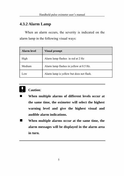
4.3.2 Alarm Lamp
When an alarm occurs, the severity is indicated on the
alarm lamp in the following visual ways:
Alarm level Visual prompt
High Alarm lamp flashes in red at 2 Hz
Medium Alarm lamp flashes in yellow at 0.5 Hz.
Low Alarm lamp is yellow but does not flash.
Caution: When multiple alarms of different levels occur at
the same time, the oximeter will select the highest
warning level and give the highest visual and
audible alarm indications.
When multiple alarms occur at the same time, the
alarm messages will be displayed in the alarm area
in turn.
5

Handheld pulse oximeter user’s manual
4.3.3 Alarm MessageWhen an alarm occurs, the alarm message will be
displayed in the alarm area.
The system uses the following alarm symbols to match
the level of physiological alarm messages:
High level alarms: ***
Medium level alarms: **
Low level alarms: *
The system uses the following background colors to
indicate different messages and match the alarm level:
High level alarms: red
Medium level alarms: yellow
Low level alarms: yellow
4.3.4 Flashing Numeric
When a physiological alarm occurs, the flashing numeric indicates the parameter that has been breached
4.4 Alarm Status Symbol
Indicates that the alarm sound is turned off.
Indicates that the alarm sound is paused.
Indicates that individual measurement alarms are
turned off.
6
Handheld pulse oximeter user’s manual
4.5 Alarm Tone Configuration4.5.1 Setting the minimum Alarm Volume
1. Select【Menu】→【System】→【Maintenance】→enter
the required password.
2. Select【Min.Al.Vol】and then select a value between 0
and 4.
4.5.2 Changing the Alarm Volume
1. Select【Menu】→【General Setup】.
2. Select【Alarm Vol】and then select a value between X
and 4. X is the minimum volume. The value of X
depends on the setting of the minimum alarm volume.
4.6 Pausing the Alarm Tones
Press the alarm pause button to keep the alarm
paused for 120 seconds. An alarm paused symbol will
indicate that the alarm is paused, and the pause time will be
displayed in the alarm status area.
When the audible alarm is paused, the alarm lamp
remains lit, and the alarm message remains displayed.
The remaining alarm pause time is displayed in the
alarm status area.
7
Handheld pulse oximeter user’s manual
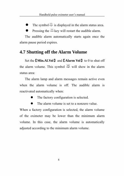
The symbol is displayed in the alarm status area.Pressing the key will restart the audible alarm.
The audible alarm automatically starts again once the
alarm pause period expires.
4.7 Shutting off the Alarm Volume
Set the 【Min.Al.Vol】 and 【Alarm Vol】 to 0 to shut off
the alarm volume. This symbol will show in the alarm
status area:
The alarm lamp and alarm messages remain active even
when the alarm volume is off. The audible alarm is
reactivated automatically when:
The factory configuration is selected.
The alarm volume is set to a nonzero value.
When a factory configuration is selected, the alarm volume
of the oximeter may be lower than the minimum alarm
volume. In this case, the alarm volume is automatically
adjusted according to the minimum alarm volume.
8

Handheld pulse oximeter user’s manual
Warning:
When the alarm sound is switched off, the oximeter
will give no audible alarm tones even if a new
alarm occurs. Any decision to switch off the alarm
sound should be made with extreme caution.
Users should not rely exclusively on the audible
alarm system for patient monitoring. Adjusting the
alarm volume to a low level may result in a hazard
to the patient. Always keep the patient under close
surveillance.
4.8 When an Alarm Occurs
Note: When an alarm occurs, always check the
patient’s condition first.
Check which alarm message has appeared on the screen.
This is necessary to identify the alarm and the appropriate
action to be taken.
1. Check the patient’s condition.
9

Handheld pulse oximeter user’s manual
2. Identify which parameters have set off the alarm, and
identify the alarm category.
3. Identify the cause of the alarm.
4. Silence the alarm, if necessary.
5. When the cause of the alarm has been identified and
addressed, check that the alarm system is working
properly.
Alarm messages for individual parameters can be
found in Appendix D Alarm message.
10

Handheld pulse oximeter user’s manual
Chapter 5 Measuring SpO2
5.1 Introduction
The measurement of oxygen saturation of arterial blood
(also known as peripheral oxygen saturation, usually
shortened to SpO2) relies on the principles of light spectra
and volume tracing. An LED in the oximeter emits light rays
through the body, wherever the probe is used, e.g. through
the finger, at two different specific wavelengths. Each of
these is selectively absorbed by oxygenated hemoglobin and
deoxyhemoglobin in the blood. An optical receptor measures
the changes in the light intensity after the light passes
through the capillary network and estimates the ratio of
oxygenated hemoglobin and the total hemoglobin.
1
SpO2 % = ×100%
oxygenated hemoglobin
oxyhemoglobin + deoxyhemoglobin

Handheld pulse oximeter user’s manual
5.2 Safety Information
Warning: Only use the SpO2 sensors specified in this manual. Follow the SpO2 sensor instructions for use and adhere to all warnings and cautions.When a trend toward patient deoxygenation is indicated, blood samples should be analyzed by a laboratory co-oximeter for a full diagnosis of the patient’s condition.Do not use the oximeter and the SpO2 sensor during magnetic resonance imaging (MRI). The induced current could cause burns to the patient.Prolonged continuous monitoring may increase the risk of unexpected changes in skin characteristics of the patient, such as irritation, reddening, blistering or burns. Inspect the sensor site every two hours and move the sensor if the skin quality changes. For neonates, or patients with poor peripheral blood circulation or sensitive skin, inspect the sensor site more frequently.
2
Handheld pulse oximeter user’s manual
Warning:Check the SpO2 sensor and its package for any sign of damage before use. Do not use the sensor if any damage is detected.When discarding a disposable or broken SpO2
probe, please observe all local, state, and federal regulations relating to the disposal of this products or similar products.
Caution: In cases where it is necessary to add a clip to fix the fingertip sensor, clip the cable and not the sensor itself. Please note that the sensor cable should not be pulled with force.
Note: The pleth wave is not equal to the intensity of PR signal.The oximeter does not provide an automatic self-check alarm signal; the operator should use an SpO2 simulator or use the oximeter on themselves to check the oximeter is working correctly.
3

Handheld pulse oximeter user’s manual
5.3 Monitoring Procedure
1. Selecting the SpO2 Sensor
Depending on the patient category, weight and
application site, you can select a different SpO2 sensor as
required.
2. Connecting the SpO2 Sensor
Plug the SpO2 sensor cable into the SpO2 connector on
the oximeter.
3. Applying the SpO2 Sensor to the patient
Clean the application site, removing barriers such as
colored nail polish, and apply the sensor to the patient.
Warning:Do not use the SpO2 sensor on a limb where a NIBP cuff has been applied. This may result in inaccurate SpO2 readings during cuff inflation.Do not attempt to monitor SpO2 levels on a finger that has been painted with nail polish, as this may result in unreliable measurements. When attaching a finger sensor to a patient, make sure that the patient’s nail faces the light window inside the sensor.
4

Handheld pulse oximeter user’s manual
5.4 SpO2 DisplayParameter Display
Fig 5-1 SpO2 parameter
1. SpO2 label 2. High alarm limit of SpO2 3. Low alarm limit
of SpO2 4. SpO2 value 5. SpO2 unitWaveform Display
Fig 5-2 SpO2 waveform
5.5 PR Display
Fig 5-3 PR parameter
1. PR label 2. High alarm limit of PR 3. Low alarm limit of
PR 4. PR value 5. PR unit
5
1 52
4
3
1 5
2
3
4

Handheld pulse oximeter user’s manual
5.6 SpO2 Alarm Setup5.6.1 Switching On/Off SpO2 Alarm
1. Select【Menu】→【Alarm Setup】.
2. Set the【Alarm】of SpO2 to【Off】to shut off SpO2 alarm.
When the alarm of SpO2 is off, this sign will be in the
visible SpO2 parameter display area:
5.6.2 Setting the Alarm Level
1. Select【Menu】→【Alarm Setup】.
2. Set the【Alarm】of SpO2 to【Med】or【High】.
5.6.3 Adjusting the Alarm Limit
1. Select【Menu】→【Alarm Setup】.
2. Adjust【High】:If an SpO2 measurement is higher than
the high alarm limit, the “SpO2 Too High” alarm will be
triggered.
3. Adjust 【Low】:If an SpO2 measurement is lower than the
low alarm limit, the “SpO2 Too Low” alarm will be
triggered.
6

Handheld pulse oximeter user’s manual
5.6.4 Altering the Desaturation Limit
When the oximeter records an SpO2 value that is lower
than the lower saturation limit, a high physiological alarm
will be triggered. The desaturation limit may be reset is as
follows:
1. Select 【Menu】→【System】→【Maintenance】,and a
pop up window will appear, requiring a password.
2. Input the password and select 【 OK 】 to enter the
maintenance window. Select 【Desat Lim.】, and then set
its value through the Up and Down button.
5.7 PR Alarm Setup5.7.1 Switching PR Alarm On/Off
1. Select【Menu】→【Alarm Setup】.
2. Set the【Alarm】of PR to【Off】to shut off PR alarm.
When the PR alarm is, off, this symbol will be in the
visible PR parameter display area:
5.7.2 Setting the Alarm Level
1. Select【Menu】→【Alarm Setup】.
2. Set the【Alarm】of PR to【Med】or【High】.
7
Handheld pulse oximeter user’s manual
5.7.3 Adjusting the Alarm Limit
1. Select【Menu】→【Alarm Setup】.
2. Adjust【High】: If a PR measurement is higher than the
high alarm limit, the “PR Too High” alarm will be
triggered.
3. Adjust【Low】: If a PR measurement is lower than the
low alarm limit, the “PR Too Low” alarm will be
triggered.
8

Handheld pulse oximeter user’s manual
Chapter 6 Reviewing
6.1 Introduction
Select【Menu】→【Trend】to enter the trend reviewing
window. You can review previously stored SpO2 and PR data
in this window.
6.2 Reviewing Screen
Fig 6-1 SpO2/PR reviewing window
The above screen shows the SpO2/PR reviewing window.
You can review SpO2/PR values measured at different time
intervals in this window. When SpO2or PR values are over
the alarm limit that has been set, their values will appear in
red. If the trend data spreads across more than one page, you
can turn pages by using the Up or Down button.
1

Handheld pulse oximeter user’s manual
6.3 Reviewing Setup
After entering the reviewing window, press the left
button to enter the【Trend Setup】window, as shown below:
Fig 6-2 Trend Setup
In the window you can set【Interval】,【Select ID】,
【Delete Selected 】,【Delete All】and【Export Trend】:
Interval : The time interval between recordings
can be adjusted to take regular readings within the
range of 2 seconds to 30 minutes.
Select ID:This selects the desired patient ID No.
The user may change ID Nos. to browse the trend
data of corresponding patients.
Delete Selected:This deletes the stored trend data
of the selected ID No.
2

Handheld pulse oximeter user’s manual
Delete All:This deletes all trend data from every
stored ID No.
Export Trend:This allows the user to send trend
data from a selected ID No to a computer. Before
this can be done, the relevant computer software
must be opened, and the infrared interfaces of the
instrument and the computer must be aligned.
3

Handheld pulse oximeter user’s manual
Chapter 7 Battery
7.1 Introduction
The oximeter is designed to operate on three 1.5V
alkaline AA batteries or one piece Li-ION rechargeable
battery. Under normal circumstances, no special battery
maintenance is necessary.
When alkaline batteries or the Li-ION battery are used,
the battery icon indicates the battery status as follows:
1. Indicates that the power of the battery is full;
2. Indicates that the power of the battery has 3 grids left (3/4 full) ;
3. Indicates that the power of the battery has 2 grids left (half full) ;
4. Indicates that the power of the battery has 1 grid left (1/4 full) ;
5. Indicates that the battery is almost depleted.
The battery power supply can only last for a certain period of time. If the voltage of batteries is too low, a “Battery
1

Handheld pulse oximeter user’s manual
Low” alarm will be triggered. If alkaline AA batteries are used, please change them at timely intervals. If the Li-ION rechargeable battery is used, please insert the oximeter to the battery charger and connect the charger to a commercial power supply to charge the battery. The oximeter will switch off automatically 10 minutes after the first “Battery Low” alarm is given.
Caution: Remove the batteries prior to shipping, or if the oximeter is not likely to be used for an extended period of time.
Warning:Use only batteries specified in this manual.Keep the batteries out of the reach of children.When the oximeter is not in use for a long time, the batteries should be removed. Dispose of used batteries in accordance with local ordinances and regulations.
2

Handheld pulse oximeter user’s manual
7.2 Installing Batteries
The battery compartment is at the back of the device;
follow the steps below to install or change the batteries.
7.2.1 Opening the Battery Door
1. Turn the oximeter off first.
2. Use a screw driver to remove the screw that secures the
battery door to the oximeter.
Fig 7-1 Loose the screw
3. Press the battery door, pushing it downwards to remove
the battery door.
3
screw

Handheld pulse oximeter user’s manual
Fig 7-2 Push the battery door
7.2.2 Installing the Alkaline Battery
1. Insert the AA alkaline batteries into the battery
compartment, aligning the + on each battery with
the + shown inside the battery compartment.
2. Close the battery door and push it upwards.
3. Use a screw driver to tighten the screw that
secures the battery door to the pulse oximeter.
Caution: Check the batteries periodically for
corrosion. Replace batteries if corrosion is present,
otherwise damage to the oximeter may occur.
4

Handheld pulse oximeter user’s manual
Caution: Do not run the pulse oximeter using
alkaline batteries of different types or capacities at
the same time.
7.2.3 Installing the Lithium-Ion Battery
1. Insert the lithium ion battery in the battery compartment,
following shown as follows:
Fig 7-3 Install the Li battery
2. Close the battery door and push it upwards.
3. Tighten the screw that secures the battery door to the pulse
oximeter.
Warning: Disconnect the oximeter from the patient
and stop all monitoring before charging the battery.
5
Press the battery in

Handheld pulse oximeter user’s manual
7.3 Charging Lithium Ion Battery
Only Lithium-Ion rechargeable battery can be recharged
by the charger stand with this pulse oximeter.
Fig 7-4 Charging device
To charge the Lithium Ion battery:
1. Place the oximeter in the charger stand.
2. Connect the AC-DC adapter and plug the adapter into
the AC mains.
3. The indicating lamp on the battery charger and the
indicating lamp on the oximeter will light up, to show
that the battery is charging.
6
Handheld oximeter
AC/DC adapter
Charger stand

Handheld pulse oximeter user’s manual
4. When the indicating lamp on the oximeter turns off, the
battery is fully charged.
7.4 Optimizing Battery Performance
A batteries need to be run through at least two optimizing
cycles when they are put into use for the first time. A battery
optimizing cycle is one complete, uninterrupted charge of the
battery, followed by a complete, uninterrupted discharge of
the battery. A battery should be conditioned with this method
regularly, to maintain its useful life. Condition a battery once
when it has been used or stored for two months, or when its
run time becomes noticeably shorter.
To optimize a battery, follow this procedure:
1. Disconnect the oximeter from the patient and stop all
monitoring and measuring procedures.
2. Place the battery in need of optimizing into the battery
compartment of the oximeter.
3. Place the oximeter in the charger stand and connect it to
the AC mains. Allow the battery to charge uninterrupted
for more than 4 hours.
7

Handheld pulse oximeter user’s manual
4. Disconnect the oximeter from the AC mains and allow
the oximeter to run on the battery until it shuts off.
5. Replace the oximeter in the charger stand and connect it
to the AC mains. Allow the battery to charge
uninterrupted for more than 4 hours.
6. The optimization of the battery is complete.
7.5 Checking the Lithium-Ion Battery
The performance of a battery may deteriorate over time.
To check the performance of a battery, follow this procedure:
1. Disconnect the oximeter from the patient and stop all
monitoring and measuring procedures.
2. Place the oximeter in the charger stand and connect it to
the AC mains. Allow the battery to charge uninterrupted
for more than 4 hours.
3. Disconnect the oximeter from the AC mains and allow
the oximeter to run on the battery until it shuts off. Make
a note of how long this takes.
4. The operating time of a battery directly reflects its
performance.
8

Handheld pulse oximeter user’s manual
Caution:
The service life of battery depends on the length
and frequency of use. Lithium-Ion batteries can
generally be charged and discharged 300 times.
The operating time of a battery depends on the
configuration and operation of the pulse oximeter.
7.6 Disposing of the Batteries
Batteries that are damaged or depleted should be
replaced and discarded properly. Dispose of used batteries
according to local regulations.
Warning: Do not disassemble batteries, dispose of
them in fire, or cause them to short circuit. They
may leak, ignite, or explode, causing personal
injury.
9
Handheld pulse oximeter user’s manual
Chapter 8 Maintenance and Cleaning
8.1 Introduction
Keep your equipment and accessories free of dust and
dirt. To avoid damage to the equipment, follow these rules:
1. When cleaning the oximeter, always dilute cleaning
products according the manufacturer’s instructions , and
use the lowest possible concentration.
2. Do not immerse any part of the equipment in the liquid.
3. Do not pour liquid on to the equipment or the accessories.
4. Do not allow liquid to enter the case.
5. Never use abrasive materials (such as steel wool or silver
polish), or erosive cleaners (such as acetone or acetone-
based cleaners) to clean the oximeter.
Warning: Be sure to shut down the system and
disconnect all power cables from the outlets
before cleaning the equipment.
1
Handheld pulse oximeter user’s manual
Warning: For optimal performance, product service should be performed only by qualified service personnel.
Caution: If you spill liquid onto the equipment or accessories, contact your service personnel or Acare.
8.2 Annual Safety Checks
Note: To ensure the ongoing performance and
safety of your equipment, the device must be
checked after 1 year of use. Use professional
technology engineers to check the device.
Clean the plug connected to the power cord at least once
a year. Too much dust on the plug may cause a fire.
The following safety checks and tests should be
performed at least every 12 months by a qualified person
with adequate training, knowledge, and practical experience.
2

Handheld pulse oximeter user’s manual
The data should be recorded in an equipment log. If the
device is not functioning properly or fails any of the
following tests, the device must be repaired.
① Inspect the equipment and accessories for mechanical
and functional damage.
② Inspect the relevant safety labels for legibility.
③ Verify that the device functions properly, as described in
the instructions for use.
④ Test the earth leakage current, according to IEC 60601-
1:1988 + A1:1991 + A2:1995: Limit: NC 500μA, SFC:
1000μA.
⑤ Test the enclosure leakage current according to IEC
60601-1:1988 + A1:1991 + A2:1995: Limit: NC 100μA,
SFC: 500μA.
⑥ Test the patient leakage current (normal operation)
according IEC 60601-1:1988 + A1:1991 + A2:1995:
Limit: type BF: for a.c.: 100μA, for d.c.: 100μA.
⑦ Test the patient leakage current under single fault
condition according to IEC 60601-1:1988 + A1:1991 +
A2:1995:
Limit: type BF: for a.c.: 5mA, for d.c.: 5mA.
3

Handheld pulse oximeter user’s manual
⑧ Test the patient leakage current Mains voltage on applied
part: According IEC 60601-1:1988 + A1:1991 + A2:1995:
Limit: type BF: for a.c.: 5mA.
Warning: Do not attempt to service the device yourself, take it to an authorized representative or manufacturer.
8.3 Cleaning the Oximeter
1. Common detergent and non-corrosive disinfectant used in
hospitals can be used to clean the oximeter; be aware that
many kinds of detergents must be diluted prior to
utilization. Use cleaning fluids according to the
instruction of the detergent manufacturer.
2. Avoid the use of alcohols, amino or acetonyl detergents
when cleaning the oximeter.
3. The oximeter case and screen must be kept free of dust.
It can be wiped with a lint-free soft cloth or a sponge
soaked in detergent. While cleaning the oximeter, be
careful not to spill liquid onto the instrument, and do not
4

Handheld pulse oximeter user’s manual
allow any liquid to spill inside the oximeter. When wiping
the side panel of the oximeter, be especially careful to
keep liquid away from the cable and the outlet.
4. Do not use abrasive materials such as wire brushes or
metal brighteners when cleaning the oximeter, as they
will damage the panel and the oximeter screen.
5. Do not submerge the oximeter in liquid.
6. If the cable or plug accidentally gets wet, rinse them with
distilled or deionized water and dry them in an
environment with a temperature between 40˚C and 80 ˚C
for at least one hour.
8.4 Cleaning SpO2 Sensor
1. The casing of the sensor and light tube can be cleaned
with a swab, or a non-velvet soft cloth dipped in
medical alcohol.
2. The sensor cable can be cleaned or sterilized with
hydrogen peroxide 3%, or isopropyl alcohol 70%.
3. Never put the oximeter in a high-pressure container, and
never put the sensor directly in liquid.
5
Handheld pulse oximeter user’s manual
Warning: Do not reuse or disinfect disposable
SpO2 sensors.
8.5 Disposal
Dispose of the oximeter in accordance with local
environment and waste disposal laws and regulations. For
the disposal of SpO2 sensors, follow local regulations
regarding the disposal of hospital waste.
6

Handheld pulse oximeter user’s manual
Chapter 9 Accessories
Nellcor SpO2 sensor
Type Model Patient Category
Disposable
ASDNR-A1 Adult finger (patient size>30kg)
ASDNR-P2 Pediatric foot/hand (patient size 10-50kg)
ASDNR-N3Adult finger or neonatal foot/hand(patient size >40 kg or <3 kg)
Reusable
ASANR-D3 Adult
ASYNR-D3 Adult / neonatal
ASPNR-D3 Pediatric / neonatal
1
Handheld pulse oximeter user’s manual
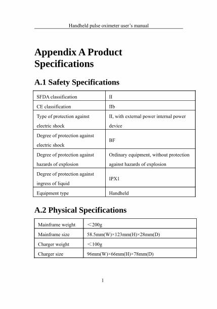
Appendix A Product Specifications
A.1 Safety Specifications
SFDA classification II
CE classification IIb
Type of protection against
electric shock
II, with external power internal power
device
Degree of protection against
electric shockBF
Degree of protection against
hazards of explosion
Ordinary equipment, without protection
against hazards of explosion
Degree of protection against
ingress of liquidIPX1
Equipment type Handheld
A.2 Physical Specifications
Mainframe weight <200g
Mainframe size 58.5mm(W)×123mm(H)×28mm(D)
Charger weight <100g
Charger size 96mm(W)×66mm(H)×78mm(D)
1

Handheld pulse oximeter user’s manual
AC-DC adapter
weight<200g
AC-DC adapter size 41.5mm(W)×90mm(H)×32mm(D)
A.3 Environmental Specifications
TemperatureOperating: 0℃ to +40℃;
Storage: -20℃ to +50℃;
Atmospheric
pressure
Operating: 860hPa to 1060hPa;
Storage: 500hPa to 1060hPa;
HumidityOperating: 15% to 85% (non condensing)
Storage: 10% to 93% (non condensing)
A.4 Charging Specifications
A.4.1 AC-DC Adapter (Optional)
Input 100~240VAC,50/60Hz
Output 5V ,1.5A
A.4.2 Battery Specification
Standard
Type Lithium ion rechargeable battery
Size 50mm×46.5 mm×13.5mm
2
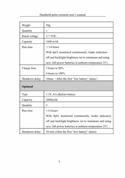
Handheld pulse oximeter user’s manual
Weight 50g
Quantity 1
Rated voltage 3.7 VDC
Capacity 1600 mAh
Run time >14 hours
With SpO2 monitored continuously, Audio indicators
off and backlight brightness set to minimum and using
new, full power batteries at ambient temperature 25℃.
Charge time 3 hours to 90%
4 hours to 100%
Shutdown delay 10min(After the first “low battery” alarm)
Optional
Type 1.5V, AA alkaline battery
Capacity 2000mAh
Quantity 3
Run time >14 hours
With SpO2 monitored continuously, Audio indicators
off and backlight brightness set to minimum and using
new, full power batteries at ambient temperature 25℃.
Shutdown delay 10 min (After the first “low battery” alarm)
3
Handheld pulse oximeter user’s manual
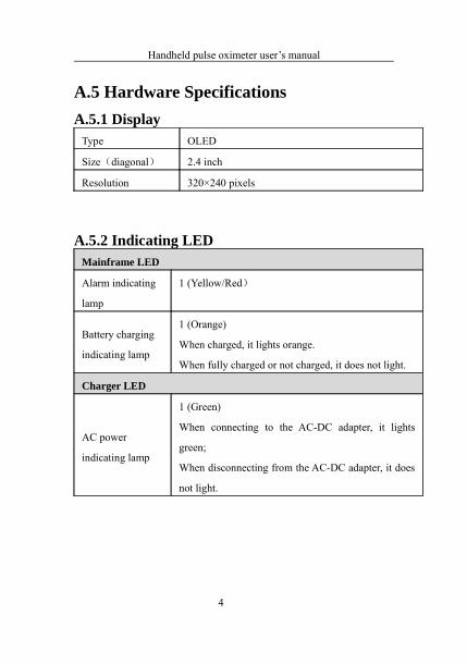
A.5 Hardware SpecificationsA.5.1 Display
Type OLED
Size(diagonal) 2.4 inch
Resolution 320×240 pixels
A.5.2 Indicating LEDMainframe LED
Alarm indicating
lamp
1 (Yellow/Red)
Battery charging
indicating lamp
1 (Orange)
When charged, it lights orange.
When fully charged or not charged, it does not light.
Charger LED
AC power
indicating lamp
1 (Green)
When connecting to the AC-DC adapter, it lights
green;
When disconnecting from the AC-DC adapter, it does
not light.
4

Handheld pulse oximeter user’s manual
A.5.3 Audio IndicatingSpeaker Gives audible alarm, button tone and beep tone
Supports Pitch Tone and multi-level volume;
Alarm tones meet the requirement of IEC 60601-1-8.
Alarm pressure 45 dB to 85 dB, Testing place is 1 meter from the
tone.
A.5.4 Buttons
Quantity 6
Functions Power button, Up button, Down button, Left button,
Right button, and Alarm pause button.
5
Handheld pulse oximeter user’s manual
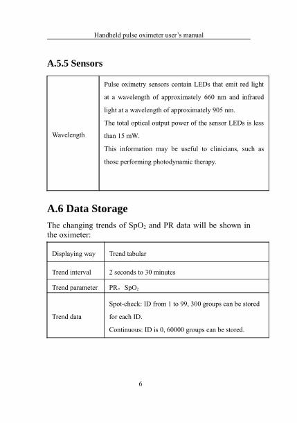
A.5.5 Sensors
Wavelength
Pulse oximetry sensors contain LEDs that emit red light
at a wavelength of approximately 660 nm and infrared
light at a wavelength of approximately 905 nm.
The total optical output power of the sensor LEDs is less
than 15 mW.
This information may be useful to clinicians, such as
those performing photodynamic therapy.
A.6 Data StorageThe changing trends of SpO2 and PR data will be shown in the oximeter:
Displaying way Trend tabular
Trend interval 2 seconds to 30 minutes
Trend parameter PR,SpO2
Trend data
Spot-check: ID from 1 to 99, 300 groups can be stored
for each ID.
Continuous: ID is 0, 60000 groups can be stored.
6

Handheld pulse oximeter user’s manual
A.7 Measurement Specifications
A.7.1 Digital SpO2
SpO2
Technic Digital SpO2 technic
Range 0~100%
Resolution 1%
Accuracy70% to 100%: ±2%
0% to 69%: unspecified
Refreshing rate <13 seconds
Pitch Tone with
PR
Range 25 bpm to 250 bpm
Resolution 1 bpm
Accuracy ±2% or ±1 bpm, whichever is the greater
Refreshing rate <13 seconds
7

Handheld pulse oximeter user’s manual
A.7.2 Nellcor SpO2
SpO2
Range 0% to 100%
Resolution 1%
Accuracy
70% to 100%: ±2%(adult/pediatric)
70% to 100%: ±3%(neonate)
70% to 100%: ±2%(low perfusion)
0% to 69%, unspecified
Refreshing rate 7s
Pitch Tone with
PR
Range 25 bpm to 250 bpm
Resolution 1 bpm
Accuracy ± 3 bpm
Refreshing rate 7s
A.7.3 Alarm Limit Specifications
Alarm limits Range (%) Step (%)
SpO2 high limit (low limit +1) to 1001
SpO2 low limit Desat to (high limit -1)
8

Handheld pulse oximeter user’s manual
Alarm limits Range (bpm) Step (bpm)
PR high limit (low limit +1) to 2501
PR low limit 20 to (high limit -1)
9
Handheld pulse oximeter user’s manual
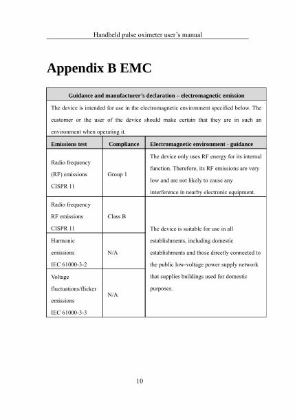
Appendix B EMC
10
Guidance and manufacturer’s declaration – electromagnetic emission
The device is intended for use in the electromagnetic environment specified below. The
customer or the user of the device should make certain that they are in such an
environment when operating it.
Emissions test Compliance Electromagnetic environment - guidance
Radio frequency
(RF) emissions
CISPR 11
Group 1
The device only uses RF energy for its internal
function. Therefore, its RF emissions are very
low and are not likely to cause any
interference in nearby electronic equipment.
Radio frequency
RF emissions
CISPR 11
Class B
The device is suitable for use in all
establishments, including domestic
establishments and those directly connected to
the public low-voltage power supply network
that supplies buildings used for domestic
purposes.
Harmonic
emissions
IEC 61000-3-2
N/A
Voltage
fluctuations/flicker
emissions
IEC 61000-3-3
N/A
Handheld pulse oximeter user’s manual
Guidance and Declaration – Electromagnetic Immunity
The device is suitable for use in the electromagnetic environment specified below. The
customer or the user of the device should make certain that they are in such an
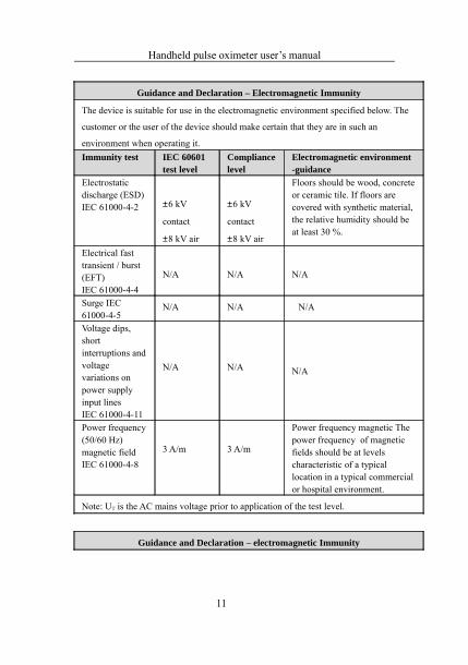
environment when operating it.Immunity test IEC 60601
test levelCompliance level
Electromagnetic environment -guidance
Electrostatic discharge (ESD)IEC 61000-4-2 ±6 kV
contact
±8 kV air
±6 kV
contact
±8 kV air
Floors should be wood, concrete or ceramic tile. If floors are covered with synthetic material, the relative humidity should be at least 30 %.
Electrical fast transient / burst(EFT)IEC 61000-4-4
N/A N/A N/A
Surge IEC 61000-4-5
N/A N/A N/A
Voltage dips, short interruptions and voltage variations on power supply input linesIEC 61000-4-11
N/A N/A N/A
Power frequency(50/60 Hz)magnetic fieldIEC 61000-4-8
3 A/m 3 A/m
Power frequency magnetic The power frequency of magnetic fields should be at levels characteristic of a typical location in a typical commercial or hospital environment.
Note: UT
is the AC mains voltage prior to application of the test level.
Guidance and Declaration – electromagnetic Immunity
11

Handheld pulse oximeter user’s manual
The device is suitable for use in the electromagnetic environment specified below.
The customer or the user of device should make certain that they are in such an
environment when operating it.
Immunity test IEC 60601 test level Compliance level
Conducted RF
IEC 61000-4-6N/A N/A
Radiated RF
IEC 61000-4-3
3 V/m
80 MHz to 2.5 GHz3 V/m
Electromagnetic environment - guidancePortable and mobile RF communications equipment should not be used closer to any part of the device, including cables, than the recommended separation distance. This is calculated from the equation applicable to the frequency of the transmitter.
PV
d ⎥⎦
⎤⎢⎣
⎡=
1
5.3
PE
d ⎥⎦
⎤⎢⎣
⎡=
1
5.3
80 MHz to 800 MHz
PE
d ⎥⎦
⎤⎢⎣
⎡=
1
7
800 MHz to 2.5 GHz
Where P is the maximum output power rating of the transmitter in watts (W)
according to the transmitter manufacturer and d is the recommended separation
distance in meters (m).
Field strengths from fixed RF transmitters, as determined by an electromagnetic site
surveya, should be less than the compliance level in each frequency rangeb.
Interference may occur in the vicinity of equipment marked with the following
symbol:
12

Handheld pulse oximeter user’s manual
NOTE 1 At 80 MHz and 800 MHz, the higher frequency range applies.
NOTE 2 These guidelines may not apply in all situations. Electromagnetic
propagation is affected by absorption and reflection from structures, objects and
people.
a Field strengths from fixed transmitters, such as base stations for radio
(cellular/cordless) telephones and land mobile radios, amateur radio, AM and
FM radio broadcast and TV broadcast cannot be predicted theoretically with
accuracy. To assess the electromagnetic environment due to fixed RF
transmitters, an electromagnetic site survey should be considered. If the
measured field strength in the location in which the device is used exceeds the
applicable RF compliance level above, the device should be observed to
verify normal operation. If abnormal performance is observed, additional
measures may be necessary, such as reorienting or relocating the device.
b Over the frequency range 150 kHz to 80 MHz, field strengths should be less than
3 V/m.
Recommended Separation Distances between Portable and Mobile RF
Communications Equipment and the SL-F SL Series Anti-decubitus Mattress
The device is intended for use in an electromagnetic environment in which radiated RF
disturbances are controlled. The customer or the user of the device can help prevent
electromagnetic interference by maintaining a minimum distance between portable and
mobile RF communications equipment (transmitters) and the device as recommended
below, according to the maximum output power of the communications equipment.
Rated maximum
output power of
Separation distance according to frequency of transmitter(m)
150 kHz to 80 MHz
80 MHz to 800 MHz
800 MHz to 2.5 GHz
13

Handheld pulse oximeter user’s manual
transmitter
(W)P
Vd ⎥
⎦
⎤⎢⎣
⎡=
1
5.3 PE
d ⎥⎦
⎤⎢⎣
⎡=
1
5.3 PE
d ⎥⎦
⎤⎢⎣
⎡=
1
7
0.01 1.2 0.12 0.23
0.1 3.8 0.38 0.73
1 12 1.2 2.3
10 38 3.8 7.3
100 120 12 23
For transmitters rated at a maximum output power not listed above, the recommended
separation distance d in metres (m) can be estimated using the equation applicable to the
frequency of the transmitter, where P is the maximum output power rating of the
transmitter in watts (W) according to the transmitter manufacturer.
NOTE 1 At 80 MHz and 800 MHz, the separation distance for the higher
frequency range applies.
NOTE 2 These guidelines may not apply in all situations. Electromagnetic
propagation is affected by absorption and reflection from structures, objects and people.
Appendix C Factory Defaults
This section lists the most important factory default
settings. These settings can be adjusted and you can load the
factory defaults if you need.
14

Handheld pulse oximeter user’s manual
C.1 Alarm Setup
Alarm Setup Factory Default
Alarm Vol 2
SpO2 Alarm Level Med
PR Alarm Level Med
C.2 System Setup
System Setup Factory Default
Beep Vol 2
Key Vol 2
Brightness 3
Scan Speed 25mm/s
C.3 SpO2 Setup
SpO2 Setup Adult Pediatric Neonate
SpO2 High Limit 100 100 95
SpO2 Low Limit 90 90 90
PR Setup Adult Pediatric Neonate
PR High Limit 120 160 200
PR Low Limit 50 75 100
15

Handheld pulse oximeter user’s manual
C.4 Trend Setup
Trend Setup Factory Default
Interval 30s
16
Handheld pulse oximeter user’s manual
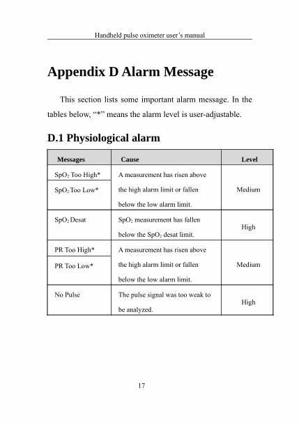
Appendix D Alarm Message
This section lists some important alarm message. In the
tables below, “*” means the alarm level is user-adjustable.
D.1 Physiological alarm
Messages Cause Level
SpO2 Too High* A measurement has risen above
the high alarm limit or fallen
below the low alarm limit.
MediumSpO2 Too Low*
SpO2 Desat SpO2 measurement has fallen
below the SpO2 desat limit.High
PR Too High* A measurement has risen above
the high alarm limit or fallen
below the low alarm limit.
MediumPR Too Low*
No Pulse The pulse signal was too weak to
be analyzed.High
17
Handheld pulse oximeter user’s manual
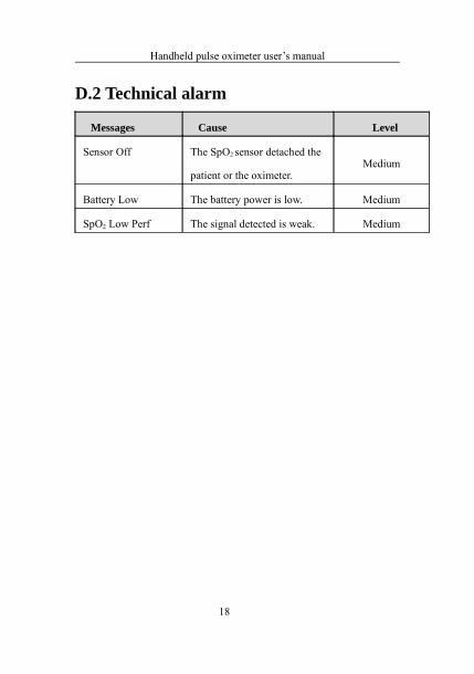
D.2 Technical alarm
Messages Cause Level
Sensor Off The SpO2 sensor detached the
patient or the oximeter.Medium
Battery Low The battery power is low. Medium
SpO2 Low Perf The signal detected is weak. Medium
18

Acare Technology Co., Ltd.Address: 6F.-6, No.5, Wuquan 1st Rd., Xinzhuang Dist.,
New Taipei City 242, Taiwan
TEL : +886-2-2298-8170
FAX : +886-2-2298-8560
Email: [email protected]: http://www.acaretech.com