agrimat - roots zone heating for nurseries
TRANSCRIPT
Table of Contents
Resilience Plus Installation guide. © 2015, all rights reserved P a g e | 1
35405037 | June 2015

Preface
Resilience Plus Installation guide. © 2015, all rights reserved P a g e | 2
PREFACE
Congratulations on your purchase of Resilience Plus natural chlorine generator with full automatic control of pH and
Chlorine. Your purchase will minimize the efforts needed to maintain your pool and maximize your enjoyment. The
system uses a very low concentration of salt (less than the concentration in a human teardrop) and converts it into
free chlorine that destroys algae and bacteria in the pool. After removing the algae and bacteria, the chlorine reverts
back into salt. This process of purification continues, making the need of adding extra sanitizing chemicals to the pool
virtually unnecessary.
Before installation or operation, please take the time to read this entire manual, compare package contents with the
parts list, and gather tools required. Improper installation may void the warranty and create unnecessary hazards.
This manual contains step-by-step instructions to help ensure that your installation meets the recommended
standards. Spending the time to understand your system and its functions will assure successful, trouble-free
operation. If you are unsure about any of the information in this manual, please contact your installer/dealer or feel
free to contact us directly. Additional information about your system can also be found at our website:
www.americansps.com.
When working around your pool, please take care to avoid hazards such as electrical wires and chemicals.
CAUTION! Safety comes first!
SAFETY INSTRUCTIONS
Read and follow all instructions
All electrical work must be performed by a licensed electrician and conform to all national, state, and local codes.
Improper use or installation can badly harm the unit and its surroundings. When installing and using electrical
equipment, basic safety precautions should always be followed, including the following:
DO NOT OPEN THE DISPLAY COVER OF THE CONTROL BOX – NOT A SERVICABLE UNIT.
● Disconnect all AC power before installation.
● WARNING – to reduce the risk of injury, do not permit children to use this product.
● The Control Box must be mounted vertically on a flat surface and at a minimum horizontal distance of 5 ft
(1.5m)(or more, if local codes require so) from the pool.
● WARNING – risk of electric shock! Connect only to a grounding type circuit protected by a ground-fault
circuit-interrupter (GFCI) outlet. The installer should provide this GFCI requirement. The GFCI should be
rated for minimum 6 Amps and tested on a regular basis by pushing the test button. If the GFCI fails to
operate correctly, there is ground current flowing indicating the possibility of electric shock. Do not use this
unit. Disconnect unit and have a qualified professional fix the problem before using.
● The Input circuit (LN1 & N/LN1) must be connected only after OVERCURRENT DEVICES, such as fuse or
circuit breaker to limit the amperage in the input wire to the maximum that is permitted by the National
electrical Code.
● The Unit must be permanently connected, with copper wire, not less than 14 AWG (1.5 mm²).
● Do not bury the cord. Place the cord so to minimize damage by lawn mowers, hedge trimmer and other
equipment.
Preface
Resilience Plus Installation guide. © 2015, all rights reserved P a g e | 3
● WARNING! To reduce the risk of electric shock, replace a damaged cord immediately.
● WARNING! To reduce the risk of electric shock, do not use an extension cord to connect the unit to
electric power supply; provide a properly located outlet.
● Wiring of the unit must be performed according to the wiring instructions detailed in this manual or on
the front box cover.
● Build-up of flammable fumes can result in a hazardous condition if the cell is allowed to operate without
flow. This device must be operated only with the original in-line flow sensor.
● The Flow Sensor must be installed between the last piece of apparatus and the cell.
● Ensure that equipment and materials used in or around the pool and spa are compatible with salt-based
sanitation systems. Certain materials may be susceptible to salt and chlorine damage.
● ALWAYS ADD ACID TO WATER, NEVER WATER TO ACID.
● KEEP THESE INSTRUCTIONS.

Preface
Resilience Plus Installation guide. © 2015, all rights reserved P a g e | 4
TABLE OF CONTENTS
PREFACE ....................................................................................................................................................................................... 2
Safety instructions ............................................................................................................................................................................ 2
BASIC OPERATION ........................................................................................................................................................................ 6
Turning the unit on ........................................................................................................................................................................... 7
Operating actions ............................................................................................................................................................................. 8
Changing the pH set-point ............................................................................................................................................................ 8
Changing the ORP set-point ......................................................................................................................................................... 8
Automatic ST:BY Mode ................................................................................................................................................................. 9
Salinity readout ................................................................................................................................................................................. 9
Normal salt level ........................................................................................................................................................................... 9
High salinity indication ............................................................................................................................................................... 10
Low salinity indication ................................................................................................................................................................ 10
Turbo setting .............................................................................................................................................................................. 11
Pool cover function ......................................................................................................................................................................... 12
CALIBRATING PH SENSOR ........................................................................................................................................................... 12
MANUAL PH CONTROL ............................................................................................................................................................... 13
Manualy reducing the pH ............................................................................................................................................................... 13
pH reducing: Manual .................................................................................................................................................................. 13
Cell cleaning mode .......................................................................................................................................................................... 13
Adjusting the frequency of the cleaning .................................................................................................................................... 13
Immediately initiating a cell cleaning ......................................................................................................................................... 14
ACID PIPE reminder ........................................................................................................................................................................ 14
ERROR MESSAGES ...................................................................................................................................................................... 14
NO FLOW ........................................................................................................................................................................................ 14
HIGH TEMPERATURE IN THE UNIT .................................................................................................................................................. 15
LOW TEMP ...................................................................................................................................................................................... 15
SHRT CELL ....................................................................................................................................................................................... 15
NO CELL ........................................................................................................................................................................................... 15
NEED PUMP .................................................................................................................................................................................... 15
ACID PIPE ........................................................................................................................................................................................ 15
pH alarm high limit ......................................................................................................................................................................... 16
pH alarm low limit .......................................................................................................................................................................... 16
ORP alarm high limit ....................................................................................................................................................................... 16
ORP alarm low limit ........................................................................................................................................................................ 16
no card alarm .................................................................................................................................................................................. 16
pH probe ......................................................................................................................................................................................... 16
ORP probe ....................................................................................................................................................................................... 16
MAINTENANCE ........................................................................................................................................................................... 17
Control box ..................................................................................................................................................................................... 17
water ............................................................................................................................................................................................... 17
cell maintenance ............................................................................................................................................................................. 17
Cell cleaning ............................................................................................................................................................................... 17
Cleaning using the cleaning cap ................................................................................................................................................. 18
Preface
Resilience Plus Installation guide. © 2015, all rights reserved P a g e | 5
Sensor maintenance ....................................................................................................................................................................... 18
Sensor replacement ........................................................................................................................................................................ 19
Sensor storage ................................................................................................................................................................................ 19
WINTERIZING ............................................................................................................................................................................. 19
SPRING STARTUP ........................................................................................................................................................................ 19
SALT LEVELS SETTINGS ................................................................................................................................................................ 20
Before adding the salt..................................................................................................................................................................... 20
Adding the salt ................................................................................................................................................................................ 20
Calculating the size of the pool .................................................................................................................................................. 21
Salinity demand table (in lbs.) .................................................................................................................................................... 21
REPLACING THE PREISTALTIC TUBE OF THE PH CLEAR ................................................................................................................. 22
UNDERSTANDING THE CHEMISTRY ............................................................................................................................................. 24
GENERAL TROUBLESHOOTING .................................................................................................................................................... 26
RESILIENCE PLUS TROUBLESHOOTING ........................................................................................................................................ 30
PH CLEAR SYSTEM TROUBLESHOOTING ...................................................................................................................................... 33
Basic operation
Resilience Plus Installation guide. © 2015, all rights reserved P a g e | 6
BASIC OPERATION
Resilience Plus produces a pure form of chlorine to sanitize and oxidize the pool water. The chlorine residual needs to
be maintained at 1 to 3 ppm. This may be tested using a standard kit or by your local pool store. To obtain the optimal
residual buildup of chlorine, the best time to run your filter is in the early morning and after 4pm when there is less
UV to destroy the chlorine produced, leaving chlorine in the pool to oxidize the unwanted foreign matter.
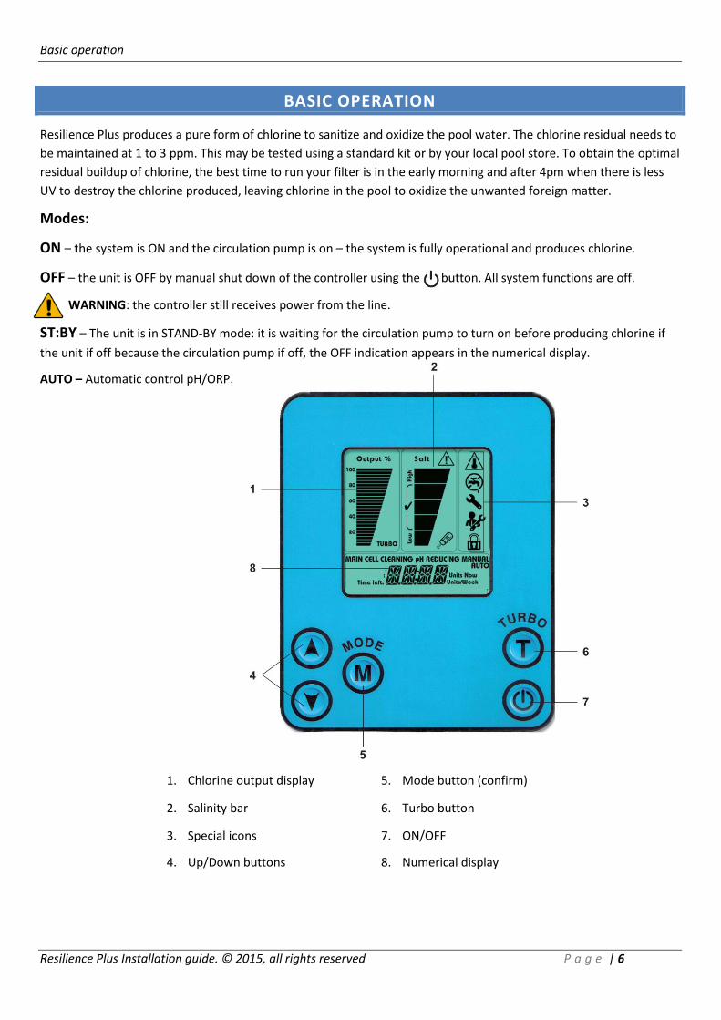
Modes:
ON – the system is ON and the circulation pump is on – the system is fully operational and produces chlorine.
OFF – the unit is OFF by manual shut down of the controller using the button. All system functions are off.
WARNING: the controller still receives power from the line.
ST:BY – The unit is in STAND-BY mode: it is waiting for the circulation pump to turn on before producing chlorine if
the unit if off because the circulation pump if off, the OFF indication appears in the numerical display.
AUTO – Automatic control pH/ORP.
1. Chlorine output display 5. Mode button (confirm)
2. Salinity bar 6. Turbo button
3. Special icons 7. ON/OFF
4. Up/Down buttons 8. Numerical display

Basic operation
Resilience Plus Installation guide. © 2015, all rights reserved P a g e | 7
TURNING THE UNIT ON
1. Ensure that the main circulation pump is on.
2. Press the button.
3. The controller turns on and automatically executes the following actions:
- The system goes to the last setting before it was turned off
- The main screen is active
- Turbo time (if previously in this mode) goes back to zero (initialized).
- The system measures the water's salinity and only after ~1 minute
displays it.
Make sure all readings are ok:
- The salinity bar indicators are on at normal level (the salinity readout takes a
little longer to display as the water has to be tested)
- AUTO indication appears in the numerical display
To see the current readings of the pH and ORP sensors press either the or
arrows.
The first time one of the buttons is pressed the pH values are displayed.
The second time one of the buttons is pressed the ORP readings are visible. The readings will be displayed for a few
seconds before returning to AUTO display.
pH feed output is activated when the measured pH is greater than the pH set point, indicating the need to feed acid
to decrease the pH of the water. The display will show "pH REDUCING" blinking:
Chlorine output is activated when the measured ORP is below the ORP set point, indicating the
need to generate more chlorine to meet the values of the set point. The "Output %"area on the
LCD display will appear. System automatically begins producing chlorine to reach the set point.
The "Output %" area on the LCD display is only visible when chlorine is being generated by the
system.
FROM NOW ON THE SYSTEM WILL BE OPERATING AUTOMATICALLY, MONITORING THE WATER
CHEMISTRY AND PRODUCTING CHLORINE UPON DEMAND!
Basic operation
Resilience Plus Installation guide. © 2015, all rights reserved P a g e | 8
OPERATING ACTIONS
In order to change the operation statuses of the system use the following operating actions:
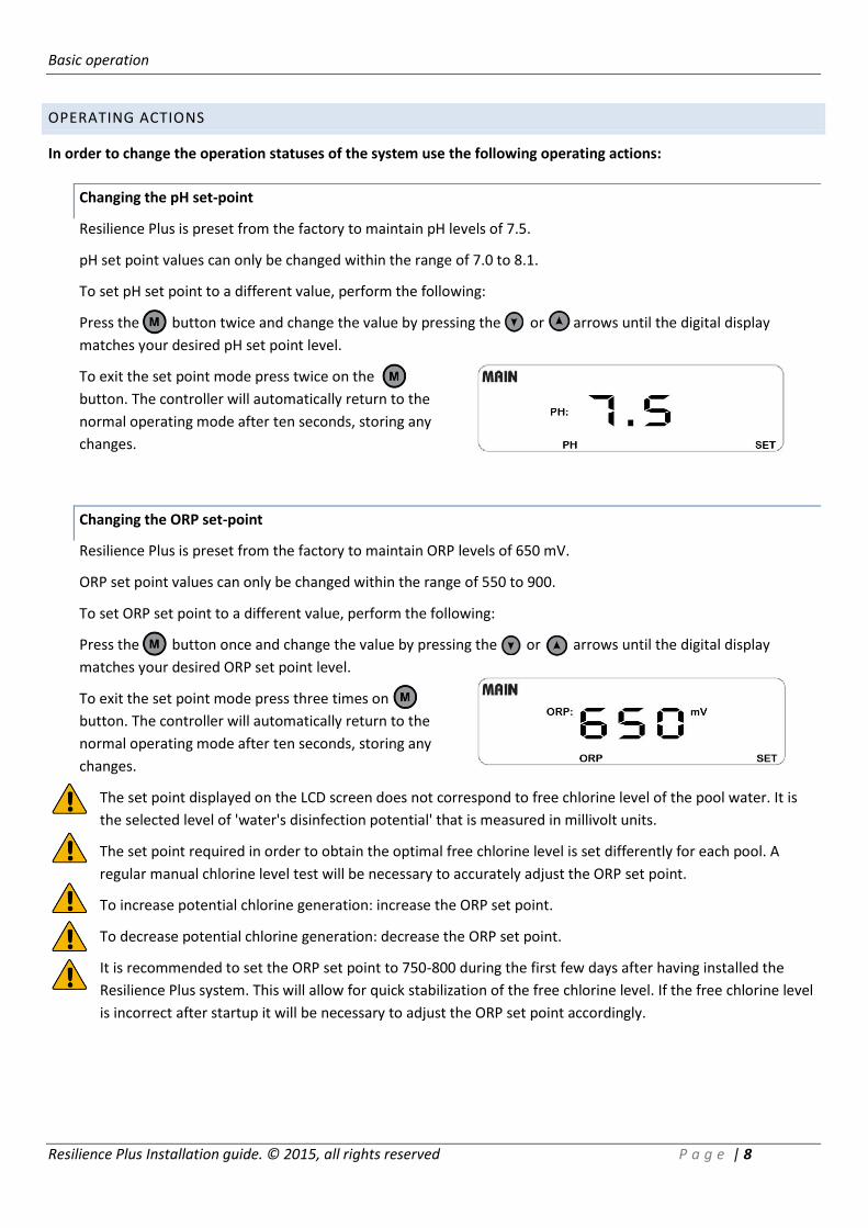
Changing the pH set-point
Resilience Plus is preset from the factory to maintain pH levels of 7.5.
pH set point values can only be changed within the range of 7.0 to 8.1.
To set pH set point to a different value, perform the following:
Press the button twice and change the value by pressing the or arrows until the digital display
matches your desired pH set point level.
To exit the set point mode press twice on the
button. The controller will automatically return to the
normal operating mode after ten seconds, storing any
changes.
Changing the ORP set-point
Resilience Plus is preset from the factory to maintain ORP levels of 650 mV.
ORP set point values can only be changed within the range of 550 to 900.
To set ORP set point to a different value, perform the following:
Press the button once and change the value by pressing the or arrows until the digital display
matches your desired ORP set point level.
To exit the set point mode press three times on the
button. The controller will automatically return to the
normal operating mode after ten seconds, storing any
changes.
The set point displayed on the LCD screen does not correspond to free chlorine level of the pool water. It is
the selected level of 'water's disinfection potential' that is measured in millivolt units.
The set point required in order to obtain the optimal free chlorine level is set differently for each pool. A
regular manual chlorine level test will be necessary to accurately adjust the ORP set point.
To increase potential chlorine generation: increase the ORP set point.
To decrease potential chlorine generation: decrease the ORP set point.
It is recommended to set the ORP set point to 750-800 during the first few days after having installed the
Resilience Plus system. This will allow for quick stabilization of the free chlorine level. If the free chlorine level
is incorrect after startup it will be necessary to adjust the ORP set point accordingly.

Basic operation
Resilience Plus Installation guide. © 2015, all rights reserved P a g e | 9
Automatic ST:BY Mode
When the main circulation pump turns off the controller shuts down the current supply to the chlorinator
cell. "ST:BY" display appears in the numerical display. This action is a safety action that prevents chlorine
production without flow in the chlorinator cell.
In ST:BY mode: the CELL CLEANING of the pH Clear is accessible as well as the option to calibrate the pH
sensor (see "Calibrating pH sensor", page 12).
Unit turns ON from ST:BY Mode:
When the main circulation pump will turn on, the chlorinator will revert back
to AUTO position.
- The system goes to the former setting before it was turned off.
- The main screen is active.
- The system goes back to the former setting in soft-start mode (i.e. slowly
increasing the output from 0 to the former setting).
- Turbo time (if previously in this mode) continues to count back its
remaining time.
SALINITY READOUT
NOTE: the salt readout takes up to one minute to test and display the salt level.
NOTE: The chlorinator cell should be tested as lime-scale build up on its blades may affect the readings.
Clean the blades if necessary. If the cell is clean and readings are still inaccurate please refer to the
troubleshooting section of this guide, page 25.
Normal salt level
When salt level is between the recommended ranges of
2800-4700 ppm the salinity bar is in the (√ icon) area.
Basic operation
Resilience Plus Installation guide. © 2015, all rights reserved P a g e | 10
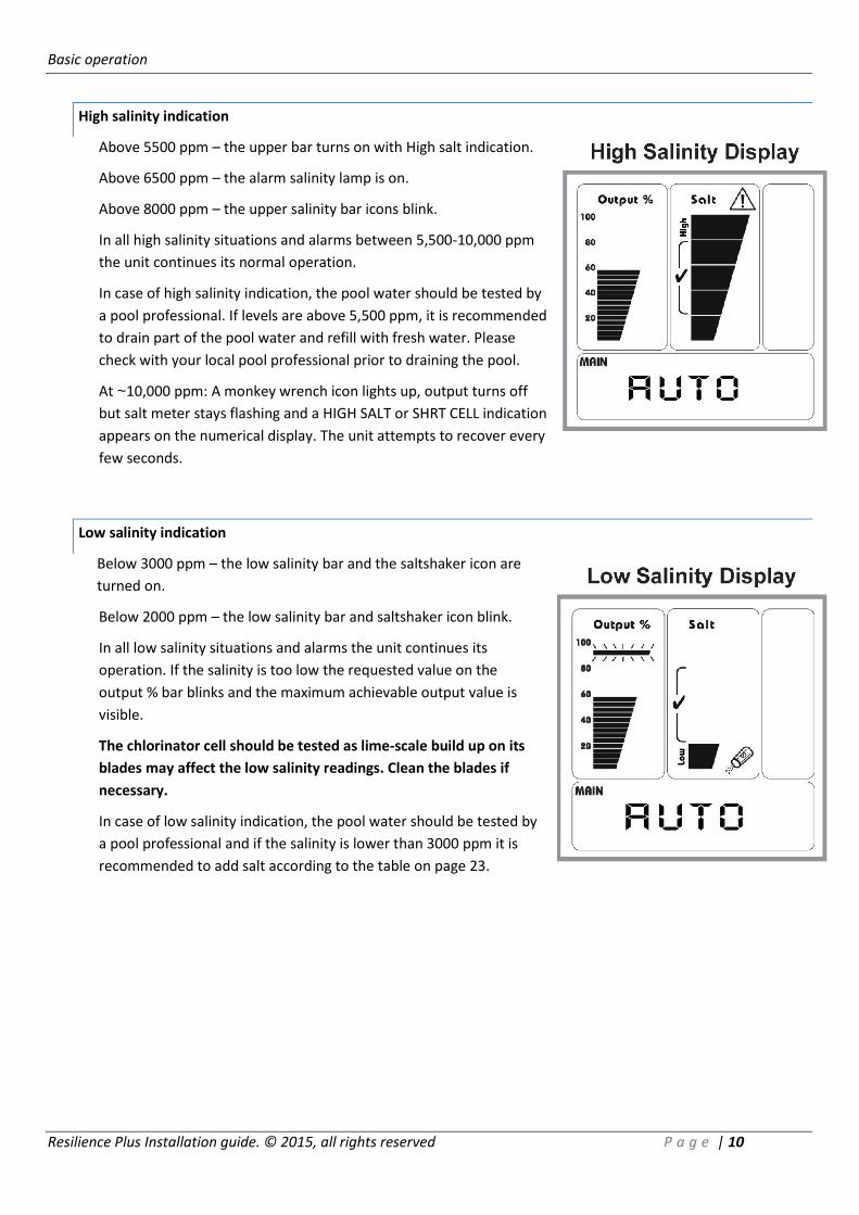
High salinity indication
Above 5500 ppm – the upper bar turns on with High salt indication.
Above 6500 ppm – the alarm salinity lamp is on.
Above 8000 ppm – the upper salinity bar icons blink.
In all high salinity situations and alarms between 5,500-10,000 ppm
the unit continues its normal operation.
In case of high salinity indication, the pool water should be tested by
a pool professional. If levels are above 5,500 ppm, it is recommended
to drain part of the pool water and refill with fresh water. Please
check with your local pool professional prior to draining the pool.
At ~10,000 ppm: A monkey wrench icon lights up, output turns off
but salt meter stays flashing and a HIGH SALT or SHRT CELL indication
appears on the numerical display. The unit attempts to recover every
few seconds.
Low salinity indication
Below 3000 ppm – the low salinity bar and the saltshaker icon are
turned on.
Below 2000 ppm – the low salinity bar and saltshaker icon blink.
In all low salinity situations and alarms the unit continues its
operation. If the salinity is too low the requested value on the
output % bar blinks and the maximum achievable output value is
visible.
The chlorinator cell should be tested as lime-scale build up on its
blades may affect the low salinity readings. Clean the blades if
necessary.
In case of low salinity indication, the pool water should be tested by
a pool professional and if the salinity is lower than 3000 ppm it is
recommended to add salt according to the table on page 23.
Basic operation
Resilience Plus Installation guide. © 2015, all rights reserved P a g e | 11
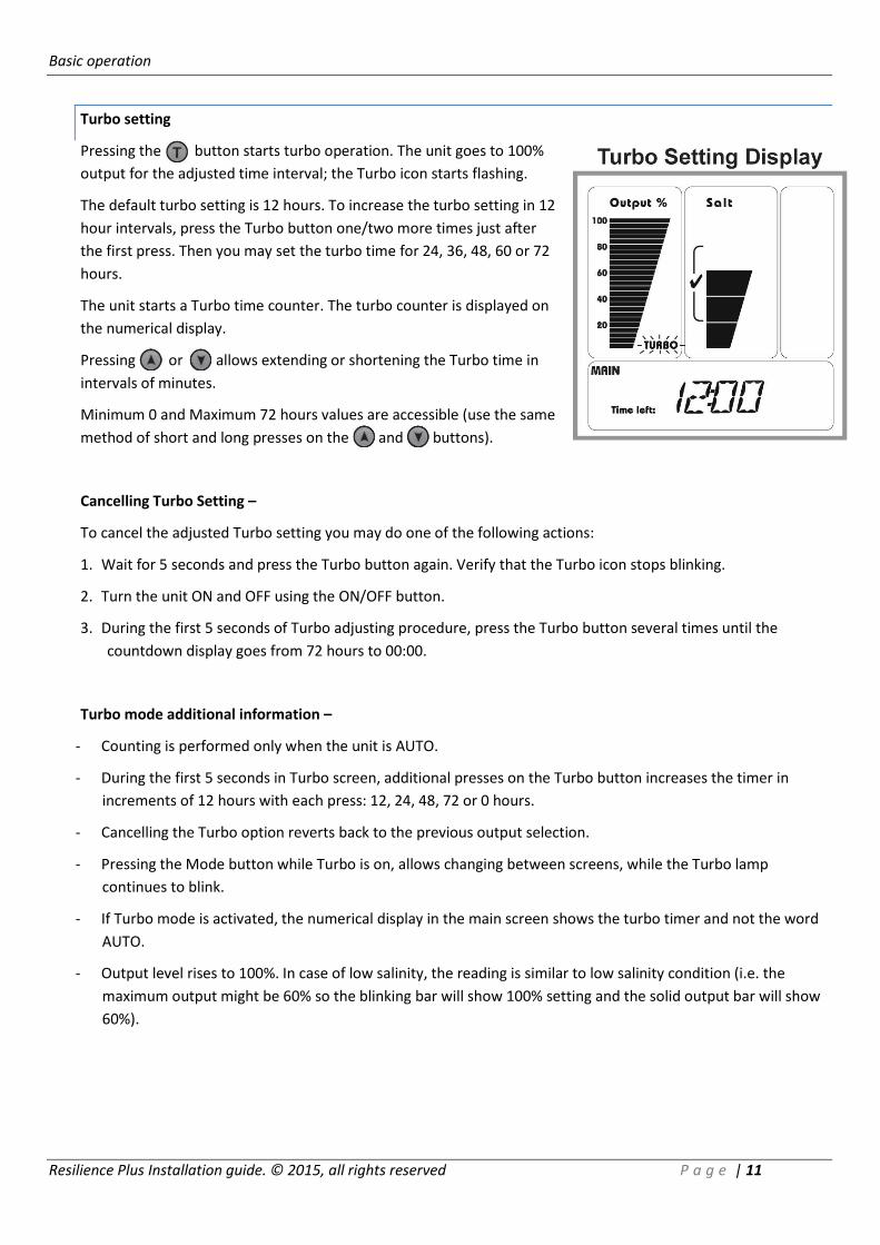
Turbo setting
Pressing the button starts turbo operation. The unit goes to 100%
output for the adjusted time interval; the Turbo icon starts flashing.
The default turbo setting is 12 hours. To increase the turbo setting in 12
hour intervals, press the Turbo button one/two more times just after
the first press. Then you may set the turbo time for 24, 36, 48, 60 or 72
hours.
The unit starts a Turbo time counter. The turbo counter is displayed on
the numerical display.
Pressing or allows extending or shortening the Turbo time in
intervals of minutes.
Minimum 0 and Maximum 72 hours values are accessible (use the same
method of short and long presses on the and buttons).
Cancelling Turbo Setting –
To cancel the adjusted Turbo setting you may do one of the following actions:
1. Wait for 5 seconds and press the Turbo button again. Verify that the Turbo icon stops blinking.
2. Turn the unit ON and OFF using the ON/OFF button.
3. During the first 5 seconds of Turbo adjusting procedure, press the Turbo button several times until the
countdown display goes from 72 hours to 00:00.
Turbo mode additional information –
- Counting is performed only when the unit is AUTO.
- During the first 5 seconds in Turbo screen, additional presses on the Turbo button increases the timer in
increments of 12 hours with each press: 12, 24, 48, 72 or 0 hours.
- Cancelling the Turbo option reverts back to the previous output selection.
- Pressing the Mode button while Turbo is on, allows changing between screens, while the Turbo lamp
continues to blink.
- If Turbo mode is activated, the numerical display in the main screen shows the turbo timer and not the word
AUTO.
- Output level rises to 100%. In case of low salinity, the reading is similar to low salinity condition (i.e. the
maximum output might be 60% so the blinking bar will show 100% setting and the solid output bar will show
60%).
Calibrating pH sensor
Resilience Plus Installation guide. © 2015, all rights reserved P a g e | 12
POOL COVER FUNCTION
The unique pool cover function enables the chlorinator to reduce the chlorine output while the pool is covered.
When the pool cover is over the pool, the chlorinator will automatically reduce its chlorine output to 20% of the
maximum level and an "AUX MODE" message will appear on the numerical display.
Pressing and buttons while the system is in pool cover mode enables to permanently set new output values
to the unit while the pool is covered (e.g. the default setting is 20% total, but when the pools is covered you may
change the default setting to be 40%. The setting will remain 40% for the next pool covering occurrences). In order to
activate this function properly, make sure the control box is getting a dry contact from the pool cover control while
the pool is covered.
CALIBRATING PH SENSOR
The pH sensor has been calibrated before leaving the factory, however, in order for the sensor to operate reliably and
accurately it is imperative to calibrate the sensor before operating the system. The calibration will be executed by
immersing the sensor in two different pH solutions: pH 7.0 and pH 4.0 solutions.
Make sure the control box is connected to the main power supply and in ST:BY mode. Turn off the pool pump.
Remove the pH sensor from its holder by unscrewing the black collar. Rinse the sensor with tap water and shake it to
remove any excess water. Do not touch or wipe the glass with a cloth as it may damage the sensor!
1. Place the pH sensor in a buffer of pH 7.0 solution and stir the electrode in the solution several times.
2. Leave the pH sensor immersed in the solution for approximately 2 minutes in order to ensure reliable
readings.
3. Turn off the control box by pressing the button. The LCD display will show "OFF".
4. Press the button to enter calibration mode.
5. Wait several seconds until the pH values are stable. Press on the button to confirm the readings.
6. Remove the pH sensor from the pH 7.0 buffer solution. Rinse the sensor with tap water and shake it to
remove any excess water. Do not touch or wipe the glass with a cloth as it may damage the sensor!
7. Place the pH sensor in a buffer of pH 4.0 solution and stir the electrode in the solution several times.
8. Wait several seconds until the pH values are stable. Press on the button to confirm the readings.
9. The LCD display will show "DONE".
Calibration process is completed.
It is recommended to perform calibration at least once every two months during the swimming season.
Before starting the calibration process, ensure that the pH sensor is perfectly clean, and then rinse it with
clear water. This will ensure that the calibration process is more accurate.
Manual pH control
Resilience Plus Installation guide. © 2015, all rights reserved P a g e | 13
MANUAL PH CONTROL
The pH Clear dosing acid pump enables the system to reduce pH levels manually by periodically infusing small
amounts of acid into the pool. More acid in the water balances the pH levels, less acid units allow pH to rise.
MANUALY REDUCING THE PH
Ensure that the circulation pump is ON, then press the "MODE" button three times to go to the "pH reducing:
Manual" mode.
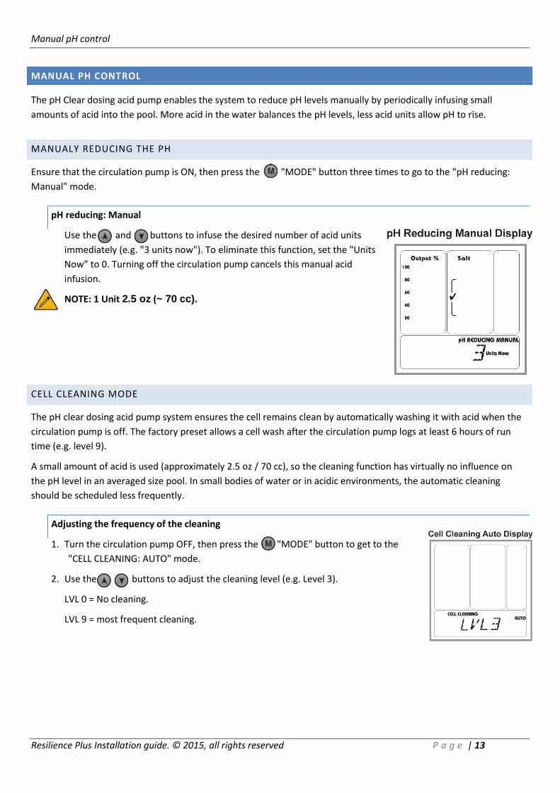
pH reducing: Manual
Use the and buttons to infuse the desired number of acid units
immediately (e.g. "3 units now"). To eliminate this function, set the "Units
Now" to 0. Turning off the circulation pump cancels this manual acid
infusion.
NOTE: 1 Unit 2.5 oz (~ 70 cc).
CELL CLEANING MODE
The pH clear dosing acid pump system ensures the cell remains clean by automatically washing it with acid when the
circulation pump is off. The factory preset allows a cell wash after the circulation pump logs at least 6 hours of run
time (e.g. level 9).
A small amount of acid is used (approximately 2.5 oz / 70 cc), so the cleaning function has virtually no influence on
the pH level in an averaged size pool. In small bodies of water or in acidic environments, the automatic cleaning
should be scheduled less frequently.
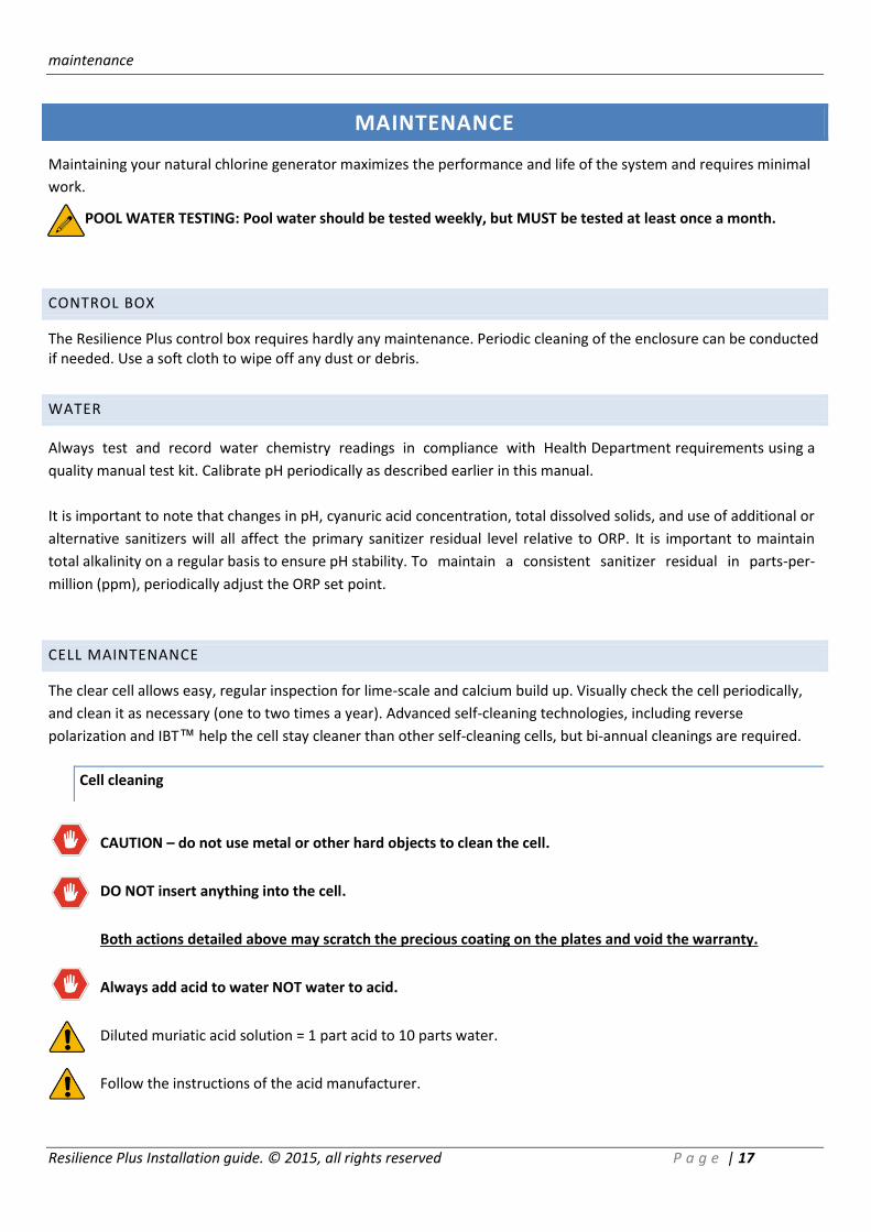
Adjusting the frequency of the cleaning
1. Turn the circulation pump OFF, then press the "MODE" button to get to the
"CELL CLEANING: AUTO" mode.
2. Use the buttons to adjust the cleaning level (e.g. Level 3).
LVL 0 = No cleaning.
LVL 9 = most frequent cleaning.

error messages
Resilience Plus Installation guide. © 2015, all rights reserved P a g e | 14
Immediately initiating a cell cleaning
1. Turn the circulation pump OFF, then press the "MODE" button to get to the
"CELL CLEANING: MANUAL" mode.
2. Use the buttons to adjust the cleaning level (e.g. Level 3).
LVL 1 uses 1 unit of acid.
LVL 4 uses 4 units of acid.
NOTE: the cleaning process can take more than 1 hour. If the cell remains calcified, purge it out by turning
the circulation pump on for a few minutes, and then repeat the cleaning function.
Turning the circulation pump ON cancels this manual cleaning function.
NOTE: In cases that the automatic settings of the pH Clear system does not reduce the pool's pH level or
doesn't keep the cell clear, make sure that the acid container is full and that the suction tube is installed
properly.
ACID PIPE REMINDER
The Preistaltic tube of the pH Clear unit requires replacing every 180 days, therefore the system is set to begin
counting down 180 days upon first operation. An "ACID PIPE" message appears on the numerical display every 180
days, when the Preistaltic tube requires replacing, see "Replacing the peristaltic tube of the pH Clear" chapter, page
20.
Once the Preistaltic tube is replaced the 180 days counter needs to be reset. To reset it do the following:
1. Press the "MODE" button four times. ACID PIPE will display again.
2. Press the button once. A "NEW PIPE" and "180 DAYS" message will be displayed.
3. The systems default is to display a reminder every 180 days (recommended). Use the buttons to
decrease the number of days in steps of 10 days. Once set, confirm by pressing the button once.
ERROR MESSAGES
NO FLOW
The "faucet" icon is displayed and "NO FLOW" message appears on the numerical display.
If the faucet icon blinks it means that the flow switch is in "transient" position. Wait a few
seconds for the icon to stop blinking and remain on the display. If the icon continues to blink,
verify that you have proper flow without air bubbles in the cell pipeline.
NOTE: For installations with flow below 25 GPM (3 m³/h) a "low flow" switch must
be obtained from the manufacturer.
error messages
Resilience Plus Installation guide. © 2015, all rights reserved P a g e | 15
HIGH TEMPERATURE IN THE UNIT
High temperature icon will be turned on when unit temperature is higher than 149°F.
If the temperature is higher than 158 °F the control unit will reduce the chlorine output to 50%. The
system will return to the full adjusted power and turn off the high temp icon when the unit
temperature drops back below 149 °F.
LOW TEMP
In case of low water temperature below 59 °F the unit will display "LOW TEMP" message on the numerical display
and will reduce power output to maximum 50%.
If the water temperature drops below 50 °F the unit will reduce power output to maximum 25%.
NOTE: If the water temperature sensor is not connected, the unit is preset for water temperature of 79 °F.
Refraining from wiring the temperature sensor may cause deviation in the salinity readings and may damage
the cell in low water temperatures.
SHRT CELL
If the cell cable is shorted by some way or the salinity is much too high (above 10,000 ppm) a "SHRT CELL" indication
will appear on the numerical display. The unit will reduce the power output to 0. The unit will attempt to recover
from this state every few seconds and will automatically detect when the short is removed or the salinity is reduced.
NO CELL
If the cable is disconnected, the salinity is much too low (below 1000 ppm) or the cell has collected large amounts of
scale deposits a "NO CELL" indication will appear on the numerical display and the unit will reduce the power output
to 0. The unit will attempt to recover from this state every few seconds and will automatically detect when the cable
is reconnected or the salinity and/or lime-scale is removed.
NEED PUMP
If the unit is attempting to reach the pH Clear system when the pump is disconnected a "NEED PUMP" message
appears on the numerical display. The unit will automatically detect if the pH Clear system is connected.
ACID PIPE
The Preistaltic tube of the pH Clear unit requires replacing every 180 days. An "ACID PIPE" message appears on the
numerical display when the Preistaltic tube requires replacing.
error messages
Resilience Plus Installation guide. © 2015, all rights reserved P a g e | 16
PH ALARM HIGH LIMIT
"PH HIGH" - When the measured pH value is higher than the limit of 8.5 pH, the LCD will show "PH HIGH". The acid
pump continues to draw acid despite the alarm display.
The alarm will be cleared automatically when the measured pH value returns to within the non-alarm range (7.0-8.1 pH).
PH ALARM LOW LIMIT
"PH LOW" - When the measured pH value is less than the limit of 6.7 pH, the LCD will show "PH LOW".
The alarm will be cleared automatically when the measured pH value returns to within the normal pH range (7.0-8.1 pH).
ORP ALARM HIGH LIMIT
"ORP HIGH" - When the measured ORP value is higher than the limit of 925 mV, the LCD will show "ORP HIGH".
The alarm will automatically disappear when the measured ORP value returns to within the non-alarm range (525-925mV).
ORP ALARM LOW LIMIT
"ORP LOW" - When the measured ORP value is lower than the limit of 525 mV, the LCD will show "ORP LOW".
The alarm will automatically disappear when the measured ORP value returns to within the normal range (525-925mV).
NO CARD ALARM
"NO CARD" –pH/ORP card is not detected when AUTO mode is enabled.
PH PROBE
"PH PROBE" – pH sensor is not detected.
ORP PROBE
"ORP PROBE" – ORP sensor is not detected.
maintenance
Resilience Plus Installation guide. © 2015, all rights reserved P a g e | 17
MAINTENANCE
Maintaining your natural chlorine generator maximizes the performance and life of the system and requires minimal
work.
POOL WATER TESTING: Pool water should be tested weekly, but MUST be tested at least once a month.
CONTROL BOX
The Resilience Plus control box requires hardly any maintenance. Periodic cleaning of the enclosure can be conducted if needed. Use a soft cloth to wipe off any dust or debris.
WATER
Always test and record water chemistry readings in compliance with Health Department requirements using a
quality manual test kit. Calibrate pH periodically as described earlier in this manual.
It is important to note that changes in pH, cyanuric acid concentration, total dissolved solids, and use of additional or
alternative sanitizers will all affect the primary sanitizer residual level relative to ORP. It is important to maintain
total alkalinity on a regular basis to ensure pH stability. To maintain a consistent sanitizer residual in parts-per-
million (ppm), periodically adjust the ORP set point.
CELL MAINTENANCE
The clear cell allows easy, regular inspection for lime-scale and calcium build up. Visually check the cell periodically,
and clean it as necessary (one to two times a year). Advanced self-cleaning technologies, including reverse
polarization and IBT™ help the cell stay cleaner than other self-cleaning cells, but bi-annual cleanings are required.
Cell cleaning
CAUTION – do not use metal or other hard objects to clean the cell.
DO NOT insert anything into the cell.
Both actions detailed above may scratch the precious coating on the plates and void the warranty.
Always add acid to water NOT water to acid.
Diluted muriatic acid solution = 1 part acid to 10 parts water.
Follow the instructions of the acid manufacturer.

maintenance
Resilience Plus Installation guide. © 2015, all rights reserved P a g e | 18
Cleaning using the cleaning cap
1. Disconnect the wires connecting the control box to the cell.
2. Remove the cell from the line by unthreading the barrel unions from the cell ends.
3. Remove the black O'ring on one end of the cell.
4. Attach the cell cleaning cap to the other end of the cell.
5. Pour into the cell, either undiluted white distilled vinegar, or a solution of diluted muriatic acid (one part
muriatic acid to 10 parts water).
6. Wait for foaming to stop (5-10 minutes when using muriatic acid; vinegar takes longer).
7. Safely dispose of the acid solution by pouring it into your pool.
8. Rinse the cell with water hose.
9. Put the O'ring back in place and re-install the cell in the line.
10. Reconnect the wires from the control box to the connectors at the sides of the cell until they "click" together.
SENSOR MAINTENANCE
The sensors must be clean and free from oil, chemical deposits and contamination to function properly. After
saturation in pool, the sensors may need to be cleaned on a weekly or monthly basis depending on bather load and
other facility specific characteristics. Slow response, increased need to calibrate pH, and inconsistent readings are
indications that the sensors are in need of cleaning.
To clean the sensors, disconnect from the Tee holder and carefully remove them. Wash the edge of the sensor with
tap water to eliminate any debris caught or stuck to it.
In the ORP sensor replace teflon thread-seal tape, and reinstall sensors. Hand tighten only.
Never allow a pH or ORP sensor to dry completely. Drying will damage the reference junction and void
the sensors warranty.
Winterizing
Resilience Plus Installation guide. © 2015, all rights reserved P a g e | 19
SENSOR REPLACEMENT
pH and ORP sensors are designed to provide the highest performance and longest service life. If sensors are properly
cleaned but provide unstable readings or require excessive calibration, they should be replaced.
SENSOR STORAGE
Exposure to atmospheric conditions will cause the sensor tips to dry out. if sensors are to be removed or stored for
one hour or longer, always remove and properly store them in their original bottles. Sensors must be protected
from freezing temperatures when not in use.
Store sensors in their original bottles, making sure that each one is filled with the original storage solution or clean
water. If the storage containers have been misplaced, store sensors individually in small glass or plastic containers
with clean water covering sensor tips.
WINTERIZING
Just like the pool plumbing, freezing may damage the system cell and flow sensor. If severe or extended periods of
freezing temperatures may occur, drain all water from the pump, filter, cell, supply and return lines before
temperatures drop.
The sensors should be prepared for storage as outlined above and protected from freezing temperatures.
SPRING STARTUP
DO NOT turn on the system until the pools' water chemistry has been brought to the required levels. See the "Turning
the Unit On" chapter on page 7 for more information.
Salt levels settings
Resilience Plus Installation guide. © 2015, all rights reserved P a g e | 20
SALT LEVELS SETTINGS
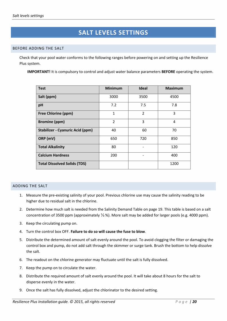
BEFORE ADDING THE SALT
Check that your pool water conforms to the following ranges before powering on and setting up the Resilience
Plus system.
IMPORTANT! It is compulsory to control and adjust water balance parameters BEFORE operating the system.
Test Minimum Ideal Maximum
Salt (ppm) 3000 3500 4500
pH 7.2 7.5 7.8
Free Chlorine (ppm) 1 2 3
Bromine (ppm) 2 3 4
Stabilizer - Cyanuric Acid (ppm) 40 60 70
ORP (mV) 650 720 850
Total Alkalinity 80 - 120
Calcium Hardness 200 - 400
Total Dissolved Solids (TDS) 1200
ADDING THE SALT
1. Measure the pre-existing salinity of your pool. Previous chlorine use may cause the salinity reading to be
higher due to residual salt in the chlorine.
2. Determine how much salt is needed from the Salinity Demand Table on page 19. This table is based on a salt
concentration of 3500 ppm (approximately ⅓ %). More salt may be added for larger pools (e.g. 4000 ppm).
3. Keep the circulating pump on.
4. Turn the control box OFF. Failure to do so will cause the fuse to blow.
5. Distribute the determined amount of salt evenly around the pool. To avoid clogging the filter or damaging the
control box and pump, do not add salt through the skimmer or surge tank. Brush the bottom to help dissolve
the salt.
6. The readout on the chlorine generator may fluctuate until the salt is fully dissolved.
7. Keep the pump on to circulate the water.
8. Distribute the required amount of salt evenly around the pool. It will take about 8 hours for the salt to
disperse evenly in the water.
9. Once the salt has fully dissolved, adjust the chlorinator to the desired setting.
Salt levels settings
Resilience Plus Installation guide. © 2015, all rights reserved P a g e | 21
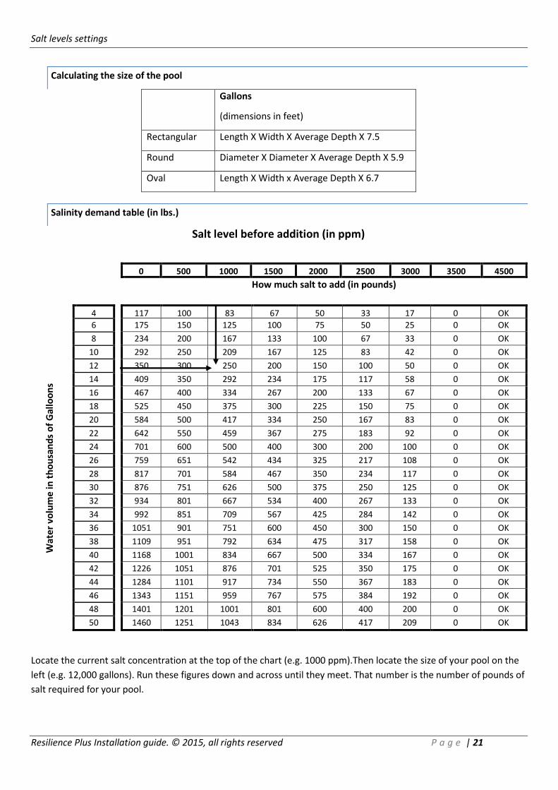
Calculating the size of the pool
Gallons
(dimensions in feet)
Rectangular Length X Width X Average Depth X 7.5
Round Diameter X Diameter X Average Depth X 5.9
Oval Length X Width x Average Depth X 6.7
Salinity demand table (in lbs.)
Salt level before addition (in ppm)
0 500 1000 1500 2000 2500 3000 3500 4500
How much salt to add (in pounds)
Wat
er
volu
me
in t
ho
usa
nd
s o
f G
allo
on
s
4 117 100 83 67 50 33 17 0 OK
6 175 150 125 100 75 50 25 0 OK
8 234 200 167 133 100 67 33 0 OK
10 292 250 209 167 125 83 42 0 OK
12 350 300 250 200 150 100 50 0 OK
14 409 350 292 234 175 117 58 0 OK
16 467 400 334 267 200 133 67 0 OK
18 525 450 375 300 225 150 75 0 OK
20 584 500 417 334 250 167 83 0 OK
22 642 550 459 367 275 183 92 0 OK
24 701 600 500 400 300 200 100 0 OK
26 759 651 542 434 325 217 108 0 OK
28 817 701 584 467 350 234 117 0 OK
30 876 751 626 500 375 250 125 0 OK
32 934 801 667 534 400 267 133 0 OK
34 992 851 709 567 425 284 142 0 OK
36 1051 901 751 600 450 300 150 0 OK
38 1109 951 792 634 475 317 158 0 OK
40 1168 1001 834 667 500 334 167 0 OK
42 1226 1051 876 701 525 350 175 0 OK
44 1284 1101 917 734 550 367 183 0 OK
46 1343 1151 959 767 575 384 192 0 OK
48 1401 1201 1001 801 600 400 200 0 OK
50 1460 1251 1043 834 626 417 209 0 OK
Locate the current salt concentration at the top of the chart (e.g. 1000 ppm).Then locate the size of your pool on the
left (e.g. 12,000 gallons). Run these figures down and across until they meet. That number is the number of pounds of
salt required for your pool.

replacing the preistaltic tube of the ph clear
Resilience Plus Installation guide. © 2015, all rights reserved P a g e | 22
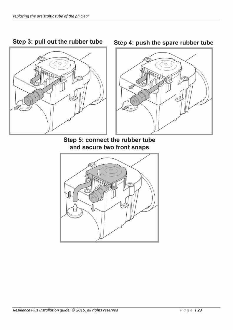
REPLACING THE PREISTALTIC TUBE OF THE PH CLEAR
It is recommended to replace the peristaltic tubing of your pH Clear dosing acid pump before starting a new bathing
season and/or every six months during the season. Please contact your local dealer to obtain a new tube.
WARNING: In order to perform this operation, you MUST wear rubber or polyethylene protective gloves
and safety glasses. It is also advisable to protect your clothes or wear dispensable ones.
1. Remove transparent protective outer cover.
2. Release the two front snaps of the small inner cover (leave the upper snap closed (see step 1).
3. Carefully slip off the rubber tube from the white check valve and then pull out the tube, holding it by the blue
connector (see steps 2 and 3). It is advisable to flush the pump with running tap water in order to dilute any
remaining acid which may have spilled from the tube.
4. Switch your control box to manual mode and start operating the pump. It should turn in anti-clockwise
direction.
5. Take the spare tube, which should be lightly lubricated with silicone grease, and slowly push it into the right
opening of the pH Clear dosing acid pump. The tube will slowly move inwards and the other end will come
out of the opposite slot (see step 4).
6. Once the tube is fully inserted, insert the blue connector into its slot in the casing (see step 5).
7. Then, push the other end of the tube onto the check valve nipple (see step 5).
8. Secure the two front snaps.
9. Fasten the inlet tube coming from the acid container to the blue connector. Beware of the acid which may still
adhere to this tube.
10. After replacing the new peristaltic tubing, leave the pump running in manual mode for 10-20 minutes in order
to release the air in the system.
11. This priming will insert some acid into your cell. In order to release the concentrated acid, run the pool pump
for approximately one hour or more.
replacing the preistaltic tube of the ph clear
Resilience Plus Installation guide. © 2015, all rights reserved P a g e | 23
understanding the chemistry
Resilience Plus Installation guide. © 2015, all rights reserved P a g e | 24
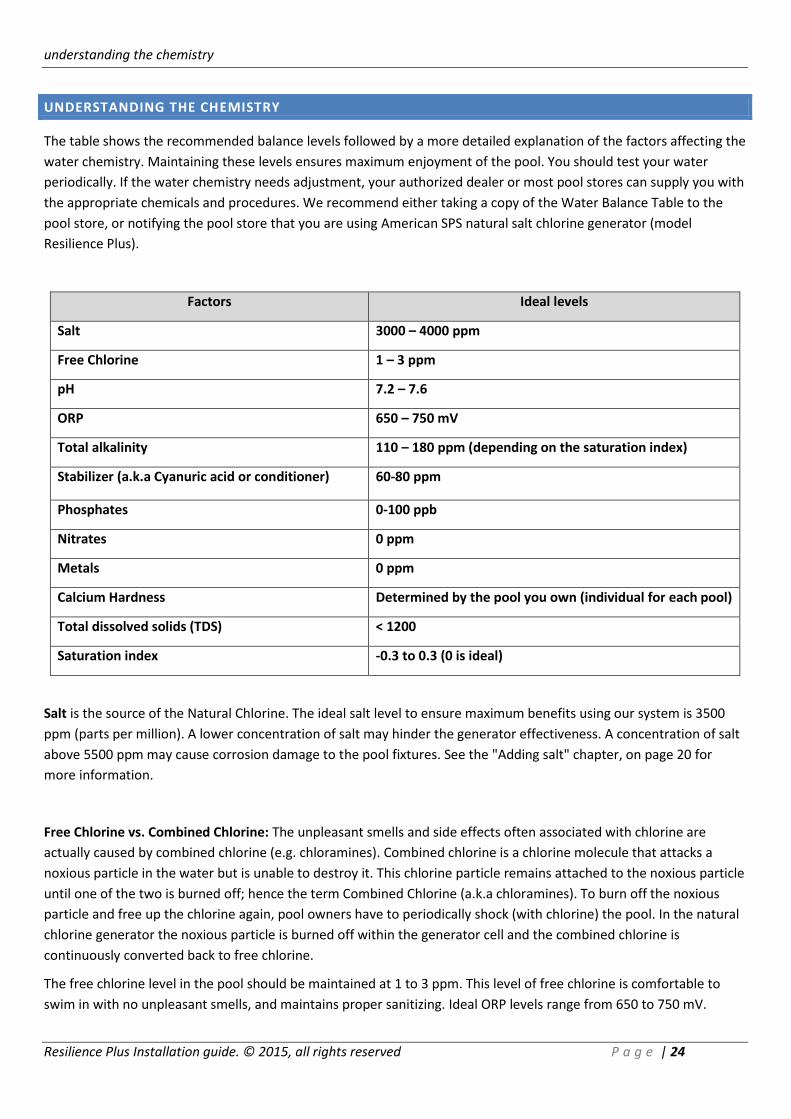
UNDERSTANDING THE CHEMISTRY
The table shows the recommended balance levels followed by a more detailed explanation of the factors affecting the
water chemistry. Maintaining these levels ensures maximum enjoyment of the pool. You should test your water
periodically. If the water chemistry needs adjustment, your authorized dealer or most pool stores can supply you with
the appropriate chemicals and procedures. We recommend either taking a copy of the Water Balance Table to the
pool store, or notifying the pool store that you are using American SPS natural salt chlorine generator (model
Resilience Plus).
Factors Ideal levels
Salt 3000 – 4000 ppm
Free Chlorine 1 – 3 ppm
pH 7.2 – 7.6
ORP 650 – 750 mV
Total alkalinity 110 – 180 ppm (depending on the saturation index)
Stabilizer (a.k.a Cyanuric acid or conditioner) 60-80 ppm
Phosphates 0-100 ppb
Nitrates 0 ppm
Metals 0 ppm
Calcium Hardness Determined by the pool you own (individual for each pool)
Total dissolved solids (TDS) < 1200
Saturation index -0.3 to 0.3 (0 is ideal)
Salt is the source of the Natural Chlorine. The ideal salt level to ensure maximum benefits using our system is 3500
ppm (parts per million). A lower concentration of salt may hinder the generator effectiveness. A concentration of salt
above 5500 ppm may cause corrosion damage to the pool fixtures. See the "Adding salt" chapter, on page 20 for
more information.
Free Chlorine vs. Combined Chlorine: The unpleasant smells and side effects often associated with chlorine are
actually caused by combined chlorine (e.g. chloramines). Combined chlorine is a chlorine molecule that attacks a
noxious particle in the water but is unable to destroy it. This chlorine particle remains attached to the noxious particle
until one of the two is burned off; hence the term Combined Chlorine (a.k.a chloramines). To burn off the noxious
particle and free up the chlorine again, pool owners have to periodically shock (with chlorine) the pool. In the natural
chlorine generator the noxious particle is burned off within the generator cell and the combined chlorine is
continuously converted back to free chlorine.
The free chlorine level in the pool should be maintained at 1 to 3 ppm. This level of free chlorine is comfortable to
swim in with no unpleasant smells, and maintains proper sanitizing. Ideal ORP levels range from 650 to 750 mV.

understanding the chemistry
Resilience Plus Installation guide. © 2015, all rights reserved P a g e | 25
pH is a measure of the acidic or basic solution. A scale of 0 to 14 is used to measure pH. Pure water has a pH of seven
(neutral), acid solution have a pH of less than seven, and basic (alkali) solutions have a pH of more than seven. The
recommended range is 7.2 to 7.6; chlorine is much more effective within this range and the water is most
comfortable for bathers. pH levels above 7.8 drastically reduce the effectiveness of the chlorine.
To lower the pH, add muriatic acid or dry acid. Be sure to read and follow the respective manufacturer's instructions.
Total Alkalinity mitigates changes in pH. It is often referred to as the "big brother of pH". Keeping proper levels of
total alkalinity helps reduce unwanted fluctuations in pH levels. Total alkalinity is also used to offset high or low levels
of calcium hardness.
Add muriatic acid or dry acid to lower the total alkalinity and sodium bicarbonate to raid the total alkalinity. Be sure
to read and follow the respective manufacturers' instructions.
Stabilizers (Cyanuric Acid or Conditioner) is necessary in most outdoor pools to maintain appropriate levels of
chlorine. Chlorine stabilizer helps provide an appropriate residual chlorine level in the water. Without stabilizer, UV
radiation from the sun will destroy most chlorine within 2 hours, but excessive amounts of stabilizer can decrease the
effectiveness of chlorine. Chlorine stabilizers should be maintained at 60 ppm to offset the harmful effect of the sun
while maintaining the effectiveness of the chlorine. Where pH/ORP automatic sensors are used, 40 ppm of stabilizer
suffices.
Phosphates and Nitrates set very high demands on chlorine; most nitrates and phosphates often bring the chlorine
level down to zero (0). You can have your water tested for nitrates and phosphates by a local professional. Your pool
should NOT contain Nitrates or Phosphates. To reduce Phosphate levels, use a phosphate remover from your local
pool professional. To reduce Nitrate levels, the pool must be partially or fully drained. Please check with your local
professional prior to draining the pool.
Metals can cause loss of chlorine and can stain your pool. If a water test reveals the presence of metals, refer to your
local pool professional for recommended methods of removal. Be sure to use a phosphate-free metal remover to
avoid replacing a metal problem with a phosphate problem.
Calcium Hardness, like pH and alkalinity, affects the water tendency to be aggressive or scale forming. Lower levels of
calcium hardness improve the chorine generators' ability to stay clean and provide softer silkier water for the
swimmers. Check with your local pool professional for proper calcium levels for your pool surface.
Total Dissolved Solids (TDS) is a measure of many types of dissolved materials, including salt. High effective TDS
levels (e.g. 1500 ppm and up) cause cloudy water and significantly increase chlorine demand.
To obtain the effective TDS level in a pool using a salt system, subtract the salt level from the TDS reading (e.g. 5000
TDS – 4000 salt = 1000 effective TDS).
Saturation Index determines whether the pool water is balanced, aggressive, or scale forming by comprehensively
taking into account all the relevant factors, including pH level, alkalinity level, calcium hardness, and temperature.
These factors should be periodically tested, then included into the worksheet on the following page to verify the
proper balance of the pool and make adjustments as necessary.
General troubleshooting
Resilience Plus Installation guide. © 2015, all rights reserved P a g e | 26
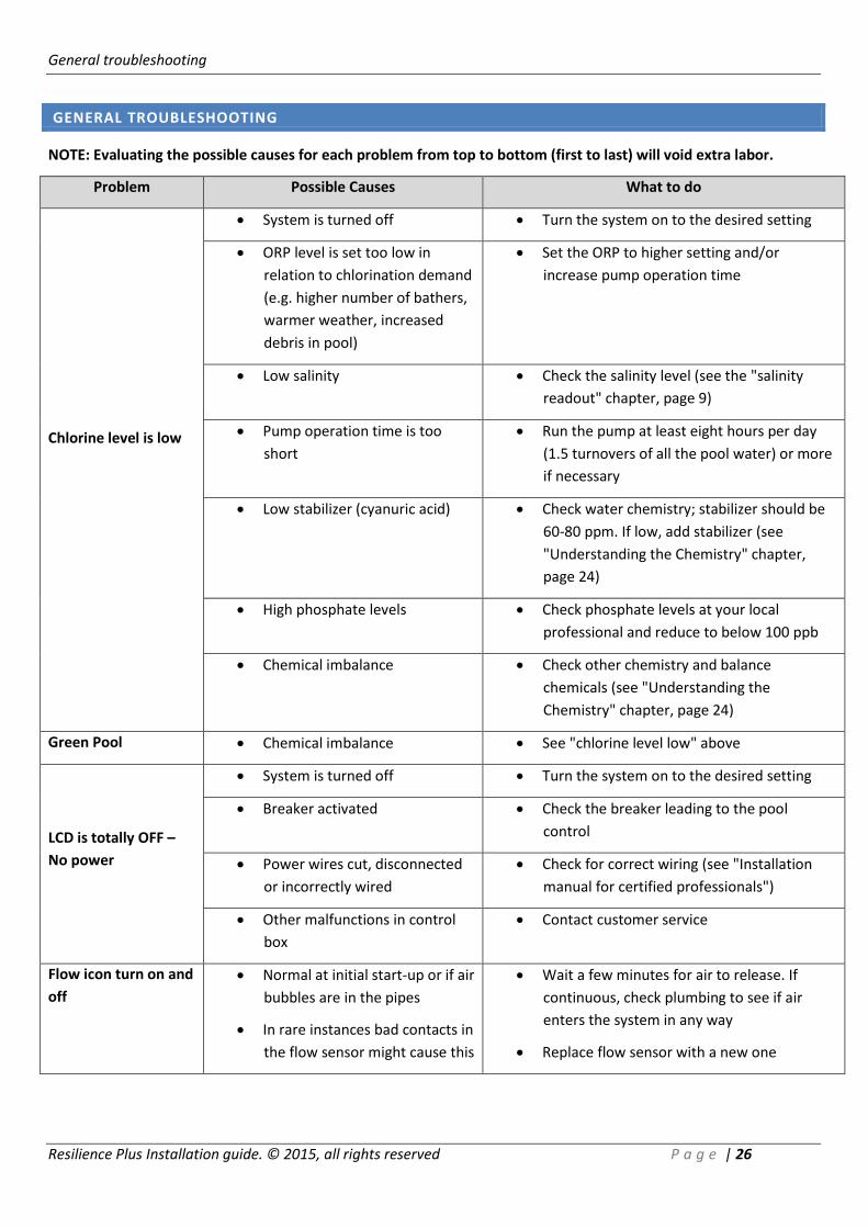
GENERAL TROUBLESHOOTING
NOTE: Evaluating the possible causes for each problem from top to bottom (first to last) will void extra labor.
Problem Possible Causes What to do
Chlorine level is low
System is turned off Turn the system on to the desired setting
ORP level is set too low in
relation to chlorination demand
(e.g. higher number of bathers,
warmer weather, increased
debris in pool)
Set the ORP to higher setting and/or
increase pump operation time
Low salinity Check the salinity level (see the "salinity
readout" chapter, page 9)
Pump operation time is too
short
Run the pump at least eight hours per day
(1.5 turnovers of all the pool water) or more
if necessary
Low stabilizer (cyanuric acid) Check water chemistry; stabilizer should be
60-80 ppm. If low, add stabilizer (see
"Understanding the Chemistry" chapter,
page 24)
High phosphate levels Check phosphate levels at your local
professional and reduce to below 100 ppb
Chemical imbalance Check other chemistry and balance
chemicals (see "Understanding the
Chemistry" chapter, page 24)
Green Pool Chemical imbalance See "chlorine level low" above
LCD is totally OFF –
No power
System is turned off Turn the system on to the desired setting
Breaker activated Check the breaker leading to the pool
control
Power wires cut, disconnected
or incorrectly wired
Check for correct wiring (see "Installation
manual for certified professionals")
Other malfunctions in control
box
Contact customer service
Flow icon turn on and
off
Normal at initial start-up or if air
bubbles are in the pipes
In rare instances bad contacts in
the flow sensor might cause this
Wait a few minutes for air to release. If
continuous, check plumbing to see if air
enters the system in any way
Replace flow sensor with a new one

General troubleshooting
Resilience Plus Installation guide. © 2015, all rights reserved P a g e | 27
Problem Possible Causes What to do
Flow icon is on and NO
FLOW message appears
in the numerical display
Insufficient water flow
from pump to flow
sensor and cell
This is normal if there is air in the lines or for a few
minutes at initial startup
Clean filters and strainers
Check for closed valves, pump cavitation, faulty
pump etc'
Obstruction or lime-
scale build up in cell
Clean cell according to instruction manual (see
"maintenance" chapter, page 17)
Flow sensor was not
installed in the correct
direction
Turn flow sensor so arrow faces direction of water
flow
Flow sensor is not fully
threaded into the Tee
connector
Fully thread the Flow sensor into the Tee
connector. Be careful not to damage the wires or
sensors.
Cut wires or insufficient
wire connections
Check the connection to ensure proper wire
contact
Output bar lights but
does not reach 100%
Output bar set too low Push the button to set the output level to a
higher setting
Dirty cell Check the cell to ensure that the blades are in good
condition and not coated with calcium buildup.
Cleaning the cell is recommended if it is calcified or
if the readout seems questionable. See "cell
cleaning" in the "maintenance" chapter, page 17
Poor connection of
quick connectors
Check for debris inside the connectors. Ensure that
the quick connectors are connected
Low pool water
temperature
In cold water (lower than 80 ºF the salt meter may
indicate a lower salinity level. This is normal
Not enough salt due to
heavy rain, initial
miscalculation etc'
Add salt to the pool. See :"Adding salt" chapter for
more information, page 20
It is recommended to periodically test the salt level
by a professional and adjust according to the
salinity demand table in this manual, page 21
Worn cell If none of the above resolves the problem the cell
may be worn out.
General troubleshooting
Resilience Plus Installation guide. © 2015, all rights reserved P a g e | 28
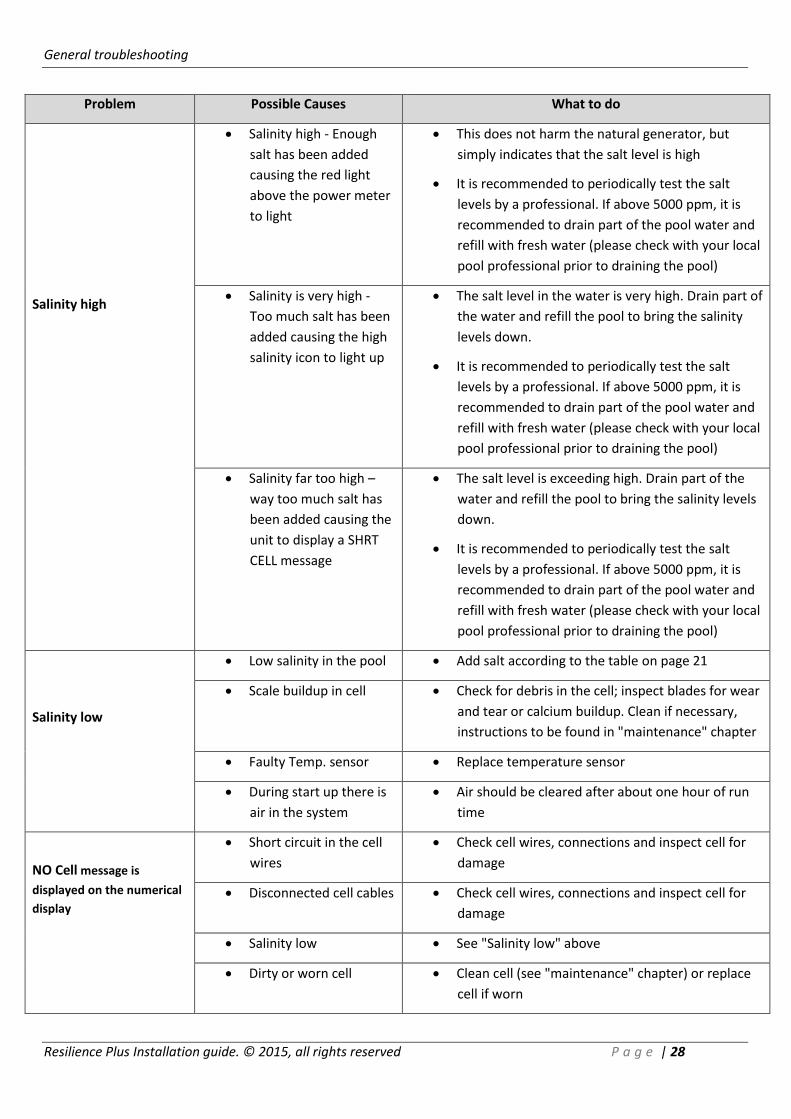
Problem Possible Causes What to do
Salinity high
Salinity high - Enough
salt has been added
causing the red light
above the power meter
to light
This does not harm the natural generator, but
simply indicates that the salt level is high
It is recommended to periodically test the salt
levels by a professional. If above 5000 ppm, it is
recommended to drain part of the pool water and
refill with fresh water (please check with your local
pool professional prior to draining the pool)
Salinity is very high -
Too much salt has been
added causing the high
salinity icon to light up
The salt level in the water is very high. Drain part of
the water and refill the pool to bring the salinity
levels down.
It is recommended to periodically test the salt
levels by a professional. If above 5000 ppm, it is
recommended to drain part of the pool water and
refill with fresh water (please check with your local
pool professional prior to draining the pool)
Salinity far too high –
way too much salt has
been added causing the
unit to display a SHRT
CELL message
The salt level is exceeding high. Drain part of the
water and refill the pool to bring the salinity levels
down.
It is recommended to periodically test the salt
levels by a professional. If above 5000 ppm, it is
recommended to drain part of the pool water and
refill with fresh water (please check with your local
pool professional prior to draining the pool)
Salinity low
Low salinity in the pool Add salt according to the table on page 21
Scale buildup in cell
Check for debris in the cell; inspect blades for wear
and tear or calcium buildup. Clean if necessary,
instructions to be found in "maintenance" chapter
Faulty Temp. sensor Replace temperature sensor
During start up there is
air in the system
Air should be cleared after about one hour of run
time
NO Cell message is
displayed on the numerical
display
Short circuit in the cell
wires
Check cell wires, connections and inspect cell for
damage
Disconnected cell cables Check cell wires, connections and inspect cell for
damage
Salinity low See "Salinity low" above
Dirty or worn cell Clean cell (see "maintenance" chapter) or replace
cell if worn
General troubleshooting
Resilience Plus Installation guide. © 2015, all rights reserved P a g e | 29
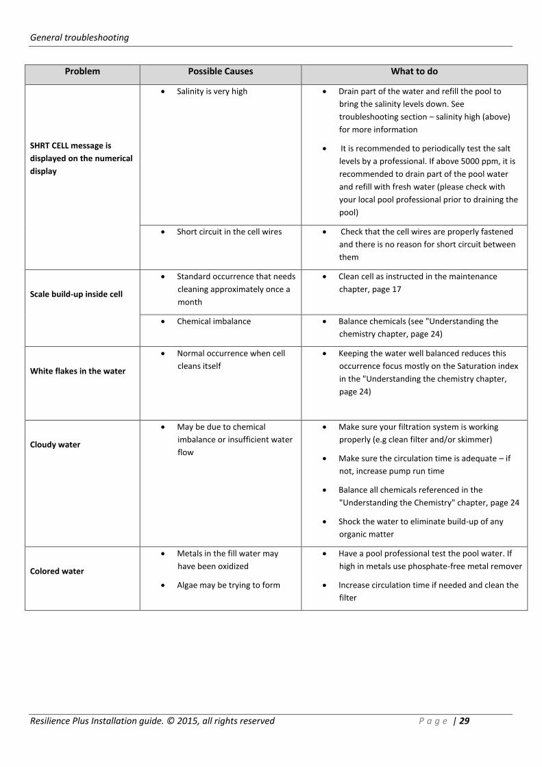
Problem Possible Causes What to do
SHRT CELL message is
displayed on the numerical
display
Salinity is very high Drain part of the water and refill the pool to
bring the salinity levels down. See
troubleshooting section – salinity high (above)
for more information
It is recommended to periodically test the salt
levels by a professional. If above 5000 ppm, it is
recommended to drain part of the pool water
and refill with fresh water (please check with
your local pool professional prior to draining the
pool)
Short circuit in the cell wires Check that the cell wires are properly fastened
and there is no reason for short circuit between
them
Scale build-up inside cell
Standard occurrence that needs
cleaning approximately once a
month
Clean cell as instructed in the maintenance
chapter, page 17
Chemical imbalance Balance chemicals (see "Understanding the
chemistry chapter, page 24)
White flakes in the water
Normal occurrence when cell
cleans itself
Keeping the water well balanced reduces this
occurrence focus mostly on the Saturation index
in the "Understanding the chemistry chapter,
page 24)
Cloudy water
May be due to chemical
imbalance or insufficient water
flow
Make sure your filtration system is working
properly (e.g clean filter and/or skimmer)
Make sure the circulation time is adequate – if
not, increase pump run time
Balance all chemicals referenced in the
"Understanding the Chemistry" chapter, page 24
Shock the water to eliminate build-up of any
organic matter
Colored water
Metals in the fill water may
have been oxidized
Algae may be trying to form
Have a pool professional test the pool water. If
high in metals use phosphate-free metal remover
Increase circulation time if needed and clean the
filter

Resilience plus troubleshooting
Resilience Plus Installation guide. © 2015, all rights reserved P a g e | 30
Problem Possible Causes What to do
Algae
May be due to low chlorine
levels or a chemical imbalance
Have the water tested for chemical balance
including pH, phosphates and nitrates
If chlorine level is low, see "Chlorine level low" in
this troubleshooting section
Use nonmetallic (polyquat) algaecide as
instructed on the bottle and brush the side of the
pool often
Clean the filter and shock the pool with chlorine
daily until the water clarity returns
RESILIENCE PLUS TROUBLESHOOTING
Problem Possible causes What to do
PH HIGH
pH set point is too high.
Check the set point and if required change it
Water chemistry is not
balanced
Manually check the pH in the water. If the
reading is identical to the manual result balance
waters' pH
Acid tank is empty Replace acid tank with a full one
pH clear acid pump is not
working properly
Check the pH clear pump by operating it
manually (see chapter "pH manual", page 13) if
the acid pump is not working check its
individual parts and replace if needed
pH sensor needs to be cleaned
and calibrated
Clean then calibrate the pH sensor as described
in "calibrating pH sensor", page 12
pH sensor is worn out and/or
faulty
Replace pH sensor
Sensor cable connection may
be reversed
Ensure that sensor cable is properly connected
to its respective connection on the controller
unit
Unit is functioning on default
mode
Make sure AUTO mode is working
Resilience plus troubleshooting
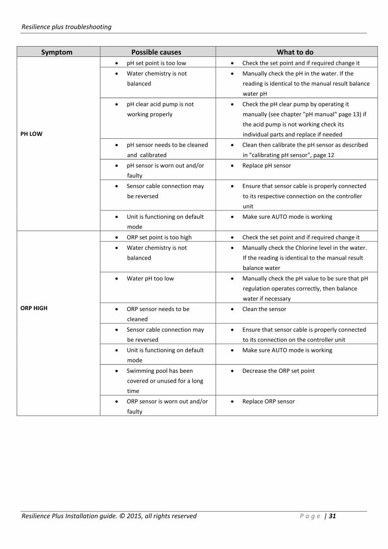
Resilience Plus Installation guide. © 2015, all rights reserved P a g e | 31
Symptom Possible causes What to do
PH LOW
pH set point is too low Check the set point and if required change it
Water chemistry is not
balanced
Manually check the pH in the water. If the
reading is identical to the manual result balance
water pH
pH clear acid pump is not
working properly
Check the pH clear pump by operating it
manually (see chapter "pH manual" page 13) if
the acid pump is not working check its
individual parts and replace if needed
pH sensor needs to be cleaned
and calibrated
Clean then calibrate the pH sensor as described
in "calibrating pH sensor", page 12
pH sensor is worn out and/or
faulty
Replace pH sensor
Sensor cable connection may
be reversed
Ensure that sensor cable is properly connected
to its respective connection on the controller
unit
Unit is functioning on default
mode
Make sure AUTO mode is working
ORP HIGH
ORP set point is too high Check the set point and if required change it
Water chemistry is not
balanced
Manually check the Chlorine level in the water.
If the reading is identical to the manual result
balance water
Water pH too low Manually check the pH value to be sure that pH
regulation operates correctly, then balance
water if necessary
ORP sensor needs to be
cleaned
Clean the sensor
Sensor cable connection may
be reversed
Ensure that sensor cable is properly connected
to its connection on the controller unit
Unit is functioning on default
mode
Make sure AUTO mode is working
Swimming pool has been
covered or unused for a long
time
Decrease the ORP set point
ORP sensor is worn out and/or
faulty
Replace ORP sensor
Resilience plus troubleshooting
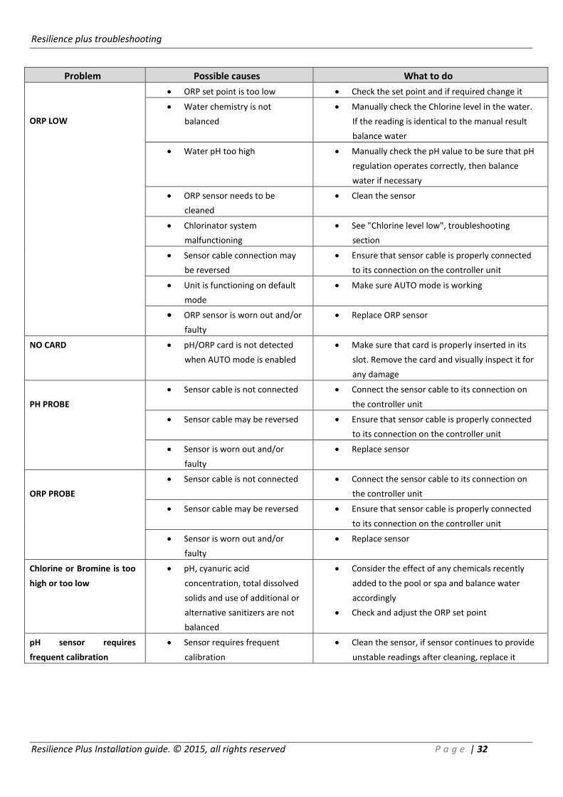
Resilience Plus Installation guide. © 2015, all rights reserved P a g e | 32
Problem Possible causes What to do
ORP LOW
ORP set point is too low Check the set point and if required change it
Water chemistry is not
balanced
Manually check the Chlorine level in the water.
If the reading is identical to the manual result
balance water
Water pH too high Manually check the pH value to be sure that pH
regulation operates correctly, then balance
water if necessary
ORP sensor needs to be
cleaned
Clean the sensor
Chlorinator system
malfunctioning
See "Chlorine level low", troubleshooting
section
Sensor cable connection may
be reversed
Ensure that sensor cable is properly connected
to its connection on the controller unit
Unit is functioning on default
mode
Make sure AUTO mode is working
ORP sensor is worn out and/or
faulty
Replace ORP sensor
NO CARD pH/ORP card is not detected
when AUTO mode is enabled
Make sure that card is properly inserted in its
slot. Remove the card and visually inspect it for
any damage
PH PROBE
Sensor cable is not connected Connect the sensor cable to its connection on
the controller unit
Sensor cable may be reversed Ensure that sensor cable is properly connected
to its connection on the controller unit
Sensor is worn out and/or
faulty
Replace sensor
ORP PROBE
Sensor cable is not connected Connect the sensor cable to its connection on
the controller unit
Sensor cable may be reversed Ensure that sensor cable is properly connected
to its connection on the controller unit
Sensor is worn out and/or
faulty
Replace sensor
Chlorine or Bromine is too
high or too low
pH, cyanuric acid
concentration, total dissolved
solids and use of additional or
alternative sanitizers are not
balanced
Consider the effect of any chemicals recently
added to the pool or spa and balance water
accordingly
Check and adjust the ORP set point
pH sensor requires
frequent calibration
Sensor requires frequent
calibration
Clean the sensor, if sensor continues to provide
unstable readings after cleaning, replace it

ph clear system troubleshooting
Resilience Plus Installation guide. © 2015, all rights reserved P a g e | 33
PH CLEAR SYSTEM TROUBLESHOOTING
WARNING! You are about to manipulate components which are in contact with concentrated Muriatic Acid.
USE PROTECTIVE GLOVES, GOGGLES and CLOTHING FOR YOUR SECURITY. In case of involuntary contact
with acid, flush the affected areas with running water. In case of contact with eyes, flush with water and
contact a physician!
Problem Possible Causes What to do
Scale build-up in cell
Automatic cell cleaning level
setting is too low
Adjust dosing LVL to a higher level (1 to 9)
Hydrochloric (Muriatic) Acid
container is empty
Replenish acid in container or replace
with a new container
After replacing the acid container, enter
manual mode and run the system for 1-2
sequences in order to release air
(priming)
Acid inlet tube is not in
contact with the acid (above
acid level)
Push the tube to the bottom of the acid
container. Observe the priming procedure
as described above
Pump does not run during
self-cleaning mode (manual
and automatic)
Check the electrical connection between
the pH Clear and the control box
Pump runs in the wrong
direction
Enter manual mode and check that the
pump runs in anti-clockwise direction if
not, call a technician
Peristaltic tubing is worn out
or ruptured
Replace ruptured tubing
IMPORTANT: follow the instructions listed
in the "Replacing the peristaltic tube
chapter", page 22
If there are no faults listed
above, the small check valve
may be obstructed
Carefully pull out the check valve from the
pipe system. Disconnect the peristaltic
tubing and replace with a new valve
discard old valve
pH level in pool is too
high
Automatic pH reducing units
setting is too low
Adjust dosing level to a higher level (1 to
50 units/week)

ph clear system troubleshooting
Resilience Plus Installation guide. © 2015, all rights reserved P a g e | 34
Problem Possible Causes What to do
pH level in the pools is
too high – no reaction to
a higher setting
Hydrochloric (Muriatic) acid
container is empty
Replenish acid in the container or replace
with a new one
After replacing acid container, enter
manual mode and run the system for 1-2
sequences in order to release air from the
system (priming)
Wrong acid is used Verify the you are using muriatic acid
(33% HCL)
Check that your acid is still active
Acid inlet tube is not in
contact with acid (above acid
level)
Push the tube to the bottom of the acid
container. Observe the priming procedure
as described above
Pump is not running during
"pH reducing mode"
(manual and automatic)
Check the electrical connection between
the pH Clear and the control box
Check whether the connector to the acid
pump is inserted properly
Pump runs in the wrong
direction
Enter manual mode and check that the
pump runs in anti-clockwise direction if
not, call a technician
Peristaltic tubing is worn out
or ruptured
Replace ruptured tubing
IMPORTANT: follow the instructions listed
in the "Replacing the peristaltic tube
chapter", page 22
If all of the above mentioned
are all right, the small check
valve may be obstructed
Carefully pull out the check valve from the
pipe system. Disconnect the peristaltic
tubing and replace with a new valve
discard old valve
pH level in pool is too
low (<7.1) – water
becomes acidic
Automatic pH reducing units
are set too high
Adjust/reduce the dosing level to a higher
level (1 to 50 units/week)
Check that you are using the correct acid
concentration (HCL 33%)