agitation and mixing of fluids
TRANSCRIPT
AGITATION AND MIXING OF
FLUIDS
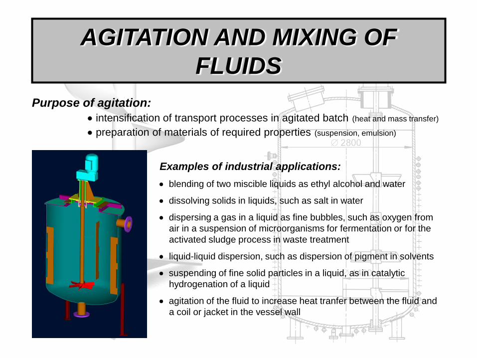
Purpose of agitation:
intensification of transport processes in agitated batch (heat and mass transfer)
preparation of materials of required properties (suspension, emulsion)
Examples of industrial applications:
blending of two miscible liquids as ethyl alcohol and water
dissolving solids in liquids, such as salt in water
dispersing a gas in a liquid as fine bubbles, such as oxygen from
air in a suspension of microorganisms for fermentation or for the
activated sludge process in waste treatment
liquid-liquid dispersion, such as dispersion of pigment in solvents
suspending of fine solid particles in a liquid, as in catalytic
hydrogenation of a liquid
agitation of the fluid to increase heat tranfer between the fluid and
a coil or jacket in the vessel wall
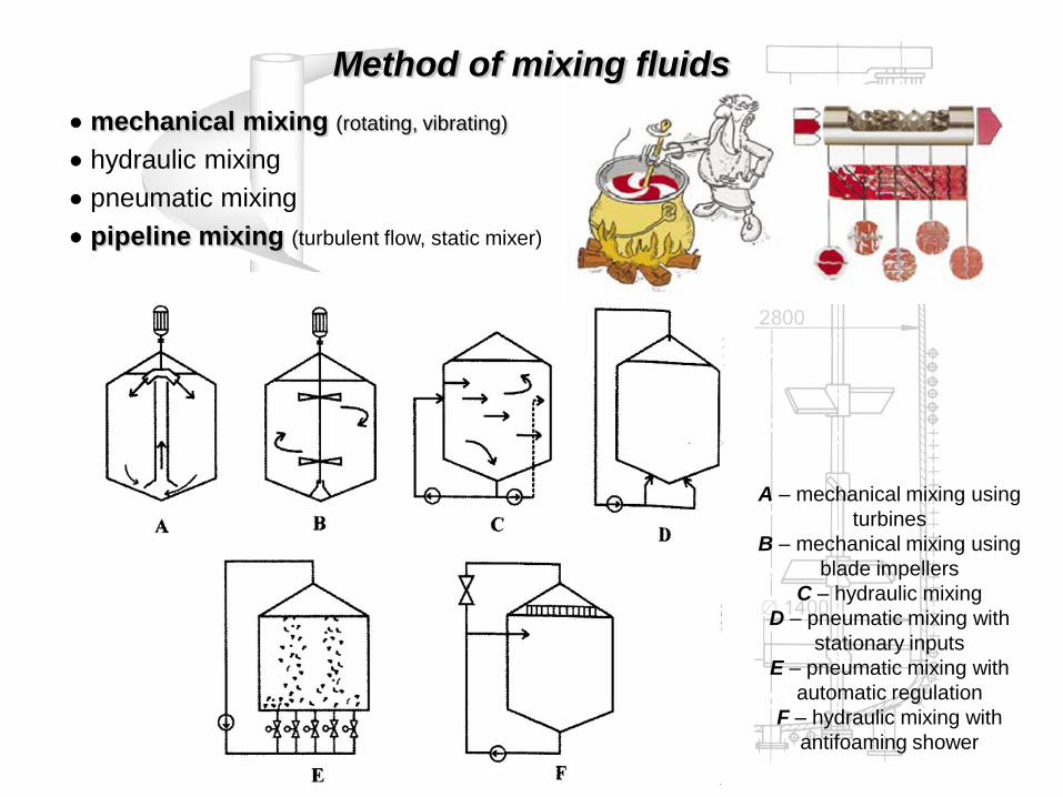
mechanical mixing (rotating, vibrating)
hydraulic mixing
pneumatic mixing
pipeline mixing (turbulent flow, static mixer)
Method of mixing fluids
A – mechanical mixing using
turbines
B – mechanical mixing using
blade impellers
C – hydraulic mixing
D – pneumatic mixing with
stationary inputs
E – pneumatic mixing with
automatic regulation
F – hydraulic mixing with
antifoaming shower
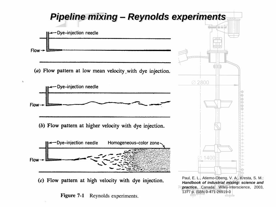
Pipeline mixing – Reynolds experiments
Paul, E. L., Atiemo-Obeng, V. A., Kresta, S. M.:
Handbook of industrial mixing: science and
practice. Canada: Wiley-Interscience, 2003,
1377 p. ISBN 0-471-26919-0

a – axial-flow pattern, baffled vessel, b – radial-flow pattern, baffled vessel,
c – tangential-flow pattern, unbaffled vessel
Flow in agitated batch

Equipment for mechanical mixing
Design layout of mixing equipments
A B C
A – Centrally placed impeller in bafled vessel, B – Side-entring propeller, C – Agitator with draught tube
A B
A – Equipment with a drive at the top, B – Equipment with a drive at the bottom
Mechanical seal

Close clearance agitator High-speed impeller
Design layout of agitators

Maine type of close clearance agitators
No. Layout of agitator Name T/d Geometrical parameters
1
Anchor (paddle)
agitator
CVS 69 1014
1,11
8,0/ dhv
12,0/ dh
055,0/2 dH
2
Helical-screw agitator
with draught tube
CVS 69 1028
2
5,1/ dhv
1/ ds
1,1/́ dD
15,1´/ DH
3
Eccentrically placed
helical-screw agitator 2
5,1/ dhv
25,0/2 dH
1/ ds
02,0/ Tc
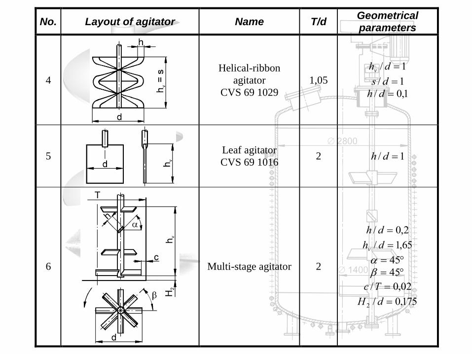
No. Layout of agitator Name T/d Geometrical parameters
4
Helical-ribbon
agitator
CVS 69 1029
1,05
1/ dhv
1/ ds
1,0/ dh
5
Leaf agitator
CVS 69 1016 2 1/ dh
6
Multi-stage agitator 2
2,0/ dh
65,1/ dhv
45
45
02,0/ Tc
175,0/2 dH
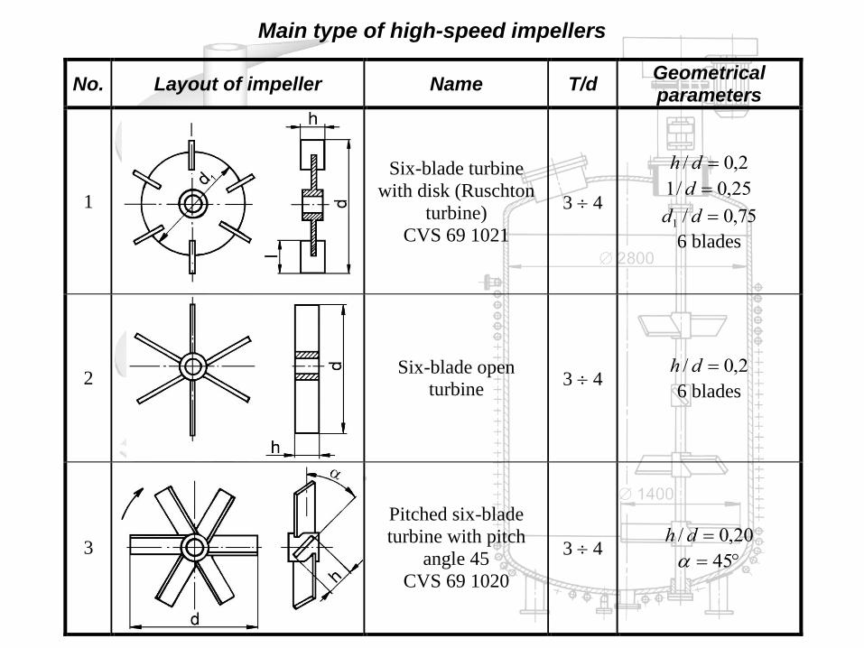
Main type of high-speed impellers
No. Layout of impeller Name T/d Geometrical parameters
1
Six-blade turbine
with disk (Ruschton
turbine)
CVS 69 1021
3 4
2,0/ dh
25,0/1 d
75,0/1 dd
6 blades
2
Six-blade open
turbine 3 4
2,0/ dh
6 blades
3
Pitched six-blade
turbine with pitch
angle 45
CVS 69 1020
3 4 20,0/ dh
45

No. Layout of impeller Name T/d Geometrical parameters
4
Pitched three-blade
turbine with pitch
angle 45°
CVS 69 1025.3
3 4 2,0/ dh
45
5
Propeller
CVS 69 1019 3 4
1/ ds
22,0/ dh
4,0/ dR
16,0/1 RR
6
High shear stress
impeller
CVS 69 1038.1, .2 2 4
1st variant
1,0/ dh
8,0/2 dd
2nd
variant
075,0/ dh
85,0/2 dd
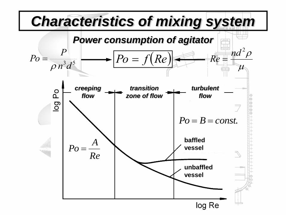
Power consumption of agitator
Characteristics of mixing system
RefPo 53dn
PPo
2ndRe
Re
APo
creeping
flow
turbulent
flow
transition
zone of flow
baffled
vessel
unbaffled
vessel
.constBPo
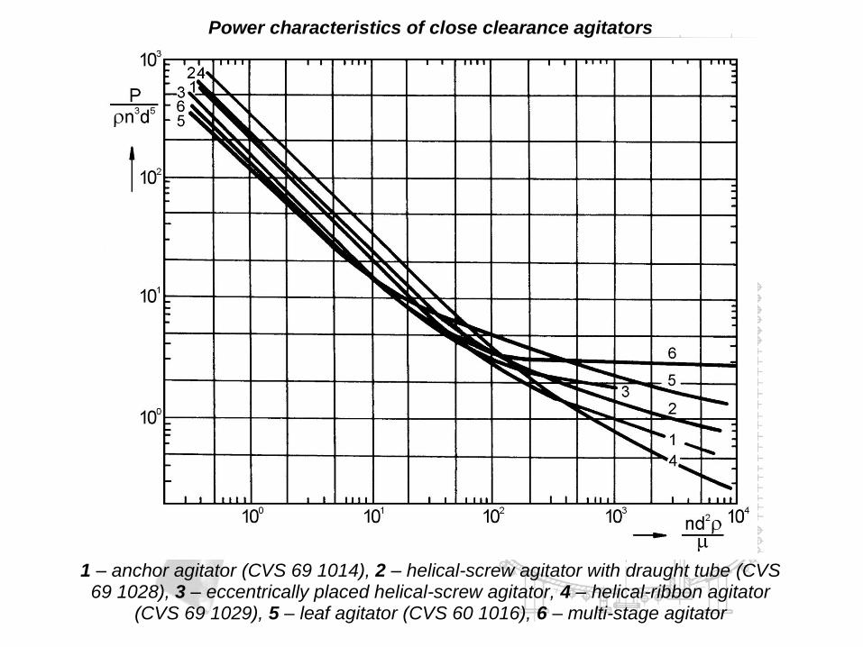
Power characteristics of close clearance agitators
1 – anchor agitator (CVS 69 1014), 2 – helical-screw agitator with draught tube (CVS
69 1028), 3 – eccentrically placed helical-screw agitator, 4 – helical-ribbon agitator (CVS 69 1029), 5 – leaf agitator (CVS 60 1016), 6 – multi-stage agitator

Power characteristics of high-speed impellers operated in baffled vessel
1 – six-blade turbine with disk (Ruschton turbine) (CVS 69 1021), 2 – six-blade open turbine, 3 – pitched six-blade turbine with pitch angle 45 (CVS 69 1020),
4 – Pitched three-blade turbine with pitch angle 45° (CVS 69 1025.3), 5 – propeller (CVS 60 1019), 6a,b – high shear stress impeller (CVS 69 1038.1.2)
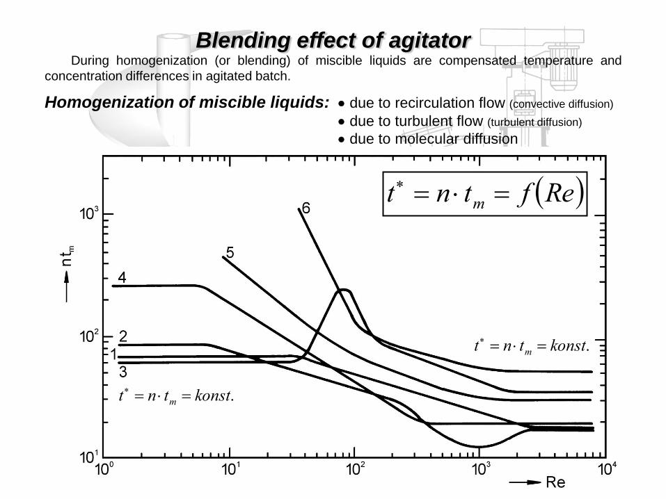
Blending effect of agitator
Homogenization of miscible liquids: due to recirculation flow (convective diffusion)
due to turbulent flow (turbulent diffusion)
due to molecular diffusion
Reftnt m
.konsttnt m
.konsttnt m
During homogenization (or blending) of miscible liquids are compensated temperature and
concentration differences in agitated batch.
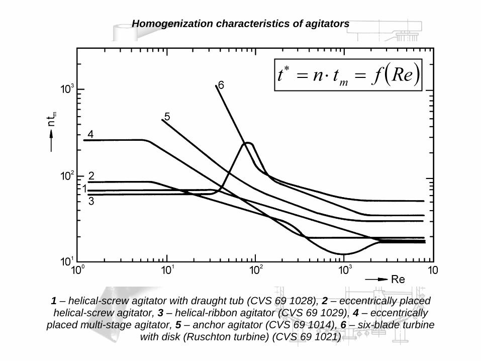
Homogenization characteristics of agitators
1 – helical-screw agitator with draught tub (CVS 69 1028), 2 – eccentrically placed helical-screw agitator, 3 – helical-ribbon agitator (CVS 69 1029), 4 – eccentrically
placed multi-stage agitator, 5 – anchor agitator (CVS 69 1014), 6 – six-blade turbine with disk (Ruschton turbine) (CVS 69 1021)
Reftnt m

1 – šroubové míchadlo (CVS 69 1028), 2 – šroubové míchadlo umístěné excentricky, 3 – pásové míchadlo (CVS 69 1029), 4 – čtyřnásobné lopatkové míchadlo umístěné excentricky, 5 – kotvové míchadlo (CVS 69 1014), 6 – turbínové míchadlo (CVS 69 1021), 7 – šestilopatkové míchadlo (CVS 69 1020), 8 – třílopatkové míchadlo (CVS
69 1025.3)
mtPE
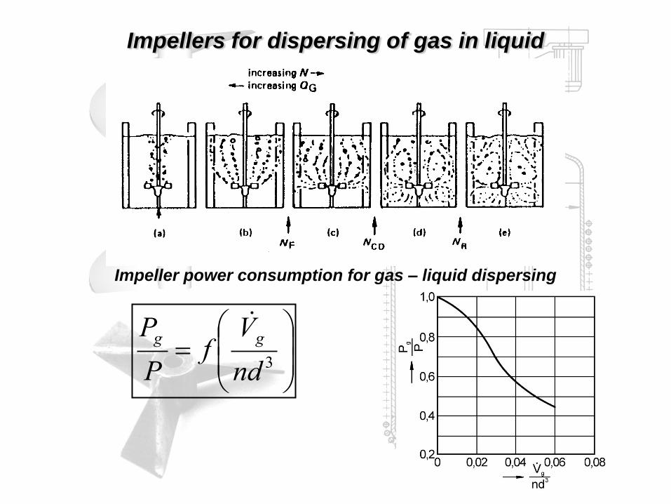
Impellers for dispersing of gas in liquid
Impeller power consumption for gas – liquid dispersing
3nd
Vf
P
P gg

Mixing of suspension
Impeller power consumption for mixing of suspension
RefPo 53dn
PPo
su
sundRe
2
lvsvsu cc 1

Just-suspended impeller speed
0,1
1
10
0,0001 0,001 0,01 0,1
D/T
Fr'
0,025
0,05
0,1
0,15
0,2
cv
c
T
DCrF
g
dnrF
2
vcBAC exp
vcc

EXAMPLE: Blending efficiency of impellers
Select type of high-speed impeller with minimum energetic requirements
for continual blending (homogenization) of two miscible liquids A + B ( = 5
mPa·s, = 1100 kg·m-3) with flow rate of mixture 10 l·s-1. For suitable degree
of homogenization must be residence time of liquids in equipment 5 x longer
than blending time. Mixing equipment has standard geometrical configuration
(baffled cylindrical vessel with diameter T = 1200 mm, T/d = 3.3; H2/d = 1, H/T
= 1 ).
Dimensionless blending time of high-speed impellers in turbulent flow regime
Type of impeller T/d H2/d n·tm
Six-blade turbine with disk (Ruschton
turbine), CVS 69 1021 3.3 1 51.8
Pitched six-blade turbine with pitch
angle 45, CVS 69 1020 3.3 1 53.1
Pitched three-blade turbine with pitch
angle 45°, CVS 69 1025.3 3.3 1 60.5