agilent e4405b specifications and characteristics type lin ±(0.5% of span + 2 × ) sweep type log...
TRANSCRIPT

173
Agilent E4405B
Specifications and C
haracteristics
3 Agilent E4405B Specifications and Characteristics
174 Chapter 3
Agilent E4405B Specifications and CharacteristicsAbout This Chapter
Agi
lent
E44
05B
Spe
cific
atio
ns a
nd
Cha
ract
eris
tics
About This ChapterThis chapter contains specifications and characteristics for the Agilent E4405B spectrum analyzer. The distinction between specifications and characteristics is described as follows.
• Specifications describe the performance of parameters covered by the product warranty. (The temperature range is 0 °C to 55 °C, unless otherwise noted.)
• Characteristics describe product performance that is useful in the application of the product, but is not covered by the product warranty.
• Typical performance describes additional product performance information that is not covered by the product warranty. It is performance beyond specification that 80% of the units exhibit with a 95% confidence level over the temperature range 20 to 30 °C. Typical performance does not include measurement uncertainty.
• Nominal values indicate the expected performance, or describe product performance that is useful in the application of the product, but is not covered by the product warranty.
The following conditions must be met for the analyzer to meet its specifications.
o The analyzer is within the one year calibration cycle.
o If Auto Align All is selected:
— After 2 hours of storage within the operating temperature range.
— 5 minutes after the analyzer is turned on with sweep times less than 4 seconds.
— After the front-panel amplitude reference is connected to the INPUT, and Align Now RF has been run, after the analyzer is turned on. And, once every 24 hours, or if ambient temperature changes more than 30 °C1.
o If Auto Align Off is selected:
— When the analyzer is at a constant temperature, within the operating temperature range, for a minimum of 90 minutes.
— After the analyzer is turned on for a minimum of 90 minutes, the front panel amplitude reference has been connected to the INPUT, and Align Now All has been run.
1. 10 °C if Preamp (Option 1DS) is active.
Chapter 3 175
Agilent E4405B Specifications and CharacteristicsAbout This Chapter
Agilent E4405B
Specifications and C
haracteristics
— When Align Now All is run:
• Every hour
• If the ambient temperature changes more than 3 °C
• If the 10 MHz reference changes
— When Align Now RF is run (with the front-panel amplitude reference connected to the INPUT):
• Every 24 hours
• If the ambient temperature changes more than 30 °C1
o If Auto Align All but RF is selected:
— When the analyzer is at a constant temperature, within the operating temperature range, for a minimum of 90 minutes.
— After the analyzer is turned on for a minimum of 90 minutes, the front panel amplitude reference has been connected to the INPUT, and Align Now RF has been run.
— When Align Now RF is run (with the front-panel amplitude reference connected to the INPUT):
• Every hour
• If the ambient temperature changes more than 3 °C
1. 10 °C if Preamp (Option 1DS) is active.
176 Chapter 3
Agilent E4405B Specifications and CharacteristicsFrequency
Agi
lent
E44
05B
Spe
cific
atio
ns a
nd
Cha
ract
eris
tics
Frequency
Specifications Supplemental Information
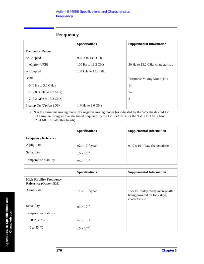
Frequency Range
dc Coupled 9 kHz to 13.2 GHz
(Option UKB) 100 Hz to 13.2 GHz 30 Hz to 13.2 GHz, characteristic
ac Coupled 100 kHz to 13.2 GHz
Band Harmonic Mixing Mode (Na)
a. N is the harmonic mixing mode. For negative mixing modes (as indicated by the “–”), the desired 1st LO harmonic is higher than the tuned frequency by the 1st IF (3.9214 for the 9 kHz to 3 GHz band, 321.4 MHz for all other bands).
0 (0 Hz to 3.0 GHz) 1–
1 (2.85 GHz to 6.7 GHz) 1–
2 (6.2 GHz to 13.2 GHz) 2–
Preamp On (Option 1DS) 1 MHz to 3.0 GHz
Specifications Supplemental Information
Frequency Reference
Aging Rate ±2 × 10⁻⁶/year ±1.0 × 10⁻⁷/day, characteristic
Settability ±5 × 10⁻⁷
Temperature Stability ±5 × 10⁻⁶
Specifications Supplemental Information
High Stability Frequency Reference (Option 1D5)
Aging Rate ±1 × 10⁻⁷/year ±5 × 10⁻¹⁰/day, 7-day average after being powered on for 7 days, characteristic
Settability ±1 × 10⁻⁸
Temperature Stability
20 to 30 °C ±1 × 10⁻⁸
0 to 55 °C ±5 × 10⁻⁸

Chapter 3 177
Agilent E4405B Specifications and CharacteristicsFrequency
Agilent E4405B
Specifications and C
haracteristics
Warm-up (Internal frequencyreference selected)
After 5 minutes
After 15 minutes
< ±1 × 10⁻⁷ of final frequency,a characteristic
< ±1 × 10⁻⁸ of final frequency,a characteristic
a. Final frequency is defined as frequency 60 minutes after power-on with analyzer set to internal fre-quency reference.
Specifications Supplemental Information
Frequency Readout Accuracy
(Start, Stop, Center, Marker) ±((frequency indication × frequency reference errora)
+ 0.5% of span
+
+ 15% of RBW + 10 Hz + 1 Hz × Nb)
a. Frequency reference error = (aging rate × period of time since adjustment + settability + temperature stability).
b. N is the harmonic mixing mode.
Specifications Supplemental Information
Marker Frequency Counter
Resolution Selectable from 1 Hz to 100 kHz
Accuracya ±(marker frequency × frequency reference errorb + counter resolution)c
For RBW ≥ 1 kHz
a. Marker level to displayed noise level > 25 dB, RBW/ Span ≥ 0.002, frequency offset = 0 Hz. b. Frequency reference error = (aging rate × period of time since adjustment + settability + temperature
stability).c. For firmware revisions prior to A.03.00, add 1 Hz x N, where N is the harmonic mixing mode.
Specifications Supplemental Information
Frequency Span
Range 0 Hz (zero span), 100 Hz to 13.2 GHz
Resolution 2 Hz x Na
Accuracyb
Specifications Supplemental Information
spansweep points 1–----------------------------------------
178 Chapter 3
Agilent E4405B Specifications and CharacteristicsFrequency
Agi
lent
E44
05B
Spe
cific
atio
ns a
nd
Cha
ract
eris
tics
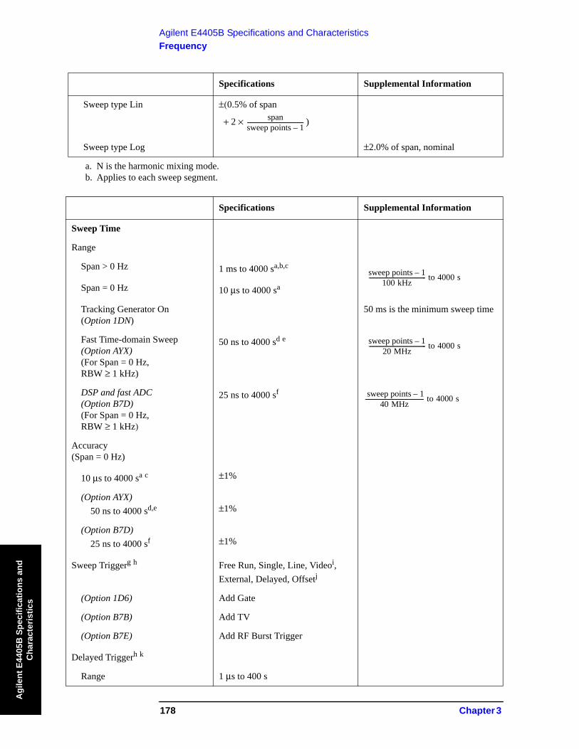
Sweep type Lin ±(0.5% of span
+ 2 × )
Sweep type Log ±2.0% of span, nominal
a. N is the harmonic mixing mode.b. Applies to each sweep segment.
Specifications Supplemental Information
Sweep Time
Range
Span > 0 Hz 1 ms to 4000 sa,b,c
Span = 0 Hz 10 μs to 4000 sa
Tracking Generator On(Option 1DN)
50 ms is the minimum sweep time
Fast Time-domain Sweep (Option AYX) (For Span = 0 Hz,RBW ≥ 1 kHz)
50 ns to 4000 sd e
DSP and fast ADC(Option B7D) (For Span = 0 Hz,RBW ≥ 1 kHz)
25 ns to 4000 sf
Accuracy(Span = 0 Hz)
10 μs to 4000 sa c ±1%
(Option AYX)50 ns to 4000 sd,e ±1%
(Option B7D)25 ns to 4000 sf ±1%
Sweep Triggerg h Free Run, Single, Line, Videoi, External, Delayed, Offsetj
(Option 1D6) Add Gate
(Option B7B) Add TV
(Option B7E) Add RF Burst Trigger
Delayed Triggerh k
Range 1 μs to 400 s
Specifications Supplemental Information
spansweep points 1–----------------------------------------
sweep points 1–100 kHz---------------------------------------- to 4000 s
sweep points 1–20 MHz---------------------------------------- to 4000 s
sweep points 1–40 MHz----------------------------------------- to 4000 s
Chapter 3 179
Agilent E4405B Specifications and CharacteristicsFrequency
Agilent E4405B
Specifications and C
haracteristics
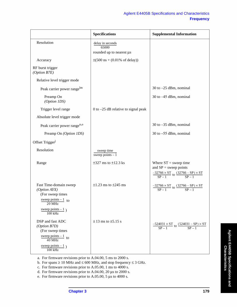
Resolution
rounded up to nearest μs
Accuracy ±(500 ns + (0.01% of delay))
RF burst trigger(Option B7E)
Relative level trigger mode
Peak carrier power rangelm 30 to –25 dBm, nominal
Preamp On(Option 1DS)
30 to –45 dBm, nominal
Trigger level range 0 to –25 dB relative to signal peak
Absolute level trigger mode
Peak carrier power rangen,o 30 to –35 dBm, nominal
Preamp On (Option 1DS) 30 to –55 dBm, nominal
Offset Triggerj
Resolution
Range ±327 ms to ±12.3 ks Where ST = sweep timeand SP = sweep points
Fast Time-domain sweep(Option AYX)
(For sweep times to
)
±1.23 ms to ±245 ms
DSP and fast ADC(Option B7D)
(For sweep times
to
)
± 13 ms to ±5.15 s
a. For firmware revisions prior to A.04.00, 5 ms to 2000 s.b. For spans ≥ 10 MHz and ≤ 600 MHz, and stop frequency ≤ 3 GHz.c. For firmware revisions prior to A.05.00, 1 ms to 4000 s.d. For firmware revisions prior to A.04.00, 20 μs to 2000 s.e. For firmware revisions prior to A.05.00, 5 μs to 4000 s.
Specifications Supplemental Information
delay in seconds65000---------------------------------------
sweep timesweep points 1–----------------------------------------
32766 ST×–SP 1–------------------------------- to 32766 SP–( ) ST×
SP 1–---------------------------------------------
sweep points 1–20 MHz----------------------------------------
sweep points 1–100 kHz----------------------------------------
32766 ST×–SP 1–------------------------------- to 32766 SP–( ) ST×
SP 1–---------------------------------------------
sweep points 1–40 MHz----------------------------------------
sweep points 1–100 kHz
----------------------------------------
524031 ST×–SP 1–---------------------------------- to 524031 SP–( ) ST×
SP 1–------------------------------------------------

180 Chapter 3
Agilent E4405B Specifications and CharacteristicsFrequency
Agi
lent
E44
05B
Spe
cific
atio
ns a
nd
Cha
ract
eris
tics
f. For firmware revisions prior to A.05.00, 2.5 μs to 4000 s.g. Gate cannot be used simultaneously with delayed or TV trigger (Option B7B).h. Auto align is suspended in video, external, gate, and delayed trigger modes while waiting for a trigger
event to occur.i. Unavailable when RBW ≤ 300 Hz (Option 1DR).j. For firmware revision A.04.00 or later. k. Delayed trigger is available with line, external trigger, and TV trigger (Option B7B). l. With trigger level set to –6 dB. m. For GSM-type signals (burst length 570 μs, burst period 4.63 ms, constant envelope). Ranges with other
types of signals may differ.n. Nominal values apply for Bluetooth-type signals (burst length 625 μs, burst period 50 ms). Ranges with
other types of signals may differ.o. With trigger level set 5 dB below peak signal level.
Specifications Supplemental Information
Sweep (trace) Points
Range
Span > 0 Hz 101 to 8192a
Span = 0 Hz 2 to 8192a,b
a. For firmware revisions prior to A.04.00, 401 points.b. For firmware revisions prior to A.05.00, 101 to 8192 points.
Specifications Supplemental Information
Resolution Bandwidth (RBW)
Range
–3 dB bandwidth 1 kHz to 3 MHz, in 1-3-10 sequence, 5 MHza
(Option 1DR) Adds 10, 30, 100, 300 Hza,b
(Option 1DR and 1D5) Adds 1, 3 Hza,b
–6 dB bandwidth (EMI) 9 kHz and 120 kHz
(Option 1DR) Add 200 Hza,b
Accuracy
1 Hz to 3 Hz (–3 dB) RBWc (Option 1DR and 1D5)
±10%
10 Hz to 300 Hz (–3 dB) RBW(Option 1DR)
±10%
1 kHz to 3 MHz (–3 dB) RBW ±15%
5 MHz (–3 dB) RBW ±30%

Chapter 3 181
Agilent E4405B Specifications and CharacteristicsFrequency
Agilent E4405B
Specifications and C
haracteristics
9 kHz, 120 kHz (–6 dB) RBW(EMI)
±20%
200 Hz (–6 dB) RBW (EMI)(Option 1DR)
±10%
Shape
1 Hz to 3 Hz RBWc
(Option 1DR and 1D5) Digital, approximately Gaussian shape
10 Hz to 300 Hz RBW(Option 1DR)
Digital, approximately Gaussian shape
1 kHz to 5 MHz RBW Synchronously tuned four poles, approximately Gaussian shape
Selectivity (60 dB/3 dB bandwidth ratio)
1 Hz to 3 Hz RBWc
(Option 1DR and 1D5) <5:1, nominal
10 Hz to 300 Hz RBW(Option 1DR)
<5:1, nominal
1 kHz to 5 MHz RBW <15:1, nominal
a. The Average detector is not compatible with the 5 MHz resolution bandwidths, nor with resolution bandwidths <1 kHz.
b. Only available in spans ≤5 MHz, sweep times ≥ and not usable with tracking generator on (Option 1DN).
c. Firmware revision A.08.00 and later.
Specifications Supplemental Information
Video Bandwidth (VBW) (–3 dB)
Range 30 Hz to 1 MHz in 1-3-10 sequence
3 MHz, characteristic
(Option 1DR) Adds 1, 3, 10 Hz for RBW’s<1 kHz
Accuracy ±30%, characteristic
Shape Post detection, single pole low- pass filter used to average displayed noise
Video bandwidths below 30 Hz are digital bandwidths with anti-aliasing filtering.
Specifications Supplemental Information
sweep points 1–( ) 100 kHz⁄

182 Chapter 3
Agilent E4405B Specifications and CharacteristicsFrequency
Agi
lent
E44
05B
Spe
cific
atio
ns a
nd
Cha
ract
eris
tics
Specifications Supplemental Information
Stability
Noise Sidebands(Offset from CW signal with 1 kHz RBW, 30 Hz VBW and sample detector)
Serial prefixes ≥ MY4510, SG4510, US4510
≥1 kHz (Option 1DR, 1D5) ≤ −78 dBc/Hza, typical
≥10 kHz (Option 1DR) ≤ −98 dBc/Hza ≤ −101 dBc/Hza, typical
≥10 kHz ≤ −90 dBc/Hza ≤ −94 dBc/Hza, typical
≥20 kHz ≤ −104 dBc/Hza ≤ −107 dBc/Hza, typical
≥30 kHz ≤ −110 dBc/Hza ≤ −113 dBc/Hza, typical
≥100 kHz ≤ −118 dBc/Hza ≤ −122 dBc/Hza, typical
≥1 MHz ≤ −125 dBc/Hza ≤ −127 dBc/Hza, typical
≥5 MHz ≤ −127 dBc/Hza ≤ −129 dBc/Hza, typical
≥10 MHz ≤ −131 dBc/Hza ≤ −136 dBc/Hza, typical
Serial prefixes < MY4510, SG4510, US4510
≥1 kHz (Option 1DR, 1D5) ≤ −78 dBc/Hza, typical
≥10 kHz ≤ −90 dBc/Hza ≤ −94 dBc/Hza, typical
≥20 kHz ≤ −100 dBc/Hza ≤ −105 dBc/Hza, typical
≥30 kHz ≤ −106 dBc/Hza ≤ −112 dBc/Hza, typical
≥100 kHz ≤ −118 dBc/Hza ≤ −122 dBc/Hza, typical
≥1 MHz ≤ −125 dBc/Hza ≤ −127 dBc/Hza, typical
≥5 MHz ≤ −127 dBc/Hza ≤ −129 dBc/Hza, typical
≥10 MHz ≤ −131 dBc/Hza ≤ −136 dBc/Hza, typical
(Option 120)
≥1 MHz ≤ −133 dBc/Hzb ≤ −136 dBc/Hz, typical
≥5 MHz ≤ −135 dBc/Hzb ≤ −139 dBc/Hz, typical
≥10 MHz ≤ −137 dBc/Hzb ≤ −141 dBc/Hz, typical

Chapter 3 183
Agilent E4405B Specifications and CharacteristicsFrequency
Agilent E4405B
Specifications and C
haracteristics
Residual FM
1 kHz RBW, 1 kHz VBW ≤150 Hz × N p–p in 100 ms
(Option 1D5) ≤100 Hz × N p–p in 100 ms
10 Hz RBW, 10 Hz VBW(Option 1DR and 1D5)
≤2 Hz × N p–p in 20 ms
10 Hz RBW, 10 Hz VBW(Option 1DR)
≤10 Hz × N p–p in 20 ms,characteristic
System-Related Sidebands, offset from CW signal
≥30 kHz ≤ −65 dBca
Line-Related Sidebands, offset from CW signal (Option 1DR)
<300 Hz ≤ −50 dBca, characteristic
>300 Hz to 30 kHz ≤ −55 dBca, characteristic
a. Add 20 Log(N) for frequencies > 6.7 GHz.b. Applies only to frequencies ≤ 3 GHz
Specifications Supplemental Information

184 Chapter 3
Agilent E4405B Specifications and CharacteristicsFrequency
Agi
lent
E44
05B
Spe
cific
atio
ns a
nd
Cha
ract
eris
tics
Noise Sidebands Normalized to 1 Hz Versus Offset from Carrier

Chapter 3 185
Agilent E4405B Specifications and CharacteristicsAmplitude
Agilent E4405B
Specifications and C
haracteristics
AmplitudeAmplitude specifications do not apply for the negative peak detector mode.
Specifications Supplemental Information
Measurement Range Displayed Average Noise Level to Maximum Safe Input Level
Input Attenuator Range 0 to 65 dB, in 5 dB steps 0 to 75 dB, in 5 dB steps, characteristic
Specifications Supplemental Information
Maximum Safe Input Level
Average Continuous Power +30 dBm (1 W)
(Input attenuator setting ≥5 dB)
Peak Pulse Power (for <10 μsec pulse width, <1% duty cycle, and input attenuation ≥30 dB)
+50 dBm (100 W)
dc
dc Coupled 0 Vdc
ac Coupled 50 Vdc
186 Chapter 3
Agilent E4405B Specifications and CharacteristicsAmplitude
Agi
lent
E44
05B
Spe
cific
atio
ns a
nd
Cha
ract
eris
tics
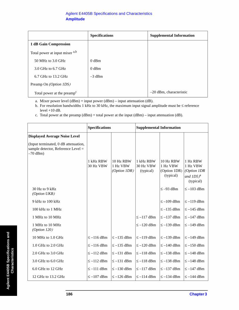
Specifications Supplemental Information
1 dB Gain Compression
Total power at input mixer a,b
50 MHz to 3.0 GHz 0 dBm
3.0 GHz to 6.7 GHz 0 dBm
6.7 GHz to 13.2 GHz –3 dBm
Preamp On (Option 1DS)
Total power at the preampc –20 dBm, characteristic
a. Mixer power level (dBm) = input power (dBm) – input attenuation (dB).b. For resolution bandwidths 1 kHz to 30 kHz, the maximum input signal amplitude must be ≤ reference
level +10 dB.c. Total power at the preamp (dBm) = total power at the input (dBm) – input attenuation (dB).
Specifications Supplemental Information
Displayed Average Noise Level
(Input terminated, 0 dB attenuation, sample detector, Reference Level = –70 dBm)
1 kHz RBW30 Hz VBW
10 Hz RBW1 Hz VBW (Option 1DR)
1 kHz RBW30 Hz VBW
(typical)
10 Hz RBW1 Hz VBW (Option 1DR)
(typical)
1 Hz RBW1 Hz VBW (Option 1DR and 1D5)a
(typical)
30 Hz to 9 kHz(Option UKB)
≤ –93 dBm ≤ −103 dBm
9 kHz to 100 kHz ≤ –109 dBm ≤ −119 dBm
100 kHz to 1 MHz ≤ –135 dBm ≤ −145 dBm
1 MHz to 10 MHz ≤ −117 dBm ≤ −137 dBm ≤ −147 dBm
1 MHz to 10 MHz (Option 120)
≤ −120 dBm ≤ −139 dBm ≤ −149 dBm
10 MHz to 1.0 GHz ≤ −116 dBm ≤ −135 dBm ≤ −119 dBm ≤ −139 dBm ≤ −149 dBm
1.0 GHz to 2.0 GHz ≤ −116 dBm ≤ −135 dBm ≤ −120 dBm ≤ −140 dBm ≤ −150 dBm
2.0 GHz to 3.0 GHz ≤ −112 dBm ≤ −131 dBm ≤ −118 dBm ≤ −138 dBm ≤ −148 dBm
3.0 GHz to 6.0 GHz ≤ −112 dBm ≤ −131 dBm ≤ −118 dBm ≤ −138 dBm ≤ −148 dBm
6.0 GHz to 12 GHz ≤ −111 dBm ≤ −130 dBm ≤ −117 dBm ≤ −137 dBm ≤ −147 dBm
12 GHz to 13.2 GHz ≤ −107 dBm ≤ −126 dBm ≤ −114 dBm ≤ −134 dBm ≤ −144 dBm

Chapter 3 187
Agilent E4405B Specifications and CharacteristicsAmplitude
Agilent E4405B
Specifications and C
haracteristics
Preamp On (Option 1DS) 1 kHz RBW30 Hz VBW
10 Hz RBW1 Hz VBW (Option 1DR)
1 kHz RBW30 Hz VBW
(typical)
10 kHz RBW1 Hz VBW (Option 1DR)
(typical
1 Hz RBW1 Hz VBW (Option 1DR and 1D5)a
(typical)
0 to 55 °C
10 MHz to 1.0 GHz ≤ −131 dBm ≤ −150 dBm
1.0 GHz to 2.0 GHz ≤ −131 dBm ≤ −150 dBm
2.0 GHz to 3.0 GHz ≤ −127 dBm ≤ −146 dBm
20 to 30 °C
1 MHz to 10 MHz ≤ −135 dBm ≤ −155 dBm ≤ −165 dBm
10 MHz to 1.0 GHz ≤ −132 dBm ≤ −151 dBm ≤ −137 dBm ≤ −157 dBm ≤ −167 dBm
1.0 GHz to 2.0 GHz ≤ −132 dBm ≤ −151 dBm ≤ −135 dBm ≤ −155 dBm ≤ −165 dBm
2.0 GHz to 3.0 GHz ≤ −130 dBm ≤ −149 dBm ≤ −132 dBm ≤ −152 dBm ≤ −162 dBm
a. Only available with firmware revision A.08.00 or later
Specifications Supplemental Information
Display Range
Log Scale Ten divisions displayed;0.1, 0.2, 0.5 dB/division and 1 to 20 dB/division in 1 dB steps
RBW ≥ 1 kHz Calibrated 0 to −85 dB from Reference Level
RBW ≤ 300 Hz (Option 1DR) Calibrated 0 to −120 dBa from Reference Level
Linear Scale Ten divisions
Scale Units dBm, dBmV, dBμV, dBμA, A, V, and W
(Option BAA, 106) Add Hz
a. 0 to –70 dB range when span = 0 Hz, or when IF Gain is fixed:(:DISPlay:WINDow:TRACe:Y[:SCALe]:LOG:RANGe:AUTO OFF).
Specifications Supplemental Information
Marker Readout Resolution
Log scale
Specifications Supplemental Information

188 Chapter 3
Agilent E4405B Specifications and CharacteristicsAmplitude
Agi
lent
E44
05B
Spe
cific
atio
ns a
nd
Cha
ract
eris
tics
RBW ≥ 1 kHz
0 to −85 dB from ref level 0.04 dB
RBW ≤ 300 Hz (Option 1DR)
0 to −120 dB from ref level 0.04 dB
Linear scale 0.01% of Reference Level
Fast Sweep Times for Zero Span
(Option AYX)For sweep times
to
Log 0 to −85 dB from ref level 0.3 dB
Linear 0.3% of Reference Level for linear scale
(Option B7D)For sweep times
to
For:
< 40 MHz
Log0 to −85 dB from ref level 0.2 dB
Linear 0.2% of Reference Level
For:
≥ 40 MHz
Log 0 to −85 dB from ref level 0.3 dB
Linear 0.3% of Reference Level
Specifications Supplemental Information
Frequency Response
50 Ω, Absolutea/Relative
Specifications Supplemental Information
sweep points 1–20 MHz----------------------------------------
sweep points 1–100 kHz----------------------------------------
sweep points 1–40 MHz----------------------------------------
sweep points 1–100 kHz----------------------------------------
sweep points 1–sweep time----------------------------------------
sweep points 1–sweep time----------------------------------------

Chapter 3 189
Agilent E4405B Specifications and CharacteristicsAmplitude
Agilent E4405B
Specifications and C
haracteristics
10 dB attenuation(dc coupled)
9 kHz to 3.0 GHz
20 to 30 °C ±0.46 dB ±0.14 dB, typical
0 to 55 °C ±0.76 dB
(ac coupled)
100 kHz to 3.0 GHz
20 to 30 °C ±0.50 dB
0 to 55 °C ±1.0 dB
800 MHz to 1.0 GHz
20 to 30 °C ±0.50 dB ±0.10 dB, typical
0 to 55 °C ±1.0 dB
1.7 GHz to 2.0 GHz
20 to 30 °C ±0.50 dB ±0.08 dB, typical
0 to 55 °C ±1.0 dB
(Option UKB)
100 Hz to 3.0 GHz(dc coupled)
20 to 30 °C ±0.50 dB
0 to 55 °C ±1.00 dB
30 Hz to 3.0 GHz(dc coupled)
20 to 30 °C ±0.5 dB, characteristic
0 to 55 °C ±1.0 dB, characteristic
Absolutea/Relative, Preamp On (Option 1DS)
0 dB attenuation
1 MHz to 3.0 GHz
20 to 30 °C ±1.5 dB
0 to 55 °C ±2.0 dB
800 MHz to 1.0 GHz
20 to 30 °C ±1.5 dB ±0.35 dB, typical
0 to 55 °C ±2.0 dB
Specifications Supplemental Information

190 Chapter 3
Agilent E4405B Specifications and CharacteristicsAmplitude
Agi
lent
E44
05B
Spe
cific
atio
ns a
nd
Cha
ract
eris
tics
1.7 GHz to 2.0 GHz
20 to 30 °C ±1.5 dB ±0.26 dB, typical
0 to 55 °C ±2.0 dB
Preselector centered for frequency >3.0 GHz
10 dB attenuation
3.0 GHz to 6.7 GHz(ac or dc coupled)
Absolutea
20 to 30 °C ±1.5 dB
0 to 55 °C ±2.5 dB
Relative
20 to 30 °C ±1.3 dB
0 to 55 °C ±1.5 dB
6.7 GHz to 13.2 GHz(ac or dc coupled)
Absolutea
20 to 30 °C ±2.0 dB
0 to 55 °C ±3.0 dB
Relative
20 to 30 °C ±1.8 dB
0 to 55 °C ±2.0 dB
a. Absolute frequency response values are referenced to the amplitude at 50 MHz.
Specifications Supplemental Information
Chapter 3 191
Agilent E4405B Specifications and CharacteristicsAmplitude
Agilent E4405B
Specifications and C
haracteristics
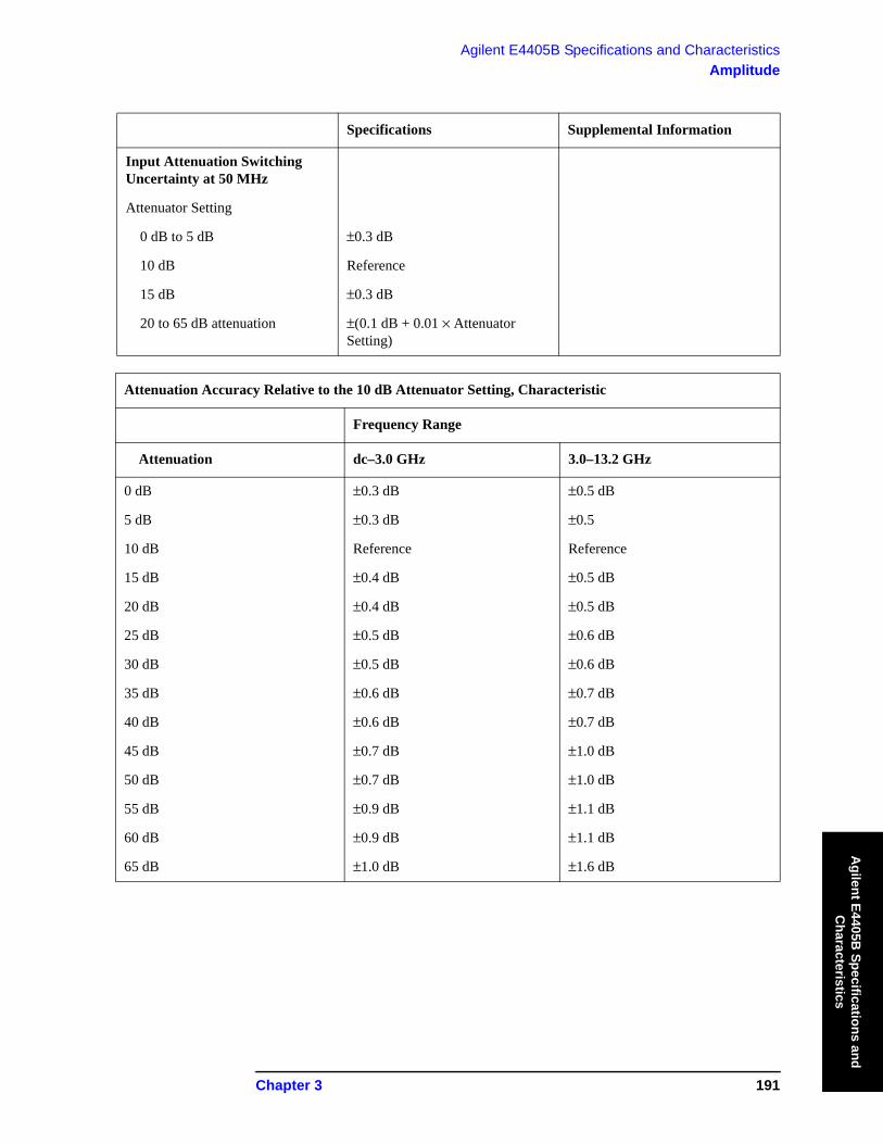
Specifications Supplemental Information
Input Attenuation Switching Uncertainty at 50 MHz
Attenuator Setting
0 dB to 5 dB ±0.3 dB
10 dB Reference
15 dB ±0.3 dB
20 to 65 dB attenuation ±(0.1 dB + 0.01 × Attenuator Setting)
Attenuation Accuracy Relative to the 10 dB Attenuator Setting, Characteristic
Frequency Range
Attenuation dc–3.0 GHz 3.0–13.2 GHz
0 dB ±0.3 dB ±0.5 dB
5 dB ±0.3 dB ±0.5
10 dB Reference Reference
15 dB ±0.4 dB ±0.5 dB
20 dB ±0.4 dB ±0.5 dB
25 dB ±0.5 dB ±0.6 dB
30 dB ±0.5 dB ±0.6 dB
35 dB ±0.6 dB ±0.7 dB
40 dB ±0.6 dB ±0.7 dB
45 dB ±0.7 dB ±1.0 dB
50 dB ±0.7 dB ±1.0 dB
55 dB ±0.9 dB ±1.1 dB
60 dB ±0.9 dB ±1.1 dB
65 dB ±1.0 dB ±1.6 dB
192 Chapter 3
Agilent E4405B Specifications and CharacteristicsAmplitude
Agi
lent
E44
05B
Spe
cific
atio
ns a
nd
Cha
ract
eris
tics
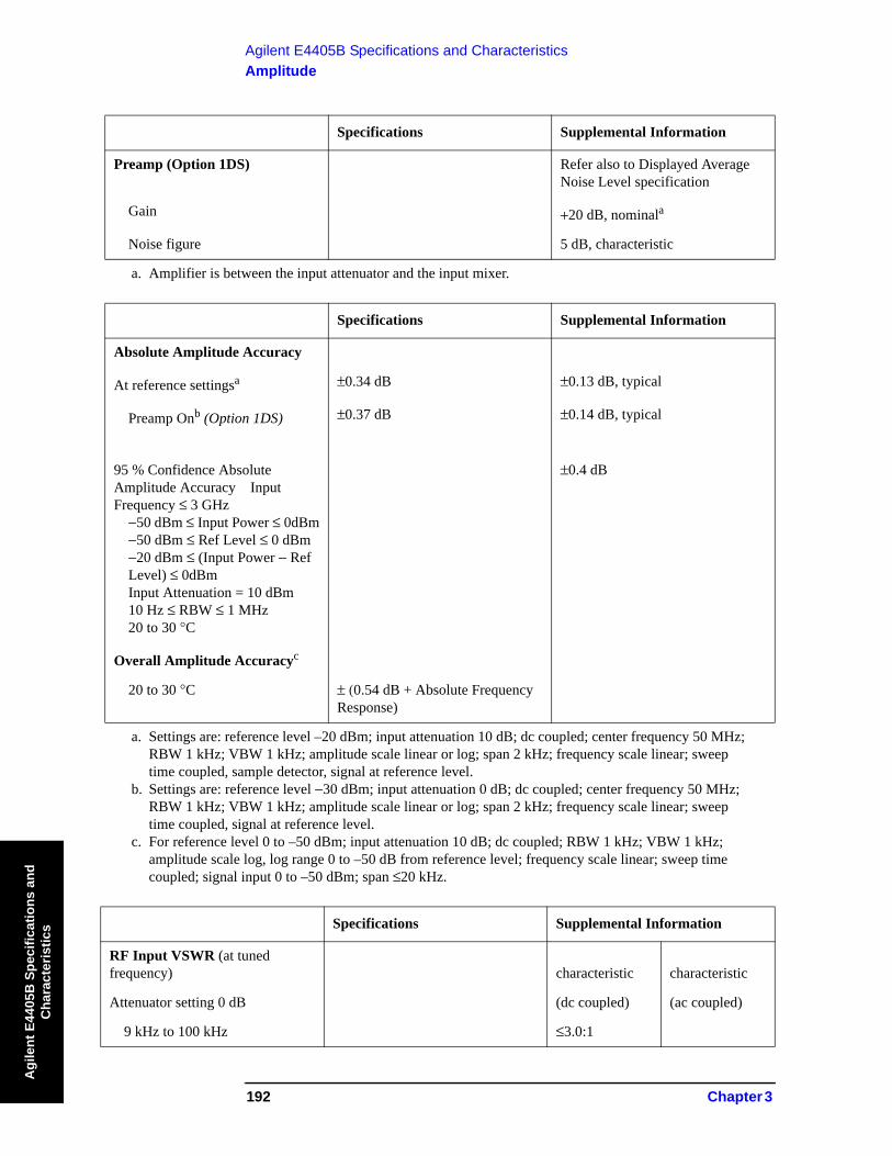
Specifications Supplemental Information
Preamp (Option 1DS) Refer also to Displayed Average Noise Level specification
Gain +20 dB, nominala
Noise figure 5 dB, characteristic
a. Amplifier is between the input attenuator and the input mixer.
Specifications Supplemental Information
Absolute Amplitude Accuracy
At reference settingsa ±0.34 dB ±0.13 dB, typical
Preamp Onb (Option 1DS) ±0.37 dB ±0.14 dB, typical
95 % Confidence Absolute Amplitude Accuracy Input Frequency ≤ 3 GHz
−50 dBm ≤ Input Power ≤ 0dBm−50 dBm ≤ Ref Level ≤ 0 dBm−20 dBm ≤ (Input Power − RefLevel) ≤ 0dBmInput Attenuation = 10 dBm10 Hz ≤ RBW ≤ 1 MHz20 to 30 °C
±0.4 dB
Overall Amplitude Accuracyc
20 to 30 °C ± (0.54 dB + Absolute Frequency Response)
a. Settings are: reference level –20 dBm; input attenuation 10 dB; dc coupled; center frequency 50 MHz; RBW 1 kHz; VBW 1 kHz; amplitude scale linear or log; span 2 kHz; frequency scale linear; sweep time coupled, sample detector, signal at reference level.
b. Settings are: reference level −30 dBm; input attenuation 0 dB; dc coupled; center frequency 50 MHz; RBW 1 kHz; VBW 1 kHz; amplitude scale linear or log; span 2 kHz; frequency scale linear; sweep time coupled, signal at reference level.
c. For reference level 0 to –50 dBm; input attenuation 10 dB; dc coupled; RBW 1 kHz; VBW 1 kHz; amplitude scale log, log range 0 to –50 dB from reference level; frequency scale linear; sweep time coupled; signal input 0 to –50 dBm; span ≤20 kHz.
Specifications Supplemental Information
RF Input VSWR (at tuned frequency) characteristic characteristic
Attenuator setting 0 dB (dc coupled) (ac coupled)
9 kHz to 100 kHz ≤3.0:1

Chapter 3 193
Agilent E4405B Specifications and CharacteristicsAmplitude
Agilent E4405B
Specifications and C
haracteristics
100 kHz to 13.2 GHz ≤3.0:1 ≤3.0:1
100 Hz to 100 kHz (Option UKB)
≤1.1:1
Attenuator setting 5 dB (dc coupled) (ac coupled)
9 kHz to 100 kHz ≤2.0:1
100 kHz to 300 kHz ≤1.4:1 ≤2.3:1
300 kHz to 1.0 MHz ≤1.4:1 ≤1.6:1
1.0 MHz to 3.0 GHz ≤1.4:1 ≤1.4:1
3.0 GHz to 6.7 GHz ≤1.4:1 ≤1.7:1
6.7 GHz to 13.2 GHz ≤1.7:1 ≤1.9:1
100 Hz to 100 kHz (Option UKB)
≤1.1:1
Attenuator setting 10 to 65 dB (dc coupled) (ac coupled)
9 kHz to 100 kHz ≤2.0:1
100 kHz to 300 kHz ≤1.3:1 ≤2.1:1
300 kHz to 1.0 MHz ≤1.3:1 ≤1.5:1
1.0 MHz to 3.0 GHz ≤1.3:1 ≤1.3:1
3.0 GHz to 6.7 GHz ≤1.3:1 ≤1.5:1
6.7 GHz to 13.2 GHz ≤1.5:1 ≤1.7:1
100 Hz to 100 kHz(Option UKB)
≤1.1:1
Specifications Supplemental Information
Auto Alignmenta
Sweep-to-sweep variation ±0.1 dB, characteristic
a. Set Auto Align to Off and use Align Now, All to eliminate this variation.
Specifications Supplemental Information
Resolution Bandwidth Switching Uncertainty (at Reference Level)
1 kHz RBW Reference
3 kHz to 3 MHz RBW ±0.3 dB
5 MHz RBW ±0.6 dB
Specifications Supplemental Information
194 Chapter 3
Agilent E4405B Specifications and CharacteristicsAmplitude
Agi
lent
E44
05B
Spe
cific
atio
ns a
nd
Cha
ract
eris
tics
10 Hz to 300 Hz RBW (Option 1DR)
±0.3 dB
1 Hz to 3 Hz RBW (Option 1DR and 1D5)a
±0.3 dB
a. Firmware revision A.08.00 or later.
Specifications Supplemental Information
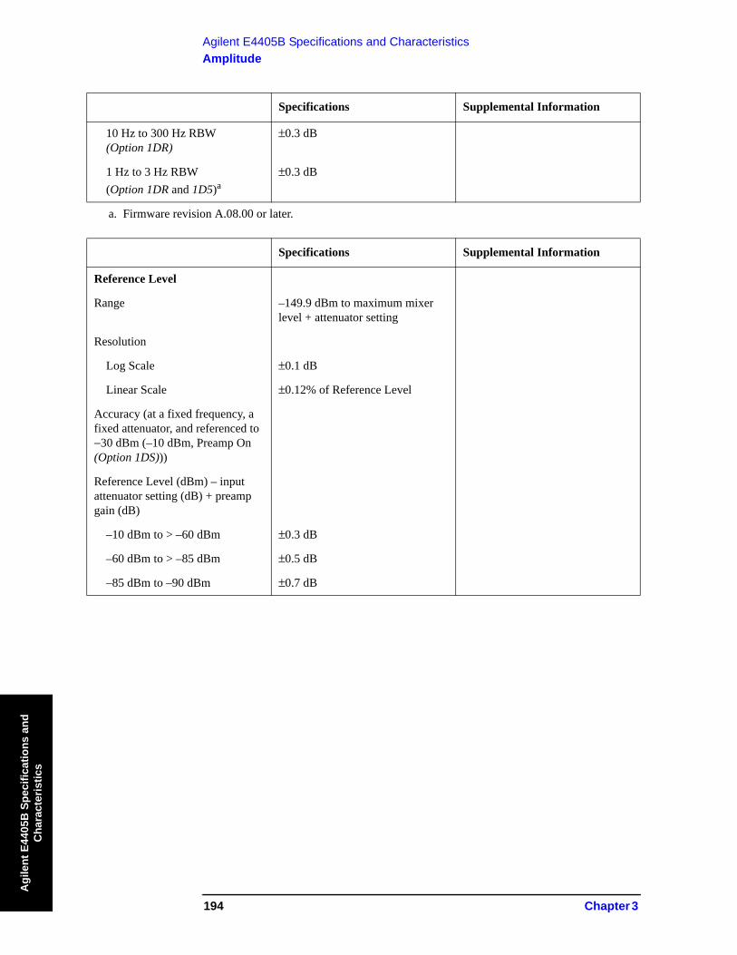
Reference Level
Range –149.9 dBm to maximum mixer level + attenuator setting
Resolution
Log Scale ±0.1 dB
Linear Scale ±0.12% of Reference Level
Accuracy (at a fixed frequency, a fixed attenuator, and referenced to −30 dBm (–10 dBm, Preamp On (Option 1DS)))
Reference Level (dBm) – input attenuator setting (dB) + preamp gain (dB)
–10 dBm to > –60 dBm ±0.3 dB
–60 dBm to > –85 dBm ±0.5 dB
–85 dBm to –90 dBm ±0.7 dB
Specifications Supplemental Information

Chapter 3 195
Agilent E4405B Specifications and CharacteristicsAmplitude
Agilent E4405B
Specifications and C
haracteristics
Specifications Supplemental Information
Display Scale Switching Uncertainty
Switching betweenLinear and Log
±0.15 dB at reference level
Log Scale Switching No error
Specifications Supplemental Information
Display Scale Fidelity
Log Maximum Cumulative
RBW ≥ 1 kHz
dB Below Reference Level
0 dB Reference 0 dB
> 0 to 10 dB ±0.3 dB ±0.08 dB, typical
> 10 to 20 dB ±0.4 dB ±0.09 dB, typical
> 20 to 30 dB ±0.5 dB ±0.10 dB, typical
> 30 to 40 dB ±0.6 dB ±0.23 dB, typical
> 40 to 50 dB ±0.7 dB ±0.35 dB, typical
> 50 to 60 dB ±0.7 dB ±0.35 dB, typical
> 60 to 70 dB ±0.8 dB ±0.39 dB, typical
> 70 to 80 dB ±0.8 dB ±0.46 dB, typical
> 80 to 85 dB ±1.15 dB ±0.79 dB, typical
RBW ≤ 300 Hz (Option 1DR)
Span > 0 Hz
Auto range On
0 to 98 dBa belowreference level
±(0.3 dB + 0.01 × dB from reference level)
> 98 to 120 dB belowreference level
±2.0 dB, characteristic
Auto range Offb
0 to 60 dBa belowreference level
±(0.3 dB + 0.015 × dB from reference level)
> 60 to 70 dB belowreference level
±1.5 dB

196 Chapter 3
Agilent E4405B Specifications and CharacteristicsAmplitude
Agi
lent
E44
05B
Spe
cific
atio
ns a
nd
Cha
ract
eris
tics
Span = 0 Hz
0 to 60 dBa belowreference level
±(0.3 dB + 0.015 × dB from reference level)
> 60 to 70 dB belowreference level
±1.5 dB
Log Incremental Accuracy
0 to 80 dBa,c below reference level
±0.4 dB/4 dB
Linear Accuracy ±2% of Reference Level
a. 0 to 30 dB for RBW = 200 Hzb. The SCPI command for auto range off is:
(:DISPlay:WINDow:TRACe:Y[:SCALe]:LOG:RANGe:AUTO OFF)c. 0 to 50 dB for RBWs ≤ 300 Hz and span = 0 Hz, or when auto ranging is off.
Specifications Supplemental Information
Spurious Responses
Second Harmonic Distortion
Input Signal
10 MHz to 500 MHz < −65 dBc for −30 dBm signal at input mixera
+35 dBm SHI (second harmonic intercept)
500 MHz to 1.5 GHz < −75 dBc for −30 dBm signal at input mixera
+45 dBm SHI
1.5 GHz to 2.0 GHz < −85 dBc for −10 dBm signal at input mixera
+75 dBm SHI
2.0 GHz to 3.35 GHz < −100 dBcb for −10 dBm signal at input mixera
+90 dBm SHI
3.35 GHz to 6.6 GHz < −100 dBca for −10 dBm signal at input mixera
+90 dBm SHI
Preamp On (Option 1DS)10 MHz to 1.5 GHz
–5 dBm SHI, characteristic
Third Order Intermodulation Distortion
10 MHz to 100 MHz +7 dBm TOI (third order intercept), characteristic
Specifications Supplemental Information
Chapter 3 197
Agilent E4405B Specifications and CharacteristicsAmplitude
Agilent E4405B
Specifications and C
haracteristics
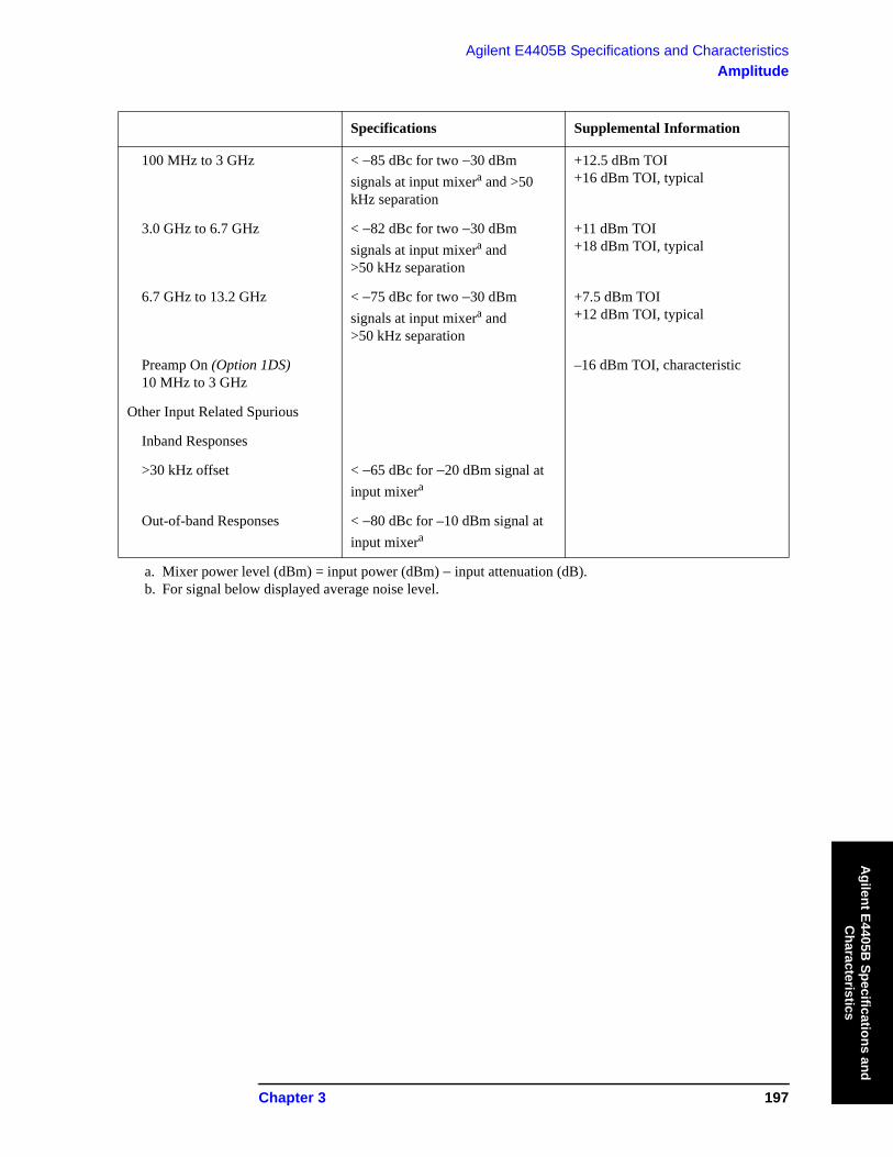
100 MHz to 3 GHz < −85 dBc for two −30 dBm signals at input mixera and >50 kHz separation
+12.5 dBm TOI+16 dBm TOI, typical
3.0 GHz to 6.7 GHz < −82 dBc for two −30 dBm signals at input mixera and >50 kHz separation
+11 dBm TOI +18 dBm TOI, typical
6.7 GHz to 13.2 GHz < −75 dBc for two −30 dBm signals at input mixera and >50 kHz separation
+7.5 dBm TOI +12 dBm TOI, typical
Preamp On (Option 1DS)10 MHz to 3 GHz
–16 dBm TOI, characteristic
Other Input Related Spurious
Inband Responses
>30 kHz offset < −65 dBc for −20 dBm signal at input mixera
Out-of-band Responses < −80 dBc for –10 dBm signal at input mixera
a. Mixer power level (dBm) = input power (dBm) − input attenuation (dB).b. For signal below displayed average noise level.
Specifications Supplemental Information
198 Chapter 3
Agilent E4405B Specifications and CharacteristicsAmplitude
Agi
lent
E44
05B
Spe
cific
atio
ns a
nd
Cha
ract
eris
tics
Specifications Supplemental Information
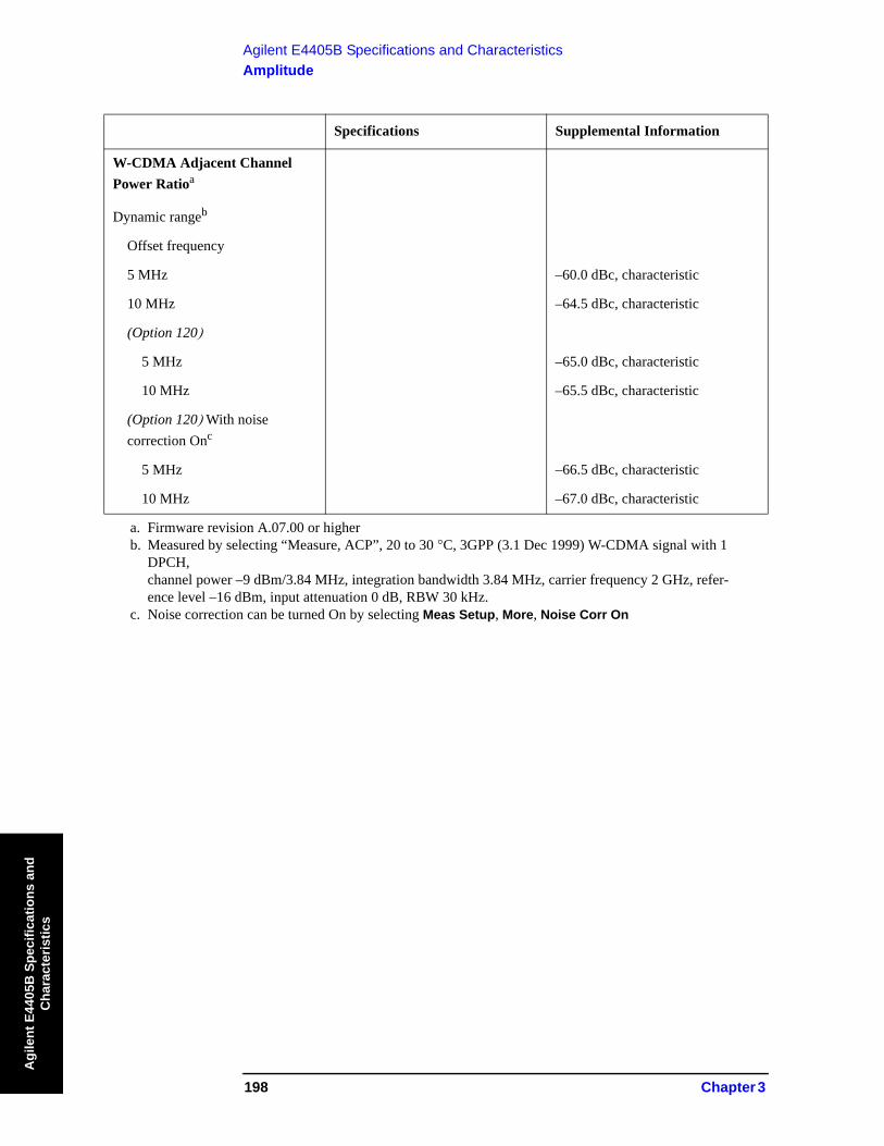
W-CDMA Adjacent Channel Power Ratioa
Dynamic rangeb
Offset frequency
5 MHz –60.0 dBc, characteristic
10 MHz –64.5 dBc, characteristic
(Option 120)
5 MHz –65.0 dBc, characteristic
10 MHz –65.5 dBc, characteristic
(Option 120) With noisecorrection Onc
5 MHz –66.5 dBc, characteristic
10 MHz –67.0 dBc, characteristic
a. Firmware revision A.07.00 or higherb. Measured by selecting “Measure, ACP”, 20 to 30 °C, 3GPP (3.1 Dec 1999) W-CDMA signal with 1
DPCH, channel power –9 dBm/3.84 MHz, integration bandwidth 3.84 MHz, carrier frequency 2 GHz, refer-ence level –16 dBm, input attenuation 0 dB, RBW 30 kHz.
c. Noise correction can be turned On by selecting Meas Setup, More, Noise Corr On
Chapter 3 199
Agilent E4405B Specifications and CharacteristicsAmplitude
Agilent E4405B
Specifications and C
haracteristics
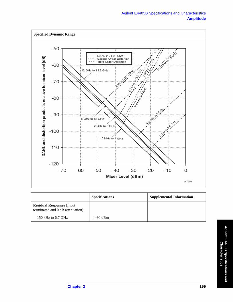
Specified Dynamic Range
Specifications Supplemental Information
Residual Responses (Input terminated and 0 dB attenuation)
150 kHz to 6.7 GHz < −90 dBm
200 Chapter 3
Agilent E4405B Specifications and CharacteristicsOptions
Agi
lent
E44
05B
Spe
cific
atio
ns a
nd
Cha
ract
eris
tics
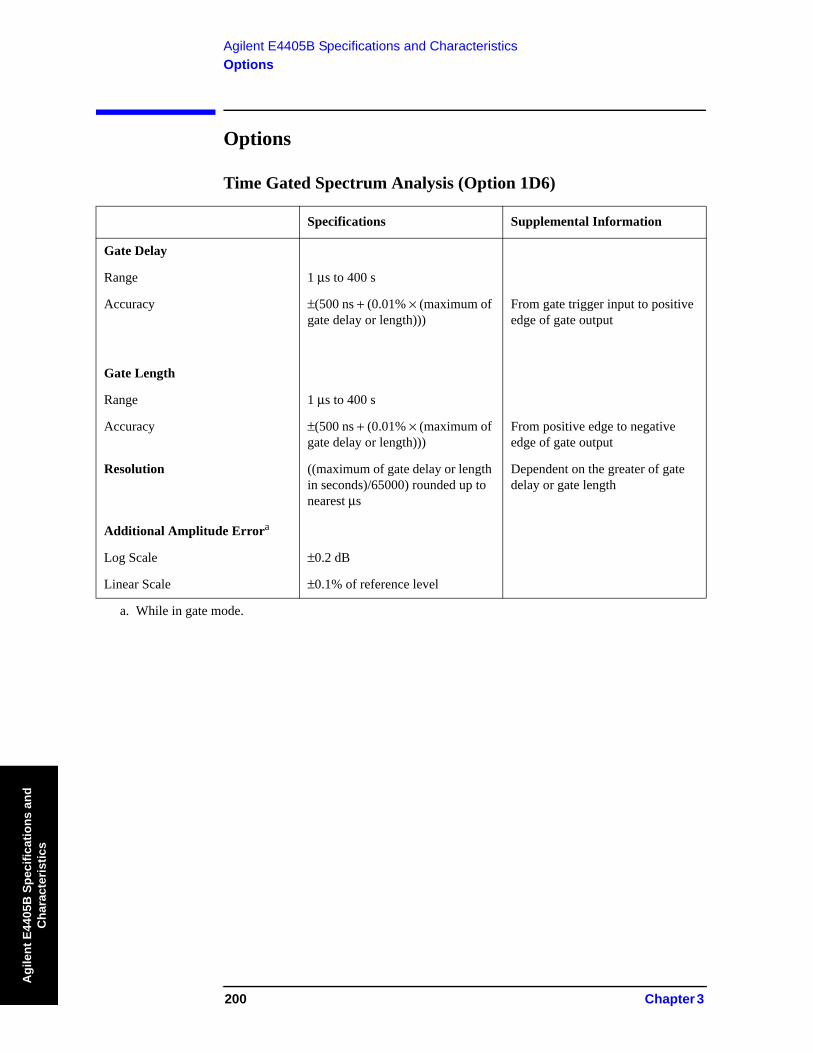
Options
Time Gated Spectrum Analysis (Option 1D6)
Specifications Supplemental Information
Gate Delay
Range 1 μs to 400 s
Accuracy ±(500 ns + (0.01% × (maximum of gate delay or length)))
From gate trigger input to positive edge of gate output
Gate Length
Range 1 μs to 400 s
Accuracy ±(500 ns + (0.01% × (maximum of gate delay or length)))
From positive edge to negative edge of gate output
Resolution ((maximum of gate delay or length in seconds)/65000) rounded up to nearest μs
Dependent on the greater of gate delay or gate length
Additional Amplitude Errora
Log Scale ±0.2 dB
Linear Scale ±0.1% of reference level
a. While in gate mode.

Chapter 3 201
Agilent E4405B Specifications and CharacteristicsOptions
Agilent E4405B
Specifications and C
haracteristics
Tracking Generator (Option 1DN)
The spectrum analyzer/tracking generator combination will meet its specification after a cable (8120-5148) and adapter are connected between RF OUT and INPUT and Align Now, TG has been run.
Specifications Supplemental Information
Warm-up 5 minutes
Specifications Supplemental Information
Output Frequency Range 9 kHz to 3.0 GHz
Specifications Supplemental Information
Minimum Resolution BW 1 kHz Not usable with resolution bandwidths ≤300 Hz (Option 1DR)
Specifications Supplemental Information
Output Power Level
Range –2 to −66 dBm
Resolution 0.1 dB
Absolute Accuracy (at 50 MHz with coupled source attenuator, referenced to –20 dBm)
± 0.75 dB
Vernier
Range 8 dB
Accuracy (with coupled source attenuator, 50 MHz,–20 dBm)
Incremental ±0.2 dB/dB
Cumulative ±0.5 dB, total
Output Attenuator Range 0 to 56 dB in 8 dB steps
Specifications Supplemental Information
Maximum Safe Reverse Level +30 dBm (1 W), 50 Vdc, characteristic
202 Chapter 3
Agilent E4405B Specifications and CharacteristicsOptions
Agi
lent
E44
05B
Spe
cific
atio
ns a
nd
Cha
ract
eris
tics
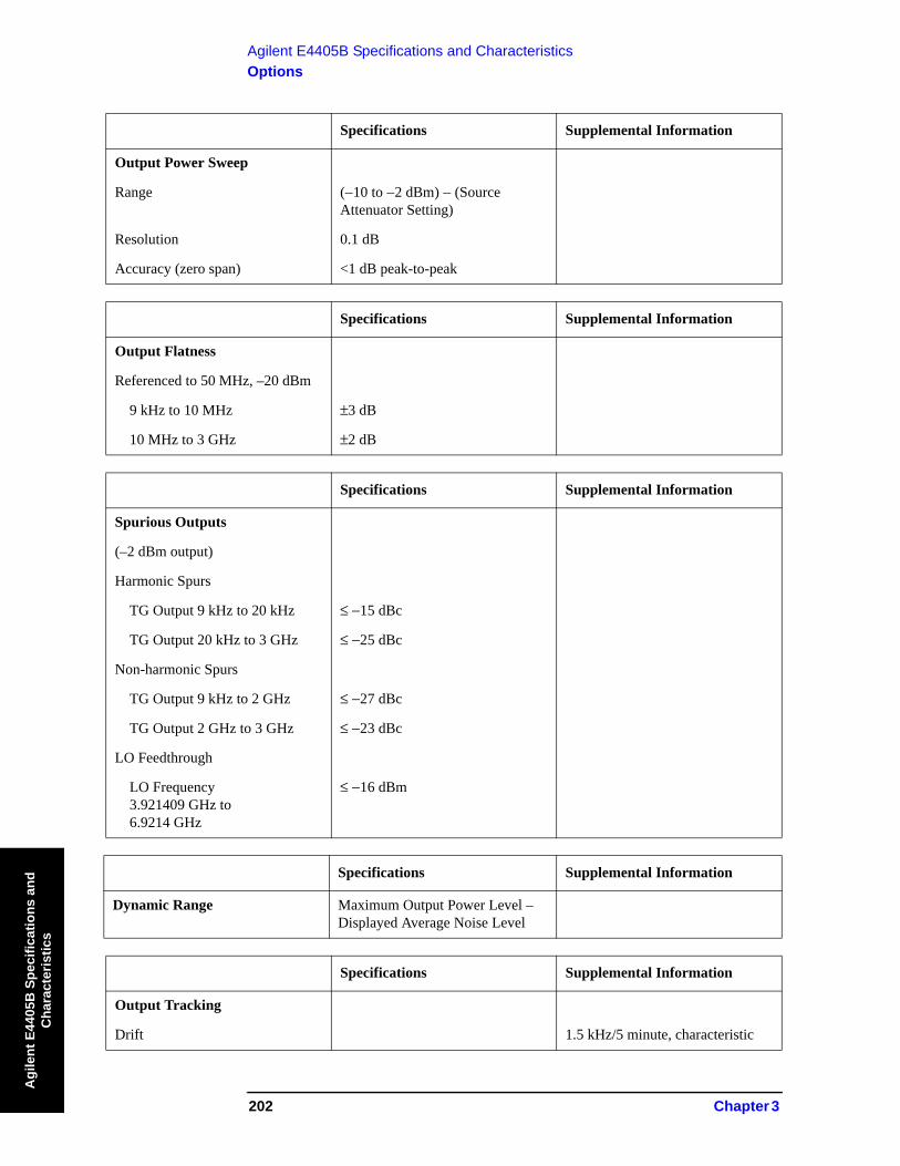
Specifications Supplemental Information
Output Power Sweep
Range (−10 to −2 dBm) − (Source Attenuator Setting)
Resolution 0.1 dB
Accuracy (zero span) <1 dB peak-to-peak
Specifications Supplemental Information
Output Flatness
Referenced to 50 MHz, –20 dBm
9 kHz to 10 MHz ±3 dB
10 MHz to 3 GHz ±2 dB
Specifications Supplemental Information
Spurious Outputs
(–2 dBm output)
Harmonic Spurs
TG Output 9 kHz to 20 kHz ≤ −15 dBc
TG Output 20 kHz to 3 GHz ≤ −25 dBc
Non-harmonic Spurs
TG Output 9 kHz to 2 GHz ≤ −27 dBc
TG Output 2 GHz to 3 GHz ≤ −23 dBc
LO Feedthrough
LO Frequency3.921409 GHz to 6.9214 GHz
≤ −16 dBm
Specifications Supplemental Information
Dynamic Range Maximum Output Power Level – Displayed Average Noise Level
Specifications Supplemental Information
Output Tracking
Drift 1.5 kHz/5 minute, characteristic
Chapter 3 203
Agilent E4405B Specifications and CharacteristicsOptions
Agilent E4405B
Specifications and C
haracteristics
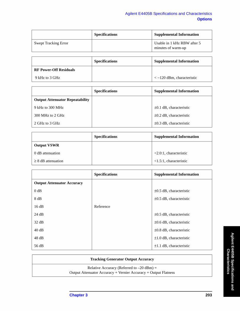
Swept Tracking Error Usable in 1 kHz RBW after 5 minutes of warm-up
Specifications Supplemental Information
RF Power-Off Residuals
9 kHz to 3 GHz < −120 dBm, characteristic
Specifications Supplemental Information
Output Attenuator Repeatability
9 kHz to 300 MHz ±0.1 dB, characteristic
300 MHz to 2 GHz ±0.2 dB, characteristic
2 GHz to 3 GHz ±0.3 dB, characteristic
Specifications Supplemental Information
Output VSWR
0 dB attenuation <2.0:1, characteristic
≥ 8 dB attenuation <1.5:1, characteristic
Specifications Supplemental Information
Output Attenuator Accuracy
0 dB ±0.5 dB, characteristic
8 dB ±0.5 dB, characteristic
16 dB Reference
24 dB ±0.5 dB, characteristic
32 dB ±0.6 dB, characteristic
40 dB ±0.8 dB, characteristic
48 dB ±1.0 dB, characteristic
56 dB ±1.1 dB, characteristic
Tracking Generator Output Accuracy
Relative Accuracy (Referred to –20 dBm) = Output Attenuator Accuracy + Vernier Accuracy + Output Flatness
Specifications Supplemental Information

204 Chapter 3
Agilent E4405B Specifications and CharacteristicsOptions
Agi
lent
E44
05B
Spe
cific
atio
ns a
nd
Cha
ract
eris
tics
Absolute Accuracy = Relative Accuracy (Referred to –20 dBm) + Absolute Accuracy at 50 MHz
Tracking Generator Output Accuracy

Chapter 3 205
Agilent E4405B Specifications and CharacteristicsOptions
Agilent E4405B
Specifications and C
haracteristics
Phase Noise (Option 226)
Carrier Frequency Range Specifications Supplemental Information
E4402B 1 MHz to 3.0 GHz
E4404B 1 MHz to 6.7 GHz
E4405B 1 MHz to 13.2 GHz
E4407B 1 MHz to 26.5 GHz
Measurement Characteristics Specifications Supplemental Information
Measurements Log plot Spot frequencyRMS noiseRMS jitterResidual FM
Maximum number of decades 7 (whole decades only)
Filtering (ratio of video bandwidth to resolution bandwidth)
None (VBW/RBW = 1.0)Little (VBW/RBW = 0.3)Medium (VBW/RBW = 0.1)Maximum (VBW/RBW = 0.03)
Offset Frequency Specifications Supplemental Information
Range 10 kHz to 100 MHz The minimum offset is limited to 10 times the narrowest RBW of the analyzer(Option1DR) 100 Hz to 100 MHz
(Option1DR and 1D5) 10 Hz to 100 MHz
Measurement Accuracy Specifications Supplemental Information
Amplitude Accuracya (carrier frequency 1 MHz to 3.0 GHz)
±1.52 dBb
a. Amplitude accuracy is derived from analyzer specification and characteristics. It is based on a 1 GHz signal at 0 dBm while running the log plot measurement with all other measurement and analyzer set-tings at their factory defaults.
b. This does not include the effect of system noise floor. This error is a function of the signal (phase noise)
to noise (analyzer noise floor) ratio, SN, in decibels. The function is . For example, if the phase noise being measured is 10 dB above the measurement floor, the error due to adding the analyzer’s noise to the UUT is 0.41 dB.
Error 10 log 1 10 SN 10⁄–+( )×=
206 Chapter 3
Agilent E4405B Specifications and CharacteristicsOptions
Agi
lent
E44
05B
Spe
cific
atio
ns a
nd
Cha
ract
eris
tics
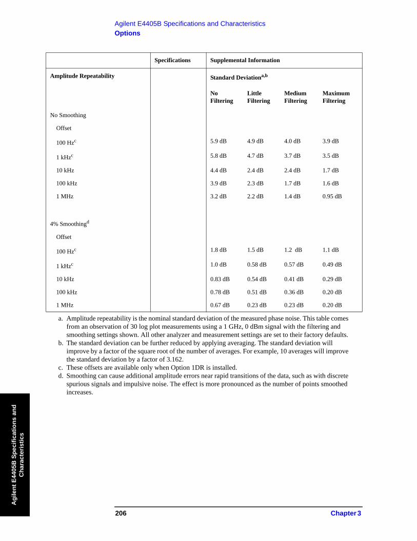
Specifications Supplemental Information
Amplitude Repeatability Standard Deviationa,b
No Filtering
Little Filtering
Medium Filtering
Maximum Filtering
No Smoothing
Offset
100 Hzc 5.9 dB 4.9 dB 4.0 dB 3.9 dB
1 kHzc 5.8 dB 4.7 dB 3.7 dB 3.5 dB
10 kHz 4.4 dB 2.4 dB 2.4 dB 1.7 dB
100 kHz 3.9 dB 2.3 dB 1.7 dB 1.6 dB
1 MHz 3.2 dB 2.2 dB 1.4 dB 0.95 dB
4% Smoothingd
Offset
100 Hzc 1.8 dB 1.5 dB 1.2 dB 1.1 dB
1 kHzc 1.0 dB 0.58 dB 0.57 dB 0.49 dB
10 kHz 0.83 dB 0.54 dB 0.41 dB 0.29 dB
100 kHz 0.78 dB 0.51 dB 0.36 dB 0.20 dB
1 MHz 0.67 dB 0.23 dB 0.23 dB 0.20 dB
a. Amplitude repeatability is the nominal standard deviation of the measured phase noise. This table comes from an observation of 30 log plot measurements using a 1 GHz, 0 dBm signal with the filtering and smoothing settings shown. All other analyzer and measurement settings are set to their factory defaults.
b. The standard deviation can be further reduced by applying averaging. The standard deviation will improve by a factor of the square root of the number of averages. For example, 10 averages will improve the standard deviation by a factor of 3.162.
c. These offsets are available only when Option 1DR is installed. d. Smoothing can cause additional amplitude errors near rapid transitions of the data, such as with discrete
spurious signals and impulsive noise. The effect is more pronounced as the number of points smoothed increases.

Chapter 3 207
Agilent E4405B Specifications and CharacteristicsOptions
Agilent E4405B
Specifications and C
haracteristics
Specifications Supplemental Information
Frequency Offset Accuracya ± 3.7% 0.053 octave
a. The frequency offset error in octaves causes an additional amplitude accuracy error proportional to the product of the frequency error and slope of the phase noise. For example, a 0.01 octave frequency error combined with an 18 dB/octave slope gives 0.18 dB additional amplitude error.
Nominal Phase Noise Normalized to 1 Hz Versus Offset Frequency
ESA E4402B, E4404B, E4405B, and E4407B Spectrum Analyzers

208 Chapter 3
Agilent E4405B Specifications and CharacteristicsOptions
Agi
lent
E44
05B
Spe
cific
atio
ns a
nd
Cha
ract
eris
tics
FM Demodulation and Quasi Peak Detector (Option AYQ)
The FM demodulation characteristics will apply after an Align Now, FM Demod has been run.
Specifications Supplemental Information
Optimum Input Level ≥ (−60 dBm + attenuator setting − preamp gain) and within 30 dB of the reference level
FM Deviation
Range 10 kHz to 1 MHz
Resolution 300Hz, characteristic
Accuracya
FM Rate < FM BW/100, VBW ≥ (30 × FM Rate), RBW > the maximum of (30 × FM deviation) or (30 × FM Rate)
< (2% of FM deviation range + 2 × Resolution), characteristic
Offset Errora 5% of FM Deviation Range + 300 Hz, characteristic
FM Bandwidth (–3 dB)
FM Deviation Range
10 kHz to 40 kHz 0.5 × FM deviation range, characteristic
>40 kHz to 200 kHz 0.5 × FM deviation range, characteristic
>200 kHz to 1 MHz 0.4 × FM deviation range, characteristic
a. In time domain sweeps (span = 0 Hz)

Chapter 3 209
Agilent E4405B Specifications and CharacteristicsOptions
Agilent E4405B
Specifications and C
haracteristics
Specifications Supplemental Information
Quasi-Peak Detector The quasi-peak detector provides the quasi-peak amplitude of pulsed radio frequency (RF) or continuous wave (CW) signals.
The amplitude response conforms to Publication 16 of CISPR Section 1, Clause 2, except as indicated in the Relative Quasi-Peak Response Table.
Relative Quasi-Peak Response to a CISPR Pulse (dB)
Frequency Band
Pulse Repetition Frequency
120 kHz EMI BW0.03 to 1 GHz
9 kHz EMI BW0.15 to 30 MHz
200 Hz EMI BW9 to 150 kHz
1000 Hz +8.0 ± 1.0 +4.5 ± 1.0 N/A
100 Hz 0 dB referencea 0 dB referencea +4.0 ± 1.0
60 Hz N/A N/A +3.0 ± 1.0
25 Hz N/A N/A 0 dB referencea
20 Hz −9.0 ± 1.0 −6.5 ± 1.0 N/A
10 Hz −14.0 ± 1.5 −10.0 ± 1.5 −4.0 ± 1.0
5 Hz N/A N/A −7.5 ± 1.5
2 Hz −26.0 ± 2.0 −20.5 ± 2.0 −13.0 ± 2.0
1 Hz −22.5 ± 2.0 −17.0 ± 2.0
Isolated Pulse −23.5 ± 2.0 −19.0 ± 2.0
a. Reference pulse amplitude accuracy relative to a 66 dBμV CW signal is <1.5 dB as specified in CISPR Publication 16. CISPR reference pulse: 0.044 μVs for 30 MHz to 1.0 GHz, 0.316 μVs for 15 kHz to 30 MHz, and 13.5 μVs for 9 to 150 kHz.
210 Chapter 3
Agilent E4405B Specifications and CharacteristicsOptions
Agi
lent
E44
05B
Spe
cific
atio
ns a
nd
Cha
ract
eris
tics
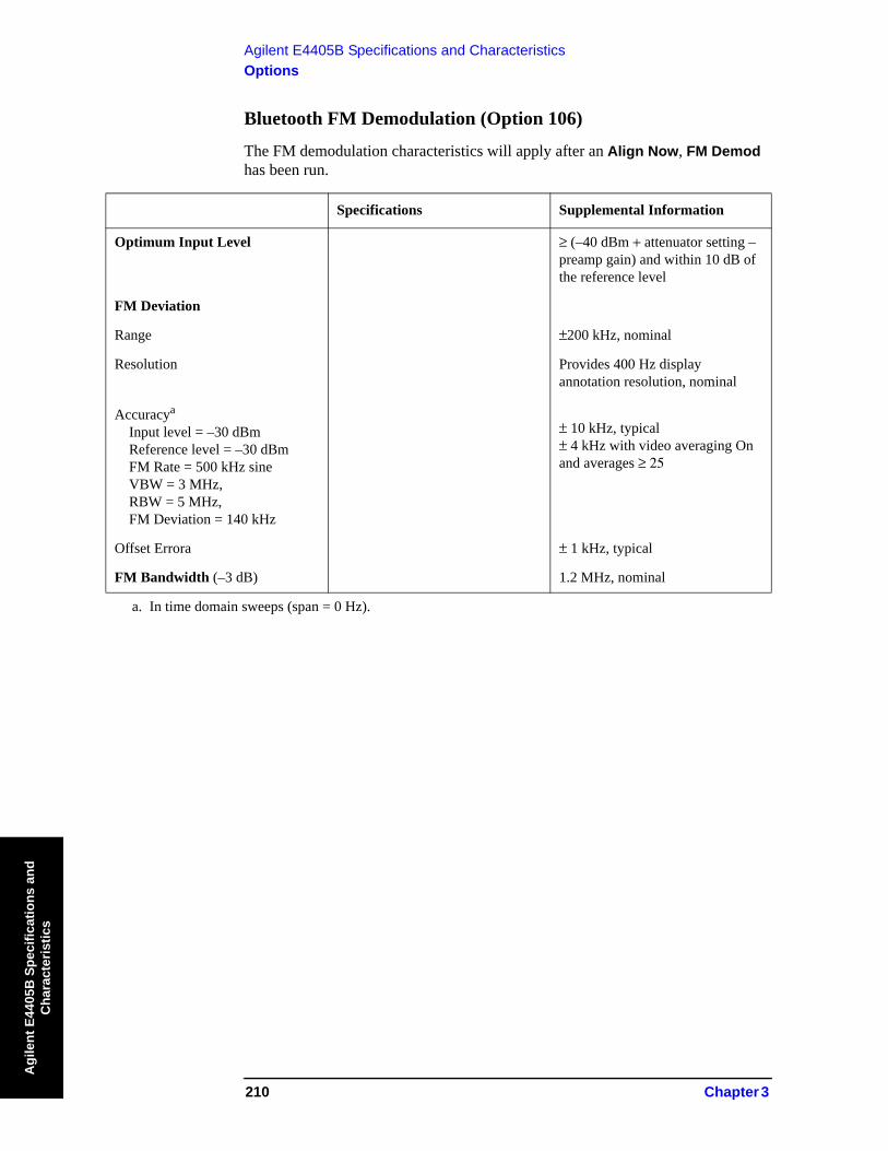
Bluetooth FM Demodulation (Option 106)
The FM demodulation characteristics will apply after an Align Now, FM Demod has been run.
Specifications Supplemental Information
Optimum Input Level ≥ (–40 dBm + attenuator setting – preamp gain) and within 10 dB of the reference level
FM Deviation
Range ±200 kHz, nominal
Resolution Provides 400 Hz display annotation resolution, nominal
Accuracya
Input level = –30 dBmReference level = –30 dBmFM Rate = 500 kHz sineVBW = 3 MHz,RBW = 5 MHz,FM Deviation = 140 kHz
± 10 kHz, typical± 4 kHz with video averaging On and averages ≥ 25
Offset Errora ± 1 kHz, typical
FM Bandwidth (–3 dB) 1.2 MHz, nominal
a. In time domain sweeps (span = 0 Hz).
Chapter 3 211
Agilent E4405B Specifications and CharacteristicsOptions
Agilent E4405B
Specifications and C
haracteristics
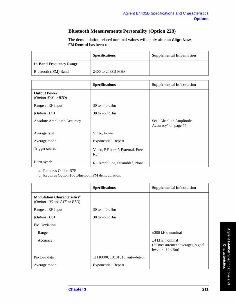
Bluetooth Measurements Personality (Option 228)
The demodulation related nominal values will apply after an Align Now, FM Demod has been run.
Specifications Supplemental Information
In-Band Frequency Range
Bluetooth (ISM) Band 2400 to 2483.5 MHz
Specifications Supplemental Information
Output Power (Option AYX or B7D)
Range at RF Input 30 to –40 dBm
(Option 1DS) 30 to –60 dBm
Absolute Amplitude Accuracy See “Absolute Amplitude Accuracy” on page 55.
Average type Video, Power
Average mode Exponential, Repeat
Trigger source Video, RF bursta, External, Free Run
Burst synch RF Amplitude, Preambleb, None
a. Requires Option B7Eb. Requires Option 106 Bluetooth FM demodulation.
Specifications Supplemental Information
Modulation Characteristicsa (Option 106 and AYX or B7D)
Range at RF Input 30 to –40 dBm
(Option 1DS) 30 to –60 dBm
FM Deviation
Range ±200 kHz, nominal
Accuracy ±4 kHz, nominal(25 measurement averages, signal level > –30 dBm)
Payload data 11110000, 10101010, auto-detect
Average mode Exponential, Repeat

212 Chapter 3
Agilent E4405B Specifications and CharacteristicsOptions
Agi
lent
E44
05B
Spe
cific
atio
ns a
nd
Cha
ract
eris
tics
Trigger source Video, RF burstb, External, Free Run
Burst synch RF Amplitude, Preamblec, None
Limits Δf2/Δf1 lower, Δf1 max lower/upper Δf2
a. The DUT must have frequency hopping disabled.b. Requires Option B7Ec. Requires Option 106 Bluetooth FM demodulation.
Specifications Supplemental Information
Carrier Frequency Drift a(Option 106 and AYX or B7D)
Range at RF Input 30 to –40 dBm
(Option 1DS) 30 to –60 dBm
Measurement range ±100 kHz, nominal
Measurement accuracy ±4 kHz, nominal(25 measurement averages, signal level > –30 dBm)
Average mode Exponential, Repeat
Trigger source Video, RF burstb, External, Free Run
Burst synch Preamblec, None
a. The DUT must have frequency hopping disabled.b. Requires Option B7Ec. Requires Option 106 Bluetooth FM demodulation.
Specifications Supplemental Information
Chapter 3 213
Agilent E4405B Specifications and CharacteristicsOptions
Agilent E4405B
Specifications and C
haracteristics
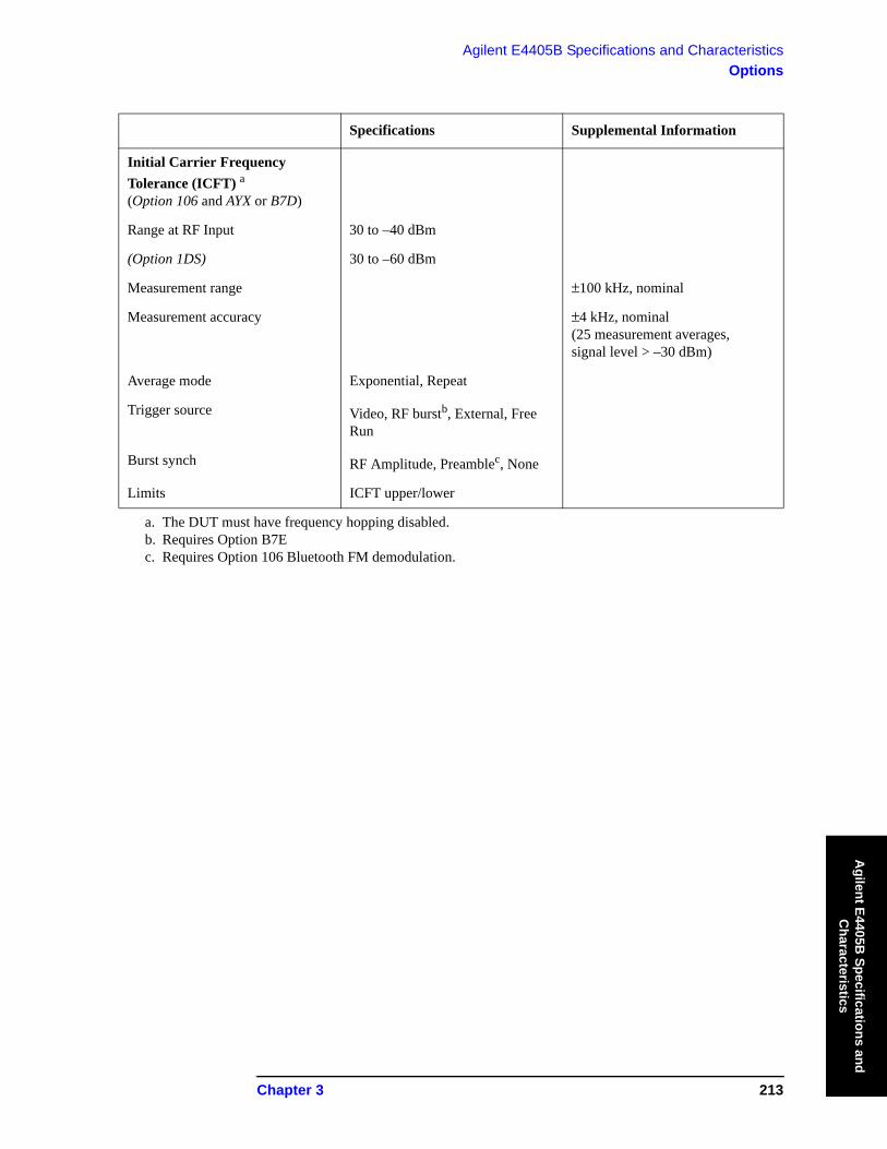
Specifications Supplemental Information
Initial Carrier Frequency Tolerance (ICFT) a(Option 106 and AYX or B7D)
Range at RF Input 30 to –40 dBm
(Option 1DS) 30 to –60 dBm
Measurement range ±100 kHz, nominal
Measurement accuracy ±4 kHz, nominal(25 measurement averages, signal level > –30 dBm)
Average mode Exponential, Repeat
Trigger source Video, RF burstb, External, Free Run
Burst synch RF Amplitude, Preamblec, None
Limits ICFT upper/lower
a. The DUT must have frequency hopping disabled.b. Requires Option B7Ec. Requires Option 106 Bluetooth FM demodulation.

214 Chapter 3
Agilent E4405B Specifications and CharacteristicsOptions
Agi
lent
E44
05B
Spe
cific
atio
ns a
nd
Cha
ract
eris
tics
FM Demodulation (Option BAA)
The FM demodulation characteristics will apply after an Align Now, FM Demod has been run.
Specifications Supplemental Information
Optimum Input Level ≥ (–60 dBm + attenuator setting – preamp gain) and within 30 dB of the reference level
FM Deviation
Range 10 kHz to 1 MHz
Resolution Provides 1 Hz display annotation resolution
FM Deviation Range
10 kHz to 40 kHz 12 Hz, characteristic
>40 kHz to 200 kHz 60 Hz, characteristic
>200 kHz to 1 MHz 300 Hz, characteristic
Accuracya
FM Rate < FM BW/100,VBW ≥ (30 × FM Rate),RBW > the maximum of(30 × FM deviation) or(30 × FM Rate)
< (2% of FM deviation range + 2 × Resolution), characteristic
Offset Errora 5% of FM Deviation Range + 300 Hz, characteristic
FM Bandwidth (–3 dB)
FM Deviation Range
10 kHz to 40 kHz 7.5 × FM deviation range, characteristic
>40 kHz to 200 kHz 1.3 × FM deviation range, characteristic
>200 kHz to 1 MHz 0.3 × FM deviation range, characteristic
a. In time domain sweeps (span = 0 Hz).

Chapter 3 215
Agilent E4405B Specifications and CharacteristicsOptions
Agilent E4405B
Specifications and C
haracteristics
TV Trigger and Picture On Screen (Option B7B)
Option BAA is required.
Specifications Supplemental Information
TV Trigger and Picture On Screen
TV Trigger initiates a sweep of the analyzer after the sync pulse of a selected line of a TV video field. Picture On Screen displays the TV picture on the analyzer display.
Amplitude RequirementsTV Source: SA
TV Source: EXT VIDEO IN
Top 50% of linear display, characteristic
500 mVp–p to 2 Vp–p, characteristic
Compatible Standards NTSC–M, NTSC–Japan, PAL–M, PAL–B,D,G,H,I, PAL–N, PAL–N Combination, SECAM-L
Field Selection Entire frame, even, odd
Sync Polarity Positive or negative
TV Trigger
Line Selection 1 to 525, or 1 to 625, standard dependent

216 Chapter 3
Agilent E4405B Specifications and CharacteristicsOptions
Agi
lent
E44
05B
Spe
cific
atio
ns a
nd
Cha
ract
eris
tics
cdmaOne Measurement Personality (Option BAC)
Unless otherwise noted, all specifications are with RF input range auto, default cdmaOne measurement settings, and in the in-band frequency range. Option B72 is required.
Specifications Supplemental Information
In-Band Frequency Range
Cellular bands 824 to 870 MHz
869 to 925 MHz
PCS bands 1715 to 1780 MHz
1805 to 1870 MHz
1850 to 1910 MHz
1930 to 1990 MHz
Specifications Supplemental Information
Adjacent Channel Power Ratioa
Carrier power range at RF Input30 to –20 dBm
Dynamic rangeb Referenced to average power of carrier in 1.23 MHz BW
OffsetFrequency
IntegrationBW
750 kHz 30 kHz –70.0 dBc, characteristic
885 kHz 30 kHz –73.5 dBc, characteristic
1.25625 MHz 12.5 kHz –78.0 dBc, characteristic
1.98 MHz 30 kHz –75.5 dBc, characteristic
2.75 MHz 1 MHz –60.5 dBc, characteristic
Relative accuracyc See Display Scale Fidelity
Resolution 0.01 dB
a. This measurement is available with personality revisions of A.02.00 or later.b. IS-97A nominal base station test model levels (fraction of carrier power); Pilot: 0.20 (–7.0 dBc), Sync:
0.0471 (–13.3 dBc), Paging: 0.1882 (–7.3 dBc), 6 Traffic channels: 0.09412 (–10.3 dBc)c. Does not include uncertainty due to noise.

Chapter 3 217
Agilent E4405B Specifications and CharacteristicsOptions
Agilent E4405B
Specifications and C
haracteristics
Specifications Supplemental Information
Channel Power(1.23 MHz Integration BW)
Integration BW range 1 kHz to 10 MHz
Range at RF Input 30 to ∠70 dBm
Absolute power accuracy for in-band signal(Mean channel power at RF Input, plus any external attenuation, excluding mismatch error)
Cellular Bands
30 to –5 dBm20 to 30 °C ±0.82 dB ±0.39 dB, typical
0 to 55 °C ±1.09 dB
–5 to –25 dBm20 to 30 °C ±0.78 dB ±0.37 dB, typical
0 to 55 °C ±1.05 dB
–25 to –45 dBm20 to 30 °C ±0.69 dB ±0.21 dB, typical
0 to 55 °C ±0.94 dB
–45 to –55 dBm
20 to 30 °C ±0.77 dB ±0.28 dB, typical
0 to 55 °C ±0.96 dB
–55 to –70 dBm20 to 30 °C ±0.89 dB ±0.38 dB, typical
0 to 55 °C ±1.21 dB
PCS Bands
30 to –5 dBm20 to 30 °C ±0.78 dB ±0.26 dB, typical
0 to 55 °C ±1.11 dB
–5 to –25 dBm20 to 30 °C ±0.74 dB ±0.23 dB, typical
0 to 55 °C ±1.02 dB
–25 to –45 dBm20 to 30 °C ±0.71 dB ±0.26 dB, typical
0 to 55 °C ±0.99 dB
–45 to –55 dBm20 to 30 °C ±0.79 dB ±0.33 dB, typical

218 Chapter 3
Agilent E4405B Specifications and CharacteristicsOptions
Agi
lent
E44
05B
Spe
cific
atio
ns a
nd
Cha
ract
eris
tics
0 to 55 °C ±1.01 dB
–55 to –70 dBm20 to 30 °C ±0.91 dB ±0.43 dB, typical
0 to 55 °C ±1.26 dB
Specifications Supplemental Information
Channel power relative power accuracy (same channel, different Tx power, input attenuator fixed, RF input range manual).
See Display Scale Fidelity
Specifications Supplemental Information
Receive Channel Power
Absolute Power AccuracyCellular bands
30 to 0 dBm ±0.95 dB ±0.53 dB, typical
0 to –85 dBm ±1.46 dB ±0.63 dB, typical
PCS bands30 to 0 dBm ±0.97 dB ±0.52 dB, typical
0 to –85 dBm ±1.35 dB ±0.59 dB, typical
Preamp (Option 1DS)Cellular and PCS bands
30 to –80 dBm ±1.88 dB ±1.15 dB, typical
–80 to –100 dBm ±2.95 dB ±1.93 dB, typical
Specifications Supplemental Information
Occupied Bandwidth
Carrier power range 30 to –45 dBm
Frequency resolution of occupied BW
1.88 kHz
Frequency accuracy of occupied BW(1.23 MHz channel BW)
±15 kHz, characteristic
Frequency resolution of delta frequency
3.75 kHz
Frequency accuracy of delta frequency
± (35 kHz + frequency reference error × carrier frequency), characteristic
Specifications Supplemental Information

Chapter 3 219
Agilent E4405B Specifications and CharacteristicsOptions
Agilent E4405B
Specifications and C
haracteristics
Specifications Supplemental Information
Code Domain Power (Requires Options 1D5, B7D, and B7E. Measurement interval ≥1.25 ms unless otherwise noted.)
Carrier power range at RF Input(Pilot channel power > –11 dBc)
30 to –13 dBm 30 to –65 dBma, characteristic
Preamp (Option 1DS) 30 to –30 dBm 30 to –82 dBma, characteristic
Measurement interval range 0.5 ms to 26.67 ms
Code domain power
Display dynamic range 50 dB
Accuracy (Walsh channel powerwithin 20 dB of total power)
±0.2 dB, typical
Displayed resolution 0.01 dB
Other reported power parameters(dB referenced to total power)
Average active traffic, maximum inactive traffic, average inactive traffic, pilot, paging, sync channels
Carrier frequency error (Measurement interval ≥2.5 ms)
Excludes frequency reference error.
Input frequency error range ±100 kHz ±200 kHz, typical
Accuracy ±10 Hz ±7 Hz, typical
Displayed resolution Four digits
Estimated Rho
Range 0.9 to 1.0 0.5 to 1.0b
Accuracy(With 9 channels active overthe specified range)c
±0.02, characteristic
Displayed resolution 0.0001
Pilot time offset From even second signal to start of PN sequence
Range –13.33 ms to +13.33 ms
Accuracy ±150 ns
Displayed resolution Four digits
Code domain timing Pilot to code channel time tolerance
Range ±200 ns
220 Chapter 3
Agilent E4405B Specifications and CharacteristicsOptions
Agi
lent
E44
05B
Spe
cific
atio
ns a
nd
Cha
ract
eris
tics
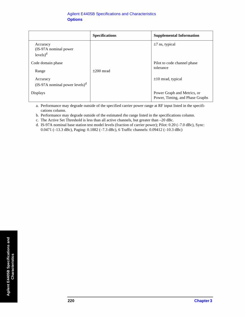
Accuracy (IS-97A nominal powerlevels)d
±7 ns, typical
Code domain phase Pilot to code channel phase tolerance
Range ±200 mrad
Accuracy (IS-97A nominal power levels)d
±10 mrad, typical
Displays Power Graph and Metrics, or Power, Timing, and Phase Graphs
a. Performance may degrade outside of the specified carrier power range at RF input listed in the specifi-cations column.
b. Performance may degrade outside of the estimated rho range listed in the specifications column.c. The Active Set Threshold is less than all active channels, but greater than –20 dBc.d. IS-97A nominal base station test model levels (fraction of carrier power); Pilot: 0.20 (–7.0 dBc), Sync:
0.0471 (–13.3 dBc), Paging: 0.1882 (–7.3 dBc), 6 Traffic channels: 0.09412 (–10.3 dBc)
Specifications Supplemental Information
Chapter 3 221
Agilent E4405B Specifications and CharacteristicsOptions
Agilent E4405B
Specifications and C
haracteristics
Specifications Supplemental Information
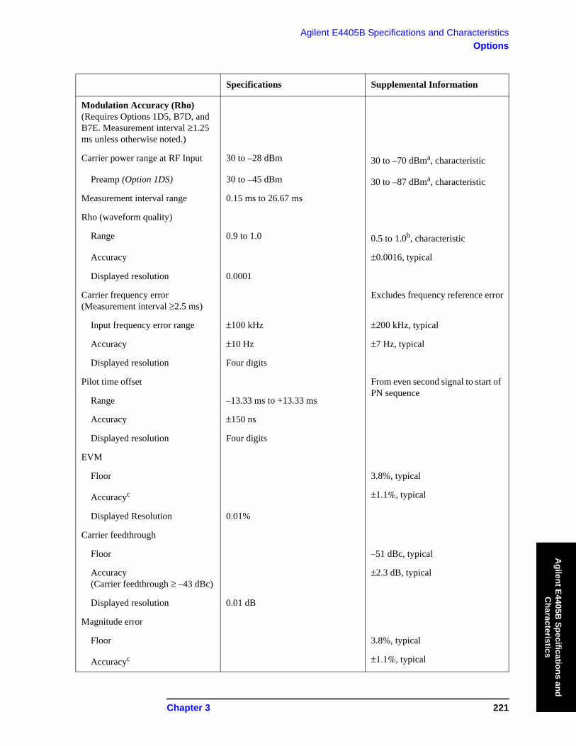
Modulation Accuracy (Rho) (Requires Options 1D5, B7D, and B7E. Measurement interval ≥1.25 ms unless otherwise noted.)
Carrier power range at RF Input 30 to –28 dBm 30 to –70 dBma, characteristic
Preamp (Option 1DS) 30 to –45 dBm 30 to –87 dBma, characteristic
Measurement interval range 0.15 ms to 26.67 ms
Rho (waveform quality)
Range 0.9 to 1.0 0.5 to 1.0b, characteristic
Accuracy ±0.0016, typical
Displayed resolution 0.0001
Carrier frequency error (Measurement interval ≥2.5 ms)
Excludes frequency reference error
Input frequency error range ±100 kHz ±200 kHz, typical
Accuracy ±10 Hz ±7 Hz, typical
Displayed resolution Four digits
Pilot time offset From even second signal to start of PN sequence
Range –13.33 ms to +13.33 ms
Accuracy ±150 ns
Displayed resolution Four digits
EVM
Floor 3.8%, typical
Accuracyc ±1.1%, typical
Displayed Resolution 0.01%
Carrier feedthrough
Floor –51 dBc, typical
Accuracy(Carrier feedthrough ≥ –43 dBc)
±2.3 dB, typical
Displayed resolution 0.01 dB
Magnitude error
Floor 3.8%, typical
Accuracyc ±1.1%, typical

222 Chapter 3
Agilent E4405B Specifications and CharacteristicsOptions
Agi
lent
E44
05B
Spe
cific
atio
ns a
nd
Cha
ract
eris
tics
Displayed resolution 0.01%
Phase error
Accuracyc ±0.65 degrees, typical
Displayed resolution 0.01 degrees
Displays Numeric results orNumeric results and IQ graph
a. Performance may degrade outside of the specified carrier power range at RF input listed in the specifi-cations column.
b. Performance may degrade outside of the rho range listed in the specifications column.c. Accuracy does not include the effects of the EVM floor. The measurement variance increases as the
result approaches the EVM floor.
Specifications Supplemental Information
Spur Close (In Band)
Carrier power range at RF Input 30 to –12 dBm
Dynamic rangeInput power30 to 25 dBm 55 dB
25 to 20 dBm 50 dB
20 to –12 dBm 46 dB
Relative accuracy ±(2.7 dB + 0.01 × (dB from reference level))
±(0.3 dB + 0.01 × (dB from reference level)), typical
Displayed resolution 0.01 dB
Specifications Supplemental Information
Out-of-Band Spuriousa Refer to the Amplitude specifications section in this guide.
a. The out-of-band measurement is made with the user-defined tables with 20 frequency ranges each (up to the top 10 spurs per range, 100 spurs maximum). Table parameters include frequency range, RBW, video BW, detector type, and amplitude test limits.
Specifications Supplemental Information
Receiver Spurious Emissions
Spurious emission power range –20 to –83 dBm
Preamp On (Option 1DS) –40 to –101 dBm
Specifications Supplemental Information

Chapter 3 223
Agilent E4405B Specifications and CharacteristicsOptions
Agilent E4405B
Specifications and C
haracteristics
Absolute spurious emission power accuracy
–20 to –60 dBm ±2.0 dB ±1.1 dB, typical
–60 to –83 dBm ±3.8 dB ±2.7 dB, typical
Preamp On (Option 1DS)–40 to –70 dBm ±2.5 dB ±1.3 dB, typical
–70 to –101 dBm ±4.0 dB ±2.6 dB, typical
Specifications Supplemental Information
External CorrectionExternal attenuation,external gain
Range –90 to 90 dB
Resolution 0.01 dB
Specifications Supplemental Information

224 Chapter 3
Agilent E4405B Specifications and CharacteristicsOptions
Agi
lent
E44
05B
Spe
cific
atio
ns a
nd
Cha
ract
eris
tics
Specifications Supplemental Information
Trigger
Trigger source(Actual available choices dependent on measurement)
Free run, external
(Option B7D and B7E) Add RF Burst, frame
Delay triggerRange 0 to 500 ms
Resolution 300 ns
RF burst trigger level(Option B7E)
0 to –25 dBc
Trigger slope(External and RF burst)
Positive/Negative
Frame timing period 50 ns to 13.6533 s
Frame synchronizing source External frame sync Rear panel connector labelled EXT FRAME SYNC (Option B7D)
Frame synchronizing slope Positive/Negative
Specifications Supplemental Information
Demod Trigger Source
Even second input(Frame trigger only, Option B7D and B7E)
Rear panel connector labelled EXT FRAME SYNC
PN offset range 0 to 511 x 64 [chips]
Chapter 3 225
Agilent E4405B Specifications and CharacteristicsOptions
Agilent E4405B
Specifications and C
haracteristics
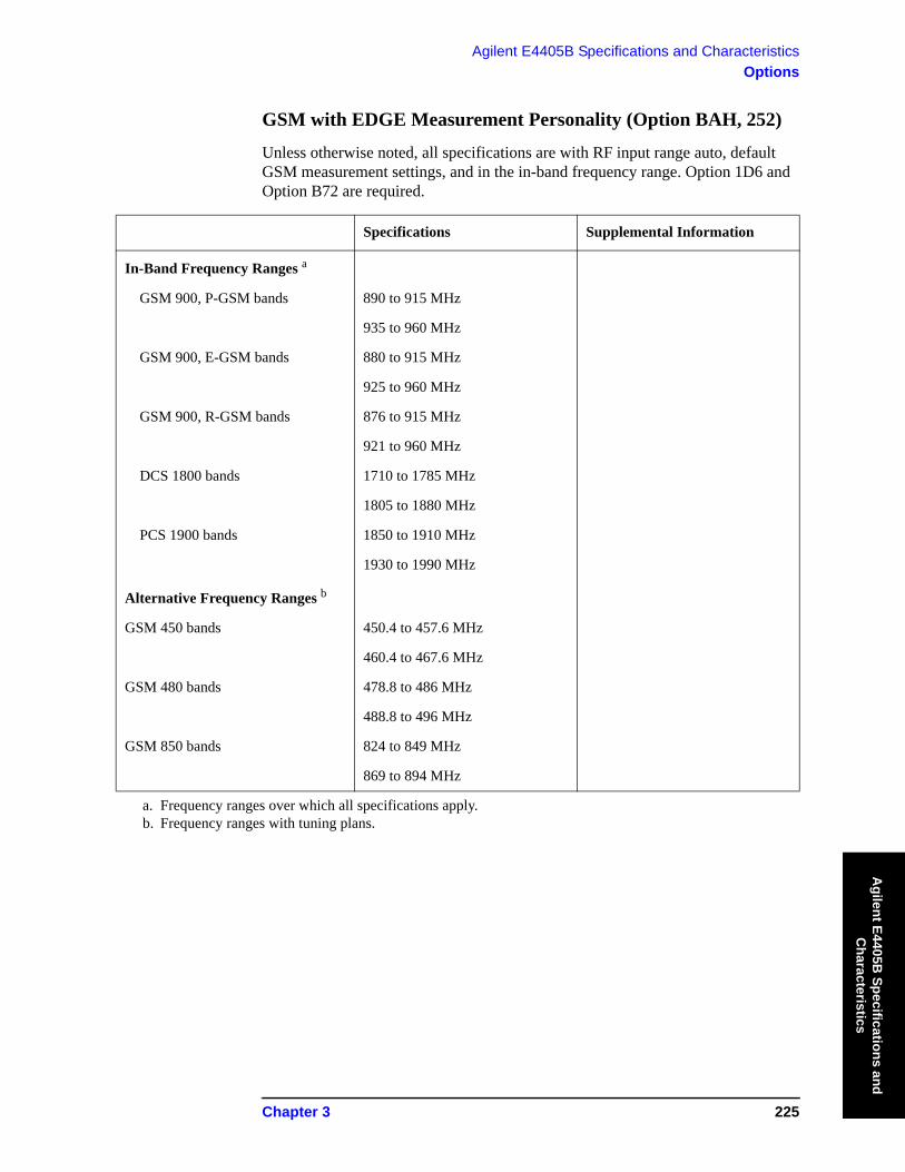
GSM with EDGE Measurement Personality (Option BAH, 252)
Unless otherwise noted, all specifications are with RF input range auto, default GSM measurement settings, and in the in-band frequency range. Option 1D6 and Option B72 are required.
Specifications Supplemental Information
In-Band Frequency Ranges a
GSM 900, P-GSM bands 890 to 915 MHz
935 to 960 MHz
GSM 900, E-GSM bands 880 to 915 MHz
925 to 960 MHz
GSM 900, R-GSM bands 876 to 915 MHz
921 to 960 MHz
DCS 1800 bands 1710 to 1785 MHz
1805 to 1880 MHz
PCS 1900 bands 1850 to 1910 MHz
1930 to 1990 MHz
Alternative Frequency Ranges b
GSM 450 bands 450.4 to 457.6 MHz
460.4 to 467.6 MHz
GSM 480 bands 478.8 to 486 MHz
488.8 to 496 MHz
GSM 850 bands 824 to 849 MHz
869 to 894 MHz
a. Frequency ranges over which all specifications apply.b. Frequency ranges with tuning plans.

226 Chapter 3
Agilent E4405B Specifications and CharacteristicsOptions
Agi
lent
E44
05B
Spe
cific
atio
ns a
nd
Cha
ract
eris
tics
Specifications Supplemental Information
Transmitter Power(Requires Option B7D or AYX)
Range at RF Input 30 to –60 dBm
Absolute power accuracy for in-band signal(Mean channel power at RF Input, plus any external attenuation, excluding mismatch error
P-GSM, E-GSM, and R-GSM Bands
30 to –20 dBm20 to 30 °C ±0.81 dB ±0.34 dB, typical
0 to 55 °C ±1.25 dB
–20 to –30 dBm20 to 30 °C ±0.74 dB ±0.31 dB, typical
0 to 55 °C ±1.06 dB
–30 to –40 dBm20 to 30 °C ±0.79 dB ±0.31 dB, typical
0 to 55 °C ±1.05 dB
–40 to –50 dBm20 to 30 °C ±0.95 dB ±0.47 dB, typical
0 to 55 °C ±1.15 dB
–50 to –60 dBm20 to 30 °C ±1.09 dB ±0.60 dB, typical
0 to 55 °C ±1.27 dB
DCS 1800 and PCS 1900 Bands
30 to –20 dBm20 to 30 °C ±0.77 dB ±0.29 dB, typical
0 to 55 °C ±1.27 dB
–20 to –30 dBm20 to 30 °C ±0.70 dB ±0.28 dB, typical
0 to 55 °C ±1.05 dB
–30 to –40 dBm20 to 30 °C ±0.75 dB ±0.28 dB, typical
0 to 55 °C ±1.04 dB
–40 to –50 dBm20 to 30 °C ±0.91 dB ±0.44 dB, typical
Chapter 3 227
Agilent E4405B Specifications and CharacteristicsOptions
Agilent E4405B
Specifications and C
haracteristics
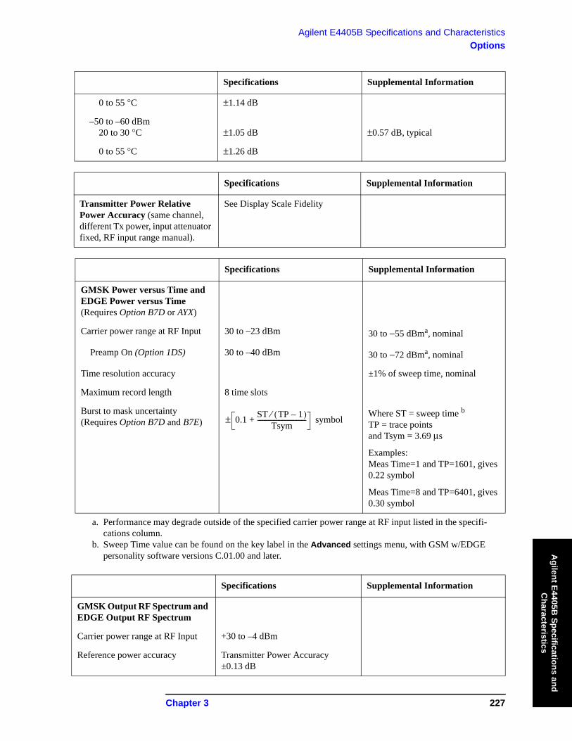
0 to 55 °C ±1.14 dB
–50 to –60 dBm20 to 30 °C ±1.05 dB ±0.57 dB, typical
0 to 55 °C ±1.26 dB
Specifications Supplemental Information
Transmitter Power Relative Power Accuracy (same channel, different Tx power, input attenuator fixed, RF input range manual).
See Display Scale Fidelity
Specifications Supplemental Information
GMSK Power versus Time and EDGE Power versus Time(Requires Option B7D or AYX)
Carrier power range at RF Input 30 to –23 dBm 30 to −55 dBma, nominal
Preamp On (Option 1DS) 30 to –40 dBm 30 to −72 dBma, nominal
Time resolution accuracy ±1% of sweep time, nominal
Maximum record length 8 time slots
Burst to mask uncertainty(Requires Option B7D and B7E) symbol
Where ST = sweep time bTP = trace pointsand Tsym = 3.69 μs
Examples:Meas Time=1 and TP=1601, gives 0.22 symbol
Meas Time=8 and TP=6401, gives 0.30 symbol
a. Performance may degrade outside of the specified carrier power range at RF input listed in the specifi-cations column.
b. Sweep Time value can be found on the key label in the Advanced settings menu, with GSM w/EDGE personality software versions C.01.00 and later.
Specifications Supplemental Information
GMSK Output RF Spectrum and EDGE Output RF Spectrum
Carrier power range at RF Input +30 to –4 dBm
Reference power accuracy Transmitter Power Accuracy±0.13 dB
Specifications Supplemental Information
0.1 ST TP 1–( )⁄Tsym
-------------------------------+±

228 Chapter 3
Agilent E4405B Specifications and CharacteristicsOptions
Agi
lent
E44
05B
Spe
cific
atio
ns a
nd
Cha
ract
eris
tics
Relative accuracya
Due to modulation
Offsets ≤1200 kHz ±0.83 dB
Offsets ≥1800 kHz ±0.96 dB
Due to switching ±1.63 dB
Spectrum due to modulation displayed dynamic rangeb,c
Non-Option 120 Option 120
100 kHz offset d 67.5 dB 67.5 dB
200 kHz offset d 69.5 dB 71.9 dB
250 kHz offset d 70.2 dB 73.3 dB
400 kHz offsetGSM dEDGE
71.7 dB 76.3 dB67 dB, nominal e
600 kHz to 1200 kHz offset 72.8 dB 78.8 dB
1.8 MHz offset 69.9 dB 76.3 dB
6 MHz offset 70.1 dB 77.1 dB
Spectrum due to switching transients displayed dynamic rangeb,c
Non-Option 120
Option 120
400 kHz offset 62.5 dB 67.1 dB
600 kHz offset 63.6 dB 69.6 dB
1200 kHz offset 65.1 dB 72.5 dB
1800 kHz offset 65.4 dB 72.7 dB
a. Does not include uncertainty due to noise.b. Previously available GSM measurements options for ESA specified dynamic range for CW signals only.
These specifications apply for GSM and EDGE signals.c. Using default settings, the RBW filter has a corrected noise BW and impulse BW equivalent to five-pole
synchronously tuned filter.d. The dynamic range for offsets under 400 kHz is not directly observable because the signal spectrum
obscures the result. These dynamic range specifications are derived from phase noise specifications.
Specifications Supplemental Information
Phase and Frequency Error (Requires Option 1D5, B7D, and B7E)
Carrier power range at RF Input 30 to –23 dBm 30 to –55 dBma, nominal
Specifications Supplemental Information

Chapter 3 229
Agilent E4405B Specifications and CharacteristicsOptions
Agilent E4405B
Specifications and C
haracteristics
e. The analyzer performance can be dominated by third-order distortion products. These products depend on the mixer level. Their relative level will vary by 10 dB as the mixer level (input RF power minus attenuation) varies over a 5 dB range. When the Input Attenuator is auto coupled, the resolution of the attenuator keeps the mixer level in a 5 dB range. The indicated nominal performance was observed at the worst-case mixer level. Increasing the input attenuation by 10 dB from the auto coupled setting will improve the dynamic range for EDGE signals to very close to that for GSM signals at the 400 kHz off-set. The optimum mixer level for dynamic range is approximately −15 dBm for EDGE at 400 kHz off-set; the auto coupled setting is controlled to be in the −4 to −9 dBm range to optimize the trade off between compression errors and noise for wider offsets.
Preamp On (Option 1DS) 30 to –40 dBm 30 to –72 dBma, nominal
Phase errorRange 0 to 180°
Displayed resolution 0.01°
Accuracy (Averages ≥10)Peak ±2.1° ±1.5°, typical
RMS ±1.1° ±0.6°, typical
Frequency error Excludes frequency reference error
Initial frequency error range ±100 kHz
Accuracy (Avg. Type = Mean, Averages ≥10) ±10 Hz ±5 Hz, typical
I/Q offset range –10 to –46 dBc
Burst sync time uncertainty ±0.1 bit
Displays Numeric summary
a. Performance may degrade outside of the specified carrier power range at RF input listed in the specifi-cations column.
Specifications Supplemental Information

230 Chapter 3
Agilent E4405B Specifications and CharacteristicsOptions
Agi
lent
E44
05B
Spe
cific
atio
ns a
nd
Cha
ract
eris
tics
Specifications Supplemental Information
Transmit Band Spurious
Carrier power range at RF Input 30 to –12 dBm, typical
Dynamic rangeUpper and lower adjacentsegments 55 dB, nominal
Upper and lower segments 44 dB, nominal
Relative accuracy ±(0.3 dB + 0.01 × (dB from reference level)), nominal
Displayed resolution 0.01 dB
Specifications Supplemental Information
Out-of-Band Spuriousa
Absolute Spurious Power Accuracy
Refer to the Amplitude specifications section in this guide.
Sensitivityb
RBW
1 kHz –95 dBm, nominal
3 kHz –90 dBm, nominal
10 kHz –85 dBm, nominal
30 kHz –78 dBm, nominal
100 kHz –71 dBm, nominal
300 kHz –64 dBm, nominal
1 MHz –57 dBm, nominal
3 MHz –50 dBm, nominal
a. The out-of-band spurious measurement is made in accordance with the tables defined in the appropri-ate 3GPP specification document. The measurement is made over several frequency ranges (up to 10 spurs per range, 100 spurs maximum).
b. With input attentuation of 5 dB. For all other attenuation settings, add (input attenuation – 5) dB.

Chapter 3 231
Agilent E4405B Specifications and CharacteristicsOptions
Agilent E4405B
Specifications and C
haracteristics
Specifications Supplemental Information
Receive Band Spurious
Spurious emission power rangea
–20 to –73 dBm, nominal
Preamp On (Option 1DS) –40 to –91 dBm, nominal
Absolute spurious emission power accuracy
–20 to –60 dBm ±1.4 dB, nominal
–60 to –73 dBm ±2.0 dB, nominal
Preamp on (Option 1DS)–40 to –70 dBm ±1.8 dB, nominal
–70 to –91 dBm ±3.0 dB, nominal
a. Requires bandpass filter centered on receive band, peak detector mode, 0 dB attenuation, 100 kHz RBW. Does not include insertion loss of bandpass filter.
232 Chapter 3
Agilent E4405B Specifications and CharacteristicsOptions
Agi
lent
E44
05B
Spe
cific
atio
ns a
nd
Cha
ract
eris
tics
Specifications Supplemental Information
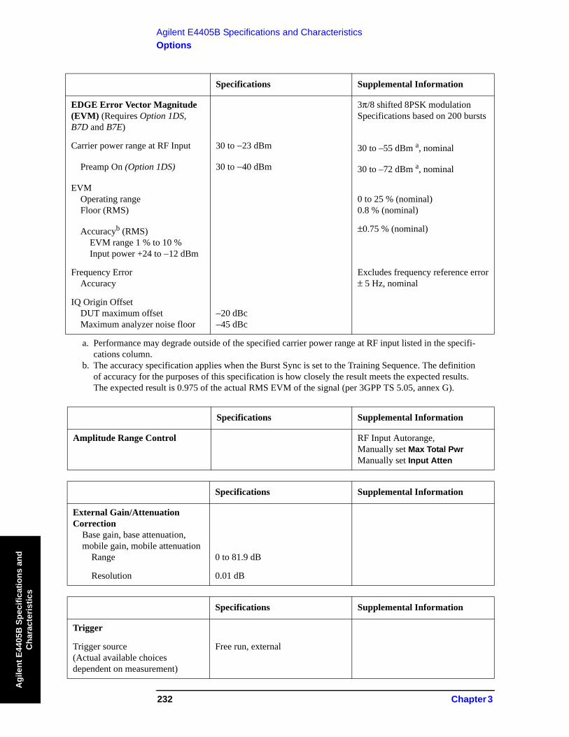
EDGE Error Vector Magnitude (EVM) (Requires Option 1DS, B7D and B7E)
3π/8 shifted 8PSK modulation Specifications based on 200 bursts
Carrier power range at RF Input 30 to −23 dBm 30 to –55 dBm a, nominal
Preamp On (Option 1DS) 30 to −40 dBm 30 to –72 dBm a, nominal
EVMOperating rangeFloor (RMS)
0 to 25 % (nominal)0.8 % (nominal)
Accuracyb (RMS)EVM range 1 % to 10 %Input power +24 to −12 dBm
±0.75 % (nominal)
Frequency ErrorAccuracy
Excludes frequency reference error± 5 Hz, nominal
IQ Origin OffsetDUT maximum offsetMaximum analyzer noise floor
−20 dBc−45 dBc
a. Performance may degrade outside of the specified carrier power range at RF input listed in the specifi-cations column.
b. The accuracy specification applies when the Burst Sync is set to the Training Sequence. The definition of accuracy for the purposes of this specification is how closely the result meets the expected results. The expected result is 0.975 of the actual RMS EVM of the signal (per 3GPP TS 5.05, annex G).
Specifications Supplemental Information
Amplitude Range Control RF Input Autorange,Manually set Max Total Pwr Manually set Input Atten
Specifications Supplemental Information
External Gain/Attenuation Correction
Base gain, base attenuation,mobile gain, mobile attenuation
Range 0 to 81.9 dB
Resolution 0.01 dB
Specifications Supplemental Information
Trigger
Trigger source(Actual available choices dependent on measurement)
Free run, external

Chapter 3 233
Agilent E4405B Specifications and CharacteristicsOptions
Agilent E4405B
Specifications and C
haracteristics
(Option B7D and B7E) Add RF burst and frame
RF burst trigger(Option B7E)
Peak carrier power rangea 30 to –25 dBm 30 to –30 dBm, typical
Preamp On (Option 1DS) 30 to –45 dBm 30 to –50 dBm, typical
Trigger level range 0 to –25 dB relative to signal peak
a. With trigger level set to –6 dB.
Specifications Supplemental Information
Burst Sync(Requires Option AYX or B7D)
Source(Actual available choices dependent on measurement)
RF amplitude, none
(Option B7D and B7E) Add training sequence
Training sequence code GSM defined 0 to 7Auto (search) or Manual
Burst type Normal (TCH and CCH)Sync (SCH)Access (RACH)
Specifications Supplemental Information

234 Chapter 3
Agilent E4405B Specifications and CharacteristicsOptions
Agi
lent
E44
05B
Spe
cific
atio
ns a
nd
Cha
ract
eris
tics
Noise Figure Measurement Personality and Hardware(Option 219) Specifications.
Specifications Supplemental Information
+28 V PULSED Noise source driveUsed by option 219
Connector type 50 Ω BNC(f)
Output voltage
On 28.0 V ±0.1 V 60mA peak
Off <1V
SNS SERIES NOISE SOURCE For use with Agilent Technologies SNS Series noise sources
Specifications Supplemental Information
Noise Figure Uncertainty Calculatora
10 MHz to 3 GHz Using internal preamp (Option 1DS), and RBW=1 MHz
Noise Source ENR Measurement Range
Instrument Uncertaintyb
4.5 to 6.5 dB 0 to 20 dB ±0.24 dB
12 to 17 dB 0 to 30 dB ±0.41 dB
20 to 22 dB 0 to 35 dB ±0.46 dB
3 to 26.5 GHzc No internal preamp
Instrument Uncertainty Nominally the same as for the 10 MHz to 3 GHz range;External preamp cautiond
3 to 10 GHz Well-controlled preselectore
10 to 20 GHz Good preselector stabilityf
20 to 26.5 GHz Preselector Drift Effectsg
a. The figures given in the table are for the uncertainty added by the ESA instrument only. To compute the total uncertainty for your noise figure measurement, you need to take into account other factors including: DUT NF, Gain and Match; Instrument NF, Gain Uncertainty and Match; Noise source ENR uncertainty and Match. The computations can be performed with the uncertainty calculator included with the Noise Figure Measurement Personality. Go to Mode Setup then select Uncertainty Calcula-tor. Similar calculators are also available on the Agilent web site; go to www.agilent.com/find/nfu.

Chapter 3 235
Agilent E4405B Specifications and CharacteristicsOptions
Agilent E4405B
Specifications and C
haracteristics
b. "Instrument Uncertainty" is defined for noise figure analysis as uncertainty due to relative amplitude uncertainties encountered in the analyzer when making the measurements required for a noise figure or gain computation. The relative amplitude uncertainty is given by the relative display scale fidelity, also known as incremental log fidelity. The uncertainty of the analyzer is multiplied within the computation by an amount that depends on the Y factor to give the total uncertainty of the noise figure or gain mea-surement.See Agilent App Note 57-2, literature number 5952-3706E for details on the use of this specification. Jitter (amplitude variations) will also affect the accuracy of results. The standard deviation of the mea-sured result decreases by a factor of the square root of the Resolution Bandwidth used and by the square root of the number of averages. ESA uses the 1 MHz resolution Bandwidth as default since this is the widest bandwidth with uncompromised accuracy.
c. For this frequency range, the Instrument Noise Figure Uncertainty is still well controlled, but other accuracy issues become critical. Because there is no internal preamplifier in this range, the Instrument Noise Figure is much higher than in the range below 3 GHz. This causes the effect on total measure-ment Noise Figure Uncertainty of the Instrument Gain Uncertainty to be much higher, and that Instru-ment Gain Uncertainty is in turn much higher than in the range below 3 GHz because of the effects of the preselector, explained in subsequent footnotes. As a result, when the DUT has high gain, the total measurement Noise Figure Uncertainty computed with the Uncertainty Calculator can still be excel-lent, but modest and low gain devices can have very high uncertainties of noise figure. Graphs that fol-low demonstrate. The first graph shows the computed measurement NF uncertainty with no preamp, and shows how much gain is required to achieve good accuracy. The second graph shows computed measurement NF uncertainty when using an external preamp with 23 dB gain and 6 dB NF. Both graphs were plotted using the uncertainty calculator with the assumptions shown.
d. An external preamp can reduce the total NF measurement uncertainty substantially because it will reduce the effective noise figure of the measurement system, and thus it will reduce the sensitivity of the total NF uncertainty to the Instrument Gain Uncertainty. But if the signal levels into such an exter-nal preamp are large enough, that external preamp may experience some compression. The compres-sion differences between the noise-source-on and noise-source-off states causes an error that must be added to Instrument Noise Figure Uncertainty for use in the Noise Figure Uncertainty Calculator. Such signal levels are quite likely for the case where the DUT has some combination of high gain, high noise figure and wide bandwidth.As an example, we will use the Agilent 83006A as the external preamplifier. The measurement will be made at 18 GHz. The typical gain is 25 dB and the noise figure is 7 dB. We will assume the DUT has 20 dB gain, a 10 dB NF, and a passband from 5 to 30 GHz. We will use a noise source with 17 dB ENR. When the noise source is on, the DUT output can be computed by starting with kT (−174 dBm/Hz) and adding 10·log(30 GHz to 5 GHz) or 104 dB, giving −70 dBm for the thermal noise. Add to this the ENR of the noise source (17 dB) combined with the NF of the DUT (10 dB) to give an equivalent input ENR of 18 dB, thus −52 dBm input noise power. Add the gain of the DUT (20 dB) to find the DUT output power to be −32 dBm. The noise figure of the external preamp may be neglected. The external preamplifier gain of 25 dB adds, giving a preamplifier output power of −7 dBm. The typical 1 dB com-pression point of this amplifier is +19 dBm. Therefore, the output noise is 26 dB below the 1 dB com-pression point. This amplifier will have negligible compression.As an approximation, the compression of a noise signal is under 0.1 dB if the average noise power is kept 7 dB below the 1 dB CW compression point. The compression in decibels will usually double for every 3 dB increase in noise power. Use cases with higher gain DUTs or preamplifiers with lower out-put power capability could be compressed, leading to additional errors.
e. In this frequency range, the preselector is well-controlled and there should be no need for special mea-surement techniques.
f. In this frequency range, the preselector usually requires no special measurement techniques in a lab environment. But if the temperature changes by a few degrees, or the analyzer frequency is swept or changed across many gigahertz, Agilent recommends centering the preselector at one user determined critical frequency before a measurement. To adjust the preselector, follow the instructions in the Noise Figure Measurement Personality Guide.

236 Chapter 3
Agilent E4405B Specifications and CharacteristicsOptions
Agi
lent
E44
05B
Spe
cific
atio
ns a
nd
Cha
ract
eris
tics
g. In this frequency range, the preselector may sometimes require special measurement techniques, even in a lab environment. Agilent recommends centering the preselector at one user determined critical fre-quency before a measurement. To adjust the preselector, follow the instructions in the Noise Figure Measurement Personality Guide.

Chapter 3 237
Agilent E4405B Specifications and CharacteristicsOptions
Agilent E4405B
Specifications and C
haracteristics
Noise Figure Error Range vs. DUT Gain, Non-warranted Frequency Range (>3 GHz)
Computed Measurement NF Uncertainty vs. DUT Gain, Non-warranted Frequency RangeAssumptions: Measurement Frequency 12 GHz, Instrument NF =28.7 dB, Instrument VSWR = 1.58, Instrument Gain Uncertainty = 2.7 dB, Instrument NF Uncertainty = 0.41 dB, Agilent 346B Source with Uncertainty = 0.2 dB, Source VSWR = 1.25, DUT input/output VSWR = 1.5.
Computed Measurement NF Uncertainty vs. DUT Gain, Non-warranted Frequency Range Assumptions: Same as above, with the addition of an external preamp that has a gain of 23 dB and a NF of 6 dB (for example, 83006A). Also, the Agilent 346A Source is used. The 346A changes the instrument noise figure uncertainty to 0.24 dB. With the external preamp, the preamp/analyzer combination NF is 8.86 dB. Instrument VSWR now moves to the external preamp with VSWR = 2.6.

238 Chapter 3
Agilent E4405B Specifications and CharacteristicsOptions
Agi
lent
E44
05B
Spe
cific
atio
ns a
nd
Cha
ract
eris
tics
Specifications Supplemental Information
Gain
10 MHz to 3 GHz
Noise Source ENR Measurement Range
Instrument Uncertaintya
4.5 to 6.5 dB –20 to 40 dB ±0.83 dB
12 to 17 dB –20 to 40 dB ±0.83 dB
20 to 22 dB –20 to 40 dB ±0.83 dB
3 to 26.5 GHzb
Instrument Uncertainty ±2.7 dB (nominal)c for Measurement Range –20 to 40 dB
a. See the “Instrument Uncertainty” footnote b on page 235.b. See footnotes d, e, f, and g for this frequency range in the Noise Figure section.c. The performance shown would apply when there is a long time between the calibration step and the
DUT-measurement step in a NF or Gain measurement. Under special circumstances of small changes in frequency (such as spot frequency measurements) and short time periods between the calibration time and the measurement time, this error source becomes much smaller, approaching the Instrument Uncer-tainty shown for the 10 MHz to 3 GHz frequency range. These special circumstances would be fre-quency span ranges of under 1 GHz, with that frequency range unchanged for 30 minutes, and the time between the calibration step and the DUT measurement step held to less than 10 minutes.
Chapter 3 239
Agilent E4405B Specifications and CharacteristicsOptions
Agilent E4405B
Specifications and C
haracteristics
Specifications Supplemental Information
Noise Figure Uncertainty Calculatora
Instrument Noise Figure Uncertainty See Noise Figure
Instrument Gain Uncertainty See Gain
Instrument Noise Figure See graphs, Nominal Noise FigureDANL +145.87 dB (nominal)b
Instrument Input Match See graphs, Nominal VSWR
a. The Noise Figure Uncertainty Calculator requires the parameters shown in order to calculate the total uncertainty of a Noise Figure measurement.
b. Nominally, the noise figure of the spectrum analyzer is given by NF = D - (K - L+N+B)
where D is the DANL (displayed average noise level) specification,K is kTB (-173.88 dB in a 1 Hz bandwidth at 25 °C)L is 2.51 dB (the effect of log averaging used in DANL verifications)N is 0.52 dB (the ratio of the noise bandwidth of the RBW filter with which DANL is specified to an ideal noise bandwidth)B is ten times the base-10 logarithm of the RBW (in hertz) in which the DANL is specified. B is 30 dB for the 1 kHz RBW. The actual NF will vary from the nominal due to frequency response errors.
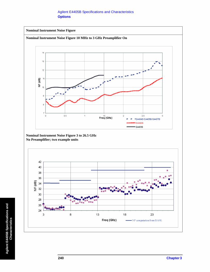
240 Chapter 3
Agilent E4405B Specifications and CharacteristicsOptions
Agi
lent
E44
05B
Spe
cific
atio
ns a
nd
Cha
ract
eris
tics
Nominal Instrument Noise Figure
Nominal Instrument Noise Figure 10 MHz to 3 GHz Preamplifier On
Nominal Instrument Noise Figure 3 to 26.5 GHzNo Preamplifier; two example units
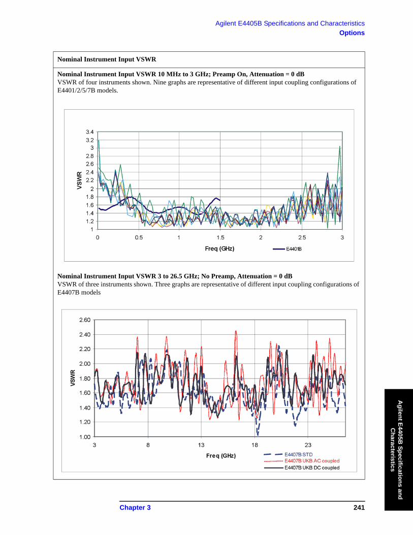
Chapter 3 241
Agilent E4405B Specifications and CharacteristicsOptions
Agilent E4405B
Specifications and C
haracteristics
Nominal Instrument Input VSWR
Nominal Instrument Input VSWR 10 MHz to 3 GHz; Preamp On, Attenuation = 0 dB VSWR of four instruments shown. Nine graphs are representative of different input coupling configurations of E4401/2/5/7B models.
Nominal Instrument Input VSWR 3 to 26.5 GHz; No Preamp, Attenuation = 0 dBVSWR of three instruments shown. Three graphs are representative of different input coupling configurations of E4407B models
242 Chapter 3
Agilent E4405B Specifications and CharacteristicsGeneral
Agi
lent
E44
05B
Spe
cific
atio
ns a
nd
Cha
ract
eris
tics
General
Specifications Supplemental Information
Temperature Range
Operating 0 to 55 °C Floppy disk 10 to 40 °C
Storage –40 to 75 °C
Specifications Supplemental Information
Altitude Range
Operating Up to 4600 meters
Specifications Supplemental Information
Humidity Range
Operating maximum relative humidity 80% for temperatures up to 31°C decreasing linearly to 50% relative humidity at 40°C
Specifications Supplemental Information
Audible Noise(ISO 7779)
Sound Pressure at 25 °C <40 dBa, (<4.6 Bels power)
Specifications Supplemental Information
Military Specification Has been type tested to the environmental specifications of MIL-PRF-28800F class 3.
Specifications Supplemental Information
EMI Compatibility Conducted and radiated emission is in compliance with CISPR Pub. 11/1990 Group 1 Class A.
(Option 060)a
a. Option 060 is not compatible with Option B7B nor Option 1DP.
Conducted and radiated emission is in compliance with CISPR Pub. 11/1990 Group 1 Class Bb.
b. Meets Class A performance during dc operation.
Chapter 3 243
Agilent E4405B Specifications and CharacteristicsGeneral
Agilent E4405B
Specifications and C
haracteristics
Specifications Supplemental Information
Immunity Testing
Radiated Immunity Testing was done at 3 V/m according to IEC 801-3/1984. When the analyzer tuned frequency is identical to the immunity test signal frequency, there may be signals of up to −60 dBm displayed on the screen.
Electrostatic Discharge Air discharges of up to 8 kV were applied according to IEC 801-2/1991. Discharges to center pins of any of the connectors may cause damage to the associated circuitry.
Specifications Supplemental Information
Acoustic Noise Emission/Geraeuschemission
LpA <70 dB
Operator position
Normal position
Per ISO 7779
LpA <70 dB
Am Arbeitsplatz
Normaler Betrieb
Nach DIN 45635 t.19
Specifications Supplemental Information
Power Requirements
ac Operation
Voltage, frequency 90 to 132 Vrms, 47 to 440 Hz
195 to 250 Vrms, 47 to 66 Hz
Power Consumption, On <300 W
Power Consumption, Standby <5 W
dc Operation
Voltage 12 to 20 Vdc
Power Consumption <200 W
Power Consumption, Standby <100 mW
Specifications Supplemental Information
Measurement Speed

244 Chapter 3
Agilent E4405B Specifications and CharacteristicsGeneral
Agi
lent
E44
05B
Spe
cific
atio
ns a
nd
Cha
ract
eris
tics
Local Measurement and Display Update ratea
Sweep points = 101 ≥ 40/s, characteristic
Sweep points = 401 ≥ 28/s, characteristic
Remote Measurement and GPIB Transfer Rateb,c
(Option A4H)
Sweep points = 101 ≥ 40/s, characteristic
Sweep points = 401 ≥ 28/s, characteristic
RF Center Frequency Tune, Measure, and GPIB Transfer Timec,d
(Option A4H)
Sweep points = 101 ≤ 75 ms, characteristic
Sweep points = 401 ≤ 90 ms, characteristic
a. Factory preset, auto align Off, segmented sweep Off, fixed center frequency, RBW = 1 MHz, fre-quency scale linear, spans >10 MHz and ≤600 MHz, and stop frequency ≤3 GHz.
b. Display Off (:DISPlay:ENABle OFF), and 32-bit integer data format (:FORMat:DATA INT,32), if Option AYX or A4J is installed, disable sweep ramp, (:SYSTem:PORTs: IFVSweep:ENABle OFF), markers Off, single sweep, measured with IBM compatible PC with 550 MHz Pentium® III running Windows® NT 4.0, one meter GPIB cable, National Instruments PCI-GPIB card and NI-488.2 DLL.
c. Factory preset, auto align Off, fixed center frequency, RBW = 1 MHz, frequency scale linear, and span = 20 MHz, fixed center frequency, stop frequency ≤3 GHz, average of 100 measurements.
d. Factory preset, auto align Off, segmented sweep Off, RBW = 1 MHz, frequency scale linear, span = 20 MHz, stop frequency ≤3 GHz, center frequency tune step size = 50 MHz.
Specifications Supplemental Information
Data Storage
Internala 8.0 MB, nominal
External(10 to 40 °C)
3.5" 1.44 MB, MS-DOS® compatible floppy disk
a. For serial numbers prior to US41440000 or MY41440000, 1 MB without Option B72, 8 MB with Option B72.
Specifications Supplemental Information
Memory Usage
State 20 kBa, nominal
Specifications Supplemental Information

Chapter 3 245
Agilent E4405B Specifications and CharacteristicsGeneral
Agilent E4405B
Specifications and C
haracteristics
State plus 401-point trace 21 kBa, nominal
Applications memory usageb
Distance to Fault (Option 225) 0.6 MB, nominal
Phase noise (Option 226) 1.1 MB, nominal
Cable TV (Option 227) 1 MB, nominal
Bluetooth (Option 228) 1.32 MB, nominal
Modulation Analysis (Option 229)
1.7 MB, nominal
HP 8566/68B Compatibility (Option 266)
0.24 MB, nominal
8590 Compatibility(Option 290)
0.7 MB, nominal
GSM (Option BAH) 3.2 MB, nominal
CDMA One (Option BAC) 2.8 MB, nominal
Noise Figure (Option 219) 1.6 MB, nominal
a. The size of state will increase depending on installed applications.b. Some applications may share files which may reduce total memory usage.
Specifications Supplemental Information
Demod Tune and Listen Internal speaker, front-panel earphone jack and front-panel volume control.
Demod AM
(Option BAA) Add FM
(Option A4J or AYX) An uncalibrated demodulated signal is available on the AUX VIDEO OUT connector at the rear panel.
(Option 106 or BAA) An uncalibrated demodulated signal is available on the EXT VIDEO OUT connector at the rear panel.
Specifications Supplemental Information
Weight (without options)
Net 17.1 kg (37.7 lb), characteristic
Specifications Supplemental Information

246 Chapter 3
Agilent E4405B Specifications and CharacteristicsGeneral
Agi
lent
E44
05B
Spe
cific
atio
ns a
nd
Cha
ract
eris
tics
Shipping 31.9 kg (70.3 lb), characteristic
Specifications Supplemental Information
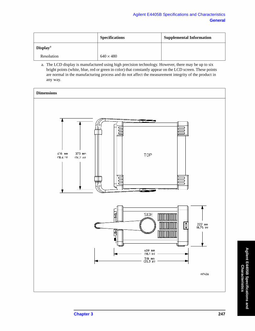
Chapter 3 247
Agilent E4405B Specifications and CharacteristicsGeneral
Agilent E4405B
Specifications and C
haracteristics
Specifications Supplemental Information
Displaya
Resolution 640 × 480
a. The LCD display is manufactured using high precision technology. However, there may be up to six bright points (white, blue, red or green in color) that constantly appear on the LCD screen. These points are normal in the manufacturing process and do not affect the measurement integrity of the product in any way.
Dimensions
248 Chapter 3
Agilent E4405B Specifications and CharacteristicsInputs and Outputs
Agi
lent
E44
05B
Spe
cific
atio
ns a
nd
Cha
ract
eris
tics
Inputs and Outputs
Front Panel
Specifications Supplemental Information
INPUT 50 Ω
Connector Type-N female
Impedance 50 Ω, nominal
Specifications Supplemental Information
RF OUT 50 Ω, (Option 1DN)
Connector Type-N female
Impedance 50 Ω, nominal
Specifications Supplemental Information
AMPTD REF OUTa Amplitude Reference
Connector BNC female
Impedance 50 Ω, nominal
Frequency 50 MHz
Frequency Accuracy Frequency reference errorb
50 Ω Amplitudec −20 dBm, nominal
a. Turn the amplitude reference on/off by pressing the keys: Input/Output, Amptd Ref Out.b. Frequency reference error = (aging rate × period of time since adjustment + settability + temperature
stability).c. The internal amplitude reference actual power is stored internally.
Chapter 3 249
Agilent E4405B Specifications and CharacteristicsInputs and Outputs
Agilent E4405B
Specifications and C
haracteristics
Specifications Supplemental Information
PROBE POWER
Voltage/Current +15 Vdc, ±7% at 150 mA max., characteristic
−12.6 Vdc ±10% at 150 mA max., characteristic
Specifications Supplemental Information
EXT KEYBOARDa Used for entering screen titles and filenames only. Interface compatible with most IBM-compatible PC keyboards.
Connector 6-pin mini-DIN
a. The feature is not implemented in firmware revisions prior to A.04.00.
Specifications Supplemental Information
Speaker Front panel knob controls volume
Specifications Supplemental Information
Headphone Front panel knob controls volume
Connector 3.5 mm (1/8 inch) miniature audio jack
Power Output 0.2 W into 4 Ω, characteristic
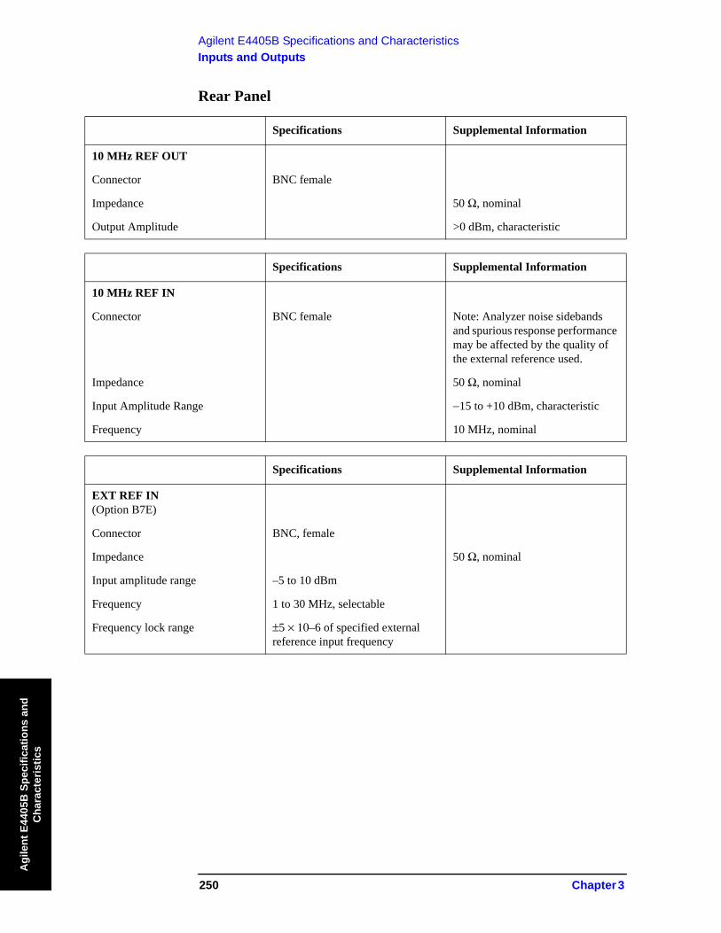
250 Chapter 3
Agilent E4405B Specifications and CharacteristicsInputs and Outputs
Agi
lent
E44
05B
Spe
cific
atio
ns a
nd
Cha
ract
eris
tics
Rear Panel
Specifications Supplemental Information
10 MHz REF OUT
Connector BNC female
Impedance 50 Ω, nominal
Output Amplitude >0 dBm, characteristic
Specifications Supplemental Information
10 MHz REF IN
Connector BNC female Note: Analyzer noise sidebands and spurious response performance may be affected by the quality of the external reference used.
Impedance 50 Ω, nominal
Input Amplitude Range −15 to +10 dBm, characteristic
Frequency 10 MHz, nominal
Specifications Supplemental Information
EXT REF IN(Option B7E)
Connector BNC, female
Impedance 50 Ω, nominal
Input amplitude range –5 to 10 dBm
Frequency 1 to 30 MHz, selectable
Frequency lock range ±5 × 10⁻⁶ of specified external reference input frequency

Chapter 3 251
Agilent E4405B Specifications and CharacteristicsInputs and Outputs
Agilent E4405B
Specifications and C
haracteristics
Specifications Supplemental Information
10 MHz OUT(Option B7E)
Connector BNC, female
Impedance 50 Ω, nominal
Frequency 10 MHz, nominal
Level 0 dBm when Option 10 MHz Out is On
Specifications Supplemental Information
GATE TRIG/EXT TRIG IN
Connector BNC female
External Trigger Input
Trigger Level Selectable positive or negative edge initiates sweep in EXT TRIG mode (5 V TTL)
Gate Trigger Input (Option 1D6)
Minimum Pulse Width >30 ns (5 V TTL)
Specifications Supplemental Information
GATE/HI SWP OUT
Connector BNC female
High Sweep Output
Level High = sweepa; Low = retrace (5 V TTL)
Gate Output (Option 1D6)
Level High = gate on; Low = gate off (5 V TTL)
a. High sweep may be high longer than the indicated sweep times.

252 Chapter 3
Agilent E4405B Specifications and CharacteristicsInputs and Outputs
Agi
lent
E44
05B
Spe
cific
atio
ns a
nd
Cha
ract
eris
tics
Specifications Supplemental Information
VGA OUTPUT
Connector VGA compatible, 15-pin mini D-SUB
Format VGA (31.5 kHz horizontal, 60 Hz vertical sync rates, non-interlaced) Analog RGB
Resolution 640 × 480
Specifications Supplemental Information
AUX IF OUT (Option A4J or AYX)
RBW ≥ 1 kHz
Connector BNC female
Frequency 21.4 MHz, nominal
Amplitude (for signal at reference level and for reference levels – input attenuation + preamp gain of –10 to –70 dBm)
−10 dBm (uncorrected), characteristic
Impedance 50 Ω, nominal
Specifications Supplemental Information
AUX VIDEO OUT (Option A4J or AYX)
RBW ≥ 1 kHz
Connector BNC female
Amplitude Range (into >10 kΩ) 0 to 1 V (uncorrected), characteristic
Specifications Supplemental Information
HI SWP IN(Option A4J or AYX)
Connector BNC female
Input Open collector, low resets and holds the sweep (5 V TTL)
Specifications Supplemental Information
HI SWP OUT(Option A4J or AYX)
Connector BNC female
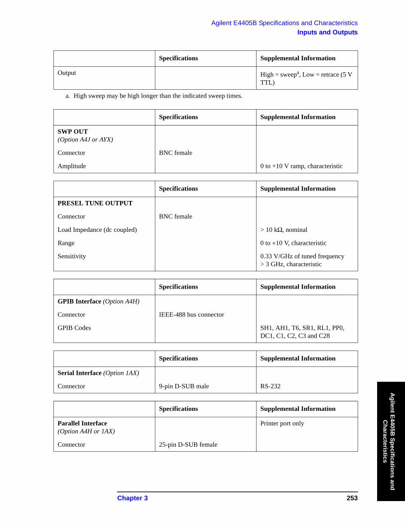
Chapter 3 253
Agilent E4405B Specifications and CharacteristicsInputs and Outputs
Agilent E4405B
Specifications and C
haracteristics
Output High = sweepa, Low = retrace (5 V TTL)
a. High sweep may be high longer than the indicated sweep times.
Specifications Supplemental Information
SWP OUT(Option A4J or AYX)
Connector BNC female
Amplitude 0 to +10 V ramp, characteristic
Specifications Supplemental Information
PRESEL TUNE OUTPUT
Connector BNC female
Load Impedance (dc coupled) > 10 kΩ, nominal
Range 0 to +10 V, characteristic
Sensitivity 0.33 V/GHz of tuned frequency > 3 GHz, characteristic
Specifications Supplemental Information
GPIB Interface (Option A4H)
Connector IEEE-488 bus connector
GPIB Codes SH1, AH1, T6, SR1, RL1, PP0, DC1, C1, C2, C3 and C28
Specifications Supplemental Information
Serial Interface (Option 1AX)
Connector 9-pin D-SUB male RS-232
Specifications Supplemental Information
Parallel Interface (Option A4H or 1AX)
Printer port only
Connector 25-pin D-SUB female
Specifications Supplemental Information

254 Chapter 3
Agilent E4405B Specifications and CharacteristicsInputs and Outputs
Agi
lent
E44
05B
Spe
cific
atio
ns a
nd
Cha
ract
eris
tics
Specifications Supplemental Information
EXT VIDEO IN/TV TRIG OUTa (Option B7B or BAA)
EXT VIDEO IN is the Baseband composite video input for TV trigger and picture on screen. TV TRIG OUT is the TV trigger output.
Connector BNC Female (75 Ω)
Impedance 75 Ω, nominal
(Option BAA without Option B7B) Feature not implemented
(Option BAA with Option B7B)External Video Input VideoAmplitude 1 Vp–p, nominal, characteristic
TV Trigger Output Positive edge indicates start of selected TV line after sync. pulse
Amplitude TTL (0 V and 3.4 V with 75 Ω series resistance), characteristic
a. This connector is labelled EXT VIDEO IN on older spectrum analyzers and EXT VIDEO IN/TV TRIG OUT on newer spectrum analyzers.

Chapter 3 255
Agilent E4405B Specifications and CharacteristicsInputs and Outputs
Agilent E4405B
Specifications and C
haracteristics
Specifications Supplemental Information
EXT VIDEO OUT Baseband video outputRBW ≥ 1 kHz
(Option B7B or BAA)
Connector BNC female (75 Ω)
Impedance 75 Ω, nominal
(Option BAA without Option B7B)
Amplitude 0 to 1 V (uncorrected), characteristic
(Option BAA with Option B7B)
Amplitude
TV Source: SA 0 to 1 V (uncorrected), characteristic
TV Source and EXTVIDEO IN
Same as level at EXT VIDEO IN/TV TRIG OUT, characteristic
(Option 106)
Connector BNC female (75 Ω)
Impedance 75 Ω, nominal
Amplitude 0 to 1 V (uncorrected), characteristic
Specifications Supplemental Information
EXT FRAME SYNC(Option B7D)
Connector BNC, female
Level 5 V TTL
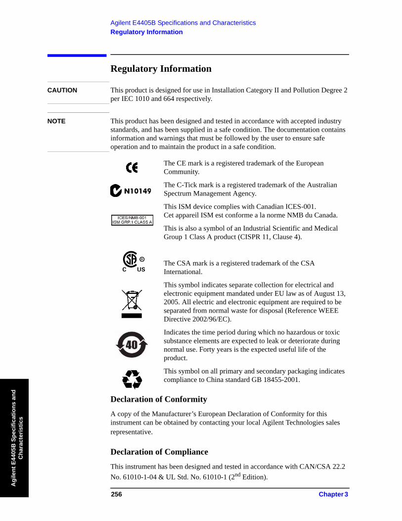
256 Chapter 3
Agilent E4405B Specifications and CharacteristicsRegulatory Information
Agi
lent
E44
05B
Spe
cific
atio
ns a
nd
Cha
ract
eris
tics
Regulatory Information
CAUTION This product is designed for use in Installation Category II and Pollution Degree 2 per IEC 1010 and 664 respectively.
NOTE This product has been designed and tested in accordance with accepted industry standards, and has been supplied in a safe condition. The documentation contains information and warnings that must be followed by the user to ensure safe operation and to maintain the product in a safe condition.
The CE mark is a registered trademark of the European Community.
The C-Tick mark is a registered trademark of the Australian Spectrum Management Agency.
This ISM device complies with Canadian ICES-001.Cet appareil ISM est conforme a la norme NMB du Canada.
This is also a symbol of an Industrial Scientific and Medical Group 1 Class A product (CISPR 11, Clause 4).
The CSA mark is a registered trademark of the CSA International.
This symbol indicates separate collection for electrical and electronic equipment mandated under EU law as of August 13, 2005. All electric and electronic equipment are required to be separated from normal waste for disposal (Reference WEEE Directive 2002/96/EC).
Indicates the time period during which no hazardous or toxic substance elements are expected to leak or deteriorate during normal use. Forty years is the expected useful life of the product.
This symbol on all primary and secondary packaging indicates compliance to China standard GB 18455-2001.
Declaration of Conformity
A copy of the Manufacturer’s European Declaration of Conformity for this instrument can be obtained by contacting your local Agilent Technologies sales representative.
Declaration of Compliance
This instrument has been designed and tested in accordance with CAN/CSA 22.2 No. 61010-1-04 & UL Std. No. 61010-1 (2nd Edition).