agilent 6890n, option 652 oral fluids analyzer · pdf fileagilent 6890n, option 652 oral...
TRANSCRIPT

Agilent 6890N, Option 652 Oral Fluids Analyzer
Installation and Operation
Agilent Technologies
Notices© Agilent Technologies, Inc. 2006
No part of this manual may be reproduced in any form or by any means (including elec-tronic storage and retrieval or translation into a foreign language) without prior agree-ment and written consent from Agilent Technologies, Inc. as governed by United States and international copyright laws.
Manual Part NumberG1540-90000
EditionFirst edition, November 2006
Printed in USA
Agilent Technologies, Inc. 2850 Centerville Road Wilmington, DE 19808-1610 USA
WarrantyThe material contained in this docu-ment is provided “as is”, and is sub-ject to being changed, without notice, in future editions. Further, to the max-imum extent permitted by applicable law, Agilent disclaims all warranties, either express or implied, with regard to this manual and any information contained herein, including but not limited to the implied warranties of merchantability and fitness for a par-ticular purpose. Agilent shall not be liable for errors or for incidental or consequential damages in connec-tion with the furnishing, use, or per-formance of this document or of any information contained herein. Should Agilent and the user have a separate written agreement with warranty terms covering the material in this document that conflict with these terms, the warranty terms in the sep-arate agreement shall control.
Safety Notices
CAUTION
A CAUTION notice denotes a haz-ard. It calls attention to an operat-ing procedure, practice, or the like that, if not correctly performed or adhered to, could result in damage to the product or loss of important data. Do not proceed beyond a CAUTION notice until the indicated conditions are fully understood and met.
WARNING
A WARNING notice denotes a hazard. It calls attention to an operating procedure, practice, or the like that, if not correctly per-formed or adhered to, could result in personal injury or death. Do not proceed beyond a WARNING notice until the indicated condi-tions are fully understood and met.
2 Oral Fluids Analyzer

In this Guide. . .
Oral Fluids Analyzer
This Installation and Operation Guide contains information for installing and using the Agilent 6890N, Option 652 Oral Fluids Analyzer (Analyzer). The Analyzer employs a Dean’s switching system intended for use with capillary columns and uses makeup gas to maintain adequate flow rates throughout the system.
1
SafetyThis chapter describes safety aspects for the Analyzer and its purpose.
2
IntroductionThis chapter describes general information for the Analyzer system.
3
Analyzer Installation, Checkout, and FamiliarizationThis chapter includes information with respect to Analyzer system installation and its checkout and familiarization.
4
MaintenanceThis chapter covers maintenance aspects for the Analyzer system.
5
AppendixA printed listing of all start-up eMethod setpoints is provided here.
Index
Keyword index and page numbers.
3

4
Oral Fluids Analyzer
Contents
1 Safety
Oral Fluids Analyzer
General Safety 7
2 Introduction
Analyzer Components 9
Overview 10
How It Works 14
3 Analyzer Installation, Checkout, and Familiarization
Installing the Analyzer System 18
Checkout, Verification, and Familiarization 20
Analyzing Your Own Samples 51
Post-Run and Column Backflushing 52
4 Maintenance
Column / Restrictor Tubing Replacement 59
5 Appendix
Analyzer eMethod Setpoints 67
Index
5

6
Oral Fluids Analyzer
Agilent 6890N, Option 652 Oral Fluids AnalyzerInstallation and Operation
1Safety
General Safety 7
General Safety
Many areas and parts of the GC operate at temperatures high enough to cause serious burns. These include, but are not limited to:
• Inside the oven, and components exposed within the oven:
• The inlet
• The detectors
• Any nut attaching a column to an inlet, to a detector, or to the Dean’s switch splitter plate and its metal tubing
• The JAS CryoTrap
Cool these areas to near room temperature before working on or around them.
The inlet and detector cool faster if you set their temperatures off and set oven temperature to room temperature (which keeps the oven fan and exhaust flaps in operation). Turn the oven off when room temperature is attained.
Also, be careful when working behind the instrument. During oven cooldown, the GC emits hot air exhaust from the oven which can cause burns.
If you must perform maintenance on hot parts, use a wrench and wear suitable gloves to avoid skin contact.
7Agilent Technologies

8
SafetyR
EV
IE
W
DR
AF
T
Oral Fluids Analyzer

Agilent 6890N, Option 652 Oral Fluids AnalyzerInstallation and Operation
2Introduction
Analyzer Components 9
Overview 10
How It Works 14
This chapter provides introductory information for your Analyzer.
Analyzer Components
The Analyzer system uses an Agilent 6890N gas chromatograph (GC) Factory-configured with the following required items:
• “Fast Oven” Option
• FID
• Split/Splitless capillary inlet
• Pneumatics control module (PCM)
• Dean’s switch
• The following Agilent columns and tubing:
• Primary column (DB-1ms, P/N 122-0112, 0.25-mm ID, 15-m length, 0.25-µm film thickness)
• Secondary column (DB-17ms, P/N 122-4712, 0.25-mm ID, 15-m length, 0.25-µm film thickness)
• FID Restrictor tube (deactivated fused silica, P/N 160-2635-1, 0.10-mm ID (0.36-mm OD), 1-m length as supplied). Length used in the Analyzer is described elsewhere (“FID Restrictor tube:" on page 60).
9Agilent Technologies
10
Introduction
• JAS Cryo Trap with Pressure Control Module (PCM)
• 7683B Automatic Liquid Sampler with tray
The Analyzer includes, as its second detector, a 5975N MSD which, in turn, includes a PC/controller with associated MS ChemStation software.
Overview
GC/MS with a quadrupole mass spectrometer is a widely used analytical technique. Its selectivity, sensitivity, cost effectiveness, and ability to use library searching for identification all have made this the instrument of choice for many years.
There are some samples however, where matrix interferences prevent sucessful analysis of desired analyte(s). For these, techniques like GC/MS/MS and LC/MS/MS have been used: greater selectivity afforded by a secondary mass spectral step overcomes interference problems.
For many analyses, especially those with a limited number of analytes (typically five or fewer), use of a two-dimensional (heart cutting) GC with a standard quadrupole MS can be a less complex and less expensive alternative. The two-dimensional (2-D) GC separation is used in place of a secondary mass spectrometric operation. Detection of drugs of abuse in oral fluids is a good example of where high-resolution 2-D GC/MS can be used.
The Agilent 6890N, Option 652 Oral Fluids Analyzer (Analyzer) is a two-dimensional (heart cutting) GC/MS system. Instrument configuration is a standard quadrupole GC/MS system to which a Deans switch and air-cooled focusing trap have been added.
Oral Fluids Analyzer

Introduction
Oral Fluids Analyzer
Referencing Figure 1, the primary GC column (“Column 1”) is a nonpolar DB-1ms and the secondary column (“Column 2”) is a polar DB-17ms:
1 Upon injection into the GC, analytes separate on the first column.
2 The Dean’s switch is time-programmed to heart cut the elution time range of the THC analyte from the first column onto the second column, where it is focused by the air-cooled “cryo” trap.
3 Upon thermal desorption in the second column, the analyte of interest is further separated from co-eluted matrix compounds from the first column. The cryo focusing trap improves both resolution and sensitivity.
4 At the end of analyte elution, carrier gas flow in the primary column is reversed to backflush unwanted heavy sample components out the inlet split vent thereby saving analysis time and reducing need for column trimming and replacement.
Note that, since only a small portion of the injected sample enters the MS ion source, source cleaning is reduced as well.
11

12
Introduction
7683Autosampler
6890NGC
.
The Analyzer’s oven interior is shown in Figure 2:
Figure 1 Hardware configuration, Analyzer system (restrictor not shown)
Cut
FID
Column 1
Deans switch
5975BInert MSD
FID
MSD
Focusing trap
Column 2
Oral Fluids Analyzer

Introduction
Oral Fluids Analyzer
S/S inlet
MSD
Cryotrap
Co(f
.
Figure 2 Oven interior, Analyzer system
FID
Dean’sswitch
lumn 1 Column 2
Restrictortubing
plate
ront) (rear)
13

Introduction
How It Works
14
S/26
Except at “cut” and “backflush” times, Analyzer gas flow configuration is as shown in Figure 3:
Based upon the state of the Dean’s switch solenoid valve, gas pressures from the inlet and Pressure Control Module (PCM), and pneumatic resistances of the columns and restrictor tubing, carrier flow from the inlet passes only to the FID. Thus, in this state, the Analyzer acts as a conventional single detector (FID) system capable of surveying all sample analytes over the course of an analysis. This mode allows location of the THC component of interest amongst sample matrix interferences of no interest.
During the predetermined “cut” time when (hopefully) the THC component of interest is diverted to the MSD, the Analyzer gas flow configuration is as shown in Figure 4:
Figure 3 “No cut” configuration (cryo focusing trap not shown)
FID
S Inlet PCM
Solenoid valve (off)Restrictor
DB-1 ms
DB-17 ms
.59 psig 19.60 psig
MSD
Oral Fluids Analyzer

Introduction
Oral Fluids Analyzer
In26
Here with the solenoid valve switched to its alternate position, Dean’s switch flows are reversed such that now the MSD is the “single” detector receiving the THC component of interest via a cryo (coolant air) focussing step and a second column (“Column 2”, Figure 1). The FID receives no sample components during this time.
At the defined end of the cut time, the Analyzer returns to its “no cut” configuration (Figure 3).
After the analytical portion of the run ends, the Analyzer enters into a “backflushing” gas flow configuration (Figure 5):
Figure 4 “Cut” configuration (cryo focusing trap not shown)
FID
jector PCM
Solenoid valve (on)Restrictor
DB-1 ms
DB-17 ms
.59 psig 19.60 psig
MSD
15

16
Introduction
S/S 26.59 psig
With respect to the Dean’s switch valve state, this mode is the same as the “no cut” state. However, inlet and PCM pressures are automatically changed such that a low flow rate of gas is allowed to flow backwards through “Column 1” (Figure 1) into the inlet where it is then swept out the split vent. This has the beneficial effect of flushing out low-volatility materials of no analytical interest from the head of the primary column.
Note that no similar treatment is needed for the secondary column (“Column 2”) as it “sees” only the THC component of interest and therefore cannot accumulate other component materials of no interest.
Figure 5 “Backflush” configuration (cryo focusing trap not shown)
FID
Inlet PCM
Solenoid valve (off)Restrictor
DB-17 ms
DB-1 ms
to 1 psig 19.60 psig to 65 psi
MS
For more information
For detail regarding this application see the application note by Dean F. Fritch and Bruce D. Quimby*, “Confirmation of THC in Oral Fluids Using High-Resolution 2-D GC/MS”, publication 5989-5668EN.pdf, provided on the “Specials Factory Information” CD accompanying the Analyzer in the folder <drive>:\AnalyzerDocumentation\ .
Oral Fluids Analyzer

Agilent 6890N, Option 652 Oral Fluids AnalyzerInstallation and Operation
3Analyzer Installation, Checkout, and Familiarization
Installing the Analyzer System 18
Connection, GC Cryo Trap Coolant Air 19
Checkout, Verification, and Familiarization 20
Analyzing Your Own Samples 51
Post-Run and Column Backflushing 52
This chapter contains instructions and procedures both for installing the Analyzer, and for its subsequent checkout and operational verification. Checkout and verification procedures described here are also of use when changes (for example, a column change) are made to the Analyzer.
17Agilent Technologies

Analyzer Installation, Checkout, and Familiarization
Installing the Analyzer System
18
WARNING To avoid shock hazard, make sure power switchs are off and line power cords disconnected before continuing.
The Analyzer consists of three main components: a 5975N Mass Selective Detector (MSD) system, a Factory-configured 6890N Gas Chromatograph (GC), and 7683B Automatic Liquid Sampler (ALS) with tray.
• For the GC/MSD system, follow site preparation and installation procedures as per supplied documentation. The column end to connect to the MSD is found within the GC oven complete with preswaged nut and ferrule.
WARNING Hydrogen gas is flammable and potentially explosive when accumulated inside the oven. For this reason, Hydrogen should not be used as carrier gas with this product due to possibility of tube breakage.
• For the GC:
• In the normal manner, connect Helium as carrier gas to the inlet, and Hydrogen, Air, and, as make-up gas, Helium or Nitrogen to the FID
• Also connect Helium to the JAS Cryo Trap PCM
• Connect a suitable air supply to the Factory-installed JAS Cryo Trap air inlet fitting (see “Connection, GC Cryo Trap Coolant Air" on page 19)
• Your GC requires a stable AC power source to insure rapid, controlled oven heating rates required by this application. Make sure your AC power source is capable of maintaining it voltage at the full rated Wattage specified for the GC. Also make sure rated voltage of your AC power source matches that required by the GC.
Oral Fluids Analyzer
Analyzer Installation, Checkout, and Familiarization
Oral Fluids Analyzer
• For the ALS, follow site preparation and installation procedures as per its supplied documentation.
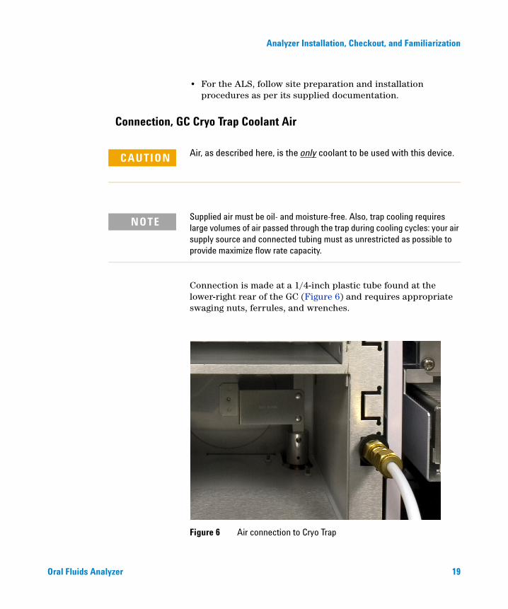
Connection, GC Cryo Trap Coolant Air
CAUTION Air, as described here, is the only coolant to be used with this device.
NOTE Supplied air must be oil- and moisture-free. Also, trap cooling requires large volumes of air passed through the trap during cooling cycles: your air supply source and connected tubing must as unrestricted as possible to provide maximize flow rate capacity.
Connection is made at a 1/4-inch plastic tube found at the lower-right rear of the GC (Figure 6) and requires appropriate swaging nuts, ferrules, and wrenches.
Figure 6 Air connection to Cryo Trap
19

20
Analyzer Installation, Checkout, and Familiarization
Once connected, set air pressure to 100 psig (689.5 kPa) {minimum of 40 psig (276 kPa)}.
This completes Analyzer system installation.
Checkout, Verification, and Familiarization
This section provides procedures to validate proper Analyzer operation. In so doing, these procedures also provide you with application familiarization.
It is presumed you already have good working knowledge of the individual Analyzer components: the GC, the MSD, and the ALS. If not, consult their documentation as needed.
Establishing Parameters
NOTE Before proceding, make sure the MSD is leak-free by verifying that it meets ambient atmospheric H2O and/or air limits, and has been successfully tuned. If necessary, troubleshoot and resolve any MSD performance issues before continuing.
Whether you are doing this checkout for the first time, or doing it because of a system change possibly affecting the chromatography (for example, a column change), the following procedure is intended to both set up your system and to provide Analyzer familiarization.
Initialization
This section is typically necessary only for first-time setup and use.
1 A MSD “eMethod”, OFA_THC_Base.emeth, is provided on the “Specials Factory Information” CD accompanying the Analyzer in the folder <drive>:\eMethod\ . Follow MS ChemStation procedures to load the eMethod. Then allow sufficient time for the entire system to stabilize. During
Oral Fluids Analyzer

Analyzer Installation, Checkout, and Familiarization
Oral Fluids Analyzer
stabilization, you may continue with steps through step 5 on page 31 of “Analysis using the FID only”:
a There are a few ALS configuration parameters, not included in the eMethod, which must be entered manually through the GC keypad. Consult your ALS user documentation as needed to set wash mode to Use A-A2, B-B2. Also set Solvent Saving to 1.0µL.
b Select menu items Instrument > MS SIM/Scan Parameters… to open the following dialogs to verify MSD SIM parameters against those seen in Figure 7, Figure 8, and Figure 9. Note the generous Solvent Delay value (5.00 min.) provided to insure the MS source remains off until shortly before the THC component peak is expected.
c Select the Edit SIM Params button to check additional parameters.
d If necessary, make changes to these dialog views and select OK to close the dialogs. If no changes are made, close with Cancel instead:
21

22
Analyzer Installation, Checkout, and Familiarization
Figure 7 Verifying / Editing MS SIM Parameters
Oral Fluids Analyzer

Analyzer Installation, Checkout, and Familiarization
Oral Fluids Analyzer
Figure 8 Editing MS SIM parameters (1 of 2)
23

24
Analyzer Installation, Checkout, and Familiarization
Figure 9 Editing MS SIM parameters (2 of 2)
Oral Fluids Analyzer

Analyzer Installation, Checkout, and Familiarization
Oral Fluids Analyzer
e If desired, print the method and compare it to the printed version of the same method provided in the Appendix of this document.
f Save the method under a name of your choosing, for example as ‘StartUpCheckout-THC’. We will save versions of this method separately under new names as we work along to preserve history of this process.
g Note the presentation of the upper half of the Instrument Control window. It should appear similar to that shown in Figure 10:
Figure 10 Instrument Control window, upper half
Dean’s switch status
Trap temp.
Trap press.
• If not already enabled and positioned, use menu items Instrument > GC Monitors… and MS Monitors… to enable the various status monitors. They can then be dragged to desired locations.
• Items labeled “Trap press.”, “Trap temp.”, and “Dean’s switch status” are important during analyses in that they indicate actions occurring during the “heart cut” portion of each given run when the THC component is diverted from the FID to the trap and MSD.
25

26
Analyzer Installation, Checkout, and Familiarization
2 The lower portion of the presentation shows two signal views at this time, specifically for the GC FID, and the other specifically for the MSD signal.
Analysis using the FID only
We must have a complete chromatogram such that the THC component peak can then be located. Once located, the peak allows choosing appropriate “cut” times for subsequent analyses of your actual samples.
1 At this time, we need analyze only the FID signal, so the MS signal at this time should be switched ‘Off’. Select menu items Instrument > Inlet/Injection Types… to open the following dialog (Figure 11):
Verify the Use MS checkbox is UNchecked: if checked, uncheck it as shown and close the dialog by selecting OK.
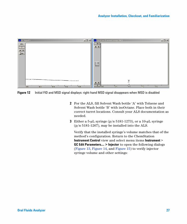
At this time, the MSD signal view disappears from the lower portion of the window thereby leaving only the FID signal view (Figure 12):
Figure 11 Disable the MSD
Oral Fluids Analyzer
Analyzer Installation, Checkout, and Familiarization
Oral Fluids Analyzer
Figure 12 Initial FID and MSD signal displays: right-hand MSD signal disappears when MSD is disabled
2 For the ALS, fill Solvent Wash bottle ‘A’ with Toluene and Solvent Wash bottle ‘B’ with isoOctane. Place both in their correct turret locations. Consult your ALS documentation as needed.
3 Either a 5-µL syringe (p/n 5181-1273), or a 10-µL syringe (p/n 5181-1267), may be installed into the ALS.
Verify that the installed syringe’s volume matches that of the method’s configuration. Return to the ChemStation Instrument Control view and select menu items Instrument > GC Edit Parameters… > Injector to open the following dialogs (Figure 13, Figure 14, and Figure 15) to verify injector syringe volume and other settings:
27

28
Analyzer Installation, Checkout, and Familiarization
Figure 13 Verifying / Editing GC Injector parameters
Oral Fluids Analyzer

Analyzer Installation, Checkout, and Familiarization
Oral Fluids Analyzer
Figure 14 Configuring injector syringe size
29

30
Analyzer Installation, Checkout, and Familiarization
Figure 15 More injector configuration parameters
Consult your ALS documentation as needed.
4 Locate the derivatized THC test sample kit, “Sample - THC” (p/n G1540-85010, 1 ampoule/pkg., 1 µg/mL derivatized THC
Oral Fluids Analyzer

Analyzer Installation, Checkout, and Familiarization
Oral Fluids Analyzer
in isoOctane, and 50 µg/mL N,O-Bis(trimethylsilyl) trifluoroacetamide {BSTFA} added as stabilizer).
a Prepare the THC checkout sample by breaking the ampoule and transferring its contents to a suitable screw-top (with septum) ALS sample vial.
b Place the vial into the #1 sample location in the ALS tray.
c When finished with the sample, replace the screw-top with a new one. In this state, the sample may be kept refrigeratored for up to a year for reuse as needed.
5 Prepare for a manually started analysis via menu items Method > Run Method… which opens the following dialog (Figure 16):
Figure 16 Manual run control
31
32
Analyzer Installation, Checkout, and Familiarization
• Items marked with an asterisk, ‘ * ‘, should be completed with unique definitions such that you can keep track of this particular analyis whose purpose is to determine check-out sample cut time for its THC component. Items marked with a cross-hatch, ‘ # ‘, are optional but recommended.
• For Method Sections To Run:, UNcheck Data Analysis to avoid printing of large amounts of unnecessary paper.
6 When ready, select Run Method to perform the analysis.
Determine the cut time
Upon completion of the analysis, start MS ChemStation Enhanced Data Analysis and load the just-completed analysis data ( ‘.D’).
The THC component peak should be found at a run time region of about 5-to-6 minutes. It is quite small and requires multiple ‘zoom’ steps to make it visible. Zoom as needed to display approximately the lower half of the peak (Figure 17):
Oral Fluids Analyzer

Analyzer Installation, Checkout, and Familiarization
Oral Fluids Analyzer
Figure 17 Zoomed THC peak (approximately 1/2-height) from FID and chosen cut times
From your display, with only a little generosity at the beginning and end of the peak, choose start and end cut times such that the entire THC component will be diverted without risk of either “clipping” the THC component peak, or including other neighboring components possibly present in your real samples.
From this example, we chose 5.56 minutes to start the cut, and 5.67 minutes to end it. We will use these values in subsequent steps.
33

34
Analyzer Installation, Checkout, and Familiarization
NOTE Because a correct cut time is so critical to method success, you may want to repeat this process multiple times to come up with an average “best” cut times.
Enter cut times into the method
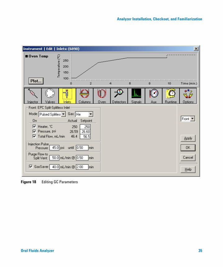
Return to the ChemStation Instrument Control view and select menu items Instrument > GC Edit Parameters… to open the following dialog (Figure 18):
Oral Fluids Analyzer
Analyzer Installation, Checkout, and Familiarization
Oral Fluids Analyzer
Figure 18 Editing GC Parameters
35

36
Analyzer Installation, Checkout, and Familiarization
1 The Dean’s switch valve is assigned as Valve #1. Verify this by selecting the Valves icon (Figure 19):
Figure 19 Verifying the Dean’s switch valve
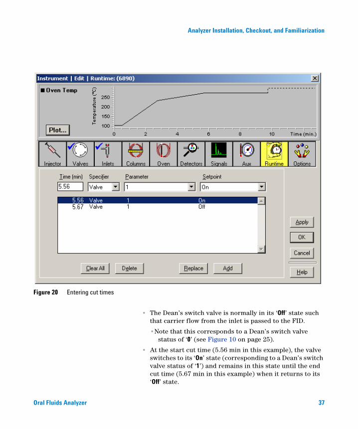
2 Select the Runtime icon to enter start and end cut times as runtime valve events (Figure 20):
Oral Fluids Analyzer
Analyzer Installation, Checkout, and Familiarization
Oral Fluids Analyzer
Figure 20 Entering cut times
• The Dean’s switch valve is normally in its ‘Off’ state such that carrier flow from the inlet is passed to the FID.
•Note that this corresponds to a Dean’s switch valve status of ‘0’ (see Figure 10 on page 25).
• At the start cut time (5.56 min in this example), the valve switches to its ‘On’ state (corresponding to a Dean’s switch valve status of ‘1’) and remains in this state until the end cut time (5.67 min in this example) when it returns to its ‘Off’ state.
37

38
Analyzer Installation, Checkout, and Familiarization
During the cut time period, carrier flow is diverted to the cryo trap and on to the MSD.
Determine your cryo trap temperature program times
Trap timing is based upon your chosen cut times (in turn based upon the THC component peak’s elution time) and must:
• Allow sufficient time for the trap to cool and stabilize as quickly as possible from its normal temperature of 300 °C to its trapping temperature of 100 °C
• Encompass your chosen cut time to trap only the THC component
• Then return as quickly as possible to 300 °C to release the THC component for analysis by the MSD
Trapping times, in coordination with cut times, are critical to success of the method. By way of example, what follows is a relatively conservative process, based upon our previously-chosen cut times (“Determine the cut time" on page 32 and Figure 17). The process begins by understanding what we wish to accomplish (Figure 21):
Oral Fluids Analyzer

Analyzer Installation, Checkout, and Familiarization
Oral Fluids Analyzer
Figure 21 Determining your trap timing relative to your chosen cut times
Start trap cooling 2 minutes before the start cut time
Stop trap cooling 0.2 minutes after the stop cut time
– 2 min + 0.2 min
To do this, trap temperatures and times are managed as follows:
• The trap is cooled from 300 °C as quickly as possible (800 °C/min) to 100 °C at 3.56 min (5.56 – 2.00 min)
• Cooling from 300 °C to 100 °C at 800 °C/min requires 0.25 min, so the trap is at 100 °C at 3.81 min (3.56 + 0.25 min)
• The trap is reheated to 300 °C at 5.87 min (5.67 + 0.20 min)
39

40
Analyzer Installation, Checkout, and Familiarization
• So trap “hold” time at the reduced temperature of 100 °C is determined to be 2.06 min (5.87 – 3.81 min)
• Note that “hold” time for the trap reheated to 300 °C is then intentionally set to continue past the end of the analysis
The entire process is summarized in the following timing diagram (Figure 22):
Figure 22 Trap temperature timing relative to THC component peak and chosen cut times
Oral Fluids Analyzer

Analyzer Installation, Checkout, and Familiarization
Oral Fluids Analyzer
The seemingly lengthy period of time prior to the cut start time, during which the trap is at 100 °C, is intentional to insure the trap is truly stable at 100 °C. Through experimentation, you may find that you can start trap cooldown later in time (which affects your trap hold time at 100 °C).
41

42
Analyzer Installation, Checkout, and Familiarization
Enter your determined cryo trap temperature program times
To enter your determined trap parameters:
1 Select the Inlets icon (Figure 23). If needed, then select the Back inlet:
Figure 23 Entering trapping times
2 Enter your trap temperature program parameters into their respective table locations.
Oral Fluids Analyzer

Analyzer Installation, Checkout, and Familiarization
Oral Fluids Analyzer
3 Optionally, if desired, select the Plot button in the upper left portion of the dialog to open a second dialog to select item(s) to be plotted in the upper portion of the main dialog box (Figure 24):
To see an overlayed profile of trap and oven temperature programs, select Back Inlet Temperature, then OK. The resultant overlay appears as in Figure 25 and is a convenient visual reminder of the two temperature programs occurring during the analysis:
Figure 24 Plot selection items
43

44
Analyzer Installation, Checkout, and Familiarization
Figure 25 Overlayed oven and trap temperature profiles
This completes entry of GC parameters for the analysis. Close GC Edit Parameters… dialog by selecting OK.
Enable the MSD
1 Select menu items Instrument > Inlet/Injection Types… to open the following dialog (Figure 26):
2 Check the Use MS checkbox as shown and close the dialog by selecting OK.
Figure 26 Enable the MSD
Oral Fluids Analyzer

Analyzer Installation, Checkout, and Familiarization
Oral Fluids Analyzer
Monitoring your system during analyses
In principle, we are now ready to perform analysis of the checkout sample. However, before doing so, there are certain items you will want to monitor during this analysis, and perhaps later analyses as well, to maintain confidence (or not) in system behavior. Items listed can affect run-to-run reproducibility:
GC ‘Ready’ness indicators
At the GC during the analysis, monitor its status, particularly the LED indicating oven ramp Rate status (Figure 27). Consult your 6890N user documentation for more detail regarding other status indicators and their meanings:
The oven must follow a very agressive temperature change rate during an analysis: if the Ramp indicator flashes 4 or more times during an analysis, actual oven temperature is no longer accurately tracking the oven controller’s calculated temperature. This may be due to AC power source capacity unable to keep up with oven heater demand.
Trap status indicators
From Figure 10 on page 25, note that you can monitor trap status at any time via the following GC monitors (Figure 28):
Figure 27 6890N Status board
Oven Ramp
PreRun Initial
Temp
FinalTemp
PostRun
NotReady
Run
Remote ClockTable
Gas SaverFront
Back
RunLog
Rate
45

46
Analyzer Installation, Checkout, and Familiarization
Pay particular attention to the run time specified at which the trap is to cool from 300 °C to 100 °C: the trap must be at 100 °C by just before your start cut time. If attainment of 100 °C is delayed, this adversely affects trapping of the THC component.
If the trap falls behind in its cooling rate, this may be due to insufficient cooling air through the trap, and/or incoming coolant air is being warmed in some way outside the GC.
If necessary, you may need to compensate by adjusting time at which trap cooling occurs, and/or by adjusting cooling air flow rate.
Cut time indicator
Status of Dean’s switch valve (Figure 29) is available via another GC monitor (reference Figure 10 on page 25):
The switch state reflects your chosen cut times:
• The state is normally ‘0’ (zero), ‘OFF’, such that carrier flow passes to the FID
• At your cut start time, the state becomes ‘1’, ‘ON’, such that carrier flow diverts to the trap and MSD
• At your cut end time, the state returns to ‘0’ (zero), ‘OFF’
Figure 28 Trap status monitors
Figure 29 Dean’s switch status monitor
Oral Fluids Analyzer

Analyzer Installation, Checkout, and Familiarization
Oral Fluids Analyzer
Total elapsed time for this, though brief (using our example cut times, it is 5.67 – 5.56 min or 0.11 min), is just long enough to provide visual verification that switching occurs at your chosen run times.
Chromatographic indicators
During an analysis, two chromatogaphic plot windows display, respectively, FID and MSD signals (Figure 30):
Figure 30 FID and MS chromatographic plots (cut time ok)
The small negative signal excursion at about 5.5 min on the left-hand FID plot is the heart cut event during which carrier flow is diverted to the MSD. The right-hand MSD plot shows the diverted THC component peak. Note the time-scale difference between the two plots: the THC peak shows up later on the MSD plot than the cut time on the FID plot due to its being additionally retained on the secondary column.
The FID plot, in particular, is a sensitive visual indicator of the success of your chosen cut times. Here are two plot sets showing slightly misplaced cut times (Figure 31 and Figure 32):
47

48
Analyzer Installation, Checkout, and Familiarization
Figure 31 FID and MS chromatographic plots (trap time too early)
• In this case (Figure 31), cut end time occurs before all of the THC component peak has been diverted. What is not diverted is seen in the FID signal. As a secondary effect, area counts for the THC component as measured by the MSD are reduced.
Figure 32 FID and MS chromatographic plots (cut time too late)
Oral Fluids Analyzer
Analyzer Installation, Checkout, and Familiarization
Oral Fluids Analyzer
• In this case (Figure 32), cut start time occurs after some of the THC component peak has gone to the FID and is seen in the FID signal. Again, as a secondary effect, area counts for the THC component as measured by the MSD are reduced.
This problem is not just one of initially mis-choosing cut times: over time your system may drift (column aging, for example) or may shift (trimming a piece of column off, or changing a column, for example). As part of method maintenance then:
• Expect to revisit your cut times and make adjustments as needed
• In so doing, do not forget that your associated trap times also may need adjustment
Save the Method
With all necessary parameter and display information now entered, this is your working method for use with the checkout sample. Save it as a new name of your choosing so you can come back to it as needed.
Perform the checkout analysis
Prepare for a manually started analysis via menu items Method > Run Method… which opens dialog previously seen in Figure 16 on page 31. Enter any desired information.
When ready, select Run Method to perform the analysis.
After analysis completion, load its datafile into Enhanced Data Analysis to view results. As a typical example, see Figure 33:
49

50
Analyzer Installation, Checkout, and Familiarization
Figure 33 Typical THC checkout results
Note the following:
• Due to MS tuning and/or other factors affecting MS response, your resultant THC peak may not be of the same abundance as shown here
• The FID baseline signal (lower view) is intentionally greatly ‘zoomed’ to show the cut event
• Time displacement between the cut event and the observed THC peak is additional time for the THC component to move through the secondary column (Column 2)
Oral Fluids Analyzer

Analyzer Installation, Checkout, and Familiarization
Oral Fluids Analyzer
• No quantitative results are possible at this time as no calibration table presently exists
Analyzing Your Own Samples
Now that you have successfully familiarized yourself with Analyzer operation in running the supplied checkout sample you must repeat this entire process using your own standard prepared in the same way as samples you intend to analyze. This ensures cut and trap times are appropriate for your samples and their specific preparation processes.
As part of your process, you must create a calibration table to be used in providing quantitative results for your samples.
51

Analyzer Installation, Checkout, and Familiarization
Post-Run and Column Backflushing
52
From the supplied eMethod, the analysis portion of the run ends at 9.72 min and a 3-minute post run portion begins (Figure 34):
Figure 34 Oven temperature profile
During this time period, backflushing occurs on the primary column as an automated preventive maintenance process. 3 minutes is chosen as the time period based upon wanting a minimum of 5 “void times” (“holdup times”) through Column 1 (reference Figure 1 on page 12) to ensure optimal removal of undesired components at the head of the column.
Background
One way to significantly reduce cycle times in GC analysis is to backflush late-eluting compounds from the column. “Backflush” is a term used for reversal of gas flow through a column such that sample components in the column are forced backwards out of the inlet end of the column.
Where backflushing provides greatest benefits include:
• Methods where sample components of interest elute early, but a longer temperature ramp is required to remove later-eluting components from the column
• Methods where high-boiling matrix components contaminate the column requiring frequent maintenance, for example by trimming the head of the column
Oral Fluids Analyzer

Analyzer Installation, Checkout, and Familiarization
Oral Fluids Analyzer
Backflushing is also beneficial in that:
• Cycle times (total time to run a sample and then become ready to run the next sample) are improved:
• Both run and cool down times are reduced resulting in gained efficiencies and reduced data file sizes
• Data quality is improved:
• Column bleed is reduced (less exposure to high temperatures)
• Ghost peaks (carryover into subsequent runs) are eliminated
• Column lifetime is increased since:
• High-boiling components do not accumulate on the column
• The column is spared exposure to high bakeout temperatures
• Calibrations and system suitability are maintained for longer periods
• For a connected MSD, its source is not exposed to high-boiling components leading to:
• Less source cleaning
• Longer periods between tunes
• Columns may be conditioned in backflush mode to prevent MSD source contamination
• Electrical power is saved:
• Lower maximum GC temperature
• Less time spent by the GC at high temperature
• Less air conditioning power required to offset reduced heat output from the GC
• Less gas is used:
• Less time per sample requires less carrier gas per sample
Post Run Backflushing
An automated Post Run backflushing program, as used in this application, provides several advantages:
53

54
Analyzer Installation, Checkout, and Familiarization
• Data acquisition automatically terminates (the MSD source and detector are switched OFF, thereby protecting the source during the process)
• Pressure changes are ballistic (as fast as they can be established) rather than at the 99.99 psi/min maximum controlled inlet pressure program rate.
• Changes can be made to the analytical part of the method (involving, for example, pressures, temperatures, times, and ramps) without needing to change Post Run backflush setpoints.
• Post Run conditions are executed even if a run is stopped. Runs which are stopped will have remaining components backflushed, thereby quickly and effectively readying the column for subsequent use.
Post Run Backflushing Parameters
Set up for Post Run backflushing in this application’s method involves parameters provided in three dialog views (Figure 35, Figure 36, and Figure 37):
Oral Fluids Analyzer
Analyzer Installation, Checkout, and Familiarization
Oral Fluids Analyzer
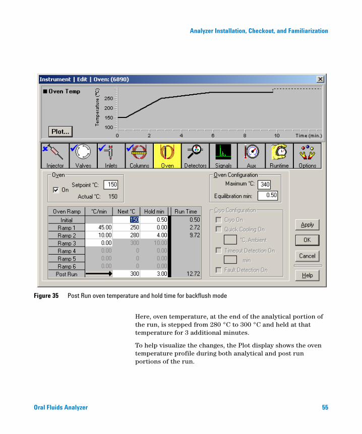
Figure 35 Post Run oven temperature and hold time for backflush mode
Here, oven temperature, at the end of the analytical portion of the run, is stepped from 280 °C to 300 °C and held at that temperature for 3 additional minutes.
To help visualize the changes, the Plot display shows the oven temperature profile during both analytical and post run portions of the run.
55

56
Analyzer Installation, Checkout, and Familiarization
Figure 36 Post Run Column 1 pressure change for backflush mode
During this 3 minute post run time period, Column 1 head pressure at the Split/Splitless inlet is reduced to, and held at, 1 psi, thereby allowing gas flow from the Dean’s switch to flow backwards to flush contaminants from the head of Column 1.
The Plot display now shows Column 1 pressure and flow rate changes during both analytical and post run portions of the run.
Oral Fluids Analyzer

Analyzer Installation, Checkout, and Familiarization
Oral Fluids Analyzer
Figure 37 Post Run Column 2 pressure change for backflush mode
Also, during this 3 minute post run time period, Column 2 head pressure from the Dean’s switch PCM (Figure 5 on page 16) is raised to, and held at, 65 psi, to cause gas flow from the Dean’s switch to flow backwards to flush contaminants from the head of Column 1.
The Plot display now shows Column 2 pressure and flow rate changes during both analytical and post run portions of the run.
57

58
Analyzer Installation, Checkout, and Familiarization
Note that your MS vacuum pumping system must be capable of maintaining an ion gauge pressure reading of 10-3 torr or less during post run backflushing when Column 2 flow rate is dramatically increased. From a practical point of view, this eliminates diffusion systems: only turbopumping systems have sufficient capacity.
For more information
For detail regarding post run automated backflushing, especially if you make modifications to this Analyzer, see the application note by Matthew S. Klee, “Simplified Backflush Using Agilent 6890 GC Post Run Command”, publication 5989-5111EN.pdf, provided on the “Specials Factory Information” CD accompanying the Analyzer in the folder <drive>:\AnalyzerDocumentation\ .
Oral Fluids Analyzer

Agilent 6890N, Option 652 Oral Fluids AnalyzerInstallation and Operation
4Maintenance
Column / Restrictor Tubing Replacement 59
This chapter discusses maintenance information for your Analyzer.
Column / Restrictor Tubing Replacement
Over time, it may become necessary to replace Analyzer primary and/or secondary columns, and/or the FID restrictor tubing. Of these, the forward primary column (“Column 1”) is the most likely to need replacement as it receives the entire sample at every injection.
Begin by reviewing general oven components involved in the process of replacing a column (Figure 2 on page 13). Then also note the following Table (Table 1), and detailed views (Figure 38 and Figure 39):
59Agilent Technologies

60
Maintenance
Table 1 Column and restrictor tube routing
Item End 1 End 2
Column 1: (forward column)
S/S inlet Dean’s switch plate middle fitting
Column 2: (rearward column)
Pass the column through the cryo trap, from bottom to top, then on to the Dean’s switch plate top fitting
MSD
FID Restrictor tube:
Dean’s switch plate bottom fitting
Note that Restrictor tube length is critical: it must be 31.2 ±0.1 cm in length after trimming and ends preparation
FID
Tubing ends to the MSD, and to the GC’s inlet and FID, are prepared and installed normally: see their respective documentation sources for proper procedures.
General information and procedure for column and restrictor ends installed into the Dean’s switch plate is provided here.
Oral Fluids Analyzer

Maintenance
Oral Fluids Analyzer
Figure 38 Routing Column 2 through the cryo trap
S/Sinlet
toMSD
Cryotrap
Columndirection
Columnclip(1 of 4)
61

62
Maintenance
Figure 39 Detail, Dean’s switch connections
Column 2
Column 1
FIDrestrictortube
Dean’sswitchplate
Disconnecting existing tubing from the Dean’s switch assembly
Where needed, loosen and remove the nut from the Dean’s switch assembly fitting. Usually the tubing and its ferrule will fall out of the fitting.
Oral Fluids Analyzer

Maintenance
Oral Fluids Analyzer
Occasionally the ferrule will stick inside the fitting. If this happens, use a pointed object such as a pen or paper clip end and insert it into the ferrule release ejector hole in the side of the fitting (Figure 40). Press firmly: the ferrule will audibly ‘click’ when it breaks free.
Figure 40 Releasing a ferrule
Ejectorhole
Paper clip
Protect disconnected column and restrictor tubing
Column and restrictor tubes with swaged metal ferrules can be disconnected and reconnected several times. To protect the nut and tubing end, use a brass-sealing cap (p/n G2855-20590). Tighten to finger-tight plus 15 degree.
Protect the Dean’s switch assembly
Seal port(s) of the Dean’s switch assembly with plugs when nothing is connected to keep particulates and contamination out.
To make a plug, cut about 2 inches (5 cm) of stainless steel wire and swage it as you would a column. Use a metal ferrule sized for 0.25-mm id columns. After swaging, cut excess wire to
63

64
Maintenance
within 0.5 mm of the ferrule end with a small, high-quality, wire cutter. Leave exposed wire outside the nut to serve as a “handle” in removing the plug.
Replacing Column(s) and/or FID Restrictor
1 If replacing one or both columns, clip column baskets together using basket hooks.
As needed, center the column assembly in the oven. As needed, adjust and tighten column clips so the column assembly is tightly held to the oven shroud.
2 For detailed instructions in preswaging an internal nut and SilTite ferrule onto the end of the given column or restrictor tube to then be connected to the Dean’s switch plate, reference the document “Swaging SilTite Ferrules” (file SwagingSilTiteFerrules.pdf), publication 5969-1573, provided on the “Specials Factory Information” CD accompanying the Analyzer in the folder <drive>:\AnalyzerDocumentation\ . Also reference Table 1 on page 60 for the correct target location of the Dean’s switch plate fitting.
Oral Fluids Analyzer

Maintenance
Oral Fluids Analyzer
3 Finger-tighten the nut into the target fitting, then further tighten the nut by by using a wrench and turning it by no more than 15 to 20 degrees (Figure 41).
Figure 41 Tighten the fitting nut by no more than 15 to 20 degrees
65

66
Maintenance
Oral Fluids Analyzer

Agilent 6890N, Option 652 Oral Fluids AnalyzerInstallation and Operation
5Appendix
Analyzer eMethod Setpoints 67
Analyzer eMethod Setpoints
The following is a printed listing of Analyzer setpoints provided in the supplied start-up eMethod, OFA_THC_Base.emeth, found on your “Specials Factory Information” CD accompanying the Analyzer in the folder <drive>:\eMethod\ . .
67Agilent Technologies

68
Appendix
CONTROL PARAMETERS: Instrument #1
INSTRUMENT-----------------------------------------------C:\MSDCHEM\1\METH_MANUAL\OFA_THC_Base(with_MS_on).M
Control Information ------- -----------
Sample Inlet : GC
Injection Source : GC/ALS
Injection Location : ALS
Use MS : Yes
================================================================================6890 GC METHOD
================================================================================
OVEN
Initial temp: 150 'C (On) Maximum temp: 340 'C
Initial time: 0.50 min Equilibration time: 0.50 min
Ramps:
# Rate Final temp Final time
1 45.00 250 0.00
2 10.00 280 4.00
3 0.0(Off)
Post temp: 300 'C
Post time: 3.00 min
Run time: 9.72 min
Oral Fluids Analyzer

Appendix
FRONT INLET (SPLIT/SPLITLESS) BACK INLET (TRAP)
Mode: Pulsed Splitless Initial temp: 300 'C (On)
Initial temp: 250 'C (On) Initial time: 30.00 min
Pressure: 26.60 psi (On) Ramps:
Pulse pressure: 45.0 psi # Rate Final temp Final time
Pulse time: 0.50 min 1800.00 100 3.59
Purge flow: 50.0 mL/min 2800.00 300 30.00
Purge time: 0.50 min 3 0.0(Off)
Total flow: 56.5 mL/min Cryo: On
Gas saver: On Cryo Type: Nitrogen
Saver flow: 40.0 mL/min Pressure: 19.60 psi (On)
Saver time: 2.00 min Gas type: Helium
Gas type: Helium
COLUMN 1 COLUMN 2
Capillary Column Capillary Column
Model Number: Agilent 122-0112 Model Number: Agilent 122-4712
DB-1MS DB-17MS
Max temperature: 340 'C Max temperature: 340 'C
Nominal length: 15.0 m Nominal length: 15.0 m
Nominal diameter: 250.00 um Nominal diameter: 250.00 um
Nominal film thickness: 0.25 um Nominal film thickness: 0.25 um
Mode: constant pressure Mode: constant pressure
Pressure: 26.60 psi Pressure: 19.60 psi
Nominal initial flow: 3.8 mL/min Nominal initial flow: 3.0 mL/min
Average velocity: 90 cm/sec Average velocity: 93 cm/sec
Inlet: Front Inlet Inlet: Back Inlet
Outlet: (unspecified) Outlet: MSD
Outlet pressure: ambient Outlet pressure: vacuum
Oral Fluids Analyzer 69
Appendix
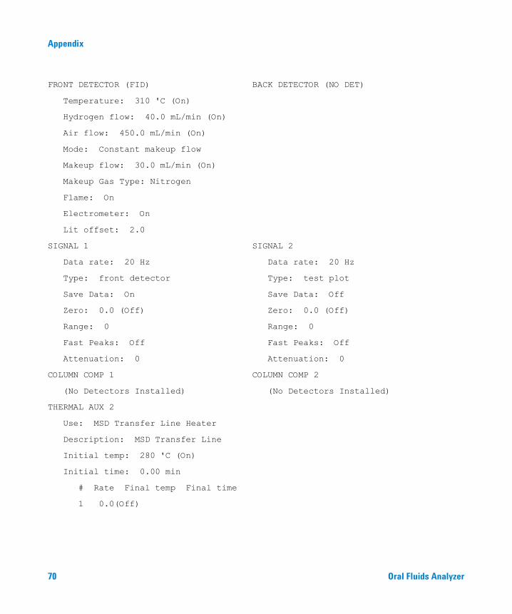
FRONT DETECTOR (FID) BACK DETECTOR (NO DET)
Temperature: 310 'C (On)
Hydrogen flow: 40.0 mL/min (On)
Air flow: 450.0 mL/min (On)
Mode: Constant makeup flow
Makeup flow: 30.0 mL/min (On)
Makeup Gas Type: Nitrogen
Flame: On
Electrometer: On
Lit offset: 2.0
SIGNAL 1 SIGNAL 2
Data rate: 20 Hz Data rate: 20 Hz
Type: front detector Type: test plot
Save Data: On Save Data: Off
Zero: 0.0 (Off) Zero: 0.0 (Off)
Range: 0 Range: 0
Fast Peaks: Off Fast Peaks: Off
Attenuation: 0 Attenuation: 0
COLUMN COMP 1 COLUMN COMP 2
(No Detectors Installed) (No Detectors Installed)
THERMAL AUX 2
Use: MSD Transfer Line Heater
Description: MSD Transfer Line
Initial temp: 280 'C (On)
Initial time: 0.00 min
# Rate Final temp Final time
1 0.0(Off)
70 Oral Fluids Analyzer
Appendix
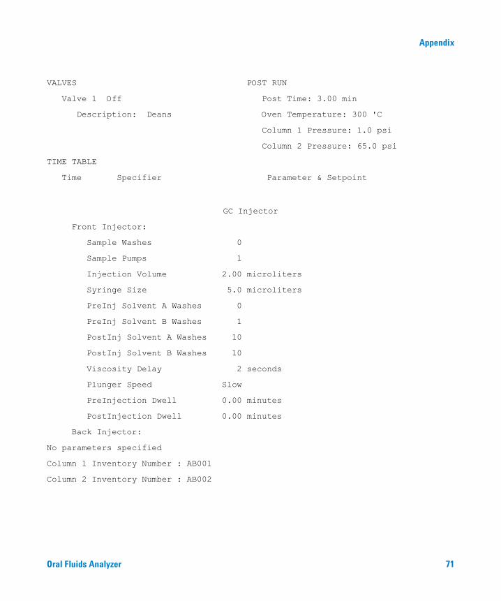
VALVES POST RUN
Valve 1 Off Post Time: 3.00 min
Description: Deans Oven Temperature: 300 'C
Column 1 Pressure: 1.0 psi
Column 2 Pressure: 65.0 psi
TIME TABLE
Time Specifier Parameter & Setpoint
GC Injector
Front Injector:
Sample Washes 0
Sample Pumps 1
Injection Volume 2.00 microliters
Syringe Size 5.0 microliters
PreInj Solvent A Washes 0
PreInj Solvent B Washes 1
PostInj Solvent A Washes 10
PostInj Solvent B Washes 10
Viscosity Delay 2 seconds
Plunger Speed Slow
PreInjection Dwell 0.00 minutes
PostInjection Dwell 0.00 minutes
Back Injector:
No parameters specified
Column 1 Inventory Number : AB001
Column 2 Inventory Number : AB002
Oral Fluids Analyzer 71

Appendix
MS ACQUISITION PARAMETERS
General Information ------- -----------
Tune File : ATUNE.U
Acquistion Mode : SIM
MS Information -- -----------
Solvent Delay : 5.00 min
EM Absolute : False
EM Offset : 200
Resulting EM Voltage : 976.5
[Sim Parameters]
GROUP 1
Group ID : THC
Resolution : Low
Plot 1 Ion : 371.20
Ions/Dwell In Group ( Mass, Dwell) ( Mass, Dwell) ( Mass, Dwell)
(303.10, 10) (303.20, 10) (371.20, 10)
(374.20, 10) (386.20, 10) (389.20, 10)
[MSZones]
MS Quad : 150 C maximum 200 C
MS Source : 280 C maximum 290 C
END OF MS ACQUISITION PARAMETERS
72 Oral Fluids Analyzer

Appendix
TUNE PARAMETERS for SN:-----------------------------
EMISSION : 34.610
ENERGY : 69.922
REPELLER : 19.904
IONFOCUS : 84.463
ENTRANCE_LE : 22.000
EMVOLTS : 776.471
AMUGAIN : 1693.000
AMUOFFSET : 119.938
FILAMENT : 1.000
DCPOLARITY : 0.000
ENTLENSOFFS : 18.071
MASSGAIN : -694.000
MASSOFFSET : -36.000
END OF TUNE PARAMETERS------------------------------------
END OF INSTRUMENT CONTROL PARAMETERS------------------------------------
Oral Fluids Analyzer
73
74
Appendix
Oral Fluids Analyzer

Index
Symbols“, 14, 15“Backflush” configuration, 16“Cut” configuration, 15“No cut” configuration, 14
AALS configuration parameters, 21Analyzer eMethod Setpoints, 67Analyzer system, 9Analyzing Your Own Samples, 51
CCheckout, Verification, and
Familiarization, 20choosing appropriate “cut” times, 26Column / Restrictor Tubing
Replacement, 59Column 1, 11Column 2, 11Column and restrictor tube routing, 60Column considerations, 59Connection, GC Cryo Trap, 19
DDean’s switch connections, 62Dean’s switch plate, 60Determine the cut time, 32Determine your cryo trap temperature
program times, 38Disable the MSD, 26
EeMethod, 20Enter cut times into the method, 34
Oral Fluids Analyzer
FFID Restrictor tube, 9, 60For more information, 16forward column, 60
GGeneral Safety, 7
HHardware configuration, 12heart cutting, 10
IInstalling the Analyzer, 18
MMaintenance, 9, 59manually started analysis, 31MSD SIM parameters, 21
OOFA_THC_Base.emeth, 20oven interior, 12Overview, 10
PPost-Run and Column Backflushing, 52Primary column, 9publication 5969-1573, 64publication 5989-5111EN, 58publication 5989-5668EN, 16, 64
Rrearward column, 60
Restrictor tube length is critical, 60Routing Column 2, 61
SSafety, 7Secondary column, 9signal views, 26Simplified Backflush, 58solenoid valve, 18status monitors, 25Swaging SilTite Ferrules, 64syringe volume, 27
TTHC test sample, 30
75

Index
76
Oral Fluids Analyzer

Agilent Technologies
© Agilent Technologies, Inc.
Printed in USA, October 2006
G1540-90000