agilent 54621a/22a/24a oscilloscope and agilent …€¦ · · 2001-06-05simplify design and...
TRANSCRIPT

service.book Page i Tuesday, February 13, 2001 2:59 PM
Service Guide
Publication Number 54622-97025February 2001
For Safety Information, Warranties, and Regulatory information, see the pages at the end of this book.
© Copyright Agilent Technologies 2000, 2001All Rights Reserved
Agilent 54621A/22A/24AOscilloscope and
Agilent 54621D/22D Mixed-Signal Oscilloscope
service.book Page ii Tuesday, February 13, 2001 2:59 PM
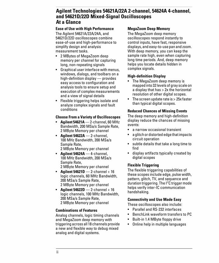
Agilent Technologies 54621A/22A 2-channel, 54624A 4-channel, and 54621D/22D Mixed-Signal Oscilloscopes At a GlanceEase of Use with High PerformanceThe Agilent 54621A/22A/24A, and 54621D/22D oscilloscopes combine ease-of-use and high-performance to simplify design and analysis measurement tasks. • 2 MBytes of MegaZoom deep
memory per channel for capturing long, non-repeating signals
• Graphical user interface with menus, windows, dialogs, and toolbars on a high-definition display — provides easy access to configuration and analysis tools to ensure setup and execution of complex measurements and a view of signal details
• Flexible triggering helps isolate and analyze complex signals and fault conditions
Choose From a Variety of Oscilloscopes• Agilent 54621A — 2-channel, 60 MHz
Bandwidth, 200 MSa/s Sample Rate, 2 MByte Memory per channel
• Agilent 54622A — 2-channel, 100 MHz Bandwidth, 200 MSa/s Sample Rate, 2 MByte Memory per channel
• Agilent 54624A — 4-channel, 100 MHz Bandwidth, 200 MSa/s Sample Rate, 2 MByte Memory per channel
• Agilent 54621D — 2-channel + 16 logic channels, 60 MHz Bandwidth, 200 MSa/s Sample Rate, 2 MByte Memory per channel
• Agilent 54622D — 2-channel + 16 logic channels, 100 MHz Bandwidth, 200 MSa/s Sample Rate, 2 MByte Memory per channel
Combinations of FeaturesAnalog channels, logic timing channels and MegaZoom deep memory with triggering across all 18 channels provide a new and flexible way to debug mixed analog and digital systems.
MegaZoom Deep MemoryThe MegaZoom deep memory oscilloscopes respond instantly to control inputs, have fast, responsive displays, and easy-to-use pan and zoom. With deep memory, you can keep the sample rate high, even when capturing long time periods. And, deep memory helps you locate details hidden in complex signals.
High-definition Display• The MegaZoom deep memory is
mapped into 32 levels of gray scale on a display that has > 2x the horizontal resolution of other digital scopes.
• The screen update rate is > 25x faster than typical digital scopes.
Reduced Chances of Missing EventsThe deep memory and high-definition display reduce the chances of missing events:• a narrow occasional transient• a glitch or distorted edge that impacts
circuit operation• subtle details that take a long time to
find• display artifacts typically created by
digital scopes
Flexible TriggeringThe flexible triggering capabilities of these scopes include edge, pulse width, pattern, glitch, TV, and sequence and duration triggering. The I2C trigger mode helps verify inter-IC communication handshaking.
Connectivity and Use Made EasyThese oscilloscopes also include:• Parallel and RS-232 interfaces• BenchLink waveform transfers to PC• Built-in 1.4 MByte floppy drive• Online help in multiple languages
ii

service.book Page iii Tuesday, February 13, 2001 2:59 PM
54621A/22A 2-channel Oscilloscope
54624A 4-channel Oscilloscope
54621D/22D Mixed-Signal Oscilloscope
Triggering
Analog Channels (2)
ProbeCompensator
MegaZoom Deep Memory Oscilloscopes
Bandwidth, Sample Rate
High-definition Display
Analog Channels (4)
Analog Channels (2)
Digital Channels (16)
iii
service.book Page iv Tuesday, February 13, 2001 2:59 PM
In This Book
This book provides the service information for the Agilent 54621A/22A/24A Oscilloscope and the Agilent 54621D/22D Mixed-Signal Oscilloscope.
This manual is divided into these chapters:
Chapter 1 provides general information and specifications.
Chapter 2 shows you how to prepare the oscilloscope for use.
Chapter 3 gives performance tests.
Chapter 4 covers calibration and adjustment procedures.
Chapter 5 provides troubleshooting information.
Chapter 6 gives the procedures and techniques for replacing assemblies and other parts.
Chapter 7 includes a list of replaceable parts, part ordering information, and shipping information.
At the back of the book you will find Safety information, Warranties, and Regulatory information.
iv
Contents
service.book Page 1 Tuesday, February 13, 2001 2:59 PM
1 General Information
To inspect package contents 1-3To inspect options and accessories 1-5Performance Characteristics 1-8
2 Preparing the Oscilloscope for Use
Setting up the Oscilloscope 2-3
To adjust the handle 2-4To power-on the oscilloscope 2-5To adjust the display intensity 2-6To connect the oscilloscope probes 2-7To use the digital probes (mixed-signal oscilloscope only) 2-8To connect a printer 2-12To connect an RS-232 cable 2-12To verify basic oscilloscope operation 2-13
Getting started using the oscilloscope interface 2-14
Using Quick Help 2-16
Selecting a language for Quick Help when the oscilloscope starts up 2-16Selecting a language for Quick Help after you have been operating the oscilloscope 2-17Loading a language from floppy disk 2-18
Cleaning the oscilloscope 2-19
3 Testing Performance
To construct the test connectors 3-3To test the 54621D/22D Oscilloscope digital channels 3-6To verify threshold accuracy 3-7To verify voltage measurement accuracy 3-11To verify bandwidth 3-14To verify horizontal ∆t and 1/∆t accuracy 3-16To verify trigger sensitivity 3-1854622A/22D/24A Performance Test Record 3-2154621A/21D Performance Test Record 3-22
4 Calibrating and Adjusting
To adjust the power supply 4-4To perform User Cal 4-7To adjust the oscilloscope display 4-8
Contents-1
Contents
service.book Page 2 Tuesday, February 13, 2001 2:59 PM
5 Troubleshooting
Solving General Problems with the Oscilloscopes 5-3If there is no trace display 5-3If the trace display is unusual or unexpected 5-4If you cannot see a channel 5-5
Troubleshooting the Oscilloscope 5-6
To construct your own dummy load 5-7To check out the oscilloscope 5-8To check the Low Voltage Power Supply 5-11To run the internal self-tests 5-13
6 Replacing Assemblies
To remove the cabinet 6-4To remove the fan 6-4To remove the floppy drive 6-4To remove the front panel 6-5To remove the display 6-6To remove the system board 6-6To remove the front-panel BNC connectors 6-6To remove the power supply 6-7To remove the keyboard 6-8To remove the handle 6-8
7 Replaceable Parts
To order a replacement part 7-3
Contents-2

service.book Page 1 Tuesday, February 13, 2001 2:59 PM
1
General Information

service.book Page 2 Tuesday, February 13, 2001 2:59 PM
General Information
This chapter lists general information for the Agilent 54620-series Oscilloscopes. It also includes performance characteristics and specifications for the oscilloscopes.
1-2

General Information
service.book Page 3 Tuesday, February 13, 2001 2:59 PM
To inspect package contents
Inspect the shipping container for damage.
If your shipping container appears to be damaged, keep the shipping container or cushioning material until you have inspected the contents of the shipment for completeness and have checked the oscilloscope mechanically and electrically.
Verify that you received the following items and any optional accessories in the oscilloscope packaging (see figure following).
• 54620-Series Oscilloscope (54621A, 21D, 22A, 22D, or 24A)
• 10074C 10:1 passive probes:(2) for 54621A, 21D, 22A, or 22D oscilloscopes(4) for 54624A oscilloscope
• 54620-68701 digital probe kit (for 54621D or 22D)
• Accessory pouch and front-panel cover (standard for 54622A, 22D, and 24A)(optional on 54621A and 21D; order N2726A)
• Power cord (see table 1-3)
• IntuiLink for 5462x-series Oscilloscopes (formerly BenchLink XL 54600) software and RS-232 cable (for 54622A, 22D, or 24A)
IntuiLink software is available free on the web at: www.agilent.com/find/5462xswRS-232 cable may be ordered separately, part number 34398A
If anything is missing, contact your nearest Agilent Sales Office. If the shipment was damaged, contact the carrier, then contact the nearest Agilent Sales Office.
Inspect the oscilloscope
• If there is mechanical damage or a defect, or if the oscilloscope does not operate properly or does not pass the performance tests listed in the Service Guide, notify your Agilent Sales Office.
• If the shipping container is damaged, or the cushioning materials show signs of stress, notify the carrier and your Agilent Sales Office. Keep the shipping materials for the carrier’s inspection. The Agilent Sales Office will arrange for repair or replacement at Agilent’s option, without waiting for claim settlement.
1-3

General Information
service.book Page 4 Tuesday, February 13, 2001 2:59 PM
Figure 1-1
Package contents for 54620-Series Oscilloscopes
s
sa
10074C ProbesPower cord
Accessories pouch and front-panel cover**
54620-61801 16-channel cable
5959-9334 2” Ground lead (qty 5)
5090-4356 Clip (qty 20)
IntuiLink software and serial cable**
54620-Series Oscilloscope 54620-68701 digital probe kit*
* 54621D /22D only** 54622A/22D/24A only
1-4

General Information
service.book Page 5 Tuesday, February 13, 2001 2:59 PM
To inspect options and accessories
Verify that you received the options and accessories you ordered and that none were damaged.
If anything is missing, contact your nearest Agilent Sales Office. If the shipment was damaged, or the cushioning materials show signs of stress, notify the carrier and your Agilent Sales Office.
Some of the options and accessories available for the 54620-Series Oscilloscopes are listed in tables 1-1 am 1-2. Contact your Agilent Sales Office for a complete list of options and accessories.
Table 1-1 Options available
Option Description
003 Shielding Option for use in severe environments or with sensitive devices under test–shields both ways (in and out):
RS-03 magnetic interface shielding added to CRT, and RE-02 display shield added to CRT to reduce radiated interference.
0B0 Delete manuals
A6J ANSII Z540 compliant calibration with test data
W32 3-year, customer-return calibration service
W34 3-year, customer-return standard comp calibration service
W50 Additional 2-year warranty (5 years total)
W52 5-year, customer-return calibration service
W54 5-year customer-return standard comp calibration service
See table 1-3 for power cord options
1-5

General Information
service.book Page 6 Tuesday, February 13, 2001 2:59 PM
Table 1-2 Accessories available
Model Description
1146A Current probe, ac/dc
1183A Testmobile scope cart
1185A Carrying Case
1186A Rackmount Kit
10070C 1:1 Passive Probe with ID
10072A Fine-pitch probe kit
10073B 10:1 500 MHz probe with ID
10075A 0.5 mm IC clip kit
10076A 100:1, 4 kV 250 MHz probe with ID
10085A 16:16 logic cable and terminator (for use with 54621D/22D)
10089A 16:2 x 8 logic input probe assembly (shipped standard with 54621D/22D)
10100C 50Ω Termination
10833A GPIB cable, 1 m long
34398A RS-232 cable (standard with 100 MHz models)
E2613B 0.5 mm Wedge probe adapter, 3-signal, qty 2
E2614A 0.5 mm Wedge probe adapter, 8-signal, qty 1
E2615B 0.65 mm Wedge probe adapter, 3-signal, qty 2
E2616A 0.65 mm Wedge probe adapter, 8-signal, qty 1
E2643A 0.5 mm Wedge probe adapter, 16-signal, qty 1
E2644A 0.65 mm Wedge probe adapter, 16-signal, qty 1
N2726A Accessory pouch and front-panel cover (standard with 100 MHz models)
N2727A Thermal printer and pouch
N2728A 10 rolls of thermal printer paper
N2757A GPIB Interface Module
N2772A 20 MHz differential probe
N2773A Differential probe power supply
1-6

General Information
service.book Page 7 Tuesday, February 13, 2001 2:59 PM
Table 1-3
Power Cords
Plug Type Cable Part No. Plug Description Length in/cm Color Opt 903 (U.S.A.)124V **
8120-1378 Straight (NEMA5-15P*) 90/228 Jade Gray
Opt 900 (U.K.)250V
8120-1351 Straight (BS136A*) 90/228 Gray
Opt 901 (Australia)250V
8120-1369 Straight (NZSS198/ASC*) 79/200 Gray
Opt 902 (Europe)250V
8120-16898120-2857
Straight (CEE7-Y11*)Straight (Shielded)
79/20079/200 Mint GrayCoco Brown
Opt 906 (Switzerland)250V
8120-2104 Straight (SEV1011*) 79/200 Mint Gray
Opt 912 (Denmark)220V
8120-2957 Straight (DHCK107*) 79/200 Mint Gray
Opt 917 (Africa)250V
8120-4600 Straight (SABS164) 79/200 Jade Gray
Opt 918 (Japan)100V
8120-4753 Straight Miti 90/230 Dark Gray
* Part number shown for plug is industry identifier for plug only.Cable part number shown is Agilent part number for complete cable including plug.
** These cords are included in the CSA certification approval for the equipment.
1-7
General InformationAcquisition: Analog Channels
service.book Page 8 Tuesday, February 13, 2001 2:59 PM
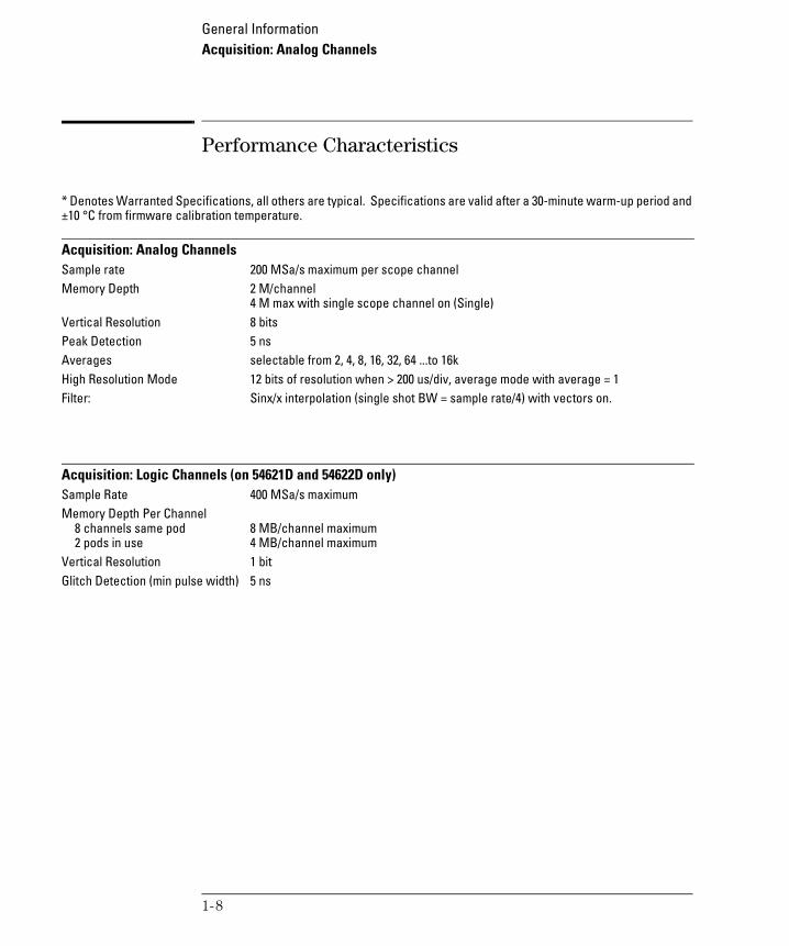
Performance Characteristics
* Denotes Warranted Specifications, all others are typical. Specifications are valid after a 30-minute warm-up period and ±10 °C from firmware calibration temperature.
Acquisition: Analog ChannelsSample rate 200 MSa/s maximum per scope channelMemory Depth 2 M/channel
4 M max with single scope channel on (Single)Vertical Resolution 8 bits Peak Detection 5 ns Averages selectable from 2, 4, 8, 16, 32, 64 ...to 16kHigh Resolution Mode 12 bits of resolution when > 200 us/div, average mode with average = 1Filter: Sinx/x interpolation (single shot BW = sample rate/4) with vectors on.
Acquisition: Logic Channels (on 54621D and 54622D only)Sample Rate 400 MSa/s maximumMemory Depth Per Channel
8 channels same pod2 pods in use
8 MB/channel maximum4 MB/channel maximum
Vertical Resolution 1 bitGlitch Detection (min pulse width) 5 ns
1-8

General InformationVertical System: Analog Channels
service.book Page 9 Tuesday, February 13, 2001 2:59 PM
Vertical System: Analog Channels54621A/D, 54622A/D Ch1 and 2 simultaneous acquisition54624A Ch 1, 2, 3 and 4 simultaneous acquisition54621A/D
Bandwidth (-3dB)*ac coupledCalculated rise time
dc to 60 MHz3.5 Hz to 60 MHz~5.8 ns (= 0.35/bandwidth)
54622A/D, 54624ABandwidth (-3dB)*ac coupledCalculated rise time
dc to 100 MHz3.5 Hz to 100 MHz~3.5 ns (= 0.35/bandwidth)
Single Shot Bandwidth 50 MHzRange1 1 mV/div to 5 V/div Maximum Input CAT I 300 Vrms, 400 Vpk
CAT II 100 Vrms, 400 Vpk with 10074C 10:1 probe: CAT I 500 Vpk, CAT II 400 Vpk
Offset Range ±5 V on ranges <10 mV/div±25 V on ranges 10 mV/div to 199 mV/div±100 V on ranges ≥200 mV/div
Dynamic Range Lesser of ±8 div or ±32 VInput Resistance 1 MΩ ±1%Input Capacitance ~ 14 pFCoupling ac, dc, groundBW Limit ~ 20 MHz selectableChannel-to-Channel Isolation dc to 20 MHz > 40 dB (with channels at same V/div)
20 MHz to max bandwidth > 30 dB Probes 10:1 10074C shipped standard for each scope channelProbe ID (Agilent/HP &
Tek Compatible) Auto probe sense
1 1 mV/div is a magnification of 2 mV/div setting. For vertical accuracy calculations, use full scale of 16 mV for 1 mV/div sensitivity setting.
* Denotes Warranted Specifications, all others are typical. Specifications are valid after a 30-minute warm-up period and ±10 °C from firmware calibration temperature.
1-9
General InformationVertical System: Analog Channels (continued)
service.book Page 10 Tuesday, February 13, 2001 2:59 PM
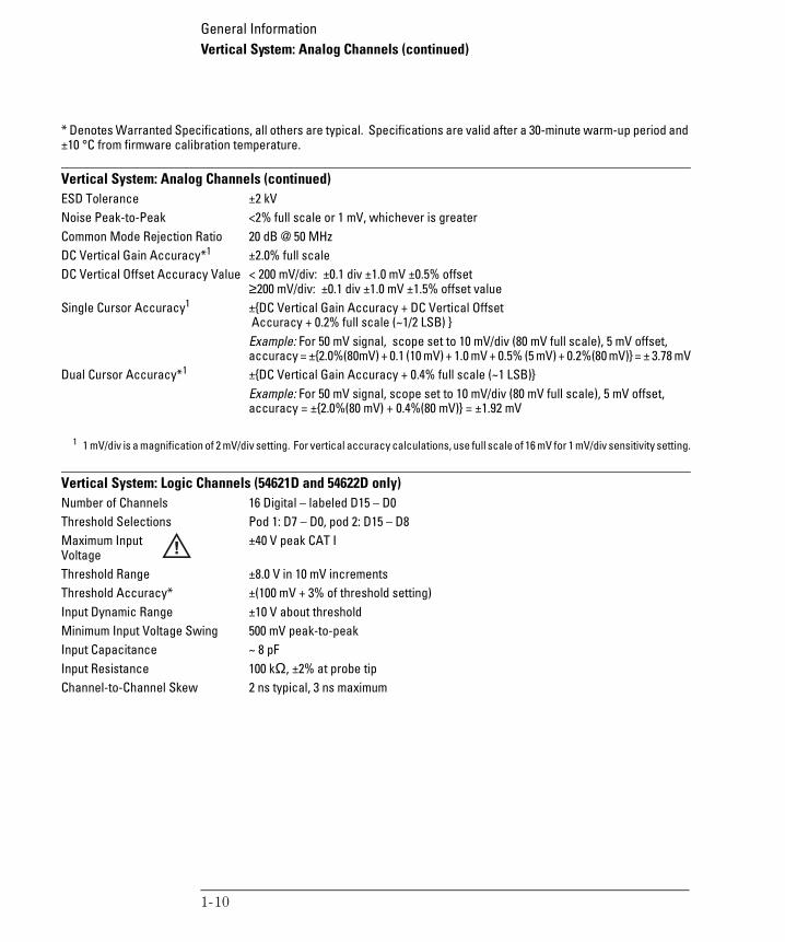
Vertical System: Analog Channels (continued)ESD Tolerance ±2 kVNoise Peak-to-Peak <2% full scale or 1 mV, whichever is greaterCommon Mode Rejection Ratio 20 dB @ 50 MHzDC Vertical Gain Accuracy*1 ±2.0% full scaleDC Vertical Offset Accuracy Value < 200 mV/div: ±0.1 div ±1.0 mV ±0.5% offset
≥200 mV/div: ±0.1 div ±1.0 mV ±1.5% offset valueSingle Cursor Accuracy1 ±DC Vertical Gain Accuracy + DC Vertical Offset
Accuracy + 0.2% full scale (~1/2 LSB) Example: For 50 mV signal, scope set to 10 mV/div (80 mV full scale), 5 mV offset, accuracy = ±2.0%(80mV) + 0.1 (10 mV) + 1.0 mV + 0.5% (5 mV) + 0.2%(80 mV) = ± 3.78 mV
Dual Cursor Accuracy*1 ±DC Vertical Gain Accuracy + 0.4% full scale (~1 LSB)Example: For 50 mV signal, scope set to 10 mV/div (80 mV full scale), 5 mV offset, accuracy = ±2.0%(80 mV) + 0.4%(80 mV) = ±1.92 mV
1 1 mV/div is a magnification of 2 mV/div setting. For vertical accuracy calculations, use full scale of 16 mV for 1 mV/div sensitivity setting.
Vertical System: Logic Channels (54621D and 54622D only)Number of Channels 16 Digital – labeled D15 – D0Threshold Selections Pod 1: D7 – D0, pod 2: D15 – D8Maximum Input Voltage
±40 V peak CAT I
Threshold Range ±8.0 V in 10 mV incrementsThreshold Accuracy* ±(100 mV + 3% of threshold setting)Input Dynamic Range ±10 V about thresholdMinimum Input Voltage Swing 500 mV peak-to-peakInput Capacitance ~ 8 pFInput Resistance 100 kΩ, ±2% at probe tipChannel-to-Channel Skew 2 ns typical, 3 ns maximum
* Denotes Warranted Specifications, all others are typical. Specifications are valid after a 30-minute warm-up period and ±10 °C from firmware calibration temperature.
1-10

General InformationHorizontal
service.book Page 11 Tuesday, February 13, 2001 2:59 PM
HorizontalRange 5 ns/div to 50 s/divResolution 40 psVernier 1-2-5 increments when off, 25 minor increments between major settings when onReference Positions Left, Center, RightDelay Range
Pre-trigger (negative delay)Post-trigger (positive delay)
Greater of 1 screen width or 10 ms500 seconds
Scope Delta-t AccuracySame Channel*
Channel-to-Channel
±0.01% reading ±0.1% screen width ±40 psExample: for signal with pulse width of 10 us, scope set to 5 us/div (50 us screen width), delta-t accuracy = ±.01%(10 us) + 0.1% (50 us) + 40 ps = 51.04 ns
±0.01% reading ±0.1% screen width ±80 psLogic Delta-t Accuracy
Same Channel
Channel-to-Channel
(non-Vernier settings)±0.01% reading ±0.1% screen width ±(1 logic sample period, 2.5 or 5 ns based on sample rate of 200/400 MSa/s)Example: for signal with pulse width of 10 us, scope set to 5 us/div (50 us screen width), and single pod active (400 MSa/s), delta-t accuracy = ±.01%(10 us) + 0.1% (50 us) + 2.5 ns = 53.5 ns±0.01% reading ±0.2% screen width ±(1 logic sample period, 2.5 or 5 ns) ±chan-to-chan skew (2 ns typical, 3 ns maximum)
Delay Jitter 10 ppmRMS Jitter 0.025% screen width + 100 ps Modes Main, Delayed, Roll, XYXY
BandwidthPhase error @ 1 MHz
Max bandwidth1.8 degrees
* Denotes Warranted Specifications, all others are typical. Specifications are valid after a 30-minute warm-up period and ±10 °C from firmware calibration temperature.
1-11

General InformationTrigger System
service.book Page 12 Tuesday, February 13, 2001 2:59 PM
Trigger SystemSources:
54621A/622A54621D/622D54624A
Ch 1, 2, line, extCh 1, 2, line, ext, D15 - D0Ch 1, 2, 3, 4, line, ext
Modes Auto, Auto level, Triggered (normal), SingleHoldoff Time ~60 ns to 10 secondsSelections Edge, Pattern, Pulse Width, TV, Sequence, I2C, Duration
Edge Trigger on a rising or falling edge of any source.Pattern Trigger on a pattern of high, low, and don’t care levels and a rising or falling edge
established across any of the sources. The analog channel’s high or low level is defined by that channel’s trigger level.
Pulse Width Trigger when a positive- or negative-going pulse is less than, greater than, or within a specified range on any of the source channels.
Minimum pulse width setting: 5 nsMaximum pulse width setting: 10 s
TV Trigger on any scope channel for NTSC, PAL, PAL-M, or SECAM broadcast standards on either positive or negative composite video signals. Modes supported include Field 1, Field 2, or both, all lines, or any line within a field. Also supports triggering on non-interlaced fields. TV trigger sensitivity: 0.5 division of synch signal.
Sequence Find event A, trigger on event B, with option to reset on event C or time delay.I2C Trigger on I2C (Inter-IC bus) serial protocol at a start/stop condition or user defined
frame with address and/or data values.Duration Trigger on a multi-channel pattern whose time duration is less than a value, greater
than a value, greater than a time value with a timeout value, or inside or outside of a set of time values.
Minimum duration setting: 5 nsMaximum duration setting: 10 s
Autoscale Finds and displays all active scope and logic channels (for 54621D/54622D), sets edge trigger mode on highest numbered channel, sets vertical sensitivity on scopes channels and thresholds on logic channels, time base to display ~1.8 periods. Requires minimum voltage >10 mVpp, 0.5% duty cycle and minimum frequency >50 Hz.
* Denotes Warranted Specifications, all others are typical. Specifications are valid after a 30-minute warm-up period and ±10 °C from firmware calibration temperature.
1-12

General InformationAnalog Channel Triggering
service.book Page 13 Tuesday, February 13, 2001 2:59 PM
Analog Channel Triggering Range (Internal) ±6 divSensitivity* Greater of 0.35 div or 2.5 mVCoupling ac (~3.5 Hz), dc, noise reject, HF reject and LF reject (~ 50 kHz)
Logic (D15 - D0) Channel Triggering (54621D and 54622D)Threshold Range (used defined) ±8.0 V in 10 mV incrementsThreshold Accuracy* ±(100 mV + 3% of threshold setting)Predefined Thresholds TTL = 1.4 V, CMOS = 2.5 V, ECL = -1.3 V
External (EXT) TriggeringInput Resistance 1 MΩ, ±3%Input Impedance ~ 14 pFMaximum Input CAT I 300 Vrms, 400 Vpk
CAT II 100 Vrms, 400 Vpkwith 10074C 10:1 probe:CAT I 500 Vpk, CAT II 400 Vpk
Range ±10 VSensitivity dc to 25 MHz, < 75 mV
25 MHz to max bandwidth, < 150 mVCoupling ac (~ 3.5 Hz), dc, noise reject, HF reject and LF reject (~ 50 kHz)
* Denotes Warranted Specifications, all others are typical. Specifications are valid after a 30-minute warm-up period and ±10 °C from firmware calibration temperature.
1-13

General InformationDisplay System
service.book Page 14 Tuesday, February 13, 2001 2:59 PM
Display SystemDisplay 7-inch raster monochrome CRTThroughput of Scope Channels 25 million gray scale vectors/sec per channelResolution
High-performance custom graphics display processor
255 vertical by 1000 horizontal points (waveform area)32 levels of gray scale
400 MB/sec graphics BW / channel2 MB SGRAM (Agilent 54621A/D and 54622A/D)4 MB SGRAM (Agilent 54624A)
Controls Waveform intensity on front panelVectors on/off; infinite persistence on/off8 x 10 grid with continuous intensity control
Built-in Help System Key-specific help in 9 languages displayed by pressing and holding key or softkey of interest
Real Time Clock Time and date (user setable)
Measurement FeaturesAutomatic Measurements Measurements are continuously updated
Cursors track current measurementVoltage (scope channels only) Peak-to-Peak, Maximum, Minimum, Average, Amplitude, Top, Base, Overshoot,
Undershoot, RMS (front panel: dc; GPIB: ac and dc) Time Frequency, Period, + Width, – Width, Duty Cycle, X at Max (Time at max volts) on any
channels. Rise time and Fall time on scope channels onlyThreshold Definition 10%, 50%, 90% for time measurementsCursors Manually or automatically placed readout of Horizontal (X, ∆X, 1/∆X) and
Vertical (Y, ∆Y). Additionally logic or scope channels can be displayed as binary or hex values
Waveform Math One function of 1-2, 1*2, FFT, dV/dt, ∫Vdt. Source of FFT, dV/dt, ∫Vdt: scope channels 1 or 2, 1-2, 1+2, 1*2
* Denotes Warranted Specifications, all others are typical. Specifications are valid after a 30-minute warm-up period and ±10 °C from firmware calibration temperature.
1-14

General InformationFFT
service.book Page 15 Tuesday, February 13, 2001 2:59 PM
FFTPoints Fixed at 2048 pointsSource of FFT Scope channels 1 or 2, 1+2, 1-2, 1*2Window Rectangular, Flattop, HanningNoise Floor -70 to -100 dB depending on averagingAmplitude Display In dBVFrequency Resolution: 0.097656/(time per div)Maximum Frequency 102.4/(time per div)
StorageSave/Recall (non-volatile) 3 setups and traces can be saved and recalled internallyFloppy Disk
Image formatsData formatsTrace/setup formats
3.5” 1.44 Mbytes double densityTIF, BMPX and Y (time/voltage) values in CSV formatRecalled
I/ORS-232 (serial) standard port 1 port; XON or DTR; 8 data bits; 1 stop bits; No parity; 9600, 19200, 38400, 57600 baud ratesParallel standard port Printer supportPrinter Compatibility DeskJet, LaserJet with HP PCL 3 or greater
Compatibility– black and white @150x150 dpigray scale @ 600x600 dpi
Epson–black and white @180x180 dpiSeiko–DPU-414 black and white
Optional GPIB Interface Module Fully programmable with IEEE488.2 compliance
* Denotes Warranted Specifications, all others are typical. Specifications are valid after a 30-minute warm-up period and ±10 °C from firmware calibration temperature.
1-15

General InformationGeneral Characteristics
service.book Page 16 Tuesday, February 13, 2001 2:59 PM
General CharacteristicsPhysical:
SizeWeight
32.26 cm wide x 17.27 cm high x 31.75 cm deep (without handle)~ 6.35 kgs (14 lbs)
Calibrator Output Frequency ~1.2 kHz; Amplitude 5 VTrigger Out 0 to 5 V with 50 Ω source impedance; delay ~ 55 nsPrinter Power 7.2 to 9.2 V, 1 A
Power RequirementsLine Voltage Range 100 - 240 VAC ±10%, CAT II, automatic selectionLine Frequency 47 to 440 HzPower Usage 100 W max
Environmental Characteristics Ambient Temperature Operating -10 °C to +55 °C
Non-operating -51 °C to +71 °CHumidity Operating 95% RH at 40 °C for 24 hr
Non-operating 90% RH at 65 °C for 24 hrAltitude Operating to 4,570 m (15,000 ft)
Non-operating to 15,244 m (50,000 ft)Vibration HP/Agilent class B1 and MIL-PRF-28800F Class 3 randomShock HP/Agilent class B1 and MIL-PRF-28800F (operating 30 g, 1/2 sine, 11-ms duration, 3
shocks/axis along major axis. Total of 18 shocks)Pollution degree2 Normally only dry non-conductive pollution occurs. Occasionally a temporary
conductivity caused by condensation must be expected.Indoor use only This instrument is rated for indoor use only
Installation categories CAT I: Mains isolatedCAT II: Line voltage in appliance and to wall outlet
* Denotes Warranted Specifications, all others are typical. Specifications are valid after a 30-minute warm-up period and ±10 °C from firmware calibration temperature.
1-16

service.book Page 1 Tuesday, February 13, 2001 2:59 PM
2
Preparing the Oscilloscope for Use

service.book Page 2 Tuesday, February 13, 2001 2:59 PM
Preparing the Oscilloscope for Use
To prepare your oscilloscope for use, you need to do the following tasks. After you have completed them, you will be ready to use the oscilloscope.
In the following topics you will:
• adjust the handle
• power-on the oscilloscope
• adjust the display intensity• connect the oscilloscope probes
• connect the digital probes (with 54621D and 54622D)
• connect a printer• connect a RS-232 cable
• verify basic oscilloscope operation
• get started using the oscilloscope interface• learn how to use Quick Help
This chapter also tells you how to:
• clean the oscilloscope
2-2

service.book Page 3 Tuesday, February 13, 2001 2:59 PM
Setting up the Oscilloscope
After you have done a few basic tasks, you will connect probes to the oscilloscope. The number of probes, and the type of probes that you will use depends on the oscilloscope model that you have.
• When using the Agilent 54621A and 54622A 2-channel Oscilloscopes, and the Agilent 54624A 4-channel Oscilloscope, you will connect and use analog probes to examine analog signals.
• When using the Agilent 54621D and 54622D Mixed-Signal Oscilloscopes, you will connect and use both analog and digital probes to examine analog and digital signals.
Analog channels(2 or 4, depending
on the oscilloscopemodel)
Analog channels (2)
Digital channels (16)
2-3

Preparing the Oscilloscope for UseTo adjust the handle
service.book Page 4 Tuesday, February 13, 2001 2:59 PM
To adjust the handle
1 Grasp the handle pivot points on each side of the instrument and pull the pivot out until it stops.
2 Without releasing the pivots, swivel the handle to the desired position. Then release the pivots. Continue pivoting the handle until it clicks into a set position.
54622DMIXED SIGNAL OSCILLOSCOPE
CHANNEL
INPUTS
5 ns1 s150
Time/DivSelect
sAgilent
2-4

Preparing the Oscilloscope for UseTo power-on the oscilloscope
service.book Page 5 Tuesday, February 13, 2001 2:59 PM
To power-on the oscilloscope
1 Connect the power cord to the rear of the oscilloscope, then to a suitable ac voltage source.
The oscilloscope power supply automatically adjusts for input line voltages in the range 100 to 240 VAC. Therefore, you do not need to adjust the input line voltage setting. The line cord provided is matched to the country of origin. Ensure that you have the correct line cord. See table 1-3
2 Press the power switch.
Some front panel key lights will come on and the oscilloscope will be operational in about 5 seconds.
~5V
Trigger out
2-5
Preparing the Oscilloscope for UseTo adjust the display intensity
service.book Page 6 Tuesday, February 13, 2001 2:59 PM
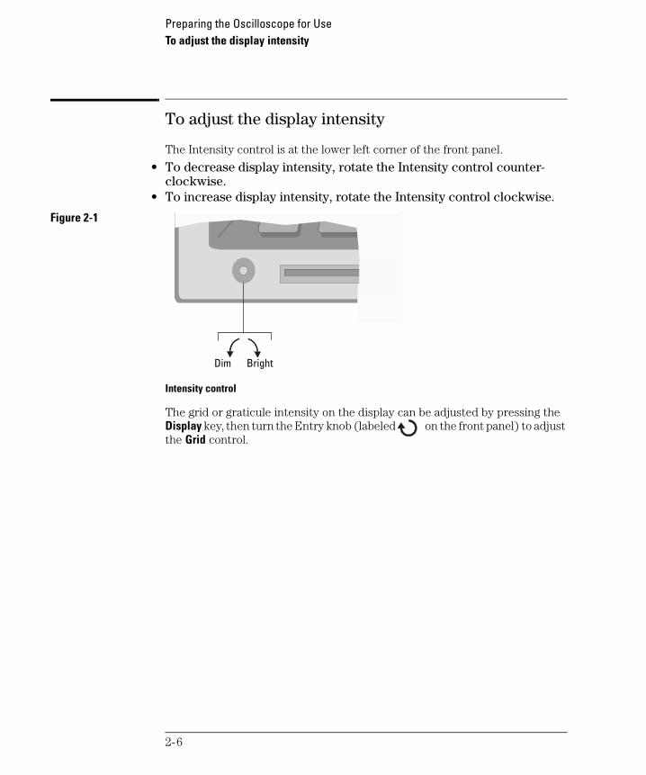
To adjust the display intensity
The Intensity control is at the lower left corner of the front panel.
• To decrease display intensity, rotate the Intensity control counter-clockwise.
• To increase display intensity, rotate the Intensity control clockwise.
Figure 2-1
Intensity control
The grid or graticule intensity on the display can be adjusted by pressing the Display key, then turn the Entry knob (labeled on the front panel) to adjust the Grid control.
BrightDim
2-6

Preparing the Oscilloscope for UseTo connect the oscilloscope probes
service.book Page 7 Tuesday, February 13, 2001 2:59 PM
To connect the oscilloscope probes
1 Connect the Agilent 10074C 1.5-meter, 10:1 oscilloscope probe to the analog channel 1 or 2 BNC connector input on the oscilloscope, or channel 1 through channel 4 on the 54624A.Maximum input voltage for analog inputs:
CAT I 300 Vrms, 400 VpkCAT II 100 Vrms, 400 Vpkwith 10074C 10:1 probe: CAT I 500 Vpk, CAT II 400 Vpk
2 Connect the retractable hook tip on the probe tip to the circuit point of interest. Be sure to connect the probe ground lead to a ground point on the circuit.The probe ground lead is connected to the oscilloscope chassis and the ground wire in the power cord. If you need to connect the ground lead to a point in the circuit that cannot be grounded to power ground, consider using a differential probe.
2-7
Preparing the Oscilloscope for UseTo use the digital probes (mixed-signal oscilloscope only)
service.book Page 8 Tuesday, February 13, 2001 2:59 PM
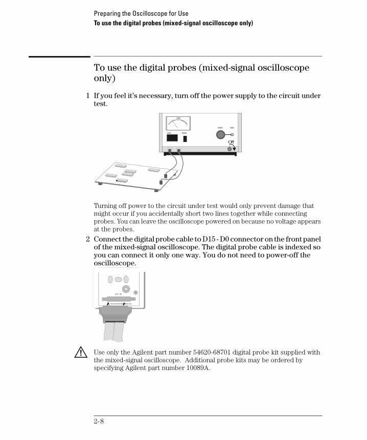
To use the digital probes (mixed-signal oscilloscope only)
1 If you feel it’s necessary, turn off the power supply to the circuit under test.
Turning off power to the circuit under test would only prevent damage that might occur if you accidentally short two lines together while connecting probes. You can leave the oscilloscope powered on because no voltage appears at the probes.
2 Connect the digital probe cable to D15 - D0 connector on the front panel of the mixed-signal oscilloscope. The digital probe cable is indexed so you can connect it only one way. You do not need to power-off the oscilloscope.
Use only the Agilent part number 54620-68701 digital probe kit supplied with the mixed-signal oscilloscope. Additional probe kits may be ordered by specifying Agilent part number 10089A.
Off
2-8

Preparing the Oscilloscope for UseTo use the digital probes (mixed-signal oscilloscope only)
service.book Page 9 Tuesday, February 13, 2001 2:59 PM
3 Connect a clip to one of the probe leads. Be sure to connect the ground lead. (Other probe leads are omitted from the figure for clarity.)
4 Connect the clip to a node in the circuit you want to test.
Clip
2-9

Preparing the Oscilloscope for UseTo use the digital probes (mixed-signal oscilloscope only)
service.book Page 10 Tuesday, February 13, 2001 2:59 PM
5 For high-speed signals, connect a ground lead to the probe lead, connect a clip to the ground lead, and attach the clip to ground in the circuit under test.
6 Connect the ground lead on each set of channels, using a probe clip. The ground lead improves signal fidelity to the instrument, ensuring accurate measurements.
Signal Lead
Ground Lead
Clip
Circuit Ground
Channel Pod Ground
2-10
Preparing the Oscilloscope for UseTo use the digital probes (mixed-signal oscilloscope only)
service.book Page 11 Tuesday, February 13, 2001 2:59 PM
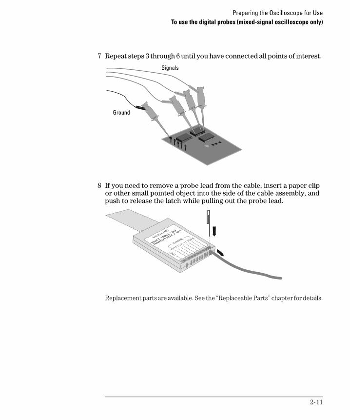
7 Repeat steps 3 through 6 until you have connected all points of interest.
8 If you need to remove a probe lead from the cable, insert a paper clip or other small pointed object into the side of the cable assembly, and push to release the latch while pulling out the probe lead.
Replacement parts are available. See the “Replaceable Parts” chapter for details.
Signals
Ground
2-11

Preparing the Oscilloscope for UseTo connect a printer
service.book Page 12 Tuesday, February 13, 2001 2:59 PM
To connect a printer
The oscilloscope connects to a parallel printer through the Parallel output connector on the rear of the oscilloscope. You will need a parallel printer cable to connect to the printer.
1 Attach the 25-pin small “D” connector to the Parallel output connector on the rear of the oscilloscope. Tighten the thumbscrews on the cable connector to secure the cable.
2 Attach the larger 36-pin “D” connector to the printer.3 Set up the printer configuration on the oscilloscope.
a Press the Utility key, then press the Print Confg softkey.b Press the Print to: softkey and set the interface to Parallel.c Press the Format softkey and select your printer format from the list.For more information on printer configuration, refer to the “Utilities” chapter in the User’s Guide.
To connect an RS-232 cable
The oscilloscope can be connected to a controller or a PC through the RS-232 connector on the rear of the oscilloscope. An RS-232 cable is shipped with each 54622A/22D/24A oscilloscope and may be purchased for the 54621A/21D oscilloscopes.
1 Attach the 9-pin “D” connector on the RS-232 cable to the RS-232 connector on the rear of the oscilloscope. Tighten the thumbscrews on the cable connector to secure the cable
2 Attach the other end of the cable to your controller or pc.3 Set up the RS-232 configuration on the oscilloscope.
a Press the Utility key, then press the I/O softkey.b Press the Controller softkey and select RS-232.c Press the Baud softkey and set the baud rate to match your controller or pc.d Press the XON DTR softkey and set the handshake to match your controller
or pc.For more information on RS-232 configuration, refer to the “Utilities” chapter in the User’s Guide.
2-12

Preparing the Oscilloscope for UseTo verify basic oscilloscope operation
service.book Page 13 Tuesday, February 13, 2001 2:59 PM
To verify basic oscilloscope operation
1 Connect an oscilloscope probe to channel 1.2 Attach the probe to the Probe Comp output on the lower-right side of
the front panel of the oscilloscope.Use a probe retractable hook tip so you do not need to hold the probe.
3 Press the Save/Recall key on the front panel, then press the Default Setup softkey under the display.The oscilloscope is now configured to its default settings.
4 Press the Autoscale key on the front panel.You should then see a square wave with peak-to-peak amplitude of about 5 divisions and a period of about 4 divisions as shown below. If you do not see the waveform, ensure your power source is adequate, the oscilloscope is properly powered-on, and the probe is connected securely to the front-panel channel input BNC and to the Probe Comp calibration output.
Verifying Basic Oscilloscope Operation
2-13
service.book Page 14 Tuesday, February 13, 2001 2:59 PM
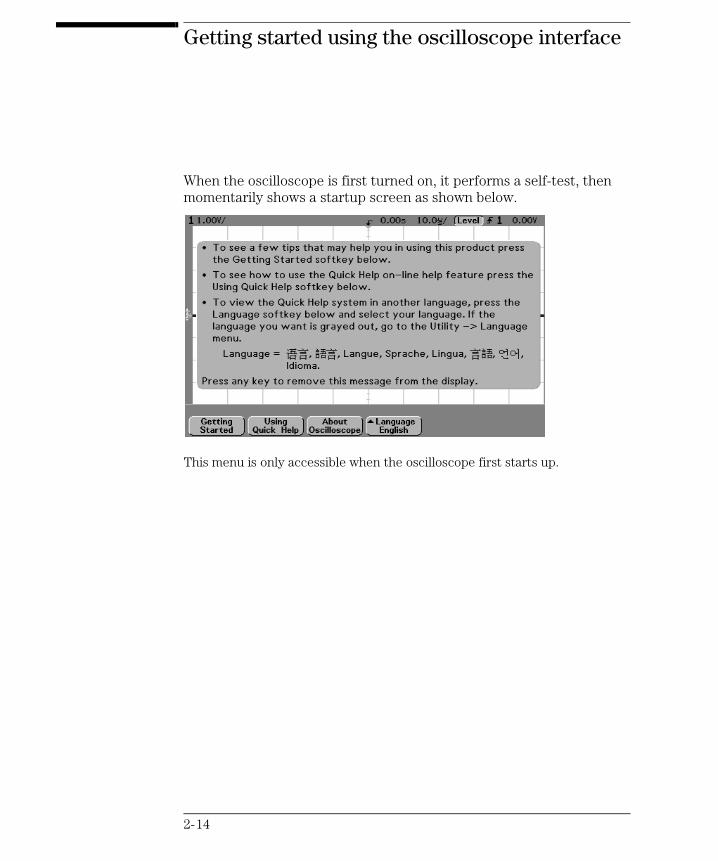
Getting started using the oscilloscope interface
When the oscilloscope is first turned on, it performs a self-test, then momentarily shows a startup screen as shown below.
This menu is only accessible when the oscilloscope first starts up.
2-14

Preparing the Oscilloscope for UseTo verify basic oscilloscope operation
service.book Page 15 Tuesday, February 13, 2001 2:59 PM
• Press the Getting Started softkey to view the symbols used in the oscilloscope softkey menus.
Use the Entry knob labeled to adjust the parameter.
Press the softkey to display a pop up with a list of choices. Repeatedly press the softkey until your choice is selected.
Use the Entry knob labeled or press the softkey to adjust the parameter.
Option is selected and operational.
Feature is on. Press the softkey again to turn the feature off.
Feature is off. Press the softkey again to turn the feature on.
Press the softkey to view the menu.
Press the softkey to return to the previous menu.
Press the softkey to view additional selections.
Links you to another menu.
2-15

service.book Page 16 Tuesday, February 13, 2001 2:59 PM
Using Quick Help
The oscilloscope has a Quick Help system that provides user help for each front-panel key and softkey on the oscilloscope. To view Quick Help information:
1 Press and hold down the key for which you would like to view help.2 Release the key after reading the message. Releasing the key returns
the oscilloscope to the previous state.
Selecting a language for Quick Help when the oscilloscope starts up
When the oscilloscope first powers up, you can press the Language softkey to select a language for viewing Quick Help. Successive press the Language softkey until the desired language in the list selected.
You can also select and load a language later from the Utility Language menu.
2-16

Preparing the Oscilloscope for UseSelecting a language for Quick Help after you have been operating the oscilloscope
service.book Page 17 Tuesday, February 13, 2001 2:59 PM
Selecting a language for Quick Help after you have been operating the oscilloscope
1 Press the Utility key, then press the Language softkey to display the Language menu.
2 Press the Language softkey until the desired language in the list selected.
If the language you want to load is grayed-out in the list, you will need to load the language from floppy disk. The language file can be downloaded from www.agilent.com/find/5462xsw or call an Agilent center and request a language disk for your instrument
2-17

Preparing the Oscilloscope for UseLoading a language from floppy disk
service.book Page 18 Tuesday, February 13, 2001 2:59 PM
Loading a language from floppy disk
Language files can be downloaded from www.agilent.com/find/5462xsw or call an Agilent center and request a language disk for your instrument.
1 Insert the floppy disk with a language file into the floppy disk drive on the oscilloscope.
2 Press the Utility key, then press the Language softkey to display the Language menu.
3 Press the Load/Del softkey to select the language to be loaded.4 Press the Load Language softkey to load the selected language into the
oscilloscope.
For more information about loading and deleting languages, refer to the “Utilities” chapter in the User’s Guide.
2-18
service.book Page 19 Tuesday, February 13, 2001 2:59 PM
Cleaning the oscilloscope
1 Disconnect power from the instrument.
C A U T I O N Avoid Damage to Sensitive Electronic Components!
Do not use too much liquid in cleaning the oscilloscope. Water can enter the front-panel keyboard, control knobs, or floppy disk damaging sensitive electronic components.
2 Clean the oscilloscope with a soft cloth dampened with a mild soap and water solution.
3 Make sure that the instrument is completely dry before reconnecting to a power source.
2-19

service.book Page 20 Tuesday, February 13, 2001 2:59 PM
2-20

service.book Page 1 Tuesday, February 13, 2001 2:59 PM
3
Testing Performance
service.book Page 2 Tuesday, February 13, 2001 2:59 PM
Testing Performance
This chapter explains how to verify correct oscilloscope operation and perform tests to ensure that the oscilloscope meets the performance specifications.
To completely test and troubleshoot the oscilloscope, you will create and use two test connector accessories, as described in this chapter.
• The test connectors make it easy for you to connect the oscilloscope probes to function generators and measurement equipment with minimum electrical distortion.
• The connectors are used in the threshold and time interval tests.
3-2

Testing PerformanceTo construct the test connectors
service.book Page 3 Tuesday, February 13, 2001 2:59 PM
To construct the test connectors
The Agilent 54621D/22D Mixed-Signal Oscilloscope has digital channels that you will need to connect to test equipment during testing. To easily connect the digital channels, you will construct two test connectors.
Table 3-1 Materials Required to Construct the Test Connectors
Construct Test Connectors Only for the 54621D/22D Mixed-Signal Oscilloscope
You need to construct the test connectors only if you will be connecting the Agilent 54621D/22D Oscilloscope models to the test equipment.
Description Recommended Part Qty
BNC (f) Connector Agilent 1250-1032 2
Berg Strip, 8-by-2 1
Berg Strip, 1-by-2 1
100Ω 1% resistor Agilent 0698-7212 2
Jumper wire
3-3

Testing PerformanceTo construct the test connectors
service.book Page 4 Tuesday, February 13, 2001 2:59 PM
Build the 8-by-2 Test Connector
You will build the 8-by-2 test connector as shown in the following diagram.
1 Obtain a BNC connector and an 8-by-2 section of Berg strip.2 On one side of the Berg strip, solder a jumper wire to all of the pins.3 On the other side of the Berg strip, solder another jumper wire to all of
the pins.4 Solder the center of the BNC connector to a center pin on one of the
rows on the Berg strip.5 Solder the ground tab of the BNC connector to a center pin on the other
row on the Berg strip.
Figure 3-1
Constructing the 8-by-2 Connector
3-4

Testing PerformanceTo construct the test connectors
service.book Page 5 Tuesday, February 13, 2001 2:59 PM
Build the 1-by-2 Test Connector
You will build the 1-by-2 test connector as shown in the following diagram.
1 Obtain a BNC connector and a 1-by-2 section of Berg strip.2 Solder two 100 Ω, 1% RF resistors to the Berg strip, one on each side in
parallel across the two pins.3 Solder the center of the BNC connector to one pin on the Berg strip. 4 Solder the ground tab of the BNC connector to the other pin on the Berg
strip.
Figure 3-2
Constructing the 1-by-2 Test Connector
3-5

Testing PerformanceTo test the 54621D/22D Oscilloscope digital channels
service.book Page 6 Tuesday, February 13, 2001 2:59 PM
To test the 54621D/22D Oscilloscope digital channels
The acquisition system testing provides confidence that the acquisition system is functioning correctly. It does not, however, check a particular specification.
1 Disconnect all probes from the circuit under test and from any other input source.
2 Using probe leads and grabbers, connect digital channels D0, D1, D2, and D3 to the calibration point on the 54621D/22D front panel.
3 Press the Autoscale key. If four square waves appear, the acquisition system is functioning correctly.
If the square waves do not appear, go to the “Troubleshooting” chapter. Then return here to finish testing the digital channels.
4 Disconnect the digital channels from the calibration point.5 Use steps 2 and 3 to test the following sets of digital channels. After you
test one set of digital channels, remove them before connecting the next set.• D4, D5, D6, D7
• D8, D9, D10, D11
• D12, D13, D14, D15
Only the 54621D/22D Mixed-Signal Oscilloscope has Digital Channels
You need to perform these instructions only if you will be testing the digital channels on the Agilent 54621D/22D Mixed-Signal Oscilloscope.
3-6

Testing PerformanceTo verify threshold accuracy
service.book Page 7 Tuesday, February 13, 2001 2:59 PM
To verify threshold accuracy
This test verifies the data channel threshold accuracy specification of the Agilent 54621D/22D Mixed-Signal Oscilloscope.
Threshold accuracy test limits= ±(100 mV + 3% of threshold setting)
When to Test You should perform this test every 24 months or after 4000 hours of operation, whichever comes first.
What to Test Use these instructions to test the threshold settings of digital channels D7-D0. Then, use the same instructions to test digital channels D15-D8.
Verifying Test Results After each threshold test, record the voltage reading in the Performance Test Record at the end of this chapter. To verify whether a test passes, verify that the voltage reading is within the limits in the Performance Test Record.
Let the Equipment Warm Up Before Testing For accurate test results, let the test equipment and the oscilloscope warm up 30 minutes before testing.
Table 3-2 Equipment Required to Test Threshold Accuracy
Test Threshold Accuracy only on the 54621D/22D Mixed-Signal Oscilloscope
You need to perform these instructions only if you will be testing the Agilent 54621D/22D Mixed-Signal Oscilloscope.
Equipment Critical Specifications Recommended Model/Part Digital Multimeter 0.1 mV resolution, 0.005%
accuracyAgilent 34401A
Oscilloscope Calibrator DC offset voltage 6.3 V Fluke 5820ABNC-Banana Cable Agilent 11001-60001 BNC Tee Agilent 1250-0781 BNC Cable Fluke 50-Ω cable, P/N 686318BNC Test Connector, 8-by-2 User-built (See “Build the
8-by-2 Test Connector” on page 3-4.)
Test Fixture PV test fixture Agilent 01660-63801Probe Cable Agilent 01650-61607
3-7

Testing PerformanceTo verify threshold accuracy
service.book Page 8 Tuesday, February 13, 2001 2:59 PM
1 Turn on the test equipment and the oscilloscope. Let them warm up for 30 minutes before starting the test.
2 Set up the oscilloscope calibrator. a Set the oscilloscope calibrator to provide a DC offset voltage at the
Channel 1 output. b Use the multimeter to monitor the oscilloscope calibrator DC output
voltage.
3 Use either method 1 or method 2, described in the following, to connect the digital channels for testing.a Method 1 — Using the Test Connector
Use the 8-by-2 test connector and the BNC cable assembly to connect digital channels D0-D7 to one side of the BNC Tee. Then connect the D0-D7 ground lead to the ground side of the 8-by-2 connector. See figure 3-3.
Figure 3-3
Setting Up Equipment and Test Connector for the Threshold Test
M e a sure tim e
Sa ve /Rec a ll En try
M ixe d S igna l O scil lo sco pe5 46 2 0A16 C H ANNEL 500 M Sa/ s
STOR A GE
TRIGG E RHO RIZO N TA L
C HA N N EL
INP U TS
Line
Tim e /DivSe lec t
Tr ig ge r ou t
!
De lay
Po sitio n
Ex t t rigge r in
!
!
Channels 8-15
Channels 0-7
thresh.cdr
HP 34401A
Test Connector
Oscilloscope Calibrator
Digital Multimeter
3-8

Testing PerformanceTo verify threshold accuracy
service.book Page 9 Tuesday, February 13, 2001 2:59 PM
b Method 2 — Using the Test Fixture
Use the Agilent 01660-63801 Performance Verification Test Fixture and the Agilent 01650-61607 cable, BNC Tee, and BNC cable to connect the digital channels D0 - D15 to the oscilloscope calibrator. See figure 3-4.
Figure 3-4
Setting Up Equipment and Test Fixture for the Threshold Test
4 Use a BNC-banana cable to connect the multimeter to the other side of the BNC Tee.
5 Connect the BNC Tee to the Channel 1 output of the calibrator as shown in figure 3-3 and figure 3-4.
6 On the oscilloscope, press the D7 Thru D0 key, then press the Threshold softkey.
Me a su re tim e
Sa ve/Rec al l E n try
M ix e d S i g n a l O s c i l lo s c o p e$
1 6 C HAN N EL 5 0 0 MS a/sSTO RA G E
TR IG G ERH O RIZO N TA L
C H AN N EL
INP UTS
L i n e
Time /D ivSelec t
Trigge r o ut
!
Dela y
Po sition
Ex t t rigge r in
!
!
thresh2.cdr
HP 34401A
Test Fixture
Oscilloscope Calibrator
Digital Multimeter
3-9
Testing PerformanceTo verify threshold accuracy
service.book Page 10 Tuesday, February 13, 2001 2:59 PM
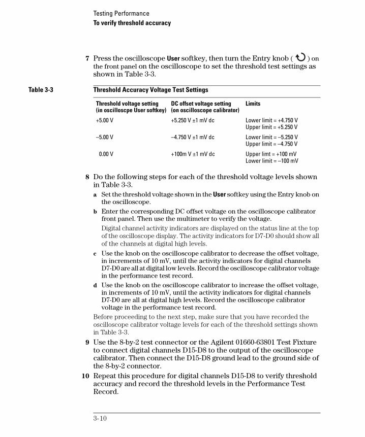
7 Press the oscilloscope User softkey, then turn the Entry knob ( ) on the front panel on the oscilloscope to set the threshold test settings as shown in Table 3-3.
Table 3-3 Threshold Accuracy Voltage Test Settings
8 Do the following steps for each of the threshold voltage levels shown in Table 3-3.a Set the threshold voltage shown in the User softkey using the Entry knob on
the oscilloscope.b Enter the corresponding DC offset voltage on the oscilloscope calibrator
front panel. Then use the multimeter to verify the voltage.Digital channel activity indicators are displayed on the status line at the top of the oscilloscope display. The activity indicators for D7-D0 should show all of the channels at digital high levels.
c Use the knob on the oscilloscope calibrator to decrease the offset voltage, in increments of 10 mV, until the activity indicators for digital channels D7-D0 are all at digital low levels. Record the oscilloscope calibrator voltage in the performance test record.
d Use the knob on the oscilloscope calibrator to increase the offset voltage, in increments of 10 mV, until the activity indicators for digital channels D7-D0 are all at digital high levels. Record the oscilloscope calibrator voltage in the performance test record.
Before proceeding to the next step, make sure that you have recorded the oscilloscope calibrator voltage levels for each of the threshold settings shown in Table 3-3.
9 Use the 8-by-2 test connector or the Agilent 01660-63801 Test Fixture to connect digital channels D15-D8 to the output of the oscilloscope calibrator. Then connect the D15-D8 ground lead to the ground side of the 8-by-2 connector.
10 Repeat this procedure for digital channels D15-D8 to verify threshold accuracy and record the threshold levels in the Performance Test Record.
Threshold voltage setting(in oscilloscpe User softkey)
DC offset voltage setting(on oscilloscope calibrator)
Limits
+5.00 V +5.250 V ±1 mV dc Lower limit = +4.750 VUpper limit = +5.250 V
–5.00 V –4.750 V ±1 mV dc Lower limit = –5.250 VUpper limit = –4.750 V
0.00 V +100m V ±1 mV dc Upper limt = +100 mVLower limit = –100 mV
3-10

Testing PerformanceTo verify voltage measurement accuracy
service.book Page 11 Tuesday, February 13, 2001 2:59 PM
To verify voltage measurement accuracy
This test verifies the voltage measurement accuracy. In this test, you will measure the output of a power supply using dual cursors on the oscilloscope, and compare the results with the multimeter reading.
Test limits: ±2.0% of full scale ±1 LSB*
• Full scale is defined as 16 mV on the 1 mV/div range.
• Full scale on all other ranges is defined as 8 divisions times the V/div setting.
*1 LSB = 0.4% of full scale
Table 3-4 Equipment Required to Verify Voltage Measurement Accuracy
Do this procedure first for Channel 1. Then repeat the procedure for Channel 2.
1 Set up the oscilloscope. a Adjust the channel 1 position knob to place the baseline at approximately
0.5 division from the bottom of the display.
Equipment Critical Specifications Recommended Model/Part
Power supply 14 mV to 35 Vdc, 0.1 mV resolution
Fluke 5820A or Agilent 3245A
Digital multimeter Better than 0.01% accuracy Agilent 34401A
Cable BNC, Qty 2 Agilent 10503A
Shorting cap BNC Agilent 1250-0774
Adapter BNC (f) to banana (m) Agilent 1251-2277
Adapter BNC tee (m) (f) (f) Agilent 1250-0781
Blocking capacitor Agilent 10240B
3-11

Testing PerformanceTo verify voltage measurement accuracy
service.book Page 12 Tuesday, February 13, 2001 2:59 PM
b Set the Volts/Div setting to the value in the first line in Table 3-5.
Table 3-5 Settings Used to Verify Voltage Measurement Accuracy
c Press the Acquire key. Then press the Averaging softkey and set #Avgs to 64.Wait a few seconds for the measurement to settle.
2 Press the Cursors key, set the Mode softkey to Normal, then press the X Y softkey and select Y. Press the Y1 softkey, then use the Entry knob (labeled on the front panel) to set the Y1 cursor on the baseline of the signal.
Volts/Div Setting Power Supply Setting Test Limits5 V/Div 35 V 34.04 V to 35.96 V 2 V/Div 14 V 13.616 V to 14.384 V 1 V/Div 7 V 6.808 V to 7.192 V 0.5 V/Div 3.5 V 3.404 V to 3.596 V 0.2 V/Div 1.4 V 1.3616 V to 1.4384 V 0.1 V/Div 700 mV 680.8 mV to 719.2 mV 50 mV/Div 350 mV 340.4 mV to 359.6 mV 20 mV/Div 140 mV 136.16 mV to 143.84 mV 10 mV/Div 70 mV 68.08 mV to 71.92 mV 5 mV/Div 35 mV 34.04 mV to 35.96 mV 2 mV/Div 14 mV 13.616 mV to 14.384 mV 1 mV/Div* 7 mV 6.616 mV to 7.384 mV *Full scale is defined as 16 mV on the 1 mV/div range.
Full scale on all other ranges is defined as 8 divisions times the V/div setting.
3-12

Testing PerformanceTo verify voltage measurement accuracy
service.book Page 13 Tuesday, February 13, 2001 2:59 PM
3 Use the BNC tee and cables to connect the oscilloscope calibrator /power supply to both the oscilloscope and the multimeter.
4 Adjust the output so that the multimeter reading displays the first Volts/div supply setting value in Table 3-5.Wait a few seconds for the measurement to settle.
5 Press the Y2 softkey, then position the Y2 cursor to the center of the waveform using the Entry knob. The ∆Y value on the lower line of the display should be within the test limits of Table 3-5. If a result is not within the test limits, see the “Troubleshooting” chapter. Then return here.
6 Continue to check the voltage measurement accuracy with the remaining Volts/div setting values in Table 3-5.
7 When you are finished checking all of the power supply setting values, disconnect the power supply from the oscilloscope.
8 Repeat this procedure for Channels 2, 3, and 4, if applicable on your oscilloscope model.
Figure 3-5
Using a Blocking Capacitor to Reduce Noise
Use a Blocking Capacitor to Reduce Noise
On the more sensitive ranges, such as 1 mV/div, 2 mV/div, and 5 mV/div, noise may be a factor. To eliminate the noise, use a BNC Tee, blocking capacitor, and BNC short to shunt the noise to ground. See figure 3-5.
To oscilloscope input
BNC short
Blocking Capacitor
To Power Supply or Calibrator
3-13

Testing PerformanceTo verify bandwidth
service.book Page 14 Tuesday, February 13, 2001 2:59 PM
To verify bandwidth
This test verifies bandwidth. In this test you will use an oscilloscope calibrator with a level sinewave output.
You will use the peak-to-peak voltage at both 1 MHz and 100 MHz to verify the bandwidth response of the oscilloscope.
54622A, 54622D, and 54624A
Test limits at 1 mV/div to 5 V/div:
• All channels (±3 dB)
• dc to 100 MHz
• ac coupled 10 Hz to 100 MHz
54621A and 54621D
Test limits at 1 mV/div to 5 V/div:
• All channels (±3 dB)
• dc to 60 MHz
• ac coupled 10 Hz to 60 MHz
Table 3-6 Equipment Required to Verify Bandwidth
Equipment Critical Specifications Recommended Model/Part
Oscilloscope Calibrator Fluke 5820A
Cable * Type N (m), 24-inch Agilent 11500B
Feedthrough 50Ω, BNC (m) and (f) Agilent 11048C
* The oscilloscope calibrator is supplied with 2 or more coaxial cables N (m), BNC (m), 1 meter long, Fluke P/N 686318.
3-14
Testing PerformanceTo verify bandwidth
service.book Page 15 Tuesday, February 13, 2001 2:59 PM
1 Connect the oscilloscope calibrator output through a 50 Ω feedthrough to the oscilloscope channel 1 input.
2 Set up the oscilloscope.a Set the time base to 500 ns/div.b Set the Volts/Div for channel 1 to 200 mV/div.c Press the Acquire key, then press the Averaging softkey.d Turn the Entry knob to set # Avgs to 8 averages.
3 Set the calibrator to “Level Sine” and OPR/STBY to “OPR”.4 Set the calibrator for 1 MHz and six divisions of amplitude.5 Press Autoscale on the oscilloscope.6 Press the Quick Meas key, then press the Peak-Peak softkey.
Wait a few seconds for the measurement to settle (averaging is then complete). View the Pk-Pk reading at the bottom of the display.
Record the reading: Vp-p = _______ V.
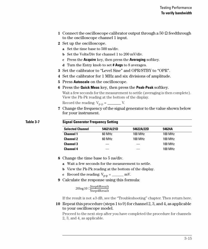
7 Change the frequency of the signal generator to the value shown below for your instrument.
Table 3-7 Signal Generator Frequency Setting
8 Change the time base to 5 ns/div.a Wait a few seconds for the measurement to settle.b View the Pk-Pk reading at the bottom of the display.c Record the reading: Vp-p = ______ mV.
9 Calculate the response using this formula:
If the result is not ±3 dB, see the “Troubleshooting” chapter. Then return here.
10 Repeat this procedure (steps 1 to 9) for channel 2, 3, and 4, as applicable to your oscilloscope model.Proceed to the next step after you have completed the procedure for channels 2, 3, and 4, as applicable.
Selected Channel 54621A/21D 54622A/22D 54624AChannel 1 60 MHz 100 MHz 100 MHzChannel 2 60 MHz 100 MHz 100 MHzChannel 3 — — 100 MHzChannel 4 — — 100 MHz
20 10logStep6ResultStep4Result--------------------------------⋅
3-15

Testing PerformanceTo verify horizontal Dt and 1/Dt accuracy
service.book Page 16 Tuesday, February 13, 2001 2:59 PM
To verify horizontal ∆t and 1/∆t accuracy
This test verifies the horizontal ∆t and 1/∆t accuracy. In this test, you will use the oscilloscope to measure the output of a time mark generator.
Test limits: ±0.01% of reading ±0.1% of full scale ±40 ps (same channel)
Table 3-8 Equipment Required to Verify Horizontal ∆t and 1/∆t Accuracy
1 Connect the oscilloscope calibrator to channel 1 using the 50 Ω feedthrough at the oscilloscope input. Then, select Marker and set the calibrator for 0.1 ms markers.
2 Set up the oscilloscope.a Press the Display key, then set the Vectors softkey to off. b Press the Autoscale key.c Set the time base to 20 µs/div. d Press the Main/Delayed key, then set the Time Ref softkey to Left. e Adjust the Trigger Level knob to obtain a stable display.
3 Press the Quick Meas softkey, set the Source softkey to 1, then press the Frequency softkey and the Period softkey. Measure the following:
Frequency 10 kHz — The test limits are 9.98 kHz to 10.02 kHz.
Period 100 µs — The test limits are 99.79 µs to 100.21 µs.
If the measurements are not within the test limits, see the “Troubleshooting” chapter. Then return here.
Equipment Critical Specifications Recommended Model/Part
Oscilloscope Calibrator Stability 5 ppm after 1/2 hour Fluke 5820A
Cable BNC, 3 feet Agilent 10503A
Termination 50Ω, BNC connectors (m) and (f) Agilent 11048C
3-16
Testing PerformanceTo verify horizontal Dt and 1/Dt accuracy
service.book Page 17 Tuesday, February 13, 2001 2:59 PM
4 Change the calibrator to 1-µs markers. Change the time base to 200 ns/div. Adjust the trigger level to obtain a stable display.
5 Measure the following:Frequency 1 MHz — The test limits are 997.9 kHz to 1.0021 MHz.
Period 1 µs — The test limits are 997.9 ns to 1.0021 µs.
If the measurements are not within the test limits, see the “Troubleshooting” chapter. Then return here.
54622A/22D/24A only6 Change the calibrator to 10-ns markers. Change the time base to
5 ns/div. Adjust the trigger level to obtain a stable display.7 Measure the following:
Frequency 100 MHz — The test limits are 99.09 MHz to 100.92 MHz.
Period 10 ns — The test limits are 9.91 ns to 10.09 ns.
If the measurements are not within the test limits, see the “Troubleshooting” chapter. Then return here.
54621A and 54621D only
8 Change the calibrator to 20 ns markers. Change the time base to 5 ns/div. Adjust the trigger level to obtain a stable display.
9 Measure the following:Frequency ,50 MHz — The test limits are 49.77 MHz to 50.23 MHz.
Period 20 ns — The test limits are 19.91 ns to 20.09 ns.
If the measurements are not within the test limits, see the “Troubleshooting” chapter. Then return here.
3-17

Testing PerformanceTo verify trigger sensitivity
service.book Page 18 Tuesday, February 13, 2001 2:59 PM
To verify trigger sensitivity
This test verifies the trigger sensitivity. In this test, you will apply 25 MHz to the oscilloscope. You will then decrease the amplitude of the signal to the specified levels, and check to see if the oscilloscope is still triggered. You will then repeat the process at the upper bandwidth limit.
Test limits for the Internal trigger:
1 mV to 5 V/div (dc to max bandwidth): greater of 0.35 div or 2.5 mVp-p
Test limits for the External trigger:
dc to 25 MHz: <75 mVp-p
25 MHz to max bandwidth: <150 mVp-p
Table 3-9 Equipment Required to Verify Trigger Sensitivity
Equipment Critical Specifications Recommended Model/Part
Oscilloscope Calibrator 25-MHz, 60-MHz and 100-MHz sine waves
Fluke 5820A
Power splitter Outputs differ < 0.15 dB Agilent 11667B
Cable * BNC, Qty 3 Agilent 10503A
Adapter N (m) to BNC (f), Qty 3 Agilent 1250-0780
Feedthrough 50Ω, BNC connectors (m) and (f) Agilent 11048C (2 required)
* The oscilloscope calibrator is supplied with 2 or more coaxial cables N (m), BNC (m), 1 meter long, Fluke P/N 686318.
3-18

Testing PerformanceTo verify trigger sensitivity
service.book Page 19 Tuesday, February 13, 2001 2:59 PM
Test Internal Trigger Sensitivity
1 Press the Save/Recall key, then press the Default Setup softkey. 2 Connect the calibrator to channel 1 using a 50 Ω feedthrough at the
oscilloscope input. 3 Verify the trigger sensitivity at 25 MHz and 0.35 divisions.
a Set the output of the calibrator to 25 MHz, and set the amplitude to about 100 mVp-p.
b Press the Autoscale key.c Set the time base to 50 ns/div. d Set channel 1 to 100 mV/div. e Decrease the output of the calibrator until 0.35 vertical divisions of the
signal are displayed. The trigger should be stable. If the trigger is not stable, try adjusting the trigger level. If adjusting the trigger level makes the trigger stable, the test still passes. If adjusting the trigger does not help, see the “Troubleshooting” chapter. Then return here.
f Record the result as Pass or Fail in the Performance Test Record.
4 Verify the trigger sensitivity at maximum bandwidth and 1 division.a Change the output of the calibrator to 100 MHz for the 54622A/22D/24A or
60 MHz or the 54621A/21D, and set the amplitude to about 100 mVp-p. b Set the time base to 10 ns/div. c Decrease the output of the calibrator until 1 vertical division of the signal
is displayed. The trigger should be stable. If the trigger is not stable, try adjusting the trigger level. If adjusting the trigger level makes the trigger stable, the test still passes. If adjusting the trigger does not help, see the “Troubleshooting” chapter. Then return here.
d Record the result as Pass or Fail in the Performance Test Record.
5 Repeat this procedure for channels 2, 3, and 4, as applicable to your oscilloscope model.
3-19

Testing PerformanceTo verify trigger sensitivity
service.book Page 20 Tuesday, February 13, 2001 2:59 PM
Test External Trigger Sensitivity
Verify the external trigger sensitivity at these settings:
100 MHz (54622A/22D/24A), <150 mVp-p
60 MHz (54621A/21D), <150 mVp-p
25 MHz (All models), <75 mVp-p
1 Use the power splitter to connect the calibrator to both the channel 1 input and the external trigger input. The Ext Trigger input is on the rear panel of the mixed-signal oscilloscope and the 4-channel oscilloscope. Connect 50Ω feedthroughs to the oscilloscope inputs.
2 Change the output of the calibrator to 100 MHz for the 54622A/22D/24A or 60 MHz for the 54621A/21D, and set the amplitude to 106 mVrms (300 mVp-p). The power splitter divides the 300 mVp-p so that 150 mVp-p is applied to each of the oscilloscope inputs.
3 Press the Autoscale key.4 Press the Trigger Edge key, then press the Ext softkey to set the trigger
source to external trigger. 5 Check for stable triggering, and adjust the trigger level if necessary. 6 Record the results as Pass or Fail in the Performance Test Record.
If the test fails, see the “Troubleshooting” chapter. Then return here.
7 Change the output of the calibrator to 25 MHz and set the amplitude to 25.74 mVrms (75 mVp-p).
8 Check for stable triggering, and adjust the trigger level if necessary. 9 Record the results as Pass or Fail in the Performance Test Record.
If the test fails, see the “Troubleshooting” chapter. Then return here.
3-20

service.book Page 21 Tuesday, February 13, 2001 2:59 PM
Agilent 54622A/22D/24A Performance Test Record
Agilent 54622A/54622D/54624A
Serial No. ______________________________________ Test by _____________________________Test Interval ____________________________________ Work Order No. ______________________Recommended Next Testing ________________________ Temperature ____________
Threshold Specification Limits Ch D7-D0 Ch D15-D8 Accuracy Test 5 V - 250 mV 4.750 V ________ ________(100 mV + 3% of threshold setting)
5 V + 250 mV 5.250 V ________ ________-5 V - 250 mV -5.250 V ________ ________-5 V + 250 mV -4.750 V ________ ________0 V - 100 mV -100 mV ________ ________0 V + 100 mV 100 mV ________ ________
Voltage Measurement AccuracyRange Power Supply Setting Test Limits Channel 1 Channel 2 Channel 3 Channel 45 V/Div 35 V 34.04 V to 35.96 V ________ ________ ________ ________2 V/Div 14 V 13.616 V to 14.384 V ________ ________ ________ ________1 V/Div 7 V 6.808 V to 7.192 V ________ ________ ________ ________500 mV/Div 3.5 V 3.404 V to 3.596 V ________ ________ ________ ________200 mV/Div 1.4 V 1.3616 V to 1.4384 V ________ ________ ________ ________100 mV/Div 700 mV 680.8 mV to 719.2 mV ________ ________ ________ ________50 mV/Div 350 mV 340.4 mV to 359.6 mV ________ ________ ________ ________20 mV/Div 140 mV 136.16 mV to 143.84 mV ________ ________ ________ ________10 mV/Div 70 mV 68.08 mV to 71.92 mV ________ ________ ________ ________5 mV/Div 35 mV 34.04 mV to 35.96 mV ________ ________ ________ ________2 mV/Div 14 mV 13.616 mV to 14.384 mV ________ ________ ________ ________1 mV/Div 7 mV 6.616 mV to 7.384 mV ________ ________ ________ ________
Bandwidth Test Limits Channel 1 Channel 2 Channel 3 Channel 4 3 dB at 100 MHz ________ ________ ________ ________
Horizontal ∆t and 1/∆t AccuracyGenerator Setting Test Limits Results
Frequency 10 kHz 9.98 kHz to 10.02 kHz ________Period 100 µs 99.79 µs to 100.21 µs ________Frequency 1 MHz 997.9 kHz to 1.0021 MHz ________Period 1 µs 997.9 ns to 1.0021 µs ________Frequency 100 MHz 99.09 MHz to 101.92 MHz ________Period 10 ns 9.91 ns to 10.09 ns ________
Trigger Sensitivity Test Limits Channel 1 Channel 2 Channel 3 Channel 4Internal trigger 25 MHz at 0.35 divisions ________ ________ ________ ________
100 MHz at 1 division ________ ________ ________ _______Ext
External trigger 25 MHz at <75 mVp-p ________100 MHz at <150 mVp-p ________
3-21

service.book Page 22 Tuesday, February 13, 2001 2:59 PM
Agilent 54621A/21D Performance Test Record
Agilent 54621A/54621D
Serial No. ______________________________________ Test by _____________________________Test Interval ____________________________________ Work Order No. ______________________Recommended Next Testing ________________________ Temperature ____________
Threshold Specification Limits Ch D7-D0 Ch D15-D8 Accuracy Test 5 V - 250 mV 4.750 V ________ ________(100 mV + 3% of threshold setting)
5 V + 250 mV 5.250 V ________ ________-5 V - 250 mV -5.250 V ________ ________-5 V + 250 mV -4.750 V ________ ________0 V - 100 mV -100 mV ________ ________0 V + 100 mV 100 mV ________ ________
Voltage Measurement AccuracyRange Power Supply Setting Test Limits Channel 1 Channel 2 Channel 3 Channel 45 V/Div 35 V 34.04 V to 35.96 V ________ ________ ________ ________2 V/Div 14 V 13.616 V to 14.384 V ________ ________ ________ ________1 V/Div 7 V 6.808 V to 7.192 V ________ ________ ________ ________500 mV/Div 3.5 V 3.404 V to 3.596 V ________ ________ ________ ________200 mV/Div 1.4 V 1.3616 V to 1.4384 V ________ ________ ________ ________100 mV/Div 700 mV 680.8 mV to 719.2 mV ________ ________ ________ ________50 mV/Div 350 mV 340.4 mV to 359.6 mV ________ ________ ________ ________20 mV/Div 140 mV 136.16 mV to 143.84 mV ________ ________ ________ ________10 mV/Div 70 mV 68.08 mV to 71.92 mV ________ ________ ________ ________5 mV/Div 35 mV 34.04 mV to 35.96 mV ________ ________ ________ ________2 mV/Div 14 mV 13.616 mV to 14.384 mV ________ ________ ________ ________1 mV/Div 7 mV 6.616 mV to 7.384 mV ________ ________ ________ ________
Bandwidth Test Limits Channel 1 Channel 2 3 dB at 60 MHz ________ ________
Horizontal ∆t and 1/∆t AccuracyGenerator Setting Test Limits Results
Frequency 10 kHz 9.98 kHz to 10.02 kHz ________Period 100 µs 99.79 µs to 100.21 µs ________Frequency 1 MHz 997.9 kHz to 1.0021 MHz ________Period 1 µs 997.9 ns to 1.0021 µs ________Frequency 50 MHz 49.77 MHz to 50.23 MHz ________Period 20 ns 19.91 ns to 20.09 ns ________
Trigger Sensitivity Test Limits Channel 1 Channel 2 Internal trigger 25 MHz at 0.35 divisions ________ ________
60 MHz at 1 division ________ ________Ext
External trigger 25 MHz at <75 mVp-p ________60 MHZ at <150 mVp-p ________
3-22

service.book Page 1 Tuesday, February 13, 2001 2:59 PM
4
Calibrating and Adjusting

service.book Page 2 Tuesday, February 13, 2001 2:59 PM
Calibrating and Adjusting
This chapter explains how to adjust the oscilloscope for optimum operating performance. You should perform the hardware adjustments and self-calibration according to the following recommendations.
• Perform hardware adjustments every 12 months or after 2,000 hours of operation.
• Perform self-calibration:• every 6 months or after 1000 hours of operation
• if the ambient temperature is >10 °C from the calibration temperature
• if you want to maximize the measurement accuracy
The amount of use, environmental conditions, and experience with other instruments help determine if you need shorter adjustment intervals.
In this chapter, you will:
• Adjust the power supply
• Perform self-calibration• Adjust the low-frequency compensation
• Adjust the high-frequency pulse response
• Adjust the display
Let the Equipment Warm Up Before Adjusting
Before you start the adjustments, let the oscilloscope and test equipment warm up for at least 30 minutes.
Read All Cautions and Warnings
Read the following cautions and warning before making adjustments or performing self-calibration.
4-2

Calibrating and Adjusting
service.book Page 3 Tuesday, February 13, 2001 2:59 PM
W A R N I N G HAZARDOUS VOLTAGES !
Read the safety summary at the back of this book before proceeding.
Maintenance is performed with power supplied to the oscilloscope and with the protective covers removed. Only trained service personnel who are aware of the hazards involved should perform the maintenance. Whenever possible, perform the procedures with the power cord removed from the oscilloscope.
C A U T I O N REMOVE POWER TO AVOID DAMAGE !
Do not disconnect any cables or remove any assemblies with power applied to the oscilloscope. Otherwise, damage to the oscilloscope can occur.
C A U T I O N USE EXTERNAL FAN TO REDUCE TEMPERATURE !
When you must operate the oscilloscope with its cover removed, use an external fan to provide continuous air flow over the samplers. Air flow over the samplers is reduced when the cover is removed, which leads to higher than normal operating temperatures. Have the fan blow air across the system PC board where the heat sinks are located.
C A U T I O N AVOID DAMAGE TO ELECTRONIC COMPONENTS !
Electrostatic discharge (ESD) can damage electronic components. When you use any of the procedures in this chapter, use proper ESD precautions. As a minimum, place the oscilloscope on a properly grounded ESD mat and wear a properly grounded ESD strap.
4-3

Calibrating and AdjustingTo adjust the power supply
service.book Page 4 Tuesday, February 13, 2001 2:59 PM
To adjust the power supply
The oscilloscope power supply has both a +3.3 V adjustment, and a +5.1 V / -5.2 V balance adjustment. Other oscilloscope voltages are based on the +3.3 V adjustment.
In this procedure, you will use a digital multimeter to measure the +3.3 V and +5.1 V / -5.2 V test points, and adjust the power supplies to be within tolerance, if necessary.
Table 4-1 Equipment Required to Adjust the Power Supply
1 Prepare the oscilloscope for the voltage adjustment. a Turn off the oscilloscope and disconnect the power cable. b Remove the oscilloscope cover. For a list of parts, see the “Replaceable
Parts” chapter, then return here.c Place the oscilloscope on its side. d Connect the negative lead of the digital multimeter to a ground point on the
oscilloscope chassis. e Reconnect the power cable. f Turn on the oscilloscope.
Equipment Critical Specifications Recommended Model/Part
Digital multimeter 0.1 mV resolution, accuracy ±0.05% Agilent 34401A
4-4
Calibrating and AdjustingTo adjust the power supply
service.book Page 5 Tuesday, February 13, 2001 2:59 PM
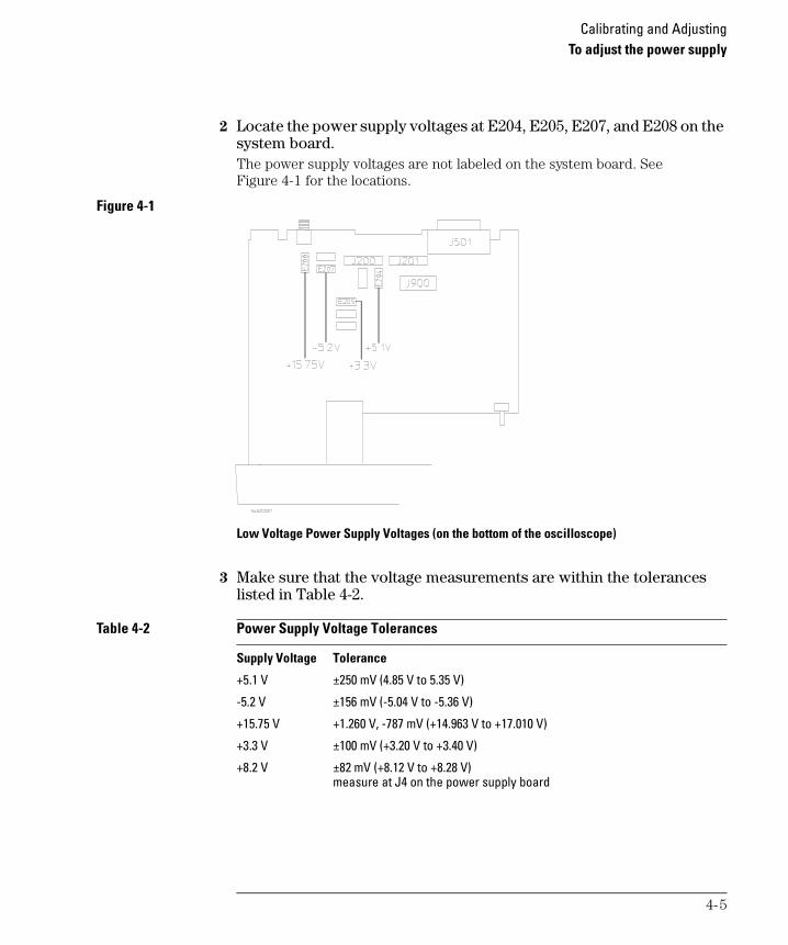
2 Locate the power supply voltages at E204, E205, E207, and E208 on the system board. The power supply voltages are not labeled on the system board. See Figure 4-1 for the locations.
Figure 4-1
Low Voltage Power Supply Voltages (on the bottom of the oscilloscope)
3 Make sure that the voltage measurements are within the tolerances listed in Table 4-2.
Table 4-2 Power Supply Voltage Tolerances
Supply Voltage Tolerance
+5.1 V ±250 mV (4.85 V to 5.35 V)
-5.2 V ±156 mV (-5.04 V to -5.36 V)
+15.75 V +1.260 V, -787 mV (+14.963 V to +17.010 V)
+3.3 V ±100 mV (+3.20 V to +3.40 V)
+8.2 V ±82 mV (+8.12 V to +8.28 V) measure at J4 on the power supply board
4-5

Calibrating and AdjustingTo adjust the power supply
service.book Page 6 Tuesday, February 13, 2001 2:59 PM
4 If the +5.1 V measurement is out of tolerance, adjust the +5.1 V / -5.2 V balance adjustment on the power supply. See Figure 4-2.
5 If the -5.2 V measurement is out of tolerance, adjust the +5.1 V / -5.2 V balance adjustment on the power supply. See Figure 4-2.The +15.75 V supply is not adjustable, and is dependent upon the +5.1 V supply.
Figure 4-2
Low Voltage Power Supply Adjustments (on the top of the oscilloscope)
6 If adjusting the power supply does not bring all the voltages within tolerance, go to the “Troubleshooting” chapter.
+5.1 / -5.2 VBalance Adjustment
E2 and E38.5 V DC
Fan Connector Printer Power
+3.3V Adjustment
4-6

Calibrating and AdjustingTo perform User Cal
service.book Page 7 Tuesday, February 13, 2001 2:59 PM
To perform User Cal
User Cal performs an internal self-alignment routine to optimize the signal path in the oscilloscope. The routine uses internally generated signals to optimize circuits that affect channel sensitivity, offset, and trigger parameters. Disconnect all inputs and allow the oscilloscope to warm up before performing this procedure.
User Cal should be performed at least once a year, any time the ambient temperature of the oscilloscope has changed more than 10 °C since the last User Cal, or after any repair.
Performing User Cal will not invalidate your Certificate of Calibration. Successful completion of User Cal does not certify this oscilloscope with a National Institute of Standards and Technology (NIST) calibration.
1 Disconnect all inputs signals from the oscilloscope2 Set the rear-panel CALIBRATION switch to UNPROTECTED.3 Press the Utility key, then press the Service softkey.4 Begin the Self Cal by pressing the User Cal softkey.5 When the User Cal is completed, set the rear-panel CALIBRATION switch
to PROTECTED.
4-7

Calibrating and AdjustingTo adjust the oscilloscope display
service.book Page 8 Tuesday, February 13, 2001 2:59 PM
To adjust the oscilloscope display
In this procedure, you will make adjustments using two display patterns.
Table 4-3 Equipment Required to Adjust the Oscilloscope Display
1 Connect the digital multimeter to the end of R901, located closest to the fuse, as shown in Figure 4-3.
2 Adjust +B.ADJ for +14.00 V. In the remainder of this procedure, you will make adjustments to:
3 Adjust V.HOLD (vertical hold) for vertical synchronization.4 Set the INTENSITY control (lower-left on the front panel) to
approximately 50%.
When to Adjust the Oscilloscope Display
The oscilloscope display normally does not require adjustment. However, when it is obvious that the display is out of adjustment, use this optional procedure.
Equipment Critical Specifications Recommended Model/Part
Digital multimeter Accuracy ±0.05,% 1 mV resolution Agilent 34401A
V.HOLD (vertical hold)INTENSITY (intensity control on oscilloscope front panel)H.HOLD (horizontal hold)FOCUSV.LIN (vertical linearity)V.SIZE (vertical size)
Do not adjust Sub Bri or Cont controls
Do not adjust the SUB BRT (sub bright) or CONTRAST Controls. These controls are preset at the factory to assure the correct number of display grayscales.
4-8

Calibrating and AdjustingTo adjust the oscilloscope display
service.book Page 9 Tuesday, February 13, 2001 2:59 PM
5 Adjust H.HOLD (horizontal hold) to center the display horizontally.6 Adjust FOCUS to achieve the best focus.7 Adjust V.LIN (vertical linearity) to position all four corners of the half-
bright borders equally.8 Adjust V.SIZE (vertical size) to center the display vertically at the
maximum allowable size without losing the half-bright borders.Because V.LIN and V.SIZE interact with each other, you may need to re-adjust the sizing and vertical centering of the pattern on the display.
Figure 4-3
Oscilloscope Display Board Adjustments
4-9

service.book Page 10 Tuesday, February 13, 2001 2:59 PM
4-10

service.book Page 1 Tuesday, February 13, 2001 2:59 PM
5
Troubleshooting

service.book Page 2 Tuesday, February 13, 2001 2:59 PM
Troubleshooting
This chapter begins with suggestions for solving general problems that you may encounter with the oscilloscope. It tells you what to do in these cases:
• If there is no trace display
• If the trace display is unusual or unexpected• If you cannot see a channel
• If you cannot get any response from the oscilloscope
Procedures for troubleshooting the oscilloscope follow the problem solving suggestions. The troubleshooting section shows you how to:
• Check out the oscilloscope• Clear error messages from the display
• Check the low voltage power supply
• Run internal self-tests
Using the Dummy Load
Before you begin troubleshooting, you must either already have the dummy load that is mentioned, or you must construct one, as described in this chapter. You will use this dummy load while troubleshooting.
Read All Cautions and Warnings
Before you begin any troubleshooting, read all Warning and Cautions in the “Troubleshooting” section.
5-2

service.book Page 3 Tuesday, February 13, 2001 2:59 PM
Solving General Problems with the Oscilloscopes
This section describes how to solve general problems that you may encounter while using the 54621A/22A/24A Oscilloscopes and the 54621D/22D Mixed-Signal Oscilloscopes to make measurements.
After troubleshooting the oscilloscope, if you need to replace parts, refer to the “Replaceable Parts” chapter.
If there is no trace display
Check that the power cord is connected to the oscilloscope and to a live power source.
Check that the front-panel power switch is set to 1 (on).
Check that the display is illuminated and that the INTENSITY knob is adjusted correctly.
If there is no display, go to the troubleshooting procedures in this chapter.
Check that the oscilloscope probe lead wires are securely inserted into the connector assembly and that the probe clips make good contact with the probe lead wires.
Check that the probe clips are securely connected to points in the circuit under test, and that the ground is connected.
Check that the circuit under test is powered on.
Press the Autoscale key.
Reset the oscilloscope.
• To reset the entire oscilloscope, press and hold any softkey and switch the oscilloscope power on. Release the softkey when the display appears.
Obtain service from Agilent Technologies, if necessary.
5-3

TroubleshootingIf the trace display is unusual or unexpected
service.book Page 4 Tuesday, February 13, 2001 2:59 PM
If the trace display is unusual or unexpected
Check that the Horizontal time/division setting is correct for the expected frequency range of the input signals.
The sampling speed of the oscilloscope depends on the time/division setting. It may be that when the time/division setting is slower than 1 ms/div, the oscilloscope is sampling too slowly to capture all of the transitions on the waveform.
Check that all oscilloscope probes are connected to the correct signals in the circuit under test.
Check to see that the ground lead on the cable is securely connected to ground in the circuit under test. For high-speed measurements, each probe’s individual ground lead should also be connected to a ground point closest to the signal point in the circuit under test.
Use chapter 2 for information on probing considerations.
Check that the trigger setup is correct.
A correct trigger setup is the most important factor in helping you capture the data you desire. See the User’s Guide for information about triggering.
Check that infinite persistence in the Display menu is turned off, then press the Clear Display softkey.
Press the Autoscale key.
5-4

TroubleshootingIf you cannot see a channel
service.book Page 5 Tuesday, February 13, 2001 2:59 PM
If you cannot see a channel
Check that the oscilloscope probe cable is securely connected to the input connector.
Check that the oscilloscope probe lead wires are securely inserted into the connector assembly and that the probe clips make good contact with the probe lead wires.
Check that the probe clips are securely connected to points in the circuit under test.
Check that the circuit under test is powered on.
You may have pressed the Autoscale key before an input signal was available.
Performing the checks listed here ensures that the signals from the circuit under test will be seen by the oscilloscope. Perform the remaining checks in this topic to make sure the oscilloscope channels are on, and to obtain an automatic setup.
Check that the desired oscilloscope channels are turned on.
a Press the analog channel key until it is illuminated.b Press the digital channel group key (D15 Thru D8 or D7 Thru D0 keys) until it
is illuminated. Use the Entry knob or Channel Select knob to scroll through the digital channels to make sure that the desired channels are turned on.
Press the Autoscale key to automatically set up all channels.
5-5

service.book Page 6 Tuesday, February 13, 2001 2:59 PM
Troubleshooting the Oscilloscope
The service policy for the 54621A/22A/24A Oscilloscopes and the 54621D/22D Mixed-Signal Oscilloscopes is instrument replacement. Please call (877) 447-7278 to return the defective instrument, and Agilent Technologies will expedite a refurbished instrument to you under the Agilent Express Exchange program.
W A R N I N G HAZARDOUS VOLTAGES EXIST — REMOVE POWER FIRST !
The maintenance described in this section is performed with power supplied to the oscilloscope and with the protective covers removed. Only trained service personnel who are aware of the hazards involved should perform the maintenance. Whenever possible, perform the procedures with the power cord removed from the oscilloscope. Read the safety summary at the back of this book before proceeding.
C A U T I O N REMOVE POWER TO AVOID DAMAGE !
Do not disconnect any cables or remove any assemblies while power is applied to the oscilloscope, or damage to the oscilloscope can occur.
C A U T I O N AVOID ESD DAMAGE TO COMPONENTS !
ELECTROSTATIC DISCHARGE (ESD) can damage electronic components. Use proper ESD precautions when doing any of the procedures in this chapter. As a minimum, place the oscilloscope on a properly grounded ESD mat and wear a properly grounded ESD strap.
Equipment required for troubleshooting
The equipment listed in Table 5-1 is required to troubleshoot the oscilloscope.
Table 5-1 Equipment Required to Troubleshoot the Oscilloscope
Equipment Critical Specifications Recommended Model/Part
Digital multimeter Accuracy ±0.05,% 1 mV resolution Agilent 34401A
Oscilloscope 100 MHz, 1 MΩ input R Agilent 54600B
Dummy load Compatible with power supply See “To construct your own dummy load” on page 5-7.
5-6

TroubleshootingTo construct your own dummy load
service.book Page 7 Tuesday, February 13, 2001 2:59 PM
To construct your own dummy load
1 Obtain a connector that is compatible with the connector J3 on the Low Voltage Power Supply.
2 Connect load resistors to the connector as follows:
Figure 5-1
Location of the Low Voltage Power Supply Connectors
Connector Load (Amps) Resistor Watts Connect to Pin Ground to Pin+5.1 V 4.4 A 1.2 Ω 22 W 10, 11, 12 13, 14-5.2 V 1.6 A 3.25 Ω 8 W 4, 5 6+15.75 V 1.2 A 13.1 Ω 20 W 1 2+3.3 V 4 A 0.825 Ω 13 W 15, 16, 17, 18 19, 20
+5.1 / -5.2 VBalance Adjustment
E2 and E38.5 V DC
Fan Connector Printer Power
+3.3V Adjustment
5-7

TroubleshootingTo check out the oscilloscope
service.book Page 8 Tuesday, February 13, 2001 2:59 PM
To check out the oscilloscope
1 Is an interface module connected to the rear panel of the oscilloscope? If the answer is yes, follow these steps. Otherwise, go to step 2. a Turn off the oscilloscope. b Remove the interface module. c Turn on the oscilloscope, then check for the failing symptom.d If the failing symptom is not present, replace the interface module. e If the failing symptom is still present, go to step 2.
2 Disconnect any external cables from the front panel. 3 Disconnect the power cord, then remove the cabinet.
C A U T I O N USE AN EXTERNAL FAN TO AVOID OVERHEATING COMPONENTS !
If you operate the oscilloscope with the cabinet removed, you must use an external fan to blow air across the system board. This external air flow is necessary to cool the heat sinks on the system board. Otherwise, damage to the components can occur.
4 Connect the power cord, then turn on the oscilloscope.• If the oscilloscope display comes on after a few seconds, you will need to
check the low voltage power supply. Go to “To check the Low Voltage Power Supply” on page 5-11. Then return here.
• If, after checking the low voltage power supply, the voltages are within the test limits, go to step 8. If they are not within the test limits, go to step 6.
If the display did not come on, follow these steps:
a Disconnect the power cord.b Check to verify that all of the cable connections are secure.c Check the low voltage power supply. Go to “To check the Low Voltage
Power Supply” on page 5-11.If the voltages are within the limits go to step 5. If the voltages are not within the limits, go to step 6.
5-8

TroubleshootingTo check out the oscilloscope
service.book Page 9 Tuesday, February 13, 2001 2:59 PM
5 Disconnect the display ribbon cable from the system board. Then check the signals on the system board listed in Table 5-2.
Table 5-2 Display Signals on the System Board – All Oscilloscopes
If the signals are good, replace the display assembly.
If the signals are not good, replace the system board.
6 Disconnect the ribbon cable from the display board. 7 Check the low voltage power supply. Go to “To check the Low Voltage
Power Supply” on page 5-11.If the voltages are within the test limits, replace the display assembly.
If the voltages are not within the test limits, follow these steps:
a Disconnect the power cord. b Disconnect the ribbon cable from the power supply. c Connect the dummy load to the power supply connector. d Connect the power cord. Then measure the power supply voltages again.
See the new tolerances in Table 5-3.
Table 5-3 Low Voltage Power Supply Tolerances
If the voltages are within the test limits now, replace the system board.
If the voltages are still not within the test limits, replace the power supply.
Signal Name Frequency Pulse Width Voltage
J900 Pin 14 Hsync 19.72 kHz 3.0 ms 4.5 Vp-p
J900 Pin 13 Vsync 60.00 Hz 253.5 ms 4.5 Vp-p
Supply Voltage Tolerance
+5.1 V ±153 mV (+4.947 V to +5.253 V)
-5.2 V ±156 mV (-5.04 V to -5.36 V)
+15.75 V +1.260 V, -787 mV (+14.963 V to +17.010 V)
+3.3 V ±100 mV (+3.20 V to +3.40 V)
5-9
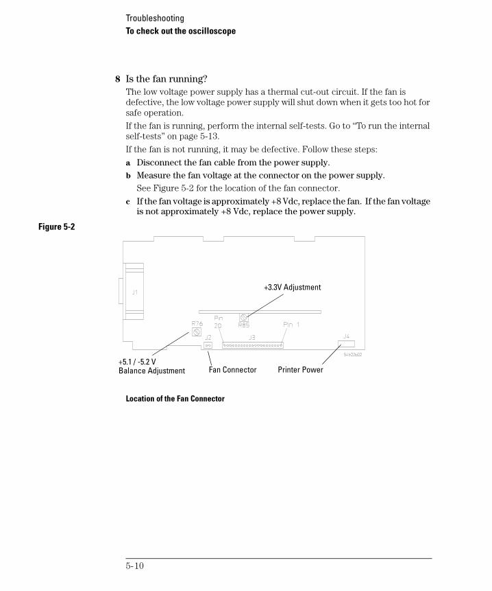
TroubleshootingTo check out the oscilloscope
service.book Page 10 Tuesday, February 13, 2001 2:59 PM
8 Is the fan running? The low voltage power supply has a thermal cut-out circuit. If the fan is defective, the low voltage power supply will shut down when it gets too hot for safe operation.
If the fan is running, perform the internal self-tests. Go to “To run the internal self-tests” on page 5-13.
If the fan is not running, it may be defective. Follow these steps:
a Disconnect the fan cable from the power supply. b Measure the fan voltage at the connector on the power supply.
See Figure 5-2 for the location of the fan connector.
c If the fan voltage is approximately +8 Vdc, replace the fan. If the fan voltage is not approximately +8 Vdc, replace the power supply.
Figure 5-2
Location of the Fan Connector
+5.1 / -5.2 VBalance Adjustment Fan Connector Printer Power
+3.3V Adjustment
5-10

TroubleshootingTo check the Low Voltage Power Supply
service.book Page 11 Tuesday, February 13, 2001 2:59 PM
To check the Low Voltage Power Supply
1 Disconnect the power cord from the oscilloscope. Then remove the oscilloscope cover and set the oscilloscope on its side.
C A U T I O N USE AN EXTERNAL FAN TO AVOID OVERHEATING COMPONENTS !
If you operate the oscilloscope with the cabinet removed, you must use an external fan to blow air across the system board. This external air flow is necessary to cool the heat sinks on the system board. Otherwise, damage to the components can occur.
2 Connect the negative lead of the multimeter to a ground point on the oscilloscope. Connect the power cord and turn on the oscilloscope.
3 Measure the power supply voltages at E1 through E6 on the system board. See Figure 5-3 and Table 5-4.
Figure 5-3
Low Voltage Power Supply Test Points
5-11

TroubleshootingTo check the Low Voltage Power Supply
service.book Page 12 Tuesday, February 13, 2001 2:59 PM
Table 5-4 Low Voltage Power Supply Tolerances
4 If the +5.1 V measurement is out of tolerance, adjust the +5.1 V adjustment on the power supply.
5 If the -5.2 V measurement is out of tolerance, adjust the -5.2 V adjustment on the power supply. The +15.75 V supply is not adjustable, and is dependent upon the +5.1 V supply.
C A U T I O N BEWARE OF HAZARDOUS VOLTAGES !
Be careful when performing component-level repair. Voltages greater than 300 Vdc exist, and can cause injury.
Supply Voltage Tolerance
+5.1 V ±153 mV (+4.947 V to +5.253 V)
-5.2 V ±156 mV (-5.04 V to -5.36 V)
+15.75 V +1.260 V, -787 mV (+14.963 V to +17.010 V)
+3.3 V ±100 mV (+3.20 V to +3.40 V)
If the Fuse is Blown
If the power supply fuse is blown, the power supply is defective, and you must replace it. See the “Replaceable Parts” chapter for information about removing the power supply.
5-12

TroubleshootingTo run the internal self-tests
service.book Page 13 Tuesday, February 13, 2001 2:59 PM
To run the internal self-tests
Self Test performs a series of internal procedures to verify that the oscilloscope and any attached module are operating properly.
It is recommended that you run the Self Test:
• after experiencing abnormal operation
• for additional information to better describe an oscilloscope failure
• to verify proper operation after the oscilloscope has been repaired
Successfully passing Self Test does not guarantee 100% of the oscilloscope’s functionality. Self Test is designed to provide an 80% confidence level that the oscilloscope is operating properly.
1 Press the Utility key, then press the Service softkey.2 Begin the internal self tests by pressing the Self Test softkey.
a The oscilloscope will display the message “Running self tests” on the screen.b The oscilloscope will then display one of the following messages on the
screen indicating the status of the self-tests:• Self Tests Passed.
• Self Tests Failed.
5-13

service.book Page 14 Tuesday, February 13, 2001 2:59 PM
5-14

service.book Page 1 Tuesday, February 13, 2001 2:59 PM
6
Replacing Assemblies
service.book Page 2 Tuesday, February 13, 2001 2:59 PM
Replacing Assemblies
This chapter describes how to remove assemblies from the oscilloscope. After you have removed an assembly, to install the replacement assembly, follow the instructions in reverse order.
The removable assemblies include:
• Cabinet• Fan
• Floppy Drive
• Front panel• Display
• System board
• Power supply• Keyboard
• Handle
Tools Used for Disassembly
Use these tools to remove and replace the oscilloscope assemblies:
• T15 TORX driver — to remove the oscilloscope from the cabinet and to remove the fan.
• T10 TORX driver — to remove the assemblies from the deck.
• Flat-blade screwdriver — to remove the front panel and power shaft, and the optional interface modules and pouch.
See how the Oscilloscope Parts Fit Together
An exploded view of the oscilloscope is included in the “Replaceable Parts” chapter. It shows the individual part numbers used in the assemblies, and shows you how the parts fit together.
Read All Warnings and Cautions
Read the following warnings and cautions before removing and replacing any assemblies in the oscilloscope.
6-2
Replacing Assemblies
service.book Page 3 Tuesday, February 13, 2001 2:59 PM
W A R N I N G HAZARDOUS VOLTAGES !
Read the safety summary at the back of this book before proceeding.
Maintenance is performed with power supplied to the oscilloscope and with the protective covers removed. Only trained service personnel who are aware of the hazards involved should perform the maintenance. Whenever possible, perform the procedures with the power cord removed from the oscilloscope.
W A R N I N G AVOID ELECTRICAL SHOCK !
Hazardous voltages exist on the CRT, power supply, and display sweep board. To avoid electrical shock:
1 Disconnect the power cord from the oscilloscope.2 Wait at least three minutes for the capacitors in the oscilloscope to
discharge before you begin disassembly.Read the Safety Summary at the back of this manual before you begin.
C A U T I O N REMOVE POWER TO AVOID DAMAGE !
Remove power before you begin to remove and replace assemblies. Do not remove or replace assemblies while the oscilloscope is turned on, or damage to the components can occur.
C A U T I O N AVOID DAMAGE TO ELECTRONIC COMPONENTS !
ELECTROSTATIC DISCHARGE (ESD) can damage electronic components. When doing any of the procedures in this chapter, use proper ESD precautions. As a minimum, you should place the instrument on a properly grounded ESD mat and wear a properly grounded ESD strap.
6-3

Replacing AssembliesTo remove the cabinet
service.book Page 4 Tuesday, February 13, 2001 2:59 PM
To remove the cabinet
1 Turn off the oscilloscope and disconnect the power cable. 2 If a module is installed, remove it from the oscilloscope. 3 Using the T15 TORX driver, remove the two screws from the rear of the
cabinet. 4 Using your thumbs, gently push on the rear-panel connector to slide the
oscilloscope out of the cabinet.
To remove the fan
1 Disconnect the fan cable from the power supply board. 2 Using the T15 TORX driver, remove the three screws that hold the fan
to the deck.
To remove the floppy drive
1 Using the T8 TORX driver, loosen the two screws that hold the drive to the deck.
2 Lift the drive away from the system board.3 Disconnect the ribbon cable from the connector on the rear of the drive.
6-4
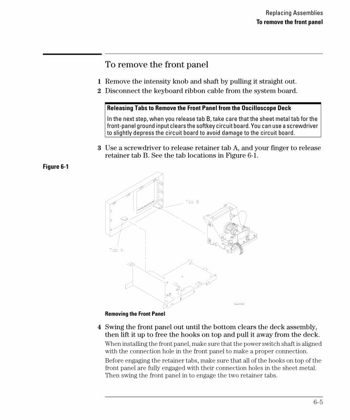
Replacing AssembliesTo remove the front panel
service.book Page 5 Tuesday, February 13, 2001 2:59 PM
To remove the front panel
1 Remove the intensity knob and shaft by pulling it straight out.2 Disconnect the keyboard ribbon cable from the system board.
3 Use a screwdriver to release retainer tab A, and your finger to release retainer tab B. See the tab locations in Figure 6-1.
Figure 6-1
Removing the Front Panel
4 Swing the front panel out until the bottom clears the deck assembly, then lift it up to free the hooks on top and pull it away from the deck.When installing the front panel, make sure that the power switch shaft is aligned with the connection hole in the front panel to make a proper connection.
Before engaging the retainer tabs, make sure that all of the hooks on top of the front panel are fully engaged with their connection holes in the sheet metal. Then swing the front panel in to engage the two retainer tabs.
Releasing Tabs to Remove the Front Panel from the Oscilloscope Deck
In the next step, when you release tab B, take care that the sheet metal tab for the front-panel ground input clears the softkey circuit board. You can use a screwdriver to slightly depress the circuit board to avoid damage to the circuit board.
6-5

Replacing AssembliesTo remove the display
service.book Page 6 Tuesday, February 13, 2001 2:59 PM
To remove the display
1 Remove the front panel from the oscilloscope. 2 Disconnect the ribbon cable and the calibration cable from the display. 3 Using the T10 TORX driver, remove the four screws that hold the display
to the deck. Set these screws aside.
C A U T I O N USE CORRECT SCREWS TO AVOID SHORTING SYSTEM BOARD !
When you re-install the display, you must re-insert the screws you removed in this step. If you re-insert screws that are longer, they can short the system board to ground.
4 Lift the display and remove it from the deck.
To remove the system board
1 Using the T10 TORX driver, remove the six screws that hold the system board to the deck.
2 Remove the two hex nuts and washers from the rear BNCs.3 Disconnect the three ribbon cables and the calibration cable.4 As you remove the system board, rotate it so that the BNCs clear the
front panel.
To remove the front-panel BNC connectors
1 Remove the system board. 2 De-solder the center conductor wire and the probe readout wire from
the board. 3 Using the T10 Torx driver, remove the screw holding the BNC to the
housing.
6-6
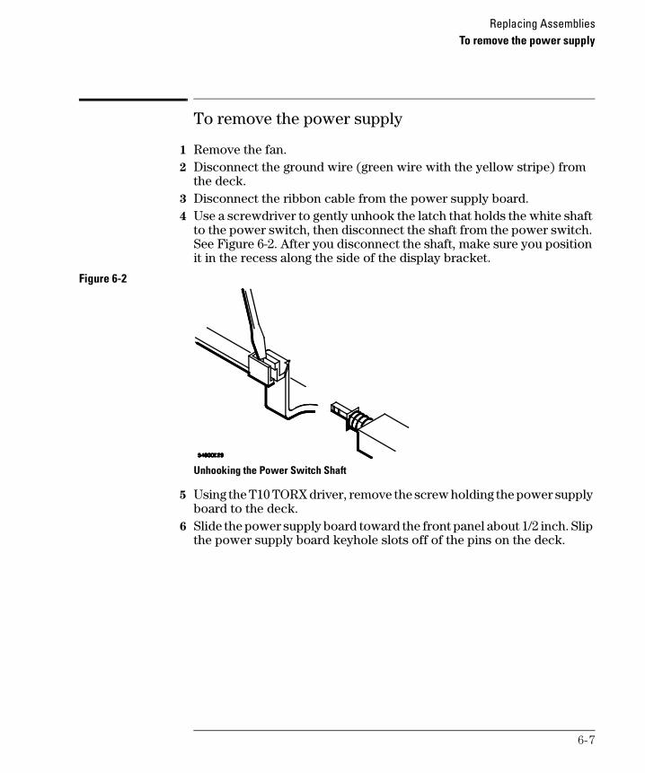
Replacing AssembliesTo remove the power supply
service.book Page 7 Tuesday, February 13, 2001 2:59 PM
To remove the power supply
1 Remove the fan. 2 Disconnect the ground wire (green wire with the yellow stripe) from
the deck. 3 Disconnect the ribbon cable from the power supply board. 4 Use a screwdriver to gently unhook the latch that holds the white shaft
to the power switch, then disconnect the shaft from the power switch. See Figure 6-2. After you disconnect the shaft, make sure you position it in the recess along the side of the display bracket.
Figure 6-2
Unhooking the Power Switch Shaft
5 Using the T10 TORX driver, remove the screw holding the power supply board to the deck.
6 Slide the power supply board toward the front panel about 1/2 inch. Slip the power supply board keyhole slots off of the pins on the deck.
6-7

Replacing AssembliesTo remove the keyboard
service.book Page 8 Tuesday, February 13, 2001 2:59 PM
To remove the keyboard
1 Remove the front panel. 2 Remove all of the knobs by pulling them straight out. 3 Flex the bezel of the front panel to unsnap the small keyboard under
the display opening. 4 Using the T10 TORX driver, remove the four screws from the large
keyboard.
C A U T I O N USE CORRECT SCREWS TO AVOID DAMAGING FRONT PANEL
LABEL!
When you re-install the keyboard, you must re-insert the screws you removed in this step. If you re-insert screws that are longer, they can damage the front panel label.
5 Press down on the top of the keyboard, and rotate the bottom of the keyboard out.
To remove the handle
• Rotate the handle downward until it just passes the last detente position; this is about 1/2 inch before the handle touches the bottom of the oscilloscope.
• Pull the sides of the handle out of the cabinet.
6-8

service.book Page 1 Tuesday, February 13, 2001 2:59 PM
7
Replaceable Parts

service.book Page 2 Tuesday, February 13, 2001 2:59 PM
Replaceable Parts
This chapter describes how to order replaceable assemblies and parts for the Agilent 54621A/22A/24A Oscilloscope and Agilent 54621D/22D Mixed-Signal Oscilloscope.
Diagrams and parts lists are included for assemblies and hardware that you can order.
Before working on the oscilloscope, read the safety summary at the back of this book.
7-2
Replaceable PartsTo order a replacement part
service.book Page 3 Tuesday, February 13, 2001 2:59 PM
To order a replacement part
• To order a part in the material list, quote the Agilent Technologies part number, indicate the quantity desired, and address the order to your nearest Agilent Technologies Sales Office.
• To order a part not listed in the material list, include the model number and serial number of the oscilloscope, a description of the part (including its function), and the number of parts required. Address the order to your nearest Agilent Technologies Sales Office.
• To order using the direct mail order system, contact your nearest Agilent Technologies Sales Office.Within the USA, Agilent Technologies can supply parts through a direct mail order system. The advantages to the system are direct ordering and shipment from the Agilent Technologies Parts Center in Roseville, California. There is no maximum or minimum on any mail order. (There is a minimum amount for parts ordered through a local Agilent Technologies Sales Office when the orders require billing and invoicing.) Transportation costs are prepaid (there is a small handling charge for each order) and there are no invoices.
For Agilent Technologies to provide these advantages, a check or money order must accompany each order. Mail-order forms and specific ordering information are available through your local Agilent Technologies Sales Office. Addresses and telephone numbers are located in a separate document shipped with the instrument.
7-3

Replaceable PartsTo order a replacement part
service.book Page 4 Tuesday, February 13, 2001 2:59 PM
Figure 7-1
Exploded View of the 54621A/22A/24A/21D/22D Oscilloscope
7-4

Replaceable PartsTo order a replacement part
service.book Page 5 Tuesday, February 13, 2001 2:59 PM
Table 7-1
Replaceable Parts
Reference Designator Agilent Part Number
Qty Description
A1 0950-3698 1 Power supply assembly A2 2090-0384 1 Display assembly
A3 54621-66501 1 System board (54621A)A3 54622-66501 1 System board (54622A)A3 54624-66501 1 System board (54624A)A3 54621-66506 1 System board (54621D)A3 54622-66506 1 System board (54622D)
A4 54622-66502 1 Keyboard (54621A, 54622A)A4 54622-66503 1 Keyboard (54621D, 54622D)A4 54624-66504 1 Keyboard (54624A)
A5 0950-2782 1 Floppy disk drive
B1 3160-1006 1 Fan
H1 0515-0390 5 SCR – Machine screw, M4 X 0.7, 6mmH2 0515-0372 9 SCR – Machine screwH3 0515-0380 5 Machine screw M4 X 0.7 X 10 H4 0515-0667 See Descr SCR, Machine screw M3 X 0.5, 25mm LG
(54621A/22A/21D/22D – 1 ea)(54624A – 2 ea)
H5 0515-0658 2 MSPH – Machine screw, M2 6 SMS6H6 0515-2691 2 Screw
MP3 54622-41901 1 Large keypad (54621A/22A)MP3 54622-41903 1 Large keypad (54621D/22D)MP3 54624-41901 1 Large keypad (54624A)
MP4 54621-94301 1 Front-panel label (54621A)MP4 54622-94301 1 Front-panel label (54622A)MP4 54621-94302 1 Front-panel label (54621D)MP4 54622-94302 1 Front-panel label (54622D)MP4 54624-94301 1 Front-panel label (54624A)
MP5 54622-00101 1 Deck
7-5

Replaceable PartsTo order a replacement part
service.book Page 6 Tuesday, February 13, 2001 2:59 PM
MP6 54622-09104 See Descr RFI Gasket (Front)(54621D/22D – 1 ea)(54621A/22A/24A – 2 ea)
MP7 54622-41902 1 Small rubber keypad
MP8 54622-42201 1 Front panel (54621A/22A/24A)MP8 54622-42202 1 Front panel (54621D/22D)
MP9 54622-43701 1 Power switch shaft MP10 54622-64401 1 Cabinet (comes with handle and feet installed) MP11 54622-44901 1 Handle
MP12 54801-47401 See Descr Small knob (54621A/22A – 5 ea)(54621D – 6 ea)(54622D – 7 ea)(54624A – 7 ea)
MP13 54801-47402 See Descr Large knob (54621A/22A – 3 ea)(54621D – 4 ea)(54622D – 3 ea)(54624A – 5 ea)
MP14 54622-43702 1 Intensity shaft
MP15 54622-94304 1 Rear-panel Ext Trig label (54621A/22A)MP15 54624-94302 1 Rear-panel Ext Trig label (54621D/22D/24A)
54622-94303 Label - Power spec54622-94311 Label - CE
MP16 54630-61601 1 Ribbon cable – display MP17 54630-61602 1 Ribbon cable – power supply MP18 54624-27601 See Descr BNC
(54621D/22D – 2 ea)(54621A/22A – 3 ea)(54624A – 4 ea)
MP19 54622-09105 1 RFI Gasket (Rear) – All oscilloscopes –1 each
MP20 2190-0068 1 Washer – Aux Trig & Trig Out(54621A/22A – 1 ea)(54621D/22D/24A – 2 ea)
MP21 1250-2075 1 Nut – Aux Trig & Trig Out(54621A/22A – 1 ea)(54621D/22D/24A – 2 ea)
MP22 54622-63403 1 Attenuator lid MP23 54801-61625 1 Cable – Flex, Floppy
Reference Designator Agilent Part Number
Qty Description
7-6

Replaceable PartsTo order a replacement part
service.book Page 7 Tuesday, February 13, 2001 2:59 PM
W1 8120-1521 1 Standard power cord W1 8120-1703 Power cord option 900, United Kingdom W1 8120-0696 Power cord option 901, Australia W1 8120-1692 Power cord option 902, Europe W1 8120-0698 Power cord option 904, 250 V, USA/Canada
W1 8120-2296 Power cord option 906, Switzerland W1 8120-2957 Power cord option 912, Denmark W1 8120-4600 Power cord option 917, Africa W1 8120-4754 Power cord option 918, Japan
Power cord option 919, IsraelPower cord option 920, Argentina
Option 101 Accessory pouch and front-panel cover (also orderable as part number 54600-68722)
5041-9482 Pouch 54601-44101 Front-panel cover
Probes 10074C 2 X1 passive probe
Input Cable (54621D/22D only)54620-61801 1 Cable, Woven (includes probe leads)
5959-9333 Package replacement probe leads (quantity 5) 5959-9334 Package replacement probe grounds (quantity 5) 5959-9335 Package replacement pod grounds (quantity 5) 5090-4356 Package replacement grabbers (quantity 20, includes 1
5959-9334) 01650-94309 Package of probe labels
Reference Designator Agilent Part Number
Qty Description
7-7

service.book Page 8 Tuesday, February 13, 2001 2:59 PM
7-8

service.book Page ix Tuesday, February 13, 2001 2:59 PM
DECLARATION OF CONFORMITYAccording to ISO/IEC Guide 22 and CEN/CENELEC EN 45014
Manufacturer’s Name:Manufacturer’s Address:
Agilent Technologies, Inc. / Digital Design PGU1900 Garden of the Gods RoadColorado Springs, Colorado80907 U.S.A.
Declares, that the product
Product Name: Digitizing Oscilloscope
Model Number(s): 54621A/D, 54622A/D, and 54624A
Product Option(s): All options based on the above
Is in conformity with:
EMC: IEC 61326-1:1997+A1:1998 / EN 61326-1:1997+A1:1998CCISPR 11:1990/EN 55011:1991– Group 1 Class A[1] IEC 61000-4-2:1995+A1:1998 / EN 61000-4-2:1995 (ESD 4kV CD, 8kV AD)IEC 61000-4-3:1995/EN 61000-4-3:1995 (3V/m 80% AM)IEC 61000-4-4:1995/EN 61000-4-4:1995 (0.5kV line-line, 1kV line-earth)IEC 61000-4-6:1996/EN 61000-4-6:1996 (3V 80% AM, power line)Australia/New Zealand: AS/NZS 2064.1
Saftey IEC 61010-1:1990+A1:1992+A2:1995 / EN 61010-1:1994+A2:1995Canada: CSA C22.2 No. 1010.1:1992USA: UL 3111-1:1994
Additional Information:
The product herewith complies with the requirements of the Low Voltage Directive 73/23/EEC and the EMC Directive 89/336/EEC (including 93/68/EEC) and carries the CE-marking accordingly (European Union).
[1] The product was tested in a typical configuration with Agilent Technologies test systems.
Date: 01/27/2000Name
Ken Wyatt / Product Regulations Manager
For further information, please contact your local Agilent Technologies sales office, agent or distributor.

service.book Page x Tuesday, February 13, 2001 2:59 PM
service.book Page 1 Tuesday, February 13, 2001 2:59 PM
© Copyright Agilent Technologies 2000,2001All Rights Reserved.
Reproduction, adaptation, or translation without prior written permission is prohibited, except as allowed under the copyright laws.
Restricted Rights Legend.
Use, duplication or disclosure by the U.S. Government is subject to restrictions as set forth in subparagraph (c) (1) (ii) of the Rights in Technical Data and Computer Software clause at DFARS 252.227-7013 for DOD agencies, and subparagraphs (c) (1) and (c) (2) of the Commercial Computer Software Restricted Rights clause at FAR 52.227-19 for other agencies.Agilent Technologies 3000 Hanover Street Palo Alto, California 94304 U.S.A.
Document Warranty
The information contained in this document is subject to change without notice.
Agilent Technologies
makes no warranty of any
kind with regard to this
material, including, but
not limited to, the implied
warranties of
merchantability or fitness
for a particular purpose.
Agilent Technologies shall not be liable for errors contained herein or for damages in connection with the furnishing, performance, or use of this material.
Safety
This apparatus has been designed and tested in accordance with IEC Publication 1010, Safety Requirements for Measuring Apparatus, and has been supplied in a safe condition. This is a Safety Class I instrument (provided with terminal for protective earthing). Before applying power, verify that the correct safety precautions are taken (see the following warnings). In addition, note the external markings on the instrument that are described under "Safety Symbols."
Warning
Before turning on the instrument, you must connect the protective earth terminal of the instrument to the protective conductor of the (mains) power cord. The mains plug shall only be inserted in a socket outlet provided with a protective earth contact. You must not negate the protective action by using an extension cord (power cable) without a protective conductor (grounding). Grounding one conductor of a two-conductor outlet is not sufficient protection.• Only fuses with the required rated current, voltage, and specified type (normal blow, time delay, etc.) should be used. Do not use repaired fuses or short-circuited fuseholders. To do so could cause a shock of fire hazard.
• Service instructions are for trained service personnel. To avoid dangerous electric shock, do not perform any service unless qualified to do so. Do not attempt internal service or adjustment unless another person, capable of rendering first aid and resuscitation, is present.• If you energize this instrument by an auto transformer (for voltage reduction), make sure the common terminal is connected to the earth terminal of the power source.• Whenever it is likely that the ground protection is impaired, you must make the instrument inoperative and secure it against any unintended operation.• Do not operate the instrument in the presence of flammable gasses or fumes. Operation of any electrical instrument in such an environment constitutes a definite safety hazard.• Do not install substitute parts or perform any unauthorized modification to the instrument.• Capacitors inside the instrument may retain a charge even if the instrument is disconnected from its source of supply.• Use caution when exposing or handling the CRT. Handling or replacing the CRT shall be done only by qualified maintenance personnel.
Safety Symbols
Instruction manual symbol: the product is marked with this symbol when it is necessary for you to refer to the instruction manual in order to protect against damage to the product.
Hazardous voltage symbol.
Earth terminal symbol: Used to indicate a circuit common connected to grounded chassis.
W A R N I N G
The Warning sign denotes a hazard. It calls attention to a procedure, practice, or the like, which, if not correctly performed or adhered to, could result in personal injury. Do not proceed beyond a Warning sign until the indicated conditions are fully understood and met.
C A U T I O N
The Caution sign denotes a hazard. It calls attention to an operating procedure, practice, or the like, which, if not correctly performed or adhered to, could result in damage to or destruction of part or all of the product. Do not proceed beyond a Caution symbol until the indicated conditions are fully understood or met.
Agilent TechnologiesP.O. Box 21971900 Garden of the Gods RoadColorado Springs, CO 80901

service.book Page 2 Tuesday, February 13, 2001 2:59 PM
Product Warranty
This Agilent Technologies product has a warranty against defects in material and workmanship for a period of three years from date of shipment. During the warranty period, Agilent Technologies will, at its option, either repair or replace products that prove to be defective. For warranty service or repair, this product must be returned to a service facility designated by Agilent Technologies. For products returned to Agilent Technologies for warranty service, the Buyer shall prepay shipping charges to Agilent Technologies and Agilent Technologies shall pay shipping charges to return the product to the Buyer. However, the Buyer shall pay all shipping charges, duties, and taxes for products returned to Agilent Technologies from another country. Agilent Technologies warrants that its software and firmware designated by Agilent Technologies for use with an instrument will execute its programming instructions when properly installed on that instrument. Agilent Technologies does not warrant that the operation of the instrument software, or firmware will be uninterrupted or error free.
Limitation of Warranty
The foregoing warranty shall not apply to defects resulting from improper or inadequate maintenance by the Buyer, Buyer- supplied software or interfacing, unauthorized modification or misuse, operation outside of the environmental specifications for the product, or improper site preparation or maintenance.
No other warranty is
expressed or implied.
Agilent Technologies
specifically disclaims the
implied warranties of
merchantability or fitness
for a particular purpose.
Exclusive Remedies
The remedies provided herein are the buyer’s sole and exclusive remedies. Agilent Technologies shall not be liable for any direct, indirect, special, incidental, or consequential damages, whether based on contract, tort, or any other legal theory.
Assistance
Product maintenance agreements and other customer assistance agreements are available for Agilent Technologies products. For any assistance, contact your nearest Agilent Technologies Sales Office.
Certification
Agilent Technologies certifies that this product met its published specifications at the time of shipment from the factory. Agilent Technologies further certifies that its calibration measurements are traceable to the United States National Institute of Standards and Technology, to the extent allowed by the Institute’s calibration facility, and to the calibration facilities of other International Standards Organization members.
About this edition
This is the Agilent 54621A/
22A/24A Oscillosocpes and
Agilent 54621D/22D Mixed-
Signal Oscilloscopes Service
Guide.
Publication number 54622-97025, February 2001
Print history is as follows:54622-97025, February 200154622-97000, March 2000Printed in USA.
New editions are complete revisions of the manual. Many product updates do not require manual changes; and, conversely, manual corrections may be done without accompanying product changes. Therefore, do not expect a one-to-one correspondence between product updates and manual updates.