agency of natural resources …dec.vermont.gov/sites/dec/files/dwgwp/dwrules/pdf/vtwsr2010.pdfagency...
TRANSCRIPT

AGENCY OF NATURAL RESOURCES DEPARTMENT OF ENVIRONMENTAL CONSERVATION
Water Supply Division
The Old Pantry 103 South Main Street
Waterbury, Vermont 05671-0403 (802) 241-3400
(800) 823-6500 Toll-free in Vermont FAX (802) 241-3284
www.VermontDrinkingWater.org
ENVIRONMENTAL PROTECTION RULES CHAPTER 21
WATER SUPPLY RULE
Original Effective Date: September 24, 1992 REVISION DATE: December 1, 2010
NOTE: The complete rule consists of the following parts:
Subchapters 1 - 16 Appendix A, Parts 1 - 10 - General Standards Appendix A, Part 11 - Non-Community and Non-Public Water Systems Appendix A, Part 12 - Construction & Isolation Standards for Wells Appendix B - Long Range Plan Requirements Appendix C - Bacteriological Monitoring Requirements Appendix D - Operation & Maintenance Manual Standards
Most people will not need all parts of the Rule. If you need a part that you do not have, please call the Water Supply Division at (800) 823-6500 or (802) 241-3400 and request the part(s) you need. The Water Supply Division will also provide a free copy of the most recent version of the federal regulations referenced in the rule, 40 CFR Parts 141-143. These are also available on the division’s website at http://www.anr.state.vt.us/dec/watersup/wsrules.htm.


Vermont Water Supply Rule December 1, 2010
Page 1
TABLE OF CONTENTS INTRODUCTION .......................................................................................................................... 7 Subchapter 21-1 AUTHORITY AND PURPOSE ....................................................................... 11
1.1 Authority ...................................................................................................................... 11 1.2 Purpose......................................................................................................................... 11
Subchapter 21-2 DEFINITIONS AND ABBREVIATIONS ...................................................... 12 2.1 General ......................................................................................................................... 12 2.2 Definitions .................................................................................................................... 12 2.3 Abbreviations .............................................................................................................. 17
Subchapter 21-3 PERMITS - ADMINISTRATION ................................................................... 20 3.0 Prohibitions ................................................................................................................. 20 3.1 Permits ......................................................................................................................... 20 3.2 Suspension or revocation of permit ........................................................................... 21 3.3 (Reserved) ................................................................................................................... 21 3.4 Appeals ......................................................................................................................... 21 3.5 Transfer or Assignment of Permits ........................................................................... 21 3.6 Requirements of Other Statutes and Permitting Authorities ................................. 21 3.7 Variances from Technical Standards ........................................................................ 22 3.8 Petition for Declaratory Ruling ................................................................................. 23 3.9 Compliance with Permits ........................................................................................... 23
Subchapter 21-4 SOURCE and CONSTRUCTION PERMITS ................................................... 24 4.0 General ......................................................................................................................... 24
4.1 Source Permits ........................................................................................................ 25 4.1.1.1 Step 1. Source Permit Application ................................................................... 26 4.1.1.2 Step 2. Site Inspection ......................................................................................... 26 4.1.1.3 Step 3. Source Application Public Notice and ................................................. 26 4.1.1.4 Step 4. Source Testing Application/Source Testing ......................................... 27 4.1.1.5 Step 5. Source Evaluation Report .................................................................... 27 4.1.1.6 Step 6. Source Protection Area Public Notice and Hearing .............................. 28 4.1.1.7 Issuance of Source Permit ................................................................................. 28
4.2 Construction Permits .................................................................................................. 29 Subchapter 21-5 OPERATING PERMITS ................................................................................... 32
5.1 Prohibitions ................................................................................................................. 32 5.2 Posting of Permit ......................................................................................................... 32 5.3 Operating Permits ....................................................................................................... 32 5.4 Temporary Operating Permits .................................................................................. 33 5.5 Conditions .................................................................................................................... 33
Subchapter 21-6 DRINKING WATER QUALITY REQUIREMENTS ..................................... 35 6.1 General Requirements ................................................................................................ 35 6.2 Filtration and Disinfection of Surface Waters and Groundwater Under the Direct Influence of Surface Waters ................................................................................................... 36 6.3 Enhanced Filtration and Disinfection ....................................................................... 37 6.4 Disinfectant and Disinfection Byproduct Monitoring Requirements and Treatment Requirements for Control of Disinfection Byproduct Precursors. ................. 37 6.5 Lead and Copper......................................................................................................... 38

Vermont Water Supply Rule December 1, 2010
Page 2
6.6 Bacteriological Monitoring Requirements ............................................................... 38 6.7 Turbidity Monitoring Requirements ........................................................................ 38 6.8 Inorganic Chemical Monitoring Requirements ....................................................... 38 6.9 Organic Monitoring Requirements ........................................................................... 39 6.10 Radionuclide Monitoring Requirements .................................................................. 39 6.11 (Reserved) .................................................................................................................... 39 6.12 Maximum Contaminant Levels ................................................................................. 39 6.13 Secondary Standards .................................................................................................. 45 6.14 Maximum Contaminant Level Goals (MCLGs) ...................................................... 47 6.16 Health Advisories ........................................................................................................ 47 6.17 Treatment Techniques ................................................................................................ 47
Subchapter 21-7 FACILITY AND OPERATION REQUIREMENTS ....................................... 48 7.1 Operation & Maintenance ......................................................................................... 48 7.2 Disinfection .................................................................................................................. 48 7.3 Fluoridation ................................................................................................................. 49 7.4 Corrosion Control ....................................................................................................... 49 7.5 Sanitary Surveys ......................................................................................................... 50 7.6 Source Protection ........................................................................................................ 50 7.7 Adequate Water Supply Required ............................................................................ 50 7.8 OSHA and VOSHA Compliance ............................................................................... 51
Subchapter 21-8 CROSS CONNECTION CONTROL ............................................................... 52 8.1 Cross Connections ....................................................................................................... 52
Subchapter 21-9 REPORTING REQUIREMENTS AND RECORD KEEPING ....................... 53 9.1 Reporting ..................................................................................................................... 53 9.2 Record Keeping ........................................................................................................... 54
Subchapter 21-10 PUBLIC NOTIFICATION ............................................................................ 55 10.1 General Notification Requirements........................................................................... 55
Subchapter 21-11 BOTTLED & BULK WATER ....................................................................... 58 11.1 Bottled Water .............................................................................................................. 58 11.2 Bulk Water .................................................................................................................. 61
Subchapter 21-12 WATER SYSTEM CLASSIFICATION AND OPERATOR CERTIFICATION ........................................................................................................................ 62
12.1 General ......................................................................................................................... 62 12.2 Responsibilities and Duties......................................................................................... 62 12.3 Operator Certification ................................................................................................ 64 12.4 Revocation or Suspension of Operator Certification .............................................. 65 12.6 Operator in Training (OIT) ....................................................................................... 65 12.7 Provisional Certification ............................................................................................ 65 12.8 Classification of Public Water Systems and Drinking Water Facilities ................ 66 12.9 Experience and Education ......................................................................................... 68 12.10 Certification Renewal ............................................................................................. 69 12.11 Continuing Education ............................................................................................. 70
Subchapter 21-13 LABORATORY CERTIFICATION .............................................................. 71 13.1 Certification ................................................................................................................. 71
Subchapter 21-14 (RESERVED) .................................................................................................. 72 Subchapter 21-15 CAPACITY ................................................................................................... 73

Vermont Water Supply Rule December 1, 2010
Page 3
15.1 General Requirements ................................................................................................ 73 15.2 Technical Capacity...................................................................................................... 73 15.3 Managerial Capacity .................................................................................................. 73 15.4 Financial Capacity ...................................................................................................... 73
Subchapter 21-16 SOURCE WATER PROTECTION ............................................................ 75 16.1 General ......................................................................................................................... 75 16.2 Components of a Source Protection Plan ................................................................. 75 16.3 Updates of Source Protection Plans .......................................................................... 77 16.4 Financial Assistance .................................................................................................... 78
APPENDIX A - VERMONT STANDARDS FOR WATER SYSTEM DESIGN, CONSTRUCTION, AND PROTECTION ..................................................................................... 1
Part 1 SUBMISSION OF PLANS ............................................................................................. 2 1.0 General ....................................................................................................................... 2 1.1 Permit Application .................................................................................................... 2 1.2 Engineer's Report ..................................................................................................... 2 1.3 Plans For Construction............................................................................................. 5 1.4 Design Specifications ................................................................................................ 7 1.5 Revisions To Approved Plans .................................................................................. 7 1.6 Additional Information Required ........................................................................... 7
Part 2 GENERAL DESIGN CONSIDERATIONS ................................................................... 9 2.0 General ....................................................................................................................... 9 2.1 Design Basis ............................................................................................................... 9 2.2 Water Demand .......................................................................................................... 9 2.3 Plant Layout ............................................................................................................ 14 2.4 Building Layout ....................................................................................................... 14 2.5 (Reserved) ................................................................................................................ 14 2.6 Electrical Controls .................................................................................................. 14 2.7 Standby Power ........................................................................................................ 14 2.8 Shop Space and Storage ......................................................................................... 14 2.9 Laboratory Equipment ........................................................................................... 15 2.10 Monitoring Equipment ........................................................................................... 15 2.11 Sample Taps ............................................................................................................ 15 2.12 Facility Water Supply ............................................................................................. 16 2.13 Wall Castings ........................................................................................................... 16 2.14 Meters ....................................................................................................................... 16 2.15 Piping Color Code ................................................................................................... 16 2.16 Disinfection Prior To Use ....................................................................................... 17 2.17 Manuals and Parts Lists ......................................................................................... 17 2.18 Operator Instruction .............................................................................................. 17 2.19 Other Considerations.............................................................................................. 18
Part 3 WATER SUPPLY SOURCE DEVELOPMENT AND PROTECTION ...................... 19 3.0 General ..................................................................................................................... 19 3.1 Reserved ................................................................................................................... 19 3.2 Surface Water Development .................................................................................. 19 3.3 Groundwater Source Development ....................................................................... 21 3.4 Groundwater Under the Direct Influence of Surface Water (GWUDI) ........... 33

Vermont Water Supply Rule December 1, 2010
Page 4
3.5 Standards for Public Non-Community Water Supply Sources .......................... 34 Part 4 WATER SUPPLY TREATMENT .................................................................................... 35
4.0 General ..................................................................................................................... 35 4.1 Clarification ............................................................................................................. 35 4.2 Filtration .................................................................................................................. 38 4.3 Disinfection .............................................................................................................. 49 4.4 Softening .................................................................................................................. 60 4.5 Iron & Manganese Control .................................................................................... 64 4.6 Fluoridation ............................................................................................................. 66 4.8 Taste & Odor Control ............................................................................................ 68 4.9 Microscreening ........................................................................................................ 69 4.10 Waste Handling & Disposal ................................................................................... 70
Part 5 CHEMICAL APPLICATION ....................................................................................... 72 5.0 General ..................................................................................................................... 72 5.1 Facility Design ......................................................................................................... 73 5.2 Chemicals ................................................................................................................. 77 5.3 Operator Safety ....................................................................................................... 77 5.4 Specific Chemicals .................................................................................................. 78
Part 6 PUMPING FACILITIES ............................................................................................... 80 6.0 General ..................................................................................................................... 80 6.1 Location ................................................................................................................... 80 6.2 Pumping Stations .................................................................................................... 80 6.3 Pumps ....................................................................................................................... 82 6.4 Booster Pumps (Main Line) ................................................................................... 83 6.5 Automatic & Remote Controlled Stations ............................................................ 83 6.6 Appurtenances......................................................................................................... 83
Part 7 FINISHED WATER STORAGE .................................................................................. 86 7.0 General ..................................................................................................................... 86 7.1 Plant Storage ........................................................................................................... 90 7.2 Hydropneumatic Tanks .......................................................................................... 91 7.3 Distribution Storage................................................................................................ 92
Part 8 DISTRIBUTION SYSTEMS ........................................................................................ 94 8.0 Materials .................................................................................................................. 94 8.1 Water Main Design ................................................................................................. 94 8.2 Valves ....................................................................................................................... 95 8.3 Hydrants .................................................................................................................. 95 8.4 Air Relief Valves: Valve, Meter & Blow-Off Chambers ..................................... 96 8.5 Installation of Mains ............................................................................................... 96 8.6 Separation of Water Mains, Sanitary Sewers, Storm Sewers & Other Sources of Contamination ................................................................................................................ 97 8.7 Surface Water Crossings ........................................................................................ 99 8.8 Cross-Connections & Interconnections ................................................................ 99 8.9 Water Services & Plumbing ................................................................................. 100 8.10 Service Meters ....................................................................................................... 100 8.11 Water Loading Stations ........................................................................................ 100
Part 9 (RESERVED) .............................................................................................................. 101

Vermont Water Supply Rule December 1, 2010
Page 5
Part 10 (RESERVED) ............................................................................................................. 101 Part 11 NON-COMMUNITY AND NON-PUBLIC WATER SYSTEMS ............................ 102
11.1 Introduction and Definitions ................................................................................ 102 11.2 Preconstruction Requirements ............................................................................ 104
11.2.0 General ............................................................................................................ 104 11.2.1 Basis of Design ............................................................................................... 104 11.2.2 Water Source Site Plan ................................................................................... 105 11.2.3 Design Plans and Specifications ..................................................................... 105 11.2.4 Source Development and Testing ................................................................... 105
11.3 Water System Demand ......................................................................................... 106 11.3.0 Average Day Demand ..................................................................................... 106 11.3.1 Maximum Day Demand .................................................................................. 106 11.3.2 Instantaneous Peak Demand ........................................................................... 106
11.4 Isolation and Separation Distances ..................................................................... 106 11.4.0 General ............................................................................................................ 106
11.5 Well and Spring Construction Standards .......................................................... 112 11.5.0 Water Well ...................................................................................................... 112 11.5.1 Spring and Shallow Well Construction ........................................................... 112
11.6 Water Quantity Testing ........................................................................................ 113 11.6.0 Water Sources ................................................................................................. 113 11.6.1 Long Term Yield Testing ................................................................................ 113 11.6.2 Long Term Yield Analysis .............................................................................. 114 11.6.3 Interference Testing and Analysis .................................................................. 115
11.7 Water Quality ........................................................................................................ 116 11.7.0Water Quality Requirements for Small Scale Water Systems Requiring Permits.116
11.8 Design Standards for Pumping, Storage and Distribution ............................... 118 11.8.0 General Considerations ................................................................................... 118 11.8.1 Pumping Facilities .......................................................................................... 119 11.8.2 Finished Water Storage ................................................................................... 122 11.8.3 Distribution Systems ....................................................................................... 128
Part 12 CONSTRUCTION AND ISOLATION STANDARDS FOR WELLS .................... 134 12.1 General ................................................................................................................... 134 12.2 Isolation Standards for Wells Not Requiring Permits....................................... 134
12.2.1 Well Siting ...................................................................................................... 134 12.3 Construction Standards for Wells Not Requiring Permits and for Public Non-Transient Non-Community water systems, Public Transient Non-Community water systems, and Non-Public water systems requiring permits .......................................... 136
12.3.1 Drilling - General ............................................................................................ 136 12.3.2 Casing and Liner ............................................................................................. 137 12.3.3 Annular Space ................................................................................................. 138 12.3.4 Grouting .......................................................................................................... 138 12.3.5 Closure of Abandoned Wells .......................................................................... 139 12.3.6 Well Finish ...................................................................................................... 139 12.3.7 Pump Installation for Water Wells ................................................................. 140 12.3.8 Flowing Wells ................................................................................................. 141 12.3.9 Well Tag Identification ................................................................................... 141

Vermont Water Supply Rule December 1, 2010
Page 6
12.3.10 Inspection of Wells ......................................................................................... 141 12.4 Construction and Isolation Standards for Wells Requiring Permits ............... 142
12.4.1 Purpose and Scope .......................................................................................... 142 12.4.2 Wells Serving Small Scale Water Systems ..................................................... 142 12.4.3 Construction Standards For Small Scale Water Systems ............................... 142 12.4.4 Isolation Distances .......................................................................................... 143 12.4.5 (Reserved) ....................................................................................................... 143 12.4.6 Wells Requiring Source Permits under the Water Supply Rule ..................... 143 12.4.7 Construction Standards from the Water Supply Rule ..................................... 143 12.4.8 Minimum Protected Depths ............................................................................ 143 12.4.9 Temporary Steel Casing .................................................................................. 144 12.4.10 Permanent Steel Casing Pipe .......................................................................... 144 12.4.11 Nonferrous Casing Materials .......................................................................... 145 12.4.12 Packers ............................................................................................................ 145 12.4.13 Screens ............................................................................................................ 145 12.4.14 Grouting Requirements ................................................................................... 145 12.4.15 Well Construction ........................................................................................... 147 12.4.16 Development ................................................................................................... 147 12.4.17 Capping Requirements .................................................................................... 148 12.4.18 Closure of Abandoned Wells .......................................................................... 148 12.4.19 Aquifer Types and Construction Methods - Special Conditions .................... 148 12.4.20 Well Pumps, Discharge Piping and Appurtenances ....................................... 149
APPENDIX B - LONG RANGE PLAN REQUIREMENTS ..................................................... 151 APPENDIX C - BACTERIOLOGICAL MONITORING REQUIREMENTS.......................... 153 APPENDIX D - OPERATION AND MAINTENANCE MANUALS ...................................... 154

Vermont Water Supply Rule December 1, 2010
Page 7
INTRODUCTION Applicability of This Rule This rule, known as the Water Supply Rule, applies to all water systems in Vermont, which include Public water systems, bottled water systems, Non-Public water systems, and privately owned water sources. Only portions of this rule apply to each type of water system. The section below, entitled "Types of Water Systems," helps the reader to identify his or her type of water system. There may also be other jurisdictions with regulations affecting water systems. This rule is not intended to, and does not affect, modify or repeal existing orders of the Board of Health. Purpose of This Rule This rule is intended to serve a number of purposes. First, and most important, the rule's primary purpose is to regulate water systems in the state so that they provide clean and safe drinking water to Vermont's citizens. This is true for the smallest, single house source to the state's largest system. The rule also establishes well construction standards (contained in Part 12 of Appendix A) which apply to every constructed well in Vermont regardless of the type of facility it serves. Second, by implementing this rule, Vermont qualifies to retain "primacy" for the Safe Drinking Water Act from the federal US Environmental Protection Agency (EPA). Primacy means that the state will administer the federal regulations that apply to all public water systems in the country, instead of EPA. Without state regulations that are at least as strict as the federal ones, Vermont may not administer the federal regulations. We think having primacy represents an advantage to Vermont's water systems. The federal regulations contain some optional provisions that permit exceptions to the regulations when mitigating factors make it difficult or impossible to follow the regulation. Also, there are situations where interpretations of the federal regulations can be made by states with primacy that provide some benefit to the public water systems. EPA has stated that, in the event that they have to administer their own rules in a state without primacy, they will not have the resources to provide most of these permitted exceptions to the regulations. Third, this document contains all of the state's major regulations concerning water systems in a single document, which, in spite of its size, makes it easier for both the regulators and the regulated community to carry out their respective roles. The Agency will bind the various parts of the rule (discussed below) into smaller packages that make sense for the intended recipient. Types of Water Systems This rule varies in its applicability to the different types of water systems, and the administration of this rule is conducted by two different divisions in the Department of Environmental Conservation. Due to the comprehensive nature of this rule, and for the convenience of the reader, the water systems have been categorized into groups, and the introduction at the beginning of each subchapter in the rule explains which sections apply to which water systems.

Vermont Water Supply Rule December 1, 2010
Page 8
Also, when these categories of water systems are referred to in this rule, they are displayed in bold type. The following figure displays the different categories in graphical format, although the reader is cautioned that there are formal definitions for each type of water system contained in the Rule.
Public and Non-Public All water systems are initially classified as either Public water systems or Non-Public water systems. Classification as a Public water system depends on the number of service connections (15 or more) or people served (25 or more) by the system, as is explained in the definition for Public water systems in Subchapter 21-2. Community and Non-Community Public water systems are further subdivided into Public Community water systems and Public Non-Community water systems. Generally, Public Community water systems are those which serve residents on a year-round basis, while Public Non-Community water systems serve non-residential groups of people (e.g., restaurants, schools). Non-Transient and Transient
All Water Systems
Public Non-public
Community Non-Community
Need Permit
No Permit
Non-transient Transient
Bottled

Vermont Water Supply Rule December 1, 2010
Page 9
Public Non-Community water systems are further subdivided into those systems who serve non-residential users who don't change over time (Public Non-Transient Non-Community water system), such as schools and offices, and those non-residential users who do change over time (Public Transient Non-Community water system), such as restaurants and motels. Bottled water systems are considered to be a special case of Public water systems, and are regulated specifically under Subchapter 21-11. They are not included in the categories addressed here. Non-Public Requiring Permits and Non-Public Not Requiring Permits Non-Public water systems include those requiring permits and those not requiring permits. Examples of Non-Public water systems requiring permits are some 9 lot-or-fewer subdivisions, and public buildings serving fewer than 25 people. Non-public water systems not requiring permits, such as single family homes on lots not subject to state subdivision rules, have no direct responsibilities under the rule, and are regulated indirectly by the standards in Part 12 of Appendix A and the Well Driller Licensing Rule in Chapter 15 of the Environmental Protection Rules. These systems are not included in the categories addressed here, either. The regulations regarding Non-Public water systems have been changing over the past several years and are expected to continue to change. The Regional Office should be contacted regarding what permits and requirements are relevant to these water systems. In summary, then, there are five categories of water systems referred to throughout this rule and grouped for convenience: (a) Public Community water systems; (b) Public Non-Transient Non-Community (NTNC) water systems; (c) Public Transient Non-Community (TNC) water systems; (d) Bottled water systems; and (e) Non-Public water systems requiring permits. The formal definitions for (a) through (d) above (i.e., the Public water systems) are contained in Subchapter 2, Definitions. Public water systems are also subject to regulation under the federal Safe Drinking Water Act. By enacting this rule, the federal regulations will be administered by the Department of Environmental Conservation when it has "primacy," or primary administrative and enforcement authority. The water systems contained in categories (c) and (e) above are generally administered for construction permit purposes, by the Regional Offices of the Wastewater Management Division. The design and construction standards for Public Non-community water systems are contained in Appendix A, Part 11. Continued operating requirements, including operating permits, fees, and other requirements, are administered by the Water Supply Division of the Department of Environmental Conservation. Organization of the Rule The complete Water Supply Rule consists of the sixteen subchapters and four appendices. The chapters are divided into Sections (e.g., 2.12) and Subsections (e.g., 2.18(a)(1)). Each

Vermont Water Supply Rule December 1, 2010
Page 10
subchapter contains a brief introduction which identifies which type(s) of water systems are regulated by that subchapter. These subchapters contain regulatory requirements that water systems must follow. Following the main part of the rule are the four appendices, lettered A through D. Each is briefly described here. Appendix A of the rule contains the Vermont Standards for Water System Design, Construction, and Protection. These are technical standards that apply to persons designing, constructing, and operating water systems. This appendix contains twelve Parts, and the introduction at the beginning of the appendix identifies which parts of the appendix apply to which water systems. The numbering in Appendix A is divided into Parts (e.g., 5) and Subparts (e.g., 5.1.2(a)). Parts 1 through 9 of Appendix A apply to Public Community water systems and Bottled water systems with sources in Vermont. Part 11 contains the technical standards for Public Non-community water systems and Non-public water systems requiring permits, which are considerably simplified from those for Public Community systems. Finally, Part 12 contains standards for water sources, both privately owned (which do not require permits), as well as those for which permits are required from the Water Supply Division or the Wastewater Management Division. Appendix B contains the requirements for the Long Range Plan, a document required under the rules, whose purpose is to assist water systems in proper planning for the continued viability of their systems. Appendix C is a table of the sampling frequencies required for bacteriological monitoring. Appendix D contains the standards for Operation & Maintenance (O&M) Manuals, which are also required under this rule. The Department has made a concerted effort to coordinate this rule with all the appropriate state agencies in order to reduce conflicting or overlapping regulations. For assistance in complying with this rule the reader should contact the nearest Regional Office of the Agency of Natural Resources for Public Non-community water systems or the Water Supply Division in Waterbury for Public Community water systems and bottled drinking water facilities.

Vermont Water Supply Rule December 1, 2010
Page 11
Subchapter 21-1 AUTHORITY AND PURPOSE Introduction This subchapter applies to all water systems. 1.1 Authority This rule is adopted under the authority of 10 V.S.A. Chapter 48, Groundwater Protection; 10 V.S.A. Chapter 56, Public Water Supply; 10 V.S.A. Chapter 61, Water and Waste Water Permits; and 18 V.S.A. §1218. Related statutes include: 3 V.S.A. § 2822 (j), regarding fees; 18 V.S.A. §501b, regarding certification of laboratories; 18 V.S.A. §503, regarding use of laboratory by people; and 24 V.S.A. Chapter 120, regarding funding of public water supply planning and construction. This rule refers to and adopts the authority of the Federal Safe Drinking Water Act: 42 U.S.C. 300 f. et. seq. and except as explicitly provided herein, the rule adopts and incorporates by reference the National Primary Drinking Water Regulations, 40 CFR 141 (July 1, 2009), the National Primary Drinking Water Regulations Implementation, 40 CFR 142(July 1, 2009),and the National Secondary Drinking Water Regulations, 40 CFR 143 (July 1, 2009), under an agreement with the US Environmental Protection Agency, by which the State of Vermont has primary enforcement authority (primacy) in Vermont for the Safe Drinking Water Act. Where necessary to protect the public health, but subject to appeal, the Secretary may require additional drinking water permit conditions under this rule. 1.2 Purpose The purpose of this rule is to protect the public health by assuring safe, affordable drinking water from Public and Non-Public Water systems, and to implement and enforce the provisions of the Federal Safe Drinking Water Act and Vermont statutes. The granting of a permit under this rule does not relieve the water supplier of the responsibility for the satisfactory functioning of the water system, nor limit his/her responsibility or liability under other statutes or rules.

Vermont Water Supply Rule December 1, 2010
Page 12
Subchapter 21-2 DEFINITIONS AND ABBREVIATIONS Introduction This subchapter applies to the following water systems: (a) Public Community water systems; (b) Public Non-Transient Non-Community (NTNC) water systems; (c) Public Transient Non-Community (TNC) water systems; (d) Bottled Water systems; and (e) Non-Public water systems requiring permits. Additional definitions applying only to Non-Community water systems and Non-public water systems requiring permits are contained in Part 11 of Appendix A. Additional definitions are also contained in 40 CFR, Sections 141.2, 142.2, and 143.2 which are adopted herein. These definitions apply to federal regulations which affect Public water systems (see below for definition of Public water systems). 2.1 General The following definitions and abbreviations shall apply in the interpretation and enforcement of this rule. 2.2 Definitions ACTION LEVEL means the concentration of a substance in drinking water which clearly provides adequate public health protection, as determined by the Vermont Department of Health. AGENCY means the Vermont Agency of Natural Resources. BOTTLED WATER means any non-carbonated, non-flavored water placed in a sealed container for sale or distribution to the public with the express or implied intent of providing water for human consumption. BOTTLED WATER SYSTEM means a Public water system which bottles drinking water for public distribution and sale. A Domestic Bottled Water System is a Bottled Water System with at least one source located within Vermont. An Imported Bottled Water System is a Bottled Water System with all sources located outside of Vermont. BULK WATER means drinking water delivered to consumers or water purveyors by means other than pipeline or bottled water. CAPACITY means that a public water system has the technical, financial, and management capabilities to consistently comply with current performance standards, including the requirements of this rule and the Safe Drinking Water Act, 42 U.S.C. Section 300f et. seq., as amended.

Vermont Water Supply Rule December 1, 2010
Page 13
COLOR UNIT means the color produced by 1 mg/l platinum in the form of the chloroplatinate ion. COMMISSIONER means the Commissioner of the Vermont Department of Environmental Conservation or the Commissioner's designee. CONFINING LAYER means a continuous, extensive geologic unit of low permeability. CROSS CONNECTION means any actual or potential connection between the public water supply and a source of contamination or pollution. DEPARTMENT means the Vermont Department of Environmental Conservation. DRINKING WATER means non-carbonated, non-flavored water that is intended for human consumption or other consumer uses whether provided by a Public water system or in a container, bottle or package or in bulk, including water used for production of ice, foodstuffs or other products designed for human consumption. DRINKING WATER FACILITY means a bottled or bulk water facility requiring a permit to operate under this rule. EMERGENCY SOURCE means a water source which is not permitted for use by a Public water system. It is identified only as an alternate water source that may be used for a limited duration emergency in the event of an unforeseen circumstance that prevents the water system’s permitted sources from supplying either adequate quantity or quality of water. GROSS BETA ACTIVITY means the total radioactivity due to beta particle emission as inferred from measurements on a dry sample. GROUNDWATER means water below the land surface in a zone of saturation. HYDROGEOLOGIST means a person with training or experience in bedrock geology, glacial geology, and groundwater hydrology sufficient to prepare adequately the hydrogeologic analyses required by this rule. INFILTRATION GALLERY means a subsurface collection system located so as to intercept ambient groundwater or surface water flow and generally designed with roughly horizontal collection pipes. LABORATORY CERTIFICATION means that a laboratory meets the minimum Vermont Department of Health requirements for specific parameters and that the laboratory is granted approval for analyses of these parameters for a maximum of three (3) years. MAN-MADE BETA PARTICLE AND PHOTON EMITTERS means all radionuclides emitting beta particles and/or photons listed in Maximum Permissible Body Burdens and Maximum

Vermont Water Supply Rule December 1, 2010
Page 14
Permissible Concentration of Radionuclides in Air or Water for Occupational Exposure, NBS Handbook 69, except the daughter products of thorium 232, uranium-235 and uranium-238. MICROSCOPIC PARTICULATE ANALYSIS (MPA) means the analysis described in the US Environmental Protection Agency document, “Consensus Method for determining groundwaters under the direct influence of surface water using microscopic particulate analysis” (EPA document # 910/9-92-029). MONITORING WELL means any well constructed for the purpose of monitoring groundwater quantity or quality. OPERATOR means an individual who accepts responsibility for operational activities that will directly affect the quality and/or quantity of drinking water provided to consumers, and who is certified as such by the State of Vermont. OWNER means the person(s) who owns or has an ownership interest in a Public or Non-public water system. An OWNER may designate an authorized representative who has the authority to act on the owner’s behalf in all matters regarding the Public or Non-Public water system, and is designated to be the contact person in place of the OWNER for all communications from the Secretary regarding the water system. PERMIT means a written document issued by the Secretary (see below) pursuant to these regulations, giving a designated person approval to operate and/or construct, alter or renovate a specific water system or drinking water facility. PERSON means an individual, partnership, fire district, association, cooperative, syndicate, company, firm, trust, corporation, government corporation, municipal corporation, institution, state, federal, or municipal government department, division, bureau, agency, or any other entity recognized by law. POTABLE WATER means water free from impurities in amounts sufficient to cause disease or harmful physiological effects, and having bacteriological, chemical, physical and radiological quality conforming to applicable standards of the Secretary. POTENTIAL SOURCE OF CONTAMINATION means any activity or condition which may adversely affect water quality. PRIMARY DRINKING WATER STANDARD means a standard which: (a) applies to Public and Non-Public water systems and drinking water; (b) applies to contaminants which may have an adverse effect on the health of persons; (c) specifies for each such contaminant either:
(1) a maximum contaminant level (MCL), if, in the judgment of the Secretary, it is economically and technologically feasible to ascertain the level of such contaminants in drinking water and Public and Non-Public water systems, or
(2) if, in the judgment of the Secretary, it is not economically or technologically feasible to ascertain the level of such contaminant, each treatment technique

Vermont Water Supply Rule December 1, 2010
Page 15
known to the Secretary which leads to a reduction of the contaminants identified in Subchapter 21-6; and
(d) contains criteria and procedures to assure a supply of drinking water which dependably complies with such maximum contaminant levels or treatment techniques.
PUBLIC WATER SOURCE means any surface water or groundwater intake used, or permitted to be used, as a source of drinking water for a Public water system. PUBLIC WATER SOURCE PROTECTION AREA means a surface and subsurface area from or through which contaminants are reasonably likely to reach a Public water system source. PUBLIC WATER SYSTEM means any system(s) or combination of systems owned or controlled by a person, that provides drinking water through pipes or other constructed conveyances to the public and that has at least fifteen (15) service connections or serves an average of at least twenty five (25) individuals daily for at least sixty (60) days out of the year. Such term includes all collection, treatment, storage and distribution facilities under the control of the water supplier and used primarily in connection with such system, and any collection or pretreatment storage facilities not under such control which are used primarily in connection with such system. Public water system shall also mean any part of a system which does not provide drinking water, if use of such a part could affect the quality or quantity of the drinking water supplied by the system. Public water system shall also mean a system which bottles drinking water for public distribution and sale (see also Bottled Water System).
(a) PUBLIC COMMUNITY WATER SYSTEM means a Public water system which serves at least fifteen (15) service connections used by year-round residents or regularly serves at least 25 year-round residents.
(b) PUBLIC NON-COMMUNITY WATER SYSTEM means a Public water system that is not a Public Community water system. (1) PUBLIC NON-TRANSIENT NON-COMMUNITY WATER SYSTEM
(NTNCWS) means a Public water system that is not a Public Community water system and that regularly serves at least 25 of the same persons daily for more than six months per year. Examples: schools, factories, office buildings.
(2) PUBLIC TRANSIENT NON-COMMUNITY WATER SYSTEM (TNCWS) means a Public Non-community water system that is not a Non-transient Non-community system. Examples: restaurants, motels, campgrounds.
PUBLIC WATER SYSTEM CLASS means the grouping of Public water systems based on type of treatment technology and type of Public water system. A Class may, where appropriate, also be grouped according to size of population served by the system. PUBLIC WATER TREATMENT PLANT means a facility providing for the treatment of water, or the protection of water by treatment, by any one, or any combination of the controlled processes of coagulation, flocculation, sedimentation, adsorption, filtration, disinfection, or other processes which produce potable water.

Vermont Water Supply Rule December 1, 2010
Page 16
REPEAT COMPLIANCE PERIOD means any subsequent compliance period after the initial compliance period. REGIONAL ADMINISTRATOR means the Regional Administrator of the United States Environmental Protection Agency, Region 1, in Boston, Massachusetts. REGISTERED PROFESSIONAL ENGINEER means an engineer registered with the Vermont Board of Professional Engineering. RESPONSIBLE CHARGE means the operator(s) in responsible charge is defined as the person(s) designated by the owner to be the certified operator(s) who makes decisions regarding the daily operational activities of a public water system, water treatment facility and/or distribution system that will directly affect the quality and/or quantity of drinking water. SECONDARY DRINKING WATER STANDARD means a standard which is not a primary standard, which applies to Public water systems, and specifies the maximum contaminant levels which, in the judgment of the Secretary, are requisite to protect the public welfare. Such standards may apply to any contaminant in drinking water which may:
(a) adversely affect the odor or appearance of such water and consequently may cause a substantial number of persons served by the Public water system providing such water to discontinue its use, or
(b) otherwise adversely affect the public welfare. SECRETARY means the Secretary of the Agency of Natural Resources or the Secretary's designee. SERVICE CONNECTION means each single family home, each living unit within a condominium , single rental unit, mobile home, store, or other commercial, educational, or industrial establishment, or other living unit which obtains water from a water system. SHALL means that the person or system designated must comply with the associated action verb or be subject to enforcement action (see SHOULD). SHOULD means that compliance with the associated action verb is recommended, but not required and that no enforcement action will follow (see SHALL). SOURCE PROTECTION AREA means a PUBLIC WATER SOURCE PROTECTION AREA (see above). SPRING means a groundwater source entirely dependent on gravity to move water from the source to the distribution system. SURFACE WATER (for purposes of determining isolation distance from a groundwater source under Subsection 3.5.8) means any body of surface water including rivers, streams, creeks, brooks, reservoirs, natural or artificial ponds, lakes, swamps and marshes which have discernible edges and in which terrestrial vegetation does not grow.

Vermont Water Supply Rule December 1, 2010
Page 17
TURBIDITY UNIT (TU) means the unit of measurement of particulate matter in a water sample based upon a comparison of the intensity of light scattered by the sample under defined conditions with intensity of light scattered by a standard reference suspension under the same conditions. VERMONT HEALTH ADVISORY LEVEL means the concentration of a substance in drinking water below which the water does not pose a public health risk, or public health hazard as defined in 18 V.S.A. Chapter 1, and for which there is no Maximum Contaminant Level identified in this rule. VIRUS means a virus of fecal origin which is infectious to humans by waterborne transmission. VULNERABLE means a Public water system, or source, which is at risk of contamination by a constituent or constituents because of known conditions in the water system, geologic setting, or land uses in the source protection area. WATER SUPPLIER means any person who owns or operates a Public water system or who provides or sells bottled or bulk drinking water. WATER VENDING MACHINE shall mean a water-connected vending machine designed to dispense drinking water, and to reduce or remove turbidity, off-tastes and odors and to provide disinfection. Processes for dissolved solids reduction or removal may also be used. WELL means any hole drilled, driven, bored, excavated, or created by similar method into the earth to locate, monitor, extract, or recharge groundwater where the water table or potentiometric surface is artificially lowered through pumping. 2.3 Abbreviations ANSI means the American National Standards Institute API means the American Petroleum Institute ASME means the American Society of Mechanical Engineers ASSE means the American Society of Sanitary Engineering ASTM means the American Society for Testing Materials AWWA means the American Water Works Association BOCA means the Building Officials and Code Administration CDC means the Center for Disease Control CEUs means Continuing Education Units

Vermont Water Supply Rule December 1, 2010
Page 18
CFR means Code of Federal Regulations CT means "Concentration X Time" (see definition in 40 C.F.R. Subpart A) DPD means N,N-diethyl-p-phenylenediamine or ferrous titrimetric EPA means the Environmental Protection Agency, of the United States GAC means Granular Activated Carbon GMPRs means Good Manufacturing Practice Regulations HAV means Hepatitis A Virus NIOSH means National Institute for Occupational Safety and Health NSF means the National Sanitary Foundation NTNC means Non-Transient Non-Community MPA means Microscopic Particulate Analysis MCL means Maximum Contaminant Level MCLG means Maximum Contaminant Level Goal mg/l means milligram per liter MRDL means Maximum Residual Disinfection Level NTNCWS means Non-Transient Non-Community Water System O&M means Operation and Maintenance OIT means Operator-In-Training OSHA means the Occupational Safety and Health Administration PE means Professional Engineer ppm means parts per million PSI means pounds per square inch. PSOC means Potential Sources Of Contamination

Vermont Water Supply Rule December 1, 2010
Page 19
PVC means Polyvinyl Chloride ROW means Right Of Way SMCL means Secondary Maximum Contaminant Level SPA means Source Protection Area. SPP means Source Protection Plan TDS means Total Dissolved Solids TNC means Transient Non-Community TNCWS means Transient Non-Community Water System TU means Turbidity Unit ug/l means microgram per liter USC means United State Code USGS means the United States Geological Survey UV means Ultraviolet VOSHA means the Vermont Occupational Safety and Health Administration VDH means the Vermont Department of Health VHA means Vermont Health Advisory VOC means Volatile Organic Chemicals V.S.A. means Vermont Statute Annotated WWMD means Wastewater Management Division, a division of the Department of Environmental Conservation.

Vermont Water Supply Rule December 1, 2010
Page 20
Subchapter 21-3 PERMITS - ADMINISTRATION Introduction Unless otherwise stated below, this subchapter applies to the following water systems: (a) Public Community water systems; (b) Public Non-Transient Non-Community (NTNC) water systems; (c) Public Transient Non-Community (TNC) water systems; (d) Bottled water systems; and (e) Non-Public water systems requiring permits. This subchapter applies to Source Permits, Construction Permits and Operating Permits. Operating Permits consist of Operating Permits and Temporary Operating Permits. This subchapter applies to Source Permits for Public Community, Non-Transient Non-Community, and Domestic Bottled water systems. 3.0 Prohibitions 3.0.1 No person shall modify, construct, or operate a Public water system without first
obtaining the appropriate permit from the Secretary. 3.0.2 No person shall modify or construct a Non-Public water system requiring a permit
without first obtaining a permit from the Secretary. 3.0.3 No person shall modify or construct a new Public Community or Domestic Bottled
water system source, change an existing water source into a Public Community or Domestic Bottled water system source, or operate a Public Community or Domestic Bottled water system source without first obtaining a permit from the Secretary.
3.0.4 No person shall use or connect an unpermitted water source, including an emergency
source, to a Public Water System, except (a) following public notice to the water system customers (according to Agency public
notification requirements); (b) providing notice to the Secretary as soon as possible, but no later than within 12 hours
of its connection or use; and (c) in an emergency situation for a limited duration, no more than 90 cumulative days
without prior written approval of extension by the Secretary. 3.1 Permits 3.1.1 The Secretary may issue, renew, deny, suspend, or revoke a Public water system or
drinking water facility permit.

Vermont Water Supply Rule December 1, 2010
Page 21
For Public Transient Non-Community, and Non-Public water systems, Construction Permits and development of new drinking water sources are administered by the Wastewater Management Division through its Regional Offices. All other drinking water permits are issued through the Water Supply Division, including Construction Permits for treatment at Public Transient Non-Community water systems.
3.1.2 For each application for a new source for a Public Community, Domestic Bottled, or a
Public Non-Transient Non-Community water system, the Secretary shall provide notice and opportunity for hearing or written comment, or both, in accordance with 10 V.S.A., §1675.
3.2 Suspension or revocation of permit 3.2.1 Any permit issued under these regulations may be suspended or revoked if the Secretary
finds that the Public water system or drinking water facility is maintained or operated in violation of this rule or of any law, rule, order, ordinance or regulation applicable thereto, or is in violation of the conditions stated in the permit, or that the water supplier has submitted false or misleading information to the Secretary.
3.2.2 The Secretary shall comply with 10 V.S.A., §1675 and 3 V.S.A. §814 prior to revocation
or suspension of a permit. 3.2.3 When a permit has been denied, suspended or revoked, emergency orders to protect the
users may be issued and remain in effect until the operating permit is validated. 3.3 (Reserved) 3.4 Appeals 3.4.1 Final decisions made by the Secretary regarding permit issuance, renewal, denial,
revocation, and suspension, for Public water systems, may be appealed formally as provided by 10 V.S.A., §1680 (or 10 V.S.A., §1977 for Non-Public water systems).
3.5 Transfer or Assignment of Permits 3.5.1 Operating Permits (see Subchapter 21-5), Source Permits, and Public Community, Non-
Transient Non-Community, Domestic Bottled and Transient Non-Community Water System Construction Permits are not transferable or assignable and shall automatically become invalid upon a change of ownership or upon suspension or revocation. A new owner shall obtain a new permit prior to operation of the water system.
3.6 Requirements of Other Statutes and Permitting Authorities A permit issued under this rule allows specific actions by the permittee. However, it does not relieve the permittee of obligations he or she may have under other statutes, regulations or permitting authorities including but not limited to Act 250, Agency of Natural Resources,

Vermont Water Supply Rule December 1, 2010
Page 22
Department of Public Safety, Department of Agriculture, Food and Markets, Department of Education, Public Service Board, Agency of Human Services, and Department of Public Service. 3.7 Variances from Technical Standards 3.7.1 General A request for approval of alternatives to the requirements of the Vermont Standards for Water System Design, Construction and Protection (Appendix A) shall be filed in writing. The application for a variance shall state the manner in which the proposed system or design varies from the specified criteria of these standards, and a basis for finding that the proposal meets the criteria set forth in Subsection 3.7.2 below. Requests for approval under this section shall be reviewed by the Secretary within 30 days of application. For Public Transient Non-Community, and Non-Public Water System Construction Permits, variances may only be issued under the criterion in Subsection 3.7.2(e), below. The Secretary shall maintain a file available to the public of all decisions issued under this section. 3.7.2 Variances Criteria The Secretary may permit an alternative to the requirements of the standards in Appendix A upon finding that: (a) The proposal is designed to achieve the purpose of the standards as set forth in Section
1.2; (b) The proposed design is based on established engineering and/or hydrogeologic principles
and can be expected to perform at the same level of reliability and health protection as the design criteria and standards included in this rule;
(c) The proposed project will comply with all drinking water quality standards and not create a public health hazard or significant risk;
(d) The public and persons using the water system are protected from health hazards, health risks, pollution and increased costs in the event that the proposed alternative does not meet the purpose of this rule; and
(e) In the case of remediation of existing health hazards, the proposal shall be in compliance, as closely as possible, with Appendix A of this rule, shall not be to accommodate new growth, and shall not violate drinking water quality standards.
3.7.3 Performance Security The Secretary may require bonding or other security of an appropriate amount to ensure performance or replacement of any alternative in the event that it fails to meet the purpose of this rule. Security or bonding shall be established for a specified time period in each case. 3.7.4 Decision and Notice

Vermont Water Supply Rule December 1, 2010
Page 23
The Secretary shall make the decision to allow or deny an alternate proposal in writing and shall state the reasons therefore. A copy of each decision granted or approved under this section shall be posted for at least one month in the offices of the municipalities in which the project is located. Additionally, public notification to the users of the system shall be made in accordance with the provisions of Subchapter 21-10. 3.8 Petition for Declaratory Ruling On petition of a person who may be affected by a statute or rule administered by the Agency, the Secretary shall issue a declaratory ruling as to the applicability of any statutory provision or any rule as provided for in 3 V.S.A. §808. 3.9 Compliance with Permits The Secretary may issue a permit to the applicant subject to the conditions consistent with the purposes of this rule. No person shall proceed with a construction project except in accordance with the terms and conditions of the permit.

Vermont Water Supply Rule December 1, 2010
Page 24
Subchapter 21-4 SOURCE and CONSTRUCTION PERMITS Introduction This subchapter applies to the following water systems: (a) Public Community water systems; (b) Public Non-Transient Non-Community (NTNC) water systems; (c) Public Transient Non-Community (TNC) water systems; (d) Domestic Bottled water systems; and (e) Non-Public water systems requiring permits. 4.0 General Source permits for Public Community and Domestic Bottled water systems shall be governed by Section 4.1 of this subchapter, and the requirements of Appendix A, Part 3. Source permits for Public Non-Transient Non-Community water systems shall be governed by Appendix A Part 11. Construction permits for, or improvements to, Public Community and Bottled water systems shall be governed by Section 4.2 of this subchapter, as well as the requirements of Appendix A, Parts 1 through 10, and 12. Construction permits for Public Non-Transient Non-Community, Public Transient Non-Community, and Non-Public water systems shall be governed by Sections 4.2.4, and 4.2.8 of this subchapter and the requirements of Appendix A, Parts 11 and 12. For Public Non-Transient Non-Community and Public Transient Non-Community water systems, some provisions of Parts 1-10 apply and are clearly noted in the text of Part 11 of Appendix A. 4.0.1 Prohibitions No person shall begin construction of, alter, renovate, or convert for use as a Public or a Non-Public water system requiring a permit, any system or any portion thereof, except as provided in Section 4.0.2 of this subchapter, without first receiving a Source Permit or Construction Permit from the Secretary. 4.0.2 Exemptions from Source and Construction Permits No Construction Permit for Public water systems will be required for minor system improvements such as replacement of hydrants on existing distribution line(s), pipe extension projects of less than 500 feet, minor alterations or maintenance of an existing water system, and no source permit will be required for minor maintenance such as replacement of source pump or source structure repair, which would not in and of itself affect the quality or quantity of water service rendered, providing work is done according to the Vermont Standards for Water System Design, Construction and Protection (see Appendix A of this rule). It is recommended that the water supplier contact the Secretary for consultation on plans for minor improvements.

Vermont Water Supply Rule December 1, 2010
Page 25
4.0.3 Applicability of Vermont Standards In addition to meeting the applicable requirements of this rule, all water system changes including construction, alteration, renovation, installation, extension and/or connection after the date this rule become effective shall conform to the Vermont Standards for Water System Design, Construction and Protection in Appendix A. 4.1 Source Permits 4.1.0.1 Application Requirements (a) Source Permits are required for new Public Community, Public Non-Transient Non-
Community, and Domestic Bottled water system sources and an increase in approved yield of existing Public Community, Public Non-Transient Non-Community, and Bottled water system sources, including but not limited to hydrofracturing and deepening of sources.
(b) General procedural requirements for Public Community and Domestic Bottled water
system Source Permits are outlined in subsection 4.1.1 below. Technical requirements for surface water are outlined in Appendix A, Subpart 3.2 and for groundwater in Appendix A, Subpart 3.3.
(c) General procedural requirements for Public Non-Transient Non-Community water
system Source Permits are outlined in Appendix A Parts 11 and 12. (c) Any permitted Public Community or Domestic Bottled water source which has not
been connected to the water system for a period of time greater than two years, may at the discretion of the Secretary, be required to obtain a valid Source Permit prior to connection of the source.
4.1.0.2 First-In-Time For the purpose of determining first-in-time for rights to water source development or groundwater degradation, and to accommodate compatible land uses, the following shall be recognized as initiating a project: (a) Submittal of a substantially complete application for approval of a drinking water source; (b) Submittal of a substantially complete application for a building permit or sewage disposal
permit for a non-state regulated project; (c) Submittal of a substantially complete application for a State Permit to dispose, discharge,
or use any substance which may affect water quality; (d) Existing land and groundwater uses; or (e) Other state and local planning actions as reviewed on a case by case basis. 4.1.1 Water System Source Permit Process And General Requirements

Vermont Water Supply Rule December 1, 2010
Page 26
The Secretary uses a step-by-step process culminating in the permitting of a Public Community and Domestic Bottled water source. No Source Permit or Construction Permit will be issued until all of the Secretary’s concerns are addressed. Applicants for a Source Permit shall apply for and receive, as appropriate: (a) Source Construction approval; (b) Source Testing approval; and (c) Source Evaluation Report approval. 4.1.1.1 Step 1. Source Permit Application
Application Form The purpose of the Source Permit Application is to record information required to determine whether the site at the proposed location is suitable for source construction. Applications for a Source Permit shall be submitted on forms provided by the Secretary that request information such as maps indicating source locations, nearby land use activities, project plans, and property ownership. 4.1.1.2 Step 2. Site Inspection A site inspection shall be conducted by the Water Supply Division, along with the applicant and/or consultants. 4.1.1.3 Step 3. Source Application Public Notice and Source Construction (a) For site(s) approved by the Secretary, and prior to construction of source, the applicant
shall provide the Secretary with certification that all landowners adjoining the parcel containing the proposed source have been notified of the proposed source. Certification shall be provided prior to receiving source construction approval.
The Secretary shall give public notice for each proposed public water source by publication in a newspaper of general circulation for the area containing the proposed system and by posting a notice in the clerk's office for the municipality containing the proposed source. The Secretary shall provide an opportunity for written comment or a public hearing, or both, on the application before ruling on the application.
(b) The Secretary will review his or her findings and write a review letter requesting more
information, or one of site approval, conditional approval, or denial of approval for the proposed site.
(c) Source Construction approval shall be valid for two years and may be renewed upon
written request by the applicant at the discretion of the Secretary.

Vermont Water Supply Rule December 1, 2010
Page 27
(d) The applicant may then construct the proposed source per the Secretary’s approved plans. 4.1.1.4 Step 4. Source Testing Application/Source Testing The purpose of the source testing application is to provide the applicant and Secretary with a review of the information needed to determine that the testing and data to be collected will address the concerns of the Secretary with respect to source yield, quality, site, interference/allocation, source protection area delineation, ground water under the direct influence of surface water, and the risk from potential sources of contamination. (a) Applications for Source Testing approval shall be submitted on a form provided by the
Secretary. The form will request information regarding the source, such as pump test specifications, data collection, and other water uses in the area.
(b) The Secretary will review a completed application and write a letter of approval,
conditional approval, or denial. (c) Source Testing approval shall be valid for two years and may be renewed upon written
request of the applicant at the discretion of the Secretary. 4.1.1.5 Step 5. Source Evaluation Report Source evaluation reports must be prepared under the supervision of a hydrogeologist or engineer, knowledgeable in the field of well hydraulics and contaminant hydrogeology. Each report must consider and comment on the following: (a) Site isolation zone, ownership and/or easements; (b) Water Quality Results for the primary and secondary contaminants contained in Table 6-
1 and Table 6-2 (Appendix A Subpart 3.2.4 includes information about additional monitoring that may be required);
(c) Water Quantity (See Appendix A, subparts 3.2.3 and 3.3.3); (d) Source construction, as built engineering plans shall be included; (e) Interference with other water supply withdrawals as appropriate; (f) Source Protection Area and Protection Plan (See Subchapter 21-16); (g) Agricultural lands in source protection area; and (h) Additional studies as required by the Secretary. (i) For pumped groundwater sources the report shall include but not be limited to the
following: (1) A summary of the test design, test method, problems encountered, analysis used,
and detailed hydrogeologic setting. Include a drawdown/discharge vs. discharge graph (Sw/Q vs Q) and evaluation of step test data using published methodologies acceptable to the Secretary.
(2) Published analytical method or any preapproved proprietary method proposed by the consultant and approved by the Secretary for safe yield appropriate to the hydrogeologic setting based on data collected from the constant discharge and recovery tests. Rationale for choice of analytical method.

Vermont Water Supply Rule December 1, 2010
Page 28
(3) All calculations used in the determination of source yields, source protection areas, and interference with other source withdrawals.
(4) Plots of time drawdown data on log-log or semi-logarithmic paper for source yield tests.
(5) Plot of discharge vs time on the same semi-log plots of time vs drawdown for proposed production and observation wells. Plot of distance vs drawdown (if 2 or more observation wells are available).
(6) Plots of precipitation and temperature conditions occurring before, during, and after the testing, when appropriate.
(7) All raw data including drawdown, discharge, and recovery. (8) A final source protection area delineated on a USGS topographic map or other
base map as approved by the Secretary and include rationale, calculations and information specified in Appendix A, Subpart 3.3.6.2.
(9) Geologic cross sections and groundwater contour maps when data are available. (10) Hydraulic information as requested on forms provided by the Secretary. (11) Well Completion Report on Agency form. (12) Calculations and tables of aquifer coefficients. (13) Information as necessary to evaluate whether groundwater is under the direct
influence of surface water. See Appendix A, Subpart 3.4. (j) A source protection plan, including a contingency plan, for emergency actions in cases of
loss of source use. See Subchapter 21-16. 4.1.1.6 Step 6. Source Protection Area Public Notice and Hearing The Secretary shall give public notice of each proposed Public water source protection area by publication in a newspaper of general circulation for the area containing the proposed protection area and by causing a notice to be posted in the clerk's office for the municipality containing the proposed area. The Secretary shall also give notice to landowners within the source protection area and all appropriate officials of municipalities and state agencies. The Secretary shall provide an opportunity for written comment or a public hearing, or both, on the proposed area before designating the area. 4.1.1.7 Issuance of Source Permit (a) Following the public comment period the Secretary will review a completed Source
Evaluation Report and write either a Source Permit containing any required permit conditions or a letter of denial.
(b) If the Secretary finds there are agricultural lands in the Source Protection Area which are likely to affect the proposed source but not likely to constitute a public health hazard, the secretary shall require the applicant to certify in the permit that the proposed source will be abandoned, replaced or treated if it becomes contaminated by agricultural activities conducted on the agricultural lands.
(c) A Source Permit shall be valid for a period of two years and may be renewed upon written request of the applicant at the discretion of the Secretary if the source is not connected to the public water system.

Vermont Water Supply Rule December 1, 2010
Page 29
(d) Once the permitted source is connected to the water system it shall then become a permitted component of the water system’s infrastructure, and shall be referenced in the water system’s Permit to Operate.
4.2 Construction Permits 4.2.1 Application Requirements (a) An application for a construction permit shall be made on an application form provided
by the Secretary, signed by the applicant, and shall be accompanied by, but not limited to, maps and detailed plans and specifications of the Public or Non-Public water system requiring a permit prepared by or under the direction of a Registered Professional Engineer, other than exceptions as provided in Paragraph 4.0.2. For Non-Public water systems requiring a permit, the applicant is advised to contact the Regional Office for exemptions regarding the P.E. requirement.
(b) Applications for permits to construct Public Non-Transient Non-Community, Public
Transient Non-Community, and Non-Public water systems shall follow the requirements as described in Appendix A, Parts 11 and 12.
(c) Applications for permits to construct for Public Transient Non-Community, and Non-
Public water systems shall be made to the appropriate Department regional office except for permits to construct treatment of Public Transient Non-Community water systems. Applications for permit to construct treatment of Public Transient Non-Community water systems shall be made to the Water Supply Division.
4.2.2 Long Range Plan and Engineer’s Report In addition to meeting applicable requirements of this rule, all new Public Community and Non-Transient Non-Community water systems shall submit a long range plan (including but not limited to managerial capacity and financial capacity criteria. See Appendix B) and an Engineer’s Report (See Appendix A, Subpart 1.2). This plan and report must be approved by the Secretary and a determination made that the system has demonstrated capacity in accordance with Subchapter 21-15 and other applicable requirements prior to issuance of a construction permit. 4.2.3 Deviation from Approved Plans & Specifications New water systems and modifications to water systems shall be constructed in accordance with the plans and specifications approved by the Secretary. Proposed deviations from the approved plans or specifications, operating units, the functioning of water treatment processes, or proposed change in the quality of the water to be delivered must be submitted in writing, except for minor field changes, for review and approval. A construction permit shall be obtained or amended by the Secretary before such changes are made. 4.2.4 Suspension and Revocation of Construction Permits

Vermont Water Supply Rule December 1, 2010
Page 30
A construction permit may be suspended or revoked in accordance with Section 3.2 of this rule. 4.2.5 Site Restrictions To the extent practicable, no new or expanded water system, or parts thereof, shall be located at a site which: (a) is subject to adverse effects from potential sources of contamination; (b) is subject to adverse effects from natural disasters; or (c) is located within the floodplain of a 100 year flood (except for sources and water lines). 4.2.6 Permit Conditions Construction permits issued under this rule may include, but shall not be limited to, conditions which: (a) limit the duration of the permit; (b) require construction in accordance with the approved plans; (c) require observation of construction under the general supervision of a Registered
Professional Engineer; (d) require special studies or testing to evaluate risk of contamination; (e) state that the permit is not transferable; (f) require operation and maintenance manual, certified operator, and application for permit
to operate before the system and/or its alterations and/or additions is placed in operation; and
(g) require submission of record drawings prior to obtaining an Operating Permit. 4.2.7 Term of Construction Permits For Public Community, Public Non-Transient Non-Community, and Domestic Bottled water systems, a construction permit shall be valid for two years, and may be renewed at the discretion of the Secretary. 4.2.8 Avoidance of Public Health Hazard or Risk A construction permit for a Public water system shall not be issued or renewed if the Secretary determines that operation of the system will constitute a public health hazard or public health risk. 4.2.9 Public Service Board In cases where the Public Service Board has authority over a water system, a condition of any construction permit issued will require that the applicant receive a Certificate of Public Good (CPG) from the Board prior to commencing any construction. In the event that the CPG requires material modifications to the approved plans and specifications, the applicant must receive an amended construction permit from the Secretary before beginning construction.

Vermont Water Supply Rule December 1, 2010
Page 31
Water systems under the jurisdiction of the Public Service Board are specified in 30 V.S.A., §203(3), and are generally any system, not municipally owned, which sells water to one or more users. Applicants are encouraged to contact the clerk of the Public Service Board for additional information. An applicant for a construction permit under this rule is responsible for timely application to the Public Service Board for its approval of the proposed water system and its rates.

Vermont Water Supply Rule December 1, 2010
Page 32
Subchapter 21-5 OPERATING PERMITS Introduction This subchapter applies to: (a) Public Community water systems; (b) Public Non-Transient Non-Community water systems; (c) Public Transient Non-Community water systems and (d) Bottled water systems. Bottled water systems should also reference Subchapter 21-11. 5.1 Prohibitions No person shall conduct, control, manage, operate or maintain a Public water system without first receiving from the Secretary an operating permit or a temporary operating permit. 5.2 Posting of Permit The water supplier shall post the current and valid operating permit or temporary operating permit in a conspicuous place at the Public water system headquarters or Public water system treatment plant. 5.3 Operating Permits 5.3.1 Application for an operating permit shall be submitted to the Secretary, signed by the
owner and shall contain such information as may be requested by the Secretary to enable him or her to determine whether the facility and its operation will comply with this rule.
(a) Application for an operating permit for a Public water system shall be made at
least 30 days before the actual operation of the Public water system is to begin. (b) In the event of an intended change, or an actual change, in the ownership of a
Public water system, a written application for an operating permit shall be made by the prospective owner at least 30 days before the proposed change or actual change, and where applicable, notification shall be made to the Public Service Board (see Sections 4.2.9 and 3.6 above).
(c) Applications for new Public water systems shall include appropriate documentation to verify compliance with the construction permit conditions for the water system.
5.3.2 An operating permit shall be valid for the period of time specified in the permit but not
more than ten years, and may be amended by the Secretary to include new standards or requirements.

Vermont Water Supply Rule December 1, 2010
Page 33
5.3.3 A Public water system operating permit shall only be issued or renewed upon a finding by the Secretary, included in the permit that operation of the system will comply with this Rule and will not constitute a public health hazard or significant public health risk. Such finding shall be based on a review of the application and other applicable information. The Secretary may exempt Public water systems, or portions of those systems, which were in existence prior to September 24, 1992, and which do not pose a significant public health risk, from Appendix A requirements.
5.3.4 The owner shall be the applicant for an operating permit or a temporary operating permit. 5.4 Temporary Operating Permits 5.4.1 Based upon the results of a sanitary survey or other inspection or operation reports, the
Secretary may grant a temporary operating permit to a Public water system if such issuance will not unreasonably contribute to a public health risk or public health hazard and the system is unable to comply with any of the following provisions of this rule: (a) any physical facility requirements; (b) any operational requirements; or (c) operator certification requirements.
5.4.2 A temporary operating permit shall:
(a) contain a schedule which requires compliance with this rule by a specified date; (b) require notification per Subchapter 21-10, Public Notification; and (c) be valid for not more than three years.
5.4.3 A temporary operating permit may contain any conditions, requirements, schedules,
restrictions, or monitoring and testing programs that the Secretary deems necessary to prevent a public health risk or public health hazard.
5.4.4 A temporary operating permit shall not be issued if a waterborne disease outbreak has
occurred in the system and improvements have not been made to prevent future outbreaks.
5.4.5 A temporary operating permit may be renewed at the discretion of the Secretary. 5.5 Conditions Public water system operating permits and temporary operating permits issued under this rule may include, but shall not be limited to, conditions which: (a) Require the construction, installation, operation and maintenance of any purification,
disinfection or other water processing or treatment facility in accordance with this rule; (b) Require notification of the characteristics of the water provided by the system to the
public by letter, notice or other means deemed appropriate by the Secretary in accordance with Subchapter 21-10 of this rule;

Vermont Water Supply Rule December 1, 2010
Page 34
(c) Limit the number of connections to the system where the water system is not suitable to serve future connections; factors limiting the number of connections to the system may include, but shall not be limited to: (1) Inadequate water quantity to meet the demand of the water system as
determined by the Secretary, in accordance with Appendix A of this rule; (2) A water system operating without a permitted water source; or (3) Repeated MCL violations.
(d) Limit maximum and daily output of the system or source.
The maximum daily output and average daily output of the system or source shall be determined by the Secretary during the source permitting process in accordance with Part 3 of Appendix A. Factors limiting the maximum and daily output of the system or source may include, but shall not be limited to: (1) type of source; (2) safe yield; (3) potential or actual sources of contamination; (4) construction limitations; or (5) interference problems.
(e) Require the development and submission to the Secretary of a long range plan for
expansion, capital improvement and future service area including items contained in Appendix B.
(f) Contain any additional conditions, requirements, schedules, restrictions, monitoring or
testing programs which are deemed necessary to assure compliance with this rule, or to prevent risk to public health.
(g) Require the submission of reports on the attainment of milestones established within the
permit to the Secretary within fifteen (15) days after the required completion date of the milestone, signifying it has been attained. If the milestone has not been attained, the submission shall document the reasons for non-attainment and shall request in writing that the Secretary amend the permit. The Secretary shall review the permit and reasons given for non-attainment and may amend the permit or proceed with enforcement action against the Public water system.
(h) Require the development, submission to the Secretary, and implementation of a water
conservation plan as outlined in Appendix B. (i) Require the development, submission to the Secretary, and implementation of a Source
Protection Plan as outlined in Subchapter 21-16. (j) Require the payment of permit fees.

Vermont Water Supply Rule December 1, 2010
Page 35
Subchapter 21-6 DRINKING WATER QUALITY REQUIREMENTS Introduction This subchapter applies to: (a) Public Community water systems; (b) Public Non-Transient Non-Community (NTNC) water systems; (c) Public Transient Non-Community (TNC) water systems; and (d) Bottled water systems. 6.1 General Requirements 6.1.1 Public water systems (except as provided by Subsection 6.1.4) shall comply with the
maximum contaminant levels (MCLs), maximum residual disinfectant levels (MRDLs), monitoring requirements, routine sampling and repeat sampling requirements, treatment techniques, reporting requirements and public notification requirements for microbiological, inorganic chemical, organic chemical, radiological, and disinfection byproduct contaminants established in this subchapter and in 40 CFR, Parts 141 and 143. The monitoring requirements in this subchapter are minimums. Additional monitoring may be required by the Secretary to insure protection of public health and welfare. Water suppliers are encouraged to comply with Maximum Contaminant Level Goals where they have been established (see Section 6.14). The Secretary may grant exemptions to the required monitoring for Public water systems which purchase their source water from other permitted systems.
6.1.2 Samples required in this subchapter shall be collected, transported, and analyzed
according to methods approved by the Vermont Commissioner of Health and EPA’s approved test methods in 40 CFR Part 141. The analyses shall be done only by the Vermont Department of Health laboratory or by other laboratories certified by the Vermont Department of Health, except that (a) turbidity, chlorine, daily fluoride monitoring, corrosion control chemicals, color,
specific conductance, temperature, residual disinfectant concentration, and pH as required by this subchapter, may be tested by certified water system operators; and
(b) Imported Bottled water systems located in the United States may submit results from laboratories inside that United States that are certified by the primacy agent for the EPA Public Water System Supervision Program in that state or accredited by a state or an authority recognized by the National Environmental Laboratory Accreditation Program; or located outside the United States may submit results from laboratories outside the United States that are certified by the appropriate national, regional or provincial governing agent.
6.1.3 Approved analytical requirements for contaminants are established in 40 CFR, Part 141.
The Vermont Commissioner of Health, with the concurrence of the US Environmental

Vermont Water Supply Rule December 1, 2010
Page 36
Protection Agency, may approve any alternate analytical technique which is substantially equivalent in both precision and accuracy to any method specified in 40 CFR, Part 141.
6.1.4 Public water systems shall comply with the sampling requirements established in this
section and in 40 CFR, Part 141 unless a waiver has been granted in writing by the Secretary. Waiver of sampling requirements may be for specified contaminants and may be based on a Source Protection Plan which includes a vulnerability assessment, a susceptibility assessment, and the analytical results of previous sampling and waivers will be consistent with the waiver criteria specified in 40 CFR Parts 141 and 142.
6.1.5 Public water systems are required to sample and report on source water quality as part of
the Source Permit process in Appendix A Part 3. Community and Non-Transient Non-Community water systems shall monitor for the contaminants as noted in Tables 6-1 and 6-2 of this section. Transient Non-Community water systems shall monitor for the contaminants listed in Tables A11-5 and A11-6 in Appendix A, Part 11.
6.1.6 Sections 6.2 through 6.11 and Section 6.18 do not apply to Imported Bottled water
systems. 6.2 Filtration and Disinfection of Surface Waters and Groundwater Under the Direct
Influence of Surface Waters 6.2.1 All Public water systems using surface water sources and groundwater sources under the
direct influence of surface water (see definition in 40 CFR, §141.2) must comply with the provisions of 40 CFR, Part 141, Subpart H, Filtration and Disinfection.
Waivers of the requirements of this section may be granted by the Secretary, in accordance with the provisions of Subsection 6.2.2.
6.2.2 The requirements of Subsection 6.2.1, to filter surface water sources and groundwater
sources under the direct influence of surface water, may be waived by the Secretary, after a review conducted in accordance with the provisions of 40 CFR, §141.71, Criteria for Avoiding Filtration, and 10 V.S.A. Chapter 56, as amended.
6.2.2.1 The Secretary shall review each application for a construction grant under 10 V.S.A.,
§1624 to determine whether the project qualifies for an avoidance of filtration waiver and shall notify the applicant of the results of that review. The applicant shall be afforded the opportunity to submit information in support of a positive finding. Criteria for evaluation under this subsection shall not prohibit human activity within the watershed of the source, provided that such human activity does not constitute a public health hazard or a significant public health risk.
6.2.2.2 The Secretary shall grant an avoidance of filtration waiver to a Public water system when
an applicant demonstrates that the water system has a proven record of delivering adequate quantities of clean and safe drinking water, and that adequate protection of the

Vermont Water Supply Rule December 1, 2010
Page 37
surface water source is or may be assured. An applicant under this section should contact the Water Supply Division for guidance on the demonstrations required in this section.
6.2.2.3 Public water systems must comply with 40 CFR, §141.71(a) for bacteria coliform
concentrations; 40 CFR, §141.71(a)(2) for turbidity; and with the provisions of 40 CFR, §141.71(b) for site-specific conditions, in order to avoid the filtration requirements of Subsection 6.2.1.
6.2.2.4 If the Secretary denies an application for avoidance from the requirement to filter surface
water, the owner of the water system may appeal the decision to the Water Resources Board within 30 days of such decision.
6.2.3 All Public water systems using a groundwater source and any new proposed groundwater
sources must obtain a determination by the Secretary as to whether the groundwater source is under the direct influence of surface water.
The Secretary, when making the determination under this subsection, will use the criteria established under the provisions of 40 CFR, §142.16 (b)(2)(i)(B) as set out in Appendix A, Subpart 3.4.
All water systems using groundwater sources shall provide the Secretary information necessary to determine whether a source is under the direct influence of surface water.
6.3 Enhanced Filtration and Disinfection Public water systems that use surface water or groundwater under the direct influence of surface water and serve 10,000 people or more shall comply with the provisions of 40 CFR, Part 141, Subpart P - Enhanced Filtration and Disinfection. See Subsection 7.9 for Composite Correction Program requirements. All Public water systems that use surface water or ground water that is under the direct influence of surface water shall comply with the provisions of 40 CFR, Subpart T Sections 141.500-571 and Subpart W Sections 141.700-723. The purpose of the Long Term 2 Enhanced Surface Water Treatment (LT2) rule is to reduce disease incidence associated with Cryptosporidium and other pathogenic microorganisms in drinking water. 6.4 Disinfectant and Disinfection Byproduct Monitoring Requirements and Treatment
Requirements for Control of Disinfection Byproduct Precursors. Public Community and Non-Transient Non-Community water systems which add a chemical disinfectant to the water in any part of the drinking water treatment process shall comply with the provisions of 40 CFR, Part 141, Subpart L Section 141.130-135, Disinfectant Residuals, Disinfection Byproducts, and Disinfection Byproduct Precursors.

Vermont Water Supply Rule December 1, 2010
Page 38
The Stage 2 Disinfection Byproduct (DBP) rule applies to Public Community and Non-Transient Non-Community water systems that add and/or deliver water that is treated with a primary or residual disinfectant other than ultraviolet light. These systems shall comply with the provisions of 40 CFR Part 141, Subpart U Section 141.600-605 and Subpart V Section 141.620-629. The Stage 2 DBP rule builds upon earlier rules that addressed disinfection byproducts to improve drinking water quality and provide additional public health protection from disinfection byproducts. 6.5 Lead and Copper All Public water systems shall comply with the provisions of 40 CFR, Part 141, Subpart I, Control of Lead and Copper, including §141.80-91. 6.6 Bacteriological Monitoring Requirements 6.6.1 All Public water systems shall collect total coliform samples at sites which are
representative of water throughout the distribution system according to a written sampling plan and rationale which includes a map of the water system. These plans are subject to the Secretary's approval.
6.6.2 All Public water systems shall conduct coliform sampling in accordance with 40 CFR,
§141.21, Coliform Sampling. 6.6.3 If a Public water system is not in service year-round, then the Public water system shall
conduct coliform sampling prior to service start-up. However, the Public water system shall conduct the sampling no more than 10 days prior to commencement of start-up.
6.6.4 All Public water systems that use groundwater, except public water systems that combine
all of their ground water with surface or with ground water under the direct influence of surface water prior to treatment under Subpart H, must comply with the provisions of the Ground Water Rule 40 CFR Subpart S, Sections 141.400-141.405. For the purposes of this subpart, “ground water system” is defined as any public water system meeting this applicability statement, including consecutive systems receiving finished ground water.
The fecal indicator for all public water systems in Vermont shall be E.coli. 6.7 Turbidity Monitoring Requirements 6.7.1 All Public water systems shall meet the turbidity monitoring requirements of 40 CFR,
Sections 141.22 and 141.74. 6.7.2 A monthly turbidity monitoring report shall be submitted to the Secretary within ten days
after the end of the month (See Subchapter 21-9). 6.8 Inorganic Chemical Monitoring Requirements

Vermont Water Supply Rule December 1, 2010
Page 39
6.8.1 All Public water systems shall conduct inorganic chemical monitoring in accordance with 40 CFR §141.23, Inorganic Chemical Sampling and Analytical Requirements. Compliance with the MCL for arsenic shall be determined by the methods described in 40 CFR 141.23.
6.9 Organic Monitoring Requirements All Public water systems shall conduct organic chemical monitoring in accordance with 40 CFR §141.24, Organic Chemical, Sampling and Analytical Requirements. 6.10 Radionuclide Monitoring Requirements All Public water systems shall conduct radionuclide monitoring in accordance with 40 CFR, §141.26, Monitoring Frequency for Radioactivity in Community water systems. 6.11 Recycle Provisions All Public water systems using surface water sources and groundwater sources under the direct influence of surface water (see definition in 40 CFR, §141.2) must comply with the provisions of 40 CFR, Part 141, Subpart H, Recycle Provisions. 6.12 Maximum Contaminant Levels The Maximum Contaminant Levels and Maximum Residual Disinfectant Levels of 40 CFR Part 141 are adopted herein. The Secretary, with the concurrence of the Vermont Commissioner of Health, has established a more stringent MCL for uranium (listed in Table 6-1) than published in 40 CFR, Part 141. The Secretary has also adopted the Vermont Department of Health’s Health Advisory for Nickel as an MCL. Table 6-1 summarizes the contaminants and the maximum contaminant level (MCL) and maximum residual disinfectant level (MRDL) standards which apply to Public water systems. If any discrepancy exists between the values in Table 6-1, with the exception of nickel and uranium, and the referenced sections in 40 CFR, Part 141, the MCLs in 40 CFR, Part 141 shall apply. Table 6-1 also summarizes the maximum contaminant level goals (MCLG) and the maximum residual disinfection level goals (MRDLG) which apply to Public water systems. If any discrepancy exists between the values in Table 6-1, with the exception of nickel, and the referenced sections in 40 CFR, Part 141, the MCLGs and MRDLGs in 40 CFR, Part 141 shall apply. The provisions of 40 CFR, §142.63, prohibiting variances and exemptions from the MCL for total coliform, is adopted herein.
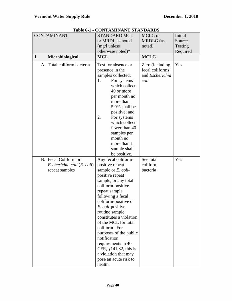
Vermont Water Supply Rule December 1, 2010
Page 40
Table 6-1 - CONTAMINANT STANDARDS CONTAMINANT STANDARD MCL
or MRDL as noted (mg/l unless otherwise noted)*
MCLG or MRDLG (as noted)
Initial Source Testing Required
1. Microbiological MCL MCLG
A. Total coliform bacteria Test for absence or presence in the samples collected: 1. For systems
which collect 40 or more per month no more than 5.0% shall be positive; and
2. For systems which collect fewer than 40 samples per month no more than 1 sample shall be positive.
Zero (including fecal coliforms and Escherichia coli
Yes
B. Fecal Coliform or Escherichia coli (E. coli) repeat samples
Any fecal coliform-positive repeat sample or E. coli-positive repeat sample, or any total coliform-positive repeat sample following a fecal coliform-positive or E. coli-positive routine sample constitutes a violation of the MCL for total coliform. For purposes of the public notification requirements in 40 CFR, §141.32, this is a violation that may pose an acute risk to health.
See total coliform bacteria
Yes

Vermont Water Supply Rule December 1, 2010
Page 41
CONTAMINANT STANDARD MCL or MRDL as noted (mg/l unless otherwise noted)*
MCLG or MRDLG (as noted)
Initial Source Testing Required
Giardia lamblia ---- zero Only if MPA testing required
Viruses --- zero No
Legionella --- zero No
Cryptosporidium --- zero Only if MPA testing required
2. Turbidity Yes
A. Unfiltered systems required to install filtration
See 40 CFR, §141.13 --- ---
B. Unfiltered systems that have been granted approval for avoiding filtration
See 40 CFR, §141.71 --- ---
C. Conventional, Direct, Slow Sand, Diatomaceous earth filtration and other filtration technologies
See 40 CFR, §141.73 --- ---
3. Primary Inorganic Chemicals
MCL MCLG
Arsenic 0.010 mg/l zero Yes
Asbestos 7 million fibers/liter (longer than 10 um)
7 million fibers/liter (longer than 10 um)
No
Barium 2 mg/l 2 mg/l Yes
Cadmium 0.005 mg/l 0.005 mg/l Yes
Chromium 0.1 mg/l 0.1 mg/l Yes
Copper 1.3 mg/l (Action Level)
1.3 mg/l Yes
Fluoride 4.0 mg/l 4.0 mg/l Yes
Lead 0.015 mg/l (Action Level)
zero Yes

Vermont Water Supply Rule December 1, 2010
Page 42
CONTAMINANT STANDARD MCL or MRDL as noted (mg/l unless otherwise noted)*
MCLG or MRDLG (as noted)
Initial Source Testing Required
Mercury 0.002 mg/l 0.002 mg/l Yes
Nitrate 10.0 (as Nitrogen) 10mg/l (as Nitrogen)
Yes
Nitrite 1.0 (as Nitrogen) 1 mg/l (as Nitrogen)
Yes
Total nitrate & nitrite 10.0 (as Nitrogen) 10 mg/l (as Notrogen)
Yes
Selenium 0.05 mg/l 0.05 mg/l Yes
Antimony 0.006 mg/l 0.006 mg/l Yes
Beryllium 0.004 mg/l 0.004 mg/l Yes
Cyanide (as free cyanide) 0.2 mg/l 0.2 mg/l Yes
Nickel 0.1 mg/l 0.1 mg/l Yes
Thallium 0.002 mg/l 0.0005 mg/l Yes
4. Disinfection By-products
MCL MCLG
Bromodichloromethane Dibromochloromethane Tribromethane
(Bromoform) Trichloromethane
(Chloroform)
Sum of all concentrations (Total Trihalomethanes): 0.080 mg/l
zero 0.06 mg/l zero -----
No
Monochloroacetic acid Dichloroacetic acid Trichloroacetic acid Monobromoacetic acid Dibromoacetic acid
Sum of all concentrations (Haloacetic acids (five) HAA5): 0.060 mg/l
--- zero 0.3 mg/l --- ---
No
Bromate (systems treating with ozone)
0.010 mg/l zero No
Chlorite (systems treating with chlorine dioxide)
1.0 mg/l 0.8 mg/l No
5. Disinfectant residuals MRDL MRDLG
Chlorine 4.0 mg/l (as Cl2) 4 mg/l (as Cl2) No
Chloramines 4.0 mg/l (as Cl2) 4 mg/l (as Cl2) No
Chlorine Dioxide 0.8 mg/l (as Cl2) 0.8 mg/l (as Cl2)
No
6. Volatile Organic Chemicals
MCL MCLG

Vermont Water Supply Rule December 1, 2010
Page 43
CONTAMINANT STANDARD MCL or MRDL as noted (mg/l unless otherwise noted)*
MCLG or MRDLG (as noted)
Initial Source Testing Required
Vinyl Chloride 0.002 mg/l zero Yes
Benzene 0.005 mg/l zero Yes
Carbon Tetrachloride 0.005 mg/l zero Yes
1,2-Dichloroethane 0.005 mg/l zero Yes
Trichloroethylene 0.005 mg/l zero Yes
para-Dichlorobenzene 0.075 mg/l 0.075 mg/l Yes
1,1-Dichlorethylene 0.007 mg/l 0.007 mg/l Yes
1,1,1-Trichloroethane 0.2 mg/l 0.2 mg/l Yes
cis-1,2-Dichloroethylene 0.07 mg/l 0.07 mg/l Yes
1,2-Dichloropropane 0.005 mg/l zero Yes
Ethylbenzene 0.7 mg/l 0.7 mg/l Yes
Monochlorobenzene 0.1 mg/l 0.1 mg/l Yes
o-Dichlorobenzene 0.6 mg/l 0.6 mg/l Yes
Styrene 0.1 mg/l 0.1 mg/l Yes
Tetrachloroethylene 0.005 mg/l zero Yes
Toluene 1 mg/l 1 mg/l Yes
trans-1,2-Dichloroethylene 0. 1 mg/l 0.1 mg/l Yes
Xylenes (total) 10 mg/l 10 mg/l Yes
Dichloromethane 0.005 mg/l zero Yes
1,2,4-Trichlorobenzene 0.07 mg/l 0.07 mg/l Yes
1,1,2-Trichloroethane 0.005 mg/l 0.003 mg/l Yes
7. Synthetic Organic Chemicals
MCL MCLG
Alachlor 0.002 mg/l zero Yes
Atrazine 0.003 mg/l 0.003 mg/l Yes
Carbofuran 0.04 mg/l 0.04 mg/l Yes
Chlordane 0.002 mg/l zero Yes
Dibromochloropropane 0.0002 mg/l zero No

Vermont Water Supply Rule December 1, 2010
Page 44
CONTAMINANT STANDARD MCL or MRDL as noted (mg/l unless otherwise noted)*
MCLG or MRDLG (as noted)
Initial Source Testing Required
2,4-D 0.07 mg/l 0.07 mg/l Yes
Ethylene Dibromide 0.00005 mg/l zero Yes only for groundwater sources
Heptachlor 0.0004 mg/l zero Yes
Heptachlor Epoxide 0.0002 mg/l zero Yes
Lindane 0.0002 mg/l 0.0002 mg/l Yes
Methoxychlor 0.04 mg/l 0.04 mg/l Yes
Polychlorinated biphenols 0.0005 mg/l zero Yes
Pentachlorophenol 0.001 mg/l zero Yes
Toxaphene 0.003 mg/l zero Yes
2,4,5-TP Silvex 0.05 mg/l 0.05 mg/l Yes
Benzo[a]pyrene 0.0002 mg/l zero Yes
Dalapon 0.2 mg/l 0.2 mg/l No
Di(2-ethylhexyl) adipate 0.4 mg/l 0.4 mg/l Yes
Di(2-ethylhexyl) phthalate 0.006 mg/l zero Yes
Dinoseb 0.007 mg/l 0.007 mg/l Yes
Diquat 0.02 mg/l 0.02 mg/l No
Endothall 0.1 mg/l 0.1 mg/l No
Endrin 0.002 mg/l 0.002 mg/l Yes
Glyphosate 0.7 mg/l 0.05 mg/l No
Hexachlorobenzene 0.001 mg/l zero Yes
Hexachlorocyclopentadiene 0.05 mg/l 0.05 mg/l Yes
Oxamyl (Vydate) 0.2 mg/l 0.2 mg/l Yes
Picloram 0.5 mg/l 0.5 mg/l Yes
Simazine 0.004 mg/l 0.004 mg/l Yes
2,3,7,8-TCDD (Dioxin) 3 x 10⁻⁸ mg/l zero No
8. Radionuclides MCL MCLG

Vermont Water Supply Rule December 1, 2010
Page 45
CONTAMINANT STANDARD MCL or MRDL as noted (mg/l unless otherwise noted)*
MCLG or MRDLG (as noted)
Initial Source Testing Required
Gross Alpha Particle Activity (including radium-226 but excluding radon and uranium)
15 pCi/l zero Yes
Combined Radium-226 and Radium-228
5 pCi/l2 zero Yes
Uranium 20 ug/l zero Yes
Beta particle and photon radioactivity from man-made Radionuclides1
An annual dose equivalent to the total body or any internal organ greater than 4 millirem/year (mrem/year)3
zero No
Gross Beta Activity1 50 pCi/l --- No
Tritium1 20,000 pCi/l4 --- No
Strontium-901 8 pCi/l5 --- No
8. Treatment Technique MCLG
Acrylamide ---- zero No
Epichlorohydrin ---- zero No * The conversion from mg/l to ug/l is 1 mg/l=1000 ug/l. As an example 5 mg/l is equal to 5000 ug/l 1 Public Community Water Systems designated by the Secretary as vulnerable must sample for this
contaminant 2 The combined radium-226 and radium-228 value is determined by the addition of the results of the
analysis for radium-226 and radium 228. 3 See 40 CFR §141.66(d) for calculation of the MCL. 4 Average annual concentration assumed to produce a total body or organ doses of 4 mrem/yr. For tritium the
critical organ is total body. See 40 CFR §141.66. 5 Average annual concentration assumed to produce a total body or organ doses of 4 mrem/yr. For strontium-
90 the critical organ is bone marrow. See 40 CFR §141.66. 6.13 Secondary Standards (a) All new Public Community, Domestic Bottled, and Public Non-Transient Non-
Community water systems shall initially monitor for the Secondary Standards contained in 40 CFR, Part 143 except for Aluminum, Copper, Fluoride, Foaming Agents, Silver, Sulfate, and Zinc. Proposed water systems with contaminants exceeding these values may be required to treat or abandon the source, at the discretion of the Secretary.

Vermont Water Supply Rule December 1, 2010
Page 46
(b) Existing Public Community, Bottled, and Public Non-Transient Non-Community water systems may be required to monitor and comply with the Secondary Standards contained in 40 CFR, Part 143 when, in the judgment of the Secretary, compliance is necessary to protect the public welfare. Table 6-2 summarizes these secondary contaminants and the standards which apply to Public Community, Bottled, and Public Non-Transient Non-Community water systems. If any discrepancy exists between the values in Table 6-2 with the exception of sodium and aluminum and the referenced sections in 40 CFR, Part 143, then the standards in 40 CFR, Part 143 shall apply.
Table 6-2
SECONDARY CONTAMINANT STANDARDS
CONTAMINANT STANDARDINITIAL SOURCE TESTING REQUIRED?
Aluminum 0.2 mg/l No
Chloride 250 mg/l Yes
Color 15 color units Yes
Copper 1.0 mg/L Yes as Primary Contaminant
Corrosivity
Non-corrosive(between +0.5 and -0.5 Langelier
Saturation Index) Yes
Fluoride 2.0 mg/L Yes as Primary Contaminant
Foaming Agents 0.5 mg/l No
Iron 0.3 mg/l Yes
Manganese 0.05 mg/l Yes
Odor 3 threshold odor number Yes
pH 6.5 – 8.5 Yes
Silver 0.1 mg/l No
Sodium 250 mg/l Yes
Sulfate 250 mg/l No
Total dissolved solids (TDS) 500 mg/l Yes
Zinc 5 mg/l No (c) Existing Public Community and Non-Transient Non-Community water systems using
groundwater sources shall monitor for Iron and Manganese once every three years. Additional monitoring may be required at the discretion of the Secretary.
(d) Additional monitoring requirement for Public Transient Non-Community water
systems are contained in Appendix A Part 11.

Vermont Water Supply Rule December 1, 2010
Page 47
6.14 Maximum Contaminant Level Goals (MCLGs) The Maximum Contaminant Level Goals (MCLGs) contained in 40 CFR Part 141 are herein adopted (see Table 6-1 and Section 6.12). The MCLGs in the referenced sections of 40 CFR Part 141 shall apply throughout the entire Public water system. A maximum contaminant level goal shall serve as the basis for design for any proposed treatment units using best available technology on existing water systems and sources. Maximum contaminant level goals shall serve as the basis for design for new Public water systems. Where feasible, new sources shall meet maximum contaminant level goals without treatment. 6.15 Health Advisories For contaminants which may be detected in a Public water system for which MCLs or MCLGs have not been adopted, and the Vermont Commissioner of Health has established a Vermont Health Advisory Level for it, the Secretary may adopt the Advisory Level as an MCL or MCLG. 6.16 Treatment Techniques 6.16.1 All Public water systems shall comply with the acrylamide and epichlorohydrin
provisions of 40 CFR, Part 141, Subpart K, Treatment Techniques.

Vermont Water Supply Rule December 1, 2010
Page 48
Subchapter 21-7 FACILITY AND OPERATION REQUIREMENTS Introduction This subchapter applies to the following water systems: (a) Public Community water systems; (b) Public Non-Transient Non-Community (NTNC) water systems; (c) Public Transient Non-Community (TNC) water systems; and (d) Domestic Bottled water systems. The design, construction, installation, extension, modification, location, maintenance and operation of all Public water systems and bottled water and bulk water plants or parts thereof shall comply with the requirements of this rule, Appendices A through D, and the relevant sections of 40 CFR, Part 141 as provided below. 7.1 Operation & Maintenance 7.1.1 All Public water systems except Transient Non-Community water systems shall have
an Operation and Maintenance Manual approved by the Secretary and shall be operated in a manner consistent with the approved Operation & Maintenance Manual (See Appendix D). Transient Non-Community water systems with treatment are recommended to have an Operation and Maintenance Manual and to operate in accordance with it.
7.1.2 All water storage tanks shall be comprehensively inspected, inside and out, every 5 years,
except for newly constructed, newly painted (inside), or newly reconditioned tanks (inside and outside), which shall be inspected within 10 years of service and every 5 years thereafter. The inspection of the outside of a buried or partially buried tank may be limited to exposed portions. The inspection, findings, and servicing documentation shall be retained in the water system’s files for review upon request.
7.2 Disinfection 7.2.1 Disinfection facilities are required of all Public Community and Non-Transient Non-
Community water systems. Public Community and Non-Transient Non-Community water systems shall have the capability of continuous disinfection. Public water systems shall conform to the disinfection provisions of 40 CFR, §141.72. Disinfection shall be administered as described in Subpart 4.3 of Appendix A.
7.2.2 Continuously operating disinfection is required by the Secretary for all surface water
sources and for groundwater sources under the direct influence of surface water. The Secretary may require intermittent or continuously operating disinfection for any other Public water system, when he or she determines it necessary for the protection of public

Vermont Water Supply Rule December 1, 2010
Page 49
health, including but not limited to sources determined to be vulnerable to pathogenic contamination (see Section 6.2).
7.2.3 Public water systems which provide filtration must provide disinfection treatment as
required by 40 CFR, §141.72(b)(1)(2)(3). Residual disinfectant concentration of the finished water shall be monitored as required by 40 CFR, §141.74(c)(2)(3).
7.2.4 As also stated in Appendix A 5.2.2, all products or chemicals which may come in contact
with water intended for use in a Public water system shall meet American National Standards Institute/NSF International Standards, specifically ANSI/NSF Standards 60 and 61.
7.2.5 Disinfection facilities are recommended for all Transient Non-Community water
systems. 7.3 Fluoridation 7.3.1 Public water systems which add fluoride to drinking water for dental health purposes, in
addition to complying with the maximum contaminant levels established in Subchapter 21-6, shall control the level of fluoride within the following ranges:
Low Target High 1.0 ppm 1.1 ppm 1.6 ppm
7.3.2 Water systems that add fluoride shall test to determine the amount of fluoride in the
finished water at least once per day, or more often if required by the Secretary.
(a) Residual testing equipment shall enable measurement of fluoride to the nearest 0.2 mg/l in the range from 0.0 mg/l to 4.0 mg/l.
(b) Analyses for fluoride residual shall be conducted in accordance with the analytical recommendations set forth in the latest edition of Standard Methods for the Examination of Water and Wastewater, American Public Health Association, unless otherwise approved by the Secretary.
(c) Results of daily fluoride tests shall be reported to the Secretary in accordance with Subchapter 21-9.
7.3.3 Secondary Controls Secondary control systems for fluoride chemical feed devices shall be required by the Secretary as a means of reducing the possibility for overfeed or for pacing fluoride delivery to water flow. These may include flow or pressure switches or other devices. 7.4 Corrosion Control
Vermont Water Supply Rule December 1, 2010
Page 50
7.4.1 Public Community and Public Non-Transient Non-Community water systems shall implement corrosion control programs in compliance with 40 CFR, Part 141, Subpart I, Control of Lead and Copper.
7.5 Sanitary Surveys 7.5.1 All Public water systems must comply with the Sanitary Survey provisions of 40 CFR,
§141.21(d), 40 CFR §141.401, 40 CFR §141.536, 40 CFR §141.711, 40 CFR §141.716, and 40 CFR §141.723.
7.6 Source Protection 7.6.1 All Public Community, Domestic Bottled, and Public Non-Transient Non-
Community water systems shall have a Source Protection Plan approved by the Secretary and shall maintain the plan as required in Subchapter 21-16. Public Transient Non-Community water systems are encouraged to develop and maintain a Source Protection Plan.
7.6.2 Standards and Criteria for Source Protection. Standards and Criteria for Source Protection Plans covered under this subchapter shall follow the criteria and standards for source protection as set forth in Subchapter 21-16 and in the statutory requirements of 10 V.S.A., Chapter 56. 7.7 Adequate Water Supply Required 7.7.1 A Public water system shall provide an adequate supply of potable water during average
and peak user demand periods on a sustained basis to all users. 7.7.2 If a Public water system is unable to reliably and consistently produce an adequate
supply of potable water from permitted non-emergency sources to meet normal and peak demands, the owner shall immediately begin planning for and implementing the development and connection of new permitted sources to meet average and peak user demands.
7.7.3 When user demand exceeds supply, the owner shall, on an emergency short-term basis,
take appropriate action to reduce nonessential demand. Reduction of demand shall be considered as an emergency response achievable by directive from the water system to its users, which may include the implementation of water conservation practices and the prohibition of water use for nonessential purposes (e.g., lawns, gardens, vehicle washing).
7.7.4 When a water system does not have an adequate supply for its users, the Secretary may
require the Public water system to supply potable water through other means, including but not limited to, bottled water, bulk water, and development of a new source, or to impose mandatory water conservation measures.

Vermont Water Supply Rule December 1, 2010
Page 51
7.8 OSHA and VOSHA Compliance All Public water system facilities and operations shall comply with OSHA and VOSHA regulations, as applicable, including but not limited to confined space posting and entry requirements, chemical storage and handling, electrical safety, personal protective equipment, fall protection, lockout and tagout procedures, excavation safety, stairway and ladder safety, record keeping, reporting, and training. This section does not impose more stringent requirements than is independently imposed on water systems by OSHA/VOSHA regulations. 7.9 Composite Correction Program The Secretary may require a Public water system to conduct a Composite Correction Program (CCP) and to require that the Public water system implement any follow-up recommendations that result as part of the CCP. The CCP consists of two elements—a Comprehensive Performance Evaluation (CPE) and Comprehensive Technical Assistance (CTA). A CPE is a thorough review and analysis of a plant’s performance-based capabilities and associated administrative, operation and maintenance practices. It is conducted to identify factors that may be adversely impacting a plant’s capability to achieve compliance and emphasizes approaches that can be implemented without significant capital improvements. A CTA is the performance improvement phase that is implemented if the CPE results indicate improved performance potential. During the CTA phase, the system must identify and systematically address plant-specific factors. The CTA is a combination of utilizing CPE results as a basis for follow-up, implementing process control priority-setting techniques and maintaining long-term involvement to systematically train staff and administrators.

Vermont Water Supply Rule December 1, 2010
Page 52
Subchapter 21-8 CROSS CONNECTION CONTROL Introduction This subchapter applies to the following water systems: (a) Public Community water systems; (b) Public Non-Transient Non-Community (NTNC) water systems; (c) Public Transient Non-Community (TNC) water systems; (d) Bottled water systems; and (e) Non-Public water systems requiring permits. 8.1 Cross Connections 8.1.1 No physical connection, unless approved by the Secretary, shall be permitted between the
distribution system of a Public or Non-Public water system and any pipes, pumps, hydrants, tanks or other water systems whereby contaminated or polluted water or other contaminating substances may be discharged or drawn into the Public and Non-Public water system. Any physical connection with a non-potable source of water shall include an adequate backflow prevention device which meets the requirements of American Water Works Association Standards.
8.1.2 Where an investigation or inspection by a Public or Non-Public water system discloses
that a cross connection exists, the water supplier shall take immediate action to completely eliminate the cross connection.

Vermont Water Supply Rule December 1, 2010
Page 53
Subchapter 21-9 REPORTING REQUIREMENTS AND RECORD KEEPING Introduction This subchapter applies to the following water systems: (a) Public Community water systems; (b) Public Non-Transient Non-Community (NTNC) water systems; (c) Public Transient Non-Community (TNC) water systems; and (d) Domestic Bottled water systems. 9.1 Reporting 9.1.1 Except where a shorter period is specified in 40 CFR, Part 141 Subpart D, the water
supplier shall report to the Secretary the results of any test measurement or analysis required by 40 CFR Part 141 within the first ten days following the month in which the result is received or the first ten days following the end of the required monitoring period as stipulated by the Secretary, whichever is shortest. Reporting shall be conducted in accordance with the applicable sections of 40 CFR, Part 141, Subpart D, Reporting and Record Keeping requirements. Additional reporting is required by Subsection 9.1.2 of this subchapter, below.
9.1.2 All Public Water Systems providing treatment and all Public Community water systems
shall submit a signed report to the Secretary at least once a month (or as otherwise directed by the Secretary) no later than ten (10) days following the end of the month, with the following information, as applicable.
(a) A summary of the water system operation, including the amount of water
produced or purchased; (b) Results of water temperature measurements; (c) Results of all turbidity analyses; (d) Results of chlorine residual analyses; (e) Results of fluoride residual analyses; (f) Results of pH analyses; (g) Calculated CT values for highest peak hourly flow during the month; and (h) Any other information specified by the Secretary as a condition of a permit or
temporary permit to operate. The summary shall be submitted either on a form or in digital format prescribed by or approved by the Secretary. All laboratory test results submitted shall include copies of the original test reports on the letterhead of the laboratory which performed the analyses unless other arrangements have been approved by the Secretary.

Vermont Water Supply Rule December 1, 2010
Page 54
9.1.4 The water supplier shall notify local law enforcement officials and the Secretary immediately upon discovering a threat to water quality or quantity due to vandalism, tampering, verbal or written threat, or sabotage.
9.1.5 Public Transient Non-Community water systems shall report water system
administrative and operation information annually to the Secretary on a form provided by the Secretary.
9.2 Record Keeping 9.2.1 Record maintenance shall be conducted in accordance with 40 CFR, §141.33, Record
Maintenance.
Vermont Water Supply Rule December 1, 2010
Page 55
Subchapter 21-10 PUBLIC NOTIFICATION
Introduction This subchapter applies to the following water systems: (a) Public Community water systems; (b) Public Non-Transient Non-Community (NTNC) water systems; (c) Public Transient Non-Community (TNC) water systems; and (d) Bottled water systems. 10.1 General Notification Requirements 10.1.1 All Public water system suppliers shall give public notification in accordance with 40
CFR, Part 141, Subpart Q, Public Notification of Drinking Water Violations, including the standard health effects language for public notification in Appendix B to Subpart Q of Part 141; and 40 CFR, Part 141, Subpart S, Ground Water Rule §141.403(a)(7) Special notice to the public of significant deficiencies or source water fecal contamination.
10.1.2 All Public water systems required to provide public notice for a Temporary Operating
Permit under Subchapter 5.4 of this rule shall provide public notice at least annually stating the reasons for an issuance of the Temporary Operating Permit. These notices shall follow the requirements of this subchapter. Public Community water suppliers may provide notice of their Temporary Operating Permit in their annual consumer confidence report.
10.2 Other Notification Requirements 10.2.1 For any required public notification not covered by 40 CFR, Part 141, Subpart Q, or by
the Water Supply Rule (e.g., variances from technical standards, conditions of permits, notices of alleged violations), or when the Secretary determines, in his or her judgment, public notification is necessary for the protection of public health, a Public water system shall provide the public notification prescribed by the Secretary. The water supplier shall be notified by the Secretary of the particular notification requirements. The Secretary shall use the information on record from the respective water system to provide the water system with the notification.
10.2.2 The Secretary may prescribe the content of the notice, the method of distribution, and the
time to issue the notice. 10.2.3 The Secretary may modify the requirements of this subchapter, or require additional
public notification measures (e.g., Boil Water notices, Do Not Drink notices, or other language) when necessary, in his or her judgment, to inform consumers of the water for protection of public health. Such additional measures may include other forms of notification and specific language in the notice.

Vermont Water Supply Rule December 1, 2010
Page 56
10.2.4 The water supplier shall accomplish notification as prescribed by the Secretary depending
on the type of system and population served. The water supplier shall give a copy of any current public notice to all new billing units or new hookups no later than the time service begins.
The Secretary may require any combination of the following forms of notification that he or she deems are necessary to adequately inform the consumers: (a) Through publication in a daily newspaper of general circulation in the area served
by the system. If the area served is not covered by a daily newspaper of general circulation, notice shall be given by publication in a weekly newspaper of general circulation in the area served;
(b) Through announcement on local radio stations or television stations; (c) Through posting of the notice in conspicuous locations in the service area; (d) Through written notice to each user by mail, included with the water bill, or by
hand delivery; or (e) Through any other means determined by the Secretary to provide effective notice.
10.2.5 When the condition(s) requiring public notification continue in effect, the water supplier
shall make repeat notification as prescribed by the Secretary. 10.2.6 When a water supplier is required to issue a public water notice, the system shall notify
consumers within the time prescribed by the Secretary. All notices required by the Secretary shall use the language and format provided by the Secretary. All notice language shall be presented in a plainly visible manner. Any deviations from the prescribed notice language or format must be approved by the Secretary.
10.3 Certification of Notice Within ten days of issuance of a required public notice, the water system owner shall submit to the Secretary a certification that it has fully complied with the public notification requirements, on a form supplied by the Secretary. The water system owner shall include with the certification a representative copy of each type of notice distributed, published, posted, and made available to the persons served by the system and to the media. 10.4 Notice by Secretary In addition to these requirements, the Secretary may issue any notice(s) he or she determines is necessary to inform consumers and the general public of possible public health risks or hazards. 10.5 Consumer Confidence Reports All Public Community water suppliers shall prepare and directly deliver an annual consumer confidence report on the quality of the water by July 1 of each year to the customers of the water system. The report shall be based on the immediately preceding calendar year. All Public Community water systems shall comply with the provisions of 40 CFR, Part 141, Subpart O

Vermont Water Supply Rule December 1, 2010
Page 57
Consumer Confidence Reports including Appendix A to Subpart O of Part 141 –Regulated Contaminants and the following requirements. 10.5.1 A copy of the report and a certification statement, stating that the report was directly
delivered to all customers, shall be sent to the Water Supply Division no later than July 1 of each year.
10.5.2 The report shall include, but not be limited to:
(a) Information about the source, or sources; (b) Definitions; (c) Information on detected contaminants displayed in a table; (d) Information on Cryptosporidium, radon, and other contaminants; (e) Compliance status with state and federal regulations; (f) Variances and exemptions; (g) A brief explanation regarding contaminants found in drinking water; (h) Telephone number of the owner, operator, or water system designee; (i) Information about opportunities for public participation; (j) Required additional
health information; and (k) Any other reporting requirements established by the Secretary in addition to those
identified here.

Vermont Water Supply Rule December 1, 2010
Page 58
Subchapter 21-11 BOTTLED & BULK WATER Introduction This subchapter applies to the following water systems: (a) Public Community water systems; (b) Public Non-Transient Non-Community (NTNC) water systems; (c) Public Transient Non-Community (TNC) water systems; and (d) Bottled water systems. Additionally, this subchapter applies to persons who distribute or transport bulk water intended for human consumption or other consumer uses. Bottled or bulk water intended for human consumption and other consumer uses meets the definition of drinking water at 10 V.S.A., §1671, and therefore is regulated by this rule. The public distribution and sale of bottled water shall be permitted by the Secretary before such water is sold or delivered in Vermont. Facilities which produce bottled water, Bottled water systems, are considered Public water systems and shall meet all the applicable requirements of this rule, including the Appendices. 11.1 Bottled Water 11.1.1 Scope No person shall process, package or provide bottled water for sale or distribution in Vermont unless the water meets the standards established in this rule and a Permit to Operate a Bottled water system has been obtained from the Secretary. 11.1.2 Procedures (a) Any person desiring to operate a water bottling facility in Vermont shall submit a
complete, signed application on a form provided by the Secretary. (b) All bottled water shall be filtered, processed, and packaged in accordance with the
Federal Food and Drug Administration Good Manufacturing Practice Regulations (GMPRs) as found in 21 CFR, Parts 110 and 129, in addition to the requirements of this rule. The Bottled water system shall certify to the Secretary that they are in compliance with the Federal Food and Drug Administration GMPRs.
(c) If the Bottled water system is in another state or country (i.e., an imported Bottled water
system), a statement from the appropriate regulatory agency with jurisdiction over the Bottled water system indicating that the facility has been approved to bottle or package water for human consumption shall be submitted. This approval may be in the form of a copy of a certificate, license, permit, or a letter of approval from the agency. The Secretary may require the Bottled water system to submit of a copy of the laws and

Vermont Water Supply Rule December 1, 2010
Page 59
regulations on bottled water processing from the regulatory agency having jurisdiction. In accordance with 10 VSA §1673(f)(1), an imported Bottled water system shall certify that the water and the source and system of the imported water is regulated by drinking water standards or requirements substantially equivalent to or more stringent than standards or requirements established by the Secretary pursuant to 10 VSA §1672(b).
(d) For any proposed or new Bottled water system, a Bottled Water Permit to operate
application shall be submitted on forms provided by the Secretary. The application shall include, but not be limited to: (1) (1) for domestic Bottled water systems, proof that a Source Permit and Construction
Permit were issued by the Secretary; (2) methods employed in the bottling operation; (3) recall plan; (5) water quality data (see (h) below); (6) for Bottled water systems with a source(s) in Vermont, a source protection plan,
if it was not submitted to the Secretary as part of a Source Permit; (7) water treatments used; (9) a flow diagram from the source through the bottling operation; (10) A label for each container size of the bottled water product that is to be permitted
which contains the information in Subsection 11.1.2(g).
(e) For Bottled water systems with a current Permit to Operate a Bottled Water System, a renewal application shall be submitted on forms provided by the Secretary prior to the expiration of the current permit. This submittal shall include updates of the information listed in 11.1.2(d).
(f) A Bottled water system shall submit any modification to the labels prior to sale or
distribution. (g) All bottled water labels shall contain the following information:
(1) The name of the person or company bottling the water; (2) Town and state in which the water is bottled; (3) Town and state where the source is situated; and (4) Source, i.e. private spring, private well or the name of the Public water system
supplying the water. (h) A complete inorganic chemical, organic chemical, microbiological, and radiological
analysis of contaminants as for Public Community Water Systems as listed in 40 CFR, Part 141 shall be performed on each Bottled water system source(s) prior to bottling (raw water) and each finished bottled water product type and package size to be distributed in Vermont (finished water). Results of these analyses shall be submitted with the application and repeated at the interval specified below. The Secretary may require additional monitoring for protection of the public health and welfare. The Bottled water system shall comply with the requirements of Subsection 6.1.

Vermont Water Supply Rule December 1, 2010
Page 60
Table 11-1 - BOTTLED WATER MONITORING REQUIREMENTS
Type of Analysis(1) Sampling Frequency
Number of Samples
Source Product
Microbiological(2) Total Coliform Heterotrophic Plate Count (HPC)(3)
Monthly Monthly
1 1
4 4
Primary Inorganic Chemicals
3 Years 1 1
Volatile Organic Chemicals 3 Years 1 1
Synthetic Organic Chemicals
3 Years 1 1
Radionuclides: Gross Alpha, Combined Radium 226 & 228, and Uranium
3 Years 1 1
Disinfectant By-products and Disinfectant Residual
According to 40 CFR, Part 141, Subpart L
(1) See Table 6-1 for a detailed list of contaminants and associated
MCLs and MRDLs. (2) If bottling does not occur monthly, a letter must be submitted in
place of the monthly sample to avoid receiving a monitoring violation.
(3) If HPC is greater than or equal to 500 colony forming units per 1 ml, facility shall investigate the source of contamination and bottling operation.
(i) All analyses required under subsection (h) above shall be performed no earlier than
twelve (12) months prior to applying for a permit to operate a Bottled water system with the exception of the microbiological analyses which shall be performed no earlier than thirty (30) days before the date of the application for a permit to operate.
(j) A domestic Bottled water system shall be operated in accordance with the Operations
and Maintenance Manual approved by the Secretary (see Appendix D). 11.1.3 Reserved 11.1.4 Operation Requirements In addition to meeting the requirements set forth in this subchapter, all water bottling facilities shall be operated in accordance with the Food and Drug Administration's requirements for bottled water facilities as established in 21 CFR Part 129.

Vermont Water Supply Rule December 1, 2010
Page 61
11.2 Bulk Water 11.2.1 General Requirements Bulk water is potable water for human consumption delivered to the consumer or a Public water system by means other than a pipeline or bottled water. It is typically delivered by tanker truck or trailer. Bulk water delivery is usually limited to emergency or temporary situations except for those bulk water operations permitted by the Secretary to be used as a source for Bottled water systems. If water loading stations are used to fill bulk water tankers, the loading station shall comply with the requirements of Appendix A, Subpart 8.11, Water Loading Stations. 11.2.2 Source Requirements and Water Quality Standards No person shall distribute, transport, or provide bulk water for human consumption or other consumer uses unless: (a) the water is supplied from either a permitted Public Community water system or a
Bottled water system permitted by the Secretary; (b) the water system in Subsection 11.2.2(a) meets the applicable requirements of Subchapter
21-6; (c) the bulk water contains a free chlorine residual between 1.0 ppm and 4.0 ppm, or the bulk
water supplier meets the requirements as specified under Subsection 11.2.3; and (d) other requirements that may be imposed by the Secretary to protect public health and
welfare are met. 11.2.3 Tanker Requirements for Hauling Water (a) No person shall provide bulk water for human consumption unless the water tanker,
water hoses, valves, and other surfaces coming into contact with the water are constructed of smooth, nonabsorbent, corrosion-resistant, and non-toxic material safe for contact with potable water.
(b) A bulk water hauler shall develop and implement a Standard Operating Procedure (SOP)
to ensure and document the sanitary conditions of the bulk water hauling operation for each delivery. This SOP shall outline the frequency and method of the vehicle tank cleaning, Total Coliform Bacteria testing, and Heterotrophic Plate Count (HPC) testing. If the HPC count is greater than or equal to 500 colony-forming units per 1 ml, the bulk water hauler shall investigate and correct the source of contamination. The SOP shall be available to the Secretary upon request.
(c) All bulk water transportation vehicles shall be dedicated to the sole purpose of
transporting drinking water as defined by 10 VSA, Section 1671 and shall meet all the applicable requirements of this rule, including the Appendices (e.g., Filing Station requirements in Appendix A Subpart 8.11 and Finished Water Storage in Appendix A Subpart 7).

Vermont Water Supply Rule December 1, 2010
Page 62
Subchapter 21-12 WATER SYSTEM CLASSIFICATION AND OPERATOR CERTIFICATION Introduction This subchapter applies to the following Public water systems: (a) Public Community water systems; (b) Public Non-Transient Non-Community (NTNC) water systems; (c) Public Transient Non-Community (TNC) water systems; and (d) Domestic Bottled water systems. 12.1 General All Public water systems shall be operated by a certified operator of the appropriate class as defined in this subchapter. A certified operator is one who has met the requirements of this subchapter and has a current, valid certification from the Secretary. All Public Community, Domestic Bottled, and Public Non-Transient Non-Community water systems must have a designated certified operator in responsible charge available at all times. “Available” means based on system size, complexity, and source water quality, a certified operator must be on site or able to be contacted as needed to initiate the appropriate action in a timely manner. For purposes of certifying Public water system operators, each Public water system shall be classified according to degree of treatment, and in the case of Class 4, according to size of population served. The class of operator certification required is dependent upon the classification of such facility. There are five classes of water systems. Classes 1, 2, 3, and 4 apply to water systems with their own source(s) of supply, and Class D applies to systems which distribute water. 12.2 Responsibilities and Duties 12.2.1 Owner’s Responsibilities
12.2.1.1 The owner shall be responsible for compliance with the federal Safe Drinking
Water Act, Vermont statutes, and the regulations developed pursuant to both. 12.2.1.2 The owner shall be a certified operator or shall designate a certified operator(s) to
carry on the daily operations of the system. Such designation shall be in writing and shall be signed by both the certified operator and the owner. A copy of the written designation shall be made available to the Secretary upon request.
12.2.1.3 The owner of any Public Community or Non-Transient Non-Community water
system shall place the direct supervision of the water system under the responsible charge

Vermont Water Supply Rule December 1, 2010
Page 63
of the designated certified operator(s) (see Subsection 12.2.1.2). The owner shall place the certified operator(s) in responsible charge of all quality, quantity, process control, and system integrity decisions involving public health, treatment, storage, distribution, and standards compliance. The certified operator shall hold a valid certification equal to or greater than the classification of the treatment facility and distribution system.
12.2.2 Certified Operator’s Responsibilities The certified operator shall comply with the following requirements as a condition of his or her certification: (a) The certified operator(s) in responsible charge must hold a valid certification equal to or
greater than the classification of his or her water system, including each treatment facility and distribution system, as determined by the Secretary.
(b) The operator in responsible charge shall perform the following duties:
1. Conduct visual inspections of the system’s source, source water protection area, storage facilities, and chemical addition systems at an appropriate frequency giving consideration to the system’s design , location, vulnerability, Operations and Maintenance Manual (see Appendix D), and other relevant factors.
2. Be familiar with all aspects of the treatment and distribution system operation of the water system.
3. Oversee all bacterial monitoring, chemical monitoring, and other monitoring required under this Rule.
4. Review the sample monitoring schedule and locations quarterly. 5. Ensure that all samples are delivered to a certified laboratory in a timely manner. 6. Inspect system within 24 hours of any positive fecal coliform result, positive
Total Coliform repeat sample result, or other water system failures that threaten public health.
7. Notify owner of any violation(s) of this Rule. 8. Ensure the accuracy of water meters and other flow measuring devices. 9. Be responsible for measuring, and recording chemical additions. 10. Operate and maintain chemical feed and all treatment systems. 11. Keep abreast of changes in the drinking water regulations and safety regulations. 12. Fulfill certification and certification renewal requirements. 13. Operate and maintain system in accord with the Operation & Maintenance
Manual. 14. Attend all inspections as requested by state personnel. 15. Oversee source water protection, watershed protection, and other activities
associated with chemical waivers or otherwise required by this Rule. 16. Keep complete and accurate water system records. 17. Carry out all required reporting requirements including submitting a complete
monthly report to the Secretary by the 10th day of the following month. 18. Develop and maintain an accurate site plan showing the water source and
distribution system. 19. Respond to consumer complaints promptly.

Vermont Water Supply Rule December 1, 2010
Page 64
20. Comply with all applicable state and federal statutes, rules and orders governing water system regulation.
21. Conduct all duties with reasonable care and judgment for the protection of public health, public safety, and the environment.
12.3 Operator Certification 12.3.1 To be eligible for operator certification, each applicant must:
(a) Submit an application on a form provided by the Secretary; (b) Meet the educational and experience requirements set forth in Section 12.9; (c) Classes 2, 3, 4 and D shall obtain a passing grade on the certification examination
approved by the Secretary (Class 1 operators need registration only); (d) Pay any required fee; and (e) Satisfy all other state mandated requirements for professional licensing and
certification. 12.3.2 When replacing an operator, the water system owner shall notify the Secretary in writing
within ten (10) days following the date an operator ceases operation of a plant or system, and within ten (10) days after a new operator commences operation of a Public water system.
12.3.3 Whenever a new Public water system is constructed, the water supplier shall employ or
contract with an operator certified in the corresponding class for the new facilities. 12.3.4 When significant modifications are made to an existing Public water system which
change the system's classification, the operator(s) shall obtain a new certificate as required by the improvements.
12.3.5 An operator holding a certification in any class is permitted to operate all facilities in that
class and any lower class. Class 4C is the highest Vermont water operator class. This paragraph does not apply to Class D (distribution only).
12.3.6 A certified operator may move from any Public water system class to the next higher one
if he or she satisfies all of the following: (a) the operator has obtained a passing grade on the examination of the higher class;
and (b) he or she has worked as an operator-in-training for six months in the next higher
class. One year as an operator-in-training shall be required before advancing two or more classes.
12.3.7 Applicants who did not obtain a passing grade on a written certification examination for a
class may be retested at any scheduled examination for the particular class. 12.3.8 In the event an operator's certification is denied, the Secretary will provide the applicant
with written notification of the reasons for such denial. Applicants may appeal the denial in accordance with the provisions of 10 V.S.A., §1680.

Vermont Water Supply Rule December 1, 2010
Page 65
12.3.9 The operator's certification shall be displayed in the office or plant of the system, and
provided for inspection upon reasonable request. 12.4 Revocation or Suspension of Operator Certification (a) The Secretary may suspend or revoke a certificate granted under this section, after notice
and opportunity to be heard, if the Secretary finds that the certificate holder has: (1) submitted or contributed to the submission of materially false or inaccurate
information; or (2) violated any material requirement, restriction, or condition of the certificate
including: (i) the violation of any applicable statute, rule, or order governing water
system regulation; and (ii) the failure to use reasonable care and judgment in the performance of the
operator’s duties. The Secretary shall set forth what steps, if any, may be taken by the certificate holder to reapply for certification if a previous certificate has been revoked.
(b) The applicant may appeal a revocation or suspension as provided in 10 V.S.A., §1680. 12.5 Recertification of Expired Certificates Any operator who fails to renew his or her certificate within sixty days following the expiration date of the certificate may not receive a new certificate until he or she successfully passes the qualifying examination and meets the requirements set forth in Section 12.3.1. 12.6 Operator-in-Training (OIT) 12.6.1 An Operator-in-Training (OIT) certification is required to operate a Public water system
under the direct supervision of a certified operator and may be granted by the Secretary. Application must be made on a form supplied by the Secretary.
12.6.2 Upon written notification by the OIT's supervisor that the OIT has completed the
minimum required operational experience for full certification in the appropriate water system, the Secretary may issue the appropriate operator certificate provided the OIT has satisfied all operator certification requirements of this part.
12.7 Provisional Certification 12.7.1 A Provisional Certificate may be issued by the Secretary to an applicant for the operation
of a specific water system when the applicant has not met the full certification requirements for experience in that water system class. A Provisional Certificate may be issued provided the specific water system has exhausted all reasonable efforts in recruiting a fully certified operator, and the applicant has obtained a passing grade on the operator examination for the particular water system class.

Vermont Water Supply Rule December 1, 2010
Page 66
12.7.2 The Provisional Certificate Application shall be co-signed by the applicant and the owner
for the water system which will be served by the provisionally certified operator. The owner of the water system shall certify that the applicant has had operator training by the manufacturer, consultant, or other certified operator and is capable of operating the specified water system. The Provisional Certificate has the following restrictions: (a) It shall be issued for operation of a single, specific water system; (b) It shall be valid only for a time period equal to the minimum operating experience
requirements identified in Table 12-1 of Section 12.9; and (c) It shall be non-transferable.
12.7.3 To convert from a Provisional to a Full Certificate, applicants must: (a) present evidence of having been employed in a particular water system for a
specific amount of time, to include all time in training with equipment manufacturers, consultants, or other certified trainers/operators (see Table 12-1, of Subsection 12.9; and
(b) present evidence of having obtained a passing grade on an examination for the particular classification being sought and evidence that all other certification requirements have been met (see Subsection 12.2.1).
12.8 Classification of Public Water Systems and Drinking Water Facilities Each Public water system is to be classified by the Secretary as set forth in this rule. There will be five classes, 1 through 4 and D. 12.8.1 Class 1A This class of Public water system includes Transient Non-Community water systems with distribution and using any of the following technologies (a) No treatment; (b) Ion exchange for water softening; or (c) Limestone contactors. 12.8.1.1 Class 1B This class of Public water system includes Transient Non-Community water systems with distribution and using any of the following technologies: (a) Disinfection with chlorine or UV, including standby capability. 12.8.2 Class 2 This class of Public water system includes Public Community, Bottled, and Public Non-Transient Non-Community water systems with distribution and any of the following technologies: (a) No treatment; (b) Disinfection with chlorine or UV; includes systems with standby chlorination;

Vermont Water Supply Rule December 1, 2010
Page 67
(c) Ion exchange for softening; or (d) Limestone contactors. 12.8.3 Class 3 This class of Public water system includes Public Community, Bottled, Public Non-Transient Non-Community, and Public Transient Non-Community water systems with distribution and any of the following technologies: (a) Disinfection by other than chlorine or UV; (b) Sequestering or filtration of manganese or iron; (c) Fluoridation; (d) Corrosion control; (e) pH control; (f) Air stripping; (g) Granular activated adsorption; (h) Ion exchange; or (i) Aeration This class also includes all Public water systems using groundwater determined to be under the direct influence of surface water and which have a filtration waiver. 12.8.4 Class 4 This class of Public water system includes all Public Community, Bottled, Public Non-Transient Non-Community, and Public Transient Non-Community water systems which use surface water, or which have groundwater determined to be under the direct influence of surface water with respect to which a filtration waiver has not been issued. 12.8.4.1 Class 4A1 This class includes distribution plus any of the following treatment technologies: (a) Bag filtration; (b) Cartridge filtration; (c) Membrane filtration; (d) Slow sand filtration; or (e) Other similar technologies, as approved by the Secretary, which do not use coagulants. This class serves all water system populations of 25 or greater. 12.8.4.2 Class 4A, 4B, and 4C This class includes distribution plus rapid sand filtration technology and is further differentiated by population served by the system: 4A, for served populations between 25 and 500; 4B, for served populations between 501 and 3,300; and 4C, for served populations greater than 3,300

Vermont Water Supply Rule December 1, 2010
Page 68
12.8.5 Class D This class of Public water system includes Public Community water systems serving 3,300 people or more and that have only a distribution system. A Class D system purchases its water and does not have any source or treatment associated with it. 12.9 Experience and Education 12.9.1 In determining whether an applicant has the operating experience required for
certification in a particular water system class, the Secretary may consider the following: 1) the period of satisfactory experience as a system operator or OIT; and 2) operating experience accrued in another jurisdiction.
All satisfactory experience as noted above shall be credited toward the total experience required for certification in the particular class for which application is made. Operating experience is defined as time spent at a facility, plant, or system in satisfactory performance of operational duties.
12.9.2 All applicants shall have a high school diploma or a general equivalency diploma (GED).
The Secretary may allow experience and relevant training to be substituted for a high school diploma or GED.
12.9.3 Table 12-1, below, contains the minimum experience requirements for certification. Table 12-1 - OPERATOR CLASSIFICATION REQUIREMENTS Public Water System Class(s)
Class of Operator Operating Experience Required (Yrs)
ALL Operator-in-Training(OIT) NONE ALL Provisional NONE 1A Operator Class 1A NONE 1B Operator Class 1B NONE 2 Operator Class 2 1.5 3 Operator Class 3 1.5 4A1 Operator Class 4A1 2 4A Operator Class 4A 2 4B Operator Class 4B 2.5 4C Operator Class 4C 3 D Operator Class D 1.5 12.9.4 Substitutions for Experience Requirements (a) Substitutions with related schooling or courses may be made for required experience for
Classes 2, 3, 4A1, 4A, 4B, 4C, and D but with the limitation that 50 percent of any stated

Vermont Water Supply Rule December 1, 2010
Page 69
experience requirement must be met by actual on-site operating experience in a plant, system or facility.
(b) Formal Education
(1) High School education cannot be substituted for any experience requirement. (2) Approved relevant formal academic education at the post high school or college
level may be substituted for experience requirement on a year for year basis, subject to the 50 percent limitation described in Subsection 12.9.4(a) above. Thirty (30) semester hours or equivalent educational hours of credit are considered to represent 1 year of formal education.
(c) Operator Training
(1) Specialized operator training courses, seminars, workshops or approved technical conferences may be substituted for experience requirements subject to the 50 percent limitation previously described. Continuing Education Units (CEUs) totaling 30 are considered equal to 1 year.
(d) Partial credit toward operating experience may be given for experience in plant or system
maintenance, in a laboratory, in a different certification category than that which is being applied for, and in related (allied) trades, as determined or approved by the Secretary.
12.10 Certification Renewal 12.10.1 A certified water system operator shall submit to the Secretary, at least 30 days
before the expiration date of the certificate, a completed application on the form approved by the Secretary, including any fee due. The Secretary shall review the application and shall promptly notify the applicant of any deficiencies. If the application is complete, the continuing education requirements of Section 12.11 have been fulfilled, and the Secretary finds no cause under Section 12.3 to deny the application, a renewed certificate shall be issued.
The Secretary intends to provide written notice to operators of their certification renewal date approximately 6 months prior to that date. However, the burden of certification renewal is assumed by the applicant and failure of the Secretary to provide notice shall not constitute a basis for contesting the expiration of an operator certificate.
12.10.2 Certification renewal shall occur on a schedule as shown below and shall be based
on various methods of recertification depending on water system class.

Vermont Water Supply Rule December 1, 2010
Page 70
Class of Certificate
Duration of Certificate, Years
Method of Certification
1A 3 Registration
1B, 2 3 Continuing Education or Retesting
3 3 Continuing Education or Retesting
4A1,4(A,B,C) 3 Continuing Education or Retesting
D 3 Continuing Education or Retesting
12.10.3 Certifications issued under the rule may be for fewer years than shown above, in
order to stagger the renewal dates for more efficient administration of the program. 12.11 Continuing Education 12.11.1 Continuing education requirements for certification renewal are as follows.
(a) Water System Class 1A operators are encouraged to attend at least 3 hours of state approved seminar or other approved instruction each 3 year renewal period.
Water System Class 1B operators shall attend at least 3 hours of a state sponsored seminar or other approved instruction each 3 year renewal period.
(b) Water System Class 2 operators shall attend at least 10 hours of a state sponsored
seminar or other approved instruction each 3 year renewal period. (c) Water System Class 3, 4, and D operators shall attend 20 hours of state sponsored
seminars or other approved instruction each 3 year renewal period. 12.11.2 Documentation of continuing education shall be reviewed by the Secretary to
determine compliance with the continuing education requirements. Documentation will be provided by the applicant for renewal or by the Secretary. Acceptable documentation shall consist of individual course completion certificates (pre-approval of course required) or formal course sign-in sheets for pre-approved courses containing the signature of the applicant confirming attendance.

Vermont Water Supply Rule December 1, 2010
Page 71
Subchapter 21-13 LABORATORY CERTIFICATION Introduction This subchapter applies to the following water systems: (a) Public Community water systems; (b) Public Non-Transient Non-Community (NTNC) water systems; and (c) Public Transient Non-Community (TNC) water systems. 13.1 Certification All laboratories doing analyses which are to be submitted by Public water systems under this rule, must be certified by the Vermont Department of Health and all shall be subject to the laboratory certification provisions of 40 CFR, Part 141, Subpart C, and §142.10(b)(3) and (b)(4).

Vermont Water Supply Rule December 1, 2010
Page 72
Subchapter 21-14 (RESERVED)

Vermont Water Supply Rule December 1, 2010
Page 73
Subchapter 21-15 CAPACITY Introduction This subchapter applies to: (a) Public Community water systems and (b) Public Non-Transient Non-Community (NTNC) water systems. 15.1 General Requirements 15.1.1 All proposed new Public Community and Public Non-Transient Non-Community
water systems, for which applications were submitted on or after October 1, 1999, shall demonstrate technical, managerial, and financial capacity prior to obtaining a Construction Permit or an Operating Permit. A Construction Permit or an Operating Permit shall not be issued until a determination has been made by the Secretary that the water system has demonstrated that it has, and will continue to have over the long term, technical, financial, and managerial capacity. Subchapters 21-4 (Construction Permits) and 21-5 (Operating Permits) identify the necessary information required for submittal as part of permit applications. Appendix A of this rule identifies many of the technical capacity requirements, and Appendix B identifies the managerial and financial capacity requirements.
15.2 Technical Capacity 15.2.1 Technical Capacity shall generally be demonstrated by:
(a) Compliance with Appendix A source water and infrastructure requirements; (b) An approved Operation and Maintenance Manual; (c) The retention of a certified operator; and (d) Approved “as-built” drawings.
15.3 Managerial Capacity 15.3.1 Managerial Capacity shall generally be demonstrated by:
(a) An organizational chart that shows clear lines of authority and responsibility, and identifies a person(s) with decision-making authority;
(b) Proof of appropriate experience and expertise of managerial personnel; and (c) By-laws, policies, and procedures for municipalities, cooperatives, homeowners
associations and other similar organizations that define system and customer responsibilities and demonstrate acceptable management and decision-making processes.
15.4 Financial Capacity 15.4.1 Financial Capacity shall generally be demonstrated by:
(a) Reliable cost and revenue projections that demonstrate revenue sufficiency, and

Vermont Water Supply Rule December 1, 2010
Page 74
(b) Proof of implementation of sound fiscal management and control policies and procedures.
Vermont Water Supply Rule December 1, 2010
Page 75
Subchapter 21-16 SOURCE WATER PROTECTION Introduction This subchapter applies to the following water systems: (a) Public Community water systems; (b) Domestic Bottled; and (c) Public Non-Transient Non-Community (NTNC) water systems. 16.1 General All Public Community, Domestic Bottled water systems, and Non-Transient Non-Community Water Systems shall have an approved Source Protection Plan. The owner shall prepare and submit a Source Protection Plan to the Secretary for approval. Public Transient Non-Community water systems are encouraged, but not required, to complete Source Protection Plans. 16.2 Components of a Source Protection Plan A Source Protection Plan shall consist of a map of the delineated Source Protection Area; an inventory of the potential and actual sources of contamination in the Source Protection Area located on the map; a management plan for the risks from the potential and actual sources of contamination; and a contingency plan. Some parts of the Source Protection Plan may also be required in the Operation and Maintenance Manual (see Appendix D of this rule). 16.2.1 Source Protection Area Maps The Source Protection Plan shall include a topographic map showing: (a) the source(s) identified by name and the Water Supply Division’s Source Number; (b) the Source Protection Area, including any delineated zones; (c) the lots and associated landowners, unless this information is included on a tax or
orthophoto map showing the Source Protection Area; and (d) the location of any potential and actual sources of contamination. 16.2.2 Source Protection Area Delineation For Public Community Water Systems, the Source Protection Area shall be: (a) the area approved by the Secretary; (b) the 3,000 foot fixed radius circle assigned by the Secretary prior to September 24, 1992;
or (c) the area approved by the Vermont Department of Health prior to July 1, 1991. These
approvals do not include restrictions imposed by the Board of Health in Health Orders. Where multiple Source Protection Areas have been delineated for a particular source, only the most current, approved, Source Protection Area shall be in effect.
Vermont Water Supply Rule December 1, 2010
Page 76
Non-Transient, Non-Community water systems with groundwater sources shall delineate a Source Protection Area in accordance with Vermont’s Wellhead Protection Program Guidance Document. Non-Transient, Non-Community water systems with a surface water source or Groundwater Under the Direct Influence of Surface Water source shall use the delineation methodology in Appendix A Part 3 of this Rule. Surface water systems with a 3000 foot radius circle Source Protection Area shall redelineate their Source Protection Area(s) in accordance with Appendix A of this Rule, except for surface water systems using Lake Champlain as a source. Surface water systems using Lake Champlain as a source shall redelineate their Source Protection Areas in accordance with Appendix A of this Rule or in accordance with the EPA approved Assessment Protocol for Great Lakes Sources, dated August 8, 1999. The public water system shall choose which method to use. 16.2.3 Inventory of Potential Sources of Contamination The Source Protection Plan shall include an inventory of all potential and actual sources of contamination within the Source Protection Area. The inventory shall include the type of facility or business and the contact name and address. As required in 16.2.1, a map shall be included showing the location of the potential sources of contamination in relation to the Source Protection Area and the sources. With prior approval of the Secretary, certain potential sources of contamination may be grouped together instead of listed individually. 16.2.4 Assessment of Potential Sources of Contamination The Source Protection Plan shall include an assessment of high, medium, or low risk for the potential source of contamination to affect the public water source(s). The Source Protection Plan shall include justification for the ranking. The actual risk to the source and the health of persons from each contaminant at each activity will be made upon considering the following factors: (a) distance from potential or actual source of contamination to drinking water source; (b) toxicity of contaminants (if chemical); (c) the relative elevation of the bottom of source compared to discharge point or potential
discharge point at the PSOC; (d) level of control exerted over PSOC; (e) volume of contaminant which is, or might be, released at the PSOC; (f) a past, present and ongoing, or a potential discharge; (g) the nature of the soils between the PSOC and the source; (h) the aquifer characteristics, if known; (i) type and severity of illness associated with the PSOC if contaminants are disease causing; (j) source construction integrity;

Vermont Water Supply Rule December 1, 2010
Page 77
(k) detection of chemical or microbiological contaminants; and (l) other factors which might help evaluate the level of risk as high, medium, or low. For Zone 1 of a groundwater source, the risk ranking shall be “high” for any activity identified as a “prohibited land use” in Appendix A Subpart 3.3.1.2(e). For any actual sources of contamination, the risk ranking shall be “high.” 16.2.5 Management Plan of Risk The Source Protection Plan shall contain a plan for managing the potential and actual sources of contamination. This plan shall be directed towards controlling existing potential sources of contamination and, where possible, reducing risks of potential contamination. At a minimum, the water system shall notify all landowners within the Source Protection Area of the Source Protection Plan. Other techniques may include educational efforts on protecting groundwater and surface water, zoning ordinances, purchase of land or conservation easements to protect the drinking water quality, maintaining buffer zones for surface water sources, educating the residents about proper septic systems and storage tank maintenance, developing educational programs for schools, etc. Water systems using Lake Champlain as a source shall include information about watershed protection in their management plan. The Secretary will prepare this information. 16.2.6 Contingency Plan All Source Protection Plans shall include a Contingency Plan. The Contingency Plan shall include, but not be limited to: (a) Identification of alternative drinking water sources, both long and short term; (b) A list of key personnel to be notified in case of a water emergency; and (c) A shut-down/start-up procedure, if one is not already contained in an approved
Operations & Maintenance (O&M) Manual. 16.3 Updates of Source Protection Plans Source Protection Plans shall be updated by the Public Water System every three years. The updates shall be submitted to the Secretary for review and approval. The update shall include, but is not be limited to: (a) Inspection reports of potential sources of contamination; (b) Inventory and assessment of new potential and actual sources of contamination in source
protection area; (c) Map location of new potential and actual sources of contamination; (d) Management plans for new potential sources of contamination; (e) A summary of any remedial or corrective actions taken on potential sources of
contamination; and
Vermont Water Supply Rule December 1, 2010
Page 78
(f) Changes in landowners; key town, county, or state officials; management techniques; source protection area; or other pertinent information.
(g) Pertinent new requirements of state and federal rules which may have been adopted since the last update.
16.4 Financial Assistance 16.4.1 The Secretary may establish a financial assistance program to assist Public Community
and Non-Transient Non-Community water systems in preparing and updating Source Protection Plans and Source Water Assessments.
16.4.2 Any financial assistance program which is established through the Drinking Water State
Revolving Fund will be detailed in the Drinking Water State Revolving Fund’s Intended Use Plan submitted to the United States Environmental Protection Agency.
16.5 Construction of Sewer Lines in Source Protection Areas An owner who also owns sewer lines in its water system’s Source Protection Area shall provide for adequate protection of the source water quality as part of the design and construction of any new sewer lines in the Source Protection Area. The Secretary may develop procedures on sewer line construction standards in Source Protection Areas.

Vermont Water Supply Rule December 1, 2010
Appendices Page 1
APPENDIX A - VERMONT STANDARDS FOR WATER SYSTEM DESIGN,CONSTRUCTION, AND PROTECTION

Vermont Water Supply Rule December 1, 2010
Appendices Page 2
Part 1 SUBMISSION OF PLANS Introduction This Part applies to: (a) Public Community water systems; (b) Public Non-Transient Non-Community water systems; and (c) Domestic Bottled water systems. 1.0 General An application for a Permit to Construct or for a Source Permit must be submitted on an application form supplied by the Secretary. An application must be submitted a minimum of 30 days prior to the date of which action by the Secretary is desired. For larger projects contact the Water Supply Division for typical review times. Preliminary plans and the engineer's report for municipal projects should be submitted for review prior to the preparation of final plans. Approval for construction will not be issued until complete, detailed plans and specifications have been submitted to the Secretary and found to be satisfactory. Documents submitted for consideration of formal approval shall include but not be limited to: (a) general layout, including location plan; (b) detailed plans and specifications; (c) basis of design, including a summary; AND (d) operation requirements, where applicable. 1.1 Permit Application The requirements for filing an application with the Secretary shall include but are not limited to: (a) The owner shall complete and sign the application form; and (b) A brief description shall be provided as part of this form including:
(1) purpose of the project; (2) source of water supply; (3) service classification (commercial, residential, offices, recreational, etc.); (4) estimated average and maximum daily water demand; (5) general description of the proposed water system including length and diameter of
water mains, number of service connections, all other fixtures; and (6) fire protection where provided (i.e. number of hydrants, design fire flow,
building(s) to be sprinkled).
1.2 Engineer's Report The Engineer's Report for water system improvement shall, where pertinent, present the following information: 1.2.1 General Information shall include the following:

Vermont Water Supply Rule December 1, 2010
Appendices Page 3
(a) name and mailing address of the owner; (b) identification of the area to be served on a Vermont orthophoto base tax map; (c) general description of any existing water system or drinking water facilities, including
age, general condition, and adequacy; (d) a letter of allocation from the Public water system serving the project, or Source Permit;
and (e) information on fire protection to be provided, if any. 1.2.2 Extent of Water System, including: (a) description of the nature and extent of the area to be served; (b) provisions for extending the water system to include areas beyond limits of intended
construction; and (c) appraisal of the future requirements for service, including existing and potential
industrial, commercial, institutional, and other water supply needs. 1.2.3 Alternate Plans Where two or more feasible solutions exist for providing Public water system facilities, including connection to an existing Public water system, the applicant shall discuss the alternative plans. Reasons shall be given for selecting the one recommended, including financial considerations, implementability and a comparison of the minimum classification of the water system operator required for operation of each alternative facility. 1.2.4 Design Criteria A summary of complete design criteria shall be submitted for the proposed project containing, but not limited to, the following: (a) safe yield of the source of supply (which may be waived for existing systems with no
history of outages and which will not allow further connections); (b) reservoir surface area, volume and a volume-versus-depth curve, if applicable; (c) area and map of source protection area, including an accurate GPS location of the
source(s); (d) estimated average and maximum day water demands for the design period; (e) number of existing and proposed services; (f) fire fighting requirements; includes volume (gpm), pressure and duration of flow
(minimum of 2 hours required); (g) flash mix, flocculation and settling basin capacities; (h) retention times; (i) unit loading; (j) filter area and the proposed filtration rate; (k) backwash rate; and (l) feeder capacities and ranges. 1.2.5 Soil and Groundwater Conditions, including a description of: (a) the character of the soil through which water mains are to be laid; (b) soil conditions prevailing at sites of proposed structures; and

Vermont Water Supply Rule December 1, 2010
Appendices Page 4
(c) the elevation of highest groundwater in relation to subsurface structures. 1.2.6 Water Use Data to include: (a) a description of the population trends as indicated by available records, and the estimated
population which will be served by the proposed water system or expanded system; (b) present water consumption and the projected average and maximum daily demand,
including fire flow demand (see Appendix A Subpart 1.2.8); and (c) unusual occurrences, including anticipated future industrial or commercial uses. 1.2.7 Hydraulic Analysis A hydraulic analysis shall be performed on all proposed water systems, and may be required on major improvements to existing systems, demonstrating the ability of the system to meet pressure and flow requirements. 1.2.8 Fire Flow Requirements to include: (a) recommendations of the Insurance Services Office, current edition or the local fire
department as to fire flows required in the service area involved; systems used for both fire protection and domestic use must maintain a minimum of 20 psi under fire flow conditions at all points in the distribution system and provide adequate distribution storage to meet both domestic and fire flow requirements (See Appendix A Subpart 7.0.1).
(b) fire flows which will be made available by the proposed or enlarged system; and (c) information of type and connection to the water system required for building sprinkler
systems, including back flow prevention devices meeting the applicable ASSE Standards and AWWA Standard M - 14.
1.2.9 Sewerage System Availability Describe the existing sewerage system and indicate location of existing and known future sewage treatment works, with special reference to their proximity to existing or proposed water system structures which may affect the operation of the water system, or which may affect the quality of the supply. 1.2.10 Source of Water Supply Describe the proposed source or sources of water supply to be developed, the reasons for their selection and provide information as needed to gain a Source Permit as required in Subchapter 21-4. (Provide details of operation when two or more sources are used.) 1.2.11 Proposed Treatment Processes Summarize and establish the adequacy of proposed processes and unit parameters for the treatment of the specific water under consideration. Alternative methods of water treatment and chemical use should be considered as a means of reducing water handling and disposal problems.

Vermont Water Supply Rule December 1, 2010
Appendices Page 5
Pilot studies are required when the proposed treatment deviates from the conventional complete treatment involving coagulation, flocculation, sedimentation and filtration with standard rates. Pilot studies may range from review of pilot studies on similar systems with similar raw water quality to full scale pilot system construction and evaluation. 1.2.12 Waste Disposal Discuss the various wastes from the water treatment plant, their volume, proposed treatment and points of discharge. Disposal of water treatment plant sludge shall occur in a manner that is in accordance with the Agency of Natural Resources requirements. 1.2.13 Automation Provide data supporting the selection of automatic equipment, for treatment plants, including the servicing and operator training to be provided. Manual override must be provided for any automatic controls. 1.2.14 Project Sites: Include a discussion of: (a) the various sites considered and advantages of the recommended one(s); (b) the proximity of residences, industries, and other important establishments and land uses;
and (c) any potential sources of contamination that may influence the quality of the supply or
interfere with effective operation of the water system, such as sewage absorption systems, septic tanks, privies, cesspools, sink holes, sanitary landfills, refuse, garbage, underground storage tanks, hazardous sites, industrial facilities, direct discharge sites, agricultural land use, industrial dumps, etc.
1.2.15 Financing to include: (a) estimated cost of integral parts of the system; (b) projected estimated annual cost of operation; and (c) proposed methods to finance both capital and operating costs. 1.2.16 Future Extensions Summarize planning for future needs and services. 1.3 Plans for Construction Plans for water system improvements shall, where pertinent, provide the following: 1.3.1 General Layout: Include:

Vermont Water Supply Rule December 1, 2010
Appendices Page 6
(a) One (1) copy of plans which are relevant to water system approval such as location of source, storage, if any, storm and waste water sewers, boundaries of area to be served, etc.
(b) The first plan sheets shall contain: 1. Project Title; 2. Complete index of all sheets for the project; 3. Location map including North identification; 4. Legend differentiating between existing and proposed facilities and will be
different for sanitary and storm sewers; 5. Inclusion of professional engineer's seal and signature; and 6. A scale bar will be provided when drawings are to scale.
(c) Plans shall be on nominal 2' X 3' sheets. (d) All sheets shall be legible; each sheet shall have the title of the sheet, project name, name
of the public water system. (e) All revisions shall be so identified and include the registered professional engineer’s seal
and signature. (f) Location and size of existing water mains. (g) Location and nature of existing water system structures and appurtenances affecting the
proposed improvements, noted on one sheet, and location plan showing project location(s) within the municipality.
1.3.2 Plan Sheets shall include: (a) stream crossings, providing profiles with elevations of the stream bed and the normal and
high and low water levels; (b) profiles having a horizontal scale of not more than 100 feet to the inch and a vertical
scale of not more than 20 feet to the inch, with both scales clearly indicated, and plan views having a scale of not more than 50 feet to the inch;
(c) location and size of the property to be used for the source development with respect to known references such as roads, streams, section lines, or streets;
(d) topography and arrangement of present or planned sources, roads, or structures, with contour intervals not greater than two feet, where necessary to detail construction grading and filling;
(e) elevations of the highest known flood level, floor of the structure, upper terminal of protective casings and outside surrounding grade, using a single datum which may be a National Geodetic Vertical Datum or United States Coast and Geodetic Survey, United States Geological Survey or equivalent elevations where applicable as reference;
(f) plat and profile drawings of source construction, showing diameter and depth of drill holes, casing and linear diameters and depths, grouting depths, elevations and designation of geological formations, water levels and other details to describe the proposed well completely;
(g) location of all existing and potential sources of pollution as outlined in Subchapter 21-16 of this Rule;
(h) size, length and identity of sewers, drains and water mains and their locations relative to plant structures, also preferred type of pipe shall be indicated on the plan;
(i) schematic flow diagrams and hydraulic profiles showing the flow through various plant units;

Vermont Water Supply Rule December 1, 2010
Appendices Page 7
(j) piping in sufficient detail to show flow through the plant, including waste lines; (k) locations of all chemical storage areas, feeding equipment and points of chemical
application; (l) all appurtenances, specific structures, equipment, water treatment plant waste disposal
units and points of discharge having any relationship to the plans for water mains and/or water system structures;
(m) locations of sanitary or other potentially contaminating facilities, such as lavatories, showers, toilets, and lockers, when applicable or required by the Secretary;
(n) locations, dimensions, and elevations of all proposed plant facilities; (o) locations of all sampling taps; and (p) adequate description of any features not otherwise covered by the specifications (q) Service connection detail must be provided. Curb stops must be shown on plan drawings,
and they must be incapable of conveying surface loads onto the service line. (r) Any connection between potable water and building sprinkler/fire protection systems
must be shown and a state accepted method of preventing backflow provided. 1.4 Design Specifications Where pertinent complete, detailed technical specifications shall be supplied for the proposed project, including: (a) a program for keeping existing water system facilities in operation during construction of
additional facilities so as to minimize interruption of service (b) construction details including materials, quality control, and testing; (c) laboratory facilities and equipment; (d) the number and design of chemical feeding equipment (see Appendix A Subpart 5.1); and (e) materials or proprietary equipment for sanitary or other facilities including any necessary
back flow or back-siphonage protection and coating and linings in contact with raw, partially treated or finished water.
1.5 Revisions to Approved Plans Any deviations from approved plans or specifications affecting capacity, hydraulic conditions, operating units, the functioning of water treatment processes, or the quality of water to be delivered, must be approved by the Secretary before such changes are made. Revised plans or specifications shall be submitted in time to allow the review and approval of such plans or specifications before any construction work, which will be affected by such changes, is begun. 1.6 Additional Information Required The Secretary may require additional information which is not part of the construction drawings, such as head loss calculations, proprietary technical data, copies of deeds, copies of contracts, etc. 1.7 Record Drawings

Vermont Water Supply Rule December 1, 2010
Appendices Page 8
Record drawings, as built, are required at the completion of each project. These drawings shall be submitted within 60 days of final project completion. Construction details must be certified by the engineer of record.

Vermont Water Supply Rule December 1, 2010
Appendices Page 9
Part 2 GENERAL DESIGN CONSIDERATIONS Introduction This Part applies to: (a) Public Community water systems; and (b) Domestic Bottled water systems. 2.0 General The design of a water system or treatment process encompasses a broad area. Application of this part is dependent upon the type of system or process involved. 2.1 Design Basis The water treatment plant, water system sources, and pump stations shall be designed for maximum day demand at the design year, recommended 20 years hence. Water system treatment plants, for water systems planning on future growth, shall be designed for maximum day demands expected at least 10 years hence. Water mains and transmission lines shall be designed for 50 years projected growth. Public water systems serving fewer than 100 connections, such as condominiums or subdivisions, need only plan for known projected demand. Specific per capita per day demands as outlined in Subpart 2.2, Table A2-1, shall be used to establish initial average day demand. When a water system, expecting future growth, reaches 90% of the capacity of treatment or pumping systems capacity, it shall commence planning for the required additional capacity. When pumping or treatment capacities reach 100%, the water system shall initiate construction of these facilities. 2.2 Water Demand Source yields will be compared against the maximum demands of the water systems to determine the adequacy of the source(s) to meet the expected demand. 2.2.1 Average Day Demands The source’s ability to meet the average day demand is based on pumping 12 hours per day. When a water system’s average day demand is being met by pumping in excess of 12 hours per day at the permitted rate the water system shall immediately apply for additional source capacity. 2.2.1.1 For design of new systems or modification to systems without metered data records, the
average day demands shall be based on the average day flow quantities in Table A2-1. 2.2.1.2 Reduction in average day demands determined using Table A2-1 may be made based on
the results of metered data. Reductions below 60 gal/person/day will not be permitted in

Vermont Water Supply Rule December 1, 2010
Appendices Page 10
residential dwellings. A 10% leakage/aging factor will be added to empirically derived average day demands. Four types of proposals may be presented to determine reductions in the average day demands.
(a) Meter readings on the existing water system:
(1) Must be tabulated on a daily basis for at least one year and readings must represent current usage;
(2) Must include daily population figures or occupancy data when appropriate; and (3) On seasonally occupied dwellings, average day demands must be taken for period
of maximum occupancy. (b) Meter readings on existing similar water systems:
(1) must be similar in population type and usage and must be approved for study by the Secretary, and
(2) two similar water systems should be monitored for at least one year prior to analysis.
(c) Installation of low flow plumbing fixtures, 3.5 gallon or less flush toilets, 3.0 gallon per
minute or fewer showerheads, and faucet aerators will allow for a 10% reduction in design flows as calculated from Table A2-1.
(d) Other proposals, acceptable to the Secretary, on a case by case basis. 2.2.2 Maximum Day Demand When the peaking factor is two (2), meeting the maximum day demand is based on finished water production when pumping 24 hours per day at the same rate (GPM) as needed to meet the average day demand. Maximum day demands are determined as follows: Average day demands x peaking factor = maximum day demands. In the absence of site specific data the peaking factor shall be two (2). Please note that the basis of design, including the definitions for average day demand and maximum day demand differ in Part 11, Small Scale Systems. 2.2.3 Peaking factor 2.2.3.1 The peaking factor on new projects and non-metered existing projects is two (2). 2.2.3.2 The peaking factor, if based on metered data, must be based on the same information and
conditions outlined in Appendix A Subpart 2.2.1.2, and is the ratio of the metered maximum day demand to the metered average day demand. The maximum day demand is the greatest amount of water produced by the water system on a single day during a 12 month period, or other appropriate time period.

Vermont Water Supply Rule December 1, 2010
Appendices Page 11
Table A2-1 - UNITIZED AVERAGE DAY FLOWS
Engineering Design Criteria Unitized Average Day Flow Quantities
ESTABLISHMENT DESIGN VALUE
Gallons Per Person Per Day(Unless otherwise noted below)
Assembly Areas, Conference Rooms 5
Airports 5
Bathhouses 5
Bowling Alley (no food service) 75 Per Lane
Camps:
Campground with central comfort stations (4 people per site
100 Per Site
With flush toilets, no showers (4 people per site)
75 Per Site
Construction Camps (semi-permanent) 50
Day camps (no meals served) 15
Day Care Centers 15 Per Child or Employee, Per Shift
Resort camps (night & day) with limited plumbing 50
Cafeterias 50 Per Seat
Churches Sanctuary seating x 25%
5
Church Suppers 8
Cottages 50
Country Clubs 100 Per Resident Member
Country Clubs 25 Per Non-Resident Member Present
Dairy Farms 20 per tie-up
Dentists’ Office 35 Per Staff Member
Plus 200 Per Chair
Doctors’ Office 35 Per Staff Member
Plus 10 Per Patient
Dwellings

Vermont Water Supply Rule December 1, 2010
Appendices Page 12
ESTABLISHMENT DESIGN VALUE
Gallons Per Person Per Day(Unless otherwise noted below)
Apartments 75 Per Person with Minimum of 2 People Per Bedroom
Boarding Houses 50
Plus Addition for non-resident boarders 10
Multiple dwelling (condominiums, town houses, clustered housing)
75 Per Person with Minimum of 2 People/Bedroom
Den with Couch 55
Rooming House 40 Per Occupant Bed Space
Single Family Dwellings 150 Per Bedroom
Factories 15 Gallons Per Person, Per Shift, exclusive of Industrial Wastes
Gyms 10 Per Participant
3 Per Spectator
Hairdressers 10 Per Operator
Plus 150 Per Chair
Hotels** with Private Baths 50 Per Sleeping Space
Hospitals 250 Per Bed
Institutions other than hospitals 125 Per Bed
Laundries, self-service 500 Per Machine
Mobile Home Parks
Systems Serving 4 or fewer trailers 450 Per Space
Systems Serving 5 or more trailers 250 Per Space
Motels** with private baths 50 Per Sleeping Space
Nursing Homes 125
Picnic Parks (toilet waste only/picnickers) 5
Restaurants (toilet and kitchen wastes, including restaurant and bar seats)
30 Per Seat
Additional for restaurant serving 3 meals per day
15 Per Seat
Restaurants (fast food-see Cafeteria)
Schools

Vermont Water Supply Rule December 1, 2010
Appendices Page 13
ESTABLISHMENT DESIGN VALUE
Gallons Per Person Per Day(Unless otherwise noted below)
Boarding 100
Day, without gyms, cafeterias & showers 15
Day, with gyms, cafeterias & showers 25
Day, with cafeteria, but without gyms and showers
20
Service Stations 500 First set of gas pumps
Plus 300 Each set thereafter
Shopping Centers/Stores;
Large Dry Goods 5 Per 100 Square Feet
Large supermarkets with meat department, without garbage grinder
7.5 Per 100 Square Feet
Large supermarkets with meat department, with garbage grinder
11 Per 100 Square Feet
Small Dry Goods (in shopping centers) 100 Per Store
Subdivision 450 Per Lot or 150 Gallons Per Day Per Bedroom, whichever is larger
Theaters
Movie 5 Per Auditorium Seat
Drive-in 5 Per Car Space
Travel trailer parks without individual water & sewer hookups
Comfort Station 90 Per Trailer Space
Dumping Station 35 Per Trailer Space
Travel trailer parks with individual water & sewer hookups
125 Per Trailer Space
Veterinary clinic (3 or fewer doctors)
Without animal boarding 750 Per Clinic
With animal boarding 1500 Per Clinic
Workers
Construction (at semi-permanent camp) 50
Day at schools and offices 15 Per Person Per Shift

Vermont Water Supply Rule December 1, 2010
Appendices Page 14
*Elderly housing may be calculated at 1.5 people per bedroom. **Does not include laundry or restaurant demand. 2.3 Plant Layout Design shall consider: a) functional aspects of the plant layout b) provisions for future plant expansion c) provisions for expansion of the plant waste treatment and disposal facilities d) access roads e) site grading f) site drainage g) walks, driveways and ramps h) chemical delivery 2.4 Building Layout Design shall provide for: a) adequate ventilation b) adequate lighting and heating c) adequate drainage d) dehumidification equipment, if necessary e) accessibility of equipment for operation, servicing and removal f) flexibility of operation g) operator safety h) convenience of operation i) chemical storage and feed equipment in a separate room to reduce hazards and dust
problems 2.5 (Reserved) 2.6 Electrical Controls Main switch gear electrical controls shall be located above grade, in areas not subject to flooding. All electrical panels, including control panels, shall be listed and labeled by a nationally recognized testing agency. 2.7 Standby Power Standby power may be required so that water may be treated and/or pumped to the distribution system during power outages. If not proposed as part of the project, the engineer shall provide reasons for not including standby power. 2.8 Shop Space and Storage

Vermont Water Supply Rule December 1, 2010
Appendices Page 15
Adequate facilities should be included for shop space and storage consistent with the needs of the designed facilities. 2.9 Laboratory Equipment Each Public water system shall have minimum equipment and facilities for laboratory testing as approved by the Secretary and as necessary to assure proper operation. Laboratory equipment shall be based on the characteristics of the raw water source and the complexity of the treatment process involved. 2.9.1 Testing Equipment As a minimum, or as approved by the Secretary, the following laboratory equipment shall be provided: a) Surface water systems shall have a nephelometric turbidimeter meeting the requirements
of Standard Methods for the Examination of Water and Wastewater, latest edition. b) Each surface water treatment plant shall have a pH meter. c) Each iron and/or manganese removal plant shall have test equipment capable of
accurately measuring iron to a minimum of 0.1 mg/l and/or test equipment capable of accurately measuring manganese to a minimum of 0.03 mg/l.
d) Public water systems which chlorinate shall have test equipment for determining both free and total chlorine residual using the N,N-diethyl-p-phenylenediamine colorimetric method in Standard Methods for the Examination of Water and Wastewater, latest edition.
e) Public water systems which fluoridate shall have test equipment for determining fluoride by methods in Standard Methods for the Examination of Water and Wastewater, latest edition.
f) Public water systems which feed polyphosphates shall have test equipment capable of accurately measuring phosphates from 0.1 to 20 mg/l.
2.9.2 Physical facilities Sufficient bench space, ventilation, lighting, safety equipment, storage and a laboratory sink shall be provided. 2.10 Monitoring Equipment Water treatment plants shall have monitoring equipment to monitor water being discharged to the distribution system as follows: a) Plants treating surface water must have the capability of monitoring and recording
turbidity to meet the requirements of Section 6.4. Free chlorine must be monitored daily per Subsection 7.2.3.
b) Plants treating groundwater shall have the capability to monitor and record free chlorine residual.
2.11 Sample Taps

Vermont Water Supply Rule December 1, 2010
Appendices Page 16
Sample taps shall be provided so that water samples can be obtained from each water source and from appropriate locations in each unit operation of treatment. Taps shall be consistent with sampling needs and shall not be of the petcock type. Taps used for obtaining samples for bacteriological analysis shall be of the smooth nosed type without interior or exterior threads, shall not be of the mixing type, and shall not have a screen, aerator, or other such appurtenance. Provision shall be made for sampling untreated well water using a sampling tap. 2.12 Facility Water Supply The facility water supply service line and the plant finished water sample tap shall be supplied from a source of finished water at a point where all chemicals have been thoroughly mixed, and the required disinfectant contact time has been achieved (see Appendix A Subpart 4.3.2). There shall be no cross connections between the facility water supply service line and any piping, troughs, tanks, or other treatment units containing wastewater, treatment chemicals, raw or partially treated water. 2.13 Wall Castings Whenever pipes pass through walls of concrete structures, consideration shall be given to providing extra wall castings built into the structure to facilitate future uses. 2.14 Meters All water systems shall have an acceptable means of metering the finished water. 2.15 Piping Color Code To facilitate identification of piping in plants and pumping stations, it is recommended that the following color scheme will be utilized.
Water Lines Raw Olive green Settled or Clarified Aqua Finished or Potable Dark blue
Chemical Lines Alum or Primary Coagulant Orange Ammonia White Carbon Slurry Black Caustic Yellow/green band Chlorine (Gas and Solution) Yellow Fluoride Light blue/red band Lime Slurry Light green Ozone Yellow/orange band

Vermont Water Supply Rule December 1, 2010
Appendices Page 17
Chemical Lines Phosphate Compounds Light green/red band Polymers or Coagulant Aids Orange/green band Potassium Permanganate Violet Soda Ash Light green/orange
band Sulfuric Acid Yellow/red band Sulfur Dioxide Light green/yellow
band
Waste Lines Backwash Waste Light brown Sludge Dark brown Sewer (Sanitary or Other) Dark gray
Other Compressed Air Dark green Gas Red Other lines Light gray
In situations where two colors do not have sufficient contrast to easily differentiate between them, a six-inch band of contrasting color will be on one of the pipes at approximately 30 inch intervals. The name of the liquid or gas will also be on the pipe. In some cases it may be advantageous to provide arrows indicating the direction of flow. 2.16 Disinfection Prior To Use All walls, pipe, tanks, and equipment which can convey or store potable water shall be disinfected in accordance with AWWA procedures. See Appendix A Subparts 7.0.19 and 8.5.7 for details. Plans or specifications shall outline the procedure and include the disinfectant dosage, contact time, and method of testing the results of the procedure. The tablet method is not acceptable. 2.17 Manuals and Parts Lists An operation and maintenance manual (see Appendix D) including equipment maintenance and a parts list shall be supplied to the water system as part of any proprietary unit installed in the facility. 2.18 Operator Instruction Provision shall be made for operator instruction at the start up of a water system water treatment plant or pumping station.
Vermont Water Supply Rule December 1, 2010
Appendices Page 18
2.19 Other Considerations Consideration must be given to the design requirements of other federal, state, and local regulatory agencies for items such as safety requirements, special designs for the handicapped, plumbing and electrical codes and construction in or near the flood plain.

Vermont Water Supply Rule December 1, 2010
Appendices Page 19
Part 3 PUBLIC WATER SYSTEM SOURCE DEVELOPMENT AND PROTECTION Introduction This Part applies to: (a) Public Community water systems; (b) Public Non-Transient Non-Community water systems with surface water sources and
sources determined to be ground water under the direct influence of surface water; (c) Public Transient water systems with surface water sources and sources determined to be
ground water under the direct influence of surface water; and (d) Domestic Bottled water systems. 3.0 General In selecting the source of water to be developed, the applicant for a Source Permit shall show, to the satisfaction of the Secretary, that an adequate quantity of water will be available, and that the water which is to be delivered to the consumers will meet the current requirements of the Secretary with respect to microbiological, physical, chemical and radiological qualities. Each water system should take its raw water from the best available source which is economically reasonable and technically feasible. Proposed sources are evaluated against six criteria; site, construction, water quality, water quantity, interference, and source protection. Not all subparts of Part 3 of Appendix A may be relevant for a pre-existing source. The applicant is advised to consult with the Secretary for further guidance. General procedural requirements for a Source Permit are outlined in Subchapter 4. Technical requirements for surface water are in Appendix A Subpart 3.2 and for groundwater in Appendix A Subpart 3.3. 3.1 Reserved 3.2 Surface Water Development A surface water source includes all tributary streams and basins, natural lakes and artificial or natural impoundments above the point of water supply intake. 3.2.1 Source Permit 3.2.1.1 Source Permit Application (See Subchapters 3 and 4 for details) (a) A Source Permit will be based in part on existing threats to the water sources and the
ability of the water supplier to effectively manage those threats.

Vermont Water Supply Rule December 1, 2010
Appendices Page 20
(b) Land within a 200 feet isolation zone of the intake (or as approved by the Secretary) shall be owned or legally controlled by the water system as in Subpart 3.3.1.2(f). Land uses not permitted within 200' of the intake are listed in Subpart 3.3.1.2(e).
(c) Fencing of the intake site may be required by the Secretary. 3.2.2 Construction 3.2.2.1 Design of intake structures shall provide for: (a) withdrawal of water from more than one level if quality varies with depth; (b) separate facilities for release of less desirable water held in storage; (c) where frazil ice may be a problem, holding the velocity of flow into the intake structure
to a minimum, generally not to exceed 0.5 feet per second; (d) inspection manholes every 1000 feet for pipe sizes large enough to permit visual
inspection; (e) occasional cleaning of the inlet line; (f) adequate protection against rupture by dragging anchors, ice, etc.; and (g) ports located above the bottom of the stream, lake or impoundment, but at sufficient
depth to be kept submerged at low water levels. 3.2.2.2 Natural and Artificial Impoundments Site preparation shall provide for, where applicable: (a) removal of brush and trees to high water elevation; (b) protection from floods during construction; (c) closure of all wells which will be inundated, in accordance with requirements of the
Secretary; and (d) obtaining necessary approvals and permits from other local, state, or federal agencies. 3.2.2.3 Filtration Requirement All surface water sources shall be filtered and disinfected, or receive an avoidance of filtration waiver, in accordance with Section 6.2 of Subchapter 21-6. 3.2.3 Quantity 3.2.3.1 Safe Yield Analysis The quantity of water at the source shall be shown to supply the design year average day demands given either a 1Q20 low flow condition for intakes without raw water impoundments; or a 20 to 50 year drought condition using a mass diagram for systems with raw water impoundments, and shall consider other withdrawals in the stream, including minimum stream flow requirements of the Secretary. 3.2.3.2 Quantity Testing

Vermont Water Supply Rule December 1, 2010
Appendices Page 21
In the absence of suitable long term gaged flows, existing information from surrounding watersheds may be used. Hydrology models used to predict low flow conditions must include gaged flows from the water shed in question. The proposed watershed shall be gaged on a daily basis during at least 30 days of the year's low flow conditions. Low flow conditions may be late summer and mid winter depending on the watershed. The method proposed for determination shall be approved by the Secretary prior to use. 3.2.4 Water Quality The proposed source shall be tested for the water quality constituents listed in Table 6-1 of this rule, except for the disinfection by-products and disinfection residuals, and any additional constituents that the Secretary requires. Section 6.14 contains information about Maximum Contaminant Level Goals. 3.2.5 Source Interference Interference with existing withdrawals shall be evaluated. The proposed withdrawal rate shall not create a potential health hazard nor interfere with existing uses of the surface water source. These existing uses are to be identified by the applicant. These shall include but not be limited to: deeded or legislated water rights, uses for minimum stream flow, and uses for assimilative capacity. 3.2.6 Source Protection A source protection area shall be delineated for the surface water source and a source protection plan (see Subchapter 21-16) shall be developed which mitigates risks associated with existing and potential sources of contamination. 3.2.6.1 Delineation Source protection areas delineation for surface water sources shall include the following zones: (a) Zone 1 shall consist of an area 200 feet in radius around the intake or as otherwise
determined by the Secretary. (b) Zone 2 shall consist of areas within the watershed located within 200 feet of perennial
surface water and limited to 17,000 acres. (c) Zone 3 shall consist of the remaining watershed area beyond Zones 1 and 2, except as
may be reduced by the Secretary on a case-by-case basis giving consideration to the size of the watershed and the likelihood of contamination of the source.
3.2.6.2 Source Protection Plan (SPP) A Source Protection Plan shall be developed in accordance with Subchapter 21-16. 3.3 Groundwater Source Development

Vermont Water Supply Rule December 1, 2010
Appendices Page 22
A groundwater source includes all water obtained from dug, drilled, bored or driven wells, springs, and infiltration lines and galleries. The degree of treatment required for a groundwater source may be similar to that of surface water sources in cases where the groundwater source is under the direct influence of surface waters as determined in Subpart 3.4. 3.3.1 Source Site and Isolation Zone 3.3.1.1 General Information on Sites Proposed source site locations shall be remote from all sources of contamination, hydraulically upgradient of major sources of contamination, and situated so as to minimize the impact from water quality threats. Proposed source sites will not be approved by the Secretary in areas which may create a public health hazard or unacceptable risk. Fencing or posting of source sites to restrict access may be required by the Secretary on a case-by-case basis. On site sewage disposal systems located within the recharge area shall be located a minimum of a two year travel time in saturated materials from proposed source sites. 3.3.1.2 Source Isolation Zones The source isolation zone shall be a water system controlled 200' radius around the proposed source unless approved otherwise based on site specific considerations as follows. (a) The isolation zone may be increased at the discretion of the Secretary to insure
reasonable protection of water system sources. (b) source isolation zone reductions to a minimum of 125', may be allowed if the following
can be shown: (1) An impeding layer of soil is present and located at least 200' around the source,
with no significant hydraulic connection to the proposed aquifer. Hydraulic connection, or lack thereof, between aquifers must be determined by standard pumping test methods including: i) stressing the production well or proposed aquifer, ii) monitoring the aquifer's response in multi-level piezometers, and iii) mapping areas of influence of the source in overlying unconfined
aquifers. or:
(2) Undevelopable land surrounds the source site such as rock cliffs. (c) Spring isolation zones may be reduced in a down slope direction provided that the area
down slope of the spring is below the bottom elevation of the spring. This area must be large enough to include space for maintenance of the spring. In no cases shall a spring isolation zone be reduced to less than 50 feet in the down slope direction.
(d) All proposed groundwater sources shall be evaluated for direct influence by surface water as per Appendix A Part 3.
(e) Permitted and prohibited land uses in the source isolation zone are as follows: (1) Permitted land uses will be restricted to:
(i) source operation and maintenance; (ii) playgrounds, ball fields, tennis courts;

Vermont Water Supply Rule December 1, 2010
Appendices Page 23
(iii) seasonal light duty roads; (iv) conservation zones; (v) controlled use of potassium and phosphorous fertilizers; and (vi) other uses which have the approval of the Secretary.
(2) Prohibited land uses include: (i) application of nitrogen, pesticides and herbicides; (ii) buildings other than those required for the water system; (iii) parking of motor vehicles; (iv) chemical or fuel storage except natural gas or propane and other chemicals
that are required by the water system; (v) swimming pools; (vi) salted or paved roads passing through the area; (vii) septic tanks, subsurface disposal systems and sewer lines; and (viii) any other activity which may contaminate the water source.
(f) Control of land use activities within the source isolation zone can be achieved by
ownership of the land or through easements with restrictive covenants. The applicant’s attorney must submit a written certification attesting that the applicant has the ability to control the isolation zone per Appendix A Subpart 3.3.1.2(e). The applicant shall provide documentation on request by the Secretary.
Legal control of land uses within the isolation zone by the water system must be tied to the land deeds for all parcels within the source isolation zone and run with the land regardless of future land ownership so long as the source is used for a Public water system.
3.3.2 Source Construction Construction of Public water system drilled wells shall comply with the well construction standards in Part 12 of Appendix A. All drilled or driven wells shall have a physical means of protecting the above grade well casing from collisions by installation of a permanent barrier, such as surrounding posts, a containing structure, or fencing. 3.3.2.1 Spring and Shallow Well Construction Construction of springs and shallow wells shall only be permitted when drilled wells are not feasible or upon waiver by the Secretary. Specific reasons shall be submitted to the Secretary and may include results of test wells on the project site, results of existing well yields in the project area, or detailed hydrogeologic analysis. 3.3.2.1.1 Construction Materials Acceptable materials include:

Vermont Water Supply Rule December 1, 2010
Appendices Page 24
(a) concrete tiles (grouted together), (b) poured in place concrete, (c) well casing, and (d) other metallic or plastic casing as approved by the Secretary. 3.3.2.1.2 Site Work Spring and shallow well site construction shall include the following: (a) accessible entrance with lock, (b) screened openings, (c) runoff diversion berm located 50 feet upslope where feasible, (d) back fill material of high clay content sloping away from the structure, (e) minimum of 4 inches of top soil over the clay, and (f) a watertight sanitary cover. 3.3.2.2 Water Level Measurement (a) Provisions shall be made for periodic measurements of water levels in the completed
well, e.g. install 0.5 to 1" diameter probe tube. (b) Where pneumatic water level measuring equipment is used, it shall be made using
corrosion resistant materials attached firmly to the drop pipe or pump column and in such a manner as to prevent entrance of foreign materials.
3.3.2.3 Observation Wells shall be: (a) Constructed in accordance with requirements for production wells and properly protected
and maintained if to remain in service. (b) Protected at the upper terminal to preclude entrance of foreign materials. (c) Closed in accordance with requirements for permanent wells, if they are taken out of
service. 3.3.3 Water Quantity 3.3.3.1 Safe Yield (a) Pumped groundwater sources
(1) The source shall be capable of 180 days of pumping at the average day demand rate followed by a peak of 3 or 7 days of pumping at the maximum day demand rate without dewatering the source. The 7 day duration of maximum day demand pumping shall be applied to water systems serving developments constructed for the purpose of accessing recreational and resort areas. The 3 day duration of maximum day demand pumping is applied to all other water systems. Peaking duration is evaluated by the Secretary on a case-by-case basis. The maximum safe yield shall not be greater than the pump rate of the constant discharge test, except on a case-by-case basis where a 10% increase may be granted when supported by appropriate documentation.

Vermont Water Supply Rule December 1, 2010
Appendices Page 25
(2) Sources which may be subjected to interference from existing sources shall have that interference evaluated per Appendix A Subpart 3.3.3.2.2(f).
(3) Proposed sources which may be subject to future interference shall be allowed to use only 90% of the total available head in the safe yield analysis. This requirement may be waived by the Secretary for wells belonging to the same Public water system.
(4) The safe yield determination shall take into consideration seasonal low static water level and hydrogeologic boundaries affecting the aquifer.
(b) Springs Spring yields determined from random measurements throughout summer and fall shall be divided by 4 and compared against maximum day demands to determine the adequacy of the source. Springs issuing from a defined bedrock or sand and gravel aquifer, and having a detailed hydrologic low flow analysis will be compared against maximum day demands, in a 1Q20 drought condition. Detailed hydrologic analysis must include at least the following:
(1) Monitoring of spring yield for low flow analysis on a weekly basis from July 1 to October 15 and from December 15 to March 15. The lowest flow during either period shall be used in the analysis.
(2) Monitoring of spring yield for high flow analysis on a weekly basis from March 15 to July 1 and from October 15 to December 15. The highest flow during either period shall be used in the calculation and delineation of the Source Protection Area(s).
All safe yield analyses shall use methodologies appropriate to the hydrogeologic setting and published methodologies, unless previously approved by the Secretary. 3.3.3.2 Pumping Test Procedures and Requirements All pump tests shall consist of and be conducted in the following order: a step drawdown test, a constant discharge test, and a recovery test. The constant discharge test shall be conducted after full recovery from the step test. The recovery test shall immediately follow the constant discharge test. Tests shall be evaluated using standard published methodologies or any pre-approved proprietary method proposed by the consultant and approved by the Secretary. All recordings and evaluations (including graphical) appropriate to the testing program shall be provided to the Secretary. 3.3.3.2.1 Step drawdown tests shall: (a) Contain at least 5 steps of at least 60 minutes duration. (b) Hold discharge constant for the duration of each step. See table below under Constant
Discharge Test (in Subpart 3.3.3.2.2) for discharge limits. (c) Have drawdown measured to the nearest 10th of a foot. (d) Recommended times for drawdown measurements are as follows:

Vermont Water Supply Rule December 1, 2010
Appendices Page 26
0 - 10 minutes every 1 minute 10 - 20 minutes every 2 minutes 20 - 60 minutes every 5 minutes 60+ minutes every 10 minutes
(e) Provide a graph of drawdown / discharge vs. discharge (Sw/Q vs Q) and evaluation of the
data collected above using published methodologies. 3.3.3.2.2 Constant Discharge Test The constant discharge test shall be conducted after full recovery from the step test. The following table shall be used to determine the duration of constant discharge tests: Pump Test Rate (GPM)
Duration Constant Discharge Within:
0 – 49 72 hours ± 5% 50 – 99 96 hours ± 3% 100 or greater 120 hours ± 3%
The constant discharge test shall include but not be limited to the following: (a) Discharge shall be held constant within the above limits. Ball-type valves shall be placed
after meters to prevent turbulence in the meter. Meters shall be checked by another independent method, i.e., bucket and stopwatch.
(b) Drawdown measurements to the nearest 100th of a foot in observation wells and to the nearest 10th of a foot in production wells.
(c) Recommended times for drawdown and discharge measurements in the production well, including early time readings, are as follows:
TIME INTO TEST, MINS READING FREQUENCY 0-10 every 1 minute 10-30 every 2 minutes 30-90 every 5 minutes 90-180 every 10 minutes 180-420 every 30 minutes 420-1440 every 60 minutes 1440-end of test every 2 to 4 hours
(d) All observation wells, including water system sources, within the specified radius (see
Appendix A Subpart 3.3.5.2 for the radius) shall be monitored and water level measurements shall be taken as follows: (1) Water level measurements shall be taken every four (4) hours for two (2) days
prior to and one (1) day following the constant discharge test. (2) Water level measurements during the constant discharge test shall be taken at
least every four (4) hours and more frequently based on the hydrogeologic setting and distance from the pumped source.

Vermont Water Supply Rule December 1, 2010
Appendices Page 27
(3) Monitoring of water system sources in use shall include measurements taken at a time following their longest recovery period, usually between 3 and 5 A.M and monitoring increments of two hours apart during the day (6 P.M. to 6 A.M.) and four hours apart for the remaining hours shall be used.
(e) A graph of drawdown vs time on log-log or semi-log paper and distance vs drawdown, if
two (2) or more observation wells are available, and an evaluation of this data using published methodologies.
(f) An evaluation of groundwater level trends for the production and monitored sources prior to pumping to evaluate seasonal or storm related fluctuations in groundwater conditions, effects of neighboring sources, and domestic usage patterns.
(g) Precipitation and discharge plotted on each graph of time drawdown for all sources monitored.
(h) The installation and monitoring of observation wells, piezometers or other monitoring devices as needed.
(i) Type and location of all observation wells shall be shown on engineering plan. 3.3.3.2.3 Constant Discharge Test Interruptions The first 24 hours of the constant discharge test shall be free of interruptions. If an interruption occurs the test shall be terminated, the source allowed to fully recover and the test restarted. After the first twenty four (24) hours, if the constant discharge test is interrupted a total of two (2) hours or longer, the test shall be terminated, the source allowed to fully recover and the test re-started. 3.3.3.2.4 Recovery tests shall be conducted immediately following the constant discharge
test and shall include the following: (a) Drawdown measurements to the nearest 10th of a foot in the pumped source. (b) Monitoring for two days or complete recovery, whichever occurs first. (c) Monitoring of drawdown at timed intervals which will result in evenly spaced
plots on logarithmic paper when plotted as s' vs t/t'. Recommended times of recovery measurement beginning when the pump is turned off are as follows: RECOVERY TIME, MINS. FREQUENCY 0-10 every 1 minute 10-20 every 2 minutes 20-60 every 5 minutes 60-120 every 15 minutes 120-360 every 60 minutes 360-600 every 120 minutes 600-2880 every 360 minutes
(d) Calculation of aquifer parameters from recovery data.
3.3.3.3 Approved Yield

Vermont Water Supply Rule December 1, 2010
Appendices Page 28
Combined approved yield for all sources shall not exceed the system’s maximum day demand except in the case of water systems serving municipalities where the approved yield may include the maximum day demand as projected over a 20 year time period. When a system’s metered maximum day demand equals 90% of the previously projected maximum day demand, the water supplier should project a new maximum day demand and develop additional sources of water supply at that time. 3.3.4 Water Quality 3.3.4.1 The proposed source shall be tested for the water quality constituents listed in Table 6-1
of this rule, except for the disinfection by-products and disinfection residuals, and any additional constituents that the Secretary requires. Section 6.14 contains information about Maximum Contaminant Level Goals.
3.3.4.2 Samples shall be collected at the conclusion of the test pumping procedure. 3.3.4.3 Field determination of physical constituents or special sampling may be required by the
Secretary. 3.3.4.4 A turbidity in excess of 5 NTU is not acceptable. Treatment may be required. 3.3.5 Source Interference Source interference monitoring shall be conducted on all sources, when permitted by the source owner, within the monitoring radius defined in this subpart unless a waiver is granted by the Secretary. Source interference analyses determine whether a proposed pumping source will result in a source interference problem at a neighboring water system. See Appendix A Subpart 3.3.5.4 for the definition of unacceptable source interference. 3.3.5.1 Development of a Source Interference Testing Program. (a) The proposed source interference testing program shall be detailed on the Source Testing
Application Form. (b) All source owners within the radial distances defined in Appendix A Subpart 3.3.5.2(c)
shall be identified and notified in writing of the forthcoming test. The notification shall: (1) Include an informational form letter supplied by the Secretary. (2) Request monitoring permission and a written response; (3) Define responsibility to prepare source for monitoring; (4) State the monitoring radius requirement. (5) Offer to disinfect and re-seal the source when the monitoring ends. (6) Inform the source user and owner that the applicant will supply potable water or
cease the pump test should their water supply needs not be met. (7) Identify name and phone number of contact person in the event of a water outage
during testing. (c) If unable to monitor a neighbor's source, estimate source interference based on
calculations.

Vermont Water Supply Rule December 1, 2010
Appendices Page 29
(d) All sources identified per 3.3.5.2(c) shall be monitored, if possible. (e) All sources monitored shall be disinfected at the end of the testing program when
permitted by the source owner. Monitoring tubes and water level probes shall be disin-fected prior to installation.
3.3.5.2 Data Collection for Source Interference Testing. (a) All data specified in Subpart 3.3.3.2.2(d) shall be collected. (b) Existing sources not in service should be measured to the nearest 0.01 foot. Sources in
service should be measured to the nearest 0.10 foot. (c) The following rates and distances shall be used for determining the study area for source
interference monitoring. The monitor radius and duration may be increased at the discretion of the Secretary.
PUMP TEST RATE, GPM
MONITOR RADIUS
DURATION
0-19 1000 feet 72 hours 20-49 2000 feet 72 hours 50-99 2500 feet 96 hours 100+ 3000 feet 120 hours
(d) Water usage and listing of sources in service. 3.3.5.3 Data Submittal Source interference information shall be submitted in the Source Evaluation Report on forms provided by the Secretary. 3.3.5.4 Definition of Unacceptable Source Interference If, as a result of source interference, existing Public and private water systems cannot meet their design demands, then a source interference problem exists. Applicants are advised to contact the Secretary for additional guidance on calculating interference effects on private water systems. Public and private water systems depleted by the testing of proposed sources (and existing permitted sources seeking an increase in approved yield) shall be able to meet their expected demand while the proposed Public water system is pump tested for approval. Unless more specific information is available, the reliable long-term yield for a private source should be assumed to be one-half (1/2) the driller’s reported yield. Depending upon system use, this long-term yield must satisfy the minimum values found in Table A2-1 in this rule for Public water systems and Table 1 of the Wastewater System and Potable Water Supply Rule for private water systems, as appropriate. Interference problems may also include water quality problems resulting from public source testing. Interference will be determined based on measurement or calculation of interference

Vermont Water Supply Rule December 1, 2010
Appendices Page 30
effects from the production source pumping at the approvable rate at the end of 180 days at average day demand plus 3 or 7 days at maximum day demand. 3.3.5.5 Resolution of Unacceptable Source Interference (a) All unacceptable source interference shall be resolved to the satisfaction of the Secretary
prior to the issuance of a Source Permit. The applicant is responsible for identification of all sources in use within the monitoring radius defined in Appendix A Subpart 3.3.5.2. The Secretary may either reduce the permitted yield or require additional testing or analysis to determine the impact upon the unmonitored source.
(b) Solutions may include: (1) drill affected source deeper and test for water quantity. (2) test affected source or re-evaluate existing data. (3) Connect affected water system onto acceptable Public water system. (4) develop an alternative water source for the affected source. (5) Present water usage data from the affected water system which documents a
reduction in water demand. (6) For some private water systems, additional storage may be developed to offset the
source interference. (7) Hydrofracture the well or redevelop by other methods.
3.3.6 Source Protection A Source Protection Area shall be delineated for the water system source and a Source Protection Plan shall be developed which minimizes, to the extent practicable, risks from potential sources of contamination. 3.3.6.1 Source Protection Areas (SPA) - General (a) Delineation of Source Protection Areas is required for a new Public water system and for
altering the permitted production rate. (b) If a new Public water system well interferes with an existing Public water system and
increases the source protection area of the existing source(s), then the applicant shall redelineate the source protection area for the affected existing source and shall follow the public notice requirements in Subchapter 21-4, subsection 4.1.1.3.
(c) Any increase in the risk of contamination to an existing Public water system caused by the expansion of its SPA due to pumping of a proposed well must be addressed by the applicant prior to source permitting for the new Public water system.
3.3.6.2 Source Protection Area Delineation (a) Source protection areas shall be delineated using existing geologic and hydrogeologic
data, and pumping test data. The applicant shall give consideration to the following: (1) Hydrogeologic setting based on published and unpublished reports, well logs,
fracture traces, on site observations, and other site specific information available;

Vermont Water Supply Rule December 1, 2010
Appendices Page 31
(2) Pump testing at design production rate; (3) Ambient non-pumping groundwater flow conditions based on topography and
observation wells when available; (4) Topography using U.S.G.S. topographic maps; (5) Structure (fracture pattern, jointing, lineaments); (6) Surficial and bedrock geology (rock types, depositional environment, etc.); (7) Soils (type, thickness, hydraulic properties); (8) The source’s expected maximum use; (9) Elevation of the source pump intake; (10) Appropriate hydrogeologic models; and (11) Seasonal maximum discharges of springs
(b) The delineation of a SPA is performed in conjunction with the Source Permit process
described in Subchapter 21-4.
(1) Source Permit Application: Identification of sources of contamination, development of a conceptual hydrogeologic model, and preliminary SPA based on existing data collection and assessment;
(2) Source Testing Application; Scope of Work: The applicant shall propose the method of SPA delineation, state what data are to be collected from the pumping test and how it will be used in the SPA delineation. The proposal may include: (i) Monitoring wells to determine distance drawdown relationship.
Production wells in unconsolidated aquifers with intended production rates of 50 gpm or greater require a minimum of three (3) observation wells. A monitoring well plan and rationale shall be submitted for approval.
(ii) Water table or potentiometric surface fluctuations, groundwater flow pattern.
(iii) Effect of precipitation
(3) Source Evaluation Report Each SPA shall be delineated after careful consideration of all existing information. The SPA shall be presented on a original unfolded USGS map of scale 1:24000 or as required by the Secretary. A geo-referenced digital file of the area may also be submitted. This map shall include the following: (i) Name and number of the project and source, and the town name. (ii) Pumping rate of the source in GPM, maximum day demand.
A narrative which describes the following for each SPA shall be included in the Source Evaluation Report. (i) Bedrock and surficial geology (rock types, depositional environment, etc.) (ii) Structure (fracture pattern, jointing, lineaments) (iii) Soils (type, thickness, stratification, hydraulic, properties) (iv) Hydrogeologic setting and aquifer type (v) Field Reconnaissance observations

Vermont Water Supply Rule December 1, 2010
Appendices Page 32
(vi) Data Gaps which may be filled through future testing.
Note: As data is gathered during source development, refinement of the understanding of the groundwater flow system should occur. It is therefore expected that the methodologies employed for SPA delineation be adjusted to the hydrogeologic environment and that all existing data be considered to define a reasonable area to be used to protect the source.
3.3.6.3 SPA Zones Source protection areas shall be delineated with the following zones, in a manner that reflects the hydrogeologic setting. Zone 1 Shall consist of the isolation zone as described in Appendix A Subpart 3.3.1.2. This is
the area where impacts are likely to be immediate and certain. Zone 2 Shall consist of the contributions from the monitoring radius established in Appendix A
Subpart 3.3.5.2(c), and outside the Zone 1 Isolation Zone. This area is one where there will be probable impacts from potential sources of contamination.
Zone 3 Shall consist of remaining recharge area(s) or area of contribution to the source not
delineated as Zone 2 and where there may be possible impacts from potential sources of contamination. Groundwater under the direct influence of surface water shall include upstream areas in the watershed within 200 feet of any surface water potentially influencing the source.
2YTT Two year travel time (2YTT) zone shall be used to identify a protection area to provide
adequate protection from pathogen threats resulting from onsite disposal of sewage. 3.3.6.4 Source Protection Plans Source protection plans shall be developed for groundwater sources and shall meet the requirements of Subchapter 21-16. 3.3.7 Infiltration Galleries (a) Two types of infiltration galleries are recognized by the Secretary.
(1) Groundwater induced infiltration galleries located so as to intercept ambient groundwater flow.
(2) Surface water induced infiltration galleries located so as to intercept surface water. Infiltration galleries within 200 feet of surface water are considered surface water induced infiltration galleries, unless detailed analysis of groundwater flow conditions and water quality determine waters to be acceptable groundwater.
(b) Groundwater induced infiltration galleries may be considered only where geological conditions preclude the feasibility of developing an acceptable drilled well.

Vermont Water Supply Rule December 1, 2010
Appendices Page 33
(c) Infiltration galleries shall be regarded in the same manner as wells as far as sanitary isolation distance and land uses are concerned.
(d) Flow in the galleries shall be by gravity to the collecting well. (e) Review Process
Infiltration galleries should only be considered when development of alternative sources is shown not to be technically viable. (1) Groundwater induced infiltration galleries will be reviewed in a similar manner to
wells. (2) Surface water infiltration galleries will be reviewed on a case by case basis and
may be considered surface water intakes. 3.4 Groundwater Under the Direct Influence of Surface Water (GWUDI) 3.4.1 Public Community Water Systems and Public Non-Transient Non-Community Water
Systems 3.4.1.1 Criteria All systems not otherwise exempted under Appendix A Subpart 3.4.1.2, and using groundwater sources, shall use the Microscopic Particulate Analysis (MPA) test when the source meets any one or more of the following criteria: (a) The source has a history of water-borne disease; (b) The source, within the most recent 3 year period, has had one or more violations of total
coliform MCL or has failed to meet any total coliform monitoring requirements; (c) The source is subject to annual flooding; (d) There are construction defects or deficiencies that could allow surface water to directly
enter the source; (e) The source is a spring or infiltration gallery; (f) The source has a tested capability to yield more than 500 gallons per minute; (g) The source is less than 150 feet from a surface water body and:
(1) has less than 50 feet of soil over the screen, end of casing, or bedrock surface; (2) has no confining layer; or (3) has a direct hydraulic connection;
(h) The source is a bedrock well farther than 150 feet from the nearest surface water but has: (1) less than 50 feet of watertight casing; and (2) no confining layer.
(i) The source exhibits other convincing evidence of being under the direct influence of surface water.
3.4.1.2 Exemptions (a) Systems are exempt from further testing when all available sources:
(1) are groundwater sources, but not springs or infiltration galleries; and (2) are farther than 150 feet from the nearest surface water body; and for rock wells (3) have more than 50 feet of watertight casing or a confining layer.

Vermont Water Supply Rule December 1, 2010
Appendices Page 34
(b) Systems which pass the Microscopic Particulate Analysis tests are exempt from further testing.
3.4.2 Public Transient Non-Community Water Systems 3.4.2.1 Criteria A water system shall conduct water quality testing if the Secretary determines a source is at risk of GWUDI. Sources are at risk of GWUDI when: (a) there are construction defects or deficiencies exist that could allow surface water to
directly enter the source; (b) there are indications of water-borne disease outbreaks associated with the source; (c) there is evidence of direct surface water contamination; (d) there are surrounding sources of fecal contamination; (e) the source is an infiltration gallery or dug well; (f) the source is a gravel well or well point and less than or equal to 50 feet from surface
water, and exhibits criteria listed in (a) through (e); or (g) there is not enough information to make the determination. 3.4.2.2 Water Quality Testing (a) Systems shall make improvements to obvious source construction defects that increase
the source’s vulnerability to surface water contamination before beginning testing; (b) System shall perform six months of total coliform testing, including e-coli testing if fecal
coliform-positive; (c) System shall perform one spring MPA test if any confirmed total coliform-positive
occurs during step (b) testing; (d) System shall perform hydraulic connection analysis if the MPA laboratory is unable to
adequately examine the requisite amount of sample. 3.4.2.3 GWUDI Determination The Secretary will determine if the source is GWUDI based on the available information, site visits, and water quality testing data. The system shall provide the Secretary with the information needed to make this determination. 3.5 Standards for Public Non-Community Water System Sources 3.5.1 Water system sources for Public Non-Community water systems shall comply with the
requirements found in Part 11 of Appendix A.

Vermont Water Supply Rule December 1, 2010
Appendices Page 35
Part 4 WATER SUPPLY TREATMENT Introduction This Part applies to: (a) Public Community water systems; (b) Public Non-transient water systems; (c) Public Transient water systems; and (b) Domestic Bottled water systems. 4.0 General The design of treatment processes and devices shall depend on evaluation of the nature and quality of the particular water to be treated and the desired quality of the finished water. (a) All filtration facilities must be capable of producing finished water meeting the MCLs at
40 CFR, Sections 141.60-.63, and the Giardia and viral standards at 40 CFR, §141.70. (b) Pilot studies are required on all non-conventional water treatment systems, where data on
similar facilities in use on Vermont waters is not available. (c) Pilot studies must address water qualities expected throughout the year including spring
runoff and winter cold water. (d) Pilot studies may not be required for conventional flocculation, sedimentation, filtration
facilities. (e) Best Available Technologies (BAT) shall be considered when a treatment technology is
required under 40 CFR Parts 141 and 142. 4.1 Clarification Plants designed for processing surface water shall: (a) provide a minimum of two units each for rapid mix, flocculation and sedimentation, (b) be constructed to allow units to be taken out of service without disrupting operation, and
have drains or pumps sized to allow dewatering in a reasonable period of time, (c) be started manually following shutdown, and (d) minimize hydraulic head losses between units to allow future changes in processes
without the need for re-pumping. 4.1.1 Rapid Mix Rapid mix shall mean the rapid dispersion of chemicals throughout the water to be treated, usually by violent agitation. (a) Equipment - Basins should be equipped with mechanical mixing devices. (b) Mixing - The detention period should be no more than thirty seconds. (c) Location - The rapid mix and flocculation basin shall be as close together as possible.

Vermont Water Supply Rule December 1, 2010
Appendices Page 36
(d) Some systems may be able to use static mixers to accomplish rapid mixing. 4.1.2 Flocculation Flocculation shall mean the agitation of water at low velocities for long periods of time. (a) Basin Design - Inlet and outlet design shall prevent short circuiting and destruction of
floc. A drain and/or pumps shall be provided to handle dewatering and sludge removal. (b) Detention - The flow through velocity shall be not less than 0.5 nor greater than 1.5 feet
per minute with a detention time for floc formation of at least 30 minutes. (c) Equipment - Agitators shall be driven by variable speed drives with the peripheral speed
of paddles ranging from 0.5 to 3.0 feet per second. (d) Piping - Flocculation and sedimentation basins shall be as close together as possible. The
velocity of flocculated water through pipes or conduits to settling basins shall be not less than 0.5 feet per second nor greater than 1.5 feet per second. Allowances must be made to minimize turbulence at bends and changes in direction.
(e) Other designs - Baffling may be used to provide for flocculation in small plants only after consultation with the Secretary. The design should be such that the velocities and flows noted above will be maintained.
(f) Accessibility - Flocculation basin should be designed for easy access and observation of floc.
(g) A superstructure over the basin may be required. 4.1.3 Sedimentation Sedimentation shall follow flocculation. The detention time for effective clarification is dependent upon a number of factors related to basin design and the nature of the raw water. The following criteria apply to conventional sedimentation units. (a) Detention time - Shall provide a minimum of four hours of settling time. Reduced
sedimentation time may also be approved when equivalent effective settling is demon-strated.
(b) Inlet devices - Inlets shall be designed to distribute the water equally and at uniform velocities. Open ports, submerged ports, and similar entrance arrangements are required. A baffle should be constructed across the basin close to the inlet end and should project several feet below the water surface to dissipate inlet velocities and provide uniform flows across the basin.
(c) Outlet devices - Outlet devices shall be designed to maintain velocities suitable for settling in the basin and to minimize short circuiting. The use of submerged orifices is recommended in order to provide a volume above the orifices for storage where there are fluctuations in flow.
(d) Overflow rate - The rate of flow over the outlet weir shall not exceed 20,000 gpd per foot of weir length. Where submerged orifices are used as an alternate for overflow weirs, they should not be lower than three feet below the flow line with flow rates equivalent to weir loadings.

Vermont Water Supply Rule December 1, 2010
Appendices Page 37
(e) Velocity - The velocity through settling basins shall not exceed 0.5 feet per minute. The basins must be designed to minimize short circuiting. Fixed or adjustable baffles must be provided as necessary to achieve the maximum potential for clarification.
(f) Overflow - An overflow weir (or pipe) should be installed which will establish the maximum water level desired on top of the filters. It shall discharge by gravity with a free fall at a location where the discharge will be noted.
(g) Superstructure - A superstructure over the sedimentation basin is required. (h) Sludge collection - Mechanical sludge collection equipment should be provided. (i) Drainage - Basins must be provided with a means for dewatering. Basin bottoms should
slope toward the drain not less than one foot in twelve feet where mechanical sludge collection equipment is not required.
(j) Flushing lines - Flushing lines or hydrants shall be provided and must be equipped with back flow prevention devices acceptable to the Secretary.
(k) Safety - Permanent ladders or handholds should be provided on the inside walls of basins above the water level. Guard rails should be included.
(l) Sludge removal - Sludge removal design shall provide that: (1) sludge pipes shall be not less than three inches in diameter and so arranged as to facilitate
cleaning, (2) entrance to sludge withdrawal piping shall prevent clogging, (3) valves shall be located outside the tank for accessibility, and (4) the operator may observe and sample sludge being withdrawn from the unit. (m) Sludge disposal - Sludge disposal facilities shall meet the requirements of the Secretary
(See Subpart 4.10.) 4.1.4 Solids Contact Unit Units are acceptable for clarification where water characteristics are not variable and flow rates are uniform. Clarifiers should be designed for the maximum uniform rate and should be adjustable to changes in flow which are less than the design rate and for changes in water characteristics. A minimum of two units are required for surface water treatment. 4.1.4.1 Chemical Feed Chemicals shall be applied at such points and by such means as to insure satisfactory mixing of the chemicals with the water. 4.1.4.2 Mixing A rapid mix device or chamber ahead of solids contact units may be required by the Secretary to assure proper mixing of the chemicals applied. Mixing devices employed shall be so constructed as to: (a) provide good mixing of raw water with previously formed sludge particles, and (b) prevent deposition of solids in the mixing zones. 4.1.4.3 Sludge Concentrators

Vermont Water Supply Rule December 1, 2010
Appendices Page 38
The equipment should provide either internal or external concentrators in order to obtain a concentrated sludge with a minimum of waste water. 4.1.4.4 Sludge Removal (a) Sludge pipes shall be not less than three inches in diameter and so arranged as to facilitate
cleaning, (b) entrance to sludge withdrawal piping shall prevent clogging, (c) valves shall be located outside the tank for accessibility, and (d) the operator may observe and sample sludge being withdrawn from the unit. 4.1.4.5 Detention Period The detention period shall be as approved by the Secretary based on the individual units used, and the raw water characteristics. 4.1.4.6 Water losses (a) Units shall be provided with suitable controls for sludge withdrawal. (b) Total water losses should not exceed five percent (5%) for clarifiers. 4.1.4.7 Weirs or Orifices The units should be equipped with either overflow weirs or orifices constructed so that water at the surface of the unit does not travel over 10 feet horizontally to the collection trough. (a) Weirs shall be adjustable, and at least equivalent in length to the perimeter of the tank. (b) Weir loading shall not exceed 10 gpm per foot of weir length for units used for clarifiers,
and (c) Where orifices are used the loading per foot of launder rates should be equivalent to weir
loadings. Either shall produce uniform rising rates over the entire area of the tank. 4.1.4.8 Upflow Rates Unless supporting data is submitted to the Secretary to justify rates exceeding the following, the rate of flow shall not exceed 1.0 gpm per square foot of area at the sludge separation line. 4.1.5 Tube or plate settlers Proposals for settler unit clarification must include pilot plant and/or full scale demonstration satisfactory to the Secretary prior to the preparation of final plans and specifications for approval. 4.2 Filtration Acceptable filters shall include, at the discretion of the Secretary, the following types:

Vermont Water Supply Rule December 1, 2010
Appendices Page 39
(a) rapid rate gravity filters; (b) rapid rate pressure filters; (c) slow sand filtration; (d) direct filtration; (e) diatomaceous earth filtration; or (f) other technology as approved by the Secretary. The application of any one type must be supported by water quality data representing a reasonable period of time to characterize the variation in water quality. Experimental treatment studies may be required to demonstrate the applicability of the method of filtration proposed. 4.2.1 Rapid Rate Gravity Filters 4.2.1.1 Pretreatment The use of rapid rate gravity filters shall require pretreatment through the addition of constituents to enhance the treatment process. 4.2.1.2 Rate of Filtration The rate of filtration shall be determined through consideration of such factors as raw water quality, degree of pretreatment provided, filter media, water quality control parameters, competency of operating personnel, and other factors as required by the Secretary. In any case, the filter rate must be proposed and justified by the designing engineer to the satisfaction of the Secretary prior to the preparation of final plans and specifications. 4.2.1.3 Total Filter Capacity Determination (a) At least two units shall be provided. Where only two units are provided each shall be
capable of meeting the plant design capacity (the projected maximum daily demand) at the approved filtration rate. Where more than two filter units are provided, the filters shall be capable of meeting the plant design capacity at the approved filtration rate with one filter removed from service. Where declining rate filtration is provided, the variable aspect of filtration rates, and the number of filters must be considered when determining the design capacity for the filters.
(b) The reserve capacity of water treatment plants constructed between 1980 and 1992 shall
be determined under the previous practices until 2011. These previous practices required the plant capacity to meet average daily demand with one filter off line and maximum daily demand with all filters operating. Any new water treatment plant construction or major modification beginning after January 1, 1993, requires use of the new standards for design as described in Appendix A Subpart 4.2.1.3(a).
4.2.1.4 Structural details and hydraulics The filter structure shall be so designed as to provide for:

Vermont Water Supply Rule December 1, 2010
Appendices Page 40
(a) vertical walls within the filter; (b) no protrusion of the filter walls into the filter media; (c) head room to permit normal inspection and operation; (d) minimum water depth over the surface of the filter media of three (3) feet; (e) trapped effluent to prevent back flow of air to the bottom of the filters; (f) prevention of floor drainage to the filter with a minimum of 4 inch curb around the filters; (g) prevention of flooding by providing overflow; (h) maximum velocity of treated water in pipe and conduits to filters of two feet per second; (i) cleanouts and straight alignment for influent pipes or conduits where solids loading is
heavy; (j) washwater drain capacity to carry maximum flow; (k) safety handrails or walls around filter areas adjacent to normal walkways; and (l) construction to prevent cross connections and common walls between potable and non-
potable water. 4.2.1.5 Washwater troughs Washwater troughs should be constructed to have: (a) the bottom elevation above the maximum level of expanded media during washing; (b) a two inch freeboard at the maximum rate of wash; (c) the top edge level and all at the same elevation; (d) spacing so that each trough serves the same number of square feet of filter area; and (e) maximum horizontal travel of suspended particles to reach the trough not to exceed three
feet. 4.2.1.6 Filter material The media shall be clean silica sand or other natural or synthetic media approved by the Secretary, having the following characteristics: (a) a total depth of not less than 24 inches and generally not more than 30 inches; (b) an effective size range of the smallest material no greater than 0.45 to 0.55 mm; (c) a uniformity coefficient of the smallest material not greater than 1.65; and (d) a minimum of 12 inches of media with an effective size range no greater than 0.45 mm to
0.55, and a specific gravity greater than other filtering materials within the filter. (e) Types of filter media:
(1) Anthracite - Clean crushed anthracite, or a combination of anthracite and other media may be considered on the basis of experimental data specific to the project, and shall have: (i) effective size of 0.45 mm to 0.55 mm with uniformity coefficient not
greater than 1.65 when used alone; (ii) effective size of 0.8 mm to 1.2 mm with a uniformity coefficient not
greater than 1.85 when used as a cap; (iii) effective size for anthracite used on potable groundwater for iron and
manganese removal only shall be a maximum of 0.8 mm (effective sizes greater than 0.8 mm may be approved based upon onsite pilot plant studies).

Vermont Water Supply Rule December 1, 2010
Appendices Page 41
(2) Sand - sand shall have:
(i) effective size of 0.45 mm to 0.55 mm; and (ii) uniformity coefficient of not greater than 1.65.
(3) Granular activated carbon (GAC) Granular activated carbon media may be
considered only with approval of the Secretary and must meet the basic specifications for filter material as given in Appendix A Subpart 4.2.1.6(a) through (d), and: (i) there must be provision for a free chlorine residual in the water following
the filters and prior to distribution; (ii) there must be means for periodic treatment of filter material for control of
bacterial and other growths; and (iii) provisions must be made for frequent replacement or regeneration if GAC
is used for filtration.
(4) Other media - Other media will be considered based on experimental data and operating experience.
(5) Gravel - Gravel, when used as the supporting media, shall consist of hard,
rounded particles and shall not include flat or elongated particles. The coarsest gravel shall be 2-1/2 inches in size when the gravel rests directly on the strainer system, and must extend above the top of the perforated laterals. Not less than four layers of gravel shall be provided in accordance with the following size and depth distribution when used with perforated laterals:
Size Depth 2-1/2 to 1-1/2 inches 5 to 8 inches 1-1/2 to 3/4 inches 3 to 5 inches 3/4 to 1/2 inches 3 to 5 inches 1/2 to 3/16 inches 2 to 3 inches 3/16 to 3/32 inches 2 to 3 inches
Reduction of gravel depths may be considered upon justification to the Secretary when proprietary filter bottoms are specified.
4.2.1.7 Filter bottoms and strainer systems Departures from these standards may be acceptable for high rate filters and for proprietary bottoms. Porous plate bottoms shall not be used where iron or manganese may clog them or with waters softened by lime. Manifold type collection systems shall be designed to: (a) minimize loss of head in the manifold materials; and (b) assure even distribution of washwater and even rate of filtration over the entire area of
the filter. 4.2.1.8 Surface wash or subsurface wash

Vermont Water Supply Rule December 1, 2010
Appendices Page 42
Surface or subsurface wash facilities are recommended and may be accomplished by a system of fixed nozzles or a revolving type apparatus. All devices shall be designed with: (a) provision for water pressure of at least 45 psi; (b) a properly installed vacuum breaker or other approved device to prevent back siphonage
if connected to the treated water system; (c) rate of flow of 2.0 gallons per minute per square foot of filter area with fixed nozzles or
0.5 gallons per minute per square foot with revolving arms; and (d) air wash can be considered based on experimental data and operating experiences. 4.2.1.9 Appurtenances The following shall be provided for every filter: (a) influent and effluent sampling taps; (b) means for measuring head loss; (c) a flow meter. A modified rate controller which limits the rate of filtration to a maximum
rate may be used. However, equipment that simply maintains a constant water level on the filters is not acceptable, unless the rate of flow onto the filter is properly controlled. A pump or a flow meter in each filter effluent line may be used as the limiting device for the rate of filtration only after consultation with the Secretary;
(d) filter to waste provision; and (e) provisions for draining the filter to waste with appropriate measures for back flow
prevention (see Appendix A Subpart 4.10). It is recommended the following be provided for every filter: (a) a continuous or rotating cycle turbidity recording device for surface water treatment
plants, and (b) a 1 to 1-1/2 inch pressure hose and storage rack at the operating floor for washing filter
walls. 4.2.1.10 Backwash Provisions shall be made for washing filters as follows: (a) a minimum rate of 15 gallons per minute per square foot, consistent with water
temperatures and specific gravity of the filter media. A rate of 20 gallons per minute per square foot or a rate necessary to provide for a 50 percent expansion of the filter bed is recommended. A reduced rate of 10 gallons per minute per square foot may be acceptable for full depth anthracite or granular activated carbon filters;
(b) filtered water provided at the required rate by washwater tanks, a washwater pump, from the high service main, or a combination of these;
(c) washwater pumps in duplicate unless an alternate means of obtaining washwater is available;
(d) not less than 15 minutes wash of filter at the design rate of wash; (e) a washwater regulator or valve on the main washwater line to obtain the desired rate of
filter wash with the washwater valves on the individual filters open wide; (f) a rate of flow indicator, preferably with a totalizer, on the main washwater line, located
so that it can be easily read by the operator during the washing process; and

Vermont Water Supply Rule December 1, 2010
Appendices Page 43
(g) design to prevent rapid changes in backwash water flow. 4.2.2 Rapid rate pressure filters The use of these filters is not recommended and generally not approved since their effectiveness is easily reduced and their operation difficult to monitor, however, they may be the only economic solution in certain circumstances. 4.2.2.1 General Minimum criteria relative to number, rate of filtration, structural details and hydraulics, filter media, etc., provided for rapid rate gravity filters also apply to pressure filters where appropriate. 4.2.2.2 Rate of filtration The rate shall not exceed three gallons per minute per square foot of filter area, except where pilot study or in plant testing as approved by the Secretary has demonstrated satisfactory results at higher rates. 4.2.2.3 Details of design The filters shall be designed to provide for: (a) a minimum of two sight ports (except for iron and manganese removal filters); (b) a differential head loss gauge; (c) an easily readable meter or flow indicator on each battery of filters. A flow indicator is
recommended for each filtering unit; (d) filtration and backwashing of each filter individually with an arrangement of piping as
simple as possible to accomplish these purposes; (e) filter media shall comply with Appendix A Subpart 4.2.1.6; (f) the top of the washwater collectors to be at least 18 inches above the surface of the
media; (g) the under drain system to efficiently collect the filtered water and to uniformly distribute
the backwash water at a rate not less than 15 gallons per minute per square foot of filter area;
(h) backwash flow indicators and controls that are easily readable while operating the control valves;
(i) an air release valve on the highest point of each filter; (j) an accessible manhole to facilitate inspection and repairs; (k) means to observe the wastewater during backwashing; (l) construction to prevent cross connection; and (m) a pressure relief valve shall be installed for each filter. 4.2.3 Diatomaceous earth filtration

Vermont Water Supply Rule December 1, 2010
Appendices Page 44
The use of these filters may be considered for application to surface water with low turbidity and low bacterial contamination, and may be used for iron removal for groundwater, providing the removal is effective and the water is of satisfactory sanitary quality before treatment. 4.2.3.1 Conditions of use Diatomaceous earth filters are expressly excluded from consideration for the following conditions: (a) color removal; (b) turbidity removal where either the gross quantity of turbidity is high or the turbidity
exhibits poor filterability characteristics; and (c) filtration of water with high algae counts. 4.2.3.2 Pilot plant study Installation of a diatomaceous earth filtration system shall be preceded by a pilot plant study on the water to be treated. (a) Conditions of the study such as duration, filter rates, head loss accumulation, slurry feed
rates, turbidity removal, bacteria removal, etc. must be approved by the reviewing authority prior to the study;
(b) Satisfactory pilot plant results must be obtained prior to preparation of final construction plans and specifications.
(c) The pilot plant study must demonstrate the ability of the system to meet applicable drinking water standards at all times.
4.2.3.3 Types of filters Pressure or vacuum diatomaceous earth filtration units will be considered for approval. However, the vacuum type is preferred for its ability to accommodate a design which permits observation of the filter surfaces to determine proper cleaning, damage to a filter element, and adequate coating over the entire filter area. 4.2.3.4 Treated water storage Treated water storage capacity in excess of normal requirements shall be provided to: (a) allow operation of the filters at a uniform rate during all conditions of system demand at
or below the approved filtration rate, and (b) guarantee continuity of service during adverse raw water conditions without by-passing
the system. 4.2.3.5 Number of units. See Appendix A Subpart 4.2.1.3 for information on number of units.

Vermont Water Supply Rule December 1, 2010
Appendices Page 45
4.2.3.6 Pre-coat (a) Application: A uniform pre-coat shall be applied hydraulically to each septum by
introducing a slurry to the tank influent line and employing a filter to waste or recirculation system.
(b) Quantity: Diatomaceous earth in the amount of 0.2 pounds per square foot of filter area or an amount sufficient to apply a 1/8 inch coating should be used with recirculation. When pre coating is accomplished with a filter to waste system, 0.15-0.2 pounds per square foot of filter area is recommended.
4.2.3.7 Body Feed A body feed system to apply additional amounts of diatomaceous earth slurry during the filter run is required to avoid short filter runs or excessive head losses. (a) Quantity: Rate of body feed is dependent on raw water quality and characteristics and
must be determined in the pilot plant study. Inclusion of a coagulant coating (alum or polymer) to the body feed should be considered.
(b) Operation and maintenance can be simplified by providing accessibility to the feed system and slurry lines.
(c) Continuous mixing of the body feed slurry is required. 4.2.3.8 Filtration (a) Rate of filtration: The recommended nominal rate is 1.0 gallon per minute per square foot
of filter area with a recommended maximum of 1.5 gpm per square foot. The filtration rate shall be controlled by a positive means.
(b) Head loss: The head loss shall not exceed 30 psi for pressure diatomaceous earth filters, or a vacuum of 15 inches of mercury for a vacuum system.
(c) Recirculation: A recirculation or holding pump shall be employed to maintain differential pressure across the filter when the unit is not in operation in order prevent the filter cake from dropping off the filter elements. A minimum recirculation rate of 0.1 gallon per minute per square foot of filter area shall be provided.
(d) Septum or filter element: The filter elements shall be structurally capable of withstanding maximum pressure and velocity variations during filtration and backwash cycles, and shall be spaced such that no less than one inch is provided between elements or between any element and a wall.
(e) Inlet design: The filter influent shall be designed to prevent scour of the diatomaceous earth from the filter element.
4.2.3.9 Backwash A satisfactory method to thoroughly remove and dispose of spent filter cake shall be provided. 4.2.3.10 Appurtenances

Vermont Water Supply Rule December 1, 2010
Appendices Page 46
The following shall be provided for every filter: (a) sampling taps for raw and filtered water; (b) loss of head or differential pressure gauge; (c) rate-of-flow indicator, preferably with totalizer; (d) a throttling valve used to reduce rates below normal during adverse raw water conditions;
and (e) evaluation of the need for body feed, recirculation, and any other pumps, in accordance
with Appendix A Subpart 6.3. 4.2.4 Slow Rate Gravity Filters The use of these filters shall require prior engineering studies to demonstrate the adequacy and suitability of this method of filtration for the specific raw water supply. 4.2.4.1 Quality of raw water Slow rate gravity filtration will generally be limited to waters having maximum turbidities of 10 units and maximum color of 5 units: such turbidity must not be attributable to colloidal clay. Raw water quality data must include examinations for algae. 4.2.4.2 Number At least two units shall be provided. Where only two units are provided, each shall be capable of meeting the plant design capacity (normally the projected maximum daily demand) at the approved filtration rate. Where more than two filter units are provided, the filters shall be capable of meeting the plant design capacity at the approved filtration rate with one filter removed from service. 4.2.4.3 Structural details and hydraulics Slow rate gravity filters shall be so designed as to provide: (a) a cover, and insulation to prevent freezing (b) headroom to permit normal movement by operating personnel for scraping and sand
removal operations (c) adequate manholes and access ports for handling of sand (d) filtration to waste (e) an overflow at the maximum filter water level (f) provisions for draining the filter to waste with appropriate measures for back flow
prevention (see Appendix A Subpart 4.10) 4.2.4.4 Rates of filtration The permissible rates of filtration shall be determined by the quality of the raw water and shall be on the basis of experimental data derived from the water to be treated. The nominal rate may be 45 to 150 gallons per day per square foot of sand area, with somewhat higher rates acceptable when demonstrated to the satisfaction of the Secretary.

Vermont Water Supply Rule December 1, 2010
Appendices Page 47
4.2.4.5 Underdrains Each filter unit shall be equipped with a main drain and an adequate number of lateral underdrains to collect the filtered water. The underdrains shall be so spaced that the maximum velocity of the water flow in the lateral underdrain will not exceed 0.75 feet per second. The maximum spacing of the laterals shall not exceed 3 feet. 4.2.4.6 Filtering material (a) Filter sand shall be placed on graded gravel layers for a minimum depth of 30 inches. (b) The effective size shall be between 0.15 mm and 0.35 mm, or as approved by the
Secretary. (c) The uniformity coefficient shall not exceed 2.5, or as approved by the Secretary. (d) The sand shall be clean and free from foreign matter. 4.2.4.7 Filter gravel The supporting gravel shall conform to the size and depth distribution provided for rapid rate gravity filters. See Appendix A Subpart 4.2.1(6)(e)(5). 4.2.4.8 Depth of water on filter beds Design shall provide a depth of at least three feet of water over the sand. Influent water shall not scour the sand surface. 4.2.4.9 Control appurtenances Each filter shall be equipped with: (a) a loss of head gauge; (b) an orifice, venturi meter, or other suitable metering device installed on each filter to
control the rate of filtration; and (c) an effluent pipe designed to maintain the water level above the top of the filter sand. 4.2.5 Direct Filtration Direct filtration, as used herein, refers to the filtration of a surface water without prior settling. The nature of the treatment process will depend upon the raw water quality. A full scale direct filtration plant shall not be constructed without prior pilot studies which are acceptable to the Secretary. In-plant demonstration studies may be appropriate where conventional treatment plants are converted to direct filtration. Where direct filtration is proposed, an engineering report shall be submitted prior to conducting pilot plant or in-plant demonstration studies. In cases where a direct filtration plant is effectively treating the same source, pilot plant studies may be eliminated.

Vermont Water Supply Rule December 1, 2010
Appendices Page 48
4.2.5.1 Engineering report In addition to the items considered in Appendix A Subpart 1.2, "Engineer's Report," the report should include a historical summary of meteorological conditions and of raw water quality with special reference to fluctuations in quality, and possible sources of contamination. The following raw water parameters should be evaluated in the report: (a) color; (b) turbidity; (c) bacterial concentration; (d) microscopic biological organisms; (e) temperature; (f) total solids; (g) general inorganic chemical characteristics; and (h) additional parameters as required by the Secretary. The report should also include a description of methods and work to be done during a pilot plant study or where appropriate, an in plant demonstration study. 4.2.5.2 Pilot plant studies (when required) After approval of the engineering report, a pilot study or in-plant demonstration study shall be conducted. This study shall be conducted under average and adverse water quality conditions and shall emphasize but not be limited to the following items: (a) chemical mixing conditions including shear gradients and detention periods; (b) chemical feed rates; (c) use of various coagulant aids including polymers; (d) flocculation conditions; (e) filtration rates; (f) filter gradation, types of media and depth of media; and (g) filter breakthrough conditions. Prior to the initiation of design plans and specifications, a final report including the engineer's design recommendations shall be submitted to the Secretary. 4.2.5.3 Pretreatment - Rapid mix and flocculation The final rapid mix and flocculation basin design should be based on the pilot plant or in-plant demonstration studies augmented with applicable portions of Appendix A Subpart 4.1.1 Rapid Mix and Appendix A Subpart 4.1.2 Flocculation. 4.2.5.4 Filtration (a) Filters should be rapid rate gravity filters with dual or mixed media. The final filter
design should be based on the pilot plant or in-plant demonstration studies augmented by applicable portions of Appendix A Subpart 4.2.1 Rapid Rate Gravity Filters. Single media sand filters shall not be used.

Vermont Water Supply Rule December 1, 2010
Appendices Page 49
(b) Surface wash shall be provided for the rapid rate gravity filters in accordance with Appendix A Subpart 4.2.1.8.
4.2.5.5 Control and operation (a) A continuous recording turbidimeter should be installed on each filter effluent line and on
the composite filter effluent line. (b) Additional continuous monitoring equipment may be required by the Secretary. 4.3 Disinfection Historically chlorine has been the preferred disinfecting agent. However, disinfection may be accomplished with liquid chlorine, monochloramines, calcium or sodium hypochlorite or chlorine dioxide. Other disinfecting agents will be considered, providing reliable application equipment is available and testing procedures for residual are recognized in Standard Methods for the Examination of Water and Wastewater, latest edition or an equivalent means of measuring effectiveness exists. Disinfection is required for all Subpart H systems including surface water supplies and groundwater under the direct influence of surface water, and for any groundwater at risk of contamination. The required amount of primary disinfection needed shall be specified by the reviewing authority and shall be consistent with levels of treatment required by these rules. Consideration must be given to the formation of disinfection byproducts (DBPs) when selecting the disinfectant. 4.3.1 Chlorination 4.3.1.1 Equipment 4.3.1.1.1 Type Solution feed gas chlorinators or hypochlorite feeders of the positive displacement type must be provided (See Part 5 of Appendix A). Use of gas is limited to large, operator on-site, or monitored, 24 hour facilities, under very specific conditions. 4.3.1.1.2 Capacity The chlorinator capacity shall be such that a free chlorine residual of at least 2 milligrams per liter can be maintained in the water with CT values as required in Appendix A Subpart 4.3.2(c) when maximum flow rate coincides with anticipated maximum chlorine demand. The equipment shall be of such design that it will operate accurately over the desired feeding range. (See Appendix A Subpart 5.0.1.) 4.3.1.1.3 Standby equipment Where chlorination is required for protection of the supply, standby equipment of sufficient capacity shall be available to replace the largest unit. Spare parts shall be made available to replace parts subject to wear and breakage.
Vermont Water Supply Rule December 1, 2010
Appendices Page 50
4.3.1.1.4 Automatic switchover Automatic switchover of chlorine cylinders shall be provided, where necessary, to assure continuous disinfection. 4.3.1.1.5 Automatic proportioning Automatic proportioning chlorinators will be required where the rate of flow or chlorine demand is not reasonably constant. 4.3.1.1.6 Eductor Each eductor must be selected for the point of application with particular attention given to the quantity of chlorine to be added, the maximum injector waterflow, the total discharge back pressure, the injector operating pressure, and the size of the chlorine solution line. Gauges for measuring water pressure and vacuum at the inlet and outlet of each eductor should be provided. 4.3.1.1.7 Injector/diffuser The chlorine solution injector/diffuser must be compatible with the point of application to provide a rapid and thorough mix with all the water being treated. The center of a pipeline is the preferred application point. 4.3.2 Contact time and point of application (a) Due consideration shall be given to the contact time of the chlorine in water with relation
to pH, ammonia, taste producing substances, temperature, bacterial quality, trihalomethane formation potential and other pertinent factors. Chlorine should be applied at a point which will provide adequate contact time. All basins used for disinfection must be designed to minimize short circuiting. Determination of contact time for calculation of CT values will be made using Appendix C of the E.P.A. Guidance Manual, October, 1989.
(b) At plants treating surface water, provisions should be made for applying chlorine to the raw water, filtered water, and water entering the distribution system. The contact time as required in this subpart must be provided to achieve the necessary log removal as shown below.
The required minimum primary disinfection is the disinfection needed for the entire surface water and Subpart H treatment process to meet the overall treatment requirement of 3 log Giardia and 4 log virus removal/inactivation. Regardless of any filter efficiency, a 0.5 log minimum inactivation of Giardia by disinfection is required. The following table provides a summary of the expected minimum level of surface water and Subpart H treatment performance in well operated filter systems and the required level of disinfection.

Vermont Water Supply Rule December 1, 2010
Appendices Page 51
Expected Log
Filtration Removals Required Disinfection (Log Inactivations)
Giardia Viruses Giardia Viruses Conventional 2.5 2.0 0.5 2.0 Direct 2.0 1.0 1.0 3.0 Slow Sand 2.0 2.0 1.0 2.0 Diatomaceous Earth 2.0 1.0 1.0 3.0 The Secretary may require greater removals/inactivation depending on the degree of contamination in the source water. (c) For surface water and groundwater under the direct influence of surface water sources,
CT Values (CT) must be achieved as shown in Tables A4-1 and A4-2 (See following Appendix A Subpart 4.3).
(d) For groundwater sources determined to be vulnerable to viral contamination, 4.0 log inactivation of viruses must be achieved as shown in Table A4-1.
(e) Groundwater sources not under the direct influence of surface water that are required to be continuously disinfected or that are required to have the capability of being continuously disinfected shall meet the CT requirements to provide 4.0 log viral inactivation as shown in Table A4-1.
4.3.3 Residual chlorine Minimum free chlorine residual at distant points in a water distribution system should be 0.1 milligrams per liter. Higher residuals may be required depending on pH, temperature and other characteristics of the water. 4.3.4 Testing equipment (a) Chlorine residual test equipment, using the DPD method or other method recognized in
the latest edition of Standard Methods for the Disinfection of Water and Wastewater, shall be provided and should be capable of measuring residuals to the nearest 0.1 milligram per liter.
(b) Each system shall continuously monitor the disinfectant residual of the water as it enters
the distribution system and record the lowest disinfectant residual each day. Systems serving fewer than or equal to 3300 people may take grab samples in lieu of continuous monitoring at frequencies as follows:
System Population Samples/day* < 500. 1 501-1,000. 2 1,001-2,500. 3 2,501-3,300 4 (*: The minimum time between samples is 1½ hours)
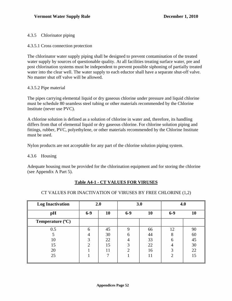
Vermont Water Supply Rule December 1, 2010
Appendices Page 52
4.3.5 Chlorinator piping 4.3.5.1 Cross connection protection The chlorinator water supply piping shall be designed to prevent contamination of the treated water supply by sources of questionable quality. At all facilities treating surface water, pre and post chlorination systems must be independent to prevent possible siphoning of partially treated water into the clear well. The water supply to each eductor shall have a separate shut-off valve. No master shut off valve will be allowed. 4.3.5.2 Pipe material The pipes carrying elemental liquid or dry gaseous chlorine under pressure and liquid chlorine must be schedule 80 seamless steel tubing or other materials recommended by the Chlorine Institute (never use PVC). A chlorine solution is defined as a solution of chlorine in water and, therefore, its handling differs from that of elemental liquid or dry gaseous chlorine. For chlorine solution piping and fittings, rubber, PVC, polyethylene, or other materials recommended by the Chlorine Institute must be used. Nylon products are not acceptable for any part of the chlorine solution piping system. 4.3.6 Housing Adequate housing must be provided for the chlorination equipment and for storing the chlorine (see Appendix A Part 5).
Table A4-1 - CT VALUES FOR VIRUSES
CT VALUES FOR INACTIVATION OF VIRUSES BY FREE CHLORINE (1,2)
Log Inactivation 2.0 3.0 4.0
pH 6-9 10 6-9 10 6-9 10
Temperature (ºC)
0.5 5 10 15 20 25
6 4 3 2 1 1
45 30 22 15 11 7
9 6 4 3 2 1
66 44 33 22 16 11
12 8 6 4 3 2
90 60 45 30 22 15

Vermont Water Supply Rule December 1, 2010
Appendices Page 53
NOTES: 1. Data adapted from Sobsey (1988) for inactivation of Hepatitis A Virus (HAV) at pH = 6,
7, 8, 9, and 10 and temperature = 5 C. CT values include a safety factor of 3. 2. CT values adjusted to other temperatures by doubling CT for each 10 C drop in
temperature.

Vermont Water Supply Rule December 1, 2010
Appendices Page 54
Table A4-2 - GIARDIA INACTIVATION CT Values for Inactivation of Giardia Cysts by Free Chlorine at 0.5oC or Lower
Chlorine
Concen-
tration
(mg/L)
pH<=6 Log Inactivations
pH=6.5 Log Inactivations
pH=7.0 Log Inactivations
0.5 1.0 1.5 2.0 2.5 3.0 0.5 1.0 1.5 2.0 2.5 3.0 0.5 1.0 1.5 2.0 2.5 3.0<=0.4 23 46 69 91 114 137 27 54 82 109 136 163 33 65 98 130 163 1950.6 24 47 71 94 118 141 28 56 84 112 140 168 33 67 100 133 167 2000.8 24 48 73 97 121 145 29 57 86 115 143 172 34 68 103 137 171 2051 25 49 74 99 123 148 29 59 88 117 147 176 35 70 105 140 175 2101.2 25 51 76 101 127 152 30 60 90 120 150 180 36 72 108 143 179 2151.4 26 52 78 103 129 155 31 61 92 123 153 184 37 74 111 147 184 2211.6 26 52 79 105 131 157 32 63 95 126 158 189 38 75 113 151 188 2261.8 27 54 81 108 135 162 32 64 97 129 161 193 39 77 116 154 193 2312 28 55 83 110 138 165 33 66 99 131 164 197 39 79 118 157 197 2362.2 28 56 85 113 141 169 34 67 101 134 168 201 40 81 121 161 202 2422.4 29 57 86 115 143 172 34 68 103 137 171 205 41 82 124 165 206 2472.6 29 58 88 117 146 175 35 70 105 139 174 209 42 84 126 168 210 2522.8 30 59 89 119 148 178 36 71 107 142 178 213 43 86 129 171 214 2573 30 60 91 121 151 181 36 72 109 145 181 217 44 87 131 174 218 261
Chlorine
Concen-
tration
(mg/L)
pH=7.5 Log Inactivations
pH=8.0 Log Inactivations
pH=8.5 Log Inactivations
0.5 1.0 1.5 2.0 2.5 3.0 0.5 1.0 1.5 2.0 2.5 3.0 0.5 1.0 1.5 2.0 2.5 3.0<=0.4 40 79 119 158 198 237 46 92 139 185 231 277 55 110 165 219 274 3290.6 40 80 120 159 199 239 48 95 143 191 238 286 57 114 171 228 285 3420.8 41 82 123 164 205 246 49 98 148 197 246 295 59 118 177 236 295 3541 42 84 127 169 211 253 51 101 152 203 253 304 61 122 183 243 304 3651.2 43 86 130 173 216 259 52 104 157 209 261 313 63 125 188 251 313 3761.4 44 89 133 177 222 266 54 107 161 214 268 321 65 129 194 258 323 3871.6 46 91 137 182 228 273 55 110 165 219 274 329 66 132 199 265 331 3971.8 47 93 140 186 233 279 56 113 169 225 282 338 68 136 204 271 339 4072 48 95 143 191 238 286 58 115 173 231 288 346 70 139 209 278 348 4172.2 50 99 149 198 248 297 59 118 177 235 294 353 71 142 213 284 355 4262.4 50 99 149 199 248 298 60 120 181 241 301 361 73 145 218 290 363 4352.6 51 101 152 203 253 304 61 123 184 245 307 368 74 148 222 296 370 4442.8 52 103 155 207 258 310 63 125 188 250 313 375 75 151 226 301 377 4523 53 105 158 211 263 316 64 127 191 255 318 382 77 153 230 307 383 460
Chlorine
Concen-
tration
(mg/L)
pH <=9.0 Log Inactivations
Note: CT = CT for 3-Log Inactivation (99.9%)
0.5 1.0 1.5 2.0 2.5 3.0 <=0.4 65 130 195 260 325 390 0.6 68 136 204 271 339 407 0.8 70 141 211 281 352 422 1 73 146 219 291 364 437 1.2 75 150 226 301 376 451 1.4 77 155 232 309 387 464 1.6 80 159 239 318 398 477 1.8 82 163 245 326 408 489 2 83 167 250 333 417 500 2.2 85 170 256 341 426 511 2.4 87 174 261 348 435 522 2.6 89 178 267 355 444 533 2.8 91 181 272 362 453 543 3 92 184 276 368 460 552

Vermont Water Supply Rule December 1, 2010
Appendices Page 55
CT Values for Inactivation of Giardia Cysts by Free Chlorine at 5oC
Chlorine
Concen-
tration
(mg/L)
pH<=6 Log Inactivations
pH=6.5 Log Inactivations
pH=7.0 Log Inactivations
0.5 1.0 1.5 2.0 2.5 3.0 0.5 1.0 1.5 2.0 2.5 3.0 0.5 1.0 1.5 2.0 2.5 3.0<=0.4 16 32 49 65 81 97 20 39 59 78 98 117 23 46 70 93 116 1390.6 17 33 50 67 83 100 20 40 60 80 100 120 24 48 72 95 119 1430.8 17 34 52 69 86 103 20 41 61 81 102 122 24 49 73 97 122 1461 18 35 53 70 88 105 21 42 63 83 104 125 25 50 75 99 124 1491.2 18 36 54 71 89 107 21 42 64 85 106 127 25 51 76 101 127 1521.4 18 36 55 73 91 109 22 43 65 87 108 130 26 52 78 103 129 1551.6 19 37 56 74 93 111 22 44 66 88 110 132 26 53 79 105 132 1581.8 19 38 57 76 95 114 23 45 68 90 113 135 27 54 81 108 135 1622 19 39 58 77 97 116 23 46 69 92 115 138 28 55 83 110 138 1652.2 20 39 59 79 98 118 23 47 70 93 117 140 28 56 85 113 141 1692.4 20 40 60 80 100 120 24 48 72 95 119 143 29 57 86 115 143 1722.6 20 41 61 81 102 122 24 49 73 97 122 146 29 58 88 117 146 1752.8 21 41 62 83 103 124 25 49 74 99 123 148 30 59 89 119 148 1783 21 42 63 84 105 126 25 50 76 101 126 151 30 61 91 121 152 182
Chlorine
Concen-
tration
(mg/L)
pH=7.5 Log Inactivations
pH=8.0 Log Inactivations
pH=8.5 Log Inactivations
0.5 1.0 1.5 2.0 2.5 3.0 0.5 1.0 1.5 2.0 2.5 3.0 0.5 1.0 1.5 2.0 2.5 3.0<=0.4 28 55 83 111 138 166 33 66 99 132 165 198 39 79 118 157 197 2360.6 29 57 86 114 143 171 34 68 102 136 170 204 41 81 122 163 203 2440.8 29 58 88 117 146 175 35 70 105 140 175 210 42 84 126 168 210 2521 30 60 90 119 149 179 36 72 108 144 180 216 43 87 130 173 217 2601.2 31 61 92 122 153 183 37 74 111 147 184 221 45 89 134 178 223 2671.4 31 62 94 125 156 187 38 76 114 151 189 227 46 91 137 183 228 2741.6 32 64 96 128 160 192 39 77 116 155 193 232 47 94 141 187 234 2811.8 33 65 98 131 163 196 40 79 119 159 198 238 48 96 144 191 239 2872 33 67 100 133 167 200 41 81 122 162 203 243 49 98 147 196 245 2942.2 34 68 102 136 170 204 41 83 124 165 207 248 50 100 150 200 250 3002.4 35 70 105 139 174 209 42 84 127 169 211 253 51 102 153 204 255 3062.6 36 71 107 142 178 213 43 86 129 172 215 258 52 104 156 208 260 3122.8 36 72 109 145 181 217 44 88 132 175 219 263 53 106 159 212 265 3183 37 74 111 147 184 221 45 89 134 179 223 268 54 108 162 216 270 324
Chlorine
Concen-
tration
(mg/L)
pH<=9.0 Log Inactivations
Note: CT = CT for 3-Log Inactivation (99.9%)
(mg/L) 0.5 1.0 1.5 2.0 2.5 3.0 <=0.4 47 93 140 186 233 279 0.6 49 97 146 194 243 291 0.8 50 100 151 201 251 301 1 52 104 156 208 260 312 1.2 53 107 160 213 267 320 1.4 55 110 165 219 274 329 1.6 56 112 169 225 281 337 1.8 58 115 173 230 288 345 2 59 118 177 235 294 353 2.2 60 120 181 241 301 361 2.4 61 123 184 245 307 368 2.6 63 125 188 250 313 375 2.8 64 127 191 255 318 382 3 65 130 195 259 324 389
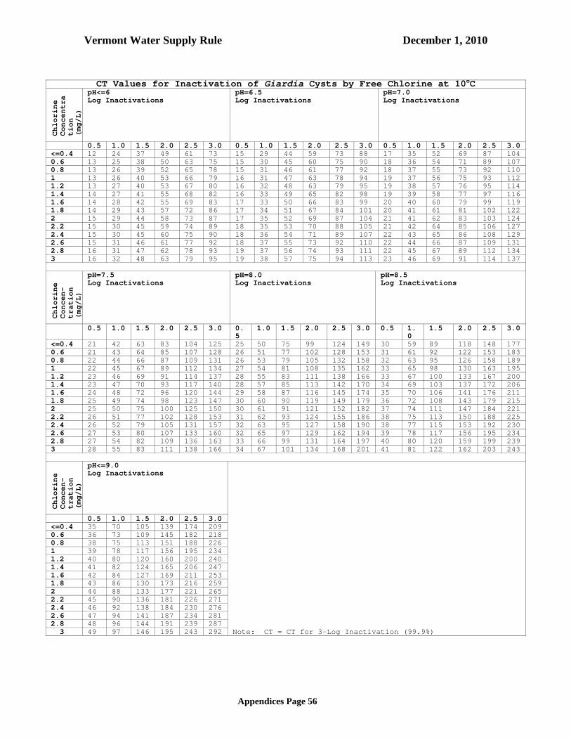
Vermont Water Supply Rule December 1, 2010
Appendices Page 56
CT Values for Inactivation of Giardia Cysts by Free Chlorine at 10oC
Chlorine
Concentra
tion
(mg/L)
pH<=6 Log Inactivations
pH=6.5 Log Inactivations
pH=7.0 Log Inactivations
0.5 1.0 1.5 2.0 2.5 3.0 0.5 1.0 1.5 2.0 2.5 3.0 0.5 1.0 1.5 2.0 2.5 3.0<=0.4 12 24 37 49 61 73 15 29 44 59 73 88 17 35 52 69 87 1040.6 13 25 38 50 63 75 15 30 45 60 75 90 18 36 54 71 89 1070.8 13 26 39 52 65 78 15 31 46 61 77 92 18 37 55 73 92 1101 13 26 40 53 66 79 16 31 47 63 78 94 19 37 56 75 93 1121.2 13 27 40 53 67 80 16 32 48 63 79 95 19 38 57 76 95 1141.4 14 27 41 55 68 82 16 33 49 65 82 98 19 39 58 77 97 1161.6 14 28 42 55 69 83 17 33 50 66 83 99 20 40 60 79 99 1191.8 14 29 43 57 72 86 17 34 51 67 84 101 20 41 61 81 102 1222 15 29 44 58 73 87 17 35 52 69 87 104 21 41 62 83 103 1242.2 15 30 45 59 74 89 18 35 53 70 88 105 21 42 64 85 106 1272.4 15 30 45 60 75 90 18 36 54 71 89 107 22 43 65 86 108 1292.6 15 31 46 61 77 92 18 37 55 73 92 110 22 44 66 87 109 1312.8 16 31 47 62 78 93 19 37 56 74 93 111 22 45 67 89 112 1343 16 32 48 63 79 95 19 38 57 75 94 113 23 46 69 91 114 137
Chlorine
Concen-
tration
(mg/L)
pH=7.5 Log Inactivations
pH=8.0 Log Inactivations
pH=8.5 Log Inactivations
0.5 1.0 1.5 2.0 2.5 3.0 0.5
1.0 1.5 2.0 2.5 3.0 0.5 1.0
1.5 2.0 2.5 3.0
<=0.4 21 42 63 83 104 125 25 50 75 99 124 149 30 59 89 118 148 1770.6 21 43 64 85 107 128 26 51 77 102 128 153 31 61 92 122 153 1830.8 22 44 66 87 109 131 26 53 79 105 132 158 32 63 95 126 158 1891 22 45 67 89 112 134 27 54 81 108 135 162 33 65 98 130 163 1951.2 23 46 69 91 114 137 28 55 83 111 138 166 33 67 100 133 167 2001.4 23 47 70 93 117 140 28 57 85 113 142 170 34 69 103 137 172 2061.6 24 48 72 96 120 144 29 58 87 116 145 174 35 70 106 141 176 2111.8 25 49 74 98 123 147 30 60 90 119 149 179 36 72 108 143 179 2152 25 50 75 100 125 150 30 61 91 121 152 182 37 74 111 147 184 2212.2 26 51 77 102 128 153 31 62 93 124 155 186 38 75 113 150 188 2252.4 26 52 79 105 131 157 32 63 95 127 158 190 38 77 115 153 192 2302.6 27 53 80 107 133 160 32 65 97 129 162 194 39 78 117 156 195 2342.8 27 54 82 109 136 163 33 66 99 131 164 197 40 80 120 159 199 2393 28 55 83 111 138 166 34 67 101 134 168 201 41 81 122 162 203 243
Chlorine
Concen-
tration
(mg/L)
pH<=9.0 Log Inactivations
Note: CT = CT for 3-Log Inactivation (99.9%)
0.5 1.0 1.5 2.0 2.5 3.0 <=0.4 35 70 105 139 174 209 0.6 36 73 109 145 182 218 0.8 38 75 113 151 188 226 1 39 78 117 156 195 234 1.2 40 80 120 160 200 240 1.4 41 82 124 165 206 247 1.6 42 84 127 169 211 253 1.8 43 86 130 173 216 259 2 44 88 133 177 221 265 2.2 45 90 136 181 226 271 2.4 46 92 138 184 230 276 2.6 47 94 141 187 234 281 2.8 48 96 144 191 239 287 3 49 97 146 195 243 292

Vermont Water Supply Rule December 1, 2010
Appendices Page 57
CT Values for Inactivation of Giardia Cysts by Free Chlorine at 15oC
Chlorine
Concen-
tration
(mg/L)
pH<=6 Log Inactivations
pH=6.5 Log Inactivations
pH=7.0 Log Inactivations
0.5 1.0 1.5 2.0 2.5 3.0 0.5 1.0 1.5 2.0 2.5 3.0 0.5 1.0 1.5 2.0 2.5 3.0<=0.4 8 16 25 33 41 49 10 20 30 39 49 59 12 23 35 47 58 700.6 8 17 25 33 42 50 10 20 30 40 50 60 12 24 36 48 60 720.8 9 17 26 35 43 52 10 20 31 41 51 61 12 24 37 49 61 731 9 18 27 35 44 53 11 21 32 42 53 63 13 25 38 50 63 751.2 9 18 27 36 45 54 11 21 32 43 53 64 13 25 38 51 63 761.4 9 18 28 37 46 55 11 22 33 43 54 65 13 26 39 52 65 781.6 9 19 28 37 47 56 11 22 33 44 55 66 13 26 40 53 66 791.8 10 19 29 38 48 57 11 23 34 45 57 68 14 27 41 54 68 812 10 19 29 39 48 58 12 23 35 46 58 69 14 28 42 55 69 832.2 10 20 30 39 49 59 12 23 35 47 58 70 14 28 43 57 71 852.4 10 20 30 40 50 60 12 24 36 48 60 72 14 29 43 57 72 862.6 10 20 31 41 51 61 12 24 37 49 61 73 15 29 44 59 73 882.8 10 21 31 41 52 62 12 25 37 49 62 74 15 30 45 59 74 893 11 21 32 42 53 63 13 25 38 51 63 76 15 30 46 61 76 91
Chlorine
Concen-
tration
(mg/L)
pH=7.5 Log Inactivations
pH=8.0 Log Inactivations
pH=8.5 Log Inactivations
0.5 1.0 1.5 2.0 2.5 3.0 0.5 1.0 1.5 2.0 2.5 3.0 0.5 1.0 1.5 2.0 2.5 3.0<=0.4 14 28 42 55 69 83 17 33 50 66 83 99 20 39 59 79 98 1180.6 14 29 43 57 72 86 17 34 51 68 85 102 20 41 61 81 102 1220.8 15 29 44 59 73 88 18 35 53 70 88 105 21 42 63 84 105 1261 15 30 45 60 75 90 18 36 54 72 90 108 22 43 65 87 108 1301.2 15 31 46 61 77 92 19 37 56 74 93 111 22 45 67 89 112 1341.4 16 31 47 63 78 94 19 38 57 76 95 114 23 46 69 91 114 1371.6 16 32 48 64 80 96 19 39 58 77 97 116 24 47 71 94 118 1411.8 16 33 49 65 82 98 20 40 60 79 99 119 24 48 72 96 120 1442 17 33 50 67 83 100 20 41 61 81 102 122 25 49 74 98 123 1472.2 17 34 51 68 85 102 21 41 62 83 103 124 25 50 75 100 125 1502.4 18 35 53 70 88 105 21 42 64 85 106 127 26 51 77 102 128 1532.6 18 36 54 71 89 107 22 43 65 86 108 129 26 52 78 104 130 1562.8 18 36 55 73 91 109 22 44 66 88 110 132 27 53 80 106 133 1593 19 37 56 74 93 111 22 45 67 89 112 134 27 54 81 108 135 162
Chlorine
Concen-
tration
(mg/L)
pH<=9.0 Log Inactivations
Note: CT = CT for 3-Log Inactivation (99.9%)
0.5 1.0 1.5 2.0 2.5 3.0 <=0.4 23 47 70 93 117 140 0.6 24 49 73 97 122 146 0.8 25 50 76 101 126 151 1 26 52 78 104 130 156 1.2 27 53 80 107 133 160 1.4 28 55 83 110 138 165 1.6 28 56 85 113 141 169 1.8 29 58 87 115 144 173 2 30 59 89 118 148 177 2.2 30 60 91 121 151 181 2.4 31 61 92 123 153 184 2.6 31 63 94 125 157 188 2.8 32 64 96 127 159 191 3 33 65 98 130 163 195

Vermont Water Supply Rule December 1, 2010
Appendices Page 58
CT Values for Inactivation of Giardia Cysts by Free Chlorine at 20oC
Chlorine
Concen-
tration
(mg/L)
pH<=6 Log Inactivations
pH=6.5 Log Inactivations
ph=7.0 Log Inactivations
0.5 1.0 1.5 2.0 2.5 3.0 0.5 1.0 1.5 2.0 2.5 3.0 0.5 1.0 1.5 2.0 2.5 3.0<=0.4 6 12 18 24 30 36 7 15 22 29 37 44 9 17 26 35 43 520.6 6 13 19 25 32 38 8 15 23 30 38 45 9 18 27 36 45 540.8 7 13 20 26 33 39 8 15 23 31 38 46 9 18 28 37 46 551 7 13 20 26 33 39 8 16 24 31 39 47 9 19 28 37 47 561.2 7 13 20 27 33 40 8 16 24 32 40 48 10 19 29 38 48 571.4 7 14 21 27 34 41 8 16 25 33 41 49 10 19 29 39 48 581.6 7 14 21 28 35 42 8 17 25 33 42 50 10 20 30 39 49 591.8 7 14 22 29 36 43 9 17 26 34 43 51 10 20 31 41 51 612 7 15 22 29 37 44 9 17 26 35 43 52 10 21 31 41 52 622.2 7 15 22 29 37 44 9 18 27 35 44 53 11 21 32 42 53 632.4 8 15 23 30 38 45 9 18 27 36 45 54 11 22 33 43 54 652.6 8 15 23 31 38 46 9 18 28 37 46 55 11 22 33 44 55 662.8 8 16 24 31 39 47 9 19 28 37 47 56 11 22 34 45 56 673 8 16 24 31 39 47 10 19 29 38 48 57 11 23 34 45 57 68
Chlorine
Concen-
tration
(mg/L)
pH=7.5 Log Inactivations
pH=8.0 Log Inactivations
pH=8.5 Log Inactivations
0.5 1.0 1.5 2.0 2.5 3.0 0.5 1.0 1.5 2.0 2.5 3.0 0.5 1.0 1.5 2.0 2.5 3.0<=0.4 10 21 31 41 52 62 12 25 37 49 62 74 15 30 45 59 74 890.6 11 21 32 43 53 64 13 26 39 51 64 77 15 31 46 61 77 920.8 11 22 33 44 55 66 13 26 40 53 66 79 16 32 48 63 79 951 11 22 34 45 56 67 14 27 41 54 68 81 16 33 49 65 82 981.2 12 23 35 46 58 69 14 28 42 55 69 83 17 33 50 67 83 1001.4 12 23 35 47 58 70 14 28 43 57 71 85 17 34 52 69 86 1031.6 12 24 36 48 60 72 15 29 44 58 73 87 18 35 53 70 88 1051.8 12 25 37 49 62 74 15 30 45 59 74 89 18 36 54 72 90 1082 13 25 38 50 63 75 15 30 46 61 76 91 18 37 55 73 92 1102.2 13 26 39 51 64 77 16 31 47 62 78 93 19 38 57 75 94 1132.4 13 26 39 52 65 78 16 32 48 63 79 95 19 38 58 77 96 1152.6 13 27 40 53 67 80 16 32 49 65 81 97 20 39 59 78 98 1172.8 14 27 41 54 68 81 17 33 50 66 83 99 20 40 60 79 99 1193 14 28 42 55 69 83 17 34 51 67 84 101 20 41 61 81 102 122
Chlorine
Concen-
tration
(mg/L)
pH<=9.0 Log Inactivations
Note: CT = CT for 3-Log Inactivation (99.9%)
0.5 1.0 1.5 2.0 2.5 3.0 <=0.4 18 35 53 70 88 105 0.6 18 36 55 73 91 109 0.8 19 38 57 75 94 113 1 20 39 59 78 98 117 1.2 20 40 60 80 100 120 1.4 21 41 62 82 103 123 1.6 21 42 63 84 105 126 1.8 22 43 65 86 108 129 2 22 44 66 88 110 132 2.2 23 45 68 90 113 135 2.4 23 46 69 92 115 138 2.6 24 47 71 94 118 141 2.8 24 48 72 95 119 143 3 24 49 73 97 122 146

Vermont Water Supply Rule December 1, 2010
Appendices Page 59
CT Values for Inactivation of Giardia Cysts by Free Chlorine at 25oC
Chlorine
Concen-
tration
(mg/L)
pH<=6 Log Inactivations
pH=6.5 Log Inactivations
pH=7.0 Log Inactivations
0.5 1.0 1.5 2.0 2.5 3.0 0.5 1.0 1.5 2.0 2.5 3.0 0.5 1.0 1.5 2.0 2.5 3.0<=0.4 4 8 12 16 20 24 5 10 15 19 24 29 6 12 18 23 29 350.6 4 8 13 17 21 25 5 10 15 20 25 30 6 12 18 24 30 360.8 4 9 13 17 22 26 5 10 16 21 26 31 6 12 19 25 31 371 4 9 13 17 22 26 5 10 16 21 26 31 6 12 19 25 31 371.2 5 9 14 18 23 27 5 11 16 21 27 32 6 13 19 25 32 381.4 5 9 14 18 23 27 6 11 17 22 28 33 7 13 20 26 33 391.6 5 9 14 19 23 28 6 11 17 22 28 33 7 13 20 27 33 401.8 5 10 15 19 24 29 6 11 17 23 28 34 7 14 21 27 34 412 5 10 15 19 24 29 6 12 18 23 29 35 7 14 21 27 34 412.2 5 10 15 20 25 30 6 12 18 23 29 35 7 14 21 28 35 422.4 5 10 15 20 25 30 6 12 18 24 30 36 7 14 22 29 36 432.6 5 10 16 21 26 31 6 12 19 25 31 37 7 15 22 29 37 442.8 5 10 16 21 26 31 6 12 19 25 31 37 8 15 23 30 38 453 5 11 16 21 27 32 6 13 19 25 32 38 8 15 23 31 38 46
Chlorine
Concen-
tration
(mg/L)
pH=7.5 Log Inactivations
pH=8.0 Log Inactivations
pH=8.5 Log Inactivations
(mg/L) 0.5 1.0 1.5 2.0 2.5 3.0 0.5 1.0 1.5 2.0 2.5 3.0 0.5 1.0 1.5 2.0 2.5 3.0<=0.4 7 14 21 28 35 42 8 17 25 33 42 50 10 20 30 39 49 590.6 7 14 22 29 36 43 9 17 26 34 43 51 10 20 31 41 51 610.8 7 15 22 29 37 44 9 18 27 35 44 53 11 21 32 42 53 631 8 15 23 30 38 45 9 18 27 36 45 54 11 22 33 43 54 651.2 8 15 23 31 38 46 9 18 28 37 46 55 11 22 34 45 56 671.4 8 16 24 31 39 47 10 19 29 38 48 57 12 23 35 46 58 691.6 8 16 24 32 40 48 10 19 29 39 48 58 12 23 35 47 58 701.8 8 16 25 33 41 49 10 20 30 40 50 60 12 24 36 48 60 722 8 17 25 33 42 50 10 20 31 41 51 61 12 25 37 49 62 742.2 9 17 26 34 43 51 10 21 31 41 52 62 13 25 38 50 63 752.4 9 17 26 35 43 52 11 21 32 42 53 63 13 26 39 51 64 772.6 9 18 27 35 44 93 11 22 33 43 54 65 13 26 39 52 65 782.8 9 18 27 36 45 54 11 22 33 44 55 66 13 27 40 53 67 803 9 18 28 37 46 55 11 22 34 45 56 67 14 27 41 54 68 81
Chlorine
Concen-
tration
(mg/L)
pH<=9.0 Log Inactivations
Note: CT = CT for 3-Log Inactivation (99.9%)
(mg/L) 0.5 1.0 1.5 2.0 2.5 3.0 <=0.4 12 23 35 47 58 70 0.6 12 24 37 49 61 73 0.8 13 25 38 50 63 75 1 13 26 39 52 65 78 1.2 13 27 40 53 67 80 1.4 14 27 41 55 68 82 1.6 14 28 42 56 70 84 1.8 14 29 43 57 72 86 2 15 29 44 59 73 88 2.2 15 30 45 60 75 90 2.4 15 31 46 61 77 92 2.6 16 31 47 63 78 94 2.8 16 32 48 64 80 96 3 16 32 49 65 81 97
4.3.7 Non-Chorine Based Disinfection

Vermont Water Supply Rule December 1, 2010
Appendices Page 60
Design and installation of disinfection methods other than chlorine based systems, such as ultraviolet light, may be permitted, provided such designs conform to the Secretary’s written guidelines. 4.4 Softening The softening process selected shall be based upon the mineral qualities of the raw water and the desired finished water quality in conjunction with requirements for disposal of sludge or brine waste, cost of plant, cost of chemicals and plant location. Applicability of the process chosen shall be demonstrated. 4.4.1 Lime or lime-soda process Design standards for rapid mix, flocculation and sedimentation are in Appendix A Subpart 4.1. Additional consideration shall be given to the following process elements. 4.4.1.1 Hydraulics When split treatment is used, the bypass line should be sized to carry total plant flow, and an accurate means of measuring and splitting the flow shall be provided. 4.4.1.2 Aeration Determinations should be made for the carbon dioxide content of the raw water. When concentrations exceed 10 milligrams per liter, the economics of removal by aeration as opposed to removal with lime should be considered if it has been determined that dissolved oxygen in the finished water will not cause corrosion problems in the distribution system. 4.4.1.3 Chemical feed point Lime and recycled sludge should be fed directly into the rapid mix basin. 4.4.1.4 Rapid mix Rapid mix basins shall not exceed 30 seconds detention time with adequate velocity gradients to keep the lime particles dispersed. 4.4.1.5 Stabilization Equipment for stabilization of water softened by the lime or lime-soda process is required. (see Appendix A Subpart 4.7). 4.4.1.6 Sludge Collection (a) Mechanical sludge removal equipment shall be provided in the sedimentation basin. (b) Sludge recycling to the rapid mix should be provided.

Vermont Water Supply Rule December 1, 2010
Appendices Page 61
4.4.1.7 Sludge Disposal Provisions shall be included for proper disposal of softening sludge. (see Appendix A Subpart 4.10). 4.4.1.8 Disinfection The use of excess lime shall not be considered an acceptable substitute for disinfection. 4.4.1.9 Plant start-up The plant processes shall be manually started following shut-down. 4.4.2 Cation exchange process Alternative methods of hardness reduction should be investigated when the sodium content and dissolved solids concentration is of concern. 4.4.2.1 Pre-treatment requirements Iron, manganese, or a combination of the two, should not exceed 0.3 milligrams per liter in the water as applied to the ion exchange resin. Pre-treatment is required when the content of iron, manganese, or a combination of the two, is one milligram per liter or more. (see Appendix A Subpart 4.5). Waters having 5 units or more turbidity should not be applied directly to the cation exchange softener. 4.4.2.2 Design The units may be of pressure or gravity type, of either an upflow or downflow design. Automatic regeneration based on volume of water softened should be used unless manual regeneration is justified and is approved by the reviewing authority. A manual override shall be provided on all automatic controls. 4.4.2.3 Exchange capacity The design capacity for hardness removal should not exceed 20,000 grains per cubic foot when resin is regenerated with 0.3 pounds of salt per kilograin of hardness removed. 4.4.2.4 Depth of resin The depth of the exchange resin should not be less than three feet. 4.4.2.5 Flow rates

Vermont Water Supply Rule December 1, 2010
Appendices Page 62
The rate of softening should not exceed seven gallons per minute per square foot of bed area and the backwash rate should be six to eight gallons per minute per square foot of bed area. Rate-of-flow controllers or the equivalent shall be installed for the above purposes. 4.4.2.6 Freeboard The freeboard will depend upon the specific gravity of the resin and the direction of water flow. Generally, the washwater collector should be 24 inches above the top of the resin on downflow units. 4.4.2.7 Underdrains and supporting gravel The bottoms, strainer systems and support for the exchange resin shall conform to criteria provided for rapid rate gravity filters. (see Appendix A Subparts 4.2.4.5 and 4.2.4.7). 4.4.2.8 Brine distribution Facilities should be included for even distribution of the brine over the entire surface of both upflow and downflow units. 4.4.2.9 Cross-connection control Backwash, rinse and air relief discharge pipes should be installed in such a manner as to prevent any possibility of back-siphonage. 4.4.2.10 Bypass piping and equipment A bypass shall be provided around softening units to produce a blended water of desirable hardness. Totalizing meters shall be installed on the bypass line and on each softener unit. The bypass line shall have a shutoff valve and should have an automatic proportioning or regulating device. In some installations, it may be necessary to treat the bypassed water to obtain acceptable levels of iron and/or manganese in the finished water.
4.4.2.11 Additional limitations Silica gel resins should not be used for waters having a pH above 8.4 or containing less than six milligrams per liter silica and should not be used when iron is present. When the applied water contains a chlorine residual, the cation exchange resin shall be a type that is not damaged by residual chlorine. Phenolic resin should not be used. 4.4.2.12 Sampling taps Smooth-nose sampling taps shall be provided for the collection of representative samples. The taps shall be located to provide for sampling of the softener influent, effluent and blended water. The sampling taps for the blended water shall be at least 20 feet downstream from the point of

Vermont Water Supply Rule December 1, 2010
Appendices Page 63
blending. Petcocks are not acceptable as sampling taps. Sampling taps should be provided on the brine tank discharge piping. 4.4.2.13 Brine and salt storage tanks (a) Salt dissolving or brine tanks and wet salt storage tanks shall be covered and be
corrosion-resistant. (b) The make-up water inlet shall be protected from back-siphonage. Water for filling the
tank should be distributed over the entire surface by pipes above the maximum brine level in the tank. The tanks should be provided with an automatic declining level control system on the make-up water line.
(c) Wet salt storage basins shall be equipped with manholes or hatchways for access and for
direct dumping of salt from a truck. Openings shall be provided with raised curbs and watertight covers having overlapping edges similar to those required for finished water reservoirs.
(d) Overflows, where provided, shall be protected with corrosion resistant screens and shall
terminate with either a turned downed bend having a proper free fall discharge or a self-closing flap valve.
(e) Two wet salt storage tanks or compartments designed to operate independently should be
provided. (f) The salt shall be supported on graduated layers of gravel placed over a brine collection
system. (g) Alternative designs which are conducive to frequent cleaning of the wet salt storage tank
may be considered. 4.4.2.14 Salt and brine storage capacity Total salt storage should have sufficient capacity to provide for at least 30 days of operation. 4.4.2.15 Brine pump or eductor An eductor may be used to transfer brine from the brine tank to the softeners. If a pump is used, a brine measuring tank or means of metering should be provided to obtain proper dilution. 4.4.2.16 Stabilization Stabilization for corrosion control shall be provided. An alkali feeder shall be provided except when exempted by the reviewing authority. 4.4.2.17 Waste disposal

Vermont Water Supply Rule December 1, 2010
Appendices Page 64
Suitable disposal shall be provided for brine waste (See Appendix A Subpart 4.10). Where the volume of spent brine must be reduced, consideration may be given to using a part of the spent brine for a subsequent regeneration. 4.4.2.18 Construction materials Pipes and contact materials shall be resistant to the aggressiveness of salt. Plastic and red brass are acceptable piping materials. Steel and concrete shall be coated with a non-leaching protective coating which is compatible with salt and brine. 4.4.2.19 Housing Bagged salt and dry bulk salt storage shall be enclosed and separated from other operating areas in order to prevent damage to equipment. 4.5 Iron & Manganese Control Iron and manganese control, as used herein, refers solely to treatment processes designed specifically for this purpose. The treatment process used will depend upon the character of the raw water. The selection of one or more treatment processes must meet specific local conditions as determined by engineering investigations, including chemical analyses of representative samples of water to be treated, and receive the approval of the Secretary. It may be necessary to operate a pilot plant in order to gather all information pertinent to the design. Consideration should be given to adjusting pH of the raw water to optimize reaction. 4.5.1 Removal by oxidation, detention and filtration 4.5.1.1 Oxidation may be by aeration or by chemical oxidation with chlorine, potassium
permanganate, ozone or chlorine dioxide. 4.5.1.2 Detention (a) Reaction - A minimum detention time of 20 minutes shall be provided following aeration
to insure that the oxidation reactions are as complete as possible. This minimum detention may be omitted only where a pilot plant study indicates no need for detention. The detention basin should be designed as a holding tank with no provisions for sludge collection but with sufficient baffling to prevent short circuiting.
(b) Sedimentation - Sedimentation basins are recommended when treating water with high
iron and/or manganese content, or where chemical coagulation is used to reduce the load on the filters. Provisions for sludge removal shall be made.
4.5.1.3 Filtration Filters shall be provided and shall conform to Subpart 4.2.

Vermont Water Supply Rule December 1, 2010
Appendices Page 65
4.5.2 Removal by manganese greensand filtration This process consists of either a continuous feed of potassium permanganate to the influent of a manganese greensand filter or regeneration of filter media by permanganate. a) Provisions should be made to apply the permanganate as far ahead of the filter as
practical and to a point immediately before the filter. b) Other oxidizing agents or processes such as chlorination or aeration may be used prior to
the permanganate feed to reduce the cost of the chemical. c) Anthracite media cap of at least six inches over manganese greensand is recommended. d) Normal filtration rate is three to five gallons per minute per square foot. e) Normal wash rate is 8 to 10 gallons per minute per square foot. f) Air washing should be provided. g) Sample taps shall be provided:
(1) prior to application of permanganate, (2) immediately ahead of filtration, (3) at the filter effluent.
4.5.3 Removal by ion exchange This process of iron and manganese removal should not be used for water containing more than 0.3 milligrams per liter of iron, manganese or combination thereof. This process is not acceptable where either the raw water or wash water contains dissolved oxygen. 4.5.4 Sequestration by polyphosphates Sequestration process will only be considered as a viable option for use in Vermont under the following conditions: (a) Pilot work done with specific sequestering agent being proposed demonstrating
effectiveness under various conditions i.e. time, temperature, pH. (b) Specific program presented for operational control and monitoring of sequestering agent
and its continued effectiveness. (c) Iron, manganese or combination thereof shall not be in excess of 1.0 mg/l. (d) The maximum concentration of phosphate applied shall not exceed 10 ppm PO4. (e) Feeding equipment shall conform to the requirements of Appendix A Subpart 5. (f) Stock phosphate solution must be kept covered and disinfected by maintaining
approximately 10 mg/l free chlorine residual. Newer premixed phosphate solutions may not require free chlorine residual be maintained.
(g) Polyphosphates shall not be applied ahead of iron and manganese removal treatment. The point of application shall be prior to any aeration, oxidation or disinfection if no iron or manganese removal treatment is provided.
(h) Phosphate chemicals must meet NSF Drinking Water Treatment Chemicals and System Components Certification.
(i) Testing equipment for phosphates must be available to allow daily monitoring of sequestering chemical levels in the distribution system.

Vermont Water Supply Rule December 1, 2010
Appendices Page 66
4.5.5 Sampling equipment Taps shall be located on each raw water source, each treatment unit influent and each treatment unit effluent. 4.5.6 Testing equipment Testing equipment should be provided for all plants. The equipment should have the capacity to accurately measure the iron content to a minimum detection level of 0.1 milligrams per liter and the manganese content to a minimum detection level of 0.03 milligrams per liter. 4.6 Fluoridation Sodium fluoride, sodium silicofluoride and hydrofluorosilicic acid shall conform to the NSF Drinking Water Treatment Chemicals and System Components Certification. The proposed method of fluoride feed must be approved by the Secretary prior to preparation of final plans and specifications. The proposed method will conform to CDC Water Fluoridation: A Manual for Engineers and Technicians, latest edition. 4.6.1 Fluoride compound storage Fluoride chemicals should be isolated from other chemicals to prevent contamination. Compounds shall be stored in covered or unopened shipping containers and should be stored inside a building. Unsealed storage units for hydrofluorosilicic acid must be vented to the atmosphere at a point outside any building. Bags, fiber drums and steel drums should be stored on pallets. 4.6.2 Chemical feed equipment and methods In addition to the requirements in Appendix A Part 5, fluoride feed equipment shall meet the following requirements: (a) scales, loss-of-weight recorders, water meters or liquid level indicators, as appropriate,
accurate to within five percent of the average daily change in reading shall be provided for chemical feeds;
(b) feeders shall be accurate to within five percent of any desired feed rate; (c) the point of application of hydrofluorosilicic acid, if into a horizontal pipe, shall be in the
lower half of the pipe; (d) a fluoride solution, including hydrofluorosilicic acid, shall be applied by a positive
displacement pump; (e) anti-siphon devices shall be provided for all fluoride feed lines and dilution water lines; (f) a device to measure the flow of water to be treated is required; (g) the dilution water pipe shall terminate at least two pipe diameters above the solution tank
when an upflow saturator is not used; (h) water used for sodium fluoride dissolution shall be softened if hardness exceeds 75 mg/l
as calcium carbonate;

Vermont Water Supply Rule December 1, 2010
Appendices Page 67
(i) fluoride solutions shall not be injected to a point of negative pressure; (j) the electrical outlet used for the fluoride feed pump should have a nonstandard receptacle
and shall be electrically interconnected with the well or service pump; and (k) sodium fluoride saturators should be of the upflow type and be provided with a meter and
backflow protection on the makeup water line. 4.6.4 Protective equipment Protective equipment, as outlined in Appendix A Subpart 5.3.4, and as required by OSHA and VOSHA regulations, shall be provided for operators handling fluoride compounds. 4.6.5 Dust control (a) Provision must be made for the transfer of dry fluoride compounds from shipping
containers to storage bins or hoppers in such a way as to minimize the quantity of fluoride dust which may enter the room in which the equipment is installed. The enclosure shall be provided with an exhaust fan and dust filter which place the hopper under a negative pressure. Air exhausted from fluoride handling equipment shall discharge through a dust filter to the outside atmosphere of the building.
(b) Provision shall be made for disposing of empty bags, drums or barrels in a manner which will minimize exposure to fluoride dusts. A floor drain should be provided to facilitate the hosing of floors. A floor drain may require a discharge permit from the Secretary.
4.6.6 Testing equipment Equipment shall be provided for measuring the quantity of fluoride in the water. Such equipment shall be subject to the approval of the Secretary. 4.7 Stabilization Water that is unstable due to natural causes or to subsequent treatment should be stabilized. 4.7.1 Polyphosphates The feeding of polyphosphates may be applicable for corrosion control. (a) Feed equipment shall conform to Appendix A Part 5, Chemical Application. (b) Phosphate must meet NSF Drinking water treatment chemicals and system components
certification. (c) Stock phosphate solution must be kept covered and disinfected by carrying
approximately 10 milligrams per liter free chlorine residual. (d) Satisfactory chlorine residuals shall be maintained in the distribution system when
phosphates are used. 4.7.2 Other treatment

Vermont Water Supply Rule December 1, 2010
Appendices Page 68
Other treatment for controlling corrosive waters by the use of sodium silicate and sodium bicarbonate shall be used where necessary. Any proprietary compound must receive the specific approval of the Secretary before use. Chemical feeders shall be as required in Appendix A Part 5. 4.7.3 Water unstable due to biochemical action in distribution system Unstable water resulting from the bacterial decomposition of organic matter in water (especially in dead end mains), the biochemical action within tubercles, and the reduction of sulfates to sulfides should be prevented by the maintenance of a free chlorine residual throughout the distribution system. 4.8 Taste & Odor Control Provision shall be made for the control of taste and odor as required by the Secretary. Chemicals shall be added sufficiently ahead of other treatment processes to assure adequate contact time for an effective and economical use of the chemicals. Where severe taste and odor problems are encountered in-plant and/or pilot plant studies are required. 4.8.1 Flexibility Treatment plants that supply water with known taste and odor problems should have equipment available to treat these problems. The equipment should have several control processes available for treatment flexibility in addressing the problem. 4.8.2 Chlorination Chlorination can be used for the removal of some objectionable odors. Adequate contact time must be provided to complete the chemical reactions involved. Excessive potential trihalomethane production through this process should be avoided by adequate bench-scale testing prior to design. The breakpoint technique of chlorinating is recommended. 4.8.3 Chlorine dioxide Chlorine dioxide has been generally recognized as a treatment for tastes caused by industrial wastes, such as phenols. However, chlorine dioxide can be used in the treatment of any taste and odor that is treatable by an oxidizing compound. Provisions shall be made for proper storing and handling of the sodium chlorite, so as to eliminate any danger of explosion. 4.8.4 Powdered activated carbon (a) Powdered activated carbon when prescribed should be added as early as possible in the
treatment process to provide maximum contact time. Flexibility to allow the addition of carbon at several points is preferred. Activated carbon should not be applied near the point of chlorine application.

Vermont Water Supply Rule December 1, 2010
Appendices Page 69
(b) The carbon can be added as a premixed slurry or by means of a dry feed machine as long as the carbon is properly wetted.
(c) Continuous agitation or resuspension equipment is necessary to keep the carbon from depositing in the slurry storage tank.
(d) Provision shall be made for adequate dust and explosion control. (e) The required rate of feed of carbon in a water treatment plant depends upon the tastes
and/or odors involved, but provision should be made for adding from 0.1 milligrams per liter to at least 40 milligrams per liter.
(f) Powdered activated carbon shall be handled as a potentially combustible material. It should be stored in a building or compartment as nearly fireproof as possible. Other chemicals should not be stored in the same compartment. Carbon feeder rooms should be equipped with explosion-proof electrical outlets, lights and motors.
4.8.5 Granular activated carbon adsorption units See Subpart 4.2.1.6 of this appendix. 4.8.6 Copper sulphate and other copper compounds Continuous or periodic treatment of water with copper compounds to kill algae or other growths shall be controlled to prevent copper in excess of 1.3 milligrams per liter as copper in the plant effluent or distribution system. Care shall be taken to assure an even distribution. A permit shall be obtained from the Secretary prior to any such treatment. (See 10 V.S.A., § 1263(a)) 4.8.7 Aeration See Appendix A Subpart 4.4. 4.8.8 Potassium permanganate Application of potassium permanganate may be considered, providing the treatment shall be designed so that the products of the reaction are not visible in the finished water. 4.8.9 Ozone Ozonation can be used as a means of taste and odor control. Adequate contact time must be provided to complete the chemical reactions involved. Ozone is generally more desirable for treating water with high threshold odors. 4.8.10 Other Methods The decision to use any other methods of taste and odor control should be made only after careful laboratory and/or pilot plant tests and on consultation with the Secretary. 4.9 Microscreening

Vermont Water Supply Rule December 1, 2010
Appendices Page 70
A microscreen is a mechanical supplement of treatment capable of removing some of the suspended matter from the water by straining. It may be used to reduce nuisance organisms, leaves, weeds and organic matter. It shall not be used in place of: (a) filtration, when filtration is necessary to provide a satisfactory water, or (b) coagulation, in the preparation of water for filtration. 4.9.1 Design (a) Design shall give due consideration to:
(1) nature of the suspended matter to be removed (2) corrosiveness of the water (3) effect of chlorination, when required as a pretreatment (4) duplication of units for continuous operation during equipment maintenance
(b) Design shall provide: (1) a durable, corrosion-resistant screen (2) by-pass arrangements (3) protection against back-siphonage when potable water is used for washing (4) proper disposal of wash waters (see Appendix A Subpart 4.10).
4.10 Waste Handling & Disposal Provisions must be made for proper disposal of water treatment plant waste such as sanitary, laboratory, clarification sludge, iron sludge, filter backwash water, and brine. All waste discharges shall be permitted by the Secretary. In locating waste disposal facilities, due consideration shall be given to preventing potential contamination of the water supply and groundwater. The Department of Environmental Conservation’s Permit Specialists should be contacted (see Rule Introduction) for assistance with regulatory jurisdiction with sludge disposal. Alternative methods of water treatment and chemical use should be considered as a means of reducing waste handling and disposal problems. 4.10.1 Sanitary waste The sanitary waste from water treatment plants, pumping stations, etc., must receive treatment. Waste from these facilities must be discharged directly to a sanitary sewer system, when feasible, or to an on-site waste treatment facility approved by the Secretary. 4.10.2 Alum sludge Lagooning may be used as a method of handling alum sludge. Lagoon size can be calculated using total chemicals used plus a factor for turbidity. Mechanical concentration may be considered. A pilot plant study is required before the design of a mechanical dewatering installation. Freezing changes the nature of alum sludge so that it can be used for fill. Alum sludge can be discharged to a sanitary sewer. However, approval of this method will depend on

Vermont Water Supply Rule December 1, 2010
Appendices Page 71
obtaining approval from the owner of the sewerage system as well as from the Secretary before final designs are made. Lagoons should be designed to produce an effluent satisfactory to the Secretary and should provide for: (a) location free from flooding (b) where necessary, dikes, deflecting gutters or other means of diverting surface water so
that it does not flow into the lagoon (c) a minimum usable depth of five feet (d) adequate freeboard (e) adjustable decanting device (f) effluent sampling point, and (g) adequate safety provisions 4.10.3 "Red water" waste Waste filter wash water from iron and manganese removal plants must be disposed of according to the Secretary’s requirements. 4.10.4 Waste filter wash water Waste filter wash water from surface water treatment plants should have suspended solids reduced to a level acceptable to the Secretary before being discharged. Many plants have constructed holding tanks and returned this water to the inlet end of the plant. The holding tank should be of such a size that it will contain the anticipated volume of waste wash water produced by the plant when operating at design capacity. A plant that has two filters should have a holding tank that will contain the total waste wash water from both filters calculated by using a 15 minute wash at 20 gallons per minute per square foot. In plants with more filters, the size of the holding tank will depend on the anticipated hours of operation. It is recommended that waste filter wash water be returned at a rate of less than 10 percent of the raw water entering the plant. Filter backwash water should not be recycled when the raw water contains excessive algae, when finished water taste and odor problems are encountered, or when trihalomethane levels in the distribution system may exceed allowable levels. As such, a discharge permit, or municipal sewer connection or alternate means of treatment shall be required for waste filter wash water.

Vermont Water Supply Rule December 1, 2010
Appendices Page 72
Part 5 CHEMICAL APPLICATION Introduction This Part applies to: (a) Public Community water systems; (b) Public Non-transient water systems; (c) Public Transient water systems; and (b) Domestic Bottled water systems. 5.0 General No chemicals shall be applied to treat drinking waters unless specifically allowed by the Secretary. 5.0.1 Plans and specifications Plans and specifications shall be submitted for review and approval, as provided for in Subpart 2, and shall include: (a) description of feed equipment, including maximum and minimum feed ranges; (b) location of feeders, piping layout and points of application; (c) storage and handling facilities; (d) specifications for chemicals to be used and dilution level, if any; (e) operating and control procedures including proposed application rates; and (f) descriptions of testing equipment and procedures. 5.0.2 Chemical application Chemicals shall be applied to the water at such points and by such means as to: (a) assure maximum efficiency of treatment; (b) assure maximum safety to consumer; (c) provide maximum safety to operators; (d) assure satisfactory mixing of the chemicals with the water; (e) provide maximum flexibility of operation through various points of application, when
appropriate; and (f) prevent backflow or back-siphonage between multiple points of feed through common
manifolds. 5.0.3 General equipment design General equipment design shall be such that: (a) feeders will be able to supply, at all times, the necessary amounts of chemicals at an
accurate rate throughout the range of water delivery; (b) chemical feed pumps shall be installed so they can be easily calibrated;

Vermont Water Supply Rule December 1, 2010
Appendices Page 73
(c) chemical contact materials and surfaces are resistant to the aggressiveness of the chemical solution;
(d) corrosive chemicals are introduced in such a manner as to minimize potential for corrosion;
(e) chemicals that are incompatible are not stored or handled together; (f) all chemicals are conducted from the feeder to the point of application in separate
conduits; (g) chemical feeders are as near as practical to the feed point; and (h) chemical feeders and pumps operate at no lower than 20 percent of the feed range. 5.1 Facility Design 5.1.1 Number of feeders (a) Where chemical feed is necessary for the protection of the supply such as chlorination,
coagulation, or other essential processes: (1) a minimum of two feeders shall be provided; (2) the standby unit or a combination of units of sufficient capacity should be
available to replace any unit during shutdowns; and (3) where a booster pump is required, duplicate equipment should be provided and,
when necessary, standby power. (b) A separate feeder shall be used for each chemical applied. (c) Spare parts shall be available for all feeders to replace parts which are subject to wear and
damage. 5.1.2 Control (a) Feeders may be manually or automatically controlled, with automatic controls being
designed so as to allow override by manual controls. (b) Chemical feed rates shall be proportional to flow. (c) A means to measure water flow must be provided in order to determine chemical feed
rates. (d) Provisions shall be made for measuring the quantities of chemicals used. (e) Weighing scales:
(1) shall be provided for weighing cylinders, at all plants utilizing chlorine gas; (2) may be required for fluoride solution feed; (3) should be provided for volumetric dry chemical feeders; and (4) should be accurate to measure increments of 0.5 percent of load.
5.1.3 Dry chemical feeders Dry chemical feeders shall: (a) measure chemicals volumetrically or gravimetrically; (b) provide adequate solution water and agitation of the chemical in the solution pot; (c) provide gravity feed from solution pots where possible; (d) completely enclose chemicals to prevent emission of dust to the operating room; and

Vermont Water Supply Rule December 1, 2010
Appendices Page 74
(e) be specified as to make, model and design characteristics. 5.1.4 Positive displacement solution pumps Positive displacement type solution feed pumps should be used to feed liquid chemicals, but shall not be used to feed chemical slurries. Pumps must be sized to match or exceed maximum head conditions found at the point of injection. Specify make and model number of pump for all pumps used. 5.1.5 Liquid chemical feeders - siphon control Liquid chemical feeders shall be such that chemical solutions cannot be siphoned into the water supply by assuring discharge at a point of positive pressure; and (a) providing vacuum relief; (b) providing a suitable air gap; or (c) other suitable means or combinations as necessary to prevent siphoning. 5.1.6 Cross connection control Cross connection control meeting current AWWA Standard C-506 must be provided to assure that: (a) the service water lines discharging to solution tanks shall be properly protected from
backflow as required by the Secretary; (b) liquid chemical solutions cannot be siphoned through solution feeders into the water
supply as required in Appendix A Subpart 5.1.5; and (c) no direct connection exists between any sewer, and a drain or overflow from the feeder,
solution chamber or tank by providing that all drains terminate at least six inches or two pipe diameters, whichever is greater, above the overflow rim of a receiving sump, conduit or waste receptacle.
5.1.7 Chemical feed equipment location Chemical feed equipment shall: (a) be located in a separate room to reduce hazards and dust problems; (b) be conveniently located near points of application to minimize length of feed lines; (c) be readily accessible for servicing, repair and observation of operation; and (d) shown in schematic lay out for location and method of control and operation. 5.1.8 In Plant water supply In plant water supply shall be: (a) ample in quantity and adequate in pressure; (b) provided with means for measurement when preparing specific solution concentrations
by dilution; (c) properly treated for hardness, when necessary; (d) properly protected against backflow; and

Vermont Water Supply Rule December 1, 2010
Appendices Page 75
(e) obtained from a location sufficiently downstream of any chemical feed point to assure adequate mixing and contact time if necessary.
5.1.9 Storage of chemicals (a) Space should be provided for:
(1) at least 30 days of chemical supply; (2) convenient and efficient handling of chemicals; (3) dry storage conditions; and (4) a minimum storage volume of 1.5 truck loads where purchase is by truck load
lots. (b) Storage tanks and pipelines for liquid chemicals shall be specific to the chemicals and not
for alternates. (c) Chemicals shall be stored in covered or unopened shipping containers, unless the
chemical is transferred into an approved storage unit. (d) Liquid chemical storage tanks must:
(1) have a liquid level indicator; and (2) have an overflow and a receiving basin or drain capable of receiving accidental
spills or overflows (meeting OSHA and VOSHA regulations). 5.1.10 Solution tanks (a) A means which is consistent with the nature of the chemical solution shall be provided in
a solution tank to maintain a uniform strength of solution. Continuous agitation shall be provided to maintain slurries in suspension.
(b) Two solution tanks of adequate volume may be required for a chemical to assure continuity of supply in servicing a solution tank.
(c) Means shall be provided to measure the solution level in the tank. (d) Chemical solutions shall be kept covered. Large tanks with access openings shall have
such opening curbed and fitted with overhanging covers. (e) Subsurface locations for solution tanks shall;
(1) be free from sources of possible contamination; and (2) assure positive drainage for groundwaters, accumulated water, chemical spills and
overflows. (f) Overflow pipes, when provided should:
(1) be turned downward, with the end screened; (2) have a free fall discharge; and (3) be located where noticeable.
(g) Acid storage tanks must be vented to the outside atmosphere, but not through vents in common with day tanks.
(h) Each tank shall be provided with a valved drain, protected against backflow in accordance with Appendix A Subpart 5.1.5. and Appendix A Subpart 5.1.6.
(i) Solutions tanks shall be located and protective curbings provided so that chemicals from equipment failure, spillage or accidental drainage shall not enter the water in conduits, treatment or storage basins.

Vermont Water Supply Rule December 1, 2010
Appendices Page 76
5.1.11 Day tanks (a) Day tanks should be provided where bulk storage of liquid chemical is provided. (b) Day tanks shall meet all the requirements of Appendix A Subpart 5.1.10. (c) Day tanks should be scale-mounted, or have a calibrated gauge painted or mounted on the
side if liquid level can be observed in a gauge tube or through translucent sidewalls of the tank. In opaque tanks, a gauge rod extending above a reference point at the top of the tank, attached to a float, may be used. The ratio of the area of the tank to its height must be such that unit readings are meaningful in relation to the total amount of chemical fed during a day.
(d) Hand pumps may be provided for transfer from a carboy or drum. A tip rack may be used to permit withdrawal into a bucket from a spigot. Where motor driven transfer pumps are provided a liquid level limit switch and an overflow from the day tank, must be provided.
(e) A means which is consistent with the nature of the chemical solution shall be provided to maintain uniform strength of solution in a day tank. Continuous agitation shall be provided to maintain chemical slurries in suspension.
(f) Day tanks shall be properly labeled to designate the chemical contained. (g) Labels shall also specify size, make, model and material of each tank. 5.1.12 Feed lines: (a) should be as short as possible, and:
(1) of durable, corrosion resistant material; (2) easily accessible throughout the entire length; (3) protected against freezing, and (4) readily cleanable;
(b) should slope upward from the chemical source to the feeder when conveying gases; (c) shall be designed consistent with scale-forming or solids depositing properties of the
water, chemical, solution or mixtures conveyed; and (d) shall be color coded. (See Appendix A Subpart 2.14) 5.1.13 Handling (a) Carts, elevators and other appropriate means shall be provided for lifting chemical
containers to minimize excessive lifting by operators. (b) Provision must be made for the proper transfer of dry chemicals from shipping containers
to storage bins or hoppers, in such a way as to minimize the quantity of dust which may enter the room in which the equipment is installed.
(c) Provision shall be made for measuring quantities of chemical used to prepare feed solutions.
5.1.14 Housing (a) Floor surfaces shall be smooth, impervious, slip proof and well drained with a positive
slope to floor drains. (b) Vents from feeders, storage facilities and equipment exhaust shall discharge to the
outside atmosphere above grade and remote from air intakes.

Vermont Water Supply Rule December 1, 2010
Appendices Page 77
5.2 Chemicals 5.2.1 Shipping containers Chemical shipping containers shall be fully labeled to include: (a) chemical name, purity and concentration; and (b) supplier name and address. 5.2.2 Specifications All products or chemicals which may come in contact with water intended for use in a Public water system shall meet American National Standards Institute/NSF International Standards, specifically ANSI/NSF Standards 60 and 61. 5.2.3 Assay Provisions may be required for assay of chemicals delivered. 5.2.4 Material Safety Data Sheets A Material Safety Data Sheet must be obtained from each vendor for each chemical used and readily available for in plant review by operating personnel. 5.3 Operator Safety 5.3.1 Ventilation Special provisions shall be made for ventilation of chlorine feed and storage rooms. 5.3.2 Respiratory protection equipment Respiratory protection equipment, meeting the requirements the National Institute for Occupational Safety and Health (NIOSH), shall be available where chlorine gas is handled, and shall be stored at a convenient location, but not inside any room where chlorine is used or stored. The units shall use compressed air, have at least a 30 minute capacity, and be compatible with or exactly the same as units used by the fire department responsible for the plant. 5.3.3 Chlorine leak detection A bottle of ammonium hydroxide, 56 percent ammonia solution, shall be available for chlorine leak detection; where ton containers are used, a leak repair kit approved by the Chlorine Institute shall be provided. Continuous chlorine leak detection equipment is recommended. Where a leak detector is provided it shall be equipped with both an audible alarm and a warning light. 5.3.4 Protective equipment

Vermont Water Supply Rule December 1, 2010
Appendices Page 78
(a) At least one pair of rubber gloves, dust respirator of a type certified by NIOSH for toxic
dusts, an apron or other protective clothing and goggles or face mask shall be provided for each operator as required by the Secretary. A deluge shower and/or eyewashing device should be installed where strong acids and alkalis are used or stored.
(b) Other protective equipment should be provided as necessary.
5.4 Specific Chemicals 5.4.1 Chlorine gas (a) Chlorine gas feed and storage shall be enclosed and separated from other operating areas.
The chlorine room shall be: (1) provided with a shatter resistant inspection window installed in an interior wall; (2) constructed in such a manner that all openings between the chlorine room and the
remainder of the plant are sealed; and (3) provided with doors equipped with panic hardware, assuring ready means of exit
and opening outward only to the building exterior. (b) Full and empty cylinders of chlorine gas should be:
(1) isolated from operating areas; (2) restrained in position to prevent upset; (3) stored in rooms separate from ammonia storage; and (4) stored in areas not in direct sunlight or exposed to excessive heat.
(c) Where chlorine gas is used, the room shall be constructed to provide the following: (1) each room shall have a ventilating fan with a capacity which provides one
complete air change per minute when the room is occupied; (2) the ventilating fan shall take suction near the floor as far as practical from the
door and air inlet, with the point of discharge so located as not to contaminate air inlets to any rooms or structures;
(3) air inlets should be through louvers near the ceiling; (4) louvers for chlorine room air intake and exhaust shall facilitate airtight closure; (5) separate switches for the fan and lights shall be located outside of the chlorine
room and at the inspection window. Outside switches shall be protected from vandalism. A signal light indicating fan operation shall be provided at each entrance when the fan can be controlled from more than one point;
(6) vents from feeders and storage shall discharge to the outside atmosphere, above grade;
(7) the room location should be on the prevailing downwind side of the building away from entrances, window louvers, walkways, etc.; and
(8) floor drains are discouraged. Where provided, the floor drains shall discharge to the outside of the building and shall not be connected to other internal or external drainage systems.
(d) Chlorinator rooms should be heated to 60 degrees Fahrenheit, and be protected from excessive heat. Cylinders and gas lines should be protected from temperatures above that of the feed equipment.

Vermont Water Supply Rule December 1, 2010
Appendices Page 79
(e) Pressurized chlorine feed lines shall not carry chlorine gas beyond the chlorinator room. 5.4.2 Acids and caustics (a) Acids and caustics shall be kept in closed corrosion-resistant shipping containers or
storage units. (b) Acids and caustics shall not be handled in open vessels, but should be pumped in
undiluted form from original containers through suitable hose, to the point of treatment or to a covered day tank.
5.4.3 Sodium chlorite for chlorine dioxide generation Proposals for the storage and use of sodium chlorite must be approved by the Secretary prior to the preparation of final plans and specifications. Provisions shall be made for proper storage and handling of sodium chlorite to eliminate any danger of explosion. (a) Storage
(1) Sodium chlorite shall be stored by itself in a separate room and preferably shall be stored in an outside building detached from the water treatment facility. It must be stored away from organic materials which would react violently with sodium chlorite.
(2) The storage structures shall be constructed of noncombustible materials. (3) If the storage structure must be located in an area where a fire may occur, water
must be available to keep the sodium chlorite area cool enough to prevent decomposition from heat and the resultant explosive conditions.
(b) Handling
(1) Care should be taken to prevent spillage. (2) An emergency plan of operation should be available for the clean up of any
spillage. (3) Storage drums must be thoroughly flushed prior to recycling or disposal.
(c) Feeders
(1) Positive displacement feeders shall be provided. (2) Tubing for conveying sodium chlorite or chlorine dioxide solutions shall be Type
1 PVC, polyethylene or materials recommended by the manufacturer. (3) Chemical feeders may be installed in chlorine rooms if sufficient space is
provided or facilities meeting the requirements of Appendix A Subpart 5.4.1 shall be provided.
(4) Feed lines shall be installed in a manner to prevent formation of gas pockets and shall terminate at a point of positive pressure.
(5) Check valves shall be provided to prevent the backflow of chlorine into the sodium chlorite line.
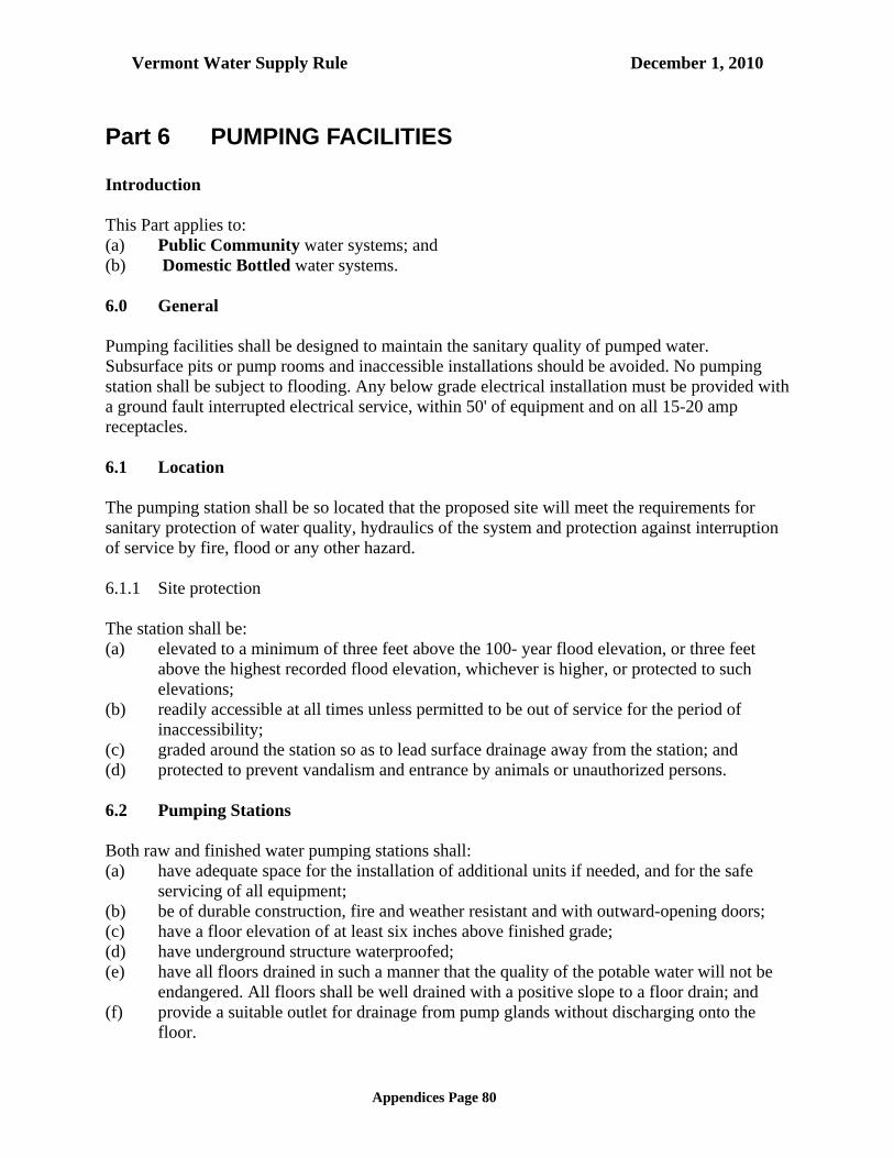
Vermont Water Supply Rule December 1, 2010
Appendices Page 80
Part 6 PUMPING FACILITIES Introduction This Part applies to: (a) Public Community water systems; and (b) Domestic Bottled water systems. 6.0 General Pumping facilities shall be designed to maintain the sanitary quality of pumped water. Subsurface pits or pump rooms and inaccessible installations should be avoided. No pumping station shall be subject to flooding. Any below grade electrical installation must be provided with a ground fault interrupted electrical service, within 50' of equipment and on all 15-20 amp receptacles. 6.1 Location The pumping station shall be so located that the proposed site will meet the requirements for sanitary protection of water quality, hydraulics of the system and protection against interruption of service by fire, flood or any other hazard. 6.1.1 Site protection The station shall be: (a) elevated to a minimum of three feet above the 100- year flood elevation, or three feet
above the highest recorded flood elevation, whichever is higher, or protected to such elevations;
(b) readily accessible at all times unless permitted to be out of service for the period of inaccessibility;
(c) graded around the station so as to lead surface drainage away from the station; and (d) protected to prevent vandalism and entrance by animals or unauthorized persons. 6.2 Pumping Stations Both raw and finished water pumping stations shall: (a) have adequate space for the installation of additional units if needed, and for the safe
servicing of all equipment; (b) be of durable construction, fire and weather resistant and with outward-opening doors; (c) have a floor elevation of at least six inches above finished grade; (d) have underground structure waterproofed; (e) have all floors drained in such a manner that the quality of the potable water will not be
endangered. All floors shall be well drained with a positive slope to a floor drain; and (f) provide a suitable outlet for drainage from pump glands without discharging onto the
floor.

Vermont Water Supply Rule December 1, 2010
Appendices Page 81
6.2.1 Suction well Suction wells shall: (a) be watertight; (b) have floors sloped to permit removal of water and entrained solids; and (c) be covered or otherwise protected against contamination. 6.2.2 Equipment servicing Pump stations shall be provided with: (a) craneways, hoist beams, eyebolts, or other adequate facilities for servicing or removal of
pumps, motors or other heavy equipment; (b) openings in floors, roofs, or wherever else needed for removal of heavy or bulky
equipment; and (c) a convenient tool board, or other facilities as needed, for proper maintenance of the
equipment. 6.2.3 Stairways and ladders Stairways or ladders shall: (a) be provided between all floors, and in pits or compartments which must be entered; (b) have handrails on both sides, and treads of non-slip material. Stairs are preferred in areas
where there is frequent traffic or where supplies are transported by hand. They shall have risers not exceeding nine inches and treads wide enough for safety; and
(c) conform to OSHA and VOSHA regulations covering these fixtures 6.2.4 Heating Provisions shall be made for adequate heating for: (a) the comfort of the operator; and (b) the safe and efficient operation of the equipment. In pump houses not occupied by personnel, only enough heat need be provided to prevent freezing of equipment or treatment processes. 6.2.5 Ventilation Ventilation shall conform to existing local and/or state codes. Adequate ventilation shall be provided for all pumping stations. Forced ventilation of at least six changes of air per hour shall be provided for: (a) all rooms, compartments, pits and other enclosures below ground floor; and (b) any areas where unsafe atmosphere may develop or where excessive heat may be built
up. 6.2.6 Dehumidification

Vermont Water Supply Rule December 1, 2010
Appendices Page 82
In areas where excess moisture could cause hazards to safety or damage to equipment, means for dehumidification should be provided. 6.2.7 Lighting Pump stations shall be adequately lighted throughout. All electrical work shall conform to the requirements of the American Insurance Associations and related agencies and to the relevant state and/or local codes. 6.2.8 Sanitary and Other Conveniences All pumping stations that are regularly occupied for extended periods should be provided with potable water, lavatory and toilet facilities. Plumbing must be so installed to prevent contamination of a Public water system. Wastes shall be discharged in accordance with Appendix A Subpart 4.10 and with other applicable regulations. 6.3 Pumps At least two pumping units shall be provided. With any pump out of service, the remaining pump or pumps shall be capable of providing the maximum daily pumping demand of the system. Pumping stations for Public Non-Community systems may be designed with one pumping unit. The pumping unit(s) shall: (a) have ample capacity to supply the peak demand without dangerous overloading. The
calculated peak demand should be no less than the total gpm obtained by using fixture methods outlined in, AWWA Manual M22, Sizing Water Service Lines and Meters, or the required fire flows if fire hydrants are provided for the system;
(b) be driven by a prime mover able to operate against the maximum head; (c) have spare parts and tools readily available; and (d) be served by control equipment that has proper heater and overload protection for air
temperature encountered. 6.3.1 Suction Lift Suction lift should: (a) be avoided, if possible; and (b) be within allowable limits, preferably less than 15 feet. If suction lift is necessary, provision shall be made for priming the pumps. 6.3.2 Priming Prime water must not be of lesser sanitary quality than that of the water being pumped. Means shall be provided to prevent back siphonage. When an air operated ejector is used, the screened intake shall draw clean air from a point at least 10 feet above the ground or other source of

Vermont Water Supply Rule December 1, 2010
Appendices Page 83
possible contamination, unless the air is filtered by an apparatus approved by the Secretary. Vacuum priming may be used. 6.4 Booster Pumps (Main Line) Booster pumps shall be located or controlled so that: (a) they will not produce negative pressure in their suction lines; (b) the intake pressure shall be at least 20 psi when the pump is in normal operation; (c) automatic cutoff pressure shall be at least 10 psi in the suction line; (d) automatic or remote control devices shall have a range between the start and cutoff
pressure which will prevent excessive cycling; and (e) a bypass is available. 6.4.1 Duplicate Pumps Each booster pumping station should contain not less than two pumps with capacities such that peak demand can be satisfied with the largest pump out of service. 6.4.2 Metering All booster pumping stations should contain a totalizer meter. 6.4.3 Inline Booster Pumps In addition to the other requirements of this part, inline booster pumps shall be accessible for servicing and repairs. 6.4.4 Individual Home Booster Pump Individual home booster pumps shall not be allowed for any individual service connection to the Public water system, unless installation is approved in writing by the Secretary, includes a properly sized and located air gap, and conforms to the Secretary’s guidelines. 6.5 Automatic & Remote Controlled Stations All automatic stations should be provided with automatic signaling apparatus which will report when the station is out of service. All remote controlled stations shall be electrically operated and controlled and shall have signaling apparatus of proven performance. Installation of electrical equipment shall conform with the applicable state and local electrical codes and the latest edition of the National Electrical Code. 6.6 Appurtenances 6.6.1 Valves

Vermont Water Supply Rule December 1, 2010
Appendices Page 84
Pumps shall be adequately valved to permit satisfactory operation, maintenance and repair of the equipment. If foot valves are necessary, they shall have a net valve area of at least 2.5 times the area of the suction pipe and they shall be screened. Each pump shall have a positive-acting check valve on the discharge side between the pump and the shutoff valve. 6.6.2 Piping
In general, piping shall: (a) be designed so that the friction losses will be minimized; (b) not be subject to contamination; (c) have watertight joints; (d) be protected against surge or water hammer; and (e) be such that each pump has an individual suction line or that the lines shall be so
manifolded that they will insure similar hydraulic and operating conditions. 6.6.3 Gauges and Meters Each pump: (a) shall have a standard pressure gauge on its discharge line; (b) shall have a compound gauge on its suction line; (c) shall have recording gauges in the larger stations; and (d) should have a means for measuring the discharge. The station should have indicating, totalizing, and recording metering of the total water pumped. 6.6.4 Water Seals Water seals shall not be supplied with water of a lesser sanitary quality than that of the water being pumped. Where pumps are sealed with potable water and are pumping water of lesser sanitary quality, the seal shall: (a) be provided with a break tank open to atmospheric pressure; and (b) have an air gap of at least six inches or two pipe diameters, whichever is greater, between
the feeder line and the spill line of the tank. 6.6.5 Controls Pumps, their prime movers and accessories, shall be controlled in such a manner that they will operate at rated capacity without dangerous overload. Where two or more pumps are installed, provision shall be made for alteration. Provision shall be made to prevent energizing the motor in the event of a backspin cycle. Electrical controls shall be located above grade. 6.6.6 Water Prelubrication When automatic pre lubrication of pump bearings is necessary and an auxiliary direct drive power supply is provided, the pre-lubrication line shall be provided with a valved bypass around

Vermont Water Supply Rule December 1, 2010
Appendices Page 85
the automatic control so that the bearings can, if necessary, be lubricated manually before the pump is started or the pre lubrication controls shall be wired to the auxiliary power supply. 6.6.7 Standby power
To ensure continuous service when the primary power has been interrupted, a power supply shall be provided from at least two independent sources or a standby or an auxiliary source shall be provided. If standby power is provided by onsite generators or engines the fuel storage and fuel line must be designed to protect the water system from contamination. Natural gas or bottled gas is the preferred fuel. This requirement may be waived for small sized systems on a case by case basis.

Vermont Water Supply Rule December 1, 2010
Appendices Page 86
Part 7 FINISHED WATER STORAGE Introduction This Part applies to: (a) Public Community water systems; and (b) Domestic Bottled water systems. 7.0 General The materials and designs used for finished water storage structures shall provide stability and durability as well as protect the quality of the stored water. Steel structures shall follow the current AWWA standards concerning steel tanks, standpipes, reservoirs, and elevated tanks wherever they are applicable. Other materials of construction are acceptable when properly designed to meet the requirements of Appendix A Part 7. Design for cast-in-place and pre-cast concrete structures must show the placement of structural steel and specify the material for sealing the joints. 7.0.1 Sizing Storage facilities shall have sufficient capacity, as determined from engineering studies, to meet average daily domestic demands, and where fire protection is provided, fire flow demands.
(a) When fire protection is provided, the minimum flow requirement shall be 500 gpm at 20 p.s.i. system residual pressure for a 2-hour duration for residential structures. If the Insurance Services Office or a other responsible agency (e.g., local fire department) recommends a higher flow rate than this minimum, the higher flow rate should be considered.
(b) The minimum storage capacity (or equivalent capacity) for systems not providing fire
protection shall be equal to the average daily demand. This requirement may be reduced when the source and treatment facilities have sufficient capacity with standby power to supplement peak demands of the system.
(c) Level control is recommended but low water level alarm is required for Public
Community water systems. (See Appendix A Subpart 7.3.3) 7.0.2 Location of ground level reservoirs (a) The bottom of reservoirs and standpipes shall be above maximum flood level. Steel and
glass fused to steel water storage tanks shall be placed at the normal ground surface. Cast in place and pre-cast, pre-stressed concrete storage structures may be partially buried. In order to determine the location of other materials, consult with the Secretary’s staff.
(b) The bottom of any reservoir or standpipe shall be placed above the groundwater table. Artificially lowering the groundwater table is acceptable. Sewers, drains, standing water,

Vermont Water Supply Rule December 1, 2010
Appendices Page 87
and similar sources of possible contamination must be kept at least fifty feet from the reservoir. Water main pipe, pressure tested in place to 50 psi without leakage, may be used for gravity sewers at distances greater than 20 feet and less than 50 feet.
(c) The top of a reservoir shall not be less than two feet above normal ground surface. Clear wells constructed under filters may be exempted from this requirement when the total design gives the same protection.
7.0.3 Location of Below Grade Reservoirs Below grade installation may be acceptable for reservoirs. Provisions shall be made to minimize the risk of reservoir damage and the tendency of the tank to float during high groundwater conditions. The top of any earth covered reservoir shall be covered with a flexible waterproof membrane as approved by the Secretary. 7.0.4 Protection All finished water storage structures shall have suitable watertight roofs which exclude birds, animals, insects, and excessive dust and shall have a perimeter drain at least 4" in diameter, if determined to be necessary, on a case-by-case basis. 7.0.5 Protection from Trespassers Necessary precautions shall be provided to deter trespassing, vandalism, and sabotage. 7.0.6 Inflow and Outflow Inflow and outflow shall be positioned so as to maximize chlorine contact time, if applicable. 7.0.7 Drains No drain on a water storage structure may have a direct connection to a sewer or storm drain. The design shall allow draining the storage facility for cleaning or maintenance without causing loss of pressure in the distribution system. 7.0.8 Overflow All water storage structures shall be provided with an overflow which should terminate 12 to 24 inches above the ground surface, and discharges over a drainage inlet structure or a splash plate. No overflow may be connected directly to a sewer or storm drain. All overflow pipes shall be located so that any discharge is visible. (a) The overflow shall be constructed of metallic pipe open downward and be screened with
24 mesh non-corrodible screen installed within the pipe at a location least susceptible to damage by vandalism.
(b) The overflow pipe shall be of sufficient diameter to permit discharge of water in excess of the filling rate.

Vermont Water Supply Rule December 1, 2010
Appendices Page 88
(c) When an internal overflow pipe is used on elevated tanks it shall be located in the access tube. For vertical drops on the other types of storage facilities, the over flow pipe shall be located on the outside of the structure.
7.0.9 Access Finished water storage structures shall be designed with reasonably convenient access to the interior floor for cleaning and maintenance. Entrances above the water line shall: (a) be framed at least four inches, and preferably six inches, above the surface of the roof at
the opening. On ground level structures, entrances should be elevated at least 18 inches above the top or covering sod;
(b) be fitted with a solid watertight cover which overlaps the framed opening and extends down around the frame at least two inches;
(c) be hinged at one side; and (d) have a locking device. 7.0.10 Vents Finished water storage structures shall be vented. Overflows shall not be considered as vents. Open construction between the sidewall and roof is not permissible. Vents shall: (a) be made of metallic or other durable pipe; (b) prevent the entrance of surface water and rainwater; (c) exclude birds and animals; (d) will exclude insects and dust, as much as this function can be made compatible with
effective venting, (for elevated tanks and standpipes, four mesh non-corrodible screen may be used);
(e) on ground level structures, terminate in an inverted J construction with the opening 24 to 36 inches above the roof or sod and protected with 24 mesh non-corrodible screen installed within the pipe at a location least susceptible to vandalism; and
(f) be adequately sized to keep the effects of negative pressure safely within the design load of the structure.
7.0.11 Roof and sidewall The roof and sidewalls of all structures must be watertight with no openings except properly constructed vents, manholes, overflows, risers, drains, pump mountings, control ports, or piping for inflow and outflow. (a) Any pipes running through the roof or sidewall of a finished water storage structure must
be welded, or properly gasketed in metal tanks. In concrete tanks, these pipes shall be connected to standard wall castings which were poured in place during the forming of the concrete. These wall castings should have seepage rings imbedded in the concrete.
(b) Openings in a storage structure roof or top, designed to accommodate control apparatus or pump columns, shall be curbed and sleeved with proper additional shielding to prevent the access of surface or floor drainage water into the structure.

Vermont Water Supply Rule December 1, 2010
Appendices Page 89
(c) Valves and controls should be located outside the storage structure so that the valve stems and similar projections will not pass through the roof or top of the reservoir.
(d) The roof of concrete reservoirs with earthen cover shall be sloped to facilitate drainage. Consideration shall be given to installation of an impermeable roof covering.
7.0.12 Drainage of roof The roof of the storage structure shall be well drained. Down spout pipes shall not enter or pass through the reservoir parapets, or similar construction which would tend to hold water and snow on the roof, will not be approved unless adequate waterproofing and drainage are provided. 7.0.13 Safety The safety of employees must be considered in the design of the storage structure. As a minimum, such matters shall conform to pertinent laws and regulations of the area where the reservoir is constructed. (a) Ladders, ladder guards, balcony railings, and safely located entrance hatches shall be
provided where applicable. (b) Elevated tanks with riser pipes over eight inches in diameter shall have protective bars
over the riser openings inside the tank. (c) Railings or handholds shall be provided on elevated tanks where persons must transfer
from the access tube to the water compartment. 7.0.14 Freezing All finished water storage structures and their appurtenances, especially the riser pipes, overflows, and vents, shall be designed to prevent freezing which could interfere with proper functioning. 7.0.15 Internal catwalk Every catwalk over finished water in a storage structure shall have a solid floor with raised edges so designed that shoe scrapings and dirt will not fall into the water. 7.0.16 Silt stop The discharge pipes from all reservoirs shall be located in a manner that will prevent the flow of sediment into the distribution system. Removable silt stops should be provided. 7.0.17 Grading The area surrounding a ground level structure shall be graded in a manner that will prevent surface water from standing within 50 feet of it.

Vermont Water Supply Rule December 1, 2010
Appendices Page 90
7.0.18 Painting and/or cathodic protection Proper protection shall be given to metal surfaces by paints or other protective coatings, by cathodic protective devices, or by both. (a) Paints systems shall be acceptable to the Secretary (either EPA or NSF approved).
Interior paint must be properly applied and cured. After curing, the coating shall not transfer any substances to the water which will be toxic or cause tastes or odors. Prior to placing in service, an analysis for volatile organic compounds is required to establish that the coating is properly cured.
(b) Wax coatings for the tank interior should not be used on new tanks. Re coating with a
wax system is discouraged; however, the old wax coating must be completely removed to use another tank coating.
(c) Cathodic protection should be designed and installed by competent technical personnel; a
maintenance contract should be provided. 7.0.19 Disinfection (a) Finished water storage structures shall be disinfected in accordance with current AWWA
Standard C652. Two or more successive sets of samples, taken at 24 hour intervals, shall indicate microbiologically satisfactory water before the facility is placed into operation.
(b) Disposal of heavily chlorinated water from the tank disinfection process shall be in
accordance with the requirements of the Secretary. (c) The disinfection procedure (AWWA chlorination method 3, section 4.3 C652) which
allows use of the chlorinated water held in the storage tank for disinfection purposes is not recommended. When that procedure is used, it is required that the initial heavily chlorinated water be properly disposed in order to prevent release of water which may contain various chlorinated organic compounds into the distribution system.
7.1 Plant Storage The applicable design standards of Appendix A Subpart 7.0 shall be followed for plant storage. 7.1.1 Washwater tanks Washwater tanks shall be sized, in conjunction with available pump units and finished water storage, to provide the backwash water required by Appendix A Subpart 4.2.1.10. Consideration shall be given to the backwashing of several filters in rapid succession. 7.1.2 Clear well

Vermont Water Supply Rule December 1, 2010
Appendices Page 91
Clear well storage should be sized, in conjunction with the distribution system storage, to relieve the filters from having to follow fluctuations in water use. (a) When finished water storage is used to provide contact time for chlorine (see Appendix A
Subpart 4.3.2) special attention shall be given to size and baffling. (b) An overflow shall be provided. 7.1.3 Adjacent compartments Finished water must not be stored or conveyed in a compartment adjacent to unsafe water when the two compartments are separated by a single wall. 7.1.4 Basins and wet wells Receiving basins and pump wet wells for finished water shall be designed as finished water storage structures. 7.2 Hydropneumatic Tanks Hydropneumatic (pressure) tanks, when provided as the only storage facility, are acceptable only in very small water systems. When serving more than 150 living units, ground or elevated storage designed in accordance with Appendix A Subpart 7.0.1 should be provided. Pressure tank storage is not to be considered for fire protection purposes. Pressure tanks shall meet ASME code requirements. 7.2.1 Location The tank should be located above the normal ground surface and be completely housed, except that a pressure tank may be placed below grade within a building served by the system if adequate drainage and access are provided. 7.2.2 Sizing (a) The capacity of the pumps in a hydropneumatic system should be at least ten times the
average daily consumption rate or capable of meeting the peak instantaneous demand (See Appendix A Subpart 6.3). The usable volume of the hydropneumatic tank, in gallons, should be chosen from the following table based upon the type, horsepower and average capacity rated in gallons per minute of the largest pump in the system. For example, a 3/4 horsepower, single phase submersible pump rated at 20 gpm would require a pressure tank with a usable volume of 24 gallons.
Submersible Pumps
Pump Motor Rating Cycles per Hour Usable Tank VolumeUp to:¾ HP single phase or5 HP three phase 12.5 1.2 x PC 1 to 5 HP single phase or7½ HP & over three phase 4.17 3.6 x PC 7½ HP & over single phase 2 7.5 x PC

Vermont Water Supply Rule December 1, 2010
Appendices Page 92
Non-submersible Pumps Pump Motor Rating Cycles per Hour Usable Tank Volume All horsepower and phases 2 2.5 x PC
* PC = capacity of largest pump in gpm (b) Sizing of hydropneumatic storage tanks must consider the need for chlorine detention
time, as applicable, independent of the requirements in Appendix A Subpart 7.2.2.a above.
7.2.3 Piping The tank shall have bypass piping to permit operation of the system while it is being repaired or painted. 7.2.4 Appurtenances Each tank without a separate air bladder shall have an access hole, a drain, and control equipment consisting of pressure gauge, water sight glass, automatic or manual air blow-off, means for adding air, and pressure operated start-stop controls for the pumps. Where practical the access manhole should be 24 inches in diameter. 7.3 Distribution Storage The applicable design standards of this subpart shall be followed for distribution system storage. 7.3.1 Pressures The maximum variation between high and low levels in storage structures providing pressure to a distribution system should not exceed 30 feet. The minimum working pressure in the distribution system should be 35 psi and the normal working pressure should be approximately 60 psi. When static pressures exceed 100 psi, pressure reducing devices should be provided on mains in the distribution system. 7.3.2 Drainage Storage structures which provide pressure directly to the distribution system shall be designed so they can be isolated from the distribution system and drained for cleaning or maintenance without necessitating loss of pressure in the distribution system. The drain shall discharge to the ground surface with no direct connection to a sewer or storm drain.

Vermont Water Supply Rule December 1, 2010
Appendices Page 93
7.3.3 Level Controls Controls shall be provided to maintain levels in distribution system storage structures. Level indicating devices should be provided at a central location. Low level alarms are required. (a) Pumps should be controlled from tank levels with the signal transmitted by telemetering
equipment when any appreciable head loss occurs in the distribution system between the source and the storage structure.
(b) Altitude valves or equivalent controls may be required for second and subsequent structures on the system.
(c) Overflow and low-level warnings or alarms shall be located at places in the community where they will be under responsible surveillance 24 hours a day. This requirement does not apply to Public Non-Community water systems.
(d) The low water level control shall be high enough so that the water system operator has time to correct the problem before a water shortage occurs.

Vermont Water Supply Rule December 1, 2010
Appendices Page 94
Part 8 DISTRIBUTION SYSTEMS Introduction This Part applies to: (a) Public Community water systems; and (b) Domestic Bottled water systems. 8.0 Materials 8.0.1 Standards, Materials Selection Pipe, fittings, valves and fire hydrants shall conform to the latest standards issued by the AWWA. Special attention shall be given to selecting pipe materials which will protect against both internal and external pipe corrosion. 8.0.2 Used materials Water mains which have been used previously for conveying potable water may be reused provided they meet the above standards and have been restored practically to their original condition. 8.0.3 Joints Packing and jointing materials used in the joints of pipe shall meet the standards of the AWWA, C-111. Pipe having mechanical joints or slip-on joints with rubber gaskets is preferred. 8.1 Water Main Design 8.1.1 Pressure All water mains, including those not designed to provide fire protection, shall be sized after a hydraulic analysis based on flow demands and pressure requirements. The system shall be designed to maintain a minimum pressure of 20 psi at ground level at all points in the distribution system under all conditions of flow. The normal working pressure in the distribution system should be approximately 60 psi and not less than 35 psi. 8.1.2 Diameter The minimum size of water main for providing fire protection and serving fire hydrants shall be eight inch diameter. Larger size mains will be required if necessary to allow the withdrawal of the required fire flow while maintaining the minimum residual pressure specified in Appendix A Subpart 8.1.1. 8.1.3 Fire Protection

Vermont Water Supply Rule December 1, 2010
Appendices Page 95
When fire protection is to be provided, system design shall meet the minimum flow standards in Appendix A, Part 7.0.1. 8.1.4 Small Mains Any departure from minimum requirements shall be justified by hydraulic analysis and future water use, and will be considered only in special circumstances. 8.1.5 Hydrants Water mains not designed to carry fire flows shall not have fire hydrants connected to them. 8.1.6 Dead ends Dead ends shall be minimized by looping of all mains whenever practical. 8.1.7 Flushing Where dead end mains occur they shall be provided with a fire hydrant if flow and pressure are sufficient, or with an approved flushing hydrant or blow off for flushing purposes. Flushing devices should be sized to provide flows which will give a velocity of at least 2.5 feet per second in the water main being flushed. No flushing device shall be directly connected to any sewer. The open end of a blow off must be capped and terminate at least 18 inches above grade. 8.2 Valves Sufficient valves shall be provided on water mains so that inconvenience and sanitary hazards will be minimized during repairs. Valves should be located at not more than 500 foot intervals in commercial districts, at not more than one block or 800 foot intervals in other districts, and at not more than 5000 foot intervals on transmission lines. 8.3 Hydrants 8.3.1 Location and spacing Hydrants should be provided at each street intersection and at intermediate points between intersections as recommended by the state Insurance Services Office. Generally, hydrant spacing may range from 350 to 600 feet depending on the area being served. 8.3.2 Valves and nozzles Fire hydrants should have a bottom valve size of at least five inches in diameter, one 4.5 inch diameter pumper nozzle and two 2.5 inch diameter nozzles. 8.3.3 Hydrant leads

Vermont Water Supply Rule December 1, 2010
Appendices Page 96
The hydrant lead shall be a minimum of six inches in diameter. Auxiliary valves shall be installed in all hydrant leads. 8.3.4 Drainage Hydrant drains should be plugged. When the drains are plugged the barrels must be pumped dry after use during freezing weather. Where hydrant drains are not plugged, a gravel pocket or dry well shall be provided unless the natural soils will provide adequate drainage. Hydrant drains shall not be connected to or located within 10 feet of sanitary sewers or storm drains. 8.4 Air Relief Valves: Valve, Meter & Blow-Off Chambers 8.4.1 Air relief valves At high points in water mains where air can accumulate, provisions shall be made to remove the air by means of hydrants or air relief valves. Automatic air relief valves shall not be used in situations where flooding of the accessway or chamber may occur. 8.4.2 Air relief valve piping The open end of an air relief pipe from the automatic valve shall be extended to at least 1 foot above grade and provided with a screened, downward-facing elbow. The pipe from a manually operated valve shall be extended to the top of the pit. 8.4.3 Chamber drainage Chambers, pits or manholes containing valves, blow-offs, meters, or other such appurtenances to a distribution system, shall not be connected directly to any storm drain or sanitary sewer, nor shall blow-offs or air relief valves be connected directly to any sewer. Such chambers or pits shall be drained to the surface of the ground where they are not subject to flooding by surface water, or to absorption pits underground. 8.5 Installation of Mains 8.5.1 Standards 8.5.1.1 Job specifications shall incorporate applicable provisions of the AWWA Standards.
Manufacturer's recommended installation procedures may be specified when they are equal to or better than AWWA procedures.
8.5.1.2 Piping, fittings and appurtenances which have been previously used for purposes other
than for Public water system use shall not be used in a Public water system without the written approval of the Secretary.
8.5.2 Bedding

Vermont Water Supply Rule December 1, 2010
Appendices Page 97
A continuous and uniform bedding shall be provided in the trench for all buried pipe. Back fill material shall be tamped in layers around the pipe and to a sufficient height above the pipe to adequately support and protect the pipe. Stones found in the trench shall be removed for a depth of at least six inches below the bottom of the pipe. 8.5.3 The open ends of exposed pipe shall be left plugged in excavations at the conclusions of
the day's work. During periods of delay and at the conclusion of the day's work, lengths of pipe with open ends shall be tightly closed with watertight plugs, special seals or by other suitable means to prevent the entry of animals, foreign matter and trench water. Trench water shall be pumped out before the seals, plugs or other closures are removed.
8.5.4 Cover All water mains shall be covered with at least 5.5 feet of earth. Insulation may be used in lieu of cover depth when approved in advance by the Secretary. 8.5.5 Thrust Blocks All tees, bends, plugs and hydrants shall be provided with reaction blocking, tie rods or joints designed to prevent movement. Specifications shall include a requirement that all air be removed from the pipes before water at test pressure levels is added. Size of blocks shall be specified and design basis shown (i.e. type of soil, design water pressure used). 8.5.6 Pressure and leakage testing All types of installed pipe shall be pressure tested and leakage tested in accordance with the latest edition of AWWA Standard C600. 8.5.7 Disinfection All new, cleaned or repaired water mains shall be disinfected in accordance with AWWA Standard C651, latest published version. The specifications shall include detailed procedures for the adequate flushing, disinfection, and microbiological testing of all water mains. If bacterio-logical tests show the treatment to be unsatisfactory, the disinfection procedures shall be repeated until satisfactory bacteriological sample results are obtained. The tablet method in AWWA Standard 651 is not acceptable. 8.6 Separation of Water Mains, Sanitary Sewers, Storm Sewers & Other Sources of
Contamination 8.6.1 General The following factors should be considered in providing adequate separation: (a) materials and type of joints for water and sewer pipes; (b) soil conditions;

Vermont Water Supply Rule December 1, 2010
Appendices Page 98
(c) service and branch connections into the water main and sewer line; (d) compensating variations in the horizontal and vertical separations; (e) space for repair and alterations of water and sewer pipes; and (f) off-setting of pipes around manholes. 8.6.2 Parallel installation Water mains shall be laid at least 10 feet horizontally from any existing or proposed manhole or sanitary sewer. This distance can be reduced to 5 feet for storm sewers. The distance shall be measured edge to edge. In cases where it is not practical to maintain a 10 foot separation, the Secretary may allow deviation on a case-by-case basis if supported by data from the design engineer. Such deviation may allow installation of the water main closer to a sewer, provided that the water main is laid in a separate trench or on an undisturbed earth shelf located on one side of the sewer at such an elevation that the bottom of the water main is at least 18 inches above the top of the sewer. See Appendix A Subpart 8.6.4 for approval required for such exception. 8.6.3 Crossings Water mains crossing sewers shall be laid to provide a minimum vertical distance of 18 inches between the outside of the water main and the outside of the sewer. This shall be the case where the water main is either above or below the sewer. At crossings, one full length of water pipe shall be located so both joints will be as far from the sewer as possible. If the sewer main is over the water main, the first sewer pipe joints on each side of the water main must be concrete encased. Special structural support for the water and sewer pipes may be required. Water mains shall not pass through sewer manholes or be submerged in basins containing sewage or other grossly contaminated or hazardous material. Stream crossings shall meet the provisions of Appendix A Subpart 8.7. 8.6.4 Exception The Secretary must specifically approve any variance from the requirements of Appendix A Subparts 8.6.2, 8.6.3, 8.6.6 and 8.6.7 when it is impossible to obtain the specified separation distances. Where sewers are being installed and Appendix A Subparts 8.6.2 and 8.6.3 cannot be met, the sewer materials shall be water main pipe or equivalent and shall be pressure tested to ensure water tightness. 8.6.5 Force mains There shall be at least a 10 foot horizontal separation between water mains and sanitary sewer force mains. There shall be an 18 inch vertical separation at crossings as required in Appendix A Subpart 8.6.3. 8.6.6 Septic Tanks and Leach Fields

Vermont Water Supply Rule December 1, 2010
Appendices Page 99
Distribution lines shall be placed not closer than fifty (50) feet horizontal distance from any septic tank or leach field except as provided in Appendix A Subpart 8.6.4. 8.6.7 Other underground storage tanks Distribution lines shall be placed not closer than twenty five (25) feet horizontal distance from underground storage tanks. Fifty (50) feet separation is preferable except as provided in Appendix A Subpart 8.6.4. 8.7 Surface Water Crossings Surface water crossings, whether over or under water, present special problems. The Secretary shall be consulted before final plans are prepared. 8.7.1 Above-water crossings The pipe shall be adequately supported and anchored, protected from damage and freezing, and accessible for repair or replacement. 8.7.2 Underwater crossings A minimum cover of two feet shall be provided over the pipe. When crossing water courses greater than 15 feet in width, the following shall be provided: (a) the pipe shall be of special construction, having flexible water tight joints; (b) valves shall be provided at both ends of water crossings so that the section can be isolated
for testing or repair; the valves shall be easily accessible, and not subject to flooding; and the valve closest to the supply source shall be in a manhole; and
(c) permanent taps shall be made on each side of the valve within the manhole to allow insertion of a small meter to determine leakage and for sampling purposes.
8.8 Cross-Connections & Interconnections 8.8.1 Cross-connections There shall be no connection between the distribution system and any pipes, pumps, hydrants, or tanks whereby unsafe water or other contaminating materials may be discharged or drawn into the system. This does not preclude approved cross connection control devices. 8.8.2 Cooling water; Heating Water
(a) Neither steam condensate nor cooling water from engine jackets or other heat exchange
devices shall be returned to a public water supply. (b) Notwithstanding subsection (a) of this section, standing column geothermal systems are
allowed provided that: (1) No additive is added to the re-circulated groundwater :

Vermont Water Supply Rule December 1, 2010
Appendices Page 100
(2) The heat exchange medium in the system is R-410A or a different heat exchange medium approved by the Secretary;
(3) The system has a low pressure safety cutout circuit that will turn off the system when there is a pressure leak in the heat exchange medium containment vessel;
(4) All electrical components of the system are properly grounded to prevent potential electrolysis of metals; and
(5) In the event that the heat exchange unit is disconnected as a heating or cooling source, all piping associated with the unit shall either be capped and labeled or removed.
(c) For the purposes of this section, a standing column geothermal system is one where groundwater is taken from a public water supply well for heating and/or cooling purposes and re-circulated back into the same well below the estimated low water elevation of the well.
8.8.3 Interconnections Drains from the fire hydrants, air relief pits and blow off valve pits shall not connect directly to sewer lines or discharge at a point which will permit possible back siphonage conditions. The approval of the Secretary shall be obtained for interconnections between potable water systems. 8.9 Water Services & Plumbing 8.9.1 Plumbing Water services and plumbing shall conform to the state plumbing code. 8.9.2 Booster pumps Individual home booster pumps shall not be allowed for any individual service connection to the Public water system, unless installation is approved in writing by the Secretary, includes a properly sized and located air gap, and conforms to the Secretary’s guidelines. 8.10 Service Meters Each service connection should be individually metered. 8.11 Water Loading Stations Water loading stations present special problems since the fill line may be used for filling both potable water vessels and other tanks or contaminated vessels. To prevent contamination of both the Public system and potable water vessels being filled, the following principles shall be met in the design of water loading stations: (a) there shall be no backflow to the Public water system; (b) the piping arrangement shall prevent contaminant being transferred from a hauling vessel
to others subsequently using the station; and (c) hoses shall not be contaminated by contact with the ground.

Vermont Water Supply Rule December 1, 2010
Appendices Page 101
Part 9 (RESERVED)
Part 10 (RESERVED)

Vermont Water Supply Rule December 1, 2010
Appendices Page 102
Part 11 NON-COMMUNITY AND NON-PUBLIC WATER SYSTEMS 11.1 Introduction and Definitions 11.1.0 General This part provides regulation and guidance for potable water sources, storage, and distribution systems serving Public Non-Transient Non-Community water systems, Public Transient Non-Community water systems, and Non-Public water systems requiring a permit. Information to be submitted with permit applications, methodologies to be used in source evaluation, and minimum standards for construction and operation of such systems are provided. Public Transient Non-Community water systems are initially administered by the Regional Offices of the Department's Wastewater Management Division and then the Department’s Water Supply Division has responsibility for them. The addresses and telephone numbers for the Regional Offices are contained in the introduction to this rule. These standards and limits represent minimum criteria. Designers should note that the use of this part requires professional judgement. The standards are minimal and the safety factors are marginal, and will not yield satisfactory designs, by themselves, in all situations. These regulations have two principal goals: (a) the prevention of health hazards caused by water sources of inadequate quality and
quantity; and (b) the assurance that water sources and distribution systems are adequate for the needs of a
project. Owners are urged to furnish potable water for their projects by connection to a Public Community water system if feasible. 11.1.1 Alternative Designs The professional engineer may propose alternative engineering designs for water systems and justify the design based on its reliability in providing water of adequate quality and quantity for the size and nature of the project. 11.1.2 Definitions The following definitions apply for the purposes of this Part (Appendix A Part 11); additional definitions are contained in Subchapter 21-2. AVERAGE DAY DEMAND - The volume of water anticipated to be used by a particular building or project in a 24 hour period; expressed in gallons per day (gpd).

Vermont Water Supply Rule December 1, 2010
Appendices Page 103
CONSTANT DISCHARGE PUMPING TEST - A test of a water source in which the well is pumped for a specified duration at one flow rate to determine the yield of the well, aquifer characteristics and/or well interference. FLOOD PLAIN - Any area which is flooded with an average frequency of once or more in each 100 years as determined by the Secretary. FLOODWAY - The channel of a river or other water course and the adjacent land areas that must be reserved in order to discharge a 100 year frequency flood without cumulatively increasing the water surface elevation more than one foot. HYDROFRACTURING - A method of bedrock well development used to increase the yield of wells, in which high pressures are generated in the well to open fractures. Propping agents may be introduced to keep the fractures open. HYDROGEOLOGIC CONNECTION - A situation where a water source is down- gradient of a potential source of contamination under either natural groundwater flow conditions or pumping conditions. INSTANTANEOUS PEAK DEMAND - The instantaneous flow rate that the system must satisfy. This is determined by the number and type of plumbing fixtures on it. LICENSED WELL DRILLER - An individual licensed under the Vermont Well Driller Licensing Rules and Standards. LONG-TERM YIELD - The amount of water that the source is capable of providing on a daily basis over the design life of the project; expressed in gallons per minute (gpm). MAXIMUM DAY DEMAND - For Public Non-Transient Non-Community water systems, Public Transient Non-Community water systems, and Non-Public water systems requiring a permit water systems, the rate at which the average day demand is to be used by a particular building or project divided by not more than 720 minutes; expressed in gallons per minute (gpm). NON-PUBLIC WATER SYSTEM REQUIRING A PERMIT - Any water system or systems designed to provide potable water under pressure for human consumption, from groundwater and serve projects requiring a water supply and wastewater permit in accordance with 10 V.S.A. §1973. This definition does not include Public water systems. QUALIFIED CONSULTANT - Certified Site Technician, or Vermont Registered Professional Engineer, working within the scope of his or her certification and expertise. SHALLOW WATER SOURCE - A developed structure to collect groundwater, generally less than 20 feet deep. This includes springs, dug wells, jetted wells, drilled wells, and well points, and other water intake structures which may or may not be under the jurisdiction of the Vermont Well Driller's Rules and Construction Standards.

Vermont Water Supply Rule December 1, 2010
Appendices Page 104
SOURCE INTERFERENCE - Public and private water systems affected by the pumping of other proposed or existing sources. STATE ELECTRICAL CODE - State of Vermont Electrical Safety Rule adopted by the Vermont Department of Public Safety per 26 V.S.A. §891. STATE PLUMBING CODE - State of Vermont Plumbing Rule, adopted by the Vermont Department of Public Safety per 26 V.S.A. §2173. TOTAL AVAILABLE HEAD - The difference in elevation between the static water level and the hydraulic base of a well. WATER SOURCE - An existing or permitted water well or shallow water source designed to collect potable groundwater. WATER SYSTEM - The source, pumping facility, storage, distribution system and related appurtenances used to provide potable water. 11.2 Preconstruction Requirements 11.2.0 General For all Public Non-Transient Non-Community water systems, Public Transient Non-Community water systems, and Non-Public water systems requiring a permit, a water source site plan, basis of design statement, and design plans and specifications, along with all available information on the source, must be submitted with the permit application. In addition, a Long Range Plan, Source Protection Plan, and Engineer’s Report, as required by Subchapters 4.2.2, 5.5(e), 15.1, and 16.1, must be submitted for new Public Non-Transient Non-Community water systems. Some of this information may be developed in pre-application work and may require review and approval by the Secretary before an application will be considered complete. Increased demands to existing or previously approved Public Non-Transient Non-Community water systems, Public Transient Non-Community water systems, and Non-Public water systems requiring a permit water systems will require analysis of additional maximum day demand and/or instantaneous peak demand. 11.2.1 Basis of Design A statement of the basis of design, and supporting calculations, shall include: (a) Average Day Demand; (b) Maximum Day Demand; (c) Instantaneous Peak Demand; (d) Source Capacity; (e) Storage Capacity;

Vermont Water Supply Rule December 1, 2010
Appendices Page 105
(f) Pump Capacities; (g) Operating Pressure Ranges; and (h) reference to the flood plain 11.2.2 Water Source Site Plan A water source site plan shall include: (a) plan view at a scale of 1" = 200', or larger; (b) surface drainage features and general topography; (c) potential sources of contamination within the distances listed in Appendix A Part 11
Tables 11-1 and 11-2; (d) neighboring wells as shown in the interference monitoring distance table; and (e) minimum separation zones per Appendix A Subpart 11.4.1. 11.2.3 Design Plans and Specifications The design plans and specifications shall include: (a) source development, transmission, storage and distribution; (b) system component site plan at a scale of 1" = 100', or larger; (c) piping, valving and standard pressure; and (d) specific construction instructions. 11.2.4 Source Development and Testing 11.2.4.1 Projects with Maximum Day Demand of 5 gpm or less These projects will be permitted prior to water source development unless there is reason to suspect that sufficient water may not be available, in which case the Secretary may: (a) require that the water source be developed and tested before the permit is issued; or (b) issue a permit with a condition that the water source be developed and tested before a
subdivision is created, a building is constructed or a mobile home park is established. 11.2.4.2 Projects with Maximum Day Demand of More Than 5 gpm These projects will not normally be permitted before the source is developed and tested, unless: (a) the applicant demonstrates a high probability of adequate yield and quality from the
proposed water source. In such a case the source must be developed, tested and analyzed in accord with Subpart 11.6 prior to the creation of subdivision lots, construction of buildings or the establishment of a mobile home park; or
(b) site and foundation construction may be approved under Section 1-405 of the Wastewater System and Potable Water Supply Rules, effective August 16, 2002, for public buildings only, when the applicant demonstrates that there is a high probability that a water source with adequate yield and quality can be developed for the project. In such a case, the source shall be developed and analyzed in accord with Appendix A Subpart 11.6, and final design of the water system submitted to the Secretary for review

Vermont Water Supply Rule December 1, 2010
Appendices Page 106
and approval with appropriate permit application and fee, before a permit can be issued or any buildings constructed.
11.2.4.3 Subdivision With Individual On-Site Sources These projects are normally approved prior to source development. Multiple lot subdivisions may need to show evidence that adequate yields are likely to be available, and/or that proposed sources are not likely to cause unacceptable interference in nearby existing or permitted water sources. 11.3 Water System Demand 11.3.0 Average Day Demand (a) For Public water systems, the average day demand shall be determined according to the
design flows per Appendix A, Part 2, Table A2-1 of this rule. (b) For Non-public water systems, the average day demand shall be determined according to
the design plan prepared according to the requirements of Chapter 1 of the Environmental Protection Rules.
(c) For residential units average day demand shall be 90% of the design flow. (d) Installation of low flow plumbing fixtures, 3.5 gallon or less flush toilets, 3.0 gallon per
minute or fewer showerheads, and faucet aerators will allow for a 10% reduction in design flows as calculated from Table A2-1.
11.3.1 Maximum Day Demand The maximum day demand is calculated by dividing the average day demand by not more than 720 minutes. The resulting flow rate is expressed in gallons per minute. 11.3.2 Instantaneous Peak Demand The instantaneous peak demand, expressed in gallons per minute (gpm), shall be calculated as follows: (a) determined by the State Plumbing Code; or (b) for residential units only, the instantaneous peak demand equals 5 gpm multiplied by the
number of units. 11.4 Isolation and Separation Distances 11.4.0 General The proposed site of the water source for the building or project shall be approved by the Secretary before the source is developed. Adequate horizontal isolation distances between wells and potential sources of contamination are required. The required horizontal minimum distances are listed in Tables A11-1 and A11-2

Vermont Water Supply Rule December 1, 2010
Appendices Page 107
below. Qualified consultants, Site Technicians, Professional Engineers or Hydrogeologists, as appropriate, are responsible for assuring that these minimums are adequate for individual cases, and should increase them as they deem appropriate in their professional judgement. The Secretary may increase the minimum horizontal isolation distances in Tables A11-1 and A11-2 or prescribe any additional safeguards it deems necessary when the depth to the aquifer or the nature of overburden material is not sufficient to protect the water source from pollution. The Secretary will consider permitting reductions of these individual cases only on the written request of the qualified consultants, which technically justifies the reduction in a particular case. The minimum recommended horizontal isolation distances in these regulations from water systems to sewage systems are based on sewage treatment in soils, pathogen attenuation, effluent travel time in soil and dispersion, without site specific hydrogeologic information. Site specific data may be collected and justification made for reducing the distances listed in Tables A11-1 and A11-2.
Table A11-1 - REQUIRED HORIZONTAL MINIMUM SEPARATION DISTANCES
POTENTIAL SOURCE OF CONTAMINATION AND OTHER SITING LIMITATIONS
SEPARATION DISTANCE
Roadway, Parking Lot (outer edge of shoulder) 25 Feet
Driveway (Fewer than 3 residences) 15 Feet
Sewage System Disposal Fields (See a.)
Subsurface Wastewater Piping and Related Tanks 50 Feet
Property Line 10 Feet (See b.)
Limit of Herbicide Application on utility R O W 100 Feet (See c.)
Surface Water 10 Feet (See d.)
Flood ways (See e.)
Buildings 10 Feet
Concentrated Livestock Holding Areas and Manure Storage Systems
200 Feet
Hazardous or Solid Waste Disposal Site (See f.)
Non-sewage Wastewater Disposal Fields (See f.) a. See Table A11-2 b. Increased to 50' when adjacent to agricultural cropland. c. Applies to rights-of-way (ROW) where herbicides have been applied in the past 12
months or may be applied in the future. This distance may be increased to 200' depending on the active ingredient in the herbicide according to Vermont Regulations for Control of Pesticides.
d. For Public water sources, see Appendix A, Part 3, Subpart 3.4. e. Water sources shall not be located in a flood way.
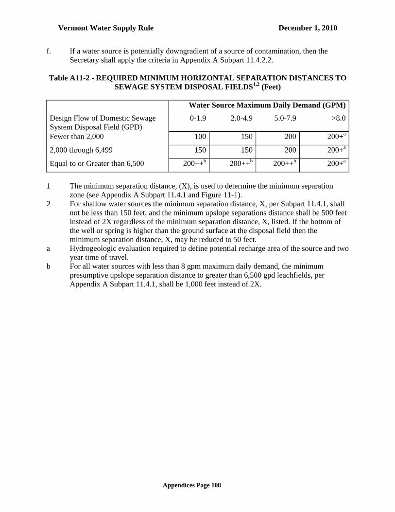
Vermont Water Supply Rule December 1, 2010
Appendices Page 108
f. If a water source is potentially downgradient of a source of contamination, then the Secretary shall apply the criteria in Appendix A Subpart 11.4.2.2.
Table A11-2 - REQUIRED MINIMUM HORIZONTAL SEPARATION DISTANCES TO
SEWAGE SYSTEM DISPOSAL FIELDS1,2 (Feet) Water Source Maximum Daily Demand (GPM)
Design Flow of Domestic Sewage System Disposal Field (GPD)
0-1.9 2.0-4.9 5.0-7.9 >8.0
Fewer than 2,000 100 150 200 200+a
2,000 through 6,499 150 150 200 200+a
Equal to or Greater than 6,500 200++b 200++b 200++b 200+a
1 The minimum separation distance, (X), is used to determine the minimum separation
zone (see Appendix A Subpart 11.4.1 and Figure 11-1). 2 For shallow water sources the minimum separation distance, X, per Subpart 11.4.1, shall
not be less than 150 feet, and the minimum upslope separations distance shall be 500 feet instead of 2X regardless of the minimum separation distance, X, listed. If the bottom of the well or spring is higher than the ground surface at the disposal field then the minimum separation distance, X, may be reduced to 50 feet.
a Hydrogeologic evaluation required to define potential recharge area of the source and two year time of travel.
b For all water sources with less than 8 gpm maximum daily demand, the minimum presumptive upslope separation distance to greater than 6,500 gpd leachfields, per Appendix A Subpart 11.4.1, shall be 1,000 feet instead of 2X.

Vermont Water Supply Rule December 1, 2010
Appendices Page 109
FIGURE 11-1.
PLAN VIEW OF REQUIRED MINIMUM SEPERATION
DISTANCES TO DOMESTIC SEWAGE DISPOSAL FIELDS1
Domestic Sewage System Disposal Field Design Flow
(gpd)
Water Source Maximum Daily Demand, MDD (gpm)
MDD < 2
2 < MDD
5 < MOD < 8
8 < MDD
< 2000
X = 100’
X= 200’
For water source with demands of 6 gpm or greater, the well must be located outside the 2 year time of travel of all effluent plume paths.
> 2000 and
< 6500
X = 150’
X = 200’
> 6500
X= 200’ For septic systems over 6500 gpd wells must be located outside the 2 year time of travel effluent plume path, or greater than 1000’ from the disposal fields.
1. These shapes assume parallel ground surface contours horizontally across page with a downslope direction toward the
bottom of the page.
a. For shallow water supplies X = 150’
b. For shallow water supplies use 500’ distance instead of 2X
2xb
xa
2xb 2xb
x x

Vermont Water Supply Rule December 1, 2010
Appendices Page 110
11.4.1.0 Separation Distances to Sewage System Disposal Fields Wells and sewage system disposal fields should be located to optimize the hydrogeologic separation within the project limitations. The applicant's designer must establish a separation zone around the water source which defines the probable area of groundwater recharge to the water source. The separation zone may be established by a presumptive method which uses ground surface topography and minimum distances. The minimum separation distances for leachfields can be also estimated by using methods to define Source Protection Areas in accord with procedures defined in this rule (see Appendix A Part 3), or with other methods approved by the Secretary. 11.4.1.1 Presumptive Minimum Separation Zone Methods for a Water Well To determine the size and shape of the required minimum separation zone between sewage disposal fields and a water well the following steps should be taken (see Figure 11-1): (a) draw a circle with a radius equal to the required minimum separation distance, X, from
Table A11-2, around the well head or water source; (b) now either:
(1) if the circle drawn intersects with the contour elevation of the source, then draw lines beginning at these intersections, extending upslope and perpendicular to the contours, until these lines intersect an arc with a radius equal to twice the minimum separation distance (2X) from the source. If necessary, to provide closure of the area draw an arc with radius 2X from the source; or
(2) if the circle drawn in Step 1 is in all cases at a lower elevation than the source elevation, no further delineation may be required (resulting in the smallest possible minimum separation zone of a circle with radius X); or,
(3) if the circle drawn in Step 1 is in all cases is above the elevation of the well, the water shed area or a circle with a radius of 2X, whichever is smaller, shall represent the minimum separation zone (resulting in the largest possible minimum separation zone of a circle with a radius 2X).
11.4.1.2 Presumptive Minimum Separation Zone Methods for a Shallow Water Source To determine the size and shape of the required minimum separation zone between sewage disposal fields and a shallow water source, the following steps should be taken (see Figure A11-1): (a) draw a circle with a radius equal to the required minimum separation distance, X, from
Table A11-2, around the well head or water source; (b) now either:
(1) if the circle drawn intersects with the contour elevation of the source, then draw lines beginning at these intersections, extending upslope and perpendicular to the contours, until these lines intersect an arc with a radius equal to 500 feet from the

Vermont Water Supply Rule December 1, 2010
Appendices Page 111
source. If necessary, to provide closure of the area draw an arc with radius of 500 feet from the source; or
(2) if the circle drawn in Step 1 is in all cases at a lower elevation than the source elevation, no further delineation may be required (resulting in the smallest possible minimum separation zone of a circle with radius X); or
(3) if the circle drawn in Step 1 is in all cases above the elevation of the well, the water shed area or a circle with a radius of 500 feet, whichever is smaller, shall represent the minimum separation zone (resulting in the largest possible minimum separation zone of a circle with a radius of 500 feet).
11.4.2.0 Requirements for Investigation of Potential Hydrogeologic Connections Between
Water Sources and Sewage Disposal Fields This subpart applies when a hydrogeologic connection may exist between a sewage system disposal field and a potable water source. These distances listed in Table A11-1 & A11-2 provide a minimal level of protection for water sources. These distances may be increased or reduced based on site specific data. 11.4.2.0.1 Increasing the Minimum Separation Zone These distances may be increased up to a maximum of 500 feet if a sewage disposal field is discharging upgradient of a water source and to the same unconsolidated, unconfined aquifer from which the water source is withdrawing. 11.4.2.0.2 Reduction of the Minimum Separation Zone These distances may be reduced with the use of site specific data under the following conditions: (a) If there is a continuous impeding layer from the sewage system disposal field to the well
head, and the well is properly sealed to prevent contaminant migration along the well casing then the minimum separation zone around the well head may be reduced to a radius of not less than 100 feet; or
(b) If the groundwater flow from beneath the sewage system disposal fields is not toward a minimum separation zone around the well head that has a radius of X; or
(c) If a detailed hydrogeologic investigation reveals that groundwater flow from beneath the sewage system disposal field does not flow toward the source under pumping conditions the minimum separation zone around the well head may be reduced to a radius of not less than 100 feet; or
(d) If a detailed hydrogeologic investigation demonstrates a time of travel exceeding two years in accordance with Appendix A Subpart 11.4.2.1, then the minimum separation zone around the well head may be reduced to a radius of not less than 100 feet.
(e) The horizontal isolation distance for non-public wells may be reduced to a minimum distance of 50 feet. The reduction will only be granted upon presentation of sufficient evidence that the site conditions, hydrogeology, and well construction ensure protection of the potable water system.

Vermont Water Supply Rule December 1, 2010
Appendices Page 112
11.4.2.1 Two Year Time of Travel If required elsewhere in Appendix A Subpart 11.4.2, then a minimum travel time of two years must exist in the materials between a potential source of contamination that may contain pathogenic microorganisms and the drinking water source. The two year travel time is based on the reasonable assurance of pathogen attenuation. Calculations of travel time must take into account hydraulic gradient, porosity, saturated hydraulic conductivities in the materials with the largest saturated hydraulic conductivity, the cone of influence of production wells or the recharge area of springs being considered, and mounding of the water table due to groundwater recharge by discharge of the sewage effluent. 11.4.2.2 Increased Level of Contamination The potential source(s) of contamination may not increase the level of contamination in any drinking water source to more than the Maximum Contaminant Levels (MCL) of the Drinking Water Standards in Subchapter 21-6 of this rule. Nitrate (expressed as N) may be used as an indicator when dealing with domestic (non-industrial) wastes. Calculations must take into account the concentration of nitrate-nitrogen at the base of the leachfield, which is assumed to be 40 mg/l, dilution by precipitation and groundwater flow, dispersion, background concentrations of nitrate-nitrogen, and other existing sources of nitrate-nitrogen, including fertilizers, in the subsurface drainage basin, using the assumption that no denitrification takes place in the subsoil. Methods of calculation and evaluation must closely approximate actual conditions and should be determined in consultation with the Secretary before any work is done. The minimum separation distances for leachfields can be also estimated by using methods to define Source Protection Areas as contained in Appendix A Part 3 or with other methods approved by the Secretary. 11.5 Well and Spring Construction Standards 11.5.0 Water Well The requirements of this subpart presume that water wells are constructed in compliance with Appendix A, Part 12 (Construction and Isolation Standards for Wells). 11.5.1 Spring and Shallow Well Construction 11.5.1.1 Materials Acceptable materials include: (a) concrete tiles (grouted together); (b) poured in place concrete; (c) well casing; and (d) other metallic or plastic casing as approved by the Secretary. 11.5.1.2 Site Work

Vermont Water Supply Rule December 1, 2010
Appendices Page 113
Spring and shallow well site construction shall include the following: (a) screened ventilation or overflow openings; (b) surface water diversion berm at least 50 feet upslope when feasible; (c) back fill material of high clay content sloping away from source; (d) minimum of 4 inches of top soil over the clay; (e) a watertight, rodent-proof sanitary cover; and (f) for public water systems, an entrance access hatch and lock. 11.6 Water Quantity Testing 11.6.0 Water Sources 11.6.0.1 Projects with a Maximum Day Demand of 5 gpm or less: These projects: (a) may use 50 percent of the well drillers estimated yield as long term yield; and (b) if project maximum day demand is greater than 50 percent of the well drillers estimated
yield, a constant discharge pumping test as defined in Appendix A Subpart 11.6.1 is required.
11.6.0.2 Projects with Maximum Day Demand of more than 5 gpm These projects shall conduct a constant discharge pumping test in accord with Subpart 11.6.1 to determine the long term yield of the well. 11.6.0.3 Springs A spring source shall require that the yield be determined by hydrogeologic flow analysis per Appendix A Subpart 11.6.1.2. Single family residences and projects classified as home occupations, shall be exempt from this requirement. 11.6.1 Long Term Yield Testing 11.6.1.1 Water Wells When a constant discharge test is required by the provisions of Appendix A Subpart 11.6.0, the following conditions shall be met: (a) the test shall be designed and analyzed by a qualified hydrogeologist, or a professional
engineer, who is proficient in well testing and analyses; (b) the test shall be conducted for the durations listed in Table A11-3 at a pumping rate
greater than or equal to the required maximum day demand of the well; (c) water level drawdown and rate of discharge shall be measured using accepted methods at
intervals that will plot evenly on a logarithmic scale graph; (d) the draw down measurements shall continue into the recovery period for two days or until
a minimum of 90% recovery is achieved whichever occurs first.
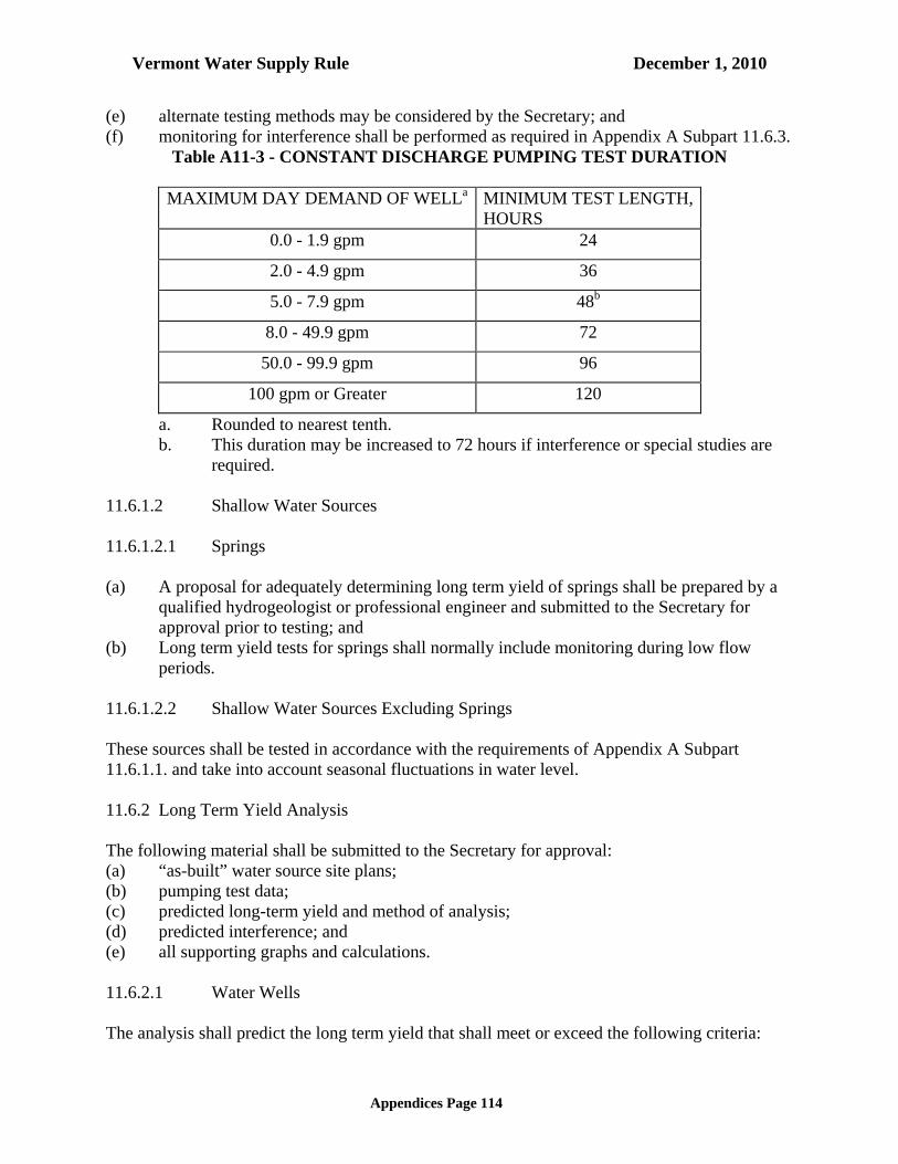
Vermont Water Supply Rule December 1, 2010
Appendices Page 114
(e) alternate testing methods may be considered by the Secretary; and (f) monitoring for interference shall be performed as required in Appendix A Subpart 11.6.3.
Table A11-3 - CONSTANT DISCHARGE PUMPING TEST DURATION
MAXIMUM DAY DEMAND OF WELLa MINIMUM TEST LENGTH, HOURS
0.0 - 1.9 gpm 24
2.0 - 4.9 gpm 36
5.0 - 7.9 gpm 48b
8.0 - 49.9 gpm 72
50.0 - 99.9 gpm 96
100 gpm or Greater 120
a. Rounded to nearest tenth. b. This duration may be increased to 72 hours if interference or special studies are
required. 11.6.1.2 Shallow Water Sources 11.6.1.2.1 Springs (a) A proposal for adequately determining long term yield of springs shall be prepared by a
qualified hydrogeologist or professional engineer and submitted to the Secretary for approval prior to testing; and
(b) Long term yield tests for springs shall normally include monitoring during low flow periods.
11.6.1.2.2 Shallow Water Sources Excluding Springs These sources shall be tested in accordance with the requirements of Appendix A Subpart 11.6.1.1. and take into account seasonal fluctuations in water level. 11.6.2 Long Term Yield Analysis The following material shall be submitted to the Secretary for approval: (a) “as-built” water source site plans; (b) pumping test data; (c) predicted long-term yield and method of analysis; (d) predicted interference; and (e) all supporting graphs and calculations. 11.6.2.1 Water Wells The analysis shall predict the long term yield that shall meet or exceed the following criteria:

Vermont Water Supply Rule December 1, 2010
Appendices Page 115
(a) constant withdrawal at the Average Day Demand for 180 days; and (b) drawdown shall not exceed 90 percent of the total available head. 11.6.2.2 Springs Analysis of monitoring data shall follow accepted hydrogeologic methods such as low flow analyses or other suitable methods. 11.6.2.3 Shallow Water Sources Excluding Springs Analyses shall be in accordance with Appendix A Subpart 11.6.2.1 and take into account seasonal low static water level. 11.6.3 Interference Testing and Analysis (a) Any existing water source for a public or private potable water system, located within the
distances specified in Table A11-4 shall be located and reported with the application. The Secretary may require interference testing to assess the impact of the project well or wells on, and/or from, other water sources.
(b) Water sources within the distances specified in Table A11-4 shall be monitored for interference during long term yield pumping tests, unless the consultant demonstrates that it is not feasible or necessary to monitor those wells.
(c) If any Public Community water systems exist within the distances given in Table A11-4, then the consultant shall notify both the Wastewater Management Division and the Water Supply Division. Either Division may require additional testing or testing on additional wells to assess the impact of wells on each other.
(d) Other methods to address the potential for interference may be submitted to the Secretary by a qualified hydrogeologist, or a professional engineer, who is proficient in aquifer analysis.
(e) Water sources must not cause unacceptable interference on other water sources, unless resolved in accordance per Appendix A Subpart 11.6.3.2.
11.6.3.1 Unacceptable Interference Public and private water systems affected by the pumping of other proposed or existing groundwater sources shall be able to meet their average day demand while the proposed water system is operated at the proposed pumping rates. If, as a result of predicted source interference, existing water systems cannot meet their design demands, then unacceptable interference exists. Unacceptable interference may also include water quality problems resulting from source testing. 11.6.3.2 Resolution of Unacceptable Interference (a) The applicant must resolve all source interference problems prior to issuance of a Source
Permit for proposed water sources. Any agreement between the applicant and the affected party will be reviewed by the Secretary. The applicant is responsible for identification of all sources in use within the monitoring radius defined in Table A11-4.

Vermont Water Supply Rule December 1, 2010
Appendices Page 116
The Secretary may either reduce the approved yield or require additional testing or analysis to determine the impact upon the unmonitored source. A Source Permit will not be granted if unacceptable interference cannot be resolved or if the owner of the affected source does not accept a proposed solution.
(b) Solutions may include: (1) drill affected source deeper and test for water quantity; (2) test affected source or re-evaluate existing data; (3) connect affected water source onto acceptable Public water system; (4) develop an alternative water source for the affected source; (5) for some private water system, additional storage may be developed to offset the
source interference; and (6) hydrofracture the well or redevelop by other methods.
Table A11-4 - MONITORING DISTANCES FROM TEST WELLS
MONITORING DISTANCE FROM TEST WELL TO A POTABLE
WATER SOURCE MAXIMUM DAILY DEMAND OF TESTED WELL,
GPM DISTANCE, FT.
0 - 1.9 0 - 200
2 - 4.9 0 - 500
5 - 19.9 0 - 1000
20 - 49.9 0 - 2000
50 - 99.9 0 - 2500
100 or greater 0 - 3000
11.7 Water Quality 11.7.0 Water Quality Requirements for Public Transient Non-Community and Non-Public
Water Systems Requiring a Permit Public Transient Non-Community and Non-Public water systems shall be designed to provide potable water. The requirements for water quality testing are as follows: (a) All Public Transient Non-Community water systems and Non-Public water systems
requiring a permit shall monitor initially for contaminants as follows: (1) Public Transient Non-Community water systems shall initially monitor for all
the contaminants identified in Tables A11-5 and A11-6. (2) Non-Public water systems requiring permits shall initially monitor for all the
contaminants identified in Tables A11-5 and A11-7. (3) The Secretary may waive these monitoring requirements for Non-Public water
systems upon review of either information readily available or submitted by the

Vermont Water Supply Rule December 1, 2010
Appendices Page 117
applicant, which shows a high likelihood of proposed sources being in compliance with the standards contained in Tables A11-5 and A11-6.
(4) Individual water systems serving a single family home are not required to conduct initial testing unless there is reason to suspect existing contamination.
Table A11-5 - SECONDARY CONTAMINANT STANDARDS FOR Public
Transient Non-Community water systems and Non-Public Systems Requiring a Permit
Secondary Contaminant Standards Secondary Maximum Contaminant Level
Chloride 250 mg/l
Sodium 250 mg/l
Iron 0.3 mg/l
Manganese 0.05 mg/l
Odor 3 threshold odor number
pH 6.5 to 8.5
Table A11-6 - PRIMARY CONTAMINANT STANDARDS FOR PUBLIC TRANSIENT
NON-COMMUNITY WATER SYSTEMS
Primary Contaminant Standards Maximum Contaminant Level
Arsenic 0.050 mg/l
Nitrate 10 mg/l
Nitrite 1.0 mg/l
Total Coliform Bacteria Absent
Uranium 20 ug/l
Table A11-7 - PRIMARY CONTAMINANT STANDARDS FOR NON-PUBLIC
WATER SYSTEMS REQUIRING A PERMIT
Primary Contaminant Standards Maximum Contaminant Level
Arsenic 0.010 mg/l
Nitrate 10 mg/l
Nitrite 1.0 mg/l
Total Coliform Bacteria Absent
Uranium 20 ug/l

Vermont Water Supply Rule December 1, 2010
Appendices Page 118
(b) The Secretary may require the monitoring and compliance with the additional
contaminants not listed in Tables A11-5, A11-6, and A11-7, as well as with the contaminants listed in these tables when there is reason to suspect their presence, or suspect a public health or welfare risk.
(c) Public Transient Non-Community water systems and Non-Public water systems
requiring a permit shall comply with the sampling and laboratory requirements as described in Subchapter 21-6.
(d) Public Non-Transient Non-Community water systems, Public Transient Non-
Community water systems, and Non-Public water systems requiring a permit shall comply with the water quality standards and monitoring requirements as specified in Subchapter 21-6 of this rule and in 40 CFR, Part 141. Public Transient Non-Community water systems and Non-Public water systems requiring a permit with contaminants exceeding the primary or secondary standards may be required to treat or abandon the sources at the discretion of the Secretary. Non-Public water systems requiring a permit that serve, or could reasonably be expected to serve, year-round residents shall comply with sodium and chloride standards.
(e) When a water system is developed before a permit is issued, the analysis shall be part of
the permit application. (f) When a water system is developed after a permit is issued, the analysis shall be submitted
as a permit condition. 11.8 Design Standards for Pumping, Storage and Distribution 11.8.0 General Considerations The Secretary has jurisdiction over water system appurtenances including pumps, pressure tanks and water storage tanks, including those located within a building. Service water, storage facilities and all water system appurtenances shall be located to provide adequate isolation from potential sources of contamination. 11.8.0.1 Sample Taps Sample taps shall be provided so that water samples can be obtained from each water source and from appropriate locations in each unit of distribution. 11.8.0.2 Disinfection Prior to Use (a) All walls, pipe, tanks, and equipment which can convey or store potable water shall be
disinfected in accordance with AWWA procedures; and
Vermont Water Supply Rule December 1, 2010
Appendices Page 119
(b) for single family residences or public buildings with flows not exceeding 500 gallons per day, which have individual on-site water systems, shall be disinfected in accordance with Appendix A Subpart 12.
11.8.0.3 Isolation Distances Suction water lines shall be located to comply with the isolation distances for water wells in Appendix A Subpart 11.4, Table A11-1 and be located greater than 100' from any domestic sewage disposal field. 11.8.1 Pumping Facilities 11.8.1.0 General Pumping facilities shall be designed to maintain the sanitary quality of pumped water. Subsurface pits or pump rooms should be avoided unless there is a non-mechanical way of avoiding flooding from either groundwater, surface water, or interior pipe break. No pumping station shall be subject to flooding. Any below grade electrical installation must be provided with a ground fault interrupted electrical service. All installations shall be safely and easily accessible for monitoring, maintenance, and equipment removal. 11.8.1.1 Location The pumping station shall be so located that the proposed site will meet the requirements for sanitary protection of water quality, hydraulics of the system and protection against interruption of service by fire, flood or any other hazard. 11.8.1.1.1 Site Protection The station shall be: (a) elevated to a minimum of three feet above the 100 year flood elevation, or three feet
above the highest recorded flood elevation, whichever is higher, or protected to such elevations;
(b) readily accessible at all times unless permitted to be out of service for the period of inaccessibility;
(c) graded around the station so as to lead surface drainage away from the station; and (d) protected to prevent vandalism and entrance by animals or unauthorized persons. 11.8.1.2 Pumping Stations Both raw and finished water pumping stations shall: (a) have adequate space for the installation of additional units if needed, and for the safe
servicing of all equipment; (b) be of durable construction, fire and weather resistant and with outward-opening doors; (c) have floor elevation of at least six inches above finished grade; (d) have underground structure waterproofed;

Vermont Water Supply Rule December 1, 2010
Appendices Page 120
(e) have all floors drained in such a manner that the quality of the potable water will not be endangered. All floors shall slope to a suitable drain, that runs to daylight; and
(f) provide a suitable outlet for drainage from pump glands, relief valves or control valves without discharging onto the floor.
11.8.1.2.1 Equipment Servicing Pump stations shall be provided with: (a) crane-ways, hoist beams, eyebolts, or other adequate facilities for servicing or removal of
pumps, motors or other heavy equipment that cannot be serviced or removed by other more conventional methods; and
(b) openings in floors, roofs, or wherever else needed for removal of heavy or bulky equipment.
11.8.1.2.2 Stairways and Ladders Stairways or ladders shall: (a) be provided between all floors, and in pits or compartments which must be entered; (b) have handrails on both sides, and treads of non-slip material. Stairs are preferred in areas
where there is frequent traffic or where supplies are transported by hand; and (c) conform to OSHA and VOSHA regulations covering these fixtures. 11.8.1.2.3 Heating Provisions shall be made for adequate heating for the safe and efficient operation of the equipment. 11.8.1.2.4 Ventilation Adequate ventilation shall be provided for all areas where unsafe atmosphere may develop or where excessive heat may be built up. 11.8.1.2.5 Dehumidification In areas where excess moisture could cause hazards to safety or damage to equipment, means for dehumidification should be provided. 11.8.1.2.6 Electrical All electrical work shall conform to the requirements of the Vermont Code and to the relevant state and/or local codes. 11.8.1.3 Pumps The pumping unit shall:

Vermont Water Supply Rule December 1, 2010
Appendices Page 121
(a) have ample capacity to supply the instantaneous peak demand without dangerous overloading, or the required fire flow if fire demand is required from the pumping station;
(b) be driven by a prime mover able to operate against the maximum head; and (c) be served by control equipment that has proper heater and overload protection for air
temperature encountered. 11.8.1.3.1 Suction Lift Suction lift should: (a) be avoided, if possible; and (b) be within allowable limits, preferably less than 15 feet. If suction lift is necessary, provision shall be made for priming the pump. 11.8.1.3.2 Priming Prime water must not be of lesser sanitary quality than that of the water being pumped. Means shall be provided to prevent back siphonage. When an air operated ejector is used, the screened intake shall draw clean air from a point at least 10 feet above the ground or other source of possible contamination, unless the air is filtered by an apparatus approved by the Secretary. Vacuum priming may be used. 11.8.1.4 Appurtenances 11.8.1.4.1 Valves Pumps shall be adequately valved to permit satisfactory operation, maintenance and repair of the equipment. If foot valves are necessary, they shall have a net valve area of at least 1-1/2 times the area of the suction pipe and they shall be screened. Each pump shall have a positive-acting check valve on the discharge side between the pump and the shut-off valve. 11.8.1.4.2 Piping In general, piping shall: (a) be designed so that the friction losses will be minimized; (b) not be subject to contamination; (c) have watertight joints; (d) be protected against surge or water hammer; and (e) be such that each pump has an individual suction line or that the lines shall be so
manifolded that they will insure similar hydraulic and operating conditions. 11.8.1.4.3 Gauges Each pump shall have a standard pressure gauge in its discharge line. 11.8.1.4.4 Water Seals

Vermont Water Supply Rule December 1, 2010
Appendices Page 122
Water seals shall not be supplied with water of a lesser sanitary quality than that of the water being pumped. Where pumps are sealed with potable water and are pumping water of lesser sanitary quality, the seal shall: (a) be provided with a break tank open to atmospheric pressure; and (b) have an air gap of at least six inches or two pipe diameters, whichever is greater, between
the feeder line and the spill line of the tank. 11.8.1.4.5 Controls
Pumps, their prime movers and accessories, shall be controlled in such a manner that they will operate at rated capacity without dangerous overload. Where two or more pumps are installed, provision shall be made for alternation. Provision shall be made to prevent energizing the motor in the event of a backspin cycle. 11.8.2 Finished Water Storage 11.8.2.1 Water Storage Requirements A water system and distribution system must be capable of satisfying both the maximum day demand of a project or building and the instantaneous peak demand of the plumbing system. Unless the combination of the water source, withdrawal system and pressurization system can meet both these criteria, water storage shall be required. The following types of projects are exempt from this subpart of the rules, provided they are served by an individual water system: (a) non-residential buildings with design flows of not more than 500 gallons per day with an
instantaneous peak demand of less than 15 gallons per minute; (b) a single family residence; or (c) a single family residence with a one-bedroom apartment, where the average day demand
is 540 gpd or less. 11.8.2.2 Instantaneous Peak Yield Testing If the water source's long-term yield is less than the water system instantaneous peak demand, then an abbreviated peak demand test may be performed on the source by one of the following methods: (a) pumping of the source at the water system instantaneous peak demand rate or greater for
a duration at which the total volume pumped equals twice the average day demand. The pumping test must be supervised by a qualified hydrogeologist, professional engineer, licensed well driller or well servicer. The pump discharge rate shall be measured and recorded at 30 minute intervals with a minimum of three readings. If the pumping discharge rate during the test period is equal to, or greater than the water system instantaneous peak demand, and the source is not dewatered to the level of the pump, then no water storage is required to meet instantaneous peak demand, provided the well service pump is capable of delivering at a flow rate equal to, or greater than the peak demand;

Vermont Water Supply Rule December 1, 2010
Appendices Page 123
(b) a three hour blow test with flow measurements at less than or equal to 30 minute intervals performed by a licensed well driller;
(c) licensed well driller's yields determined by methods which do not meet the requirements of Appendix A Subpart11.8.2.2(a) or (b) shall be divided by two to determine flow rate for instantaneous peak; and
(d) other methods for determining instantaneous peak yield of the water source may be used if a written proposal detailing them is approved by the Secretary prior to testing.
11.8.2.3 Storage Volume If the water system instantaneous peak demand exceeds the water source yield and/or the source pump capacity, water storage volume computed by one of the following methods shall be provided: (a) storage equal to average day demand if the water source long term yield equals or
exceeds two-thirds of the maximum day demand; (b) storage equal to 55 percent of average day demand if the water source long term yield
equals or exceeds the maximum day demand; or (c) storage equal to the following equation if the water source yield equals or exceeds the
maximum day demand: S = D (1-Y/P)
Where S= Volume of water storage (gallons) D = Project average day demand (gallons) (See Appendix A Subpart 11.3); P = Project water system instantaneous peak demand (gallons/minute) (See
Appendix A Subpart 11.3); and Y = Water source yield (either long term yield per Appendix A Subpart 11.6 or
peak yield per Appendix A Subpart 11.8.2.2). 11.8.2.3.1 Casing Storage A portion of the required storage may be met by using the effective storage provided by the well casing, well tile or spring box. Calculation of the effective storage shall take into account the predicted drawdown of the water level in the casing, based on the daily usage of the water source. (a) For water wells, the effective storage shall be determined as follows:
(1) for a source where a pumping test and analysis has been performed, the effective storage shall be the volume of water between the predicted drawdown associated with Subpart 11.6.2.1(a) of this rule and the pump cut-off level.
(2) for a source where the pumping test and analysis has not been performed, the effective storage shall be the volume of water between the predicted drawdown, as calculated below, and the pump cut-off level.
The predicted drawdown shall be based on the long term yield, the maximum day demand and the total available head as follows:
DD= SE + ( TAH ( MDD / Y ))

Vermont Water Supply Rule December 1, 2010
Appendices Page 124
where DD= depth to predicted drawdown, below ground surface (ft)
SE= depth to static water level in well, below ground surface (ft) TAH= total available head (ft) MDD= maximum day demand (gpm) Y= long term yield (gpm) (per 11.6)
(b) for shallow water sources, the effective storage is one half of the volume between the
annual low water level and the outlet or pump cut off level. 11.8.2.4 Reservoirs General The materials and designs used for finished water storage structures shall provide stability and durability as well as protect the quality of the stored water. Steel structures shall follow the current AWWA standards concerning steel tanks, reservoirs, and elevated tanks wherever they are applicable. Other materials of construction are acceptable when properly designed and approved by the Secretary. Design for cast-in-place and pre-cast concrete structures must be reinforced and specify the material for sealing the joints. Reservoirs should be tested for leakage. 11.8.2.4.1 Location of Reservoirs (a) The bottom of steel reservoirs should be placed at the normal ground surface and shall be
above maximum flood level. (b) When the bottom of a steel tank must be below normal ground surface, it shall be placed
above the groundwater table. Artificially lowering the groundwater table is acceptable. (c) For all storage reservoirs, sewers, drains, standing water, and similar sources of possible
contamination must be kept at least fifty feet from the reservoir Water main pipe, pressure tested in place to 50 psi without leakage, may be used for gravity sewers at distances greater than 20 feet and less than 50 feet.
(d) The top of a reservoir access shall not be less than two feet above normal ground surface. (e) Below grade installation of precast and poured in-place concrete reservoirs are
acceptable. Provisions shall be made to eliminate the tendency of the tank to float during high groundwater conditions. All joints shall be water tight.
11.8.2.4.2 Protection (a) All finished water storage structures, shall have suitable water tight roofs which exclude
birds, animals, insects, and excessive dust. If necessary, these structures shall have a perimeter drain at least 4" in diameter.
(b) Fencing, locks on access manholes, and other necessary precautions shall be provided to prevent trespassing, vandalism, and sabotage.
11.8.2.4.3 Drains

Vermont Water Supply Rule December 1, 2010
Appendices Page 125
No drain on a water storage structure may have a direct connection to a sewer or storm drain. The design shall allow draining the storage facility for cleaning or maintenance. 11.8.2.4.4 Overflow All water storage structures shall be provided with an overflow. The discharge end of the overflow should terminate at least 18 inches above the ground surface, and discharge over either a drainage inlet structure or a splash plate. No overflow may be connected directly to a sewer or storm drain. All overflow pipes shall be located so that any discharge is visible. (a) The above grade portion of the overflow shall be open downward and be screened with
24 mesh noncorrodible screen installed within the pipe at a location least susceptible to damage by vandalism; and
(b) the overflow pipe shall be of sufficient diameter to permit discharge of water in excess of the filling rate.
11.8.2.4.5 Access Finished water storage structures shall be designed with reasonably convenient access to the interior floor for cleaning and maintenance. (a) On ground level structures, manholes should be elevated at least 18 inches above the top
or covering sod; (b) shall be fitted with a solid watertight cover which overlaps the framed opening and
extends down around the frame at least two inches; (c) shall have a locking device; and (d) drainage shall be directed away from the access. 11.8.2.4.6 Vents Finished water storage structures shall be vented. Overflows shall not be considered as vents. Open construction between the sidewall and roof is not permissible. Finished water source vents shall: (a) prevent the entrance of surface water and rain water; (b) exclude birds and animals; (c) exclude insects and dust, as much as this function can be made compatible with effective
venting. For elevated tanks and standpipes, four-mesh noncorrodible screen may be used; and
(d) on ground level structures, terminate in an inverted U construction with the opening 24 mesh noncorrodible screen installed within the pipe at a location least susceptible to vandalism.
11.8.2.4.7 Roof and Sidewall The roof and sidewalls of all structures must be watertight with no openings except properly constructed vents, manholes, overflows, risers, drains, pump mountings, control ports, or piping for inflow and outflow.

Vermont Water Supply Rule December 1, 2010
Appendices Page 126
(a) Any pipes running through the roof or sidewall of a finished water storage structure must
be welded, or properly gasketed in metal tanks. In concrete tanks, these pipes shall be connected to standard wall castings which were poured in place during the forming of the concrete or wall sleeves, with flexible wall penetration sleeves;
(b) openings in a storage structure roof or top, designed to accommodate control apparatus or pump columns, shall be curbed and sleeved with proper additional shielding to prevent the access of surface or floor drainage water into the structure; and
(c) valves and controls should be located outside the storage structure so that the valve stems and similar projections will not pass through the roof or top of the reservoir.
11.8.2.4.8 Drainage of Roof The roof of above grade storage structures shall be well drained. Roofs shall not tend to hold water. 11.8.2.4.9 Safety The safety of employees must be considered in the design of the storage structure. As a minimum, such matters shall conform to pertinent laws and regulations of the area where the reservoir is constructed. 11.8.2.4.10 Freezing All finished water storage structures and their appurtenances, shall be designed to prevent freezing which will interfere with proper functioning. 11.8.2.4.11 Grading The area surrounding a ground level structure shall be graded in a manner that will prevent surface water from standing within 50 feet of it. 11.8.2.4.12 Painting and/or Cathodic Protection Proper protection shall be given to metal surfaces by paints or other protective coatings, by cathodic protective devices, or by both. (a) Paints systems shall be acceptable to the Secretary (either EPA or NSF approved).
Interior paint must be properly applied and cured. After curing, the coating shall not transfer any substances to the water which will be toxic or cause tastes or odors. Prior to placing in service, an analysis for volatile organic compounds is required to establish that the coating is properly cured; and
(b) cathodic protection should be designed and installed by competent technical personnel.A maintenance contract should be provided.

Vermont Water Supply Rule December 1, 2010
Appendices Page 127
11.8.2.4.13 Disinfection (a) Finished water storage structures shall be disinfected in accordance with correct AWWA
Standard C652. Two or more successive sets of samples, taken at 24-hour intervals, shall indicate microbiologically satisfactory water before the facility is placed into operation;
(b) disposal of heavily chlorinated water from the tank disinfection process shall not be discharged to groundwater or surface water; and
(c) the disinfection procedure (AWWA chlorination method 3, section 4.3 C652) which allows use of the chlorinated water held in the storage tank for disinfection purposes is not recommended. When that procedure is used, it is required that the initial heavily chlorinated water be properly disposed in order to prevent release of water which may contain various chlorinated organic compounds into the distribution system.
11.8.2.5 Hydropneumatic Tanks Hydropneumatic (pressure) tanks, when provided as the only storage facility, are acceptable. Pressure tank storage is not to be considered for fire protection purposes. Pressure tanks shall meet BOCA code requirements. 11.8.2.5.1 Location The tank shall be completely housed. 11.8.2.5.2 Sizing The capacity of the wells and pumps in a hydropneumatic storage should be such that the minimum pump on time is 2 minutes, unless the pump manufacturer certifies less is acceptable. In no case will a pump on time of less than 1 minute be acceptable. Only the available storage during the pump-on time shall be considered in meeting storage requirements. 11.8.2.5.3 Appurtenance Each tank shall have a drain, pressure gauge, water sight glass, if applicable, automatic or manual air blow-off, means for adding air, and pressure operated start-stop controls for the pumps. 11.8.2.6 Distribution Storage The applicable design standards of Appendix A Subpart 11.8.2 shall be followed for distribution system storage. 11.8.2.6.1 Pressures The minimum working pressure at the hydropneumatic tank system should be set at no less than 20 psi. When static pressures exceed 100 psi, pressure reducing devices should be provided on mains in the distribution system.

Vermont Water Supply Rule December 1, 2010
Appendices Page 128
11.8.2.6.2 Drainage Storage structures which provide pressure directly to the distribution system shall be designed so they can be isolated from the distribution system and drained for cleaning or maintenance. The drain shall discharge to the ground surface with no direct connection to a sewer or storm drain. 11.8.2.6.3 Level Controls Controls shall be provided to maintain levels in distribution system storage structures. Controls shall have the following features: (a) low level alarm is required; (b) pumps should be controlled from tank levels; (c) overflow and low-level warnings or alarms shall be located at places in the community
where they will be reasonably noticed by maintenance personnel; (d) the low water level control shall be high enough so that the water system operator has
time to correct the problem before a water shortage occurs. 11.8.3 Distribution Systems 11.8.3.0 Materials 11.8.3.0.1 Standards, Materials Selection Pipe, fittings, valves and fire hydrants shall conform to the latest standards issued by AWWA. Special attention shall be given to selecting pipe materials which will protect against both internal and external pipe corrosion. 11.8.3.0.2 Used Materials Water mains which have been used previously for conveying potable water may be reused provided they meet the above standards and have been restored practically to their original condition. 11.8.3.0.3 Joints Packing and jointing materials used in the joints of pipe shall meet the standards of the AWWA. Pipe having mechanical joints or slip-on joints with rubber gaskets is preferred. 11.8.3.1 Service Connections Service connection detail must be provided. Curb stops must be shown on plan drawings; they must be incapable of conveying surface loads onto the service line. 11.8.3.2 Water Main Design

Vermont Water Supply Rule December 1, 2010
Appendices Page 129
11.8.3.2.1 Pressure All water mains shall be sized after a hydraulic analysis based on flow demands and pressure requirements. The normal working pressure in the distribution system should be: (a) 35 psi at the main; (b) 20 psi at the ground level at the foundation wall; or (c) 8 psi at the highest fixture. 11.8.3.2.2 Hydrants Water mains not designed to carry fire flows shall not have fire hydrants connected to them. 11.8.3.2.3 Dead Ends Dead ends shall be minimized by looping of all mains whenever practical. 11.8.3.2.4 Flushing Flushing devices should be sized to provide flows which will give a velocity of at least 2.5 feet per second in the water main being flushed. No flushing device shall be directly connected to any sewer. The open end of a blow off must be capped and terminate at least 18 inches above grade. 11.8.3.3 Valves Sufficient valves shall be provided on water mains so that inconvenience and sanitary hazards will be minimized during repairs. Valves should be located at not more than 500 foot intervals in commercial districts, at not more than one block or 800 foot intervals in other districts, and at not more than 5,000 feet on transmission lines. 11.8.3.4 Air Relief and Blow-off Chambers 11.8.3.4.1 Air Relief Valves At high points in water mains where air can accumulate, consideration shall be made to incorporate air relief devices. 11.8.3.4.2 Chamber Drainage Chambers, pits or manholes containing valves, blow-offs, meters, or other such appurtenances to a distribution system, shall not be connected directly to any storm drain or sanitary sewer, nor shall blow-offs or air relief valves be connected directly to any sewer. Such chambers or pits shall be drained to the surface of the ground where they are not subject of flooding by surface water, or to absorption pits underground. 11.8.3.5 Installation of Mains

Vermont Water Supply Rule December 1, 2010
Appendices Page 130
11.8.3.5.1 Bedding A continuous and uniform bedding shall be provided in the trench for all buried pipe. Back fill material shall be tamped in layers around the pipe and to a sufficient height above the pipe to adequately support and protect the pipe. 11.8.3.5.2 Cover All water mains shall be covered with at least 5-1/2 feet of earth. Insulation may be used in lieu of cover depth. 11.8.3.5.3 Thrust Blocks All tees, bends, plugs and hydrants shall be provided with reaction blocking, tie rods or joints designed to prevent movement. The size and shape of the blocks shall be appropriate for the site conditions and design water pressure. 11.8.3.5.4 Disinfection All new or reconstructed water mains shall be disinfected in accordance with AWWA Standard C651-86. The specifications shall include detailed procedures for the adequate flushing, disinfection, and microbiological testing of all water mains. If bacteriological tests show the treatment to unsatisfactory, the disinfection procedures shall be repeated until satisfactory bacteriological sample results are obtained. The tablet method in AWWA Standard 651 is not acceptable. 11.8.3.5.5 Pressure Testing All types of installed pipe shall be pressure tested and leakage tested in accordance with the latest edition of AWWA Standard C600. 11.8.3.6 Water and Sewer Mains 11.8.3.6.1 Crossings Water mains crossing sewers shall be laid to provide a minimum vertical distance of 18 inches between the outside of the water main and the outside of the sewer. This shall be the case where the water main is either above or below the sewer. At crossings, one full length of water pipe shall be located so both joints will be as far from the sewer as possible. If the sewer main is over the water main, then the sewer main must be encased by concrete, extending beyond the first sewer pipe joints and resting on undisturbed soil on each side of the water main, or the sewer line shall be installed to meet the Secretary's sewer line standards for Source Protection Areas. Special structural support for the water and sewer pipes may be required. Water pipes shall not pass through sewer manholes or be submerged in basins containing sewage or other grossly

Vermont Water Supply Rule December 1, 2010
Appendices Page 131
contaminated or hazardous material. Properly constructed and approved submerged stream crossings shall be exempted from this provision of the regulations. 11.8.3.6.2 Parallel Installation Water mains shall be laid at least 10 feet horizontally from any existing or proposed manhole or sanitary sewer. This distance can be reduced to 5 feet for storm sewers. The distance shall be measured edge to edge. In cases where it is not practical to maintain a 10 foot separation, the Secretary may allow deviation on a case by case basis if supported by data from the design engineer. Such deviation may allow installation of the water main closer to a sewer, provided that the water main is laid in a separate trench or on an undisturbed earth shelf located on one side of the sewer at such an elevation that he bottom of the water main is at least 18 inches above the top of the sewer. 11.8.3.6.3 Exception The Secretary must specifically approve any variance from the requirements of Appendix A Subparts 11.8.3.6.1 and 11.8.3.6.2 when it is impossible to obtain the specified separation distances. Where sewers are being installed and Appendix A Subparts 11.8.3.6.1 and 11.8.3.6.2 cannot be met, the sewer materials shall be water main pipe or equivalent and shall be pressure tested to ensure water tightness. 11.8.3.7 Surface Water Crossings Surface water crossings, whether over or under water, present special problems. The reviewing authority should be consulted before final plans are prepared. 11.8.3.7.1 Above-water Crossings The pipe shall be adequately supported and anchored, protected from damage including flood waters, floating debris, ice and freezing, and shall be accessible for repair or replacement. 11.8.3.7.2 Underwater Crossings
A minimum cover of two feet measured from the lowest point of the stream bed, shall be provided over the pipe. When crossing water courses, the pipe shall be of special construction, having flexible water tight joints. 11.8.3.8 Cross-connections and Interconnections 11.8.3.8.1 Cross-connections There shall be no connection between the distribution system and any pipes, pumps, hydrants, or tanks whereby unsafe water or other contaminating materials may be discharged or drawn into the system. This does not preclude approved cross connection control devices.

Vermont Water Supply Rule December 1, 2010
Appendices Page 132
11.8.3.8.2 Cooling Water; Heating Water (a) Neither steam condensate nor cooling water from engine jackets or other heat
exchange devices shall be returned to a potable water supply. (b) Notwithstanding subsection (a) of this section, standing column geothermal systems are
allowed provided that: (1) No additive is added to the re-circulated groundwater; (2) The heat exchange medium in the system is R-410A or a different heat exchange
medium approved by the Secretary; (3) The system has a low pressure safety cutout circuit that will turn off the system
when there is a pressure leak in the heat exchange medium containment vessel; (4) All electrical components of the system are properly grounded to prevent
potential electrolysis of metals: and (5) In the event that the heat exchange unit is disconnected as a heating or cooling
source, all piping associated with the unit shall either be capped and labeled or removed.
(c) For the purposes of this section, a standing column geothermal system is one where groundwater is taken from a potable water supply well for heating and/or cooling purposes and re-circulated back into the same well below the estimated low water elevation of the well
11.8.3.8.3 Interconnections Drains from the fire hydrants, air relief pits and blow off valve pits shall not connect directly to sewer lines or discharge at a points which will permit possible back-siphonage conditions. 11.8.3.9 Water Services and Plumbing 11.8.3.9.1 Plumbing Water services and plumbing shall conform to the state plumbing code. 11.8.3.9.2 Booster Pumps Individual home booster pumps shall not be allowed for any individual service connection to the Public water system, unless installation is approved in writing by the Secretary, includes a properly sized and located air gap, and conforms to the Secretary’s guidelines. 11.8.3.10 Water Loading Stations Water loading stations present special problems since the fill line may be used for filling both potable water vessels and other tanks or contaminated vessels. To prevent contamination of both the water system and potable water vessels being filled, the following principles shall be met in the design of water loading stations: (a) there shall be no backflow to the water system;

Vermont Water Supply Rule December 1, 2010
Appendices Page 133
(b) the piping arrangement shall prevent contaminant being transferred from a hauling vessel to others subsequently using the station;
(c) hoses shall not be contaminated by contact with the ground.

Vermont Water Supply Rule December 1, 2010
Appendices Page 134
Part 12 CONSTRUCTION AND ISOLATION STANDARDS FOR WELLS 12.1 General 12.1.1 Pursuant to 10 V.S.A. Section 1395a(b), this subpart sets forth certain minimum
construction standards, which apply to any person engaged in the business of well drilling (“well driller” as used in this part) unless explicitly stated otherwise. Subpart 12.4 sets forth more stringent construction standards for wells requiring permits. A well driller is expected to know whether or not a permit is required and which standards apply. The following criteria define wells which do not need a state permit: (a) Wells for single family residences on lots larger than 10 acres created prior to
June 14, 2002 until July 1, 2007; (b) Wells for single family residences on lots which are exempt from state permit
requirements because the lot was recorded in Town land records before the law became effective on 9-18-69 until July 1, 2007; and
(c) Wells on exempt lots with single family houses already on them until July 1, 2007.
Note: Permits are required for changes to water systems for existing single family residences on existing lots when the lot was originally created under a subdivision permit.
12.2 Isolation Standards for Wells Not Requiring Permits 12.2.1 Well Siting 12.2.1.1 Isolation Distances All water wells shall be located and constructed in a wise and judicious manner. Prior to undertaking any drilling operation on a parcel, the well driller shall request of the landowner whether applicable permits are required for a well and whether they have been obtained. The well driller is responsible for knowing which construction standards apply for the different categories of wells (“permit required and no-permit required”) as defined in this rule. If a permit is required, the well driller is responsible for acquiring from the landowner the permitted well location(s) and for drilling each well in that location. For no-permit required wells, the well driller shall discuss the proposed site with the landowner and agree upon a well location which meets isolation distances or variance criteria, prior to drilling. Forms are available from the Department for use with both permit required and no-permit required wells, and must be submitted with the Well Completion Report. The well driller shall inform the owner of the proper isolation distances from pollution sources. The well driller shall request from the owner information on the location of existing, reserved, and permitted areas for subsurface disposal fields and other pollution sources before siting the

Vermont Water Supply Rule December 1, 2010
Appendices Page 135
well. Wells shall be located following minimum horizontal isolation distances from the listed potential contamination sources.
POTENTIAL SOURCE OF CONTAMINATION MINIMUM ISOLATION DISTRANCES(*)
1. Buildings 10 ft.
2. Edge of driveway serving fewer than 3 residences
15 ft.
3. Property line 10 ft.(a)
4. Roadway shoulder, parking lot edge 25 ft.
5. Surface Water 25 ft.
6. Subsurface wastewater piping (sewer and related tanks (septic))
25 ft.
7. Limit of herbicide application, i.e. utility ROW
100 ft. (b)
8. Concentrated livestock holding areas, or manure storage
200 ft.
9. Down slope sewage system disposal facilities (fields, beds, drywells, injection wells, etc.)
100 ft.
10. Up slope sewage system disposal facilities
100 ft.
11. Hazardous or solid waste disposal sites 200 ft.
(a) Increase to 50 ft. when adjacent to agricultural crop land. (b) Applies to rights-of-way (ROW) where herbicides have been applied in the past
12 months and may be applied in the future. This distance may be increased to 200 ft. depending on the active ingredient in the herbicide according to Vermont Regulations for Control of Pesticides.
(*) See Appendix A Subpart 12.2.1.2 below for variances from minimum isolation
distances
12.2.1.2 Variances for Isolation Distances When meeting the minimum isolation distances in Subpart 12.2.1.1 is physically unworkable, or the location of the subsurface disposal field can not be determined, additional protective measures must be used. Additional protection (except as otherwise specified by the Secretary) shall be provided through the use of additional casing and grouting of any annular space. The well driller shall discuss the well location problems with the owner and the final location and use of additional protective measures shall be agreed to before construction. The variance shall be noted on the Well Completion Report.

Vermont Water Supply Rule December 1, 2010
Appendices Page 136
12.2.1.3 Hazardous Locations Where possible, the well should be located in a non-hazardous location where the well will not be subject to damage from vehicles and similar hazards. 12.2.1.4 Monitoring Wells Monitoring wells constructed to investigate possible groundwater contamination are exempt from the isolation distances established in Appendix A Subpart 12.2.1.1, but must meet all requirements of Appendix A Subparts 12.3.3 and 12.3.4. 12.2.1.5 Contaminated wells that cannot be corrected shall be closed according to
Appendix A Subpart12.3.5. 12.3 Construction Standards for Wells Not Requiring Permits and for Public Non-
Transient Non-Community water systems, Public Transient Non-Community water systems, and Non-Public water systems requiring permits
12.3.1 Drilling - General 12.3.1.1 Damage to Site The well driller shall not cause undue soil erosion or water pollution; or pollute the site with fuels, lubricants, solvents, or other contaminants used in the construction or repair of the well. The well driller must obtain approval from the Secretary before allowing or causing the discharge of water or other substances to waters of the State. The well driller should make preparations in advance to contain and promptly remove any contaminants which are accidentally spilled. 12.3.1.2 Drilling fluids and cuttings The well driller shall not use materials and procedures which may adversely affect the public health, the drill site, or groundwater. The use of drilling fluids, additives, cements or other materials that may adversely affect the public health or the environment is prohibited. All drilling fluids shall be disposed of properly upon completion of their use. Contaminated drill cuttings, samples or liquids shall be disposed of as approved by the Secretary. All water used in drilling or servicing water wells shall be potable water (see definition in Subchapter 21-2). All wells shall be sufficiently developed to remove all additives and well development fluids (such as hydrofracturing water) and provide reasonably clear water. 12.3.1.3 Contaminated Equipment

Vermont Water Supply Rule December 1, 2010
Appendices Page 137
When constructing or repairing a well for potable water, the well driller shall not use or reuse casing, tools, or drilling fluids which may have become contaminated. All drilling equipment which may have become contaminated during a drilling operation shall be thoroughly cleaned and decontaminated before reuse. 12.3.1.4 Disinfection All potable water wells shall be adequately chlorinated promptly upon completion of well construction, servicing, or repair or installation of pumps, and may include circulation of the chlorinated solution as necessary to ensure adequate disinfection of the entire well. 12.3.1.5 Heat Pump Wells Only non toxic fluids shall be used in closed loop heat pump well installations. 12.3.2 Casing and Liner 12.3.2.1 The casing and liner material used on all wells shall be of such strength and
composition as to prevent the movement of water or contaminants into or out of the well in the interval cased. The casing or liner shall not distort, collapse, crack, or disintegrate during placement or under normal conditions. The casing and liner shall be adequate to provide for the installation, removal, and maintenance as appropriate of caps, pitless adapters, screens, pumps, pipes, wires or other devices which may be used. Any casing which is driven shall be protected with a firmly attached drive shoe or equivalent. All steel casing shall have full circumferential welds or threaded coupling joints.
12.3.2.2 The well driller shall perform the following, unless the Department grants an
exemption:
(a) Bedrock Wells All bedrock wells shall be constructed with not fewer than 20 feet of water tight casing. The casing shall be securely set into competent bedrock. The casing shall prevent sediment or fluids from above the bottom of the casing from entering the well.
(b) Gravel Wells
All gravel wells shall be constructed with not less than 20 feet of water tight casing.
(c) Lining Wells
When a liner is set to control hole stability within the uncased hole it shall be terminated with a packer or otherwise secured to the bore hole. It may be slotted, screened or perforated to permit the movement or storage of water. When a liner is set to control water movement or contamination, it shall be adequately grouted and water tight.
Vermont Water Supply Rule December 1, 2010
Appendices Page 138
(d) Monitoring Wells Monitoring wells are exempt from minimum casing length requirements, however, they shall be designed and constructed to prevent any migration of contaminants into uncontaminated zones.
(e) Closed Loop Heat Pump Wells
Heat pump wells in which a closed loop is to be installed shall be exempt from the casing length requirements of this subpart. A temporary casing may be used but shall be adequately set to prevent contamination. The full depth of the loop shall be grouted in place. The temporary casing may be removed at the time of grouting. Closed loop heat pump wells may require an underground injection control (UIC) permit (contact the UIC program for more information).
12.3.3 Annular Space 12.3.3.1 Annular space shall be grouted unless the native materials such as drill cuttings
can achieve the following: (a) when placed are at least as impervious, competent and compact as the
surrounding materials; (b) completely fill the annular space from the bottom of the casing to land surface; (c) do not allow the accumulation of water around the well or artesian flow in the
annular space; and (d) securely support the casing so that it cannot be moved by manual means.
12.3.3.2 In cases where contamination occurs and impermeable natural materials cannot be
adequately placed and compacted as required in Appendix A Subpart 12.3.3.1 or where geologic conditions or the isolation distance may not be adequate as required in Appendix A Subpart 12.2.2, the annular space shall be grouted for the full length of the unscreened portion of the casing, or the portion thereof below the frost line or pitless adaptor, so that no fluids may move in the zone needing to be grouted. Grouting procedures and materials set forth in Appendix A Subpart 12.3.4 shall be followed.
12.3.3.3 Under most conditions, driven steel casing shall be considered to have no annular
space provided no pilot hole larger than the casing has been drilled below the depth of the pitless adaptor or the frost line.
12.3.4 Grouting 12.3.4.1 Grouting or the use of a grout mixture is recommended or required under the
following conditions: (a) Filling the annular space as required in Appendix A Subpart 12.3.3; (b) Providing additional protection when isolation distances are less than that
required in Appendix A Subpart 12.2.1.1; (c) Plugging abandoned wells, and closed loop heat pump wells; and (d) As needed in the construction or closure of monitoring wells.
Vermont Water Supply Rule December 1, 2010
Appendices Page 139
12.3.4.2 A grouting material or mixture shall: (a) Allow negligible movement of all fluids in the annular space; (b) Support and secure the casing; and (c) Provide negligible shrinkage, breakage, or deterioration of the grout after
placement. 12.3.4.3 The grout shall be placed in a continuous operation to ensure against any voids,
mixing with or diluting contaminated fluids, or damaging the casing or borehole. Fluid based grouts shall be placed from the bottom to the top of the annular space under positive pressure. The amount of water utilized in mixing any grout shall be carefully limited to only the amount needed to properly hydrate and place the grout mixture.
12.3.4.4 The full depth of all closed loop heat pump installations shall be grouted in place. 12.3.5 Closure of Abandoned Wells 12.3.5.1 All abandoned wells shall be closed to prevent the contamination of ground or
surface water resources, the migration of fluids, and risks to the health and safety of the public.
12.3.5.2 Prior to closing, all wells or holes shall be cleared of any pumps, wires, piping, or
other materials which may interfere with effective closing. 12.3.5.3 An abandoned well or hole shall be completely filled with a grout or other
material to render the bore hole at least as impervious as the surrounding native material. Contaminated wells shall be closed with grout material for the full depth of the well or at least the zone shown to be contaminated. If a flowing well is to be abandoned, it shall be closed to prevent fluids from flowing out of the well.
12.3.5.4 All abandoned monitoring wells shall be closed. Wells located where
contaminants are present shall be completely filled with grout material to prevent migration of fluids in the bore hole. Contaminated materials shall be transported and disposed of in accordance with the Secretary’s requirements.
12.3.6 Well Finish 12.3.6.1 Each well shall be finished to prevent damage to the well and minimize the
potential for contamination. 12.3.6.2 The well casing shall extend not less than 18 inches above existing grade, or at
least 12 inches above the pump house floor or concrete apron surface, except as permitted in Appendix A Subpart 12.3.6.4.
The well shall be covered with a temporary or permanent tight fitting cap or protective structure which cannot be removed or opened without the use of tools, a key, or a combination.

Vermont Water Supply Rule December 1, 2010
Appendices Page 140
12.3.6.3 Any well located in the 100 year frequency floodplain or floodway shall be
floodproofed to prevent flood water from entering the well. 12.3.6.4 No well shall be located in a well pit, underground enclosure, or in a hazardous
location unless specifically requested by the owner. If an underground enclosure is used it shall prevent intrusion by persons or animals and shall be passively drained to prevent any ponding of water in the enclosure. The well shall be capped with a water tight cap meeting the Standard for Watertight Well Caps (PAS-97) adopted by the Water Systems Council, Chicago, IL. A sanitary seal shall not be used. Any well which is buried in a well pit, or underground enclosure shall be separately vented. The wiring for the pump shall either be sealed for water tightness where it enters the cap or be contained in a watertight conduit system.
Wells permitted under Appendix A Subparts 12.4.2(c) and (d) may only be buried when approved by the Secretary.
12.3.6.5 No well shall be finished, vented or capped in a manner which has any similarity
to any oil or gas filling pipe unless specifically and permanently labeled to prevent confusion.
12.3.7 Pump Installation for Water Wells 12.3.7.1 If a pump house is placed over a well, it shall be passively drained. The casing
shall extend at least 12 inches above the floor. The well shall be capped as required in Appendix A Subpart 12.3.6.2 or shall otherwise be suitably covered to prevent foreign material from entering the well.
12.3.7.2 If a pitless unit is used it shall be constructed of durable water tight materials.
The pitless unit shall be at least the same size as the well casing and securely attached by welding, cementing or threading.
12.3.7.3 If a pitless adapter is used it shall be of durable construction and of sufficient
strength and size for the pump and pipe to be attached to it. The attachment hole through the well casing must be properly sized, smooth and without burrs. The pitless adapter must be securely connected to the well casing and must be watertight.
12.3.7.4 All wells should be properly vented at the well head or by adequate size pipe into
a protected structure. The vent opening shall be covered with a very fine mesh screen. Wells which have special construction (e.g., flowing wells) need not be vented.
12.3.7.5 All wells shall be finished as required in 12.3.6 and shall be disinfected upon
completion of work as required in Appendix A Subpart 12.3.1(e). 12.3.7.6 All wiring in the well shall conform to all applicable standards and shall be done
under the license of a licensed electrician where appropriate and required.

Vermont Water Supply Rule December 1, 2010
Appendices Page 141
12.3.7.7 All wiring outside of the casing shall be contained in a suitable conduit or pipe
from the well cap to at least 2 feet below land surface. Connection to the well cap assembly shall be tight fitting.
12.3.7.8 All pumps, piping, and fittings shall be of durable construction suitable for use in
water systems and shall not contain any hazardous materials. All in-well pumps should have a check valve to prevent backflow. Torque arresters, taping of electrical lines, and piping and other appropriate means shall be used to properly support and prevent excessive movement of the pumping system in the well or damage to the well.
12.3.7.9 Due to the inherent health risks associated with inadequate pump installations, the
Department recommends that all final pump installations be performed by a licensed water well driller or a licensed plumber.
12.3.8 Flowing Wells 12.3.8.1 Flowing wells should be constructed and finished in a manner to prevent
unreasonable depletion of the aquifer, loss of artesian pressure, and erosion of the aquifer confining materials or the land surface.
12.3.9 Well Tag Identification 12.3.9.1 Each new water well or untagged water well which is deepened or serviced shall
be identified with a permanently attached identification tag. The tag shall identify the well driller’s license number and a unique number which shall be used on the Well Completion Report. When deepening or servicing a previously tagged well, the complete previous tag number shall be recorded on the Well Completion Report. Identification tags will be supplied by the Secretary. Each driller will be provided with a supply of tags upon request. Each water well shall be tagged within 30 days of completion.
12.3.9.2 Each monitoring well shall be adequately and permanently identified with a
unique identification (usually supplied by the owner's consultant) and noted on the Monitoring Well Report and on any site plan. This identification shall not be subsequently removed but may be added to. Where feasible, the same tag used by water well drillers shall be used on monitoring wells. All monitoring wells shall be tagged or permanently identified within 30 days of construction.
12.3.10 Inspection of Wells 12.3.10.1 The Secretary may observe the construction of wells to assure compliance with
this chapter. Upon request of the Secretary, the well driller shall provide details of material, equipment, and methods used and other information that the Secretary may require.

Vermont Water Supply Rule December 1, 2010
Appendices Page 142
12.3.10.2 The Secretary may inspect, with permission of the well owner, any well as it deems necessary or desirable. The Secretary may inspect any well which is the subject of any formal complaint filed with the Secretary.
12.3.10.3 The Secretary shall notify the well owner, and other parties if appropriate, of the
time and date of the inspection. 12.4 Construction and Isolation Standards for Wells Requiring Permits 12.4.1 Purpose and Scope 12.4.1.1 Vermont's Water Supply Rule (Chapter 21) and the Environmental Protection
Rules (Chapter 1) require permits for wells drilled under these jurisdictions. The well driller shall request of the landowner whether a state permit is required or not for the construction of the proposed well. If a state permit is required, the well driller shall construct the well in accordance with these Construction and Isolation Standards.
12.4.2 Wells Serving Public Non-Transient Non-Community water systems, Public
Transient Non-Community water systems, and Non-Public water systems requiring permits
A well for a Public Non-Transient Non-Community water systems, Public Transient Non-Community water systems, and Non-Public water systems requiring permits means any well which requires a permit from the Wastewater Management Division. These permits are required by 10 V.S.A. Section1973, and cover water sources for:
(a) Any building other than a single family residence (examples include churches, schools, restaurants, stores, offices, shops, factories, condominiums, etc).
(b) Residences in subdivisions which require subdivision permits. (c) Public Transient Non-Community water systems (TNC), which serve 25 or
more people more than 60 days per year. (d) Public Non-Transient Non-Community water systems (NTNC), which are
Public water systems that are not Public Community water systems and that regularly serve at least 25 of the same persons over six months per year.
(e) Any well created after July 1, 2007.
12.4.3 Construction Standards For Public Non-Transient Non-Community water systems,
Public Transient Non-Community water systems, and Non-Public water systems requiring permits
12.4.3.1 Well construction for Public Non-Transient Non-Community water systems,
Public Transient Non-Community water systems, and Non-Public water systems

Vermont Water Supply Rule December 1, 2010
Appendices Page 143
requiring permits must at minimum follow those standards outlined in Subpart 12.3 unless stated otherwise.
12.4.4 Isolation Distances 12.4.4.1 The proposed site of the water source for the building or project shall be approved
by the Secretary before the source is developed. Adequate isolation distances between wells and potential sources of contamination are required. The distances are listed in Subpart 11.4 of this Appendix.
12.4.5 (Reserved) 12.4.6 Wells Requiring Source Permits under the Water Supply Rule 12.4.6.1 Public Community water system wells require a permit from the Secretary as do
wells for bulk and bottled water. They are as follows: (a) Wells for Public Community water systems are those which serve at least fifteen
(15) service connections used by year-round residents or regularly serve at least 25 year round residents.
(b) Wells for bulk water facilities (bulk water is water delivered to consumers or
water surveyors by means other than pipeline or bottled water); and (c) Wells for Bottled Water Facilities (bottled water is non-carbonated, non-flavored
water placed in a sealed container for sale or distribution to the public with the express or implied intent of providing water for human consumption).
12.4.7 Construction Standards from the Water Supply Rule 12.4.7.1 The following standards are in addition to those in Appendix A Subpart 12.3.
Water used in drilling must be potable and all fluids, muds, additives must be National Sanitation Foundation (NSF) approved and listed. Every well shall be tested for plumbness and alignment in accordance with American Water Works Association (AWWA) Standards.
12.4.8 Minimum Protected Depths 12.4.8.1 Drilled wells shall provide watertight construction to such depths as may be
required by the Secretary, to:
(a) exclude surface contamination, and (b) seal off formations that are contaminated or yield undesirable water.
12.4.8.2 Drilled bedrock wells shall have casing installed a minimum of 10 feet into unweathered competent bedrock. A minimum of 20 feet of casing shall be installed in all bedrock wells.

Vermont Water Supply Rule December 1, 2010
Appendices Page 144
12.4.9 Temporary Steel Casing 12.4.9.1 Temporary steel casing used for construction shall be capable of withstanding the
structural load imposed during its installation and removal. 12.4.10 Permanent Steel Casing Pipe 12.4.10.1 Steel pipe used for permanent casing in permitted water wells shall be new pipe
meeting AWWA, ASTM, or API specifications for water well construction, 12.4.10.2 Have minimum weights and thickness as indicated in the table below.
STEEL PIPE
SIZE DIAMETER (inches)
THICKNESS(inches)
WEIGHT per FOOT (pounds)
EXTERNAL INTERNAL PLAIN ENDS
(calculated)
W/THREADS & Couplings
(nominal)6 id. 6.625 6.065 0.280 18.97 19.18
8 8.625 7.981 0.322 28.55 29.35
10 10.750 10.020 0.365 40.48 41.85
12 12.750 12.000 0.375 49.56 51.15
14 od. 14.000 13.250 0.375 54.57 57.00
16 16.000 15.250 0.375 62.58
18 18.000 17.250 0.375 70.59
20 20.000 19.250 0.375 78.60
22 22.000 21.000 0.500 114.81
24 24.000 23.000 0.500 125.49
26 26.000 25.000 0.500 136.17
28 28.000 27.000 0.500 146.85
30 30.000 29.000 0.500 157.53
32 32.000 31.000 0.500 168.21
34 34.000 33.000 0.500 178.89
36 36.000 35.000 0.500 189.57
Vermont Water Supply Rule December 1, 2010
Appendices Page 145
12.4.10.3 When additional thickness and weight is necessary to assure reasonable life expectancy of a well, the casing shall: (a) be capable of withstanding forces to which it is subjected, (b) be equipped with a drive shoe when driven, and (c) have full circumferential welds or threaded coupling joints.
12.4.11 Nonferrous Casing Materials 12.4.11.1 The use of any nonferrous material as well casing shall be approved by the
Secretary prior to submission of plans and specifications; and 12.4.11.2 Nonferrous material proposed as a well casing shall be resistant to the
corrosiveness of the water and to the stresses to which it will be subjected during installation, grouting and operation.
12.4.12 Packers 12.4.12.1 Packers shall be of material that will not impart taste, odor, toxic substance or
bacterial contamination to the well water. 12.4.13 Screens 12.4.13.1 Screens shall be constructed of materials capable of withstanding the structural
loads imposed and resistant to damage by chemical action of groundwater or cleaning operations, and shall (a) have size of openings based on sieve analysis of formation and/or gravel pack
materials; (b) have sufficient diameter to provide adequate specific capacity and low aperture
entrance velocity. The entrance velocity should not exceed 0.1 feet per second; (c) be installed so that the pumping water level remains above the screen under all
operating conditions; (d) where applicable, be designed and installed to permit removal or replacement
without adversely affecting watertight construction of the well; (e) be provided with a bottom plate or washdown bottom fitting of the same material
as the screen; and (f) be reviewed and approved by the Secretary before installation.
12.4.14 Grouting Requirements 12.4.14.1 All permanent well casing, including the couplings, (except driven Schedule 40
steel casing with the approval of the Secretary), shall be surrounded by a minimum of 1½ inches of grout to the required depth. All temporary construction casings should be removed, but shall be withdrawn at least ten feet to insure grout contact with the native formation.

Vermont Water Supply Rule December 1, 2010
Appendices Page 146
Deviation from the grouting standards contained herein may be allowed after review under the provisions of Section 3.7 in Subchapter 21-3.
12.4.14.2. Neat cement grout (a) Cement conforming to ASTM standard C150, with not more than 5 gallons of water per
94 pound sack of cement, shall be used for 1½ inch or larger annular openings. (b) Additives may be used to increase fluidity subject to approval by the Secretary. 12.4.14.3. Concrete grout (a) Equal parts of cement conforming to ASTM Standard C150, and sand, with not more
than 5 gallons of water per 94 pound sack of cement may be used for annular openings larger than 1½ inches.
(b) Where an annular opening larger than 4 inches is available, gravel not larger than ½ inch in size may be added.
12.4.14.4. Clay Seal/Bentonite Where an annular opening greater than 6 inches is available, a clay seal of clean local clay mixed with at least 10 percent swelling bentonite may be used when approved by the Secretary. 12.4.14.5 Application (a) Sufficient annular opening shall be provided to permit a minimum of 1½ inches of grout
around permanent casings, including couplings. (b) When the annular opening is less than 4", grout shall be installed under pressure by
means of a grout pump from the bottom of the annular opening upward in one continuous operation until the annular opening is filled.
(c) When the annular opening is four or more inches and less than 100' in depth, and concrete grout is used, it may be placed by gravity through a grout pipe installed to the bottom of the annular opening in one continuous operation until the annular opening is filled.
(d) When the annular opening exceeds six inches, is less than 100' in depth, and a clay seal is used, it may be placed by gravity.
(e) After cement grouting is applied, work on the well shall be discontinued until the cement or concrete grout has properly set.
(f) If clay or hard pan is encountered above the water bearing formation, the permanent casing and grout shall extend through such materials, or
(g) If a sand or gravel aquifer is overlain only by permeable soils, the permanent casing and grout shall extend to at least 18.5 feet below original or final ground elevation, whichever is lower.
(h) If a temporary outer casing is used, it shall be completely withdrawn as grout is applied. (i) Alternate methods of installing grout in rock wells follow. All examples include drilling
a hole 3" in diameter greater than the casing (including couplings) at least 10' into unweathered bedrock. A minimum of 20 feet of casing is required.

Vermont Water Supply Rule December 1, 2010
Appendices Page 147
(1) Place grout in open hole and insert plugged casing to displace grout upward and into the natural materials.
(2) Fill hole with grout, set open casing, let grout set, drill grout out; note that grout may be removed before the cement is set as long as the wet cement seal is not broken. Regrouting may be required in the event of a failure of the grout.
(3) Set casing near bottom of hole with tremie pipe fitting on end of casing, pump grout into bottom of pipe until it rises to the surface outside of the casing, set casing, remove tremie pipe, and drill out fittings.
(4) Other methods may be approved after review by the Secretary. 12.4.14.6 Guides The casing shall be provided with sufficient guides welded to the casing to permit unobstructed flow and uniform thickness of grout. 12.4.15 Well Construction 12.4.15.1 Permanent casing for all groundwater sources shall project at least 12 inches
above the pump house floor or concrete apron surface and at least 18 inches above final ground surface.
12.4.15.2 Where a well house is constructed, the floor surface shall be at least 6 inches
above the final ground elevation. 12.4.15.3 Sites subject to flooding shall be provided with an earth mound surrounding the
casing and terminating at an elevation at least 2 feet above the 100 year flood elevation, or other suitable protection as determined by the Secretary.
12.4.15.4 The top of the well casing at sites subject to flooding shall terminate at least 3 feet
above the 100 year flood elevation. 12.4.16 Development 12.4.16.1 Every well shall be developed to remove the native silts and clays, drilling mud
and/or finer fraction of the gravel pack or rock fracture. 12.4.16.2 Development shall continue until the maximum specific capacity is documented
from the completed well. 12.4.16.3 Where chemical conditioning is required, the specification shall include
provisions for the method, equipment, chemicals, testing for residual chemicals, and disposal of waste and inhibitors.
12.4.16.4 Where blasting procedures may be used, the specifications shall include the
provisions for blasting and cleaning.

Vermont Water Supply Rule December 1, 2010
Appendices Page 148
12.4.16.5 Other development procedures including hydrofracturing may be approved by the Secretary.
12.4.17 Capping Requirements 12.4.17.1 A water-tight, non-corrodible vented cap must be installed on each well. Each
cap must have a screened 40 mesh vent designed to shed water and snow. 12.4.17.2 At all times during the progress of work, the contractor shall provide protection to
prevent tampering with the well or entrance of foreign materials. 12.4.17.3 Caps for testing flowing wells shall include a pressure gauge sensitive enough to
calculate static water level to the nearest tenth of a foot. 12.4.18 Closure of Abandoned Wells 12.4.18.1 Test wells and groundwater sources which are not in use or planned for use shall
be sealed by such methods as necessary to restore the controlling geological conditions which existed prior to construction, or as directed by the Secretary.
12.4.18.2 Wells to be abandoned shall:
(a) be sealed to prevent undesirable exchange of water from one aquifer to another; (b) preferably be filled with neat cement grout; (c) have fill materials other than cement grout or concrete approved by the Secretary; (d) when filled with cement grout or concrete, these materials shall be applied to the
well hole through a pipe, tremie, or bailer; and (e) be disinfected and free from foreign materials.
12.4.18.3 Well abandonment shall be performed only by a Vermont licensed water well
driller or monitoring well driller for her or his respective class and in conformance with all Department regulations.
12.4.19 Aquifer Types and Construction Methods - Special Conditions 12.4.19.1 Gravel Pack Wells (a) Gravel pack shall be well rounded particles, 95% siliceous material, that are smooth and
uniform, free of foreign material, properly sized, washed and then disinfected immediately prior to or during placement.
(b) Gravel pack shall be placed in one uniform continuous operation. (c) Gravel refill pipes, when used, shall be Schedule 40 steel pipe incorporated within the
pump foundation and terminated with screwed or welded caps at least 12 inches above the pump house floor or concrete apron.
(d) Gravel refill pipes located in the grouted annular opening shall be surrounded by a minimum of 1 ½ inches of grout.
Vermont Water Supply Rule December 1, 2010
Appendices Page 149
(e) Protection from leakage of grout or fine grained formation materials into the gravel pack or screen shall be provided for.
(f) Permanent casings shall meet requirements of Subpart 12.4.10. (g) Minimum casing and grouted depth shall be acceptable to the Secretary. 12.4.19.2 Naturally Flowing Wells (a) Flow shall be controlled. (b) Permanent casing and grout shall be provided. (c) If erosion of the confining bed appears likely, special protective construction may be
required by the Secretary. (d) Capping shall be in accordance with Subpart 12.3.6.2. 12.4.20 Well Pumps, Discharge Piping and Appurtenances 12.4.20.1 Line Shaft Pumps Wells equipped with line shaft pumps shall: (a) have the casing firmly connected to the pump structure or have the casing inserted into a
recess extending at least one half inch into the pump base, and (b) have the pump foundation and base designed to prevent water from coming into contact
with the joint. 12.4.20.2 Submersible Pumps Where a submersible pump is used: (a) the top of the casing shall be effectively sealed against the entrance of water under all
conditions of vibration or movement of conductors or cables, and (b) the electrical cable shall be firmly attached to the riser pipe at 20 foot intervals or less. 12.4.20.3 Discharge Piping (a) The discharge piping shall:
(1) be designed so that the friction loss will be low, (2) have control valves and appurtenances located above the pump house floor when
an above ground discharge is provided, (3) be protected against the entrance of contamination, (4) be equipped with a check valve, a shut off valve, a pressure gauge, a means of
measuring flow, and a smooth nosed sampling tap located at a point where positive pressure is maintained,
(5) where applicable, be equipped with an air release vacuum relief valve located upstream from the check valve, with exhaust/relief piping terminating in a down-turned position at least 18 inches above the floor and covered with a 24 mesh corrosion resistant screen,
(6) be valved to permit test pumping and control of each well,

Vermont Water Supply Rule December 1, 2010
Appendices Page 150
(7) have all exposed piping, valves and appurtenances protected against physical damage and freezing,
(8) be properly anchored to prevent movement, and (9) be protected against surge or water hammer.
(b) The discharge piping should be provided with a means of pumping to waste, but shall not
be directly connected to a sewer. 12.4.20.4 Pitless Well Units (a) The Secretary must be contacted for approval of specific applications of pitless units. (b) Pitless units shall:
(1) be threaded or welded to the well casing, (2) be of watertight construction throughout, (3) be of materials and weight at least equivalent and compatible to the casing, (4) have field connection to the lateral discharge from the pitless unit of threaded,
flanged or mechanical joint connection, and (5) have the wellhead terminate at least 18 inches above final ground elevation or 3
feet above highest known flood elevation or as the Secretary directs. (c) The design of the pitless unit shall make provision for:
(1) access to disinfect the well, (2) facilities to measure water levels in the well (3) a cover at the upper terminal of the well that will prevent the entrance of
contamination, (4) a contamination-proof entrance connection for electrical cable, (5) an inside diameter as great as that of the well casing, up to and including casing
diameters of 12 inches, to facilitate work and repair on the well, pump, or well screen, and
(6) at least 1 check valve within the well casing or in compliance with requirements of the Secretary.
12.4.20.5 Casing Vent Provisions shall be made for venting the well casing to atmosphere. The vent shall terminate in a downturned position, at or above the top of the casing or pitless unit in a minimum 1½ inch diameter opening covered with a 24 mesh, corrosion resistant screen. The pipe connecting the casing to the vent shall be of adequate size to provide rapid venting of the casing.

Vermont Water Supply Rule December 1, 2010
Appendices Page 151
APPENDIX B - LONG RANGE PLAN REQUIREMENTS The Long Range Plan required in Subsections 4.2.2 and 5.5(e) of this Rule shall include the following elements where applicable: 1. Existing ownership of the system. (a) Entity (Individual, Corporation, Association, Fire District, etc.) and formal name. (b) Owner’s contact information (c) Address for receipt of official mail (d) Telephone number(s) for owner and operator(s) 2. For new system proposals, specify the final ownership structure. (a) Describe in narrative form the proposed or existing ownership structure and its legal
basis. (b) Describe in narrative form any anticipated ownership changes (e.g., from developer to a
homeowners association), and provide a summary of the mechanism that will trigger the ownership change (e.g., 70% of lots sold). If no changes are anticipated, so state.
(c) Provide an organizational chart of the ownership and operational structure, which identifies the major water system responsibilities of each position listed on the chart.
(d) Provide descriptions of the experience and expertise of all proposed management and operational personnel for the system.
(e) Provide a copy or draft copy of proposed by-laws, policies, procedures, etc., for water system responsibilities, customer responsibilities, customer complaint procedures, etc., including fiscal management and controls.
3. Costs of Operation and Maintenance of System (a) Budget projections for five years.
(i) Provide a line item budget for all costs of operation and maintenance (O&M). Include operator salaries/benefits, training, chemical costs, electric and other utilities for each of the next five years.
(ii) Indicate how the budget items for maintenance were derived. (b) Capital fund reserve
(i) List the major project elements in table form, showing their useful lives, current age, and replacement cost.
(ii) For each of these, determine the funds needed annually for a reserve fund to pay for replacement of the major project elements at the end of their useful lives.
4. Revenues for Operation and Maintenance. (a) Describe any fees to be collected to begin operation (new system).

Vermont Water Supply Rule December 1, 2010
Appendices Page 152
(b) State the number of users on the system, and calculate the annual user charges for the next five years to fund the costs identified in 3 above.
(c) Describe in narrative form the method(s) to be used to fund the reserve for capital equipment.
(d) Provide an analysis of the reliability of the anticipated revenues (i.e., relate user charges to median household income, property values, or projected sales).
5. Alternatives and Plans for Growth or Modernization. (a) Describe the scope of the plan in narrative form; include a Vermont Orthophoto Base
Map with the existing and future service areas clearly marked. (b) Provide the information outlined in Subparts 1.2.2 and 1.2.3 of Appendix A. (c) Address the impact of feasible and appropriate water conservation measures on each of
the alternatives and plans. 6. Water Conservation Planning Development of a water conservation plan that, at a minimum, addresses the following: (a) evaluation of system water use efficiency, including evaluation of extent of unaccounted-
for water, water accounting, and loss control; (b) universal metering; (c) a water rate system to promote water conservation; (d) public education and information on water conservation; (e) opportunities for water recycling or reuse by large commercial and industrial water users;
and (f) promoting the installation of water saving fixtures and devices in new and existing
residences and facilities. NOTE: A plan adopted under Title 24, Chapter 117, Capital Budget Program, may be submitted
for review to fulfill this long range plan requirement for existing systems. For new systems, the long range plan requirements may be incorporated in the Engineer’s Report required for new systems. The Engineer’s Report requirements are detailed in Appendix A, Subpart 1.2.

Vermont Water Supply Rule December 1, 2010
Appendices Page 153
APPENDIX C - BACTERIOLOGICAL MONITORING REQUIREMENTS
Table C1-1 - BACTERIOLOGICAL MONITORING REQUIREMENTS
Minimum Number of Population Served
Samples per Calendar Month
25 to 1,000 11,001 to 2,500 22,501 to 3,300 33,301 to 4,100 44,101 to 4,900 54,901 to 5,800 65,801 to 6,700 76,701 to 7,600 87,601 to 8,500 9
8,501 to 12,900 1012,901 to 17,200 1517,201 to 21,500 2021,501 to 25,000 2525,001 to 33,000 3033,001 to 41,000 4041,001 to 50,000 5050,001 to 59,000 6059,001 to 70,000 7070,001 to 83,000 8083,001 to 96,000 90
96,001 to 130,000 100(Truncated for
Vermont)
Internet Explorer.lnk

Vermont Water Supply Rule December 1, 2010
Appendices Page 154
APPENDIX D - OPERATION AND MAINTENANCE MANUALS O&M Manuals should meet the following two parameters of usefulness when prepared and completed: 1) Useful as a stand alone document to allow daily routine and trouble shooting operation by
a properly trained operator, including testing and monitoring requirements necessary for the particular system.
2) Useful in conjunction with "as-built" system prints for full system maintenance to insure adequate quality water supply to the residents served.
The O&M Manual must reflect actual installation, actual equipment and actual control functions "as-built", not as proposed. For example, statements such as "use pump XYZ or equivalent" should not be used, rather the manual should read: "Pump installed is an XYZ, Model B." The following elements shall be contained in all O&M Manuals: 1. General System Description (a) Approved source(s) (b) Raw water storage (if any) (c) Raw water treatment (will vary with system size) (d) Finished water storage (e) Distribution system (f) System pressure maintenance (gravity, hydropneumatic, booster pumps) (g) Source protection area (SPA) map, source protection plan. 2. System Schematic (a) Major elements identified (b) All system valves identified (c) List of equipment and valves. Brief description of each and their system function (use
2(a) and 2(b) for reference). 3. Start-up Procedure (a) Initial flushing and disinfection (b) Sequenced system start-up 4. Normal Operation (a) Periodic system checks required (b) Chemical tanks to be filled; periodic system backwashing, recharging, etc. (c) Routine tests to be performed. (d) Routine samples and forms to be sent to Vermont Department of Health (in-plant Quality
Control for larger systems).

Vermont Water Supply Rule December 1, 2010
Appendices Page 155
(e) Periodic system maintenance required (add oil, check for leaks, clean injectors, exercise valves, etc.)
(f) Provide for calibration and standardization of test equipment (turbidimeter, pH meter, etc.)
(g) Routine inspection and recording of sources of contamination in the source protection area and any associated sampling or monitoring.
5. Safety (a) List of all system operational hazards including all chemicals to be used and their
Material Safety Data Sheet(s). (b) Reinforce the need for the routine use of personal protective equipment. (c) Outline possible unsafe conditions caused by poor system operation.
(1) No disinfectant (2) Elevated levels of treatment (3) Low water pressure (4) Cross connections (primarily in water plant facility)
6. Contingency Plan (a) Required notification. (b) Alternate water supply made available (c) Sequenced system shut down (d) Emergency procedure for non-scheduled shut down including emergency source(s) (e) Posting of any notice required for use of the emergency source. 7. Trouble Shooting Operation Problems (a) List typical causes of system problems
(1) Low water-pump shut off, line break, etc. (2) Low disinfectant-chemical tank empty, etc.
NOTE: On a day to day basis, this section coupled with section 6 are the most important and critical; appropriate thought and time should be given to preparation of these sections. 8. Distribution (a) Key shut off points identified along with major line sizes. (b) System flushing:
(1) Method (2) Frequency
(c) Special features (air relief valves, pressure reduction, backflow preventers, blow offs, etc.)
(d) Fire protection (rated flow/hydrant, number of hydrants, pumper capacity, etc.) 9. Maintenance Program

Vermont Water Supply Rule December 1, 2010
Appendices Page 156
(a) Equipment list with recommended maintenance frequency. (b) Equipment/valve/control panel specifications sheets. (c) Tank information (d) Maintenance log procedure (e) Reference to "as-built" plans as needed. 10. Vendor List (a) Source of required chemicals. (b) Source of all mechanical equipment and valves. 11. Source Protection Plan See requirements in Subchapter 16 (Source Water Protection) of this Rule. 12. Record Maintenance Procedures and Customer Notification The manual shall identify the location of the records, identify the various files to be kept and the length of time to retain the records. Customer notification procedures for Consumer Confidence Reports and water quality data shall also be included. 13. Customer Complaint Procedures The manual shall include a detailed procedure for addressing customer concerns, including identification of an appeal process if the customer does not obtain satisfaction from the operator. The procedure shall include the name and telephone number for the water system owner and operator, the Water Supply Division, Department of Health, and for privately owned systems, the number for the Consumer Affairs and Public Information Division in the Department of Public Service. 14. Water Conservation Program The manual shall include a description of the system’s water conservation measures, including where appropriate, public education, leak detection and repair, and metering. 15. Vermont Department of Environmental Conservation The manual shall include a copy of this Water Supply Rule (Chapter 21). The copy of the manual submitted to the Secretary for approval does not need to contain a copy of the rule.