agard flight test technique series volume 17 electronics warfare test
DESCRIPTION
Self descriptive.TRANSCRIPT
RTO-AG-300 Vol. 17AC/323(SCI)TP/24
NORTH ATLANTIC TREATY ORGANIZATION
0
0 RESEARCH AND TECHNOLOGY ORGANIZATIONI-
BP 25, 7 RUE ANCELLE, F-92201 NEUILLY-SUR-SEINE CEDEX, FRANCE
RTO AGARDograph 300
Flight Test Techniques Series - Volume 17
Electronic Warfare Test and Evaluation(les Essais et 1'evaluation du materiel de guerre electronique)
This AGARDograph has been sponsored by the Systems Concepts and Integration Panel (SCI)of RTO.
M' 7 20000518 102Jzi. Release
Published March 2000
Distribution and Availability on Back Cover

North Atlantic Treaty Organization
SResearch and Technology Agency
NZ• 15 January 2001
TO: Recipients of AG-300 Vol. 18
FROM: Executive, Information Policy and Publications
SUBJECT: AG-300, Vol 18, pages A-1, A-2 and A-3
We regret that due to an oversight pages A-i, A-2 and A-3 of this publication, which list pastvolumes in the AG- 160 and AG-300 series, were omitted. Replacement sheets to be inserted afterpage 69, are enclosed. Please also insert the following text in the contents on page vi:
' Annex: AGARD and RTO Flight Test Instrumentation andFlight Test Techniques Series Al
"We regret also that there were minor errors in both Vols 16 (on pages A-1 and A-2) and 17 (on"N• pages A2-1 and A2-2). In both cases, you should make the following manuscript changes to the
volume numbers in the left hand column:
On the first page, delete the first number '3' (against the line beginning "by F. Trenkle.. .
NN~ On the second page, delete the numbers '4' and '5 (against the item beginning "Identification ofSDynamic Systems.. .") and replace them by a single '3'.
Please pass this notice and attachments to anyone to whom you may have sent a copy of this book.
National Distribution Centres have also received electronic versions on CD-ROM. ReplacementCD-ROMs, containing the corrections for all three publications, are enclosed for them.
George Hart/• Information Policy & Publications
RTA Headquarters - BP25 - F-92201 Neuilly-sur-Seine - FranceTel: +33 (0)1 55 61 22 00 - Fax: +33 (0)1 55 61 22 99/98 - E-Mail : [email protected]

STINET - AGARD Flight Test Techniques. ...ion du Materiel de Guerre Electronique) http://stinet.dtic.mil/cgi-bin/fulcrummain.pl
"CSINET Record Retrieved
Document Title : AGARD Flight Test Techniques. Volume 17. Electronic Warfare Testand Evaluation. (Les Essais et l'Evaluation du Materiel de Guerre Electronique)
(This is hit 1 of 20.)
AD Number: ADA377365Subject Categories: TEST FACILITIES, EQUIPMENT AND METHODS COUNTERMEASURESCorporate Author: NATO RESEARCH AND TECHNOLOGY ORGANIZATIONNEUILLY-SUR-SEINE (FRANCE)Title: AGARD Flight Test Techniques. Volume 17. Electronic Warfare Test and Evaluation. (Les Essaiset l'Evaluation du Materiel de Guerre Electronique)Report Date: MAR 2000Pages: 89 PAGESReport Number: RTO-AG-300-VOL- 17, AC/323 (SCI)TP/24Monitor Acronym: X5Monitor Series: X5Limitations: NATODescriptors: *TEST AND EVALUATION, *ELECTRONIC WARFARE, NATO, SIMULATION,FLIGHT TESTING, ELECTRONICS, WARFARE, ENVIRONMENTS, MILITARY AIRCRAFT,VERIFICATION, OPERATIONAL READINESS, BATTLEFIELDS, ELECTRONIC EQUIPMENT,TEST METHODS, MISSIONS, GROUND BASED, ELECTROMAGNETISM, TEST FACILITIES.Identifiers: FOREIGN REPORTS, NATO FURNISHEDAbstract: The past decade has seen an enormous increase in the use and importance of the "electronicbattlefield". As a result of the continuing growth in this area, this volume has been prepared to serve asan introductory reference to the process of testing and evaluating Electronic Warfare Systems. ElectronicWarfare (EW) is the mission area responsible for establishing and maintaining a favorable position in theelectromagnetic domain. Test and evaluation (T&E) of those devices used on modem military aircraft toprosecute this critical mission area requires the use of a wide range of test techniques and analyticalmethods to assure users of the readiness of EW systems to meet the challenges of the combatenvironment. Actual in-flight testing comprises a relatively small portion of the EW T&E process.Today's tester makes judicious use of a plethora of models, simulations, and hardware-in-the-loop testfacilities prior to and during the more realistic open-air range and installed system test facility events.Analysis of data derived from each of these test opportunities leads to the overall evaluation of the EWsystem. This volume will introduce the concept of the EW Test Process and subsequently show how it isapplied in each class of test facility and to each major division of EW systems. The reader will find thatthe concentration in this document is far broader than "flight test" - ranging from laboratory efforts toestablish the system performance baseline through complex ground-based simulations and finally thelimited, but vitally important, verification accomplished in the open-air range environment.Limitation Code: APPROVED FOR PUBLIC RELEASE NATO FURNISHEDSource Code: 434743Citation Creation Date: 31 MAY 2000
1 of 2 03/06/2001 12:53 PM
STINET - AGARD Flight Test Techniques. ...ion du Materiel de Guerre Electronique) http://stinet.dtic.mil/cgi-bin/fulcrum-main.pl
Hard Copy Cost
Based on the document information (89 pages), the cost of this report is $7.00 dollars per copyunless annotated otherwise in the pages field above.
Order entire docu-ment from DTIC.
[Home Sci Tech Documents I STINET Info Site Map Find It Help]
• 'STINET WWWstinetgdtic.mil
Last updated: Tue Mar 6 ST!NEJ12:53.19 2001
2 of2 03/06/2001 12:53 PM

The Research and TechnologyOrganization (RTO) of NATO
RTO is the single focus in NATO for Defence Research and Technology activities. Its mission is to conduct and promotecooperative research and information exchange. The objective is to support the development and effective use of nationaldefence research and technology and to meet the military needs of the Alliance, to maintain a technological lead, and toprovide advice to NATO and national decision makers. The RTO performs its mission with the support of an extensivenetwork of national experts. It also ensures effective coordination with other NATO bodies involved in R&T activities.
RTO reports both to the Military Committee of NATO and to the Conference of National Armament Directors. It comprises aResearch and Technology Board (RTB) as the highest level of national representation and the Research and TechnologyAgency (RTA), a dedicated staff with its headquarters in Neuilly, near Paris, France. In order to facilitate contacts with themilitary users and other NATO activities, a small part of the RTA staff is located in NATO Headquarters in Brussels. TheBrussels staff also coordinates RTO's cooperation with nations in Middle and Eastern Europe, to which RTO attachesparticular importance especially as working together in the field of research is one of the more promising areas of initialcooperation.
The total spectrum of R&T activities is covered by 7 Panels, dealing with:
"* SAS Studies, Analysis and Simulation
"* SCI Systems Concepts and Integration
"* SET Sensors and Electronics Technology
"* IST Information Systems Technology
"* AVT Applied Vehicle Technology
"* HFM Human Factors and Medicine
"* MSG Modelling and Simulation
These Panels are made up of national representatives as well as generally recognised 'world class' scientists. The Panels alsoprovide a communication link to military users and other NATO bodies. RTO's scientific and technological work is carriedout by Technical Teams, created for specific activities and with a specific duration. Such Technical Teams can organiseworkshops, symposia, field trials, lecture series and training courses. An important function of these Technical Teams is toensure the continuity of the expert networks.
RTO builds upon earlier cooperation in defence research and technology as set-up under the Advisory Group for AerospaceResearch and Development (AGARD) and the Defence Research Group (DRG). AGARD and the DRG share common rootsin that they were both established at the initiative of Dr Theodore von Kdrmdin, a leading aerospace scientist, who early onrecognised the importance of scientific support for the Allied Armed Forces. RTO is capitalising on these common roots inorder to provide the Alliance and the NATO nations with a strong scientific and technological basis that will guarantee asolid base for the future.
The content of this publication has been reproduceddirectly from material supplied by RTO or the authors.
Printed on recycled paper
Published March 2000
Copyright © RTO/NATO 2000All Rights Reserved
ISBN 92-837-1034-7
Printed by Canada Communication Group Inc.(A St. Joseph Corporation Company)
45 Sacrd-Cceur Blvd., Hull (Qudbec), Canada KIA 0S7
Electronic Warfare Test and Evaluation(RTO AG-300 Volume 17)
Executive Summary
Control and exploitation of the electromagnetic spectrum has become as much a part of modemwarfare as air superiority or dominance of the sea lanes. Electronic Warfare (EW) is the mission arearesponsible for establishing and maintaining a favorable position in the electromagnetic domain. Testand evaluation (T&E) of those devices used on modem military aircraft to prosecute this criticalmission area requires the use of a wide range of test techniques and analytical methods to assure usersof the readiness of EW systems to meet the challenges of the combat environment. Actual in-flighttesting comprises a relatively small portion of the EW T&E process. As a result, the reader will findthat the concentration in this document is far broader than "flight test" - ranging from laboratory effortsto establish the system performance baseline through complex ground-based simulations and finallythe limited verification accomplished in the open-air range environment.
This document is intended as an introductory text dedicated to EW systems test and evaluation. Whileother volumes in the Flight Test Techniques Series have provided limited coverage of EW systemtesting, they have been generally aimed at a broad view of T&E and have not resulted in a singularfocused handbook on EW test techniques.
While the primary goal of this document is to introduce the novice to a disciplined approach to EWtesting, it will also serve more experienced testers and program managers as a concise reference for theEW test process and test resources. It begins with an overview of the test process in the context of theroles and missions expected of EW systems. Subsequent chapters provide examples of testrequirements for major categories of EW systems. The final chapters focus on descriptions of specifictypes of test resources and how they can be linked to simulate predicted operational conditions. Acatalog of some useful EW Test Facilities is included in an annex to this document.
Les essais et 1't~valuation du mate~rielde guerre ef1ectronique
(RTO AG-300 Volume 17)
Synthese
Le contr~le et l'exploitation du spectre 6lectromagn6tique font partie int~grante de la. guerre modemneau meme titre que la sup~riorit6 adrienne ou la domination des voies maritimes. La guerre 6lectronique(EW) est la, fonction op~rationnelle destin~e A 6tablir et A maintenir une, position favorable dans ledomaine 6lectromagn~tique. Les essais et les 6valuations (T&E) des dispositifs permettant auxa6ronefs militaires modemnes de r6aliser cette mission essentielle font appel A une large garnme detechniques d'essais et de m~thodes analytiques pour assurer aux utilisateurs la disponibilit6 dessyst~mes EW malgr6 les difficult6s posies par l'environnement de combat. Aujourd'hui, les essais envol ne repr~sentent qu'une proportion relativement faible du processus EW des essais et 6valuations.Par consequent, le lecteur trouvera dans ce recueil des documents dont le, chamnp d'int6r~t d6passe celuides «<essais en vol »>, allant des travaux effectu6s en laboratoire, pour 6tablir une, base de r6f6rence pourl'6valuation des performances des syst~mes, aux simulations au sol complexes et, enfin, auxverifications limit~es effectu~es h l'ext6rieur, sur les zones d'essai.
Ce document est un texte pr~liminaire consacr6 aux essais et aux 6valuations des syst~mes EW. Bienque d' autres volumes dans la s~rie sur les techniques des essais en vol aient propos6 un traitementlimit6 des essais des syst~mes EW, ils ont, le plus souvent, donn6 une description assez g6n6rale duT&E, sans aboutir A un manuel consacr6 aux techniques d'essai du mat6riel EW.
Si ce document a pour objectif principal de pr6senter au d6butant une introduction 'a une approcherigoureuse des essais EW, il servira 6galement d'ouvrage de r6f6rence succinct pour les responsablesde programme et les ing~nieurs d'essais plus exp~riment~s. L'ouvrage commence par un aperqu duprocessus d'essai dans le cadre des missions et des r6les pr~vus pour les syst~mes EW. Les chapitresqui suivent fournissent des exemnples de specifications d'essai pour les grandes categories de syst~mesEW. Les derniers chapitres sont axes sur des descriptions de moyens d' essai sp~cifiques et lespossibilit6s d'association afin de simuler les conditions op~rationnelles pr6vues. Un catalogued'installations d'essais EW int6ressantes est inclu en annexe A ce document.
iv

Contents
Page
Executive Summary iii
Synth~se iv
Preface vii
Foreword viii
Acknowledgements viii
List of Figures ix
Acronyms, Symbols and Abbreviations x
1.0 INTRODUCTION TO ELECTRONIC WARFARE TESTING 11.1 Purpose 11.2 Definitions 11.3 Test Resource Categories 1
1.4 Types of Tests 21.5 History of EW 21.6 EW System Application in Warfare 31.7 EW Test and Evaluation Process 31:8 EW T&E Resource Utilization 51.9 Safety Considerations 71.10 The Test Plan 7
2.0 TEST AND EVALUATION OF ELECTRONIC SUPPORT SYSTEMS 9
2.1 General Considerations 92.2 Radar Warning Receivers (RWRs) 92.3 RWR Testing 9
2.4 Missile Warning Systems 112.5 Missile Warning System Testing 12
2.6 Laser Warning Systems 132.7 Laser Warning System Testing 13
3.0 TEST AND EVALUATION OF ELECTRONIC ATTACK SYSTEM 153.1 General Considerations 15
3.2 RF Countermeasures System Description 153.3 RF Countermeasures System Testing 153.4 IR Countermeasures 173.5 IR Countermeasures System Testing 18
3.6 Dispensers and Expendables 183.7 Dispenser and Expendable Testing 20
4.0 TEST AND EVALUATION OF ELECTRONIC PROTECT (EP) SYSTEM 214.1 General Considerations 214.2 Electronic Counter Countermeasures (ECCM) 214.3 Testing ECCM Techniques 21
V
4.4 Electronic Protect Through Emissions Control Capabilities 244.5 Testing for Unintentional Emissions and EMCON Capabilities 24
5.0 EW SYSTEM ARCHITECTURE 275.1 Architectural Considerations 275.2 Stand-Alone EW Systems 275.3 Federated EW Systems 275.4 Integrated EW Systems 28
6.0 MODELING AND SIMULATION FOR EW TEST AND EVALUATION 316.1 General Considerations for Modeling and Simulation (M&S) 316.2 Applying Digital M&S in the EW Test Process 326.3 Conclusion 36
7.0 EW GROUND-BASED TEST AND EVALUATION RESOURCES AND FACILITIES 377.1 Introduction to Ground-Based Test Resources 377.2 Measurement Facilities (MFs) 377.3 System Integration Laboratories (SILs) 377.4 Hardware-in-the-Loop (H1TL) Facilities 377.5 Installed System Test Facilities (ISTFs) 387.6 Distinguishing Factors of Test Facilities 387.7 EMI/EMC 39
8.0 EW FLIGHT TEST RESOURCES AND FACILITIES 418.1 Introduction to Open-Air Range Facilities 418.2 Open-Air Range Description 418.3 Open-Air Range Uses 418.4 Correlation of Test Resources 428.5 Airborne Testbeds 42
9.0 LESSONS LEARNED 439.1 Lessons Learned from System Integration Testing 43
REFERENCES 49
BIBLIOGRAPHY 49
ANNEX 1 - ELECTRONIC WARFARE TEST FACILITY DESCRIPTIONS Al-1
ANNEX 2 - AGARD FLIGHT TEST INSTRUMENTATION AND FLIGHT TEST A2-1TECHNIQUES SERIES
vi

Preface
Most students of Electronic Warfare (EW) would declare its beginning to be about 1936. Many would say thatthe golden years of EW were in this early period leading up to and continuing through World War HI. Little wasspoken of EW's contribution in those early days, and frequently clear evidence of the EW systems effectivenesswas lacking. Today, EW is a recognized requirement for nearly every weapon system. But clear judgements ofits effectiveness remain elusive. This is the burden left to the tester. Test and Evaluation processes must bedevised to rigorously establish the effectiveness and military worth of the EW system. These processes must beable to predict and then create the complex electromagnetic environment expected to occur in actual warfare.
The past decade has seen an enormous increase in the use and importance of the "electronic battlefield." The catand mouse game of detection and evasion through the use of the electromagnetic spectrum has become thedominant feature of modem air warfare. A basic grounding in test methods and processes is essential to today'stest pilots and flight test engineers.
Today's tester makes judicious use of a plethora of models, simulations, and hardware-in-the-loop test facilitiesprior to and during the more realistic open-air range and installed system test facility events. Analysis of dataderived from each of these test opportunities leads to the overall evaluation of the EW system. This volume willintroduce the concept of the EW Test Process and subsequently show how it is applied in each class of testfacility and to each major division of EW systems.
Vii
Foreword
While other volumes in the Flight Test Techniques Series have provided limited coverage of Electronic Warfare(EW) system testing, they have been generally aimed at a broad view of test and evaluation (T&E) and have notresulted in a singular, focused handbook on EW test techniques. This volume has as its sole focus the processes,techniques, facilities, and goals of T&E of modem EW systems. Much of the world of EW remains shrouded insecrecy, and detailed descriptions of some test resources, test results, and EW techniques cannot be presentedherein. However, this volume can fulfill its desired goal of serving as a comprehensive introduction to thepractice of EW test.The first section provides a historical perspective of EW system development, an overview of EW systems, andbasic motivations for T&E. The reader will quickly realize that the development and eventual qualification ofEW systems is heavily reliant on the use of ground-based test and evaluation resources. Since EW systemperformance is substantially scenario dependent, much of the testing must be accomplished in a combatrepresentative electromagnetic environment. These high density and wildly dynamic conditions can only beoffered to the tester through the application of complex models, simulations, and analytical processes.
Sections 2, 3, and 4 of this document examine the motivation for testing each of the three primary classes of EWsystems; Electronic Support Systems, Electronic Attack Systems, and Electronic Protect Systems. Examples oftest objectives, measures of effectiveness and performance, and test resource utilization are discussed. Section 5introduces architectural considerations for EW Systems and discusses how various architectures may affect thetest approach.
The EW Test Process, defined in Section 1, is based on an organized application of test resources includingmeasurement facilities, models, simulations, hardware-in-the-loop facilities, installed system test facilities, andopen-air ranges. Sections 6, 7, and 8 provide a discussion of how and when each of these test resource categoriesshould be considered for inclusion in the test program. A catalog of some useful EW Test Facilities is included inthe annex of this document.Finally, some lessons learned in the T&E of EW systems have been collected in Section 9. While the specificissues depicted by these anecdotes may not be present in some future test program, the general nature of thelessons may be useful in avoiding costly mistakes.Overall, this document will help the novice EW tester become familiar with the major elements of EWdevelopmental and operational testing. More experienced testers will find the document to be a helpful referencesource with a concise description of both test processes and test resources throughout the US and Europe. Forthose individuals with broader responsibilities in the acquisition, operations, or sustainment of EW systems, thisvolume will be a useful introduction to the potential for gaining in-depth understanding of EW systemfunctionality and performance through the disciplined application of the EW test process.
Acknowledgements
The complexity and breath of application of modem EW Systems is such that any comprehensive overviewrequires the knowledge and insight of a great many individuals. The authors wish to recognize the efforts ofseveral of those who contributed either directly or indirectly to the information presented in this volume.Mrs. Stassi Craminm and Mr. Dave Carroll of the U.S. Air Force Electronic Warfare Test Directorate at EdwardsAir Force Base are recognized experts in the field of Modeling and Simulation and were solely responsible forthe preparation of Section 6. Mr. Bill Flothmeier, Mr. Scott Hanssen, Mr. Doug Johnson, Mr. Lance Stevenson,and Mr. Gus Pignataro of the Naval Air Warfare Center, Weapons Division at Pt Mugu, California, shared theirexpertise in various areas in the formulation of Sections 2 and 3. Mr. Harry Franz was instrumental in collatingthe lessons learned in Section 9. Mr. Roland Graves was very helpful in detailing the EW capabilities at theNATO Consultation, Command, and Control Agency in The Hague, The Netherlands. Madame Francoise-Elisabeth Etling, chef du bureau information 6conomique, of DGA was instrumental in informing the authors ofthe extensive EW Test and Evaluation resources available in France. Electronic Warfare test facilities within theUnited Kingdom form an important resource for NATO. Mr. Dave Burleigh and his cohorts at DERA,Farnborough, UK, were most cooperative in providing information on their facilities and processes for inclusionin this document. Herr Galleithner of Deutsches Zentrum fur Luft und Raumfahrt (DLR), Herr Dr. Hetzner andHerr Walsch of Daimler-Benz Aerospace (DASA), and Herr Dr. Schober and Herr Elvermann of WTD-81provided the authors with an in-depth understanding of EW test resources in Germany.
viii
List of Figures
Page
Figure 1-1 Electronic Warfare Elements 1
Figure 1-2 T&E Process 2Figure 1-3 Predict-Test-Compare 4
Figure 1-4 EW T&E Process 4Figure 1-5 Integrated Effort 5Figure 1-6 EW T&E Resource Category Examples 6
Figure 1-7 Relative Cost-T&E Resource Utilization 6Figure 1-8 Relative Use-T&E Resource 6Figure 2-1 Simplified RWR Block Diagram 9
Figure 2-2 Simplified MWR Block Diagram 11Figure 3-1 Simplified Jammer Block Diagram 15Figure 3-2 Simplified Dispenser Block Diagram 19
Figure 4-1 Generic Radar Block Diagram 21Figure 4-2 Areas of Interest 23Figure 4-3 B-lB Bomber on Open-Air Range During Developmental Test and Evaluation 25Figure 5-1 Federated System in HITL Test at ECSEL Facility, Pt. Mugu, California 27Figure 5-2 US Navy F/A-18 Conducting Flight Test of Integrated EW System at Electronic 28
Combat Range, China Lake, CaliforniaFigure 6-1 Activities Within the Digital M&S Simulation 33Figure 6-2 M&S Activities at Test Phases 33
Figure 7-1 STRADI Radar Static Signature Evaluation Facility at CELAR Facility in France 37Figure 7-2 Hardware-in-the-Loop (HITL) Facility 38Figure 7-3 B-1 Bomber in Large Anechoic Chamber for Installed Systems Testing 38
Figure 7-4 CHEOPS Anechoic Facility, France 39
Figure 9-1 Radome Ground Return 44Figure 9-2 Transmission Efficiency 44
ix

Acronyms, Symbols and AbbreviationsAI Airborne InterceptAOA Analysis of AlternativesAAA Anti-Aircraft ArtilleryARMs Anti-Radiation Missiles
DECM Defensive Electronic Countermeasures SystemDT&E Development Test and EvaluationDSM Digital System ModelDOA Direction of Arrival
ERP Effective Radiated PowerEMI Electromagnetic InterferenceEMI/EMC Electromagnetic Interference and Electromagnetic CompatibilityEA Electronic AttackECCM Electronic Counter Counter MeasuresEP Electronic ProtectionES Electronic SupportEW Electronic Warfare
FCR Fire Control RadarHITLs Hardware-in-the-Loop facilitiesHPM High Power Microwave
IR InfraredISTFs Installed System Test FacilitiesIC Integrated Circuit
LPF Low Pass FilterLWS Laser Warning System
MFs Measurement FacilitiesMMI Man-Machine InterfaceMOE Measures of EffectivenessMOP Measures of PerformanceMDS Minimum Detectable SignalMWS Missile Warning SetMDF Missile Data FileM&S Modeling and Simulation
OFP Operational Flight ProgramOAR Open Air RangesOT&E Operational Test and Evaluation
PTC Planned Test ConditionsPRI Pulse Repetition IntervalPRF Pulse Repetition Frequency
RCS Radar Cross SectionRUL Reduction in LethalityRIS Reduction in ShotsRTC Reference Test ConditionRWR Radar Warning Receiver
SOJ Stand-Off JammersSMA Sub Miniature ASAMs Surface-to-Air-MissilesSILs Systems Integration LaboratoriesSUT System Under Test
T&E Test and EvaluationTSPI Time Space Positioning Instrumentation
UV UltravioletUDF Users Data File
VV&A Validation, Verification & Accreditation
x
1.0 INTRODUCTION TO ELECTRONIC WARFARE TESTING
1.1 Purpose science and technology of electronics applied to aeronauticsand astronautics. This relationship between EW and avionics
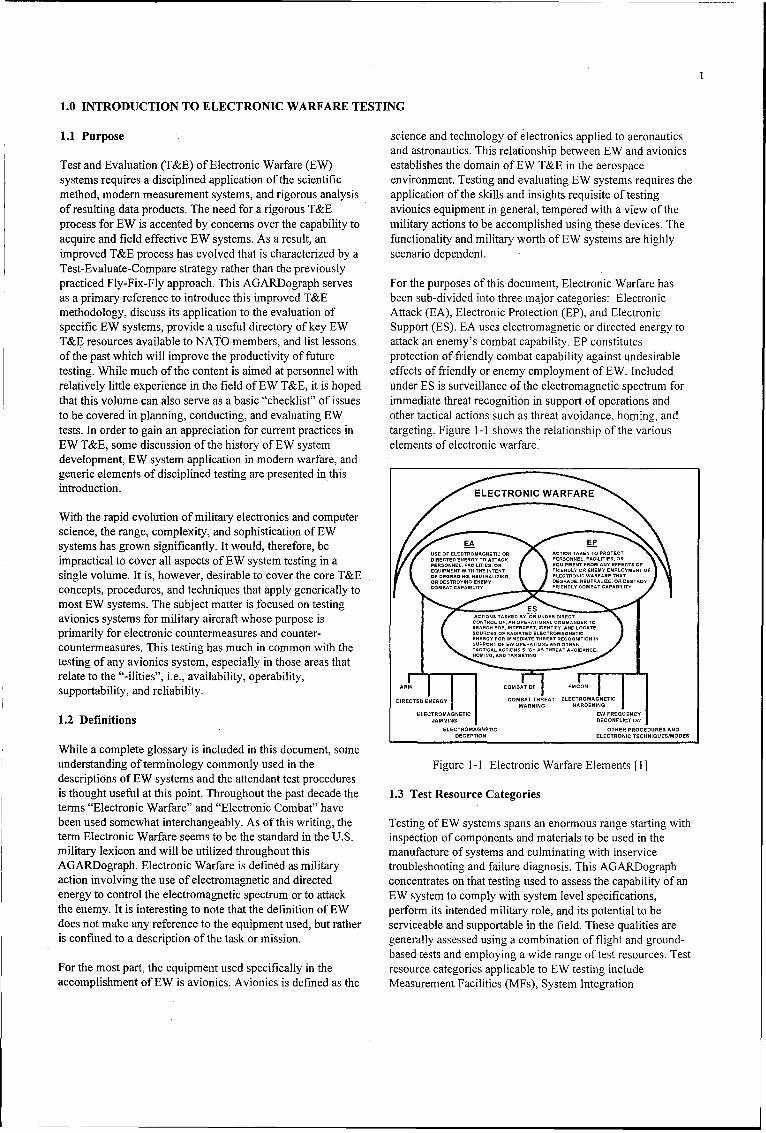
Test and Evaluation (T&E) of Electronic Warfare (EW) establishes the domain of EW T&E in the aerospacesystems requires a disciplined application of the scientific environment. Testing and evaluating EW systems requires themethod, modem measurement systems, and rigorous analysis application of the skills and insights requisite of testingof resulting data products. The need for a rigorous T&E avionics equipment in general, tempered with a view of theprocess for EW is accented by concerns over the capability to military actions to be accomplished using these devices. Theacquire and field effective EW systems. As a result, an functionality and military worth of EW systems are highlyimproved T&E process has evolved that is characterized by a scenario dependent.Test-Evaluate-Compare strategy rather than the previouslypracticed Fly-Fix-Fly approach. This AGARDograph serves For the purposes of this document, Electronic Warfare hasas a primary reference to introduce this improved T&E been sub-divided into three major categories: Electronicmethodology, discuss its application to the evaluation of Attack (EA), Electronic Protection (EP), and Electronicspecific EW systems, provide a useful directory of key EW Support (ES). EA uses electromagnetic or directed energy toT&E resources available to NATO members, and list lessons attack an enemy's combat capability. EP constitutesof the past which will improve the productivity of future protection of friendly combat capability against undesirabletesting. While much of the content is aimed at personnel with effects of friendly or enemy employment of EW. Includedrelatively little experience in the field of EW T&E, it is hoped under ES is surveillance of the electromagnetic spectrum forthat this volume can also serve as a basic "checklist" of issues immediate threat recognition in support of operations andto be covered in planning, conducting, and evaluating EW other tactical actions such as threat avoidance, homing, andtests. In order to gain an appreciation for current practices in targeting. Figure 1-1 shows the relationship of the variousEW T&E, some discussion of the history of EW system elements of electronic warfare.development, EW system application in modem warfare, andgeneric elements of disciplined testing are presented in thisintroduction. ELECTRONIC WARFARE
With the rapid evolution of military electronics and computerscience, the range, complexity, and sophistication of EWsystems has grown significantly. It would, therefore, be EA ED
impractical to cover all aspects of EW system testing in a PGREcTERDEGY TOAKO CTIES, ORpESONEL, FACILITIESR EQUIPMENT FROM ANY EFFECTS OF
single volume. It is, however, desirable to cover the core T&EO FRIENDLY DR ENEMY EMPLOY OFOR DEGSRADING, ENEUTALY IG DEGRADE,' NEUTRALIE, OR DESTROY
concepts, procedures, and techniques that apply generically to CMA AAIIYFINL OSTCWBLTmost EW systems. The subject matter is focused on testing ESavionics systems for military aircraft whose purpose is .............................
CONTROL OF, AN OPERATIONAL COMMANDER TO
primarily for electronic countermeasures and counter- EOESSSFOR RADIEATED TELTECCTROANETICSINcountermeasures. This testing has much in common with the SPRTICAL OEW OPERATION•SI•A .A.R .
testing of any avionics system , especially in those areas that HOIG AND.........G
relate to the "-ilities", i.e., availability, operability,supportability, and reliability. ARM COMBAT OF COCOS
DIRECTED ENERGY COMBAT THREAT ELECTROMAGNETIC
WARRING HARDENINGELECTROMAGNETIC EW FRED UENCY
1.2 Definitions ....... TOELECTROMAGNETIC OTHER PROCEDURES AND
DECEPTION ELECTRONIC TECINIQUESIMODES
While a complete glossary is included in this document, someunderstanding of terminology commonly used in the Figure 1-1 Electronic Warfare Elements [ ]descriptions of EW systems and the attendant test proceduresis thought useful at this point. Throughout the past decade the 1.3 Test Resource Categoriesterms "Electronic Warfare" and "Electronic Combat" havebeen used somewhat interchangeably. As of this writing, the Testing of EW systems spans an enormous range starting withterm Electronic Warfare seems to be the standard in the U.S. inspection of components and materials to be used in themilitary lexicon and will be utilized throughout this manufacture of systems and culminating with inserviceAGARDograph. Electronic Warfare is defined as military troubleshooting and failure diagnosis. This AGARDographaction involving the use of electromagnetic and directed concentrates on that testing used to assess the capability of anenergy to control the electromagnetic spectrum or to attack EW system to comply with system level specifications,the enemy. It is interesting to note that the definition of EW perform its intended military role, and its potential to bedoes not make any reference to the equipment used, but rather serviceable and supportable in the field. These qualities areis confined to a description of the task or mission, generally assessed using a combination of flight and ground-
based tests and employing a wide range of test resources. TestFor the most part, the equipment used specifically in the resource categories applicable to EW testing includeaccomplishment of EW is avionics. Avionics is defined as the Measurement Facilities (MFs), System Integration
2
Laboratories (SILs), Hardware-in-the-Loop (HITL) facilities,Installed System Test Facilities (ISTFs), and Open-AirRanges (OARs). A sixth resource category of growingimportance is Modeling and Simulation (M&S).
It is tempting to equate "types of tests" with specific test q .- )facilities. For instance OARs provide an environment whereaircraft can be operated in their intended flight regimes, butcan also often support testing of systems installed in theaircraft while the vehicle is on the ground. In this scenario, we MODUNG-&SIMULAnON
would be conducting an "installed system" test type using anOAR resource category. Large anechoic chambers, capable ofholding an actual aircraft, are frequently classed as "Installed
SYSTEM RDWGRE- INTALLED OPEN
System Test Facilities." While this categorization is INTEGRATON EI,.SE.LOOP SYSTEM TEST MR
applicable, it does not convey the full range of applications LABORoR FALI FACLMEs
for which an ISTF may be suitable. Frequently, ISTFs areused to support HITL tests, integration activities, and
simulations. As a result, we may arrive at inaccurate or MEASUREMENT FACIUTiES
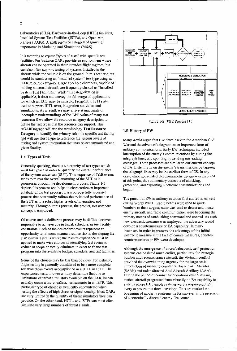
incomplete understandings of the T&E value of many testresources if we allow the resource category description to Figure 1-2 T&E Process [I]define the test types that the resource can support. ThisAGARDograph will use the terminology Test Resource 1.5 History of EWCategory to identify the primary role of a specific test facilityand will use Test Type to reference the various levels of Many would argue that EW dates back to the American Civiltesting and system integration that may be accommodated at a War and the advent of telegraph as an important form ofgiven facility, military communications. Early EW techniques included
1.4 Types of Tests interruption of the enemy's communications by cutting thetelegraph lines, and spoofing by sending misleadingmessages. These processes are similar to our current concept
Generally speaking, there is a hierarchy of test types which of EA. Listening in on the enemy's transmissions by tappingmust take place in order to quantify the overall performance the telegraph lines may be the earliest form of ES. In anyof the system under test (SUT). This sequence of T&E events case, while no radiated electromagnetic energy was involvedtends to mirror the overall maturing of the SUT as it at this point, the rudimentary concepts of attacking,progresses through the development process. Figure 1-2 protecting, and exploiting electronic communications haddepicts this process and helps to characterize an important begun.attribute of the test process; it is a purposefully recursiveprocess that continually refines the estimated performance of The pursuit of EW in military aviation first started in earnestthe SUT as it reaches higher levels of integration and during World War II. Radio beams were used to guidematurity. Throughout this process, the predict, test compare bombers to their targets, radar was used to detect and locateconcept is employed. enemy aircraft, and radio communication were becoming the
primary means of establishing command and control. As eachOf course such a deliberate process may be difficult or even new electronic measure was employed, the adversary would
impossible to achieve due to fiscal, schedule, or test facility develop a countermeasure or EA capability. In many
constraints. Each of the desired test events represent an instances, in order to preserve the advantage of the initial
opportunity to, in some manner, reduce risk in developing the electronic measure in the face of countermeasures, counter-
EW system. Here is where the tester's experience must be countermeasures or EPs were developed.
applied to make wise choices in identifying test events to
reduce in scope or totally eliminate in order to fit the test Although the emergence of aircraft electronic self-protectionprogram into the available budget, schedule, and test facilities, systems can be dated much earlier, particularly for strategic
bomber and reconnaissance aircraft, the Vietnam conflictSome of the choices may be less than obvious. For instance, provided the overwhelming urgency for the large scaleflight testing is generally considered to be a more complete introduction of means to counter Surface-to-Air Missilestest than those events accomplished in a HITL or ISTF. The (SAMs) and radar-directed Anti-Aircraft Artillery (AAA).experienced tester, however, may determine that.due to (As n aa-ietdAt-icatAtley(A)experatiencedf threster, however, mayide ine that d he t n During the period of combat air operations over Vietnam,limitations of threat simulators available on the OAR, he can tactical aircraft progressed from virtually no EA capability to
actually create a more realistic test scenario in an ISTF. This tatus where p ablesse m v ir E ment toparticular type of choice is frequently encountered whena requirement for
partculr tye o chice s fequetlyencunteed henevery exposure to a threat envelope. This era marked thetesting the effects of high threat or signal density. Most OARs eeyepsr oatra neoe hseamre htres ery effects of thequantighof threat orsinsimatyorsthy OaRS beginning of modern requirements for survival in the presenceare very limited in the quantity of threat simulators they can of electronically directed enemy fire control.
provide. On the other hand, HITLs and ISTFs can most often
simulate very large numbers of threat signals.

3
1.6 EW System Application In Warfare enough to break range or velocity lock in a tracking radar. Ifthe acquisition radar still has valid angle information to
As discussed earlier in this chapter, EW can be broken down provide to the weapon, the target can be quickly re-acquired.into three primary divisions; EA, EP, and ES. In order to Several BA techniques can be used in concert to completelybetter understand the test requirements, a brief overview of mislead the acquisition system, thus preventing the targeteach of these primary divisions is given below. It is not the from being relocated in time to re-aim the weapon.intent of this publication to fully describe the role of EW inmilitary actions or to provide a detailed analysis of specific 1.6.2 Overview of EPEW techniques.
EP is that action taken to negate the effects of either enemy or1.6.1 Overview of EA friendly BA that would degrade, neutralize, or destroy
friendly combat capability. EP techniques tend to be the resultEA is the use of electromagnetic or directed energy to attack of developments of EA capabilities. Most EP techniques arepersonnel, facilities, or equipment. There are four basic sub- defined in relation to how they counter a specific BA threat.divisions of BA; jamming, deception, anti-radiation missiles Usually, the EP technique is some improvement in the sensor(ARMs), and directed energy weapons. Jamming is generally design that counteracts the effect of a specific EA technique;defined as deliberate radiation, re-radiation, or reflection of therefore, it is difficult to understand the purpose of a specificenergy for the purpose of preventing or reducing an enemy's EP technique without knowing the BA technique that it iseffective use of the electromagnetic spectrum. With recent designed to counteract.advances in technology and more frequent use of spectraoutside the electromagnetic range, this definition can be Usually, the design requirements of a system that operates in aextended to cover similar action against infrared (IR), jamming environment will exceed the requirements of aultraviolet (UV), and electro-optical systems. similar system designed to operate only in a friendly
environment. For example, a radar receiver designed for 'useJamming is the most prevalent form of BA and has three in a friendly environment can tolerate relatively wide bandmajor sub-divisions; self-protection, escort, and stand-offt In frequency response with only minimal degradation inself-protection jamming, the same vehicle being targeted by performance. A similar receiver designed for use in athe enemy radar or sensor system carries the BA system. jamming environment would require narrow band frequencyUsually, this form of jamming has the disadvantage of being response to prevent skirt jamming.limited in the amount of effective radiated power (BRP), buthas the advantage of being able to inject BA in the main lobe The BP designer may utilize sophisticated transmittedof the enemy system. In escort jamming, the escort vehicle waveforms and receiver processing that will make deception(the vehicle carrying the BA system) is often dedicated solely jamming difficult. This forces the enemy to use high-power,to BA, thus providing for more available ERP and having the brute-force noise jamming. The EP designer can then useadvantage of injecting interference in the main lobe of the frequency hopping or multiple simultaneously transmittedenemy system as well as the sidelobes. In stand-off jamming, frequencies so that the enemy must broaden the bandwidth ofthe BA platform is at a long range from the enemy defenses his jamming. This causes the enemy jammer to diffuse itsand is usually in the sidelobe of the enemy radar, but it too energy over a wide bandwidth, thus reducing the effectivenesscan provide more ERP by being dedicated to BA. of the BA. A true cat and mouse game between EA and EP
designers results.There are basically two types of enemy radar that must bejammed by BA. The first is surveillance, or search radar, used 1.6.3 Overview of ESto locate the position of a target within a large coveragevolume. A specific type of surveillance radar of interest to the ES is that division of BW concerned with the ability to searchBA designer is the acquisition radar used to locate targets for for, intercept, identify, and locate sources of radiatedfire control systems. The second type of radar to be jammed is electromagnetic energy. ES is used in support of tacticalthe tracking radar that is usually given high priority in the operations for situational awareness, threat avoidance,hierarchy of BA threats because it is associated with the homing, and targeting. Onboard radar warning and missileterminal phases of a weapon guidance system. BA techniques warning receivers, as well as many off-board surveillanceare used to disrupt or break the threat's range, velocity, or systems, are considered elements of ES.angle tracking capability and force the acquisition radar torelocate the target and re-aim the weapon - a process which 1.7 EW Test and Evaluation Processcould provide the target the time to pass harmlessly throughthe threat's engagement envelope. An overall plan or process is required to conduct efficient,
cost effective T&E. The EW T&B process presented here isPassive techniques are also used to avoid, degrade, or deceive intended to be universal, for use by all participants involvedan adversary's sensor systems. Chaff, passive decoys, and in weapons acquisition and development. Its use implements asignature reduction are all elements of BA. predict-test-compare philosophy and stresses adequate ground
testing before implementing a flight testing methodology.Several jamming techniques are often used in conjunction to This process is applicable in developmental, operational, andconfuse the enemy radar system. For example, it may not be other phases of military systems testing. If you are starting to
4
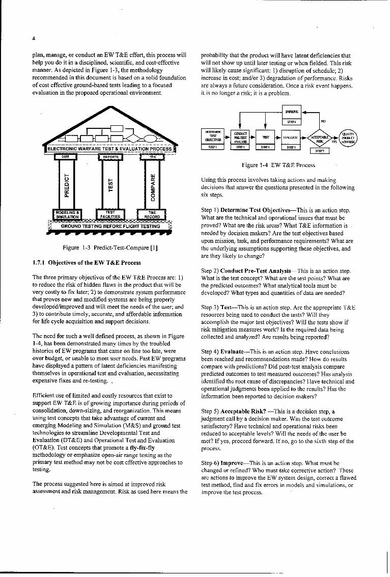
plan, manage, or conduct an EW T&E effort, this process will probability that the product will have latent deficiencies thathelp you do it in a disciplined, scientific, and cost-effective will not show up until later testing or when fielded. This riskmanner. As depicted in Figure 1-3, the methodology will liely cause significant: 1) disruption of schedule; 2)recommended in this document is based on a solid foundation increase in cost; and/or 3) degradation of performance. Risksof cost effective ground-based tests leading to a focused are always a future consideration. Once a risk event happens,evaluation in the proposed operational environment, it is no longer a risk; it is a problem.
SI1I'(
OBECN RIrSK SELECTRONIC WARFARE TEST & EVALUATION PROCESS 4. Slfl'3
Figure 1-4 EW T&E Process
0ý Using this process involves taking actions and making(L decisions that answer the questions presented in the following
0. 0 six steps.
MOELNG 1 TES T&E 1Step 1) Determine Test Objectives-This is an action step.SIUAIO AILTE RECORD What are the technical and operational issues that must be
GROUND TESTING BEFORE FLIGHT TESTING proved? What are the risk areas? What T&E information is__ _ - -needed by decision makers? Are the test objectives based
upon mission, task, and performance requirements? What areFigure 1-3 Predict-Test-Compare [1] the underlying assumptions supporting these objectives, and
are they likely to change?1.7.1 Objectives of the EW T&E Process
Step 2) Conduct Pre-Test Analysis-This is an action step.The three primary objectives of the EW T&E Process are: 1) What is the test concept? What are the test points? What areto reduce the risk of hidden flaws in the product that will be the predicted outcomes? What analytical tools must bevery costly to fix later; 2) to demonstrate system performance developed? What types and quantities of data are needed?that proves new and modified systems are being properlydeveloped/improved and will meet the needs of the user; and Step 3) Test-This is an action step. Are the appropriate T&E3) to contribute timely, accurate, and affordable information resources being used to conduct the tests? Will theyfor life cycle acquisition and support decisions, accomplish the major test objectives? Will the tests show if
risk mitigation measures work? Is the required data beingThe need for such a well defined process, as shown in Figure collected and analyzed? Are results being reported?1-4, has been demonstrated many times by the troubledhistories of EW programs that came on line too late, were Step 4) Evaluate-This is an action step. Have conclusionsover budget, or unable to meet user needs. Past EW programs been reached 'and recommendations made? How do resultshave displayed a pattern of latent deficiencies manifesting compare with predictions? Did post-test analysis comparethemselves in operational test and evaluation, necessitating predicted outcomes to test measured outcomes? H-as analysisexpensive fixes and re-testing. ,identified the root cause of discrepancies? Have technical and
operational judgments been applied to the results? Has theEfficient use of limited and costly resources that exist to information been reported to decision makers?support EW T&E is of growing importance during periods ofconsolidation, down-sizing, and reorganization. This means Step 5) Acceptable Risk? -This is a decision step, ausing test concepts that take advantage of current and judgment call by a decision maker. Was the test outcomeemerging Modeling and Simulation (M&S) and ground test satisfactory? Have technical and operational risks beentechnologies to streamline Developmental Test and reduced to acceptable levels? Will the needs of the user beEvaluation (DT&E) and Operational Test and Evaluation met? If yes, proceed forward. If no, go to the sixth step of the(OT&E). Test concepts that promote a fly-fix-fly process.methodology or emphasize open-air range testing as theprimary test method may not be cost effective approaches to Step 6) Improve-This is an action step. What must betesting. changed or refined? Who must take corrective action? These
are actions to improve the EW system design, correct a flawedThe process suggested here is aimed at improved risk test method, find and fix errors in models and simulations, orassessment and risk management. Risk as used here means the improve the test process.

5
1.7.2 Integrated Processes 1.7.4 Data Reduction
The EW T&E Process supports and must be integrated with The test itself only provides data, observations, andthe more complex Acquisition Process. The EW T&E Process information to be subsequently evaluated. The bridge betweeninterfaces with the system acquisition process as shown in testing and evaluation is "data reduction." Often this step isFigure 1-5. The user defines system requirements and deploys thought to be a simple act of feeding data to the computersthe system after development. The program manager controls and waiting for the output to appear on the engineer's desk.program specifications, design, and production. The Test Experienced testers know differently; they are fully aware thatOrganization is responsible for detailed test planning, factors such as selection of data, editing of "wild points," andconduct, evaluation, and reporting. Information must be determination of statistical processes to be applied to the datadeveloped and shared between user, tester, and acquisition can have a major effect on the outcome of the evaluation. Acommunities. EW testing requires an integrated effort thorough understanding of experimental statistics is a(teamwork) to get a quality product with low risk that meets prerequisite for the successful evaluation of any EW system.user needs.
1.7.5 Examples
SYSTEM TEST TSACQUISI~0N ANALYSIS TETFigure 1-6 contains examples of how the six resource
Pre-Test Modeling & categories support the different kinds of EW testing required.Requirements Test Planning Simulation The annex of this document provides summary informationSpecification Predict Results *Measurement on specific facilities representative of those typically used.
DesignFacilitiesDesignSystem
Produce Integration 1.8 EW T&E Resource UtilizationDeploy Laboratories
Sustain - Hardware-in-the-Post-Test Loop Facilities Recognizing that threat system availability, threat density, and
Retire . nlz aa *Installed SystemsExtaplyz ateaetFclte closed-loop effectiveness may dictate resources used, theCTP and MOE Open Air Ranges following considerations apply.
Figure 1-5 Integrated Effort [1]1.1ReaieCs
1.7. Mor Prductve Figh TesingIn general, the cost per test becomes more expensive as the1.7. Mor Prductve Figh Tesingtesting moves to the right as shown notionally in Figure 1-7.
The W TE Poces relacs te fl-fi-fl tes phlosphy The use of models, simulations, and ground testing can reduce
wth he EW r T& ientProcs replacsthefyfxfytest-opr philosophy. overall test costs since open-air flight tests are the most costly.
withthgoreu scientii peittest -c s oeeompre phdduinflosohy. In general, the cost per test becomes more expensive as the
Rgrugrudtesting is doneitbeforehandnduring flightte.Siuaonar testing moves to the right, as shown notionally in Figure 1-7.
tsestn to prermict ahghon confdec flight test. rslsatseimuaicointsar The use of models, simulations, and ground testing can reduce
use toe pereditorounde andeoe flight tesesuts arethseciin pit overall test costs since open-air flight tests are the most costly.
conducted, differences analyzed, and if appropriate, 1.8.2 Relative Usedeficiencies corrected. Once ground testing demonstrates thatperformance is as predicted, flight testing can begin, using the Due to the complexity of LW systems and threat interactions,predict-test-compare philosophy with deficiencies modeling and simulation can be used in a wide range ofinvestigated on the ground and necessary model updates progressively more rigorous ground and flight test activities.accomplished. Verification of the ground test data at the Figure 1-8, also notional, shows that modeling and simulationproper envelope points means flight testing will not have to be and measurement facilities are used throughout the testdone throughout the entire performance envelope. This spectrum. It also shows how the number of trials/tests shouldapproach amounts to flight testing smarter, not harder, decrease as the testing proceeds to the right through the
categories.
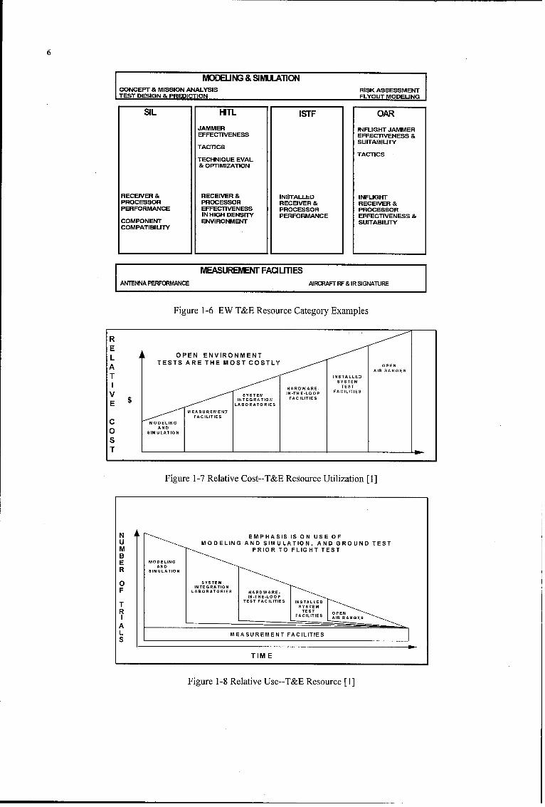
6
MODBJNG & SIMULATIONCONCEPT & MISSION ANALYSIS RISK ASSESSMENTSTEST DESIGN & PREDICTION FLYOUT MODELING
SIL HITL IsTF OAR
JAMMER INFUGHT JAMMEREFFECTIVENESS EFFECTIVENESS &
SUITABILITYTACTICS
TACTICSTECHNIQUE EVAL& OPTIMIZATION
RECEIVER & RECEIVER & INSTALLED INFUGHTPROCESSOR PROCESSOR RECEIVER & RECEIVER &PERFORMANCE EFFECTIVENESS PROCESSOR PROCESSOR
IN HIGH DENSITY PERFORMANCE EFFECTIVENESS &COMPONENT ENVIRONMENT SUITABILITYCOMPATIBILITY
I ~MEASUREIENT FACIUTIES
ANTENNA PERFORMANCE AIRCRAFT RF & IR SIGNATURE
Figure 1-6 EW T&E Resource Category Examples
REL OPEN ENVIRONMENT
TESTS ARE THE MOST COSTLY • OPENAISALE AIR RANGES
TSYSTEM
HARDWARE- TEST
V SYSTEM I N-TH E-LOOP FACILITIES
E $INTEGR AT1.ON FACILITIESE LABORATORIESSMEASUREMENTC MODELING
AND0SIM ULATION
sT ON
Figure 1-7 Relative Cost--T&E Resource Utilization [1]
N EMPHASIS IS ON USE OFU MODELING AND SIMULATION, AND GROUND TESTM PRIOR TO FLIGHT TEST
BE MODELING
R IULATION
O SYSTEM0 ~INTSEGRATION
F LABORATORIES HARDWARE.
T
AL MEASUREMENT FACILITIES I
TIME
Figure 1-8 Relative Use--T&E Resource [1]

7
1.9 Safety Considerations Test plans come in a multitude of forms and formats; eachcreated to ensure a specific requirement or group of
No introduction to EW test and evaluation would be complete requirements are satisfied in the most complete and efficientwithout some mention of safety. Specific safety procedures manner possible. Clearly, a complete description of the manymust be developed and observed for each type of test in each forms of test plans is well beyond the scope of this document;type of facility. Some basic considerations should be obvious, however, we will discuss some of the key attributes andbut are all too often overlooked, motivations for good test planning.
1.9.1 Electrical Shock Hazard 1.10.1 Cost and Test Budget
Many EW systems utilize high power transmitters requiring Few, if any, test programs have unlimited funding and sohigh voltage excitation for the final output stages. In addition, budgeting for each test event is critical. It is difficult tonearly all EW systems make use of either I11 5VAC or 28 accurately predict the cost of an unplanned or poorly plannedVDC electrical power for operation. While these power activity. Early in the program when test events are not clearlysources are generally well protected when the system is specified, the budgeted cost for testing will likewise be only ainstalled in its operational configuration, they may be exposed rough estimate. The sooner more complete test planning isand easily contacted during test activities. This is particularly accomplished, the sooner the test budget can be accuratelytrue in the HITL and SIL environment, determined. Generally, as the program progresses, the
potential for acquiring additional funding is reduced. Poor1.9.2 Radiation Hazard budgeting at the beginning of the program will nearly always
result in severe constraints on test execution and failure of theAs metioned in the previous paragraph, it is common to find test effort to deliver the information required.high power RE transmitters in Electronic Attack systems.Effects of human exposure to high intensity RE fields can 1.10.2 Schedulevery from minor reddening of the skin to severe andpermanent damage to internal organs. High power radiation As with the budget, the schedule for testing is affirmedcan also cause equipment damage. The most common through the development of detailed test plans. Test facilitiesopportunity for such damage is in anechoic chambers. The needed to accomplish the desired testing may have very fullradar absorbent material (RAM) used in these chambers will schedules. Your chances of having access to the facilities youabsorb rather than reflect the RE energy from the systems in need, when you need them, is greatly increased if detailed testoperation. The absorption of energy causes heating of the planning is accomplished early. The schedule tends to be aRAM. As a result, power levels must be carefully monitored major driver for the budget. Inaccurate schedule projectionsand constrained to levels below that at which the heating of will generally lead to budget discontinuities and, in the end,the RAM will result in a fire. Radiation hazards can exist in failure of the test program to deliver the required information.all test environments but are most frequently encountered inthe ISTF and OAR testing phases. 1.10.3 Test Efficiency
1.9.3 Pyrotechnic Hazards Accomplishment of test events in the correct sequence cansubstantially reduce the amount of retest or regression testing
EW expendables such as chaff and flares rely on pyrotechnic required. Again, test planning is your primary tool to(explosive) devices for ejection. One can easily imagine the understand and analyze the best sequence of events. It is alsoresults of an inadvertent firing of these devices during ground the process where experienced testers accomplish the trademaintenance or test operations. Also, EW pods carried on studies to assess how programmatic risk will be effected bycenterline or wing stations of aircraft are frequently elimination or insertion of test events.jettisonable. Unintended firing of the explosive charges thatinitiate the jettison sequence may result in both personnel 1.10.4 The Bottom Lineinjury and equipment damage. These pyrotechnic hazards aremost likely to occur during ground test or preparation for It is the test planning process that permits a logical sequenceflight test in the OAR testing phase. of test activities with reasonable expectations at each stage.
Data reduction and analysis, safety, and certainly a1.10 The Test Plan meaningful evaluation are all virtually useless (and probably
impossible) without a carefully developed test plan.All test activities require careful planning to be successful.While test planning is not unique to EW, a mention of thiselement is made here for completeness.

8
9
2.0 TEST AND EVALUATION OF ELECTRONIC SUPPORT SYSTEMS
2.1 General Considerations also be measured such that radar scan information can bederived. The amplitude of the signal can also be used to
Electronic Support (ES) is that division of Electronic Warfare estimate the radar's range from the aircraft.(EW) concerned with the ability to search for, intercept,identify, and locate sources of radiated electromagnetic Through an iterative process of sorting the received signals inenergy. ES is used in tactical operations for situational frequency or at least frequency band, and then subtracting theawareness, threat avoidance, homing, and targeting. On-board time of arrival of one pulse from the next, the time betweenradar warning, laser warning, and missile warning receivers, pulses can be found. This is termed the pulse repetitionas well as many off-board surveillance systems, are interval or PRI. A CW signal will not have a PRI but isconsidered elements of ES. simply sorted as a CW. When data consisting of frequency,
pulse width, PRI or CW, and scan are collated about one2.2 Radar Warning Receivers (RWRs) received RE signal, it is compared to a list of the parameters
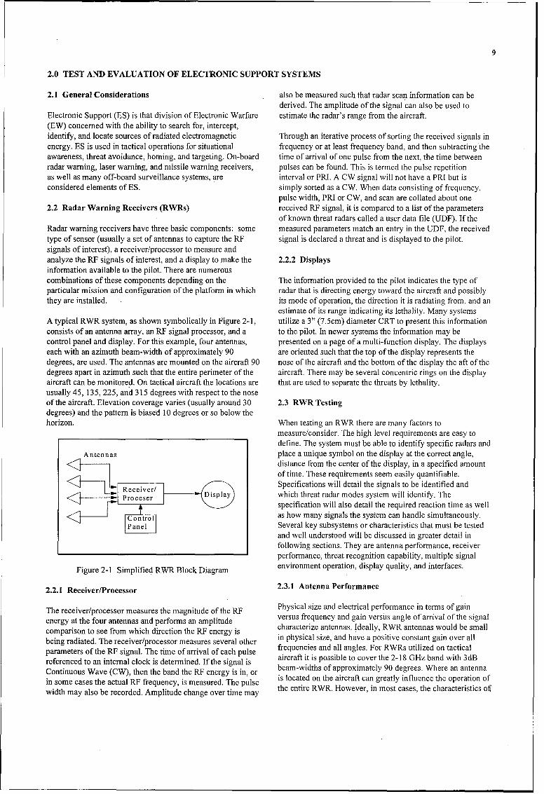
of known threat radars called a user data file (UDF). If theRadar warning receivers have three basic components: some measured parameters match an entry in the UDF, the receivedtype of sensor (usually a set of antennas to capture the RE signal is declared a threat and is displayed to the pilot.signals of interest), a receiver/processor to measure andanalyze the RE signals of interest, and a display to make the 2.2.2 Displaysinformation available to the pilot. There are numerouscombinations of these components depending on the The information provided to the pilot indicates the type ofparticular mission and configuration of the platformn in which radar that is directing energy toward the aircraft and possiblythey are installed. its mode of operation, the direction it is radiating from, and an
estimate of its range indicating its lethality. Many systemsA typical RWR system, as shown symbolically in Figure 2-1, utilize a 3" (7.5cm) diameter CRT to present this informrationconsists of an antenna array, an RE signal processor, and a to the pilot. In newer systems the information may becontrol panel and display. For this example, four antennas, presented on a page of a multi-function display. The displayseach with an azimuth beam-width of approximately 90 are oriented such that the top of the display represents thedegrees, are used. The antennas are mounted on the aircraft 90 nose of the aircraft and the bottom of the display the aft of thedegrees apart in azimuth such that the entire perimeter of the aircraft. There may be several concentric rings on the displayaircraft can be monitored. On tactical aircraft the locations are that are used to separate the threats by lethality.usually 45, 135, 225, and 315 degrees with respect to the noseof the aircraft. Elevation coverage varies (usually around 30 2.3 RWR Testingdegrees) and the pattern is biased 10 degrees or so below thehorizon. When testing an RWR there are many factors to
measure/consider. The high level requirements are easy todefine. The system must be able to identify specific radars and
Antennasplace a unique symbol on the display at the correct angle,distance from the center of the display, in a specified amountof time. These requirements seem easily quantifiable.
Recever/Specifications will detail the signals to be identified and
Proceer Diplaywhich threat radar modes system will identify. Thespecification will also detail the required reaction time as well
Controlas how many signals the system can handle simultaneously.PanelSeveral key subsystems or characteristics that must be tested
and well understood will be discussed in greater detail infollowing sections. They are antenna performance, receiverperformance, threat recognition capability, multiple signal
Figure 2-1 Simplified RWIR Block Diagram environment operation, display quality, and interfaces.
2.2.1 Receiver/Processor 2.3.1 Antenna Performance
The receiver/processor measures the magnitude of the RE Physical size and electrical performance in terms of gainenery a th for atenas ad prfoms n apliudeversus frequency and gain versus angle of arrival of the signal
comparison to see from which direction the RE energy is characterize antennas. Ideally, RWR antennas would be small
being radiated. The receiver/processor measures several other in physical size, and have a positive constant gain over allpaaeesof the RE signal. The time of arrival of each pulse freq Iuencies and all angles. For RWRs utilized on tactical
referenced to an internal clock is determined. If the signal is aicfttispsbltoovrhe21 zbndwh3B
Continuous Wave (CW), then the band the RF energy is in, or beam-widths of approximately 90 degrees. Where an antennain sme ase th acualRF requncy ismeaure. Te plse is located on the aircraft can greatly influence the operation of
width may also be recorded. Amplitude change over time may teetr W .Hwvr nms aetecaatrsiso
to
the antenna are chosen to minimize the change in RCS on the it is designed to detect and viewing the response on thehost platformn. Computer modeling is used to design antennas display. During these tests the display is monitored to verifyand antenna placement. Actual antenna performance is first key characteristics. The time required to process and displaydetermined at a measurement facility (MF) or antenna range threat warnings, correct symbology, and proper location ofdesigned specifically for the purpose of measuring antenna symbology can be observed. Generations of unwarrantedperformance. Installed antenna performance is then symbols (false alarms) and missed detections are alsocharacterized at an Installed System Test Facility (ISTF) or observed. The entire UDF needs to be verified by testing atMF. the extremes of all the parameters. Initially, testing is
conducted using only one signal at a time. Testing continues2.3.2 Receiver Performance to increase in complexity when a multiple signal environment
is used.Receiver performance is critical to the overall performance ofthe RWIR system because the quality of the receiver output 2.3.4 Multiple Signal Environment Operationdetermines what data the processor has to work with. It isdifficult to talk generically about receivers because almost RWR performance in a dynamic, multiple radar environmentevery receiver is unique to meet the specific needs of the is the only way to determine just how well the system willsystem it was designed for. There are, however, a few perform in its intended environment. However, when acommon measurements that need to be understood. Receiver multiple signal environment is encountered there are factorssensitivity is a key parameter because it gives a good idea that can only be measured qualitatively. Dense signalabout how well low power signals are measured. The most environments are frequently generated using open-loop radarcommon measurement of receiver sensitivity is minimum simulators when testing is performed on the ground and bydetectable signal (MDS). MDS is the smallest power level pointing multiple radars toward the aircraft during flight test.value of an input signal that the receiver can detect. It must be The quality of the simulators can greatly affect the types ofmade clear that the receiver is able to process the signal and tests that can be performed on the RWR.not merely detect it. The operating range of the receiver is thefrequencies where the receiver meets its MDS specification 2.3.5 Display Qualityvalue. How well a receiver can resolve two signals closetogether in frequency (selectivity) is also very important. If How "smoothly" a display changes when threats appear orthe receiver is able to provide the processor more accurate change angle is very important to a pilot's ability to interpretfrequency values, it will make it easier to distinguish between the data being presented. How quickly the RWIR will updateradars that are operating at nearly the same frequency. the display to show relative position and priority changes canDifferent types of receivers operate differently in high signal also be critical to the pilot's situational awareness. Thesedensities and with simultaneous signals. The better the features are difficult to analyze and usually not detailed in areceiver operates in a high-density environment, the easier it specification. Operational testing frequently reveals theis for the processor to properly identify and classify received overall suitability of the display.signals.
2.3.6 Interfaces2.3.3 Threat Recognition Capability
The RWR may be integrated with other on-board avionics. ItProbably one of the most visible measures of merit is how may share information with the aircraft's radar, the jammingwell an RWR can uniquely identify the radars it is system to help each system resolve ambiguities, and be usedprogrammed to display. Two features that greatly effect how in the decision criteria on whether or not an expendable willwell an RWvR can do this are the detail in the user data file be utilized. Blanking schemes from the jammer, the aircraft's(UDF) and the measurement capabilities of the receiver. The radar, or the radar altimeter may degrade the performance ofUDF contains parameters to characterize the threats that are to the RWR. All these interfaces must be tested singularly andbe displayed or intentionally not displayed. Mission data file then in combination.(MDF) is another name for these data. The parameters usuallyfound in the UDF are: radar frequency operating range, pulse 2.3.7 Ground Testingor CW operation, pulse width range, pulse repetition interval(PRI) range, scan type, and scan frequency range. These are There are many different ground tests during the developmentjust the basic parameters. Each system will have unique of an RWR system. Actual antenna performance should beparameters to optimize identification accuracy and response obtained at a measurement facility built to perform that typetime. The RWR must be able to identify the threat over its of testing. An accurate way of positioning the antenna andentire operating range of the modes it has been programmed measuring the resulting angle between source and antenna isto respond to. RWvRs are usually only programmed to display important as well as spectrum analysis capabilities and.the target tracking modes of threat radars but may have other computer processing capability to compute gain values andmodes of the radars in their UDFs to make sorting easier. The present data. Parametric testing, as discussed in Section 2.3.2,target track modes are the only ones displayed because they to determine the receiver performance should beare the only ones that can lead to the launching of a missile or accomplished during ground testing for two reasons. First, itdirect gun fire toward the aircraft. Threat recognition is tested is easier to access the hardware to conduct the tests, andby stimulating the system under test with the radar signatures second, it avoids waste expensive flight time with an
immature receiver. Hardware-in-the-Loop (HITL) testing is a 2.4 Missile Warning Systemslarge part of ground testing and may be the first time theRWR system has seen a dense threat environment due to Passively guided surface-to-air missiles are a significant threatlimited simulation ability at the contractor facility. In the to low-slow flying aircraft. These threats have accounted forHITL, threat recognition, display quality, and multiple signal the majority of aircraft losses in combat over the last 20 years.environment capabilities are tested. Testing begins by Passive threat warning systems, usually referred to as Missilestimulating the RWVR system with a single threat emitter to Warning Sets (MWSs), are now operational on helicoptersdetermine the one-on-one receiver operation. After and transport aircraft.confidence is gained that the system is performing well oneon one, multiple signal environments are tested. An ISTF is Passive threat warning systems are designed to detect thewhere the RWR system is first tested in the actual platform it electromagnetic radiation from the rocket motor of the threatwill be used. This is the best place to perform interface testing missile. Detection can occur due to the rocket motor ignitionbecause all the various avionics boxes are functioning (launch detection) or by detection of the burning motor duringtogether for the first time. fly-out (in-flight detection). Most modern systems employ
sensors that use a combination of the two types of detection.2.3.8 Flight Testing The problem to the passive warning system is to differentiate
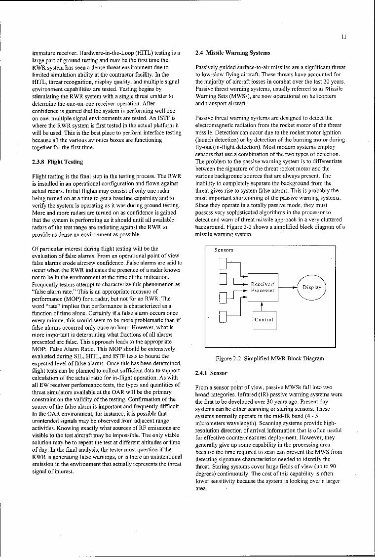
between the signature of the threat rocket motor and theFlight testing is the final step in the testing process. The RWR various background sources that are always present. Theis installed in an operational configuration and flown against inability to completely separate the background from theactual radars. Initial flights may consist of only one radar threat gives rise to system false alarms. This is probably thebeing turned on at a time to get a baseline capability and to most important shortcoming of the passive warning systems.verify' the system is operating as it was during ground testing. Since they operate in a totally passive mode, they mustMore and more radars are turned on as confidence is gained possess very sophisticated algorithms in the processor tothat the system is performing as it should until all available detect and warn of threat missile approach in a very clutteredradars of the test range are radiating against the RWR to background. Figure 2-2 shows a simplified block diagram of aprovide as dense an environment as possible. missile warning system.
Of particular interest during flight testing will be the Sensorsevaluation of false alarms. From an operational point of viewfalse alarms erode aircrew confidence. False alarms are said tooccur when the RWR indicates the presence of a radar knownnot to be in the environment at the time of the indication.Frequently testers attempt to characterize this phenomenon as Receiver!"false alarm rate." This is an appropriate measure of rcse
performance (MOP) for a radar, but not for an RWVR. Theword "rate" implies that performance is characterized as afunction of time alone. Certainly if a false alarm occurs onceevery minute, this would seem to be more problematic than iffalse alarms occurred only once an hour. However, what ismore important is determining what fractions of all alarmspresented are false. This approach leads to the appropriateMOP: False Alarm Ratio. This MOP should be extensivelyevaluated during SIL, HITL, and ISTF tests to bound the Figure 2-2 Simplified MWvR Block Diagramexpected level of false alarms. Once this has been determined,flight tests can be planned to collect sufficient data to support 2.4.1 Sensorcalculation of the actual ratio for in-flight operation. As withall EW receiver performance tests, the types and quantities of From a sensor point of view, passive MWSs fall into twothreat simulators available at the OAR will be the primary broad categories. Infrared (IR) passive warning systems wereconstraint on the validity of the testing. Confirmation of the the first to be developed over 30 years ago. Present daysource of the false alarm is important and frequently difficult. systems can be either scanning or staring sensors. TheseIn the OAR environment, for instance, it is possible that systems normally operate in the mid-IR band (4 - 5unintended signals may be observed from adjacent range micrometers wavelength). Scanning systems provide high-activities. Knowing exactly what sources of RF emissions are resolution direction of arrival information that is often usefulvisible to the test aircraft may be impossible. The only viable for effective countermeasures deployment. However, theysolution may be to repeat the test at different altitudes or time generally give up some capability in the processing areaof day. In the final analysis, the tester must question if the because the time required to scan can prevent the MWS fromRWR is generating false warnings, or is there an unintentional detecting signature characteristics needed to identify theemission in the environment that actually represents the threat threat. Staring systems cover large fields of view (up to 90signal of interest. degrees) continuously. The cost of this capability is often
lower sensitivity because the system is looking over a largerarea.
12
The second type of passive MWS sensor operates in the within a 10 to 15 degree window. It must be able to detect andultraviolet (UV) region. This portion of the electromagnetic warn of threat missiles at all ranges of the weapon withspectrum features lower background noise than the IR region enough warning time to allow the system to respond with awith good signatures from missile rocket motors. These countermeasure. A large number of false alarms or missedsensors are typically low-cost, simple photo-multiplier detections will rapidly erode aircrew confidence in the MWS.devices that are very rugged. They are typically staring, wide False alarm ratio is difficult to define and determine. It isfield of view (90 degrees or more) sensors, necessary for the MWS development team to arrive at clear
definitions and means of calculating probability of detection2.4.2 Processor and false alarm ratio prior to the start of testing. Flare dud
detection is the ability of the warning system to determine thatThreat detection algorithms are usually based upon a number the dispenser system that is associated with the warningof criteria. Signal-to-noise ratio is a fundamental parameter. system launched a flare that did not ignite and signal theThe MWS looks for a signal that exceeds the background dispenser that it needs to launch another flare.signal level from the environment. It looks for signal stabilityand possibly a particular signal amplitude growth which is 2.5.2 Suitabilitycharacteristic of an approaching threat. It may also look forother time depend characteristics such as an ignition pulse Key drivers in the suitability evaluation will includefollowed by a short time delay before main motor ignition, a reliability, maintainability, re-programmability, and aircraftcondition typical of shoulder-launched surface-to-air missiles, integration issues. Reliability and maintainability are
determined as in other devices using statistical data acquiredThe MWS algorithms must differentiate between a complex over time. Re-programmability characterizes the process ofbattlefield electronic environment or background from an changing parameters or algorithms in the system to meet newapproaching threat missile. This means that the processing threat scenarios. Aircraft integration is how well the MWSsoftware must distinguish between a ground source of interacts with the dispenser system and other aircraft sub-radiation that the aircraft is flying toward (so its signature is systems.increasing) from an approaching missile. The system mustalso differentiate from a missile that is approaching but not 2.5.3 Ground Testsdirectly at the carrying aircraft such as a missile launched atanother aircraft in the formation. These are very subtle Ground tests are broken down into three areas: qualificationsituations for a passive warning system's detection and testing, hardware-in-the- loop testing, and integration testing.warning logic. Qualification testing is usually performed at the developing
contractor's site. This testing is a first look at the capability of2.4.3 Display the developing system. Parameters such as sensor field of
view and sensitivity are measured. In hardware-in-the-loopA stand-alone MWS will have a very simple display testing, the processor algorithm optimization process begins.providing aural and visual information. The aural information Sensor output data, usually in a digital format, from actualconsists of tones to alert the pilot to a new threat and the flight testing are recorded and played into the processor. Thisvisual information will be some estimate of the direction of allows for repeated tests without actually flying the system.arrival (DOA) of the approaching threat, usually only with During integration testing, various components of the systemquadrant resolution. An integrated MWS will most commonly are tested together as well as with any other avionics that theyuse the display of the RWVR to provide the pilot with missile may have to interface with.warning information. However, the displayed inform-ationmay not be any more sophisticated than a few simple tones 2.5.4 Flight Testsand quadrant DOA information.
Flight tests can be broken down into two areas: background2.5 Missile Warning System Testing testing and live fire testing. Background testing involves the
system flying on an actual aircraft even though it may not beWhile a multitude of parameters characterizes the operation of the platform the system is being designed for The purpose ofthe MWS, two primary categories exist: effectiveness and the test is to collect actual "Background" environment datasuitability. Key effectiveness parameters that must be tested with the sensor. If false al 'arms occur, the sources areare probability of a threat declaration, warning time, false determined and as much data are collected as possible to bealarm rate, and flare dud detection. Suitability characteristics used for analysis to again modify the algorithms to eliminatethat must be evaluated are mission reliability, maintainability, or at least minimize the number of false alarms. A database ofprocessor re-programmability, as well as aircraft integration, responses is maintained for future analysis. Live fire testing,
where remotely piloted vehicles or other unmanned platforms2.5.1 Effectiveness are used to carry the MWS, tests the system in as close to a
tactical environment as possible. Real missiles are fired at theThe calculation of probability of threat declaration is not platform containing the system to evaluate its combatsimply the number of missiles detected divided by the number effectiveness.of missiles fired. The system needs to be able to determine ifthe missile is really coming toward the aircraft of interest
13
2.6 Laser Warning Systems 2.6.3 Display
Airborne laser warning is currently provided mainly for low To reduce weight and space requirements, the approach forand slow aircraft. Priority was given to this class of aircraft laser warning has been to integrate the display with thebecause it has been the most vulnerable to past laser threats, display of some other system ahoard the aircraft. Until now,Primarily, th 'ese threats include rangefinders for anti-aircraft this other system has always heen the radar-warning receiver.artillery (AAA) and surface-to-air laser beamrider missiles. Recently, with the deployment of reliable missile launchHowever, the development of higher-performnance beamrider detection systems, the thinking has been to integrate lasermissiles and designated missiles is increasing the laser threat warning with the missile warning system. This approach doesto high-performance, tactical aircraft. Also, the use of a laser make more sense, since often, as in the case of a laserrangefinder in conjunction with AAA poses a threat to tactical beamrider missile, threat verification can he enhanced by theaircraft. For these reasons, there have been efforts to develop simultaneous detection of a laser threat and a missile launch.laser warning for tactical aircraft.
2.7 Laser Warning System TestingThere really isn't a "typical" laser warning system (LWS).However, the modules required are essentially the same as in To completely evaluate a laser-warning receiver, severala missile-warning receiver as shown in Figure 2-2. In general, important parameters need to be measured both on the groundthese systems consist of sensors to detect the laser signal, a and in airborne tests. The same parameters can be *measured inprocessor to analyze the sensors data, and a mechanism to both ground and airborne tests, but generally, more detailedwarn the pilot. and accurate results are obtained in ground tests because the
scenario is more easily controlled. Flight tests must be2.6.1 Sensor conducted to verify that neither installation nor integration
with other avionics has significantly altered systemTeminimum angular resolution for laser warning is performance. Usually a smaller sample size is obtained during
quadrant, and this resolution is provided by currently flight test. The data are then compared with ground test datadeployed systems. However, for certain countermeasure to show correlation. The important parameters to measure areapplications, a much more accurate angular determination of described below.the threat location will be required.. As with most sensortechnologies, angle-of-arrival determination for laser warning Sensitivity: This parameter determines the maximum range atsystems continues to improve. These improvements drive test which a receiver can detect a threat. Also, it determines thefacility and instrumentation requirements to accurately off-axis detection capability of the system. Off-axis capabilitymeasure system performance. is important because often the receiver aperture will not be
located in the main threat laser beam. The receiver must be2.6.2 Processor sensitive enough to detect the laser in the outer regions of the
beam cross-section. This is especially true for large aircraft.The primary requirement for a laser warning system is toprovide detection of a laser range finder. This threat is Field of View and Angle of Arrival: Some laser receivers arecommon, occurring in large numbers in many countries, capable of determining the threat location to within a fewGenerally, LWSs have provided detection but not degrees. Others provide only quadrant information. Usually,measurement of the actual wavelength of the threat. Precise sensitivity falls off at the edges of the field of view. The field-knowledge of the laser wavelength could be important if of-view response must be characterized to determine if therecountermeasures are to be employed. Systems capable of are any holes in the coverage.wavelength measurement have been developed, but notdeployed. False Alarm Rate, Ratio, and Susceptibility: False alarm
rate is how often a non-threat source is declared a threat. ThisAn additional wavelength requirement for laser warning is a time dependent measurement and does not inherentlysystems is in the mid-infrared spectral region. This capability consider the electromagnetic environment. False alarm ratiohas generally been provided in systems that have been characterizes the false alarm problem in terms of the signaldeveloped, but has not been considered to have much environment. Both measures should be considered. Eachimportance. However, this attitude is changing as new, eye- LWS needs to be evaluated to see how susceptible it is tosafe threats are coming on line. Eye-safe lasers (operating common false alarm sources.above a wavelength of 1.54 micrometers) are increasinglybeing used as military units seek systems that can be used Dynamic Range: The range of irradiance levels that the LWSsafely in training and that will eliminate accidental exposures. can measure and correctly operate over is called the system's
dynamic range. The irradiance produced by a laser threat atAny viable laser warning system must provide the capability the target can vary greatly, depending on whether the receiverto detect the laser beamrider. This is a serious threat, is in the main beam or only in the scattered radiation at theespecially to low and slow aircraft. The detection problem is edge of the beam. Type of laser and distance can also effectdifficult because the beamrider laser puts an extremely low the irradiance received. Receiver performance is often foundenergy density on the target. to be degraded at both the high and low ends of the dynamic
range.

14
Wavelength Determination: Most laser receivers determine in outdoor tests. Field-of-view and angle-of-arrivalthe wavelength of the threat, some only in broad wavelength measurements are best accomplished in the laboratory, but arebins, others quite accurately. Knowing the threat wavelength usually repeated in both outdoor ground tests and airbornecan be useful in determining the type of threat and any tests. In laboratory and outdoor tests, several false alarmpotential countermeasure action. For both ground and flight sources (strobe lights, firearms, sun glint) are used in the fieldtests, lasers with as many different wavelengths as possible of view of the receiver to determine susceptibility to opticalshould be available. Of primary importance are the false alarms. If possible, electromagnetic interference andwavelengths 0.905, 1.06, and 1.54 micrometers. compatibility (EMI/EMC) testing should be conducted.
Dynamic range is best measured in the laboratory.Beamrider Detection: The laser beamrider missile is anincreasing threat to aircraft. It presents a special detection 2.7.2 Flight Testsproblem because of the extremely low irradiance levelsinvolved. A beamrider simulator should be provided for Flight tests are conducted to determine if there are problemsground and airborne tests that can produce not only the proper unique to the flight environment. These problems can includewavelength, but also the proper pulse coding because compatibility with other aircraft systems, electromagneticdetection algorithms used to get good sensitivity can be interference, field-of-view restrictions, scattering of lasereffected by the pulse code formnat. radiation from aircraft surfaces, and aircrew operational
interface. Airborne tests are also conducted to ensure that the2.7.1 Ground Tests receiver can perform in an aircraft environment (vibration,
temperature, pressure and EMI/EMC). In addition, flight testsLaboratory tests are used to put numbers on most of the are useful in evaluating maximum detection range and falseperformance characteristics of a laser warning receiver. Tests alarm rate in an operational environment. Maximum detectionon the flight line are always performed before flight tests to range is determnined in airborne tests by flying the aircraftensure that the system will function properly in an outdoor inbound and outbound to the threat and noting at which pointenvironment. For example, bright sunlight and atmospheric detection is obtained or lost. The maximum range also needsvisibility can effect receiver performance. Initial sensitivity to be measured for various locations in the receiver field ofmeasurements are made in the laboratory to determine the view. This is accomplished by flying racetrack patterns atminimum detectable signal (usually measured in watts per various ranges from the threat. In the case of helicopters, asquare centimeter). This value is determined for several series of hover-turns are performed at various ranges. Falsepositions in the receiver field of view by placing the system alarm rate is best determined by obtaining several flight hourson a rotary turntable. Since receiver sensitivity is degraded over various types of terrain, including primarily water andwhen operated in bright sunlight, sensitivity is also measured urban locations. Atmospheric scintillation can effect thein outdoor tests. However, the numbers obtained in this case angle-of-arrival accuracy, and aircraft parts can effect theare not as accurate as laboratory measurements because field of view. Even for quadrant detection systems, it isatmospheric scintillation causes fluctuations in the received important to determine how the receiver handles the transitionpower density. Off-axis detection capability is also measured region between quadrants.
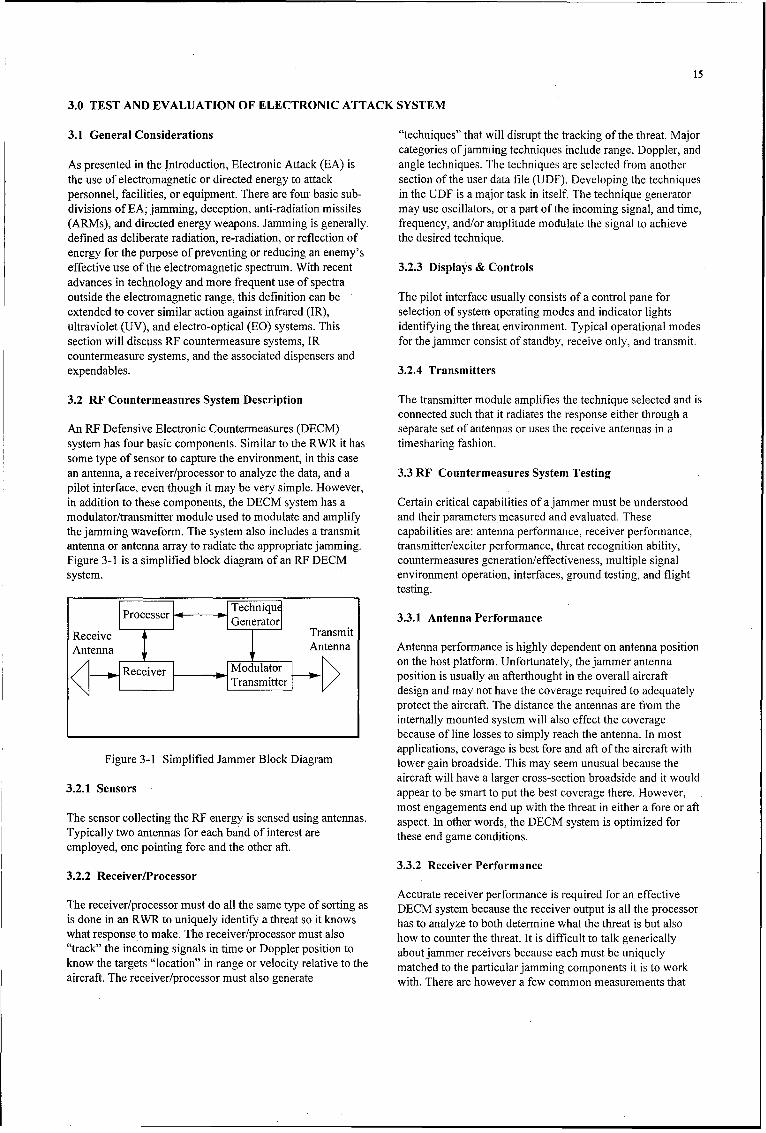
15
3.0 TEST AND EVALUATION OF ELECTRONIC ATTACK SYSTEM
3.1 General Considerations "techniques" that will disrupt the tracking of the threat. Majorcategories of jamming techniques include range, Doppler, and
As presented in the Introduction, Electronic Attack (EA) is angle techniques. The techniques are selected from anotherthe use of electromagnetic or directed energy to attack section of the user data file (UDF). Developing the techniquespersonnel, facilities, or equipment. There are four basic sub- in the UDF is a major task in itself. The technique generatordivisions of EA; jamming, deception, anti-radiation missiles may use oscillators, or a part of the incoming signal, and time,(ARMs), and directed energy weapons. Jamming is generally- frequency, and/or amplitude modulate the signal to achievedefined as deliberate radiation, re-radiation, or reflection of the desired technique.energy for the purpose of preventing or reducing an enemy'seffective use of the electromagnetic spectrum. With recent 3.2.3 Displays & Controlsadvances in technology and more frequent use of spectraoutside the electromagnetic range, this definition can be The pilot interface usually consists of a control pane forextended to cover similar action against infrared (IR), selection of system operating modes and indicator lightsultraviolet (UV), and electro-optical (EG) systems. This identifying the threat environment. Typical operational modessection will discuss RF countermeasure systems, IR for the jammer consist of standby, receive only, and transmit.countermeasure systems, and the associated dispensers andexpendables. 3.2.4 Transmitters
3.2 RF Countermeasures System Description The transmitter module amplifies the technique selected and isconnected such that it radiates the response either through a
An RF Defensive Electronic Countermeasures (DECM) separate set of antennas or uses the receive antennas in asystem has four basic components. Similar to the RWR it has timesharing fashion.some type of sensor to capture the environment, in this casean antenna, a receiver/processor to analyze the data, and a 3.3 RF Countermeasures System Testingpilot interface, even though it may be very simple. However,in addition to these components, the DECM system has a Certain critical capabilities of a jammer must be understoodmodulator/transmitter module used to modulate and amplify and their parameters 'measured and evaluated. Thesethe jamming waveform. The system also includes a transmit capabilities are: antenna performance, receiver performance,antenna or antenna array to radiate the appropriate jamming. transmitter/exciter performance, threat recognition ability,Figure 3-1 is a simplified block diagram of an RF DECM countermeasures generation/effectiveness, multiple signalsystem. environment operation, interfaces, ground testing, and flight
___________________________________________ testing.
Processer Gecnerato 3.3.1 Antenna Performance
Receive TasiAn~na: Antenna Antenna performance is highly dependent on antenna position
AModulator on the host platform. Unfortunately, the jammer antennaS Receiver position is usually an afterthought in the overall aircraftNTransmitter design and may not have the coverage required to adequately
protect the aircraft. The distance the antennas are from theinternally mounted system will also effect the coveragebecause of line losses to simply reach the antenna. In mostapplications, coverage is best fore and aft of the aircraft with
Figure 3-1 Simplified Jammer Block Diagram lower gain broadside. This may seem unusual because theaircraft will have a larger cross-section broadside and it would
3.2. Senorsappear to be smart to put the best coverage there. However,most engagements end up with the threat in either a fore or aft
The sensor collecting the RE energy is sensed using antennas, aspect. In other words, the DECM system is optimized forTypically two antennas for each band of interest are these end game conditions.employed, one pointing fore and the other aft.
3.2. ReciverProcssor3.3.2 Receiver Performance
Accurate receiver performance is required for an effectiveThe receiver/processor must do all the same type of sorting as DECM system because the receiver output is all the processoris done in an RWR to uniquely identify a threat so it knows has to analyze to both determine what the threat is but alsowhat response to make. The receiver/processor must also how to counter the threat. It is difficult to talk generically"track" the incoming signals in time or Doppler position to about jammer receivers because each must be uniquelyknow the targets "location" in range or velocity relative to the matched to the particular jamming components it is to workaircraft. The receiver/processor must also generate with. There are however a few common measurements that

16
need to be performed on the receiver. Receiver sensitivity is a 3.3.4 Threat Recognition Abilitykey measurement because it gives a good idea about how welllow power signals are received. This will hopefully allow the A countermeasures system needs to be able to identify thejammer to correctly identify the threat before the system is threat before it can respond with a technique that has beenwithin firing range, and therefore be prepared to counter it optimized for that threat. Therefore, a major requirement for awhen it does come into range. In general, more sensitivity is countermeasures system is that it be able to uniquelybetter. However, to achieve higher sensitivity one must look recognize as many radars as possible. This capability is aover a smaller bandpass and therefore it may take longer to function of the receiver as well as the processing features ofsearch the entire RE range of interest. How accurate a receiver the countermeasures system.measures the frequency of a threat is important in a jammerbecause the jammer may use this measurement to tune a 3.3.5 Countermeasures Generation/Effectivenesstransmitter to that frequency to generate RE energy that willbe received by the threat radar. The measurement must be Countermeasures generation is one of many functionsaccurate to within several megahertz to be in the bandpass of performed in the processor. Over the last 50 years as radarsthe threat radars receiver. Several other general desirable have evolved, ways to defeat radars called countermeasuresreceiver characteristics can be found in Section 2.3.2 on "techniques" have also evolved. A countermneasures techniqueRWRs. makes the victim radar think the aircraft is somewhere other
then where it actually is. This is accomplished by modifying a3.3.3 Transmitter/Exciter Performance target return in time, amplitude, or frequency. The jammer
may also generate enough power (noise) to simply "hide"The effective radiated power (ERP) of the DECM system is behind.very important because in most cases the more power beingradiated the better the effectiveness of the technique. ERP is Technique effectiveness must be evaluated with respect to thethe power of the transmitter minus the power lost through specific radars to be defeated. These evaluations vary intransmission lines to the antenna plus the gain of the antenna. sophistication based on the data available about the threatSo ERP of the ECM system installed on the aircraft is radar. Parametric ranges of the technique generator can befrequency dependent and angle dependent and directly defined after the total range is determined based on whichproportional to the power of the transmitter. Another radars the system is to be capable ofjamming. To performcalculation that is helpful in evaluating the effectiveness of a effectiveness evaluations, a thorough understanding of thejamming technique is the JIS ratio. The "J" is the power of the threat radar is required. Ideally, this would encompass firstjammer at the input to the receiver of the threat radar, and the having complete documentation of the victim radar to analyze"S" is the power of the radar reflected off the aircraft at the the signal processing and tracking algorithms. Next, analysisreceiver of the radar. It is beyond the scope of this document on a computer model of the radar is accomplished. Thento thoroughly explain J/S ratio; however, a basic knowledge is laboratory testing is conducted to gain a broad understandingrequired. The JIS ratio is almost always measured in dBs. A of the technique ranges that are effective against the radar.positive JIS means that the jammer signal is larger than the Finally, flight tests against the actual radar are conducted.skin signal. A jammer with a much smaller ERP than a radar However, rarely do all these opportunities exist. Either all thecan still achieve positive JIS ratios mainly because power test assets do not exist or there is not enough time or money todecreases as a function of R squared where R is the range utilize them.between the aircraft and the radar. The jammer only has aone-way loss ( 1R2) whereas the radar has a two-way loss How effective a jammer is against a specific radar can be(11R4). The smaller the cross-section of the aircraft the less measured several ways. The easiest measurement ofenergy that can be reflected off of it. This decreases the effectiveness to understand is "miss distance." An effectivestrength of the radar return. In fact, RCS reduction can be technique may cause the missile guidance radar to misguideconsidered another type of countermeasure and needs to be the weapon to the target. The degree of error in missileincluded in overall platform countermeasures capabilities, guidance caused by the EW technique is characterized as missTypes of antenna polarization and the actual frequencies distance. If it is possible to test against an actual system, youbeing used also affect the J/S ratio. may actually be able to fire a missile. More likely though,
even if an actual radar is available, it is too expensive to fire aThe transmitter is supposed to only amplify and output the missile; so tracking error data will be collected from the radarspecific signal injected into it. However, the output of the and input into a computer model of the missile to obtaintransmitter needs to be monitored to see that it does not missile miss distance estimates.produce "extra" or spurious signals. Spurious signals are mostlikely to occur at harmonics of the injected signal but they These steps would allow you to optimize the techniquemay appear anywhere in the spectrum due to errors in system against a particular radar. It must also be understood that thedesign, manufacture, or installation. These spurious signals optimum technique may not be the best solution to actuallycan be used by the threat's counter-countermeasures and waste program in the jammer because the jammer must have enoughvaluable jammer power intended to defeat the threat, resources available to respond to multiple signals. Sometimes
a less than optimum technique is utilized so the system maywork better in a multiple threat environment.
17
3.3.6 Multiple Threat Environment Operation density, dynamic test scenarios.
The jammer's ability to operate in a multiple threat 3.3.9 Flight Testingenvironment is the most difficult capability to evaluatebecause many things are occurring at one time. The ECM Flight testing is the final step in the testing process. The ECMsystem's operation in a multiple threat environment is system is installed in an operational configuration and flownhowever the best indication of how well the system is against actual radars. These radars may be actual threat radarsoperating. The multiple threat environment is what the system or high fidelity simulations. The tester must thoroughlywill see in combat, and the test scenarios need to be understand the capabilities of the radar systems employed.developed to match as closely as possible the environment Planning flightpaths and maneuvers to take full advantage ofthat the system is expected to see in combat. the test assets is a critical part of Open-Air Range (OAR)
flight tests. Instrumentation and the availability of data3.3.7 Interface/Integration Testing products may have a bearing on which flight profiles and test
conditions are utilized. Initial flights may consist of only oneThe ECM system may be designed to interface with other threat system being turned on at a time to get a baselineonboard avionics. A likely interface is some kind of capability and correlate in-flight operation with ground testcommunication with the RWVR to possibly help resolve observations. Effectiveness data can be collected and shouldambiguities. A blanking scheme may also be in place. be compared against laboratory results. More and more threatsBlanking is where either the ECM system tells the RWR to are turned on as confidence is gained that the system isnot look at a certain time because it is transmitting and the performing as it should. A wingman scenario may be requiredRWVR will receive bad data or the RWR signals the jammer to determine if there is any interaction with the on-boardnot to transmit because it is looking for threat signals in the avionics between the two aircraft. In particular, an evaluationenvironment. This -interface needs to be well thought out of the jammer's threat identification capabilities in thebecause the possibility exists for the RAWR to tell the jammer presence of other friendly aircraft can be critical.not to transmit right when it is in the process of defeating anincoming missile. Modern interfaces include a communication 3.4 IR Countermeasureswith the aircraft computer to present either RWVR or ECMdata to the pilot on a multifunction display. Conventional infrared (IR) jammers are electrically powered
countermeasures (CM) sets designed to provide aircraft with3.3.8 Ground Testing protection against heat-seeking missiles. They are the electro-
optical (EO) analogue of RF jammers. These incoherent IRThere are many different ground tests during the development jammers are "turn-on and forget" pieces of equipment whichof a DECM system and many are identical to the tests provide continuous CM protection in flight.performed on an RWR as detailed in Section 2.3. Actualantenna performance needs to be characterized at a The IR jammer provides CM protection against threatsmeasurement facility. HITL testing will expose the ECM depending upon the particular seeker JR spectrum bandpasssystem to realistic threat signals and a dense threat and electronic technique of processing the incoming target IRenvironment. Parametric testing of the receiver and radiation. These IRjammers are generally characterized astransmitter are usually conducted at the contractor facility but having 1) a wide IR spectrum (I to 5 micrometers) in whichspot checks should be done in the HITL to assure system is pulsed JR radiation is emitted, and 2) a wide field of viewstill performing to specification. In the HITL, threat detection, (180 to 360 degrees azimuth coverage is nominal). The CMidentification, technique generation, and multiple signal techniques for some of thege EW systems can be changedenvironment capabilities are determined. The testing begins while in flight to provide different protection levels toby stimulating the ECM system with a single open-loop threat different threat classes.emitter to determine the one-on-one system identificationoperation. Techniques generated can be monitored on a A common technique to enhance the lR jammer CMspectrum analyzer. Technique effectiveness can be tested with performance is to reduce the IR signature of the targetclosed-loop simulators; first one-on-one and then in a multiple aircraft. This can be accomplished by a variety of means:signal environment. After the HITL tests are completed the installing engine exhaust suppressers or by using low IRsystem moves on to an ISTF where the ECM system is first signature paint on the aircraft fuselage. To further enhancetested in the actual platform in which it will be used. IRCM performance, flare expendables are often used with JRElectromagnetic interference tests are performed at this time. jammers.An ISTF is the best place to perform avionics interface testingfor the entire platform databus structure. Interface testing Generally, a complete IRjammer system consists of one orinvolves exercising every link that will be operational during several transmitters, a modulated power supply, and pilotflight. Again, the rule is to start slow. Test only two systems control indicator. The system radiates a modulated JR signalat a time and then, when basic interfaces are found to be designed to disturb the detection and/or tracking functions ofperforming correctly, add more systems on line. EMI and an incoming JR guided missile and cause it to miss theEMC testing is also performed at the ISTF. Installed antenna intended target aircraft. A complete IR CM system can weighpatterns can be investigated in the ISTF environment. Some as little as 40 pounds to more than 200 pounds. The inputEW-oriented ISTFs can produce closed loop, high signal power requirement can vary anywhere from 1000 watts to

18
over 3000 watts. However, there is a tradeoff in increasing JR Specifically, the higher the amount of modulated radiationjammer radiated output power with increased jammer volume output (provided by the jammer) over the host aircraftand input power consumption. This limitation effectively signature, the better the IR countermeasures performance willrestricts the IR jammers in production to the simpler Bands be in countering the threat of the same IR spectrum bandpass.I/IJ/IV threat classes as opposed to the more complex IR Depending upon type of jammer and threat seekers, theseekers such as JR imaging seekers, minimum JIS ratios for 'acceptable JR countermeasures
protection' vary from about 2 to 10 dB depending uponA unique feature of these systems is that there is no sensor. jammer type and particular threat.The systems are operating using a priori data. They do notprovide any threat missile warning to the pilot or to other 3.5.1 Ground Testselectronic devices on board the host aircraft.
In a laboratory environment, the jammer signature can be3.4.1 Processors measured with great precision with a radiometer. In the field,
the host aircraft signature can be measured and used toThe "processor" of an JR countermeasures system is a calculate the J/S if the measurement range, angle (azimuthmodulated power supply that is used to drive the transmitter. and elevation), and meteorological conditions (barometricThrough threat analysis or exploitation, the scanning pressure, ambient temperature, and relative humidity) arefrequencies of the missile tracking circuits are determined and known along the measurement range. Careful instrumentationthese frequencies are programmed into circuitry used to calibration is essential for repeatability of JR measurementmodulate the power supply. The modulated power supply is data points.either present as stand alone hardware in the cargo bay area orintegrated in the transmitter. In both cases, manual switches Air-to-ground testing is another way of obtainingare present to allow selection of preprogrammed jam codes. simultaneous measurements of both jammer and signature inAdditional CM codes can be preprogrammed as new threats the field. Normally, if the target aircraft is a helicopter with anare defined. IRjammer on board, several 360 degree azimuth passes at
several different altitudes would be conducted for a fixed3.4.2 Controls and Displays ground-located J/S radiometer. This test would generate J/S
ratio signatures for several elevation look angles and for theThe pilot interface is through a control indicator located in the JR bands of interest.cockpit. The pilot control indicator is either a stand-alonemodule for the IR jammer or it is shared with an another EW 3.5.2 Flight Testingsystem. The interface is usually quite simple, only providing ameans of turning the system on or off and a way to alert the This 'realistic condition' testing is much more expensive andpilot that a malfunction has occurred, harder to accomplish than air-to-ground testing since it would
involve two aircraft [target aircraft plus chase/measurement3.4.3 Transmitter aircraft]. The resultant JR data can be used in the JFS ratio
analyses if the J data parameters are known with certainty forThere are several methods to generate the required JR the test conditions which the S-only data were collected.countermeasures pulses. One technology uses heated carbon-material rods and mechanical modulation techniques to 3.6 Dispensers and Expendablesgenerate the pulsed JR radiation to confuse the incomingmissile seeker. Another technology uses an arc lamp in a Dispensers usually consist of a number of modules whichvacuum tube, which is electronically modulated to provide the when integrated become an operational dispensing system.required pulsed JRCM radiation. Typical components include a cockpit control unit, a
programmer, sequencers, the actual dispenser and magazine,The JR transmitters usually have a wide field of view (180 to and a safety switch. Expendables are the items that are360 degrees in azimuth). The usual placement of the JR literally fired out of the magazine and are designed to presenttransmitter is as close to the engine exhaust as possible since a target-like signature to the attacking missile. Dispensers aremost of the JR threat missile seekers tend to initially acquire somewhat unique in that they usually rely on another systemand lock onto this 'hot spot.' as the sensor that triggers the operation of the dispenser.
Either a missile warning system, a radar warning system, or3.5 IR Countermeasures System Testing an aircrew member will initiate the command to start
dispensing expendables. Figure 3-2 shows a simplified blockA major figure of merit for JRjammer effectiveness is the diagram of a dispenser system.jammer-to-signal ratio that the system can achieve.

19
Inputs from Control frequency are typical RF threat parameters.
MWS and Response Data: Response data involve the specificRWR Programmer dispensing technique against a known or identified threat.
Responses consist of IR expendables, RF expendables (chaff),or a combination. Dispense techniques are defined by the
Sequenser quantity and intervals at which the expendables are deployed.
Payload Data: Payload data identify' the types of
DipnsrDispene expendables loaded into the dispenser and are available to bedispensed. During flight, the system monitors the magazine tokeep track of how many expendables and of what type have
~j~i Magzinbeen used.
3.6.3 Sequencer
The sequencer distributes power and commands to theFigure 3-2 Simplified Dispenser Block Diagram dispensers. The sequencers perform payload inventories and
determine if a misfire has occurred. Typically, one sequencer3.6.1 Control is used for every two dispensers.
The Cockpit Control Unit provides the operator interface. It 3.6.4 Dispensermay be a separate module providing mode and status controlor be provided by interfacing with other EW systems. The dispensers are housings for the magazines and areDispenser mode and status may be shown on the RWR installed in the aircraft at the location where the expendablesdisplay. Another option is that the dispenser is interfaced are to be released.through the aircraft's mission computer to be displayed to theoperator via another cockpit display. The magazines are the modules that actually hold the
expendables. Before the individual expendables are inserted3.6.2 Programmer into the magazines, the "squibs," the firing mechanisms, are
inserted into the magazine; one squib for each expendable.The programmer receives the inputs from either the MWS or Squibs can only be used once and must be replaced like thethe RWR and automatically decides what dispense technique expendab les. Expendables are then loaded into the magazinesto use. On most systems, the pilot may also be able to in a safe area and then an entire magazine is inserted into amanually program data to dispense a particular number and dispenser housing before each flight. Typical magazines ontype of expendables for a known threat. When a missile tactical aircraft hold approximately 30 expendables.warning indication is received, the pilot can then press aswitch to dispense a predetermined number and type of The safety switch is specifically mentioned here to highlightexpendables if he or she does not wish to use the automatic the need to be careful around the pyrotechnic devices thatprogram. In some cases, the dispensing system will be make up part of the expendables package. The switch, whenoperating on a data bus where it can receive aircraft attitude engaged, does not allow any current to reach the dispenser,and navigation data to further help in determining what thus eliminating the chance of an accidental squib firing.dispensing program to use. Also, the dispenser may send datato the aircraft's mission computer providing status of the 3.6.5 Expendablesdispenser system.
Expendables exist to defeat both IR and RF threat systems.The programmer is the dispensers' processor and is where The most common examples are flares that go against IRboth the Operational Flight Program (OFP) and the MDF are missiles and chaff to go against RF systems, both radar andlocated. Typically, dispensers developed today are designed to missile. There are numerous configurations for both chaff andoperate with threat optimization dispensing. This means the flares. Conventional flares are made of various combinationsOFP and the MDF will tailor the dispensing programs for the of magnesium, phosphorus, and teflon which is ignited whenenvironment in which the platform is operating. The OFP the flare is dispensed from the magazine and tries to "look"contains algorithms that calculate and dispense the like the aircraft engine radiation. More sophisticated flaresexpendables as a result of aircraft attitude data and threat data. using new materials are currently being developed that willThe OFP works in conjunction with the MDF data to more closely represent the signature of the aircraft.determine appropriate threat responses. Specific data typicallyincluded in the MDF are: Chaff is made of metal coated glass fibers or aluminum foil
strips. When dispensed it separates in the air stream and triesThreat Data: Threat data consist of the parametric to present a larger cross-section than the aircraft and capture
data that define the threat system. Pulse width, RE frequency the tracking functions of the threat radar. The radar or missilerange, amplitude or scan modulation, and pulse repetition will then track the chaff and not the aircraft. RE "decoys" that
20
are actually small repeater jammers are the latest entry into "bloom" rate, which is how fast the expendable can achievethe realm of expendables. These devices can be dispensed in the desired RCS, fall rate, and actual frequency range overflight and towed behind the host aircraft to create a missile to which the RCS can be achieved.track the decoy and miss the aircraft.
3.7.1 Ground Testing3.7 Dispenser and Expendable Testing
In laboratory tests, system components are cycled through allSystem hardware testing includes verifying that each separate switch settings. Dispenser outputs are monitored with testmodule is functional and operates within system design equipment to verify output performance as a function of inputparameters. Power tests, continuity tests, voltage tests, and parameters. Initial interface testing is also conducted withbuilt in tests (BITs) are performed. These tests help to isolate other avionics/EW systems to verify correct interfaceany hardware configuration or interface problems. System operation between systems.software tests are performed on the module that contains thesystem software programs. These tests help to isolate any Laboratory tests provide simulated threat parameters to beprogramming errors or timing errors, and verify that the injected into operational integrated dispenser suites to verifysystem software has been correctly programmed and all that the EW Suite will perform as specified in a near-realsoftware functions are performned. Thorough software testing environment. Operational dispen ser programs are monitoredis critical to assure that complex functions are properly and verified against known threat input to ensure threatexecuted and that latent coding errors are not introduced, detection, identification, and countermeasure techniques areSuch errors can not only impact system performance, but may correct. Dispense techniques may require that severaleffect safety and survivability. Both manual and automatic expendables be launched in a specific pattern to be effectivedispense "programs" that have been loaded into the MDF are against certain threats. Timing sequences are measured forconfirmed. accuracy.
System integration tests are conducted to ensure that all During installed system test facility testing, dispenser systemssystem modules will function as designed when connected are installed in an aircraft and all functional tests are repeatedtogether as a complete system. All modules are continuously to verify the system operates properly in an operationaltested to verify the dispenser system will operate with other environment. These tests are conducted to verify electrical,avionics systems installed in aircraft. These tests help to mechanical, software, and EMC/EMI issues have beenisolate system integration problems. resolved.
Suite integration testing involves connecting the avionics 3.7.3 Flight Testingsystems and EW systems that the new dispenser system willbe working with, and monitoring the operation. The dispenser Unlike jammers, RWRs, and Electronic Support Systems,system is usually connected via a Mil-Std-1 553 or similar data dispensers, and their associated expendables can only be fullybus. Also, an actual aircraft computer is connected, or the evaluated in flight. Their overall effectiveness is dependent oncomputer is simulated, to help identify any software interface not only the characteristics of the countermeasure but also onproblems. These tests will uncover compatibility problems the aerodynamic effects at the time of launch. In addition tobetween systems and also any bus problems that may occur. characterizing the effectiveness of these countermeasures,Suite integration problems may be very subtle and difficult to testing must be accomplished to ensure that the performanceisolate due to the number of hardware and software systems and utility of the aircraft are not adversely effected. Flightinvolved. tests are conducted with EW dispenser systems installed in or
on the aircraft for which they are intended. Flight tests areExpendables are tested according to design specifications and performed to verify all systems are integrated and performingrequirements. Parametric data recorded for IR expendables to design specifications. Aircraft are flown against real andinclude time to ignite, total burn time, spectral emission, and simulated threats at an appropriate OAR.intensity. RE expendables are tested to measure RCS,
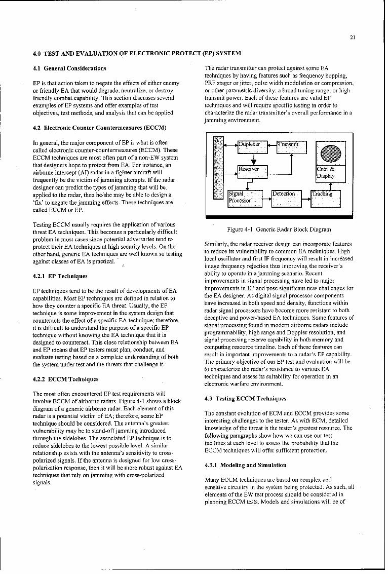
21
4.0 TEST AND EVALUATION OF ELECTRONIC PROTECT (EP) SYSTEM
4.1 General Considerations The radar transmitter can protect against some EAtechniques by having features such as frequency hopping,
EP is that action taken to negate the effects of either enemy PRF stager or jitter, pulse width modulation or compression,or friendly EA that would degrade, neutralize, or destroy or other parametric diversity; a broad tuning range; or highfriendly combat capability. This section discusses several transmit power. Each of these features are valid EPexamples of EP systems and offer examples of test techniques and will require specific testing in order toobjectives, test methods, and analysis that can be applied, characterize the radar transmitter's overall performance in a
jamming environment.4.2 Electronic Counter Countermeasures (ECCM)
In general, the major component of EP is what is often n Duplexer Transmitcalled electronic counter-countermeasures (ECCM). TheseECCM techniques are most often part of a non-EW system 0that designers hope to protect from EA. For instance, an n Rcie nrairborne intercept (Al) radar in a fighter aircraft will n Receiveryfrequently be the victim of jamming attempts. If the radaradesigner can predict the types of jamming that will be.applied to the radar, then he/she may be able to design a Signal Decto Tracking'fix' to negate the jamming effects. These techniques are Processor
called ECCM or EP.
Testing BCCM usually requires the application of variousthreat BA techniques. This becomes a particularly difficult Figure 4-1 Generic Radar Block Diagram
problem in most cases since potential adversaries tend toprotect their BA techniques at high security levels. On the Similarly, the radar receiver design can incorporate features
other hand, generic BA techniques are well known so testing to reduce its vulnerability to common BA techniques. High
against classes of BA is practical. local oscillator and first IF frequency will result in increasedimage frequency rejection thus improving the receiver's
4.2. EP echnquesability to operate in a jamming scenario. Recentimprovements in signal processing have led to major
EP techniques tend to be the result of developments of BA improvements in BP and pose significant new challenges for
capabilities. Most EP techniques are defined in relation to the EA designer. As digital signal processor components
how they counter a specific EA threat. Usually, the EP have increased in both speed and density, functions within
technique is some improvement in the system design that radar signal processors have become more resistant to both
counteracts the effect of a specific BA technique; therefore, deceptive and power-based BA technique s. Some features of
it is difficult to understand the purpose of a specific EP signal processing found in modern airborne radars include
technique without knowing the BA technique that it is programmability, high range and Doppler resolution, and
designed to counteract. This close relationship between BA signal processing reserve capability in both memory and
and BP means that BP testers must plan, conduct, and computing resource timeline. Bach of these features can
evaluate testing based on a complete understanding of both result in important improvements to a radar's EP capability.
the system under test and the threats that challenge it. The primary objective of our EP test and evaluation will beto characterize the radar's resistance to various EA
4.2.2 ECCM Techniques techniques and assess its suitability for operation in anelectronic warfare environment.
The most often encountered BP test requirements willinvolve BCCM of airborne radars. Figure 4-1 shows a block 4.3 Testing ECCM Techniques
diagram of a generic airborne radar. Bach element of thisradar is a potential victim of BA; therefore, some BP The constant evolution of BCM and BCCM provides some
technique should be considered. The antenna's greatest interesting challenges to the tester. As with BCM, detailed
vulnerability may be to stand-off jamming introduced knowledge of the threat is the tester's greatest resource. The
through the sidelobes. The associated BP technique is to following paragraphs show how we can use our test
reduce sidelobes to the lowest possible level. A similar facilities at each level to assess the probability that the
relationship exists with the antenna's sensitivity to cross- BCCM techniques will offer sufficient protection.
polarized signals. If the antenna is designed for low cross-4.1MoeigadSmltnpolarization response, then it will be more robust against BA431MoeigadSmltntechniques that rely on jamming with cross-polarized Many BCCM techniques are based on complex andsignals. sensitive circuitry in the system being protected. As such, all
elements of the BW test process should be considered inplanning BCCM tests. Models and simulations will be of
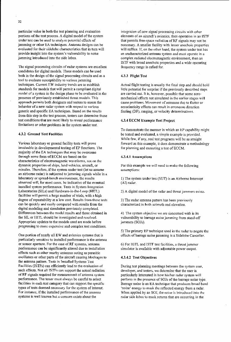
22
particular value in both the test planning and evaluation integration of new signal processing circuits with otherportions of the test process. A digital model of the system elements of an aircraft's avionics, then operation in an ISIFunder test can be used to analyze potentfial effects of that permits free-space radiation of RF signals may not bejamming or other EA techniques. Antenna designs can be necessary. A smaller facility with lesser anechoic propertiesevaluated for their sidelobe characteristics that in turn will will suffice. If, on the other hand, the system under test hasprovide insight into the system's vulnerability to noise an uncharacterized antenna system and must operate in ajamming introduced into the side lobes, complex radiated electromagnetic environment, then an
ISTF with broad anechoic properties and a wide operatingThe signal processing circuits of radar systems are excellent frequency range is called for.candidates for digital models. These models can be usedboth in the design of the signal processing circuits and as a 4.3.3 Flight Testtool to evaluate susceptibility to various jammingtechniques. Current EW industry trends are to establish Actual flight testing is usually the final step and should holdstandards for models that will permit a compliant digital little potential for surprise if the previously described stepsmodel of a system in the design phase to be evaluated in the are carried out. It is, however, possible that some aero-presence of previously established threat models. This mechanical effects not simulated in the earlier stages willapproach permits both designers and testers to assess the cause problems. Movement of antennas due to flutter orbehavior of a new radar system with respect to various aeroelasticity effects can result in erroneous directiongeneric and specific EA techniques. Based on the results finding (DF), ranging, or velocity determinations.from this step in the test process, testers can determine thosetest conditions that are most likely to reveal performance 4.3.4 ECCM Example Test Projectlimitations or other problems in the system under test.
To demonstrate the manner in which an EP capability might4.3.2 Ground Test Facilities be tested and evaluated, a simple example is provided.
While few, if any, real test programs will be as straightVarious laboratory or ground facility tests will prove forward as this example, it does demonstrate a methodologyinvaluable in developmental testing of EP functions. The for planning and executing a test of ECCM.majority of the EA techniques that may be overcomethrough some formn of ECCM are based on the 4.3.4.1 Assumptionscharacteristics of electromagnetic waveforms, not on thedynamic properties of ships, land vehicles, aircraft, or For this example we will need to make the followingmissiles. Therefore, if the system under test (let us assume assumptions:an airborne radar) is subjected to jamming signals while in alaboratory or spread-bench environment, the results 1) The system under test (SUT) is an Airborne Interceptobserved will, for most cases, be indicative of the eventual (AI) radar.installed system performnance. Tests in System IntegrationLaboratories (SILs) and Hardware-in-the-Loop (HITL) 2) A digital model of the radar and threat jammers exists.facilities will permit a large number of trials, with a highdegree of repeatability at a low cost. Results from these tests 3) The radar antenna pattern has been previouslycan be quickly and easily compared with results from the characterized in both azimuth and elevation.digital modeling and simulation previously completed.Differences between the model results and those obtained in 4) The system objective we are concerned with is itsthe SIL or HITL should be investigated and resolved, vulnerability to barrage noise jamming from stand-offAppropriate updates to the models used are made before jammers (SOJs).progressing to more expensive and complex test conditions.
5) The primary EP technique used in the radar to negate theOne portion of nearly all EW and avionics systems that is effects of barrage noise jamming is a Sidelobe Canceller.particularly sensitive to installed performance is the antennaor sensor aperture. For the case of RF systems,'antenna 6) For HITL and ISTF test facilities, a threatjammerperformance can be significantly altered due to installation simulator is available with adjustable power output.effects such as other nearby antennas acting as parasiticoscillators or other parts of the aircraft causing blockages to 4.3.4.2 Test Objectivesthe antenna pattern. Tests in Installed Systems TestFacilities (ISTFs) can efficiently lead to the evaluation of During test planning meetings between the system user,such effects. Not all ISTFs can support the actual radiation developer, and testers, we determine that the user isof RI' signals required for measuremenit of antenna system particularly interested in how his/her radar system willperformance. The tester must always be careful to select perform in the presence of SOJs of the barrage noise type.facilities in each test category that can support the specific Barrage noise is an EA technique that produces broad bandtypes of tests deemed necessary for the system of interest. 'noise' energy to mask the reflected energy from a radar.For instance, if the installed performance of the antenna When applied by an SOJ, the noise is introduced into thesystems is well known but a concern exists about the radar side lobes to mask returns that are occurring in the
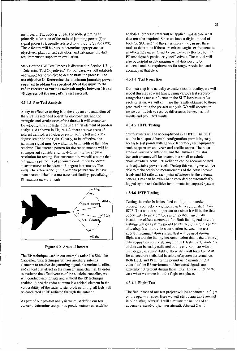
23
main beam. The success of barrage noise jamming is analytical processes that will be applied, and decide whatprimarily a function of the ratio of jamming power (J) to data must be acquired. Since we have a digital model ofsignal power (S), usually referred to as the J to S ratio (J/S). both the SUT and the threat (jammer), we can use theseThese factors will help us to determine appropriate test tools to determine if there are critical angles or frequenciesobjectives, plan our test activities, and determine the data at which the jamming will be particularly effective (or therequirements to support an evaluation. EP technique is particularly ineffective!). The model will
also be helpful in determining what data need to beStep I of the EW Test Process is discussed in Section 1.7. 1, collected and the requirements for range, resolution, and"Determine Test Objectives." For our case, we will establish accuracy of that data.one simple test objective to demonstrate the process. Thetest objective is: Determine the minimum jamming power 4.3.4.4 Test Executionrequired to obtain the specified JIS at the input to theradar receiver at various azimuth angles between 10 and Our next step is to actually execute a test. In reality, we will45 degrees off the nose of the test aircraft, repeat this step several times, using various test resource
categories as our confidence in the SUT increases. After4.3.4.3 Pre-Test Analysis each iteration, we will compare the results obtained to those
predicted during the pre-test analysis. We will correct orA key to effective testing is to develop an understanding of revise our models to resolve differences between actualthe SUT, its intended operating environment, and the results and predicted results.strengths and weaknesses of the threats it will encounter.Developing this understanding is the first element of pre-test 4.3.4.5 HITL Testinganalysis. As shown in Figure 4-2, there are two areas ofinterest defined; a 35-degree sector on the left and a 35- Our first tests will be accomplished in a HITL. The SUTdegree sector on the right. Clearly, to be effective, the will be in a 'spread bench' configuration permitting easyjamming signal must be within the bandwidth of the radar access to test points with generic laboratory test equipmentreceiver. The antenna pattern for the radar antenna will be such as spectrum analyzers and oscilloscopes. The radaran important consideration in determining the angular antenna, auxiliary antennas, and the jammer simulatorresolution for testing. For our example, we will assume that transmit antenna will be located in a small anechoicthe antenna pattern is of adequate consistency to permit chamber where actual RF radiation can be accommodatedmeasurements to be taken at 5-degree increments. The with adjustable power levels. During this testing we will beinitial characterization of the antenna pattern would have able to make precision measurements of the actual powerbeen accomplished in a measurement facility specializing in levels and J/S ratio at each point of interest in the antennaRF antenna measurements. pattern. Data can be either hand recorded or automatically
logged by the test facilities instrumentation support system.
-45 deg4.3.4.6 ISTF Testing
-10 deg Testing the radar in its installed configuration under
Z Area of interest precisely controlled conditions can be accomplished in anISTE. This will be an important test since it will be the first
+10 deg opportunity to measure the system performance withArea of interet installation effects accounted for. Both facility and aircraft
instrumentation systems should be utilized during this phaseof testing. It will provide a correlation between the testaircraft instrumentation system that will be used during
+45 deg flight test and the facility instrumentation that is the primarydata acquisition source during the ISTE tests. Large amounts
Figure 4-2 Areas of Interest of data can be easily collected in this environment with ahigh degree of repeatability. These data will form the basis
The EP technique used in our example radar is a Sidelobe for an accurate statistical baseline of system performance.Canceller. This technique utilizes auxiliary antenna Both HITL and ISTF testing permit us to maintain tightelements to receive the jamming signal, determnine its effect, control of the RF environment. Unwanted signals areand cancel that effect in the main antenna channel. In order generally not present during these tests. This will not be theto evaluate the effectiveness of the sidelobe canceller, we case when we move in to the flight test phase.will conduct testing with and without the EP techniqueenabled. Since the radar antenna is a critical element in the 4.3.4.7 Flight Testvulnerability of the radar to stand-off jamming, all tests willbe conducted at RF radiated through the antenna. The final phase of our test project will be conducted in flight
on the open-air range. Here we will plan using three aircraftAs part of our pre-test analysis we must define our test in our testing. Aircraft 1 will simulate the actions of anconcept, determine test points, predict outcomes, establish adversarial stand-offjammer aircraft. Aircraft 2 will
24
represent a threat target aircraft. Our test aircraft, number 3, generally be communicated through an interim or finalwill carry the SUT and be instrumented to provide either report. This report should clearly state any constraints oronboard recording or telemetry of critical parameters limitations on the testing, what was observed, what wasneeded for evaluation of the SUT. We will also require concluded from those observations, and anyTime Space Positioning Information (TSPI) for all three recommendations resulting from those conclusions. If,aircraft. These data will be used during post test analysis to based on the evaluation, the decision makers can verify thatdetermine the exact position of the jammer and target with any operational risks associated with fielding the system arerespect to our radar antenna. acceptable, and that user needs are adequately satisfied, then
testing can be declared complete. If the evaluation leads to aWe will establish flight profiles for all three aircraft to conclusion that the SUT requires additional improvementmaintain the jammer aircraft within the 35-degree sector on prior to acceptance or fielding, then another cycle of the testeither the left or right side of the test aircraft. During this process will occur.phase of testing we can modify our test objective to providea more operational flavor. The objective is now redefined 4.4 Electronic Protect Through Emissions Controlas: Determine the minimum jamming power required to Capabilitiesdefeat the radar's ability to detect, track, and display a1 square meter target with standoff jamming at various In addition to the ECCM techniques discussed above, otherazimuth angles between 10 and 45 degrees off the nose of passive approaches to EP are used in most modern militarythe test aircraft. systems. The most direct means of limiting an adversary's
ability to apply EA techniques is by rigid control of friendlyThis revised objective creates a number of new electromagnetic emissions (EMCON). As a simple examplerequirements. First, the objective is couched in terms of a of this process, consider an Anti-Radiation Missile (ARM)target aircraft with a radar cross section (RCS) of 1 square targeted at a friendly radar site. Since the ARM guides onmeter. While the aircraft available to serve as a target may the RF radiation from the radar, it will loose that guidance ifnot directly meet this requirement, data obtained during the radar transmissions are ceased. The planned cessation oftesting can be corrected for the difference in RCS. This does the radar emissions would be considered a form of EMCONhowever require high accuracy and resolution TSPI and would clearly be an effective method of EP.capability on the open-air range. Second, the primaryindicator of jamming effectiveness will now be the pilot of Many systems may rely on detecting, identifying, andthe test aircraft. V/hen the jamming is sufficient to obscure tracking targets on the basis of unintended emissions orthe target on the pilot's display, then we will consider that radiation. The EP technique used to negate this effect isthe EP technique is ineffective. While the precise data electromagnetic shielding or hardening.gathered during the previous phases of testing are necessaryto efficiently develop and improve the SUT, these 4.5 Testing for Unintentional Emissions and EMCONoperational data will, in the final analysis, determine Capabilitieswhether or not the system will be acquired and fielded.
Virtually all electrical and electronic components on an4.3.4.8 Evaluation aircraft have the potential to radiate or re-radiate RF energy
which may be detected and intercepted by an adversary.So what do the results of each of the tests mean to the While some of these potential emissions can be observeddeveloper or the user? Each may have a different view of during early phases of development, it is most often the casewhat the results mean; the developer may use the results of that they are discovered after all systems are installed, andtesting to demonstrate that all specifications have been integration in the host platform has begun. As a result,satisfied, while the user may determine that based on test Installed System Test Facilities (ISTFs) are frequentlyresults, the system will not satisfy his/her needs. Due to the brought into play to characterize these unintendeddifferences in interpretation of test results and the potential emissions.economic and operational impacts associated with theseinterpretations, evaluation is the most critical and 4.5.1 Ground Testscontroversial element of the test process. It is important that,to the greatest extent possible, all parties involved in the Large anechoic chambers are most useful in conductingdevelopment and test of a system reach agreement prior to tests to determine the exact nature and source of all signalsthe start of testing as to what data will be used in the radiated from an aircraft during operation. One approachevaluation, and what calculations and statistics will be frequently used is to establish a matrix of all possible switchapplied to the data. Finally, everyone must reach agreement combinations and then step through each configurationas to exactly what constitutes success or failure. while using a calibrated, high sensitivity receiver to sweep
through the entire range of frequencies to be evaluated. IfFor our example test we bounded the problem to some energy is detected with a particular combination of aircraftdegree in the statement of our test objectives. For the flight equipment energized, then engineers can isolate the exacttest objective, only data acquired when the jamming aircraft source. At this point both the user and designer mustis within the 10 to 45-degree sector on either side of the test determine what action is to be taken to either reduce theaircraft will be used. The evaluation of the test results will emission or accept the condition.
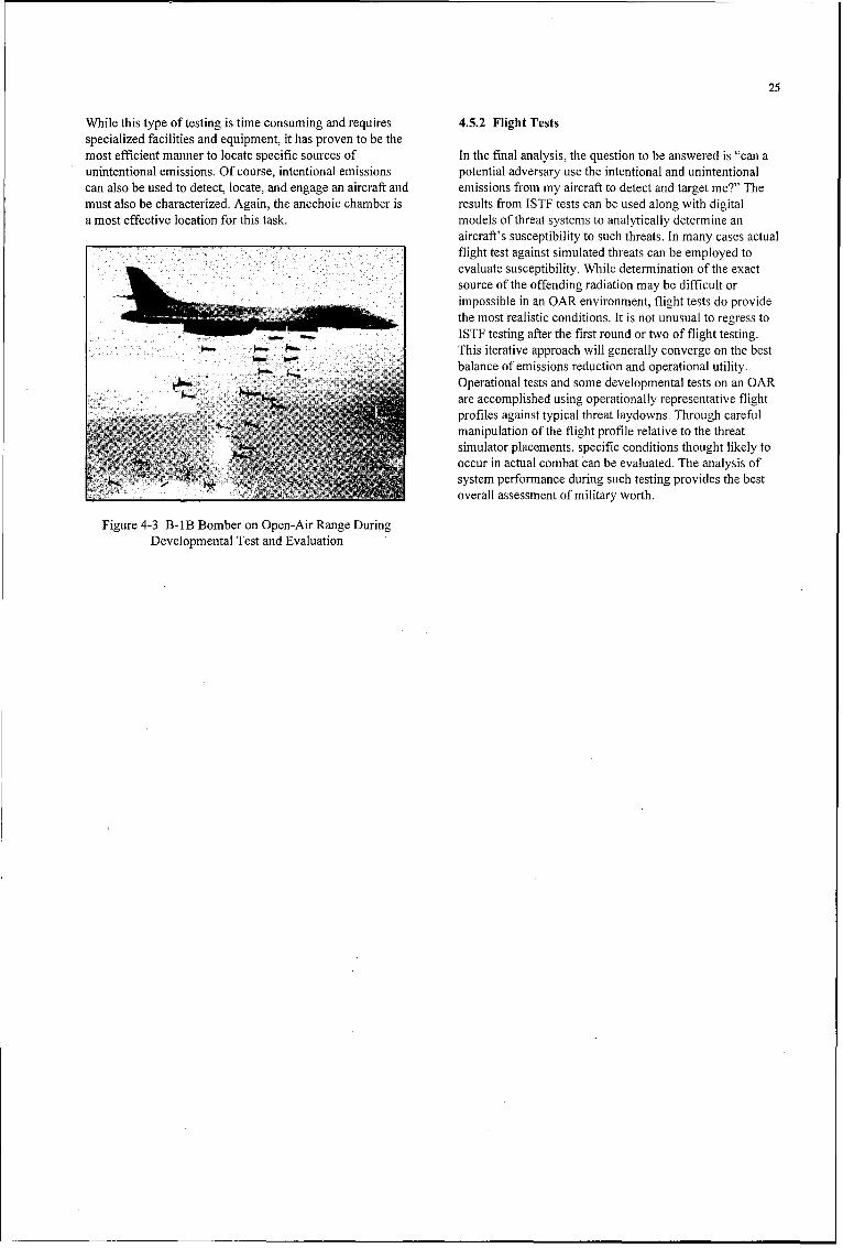
25
While this type of testing is time consuming and requires 4.5.2 Flight Testsspecialized facilities and equipment, it has proven to be themost efficient manner to locate specific sources of In the final analysis, the question to be answered is "can aunintentional emissions. Of course, intentional emissions potential adversary use the intentional and unintentionalcan also be used to detect, locate, and engage an aircraft and emissions from my aircraft to detect and target me?" Themust also be characterized. Again, the anechoic chamber is results from ISTF tests can be used along with digitala most effective location for this task. models of threat systems to analytically determine an
aircraft's susceptibility to such threats. In many cases actualflight test against simulated threats can be employed toevaluate susceptibility. While determination of the exactsource of the offending radiation may be difficult orimpossible in an OAR environment, flight tests do providethe most realistic conditions. It is not unusual to regress toISTF testing after the first round or two of flight testing.This iterative approach will generally converge on the bestbalance of emissions reduction and operational utility.Operational tests and some developmental tests on an OARare accomplished using operationally representative flightprofiles against typical threat laydowns. Through carefulmanipulation of the flight profile relative to the threatsimulator placements, specific conditions thought likely tooccur in actual combat can be evaluated. The analysis of
E system performance during such testing provides the bestoverall assessment of military worth.
Figure 4-3 B- 1 B Bomber on Open-Air Range DuringDevelopmental Test and Evaluation

26

27
5.0 EW SYSTEM ARCHITECTURE
5.1 Architectural Considerations 5.3 Federated EW Systems
The approach to testing any specific EW system or function From the tester's point of view, federated systems representwill be dependent to some extent on the architecture it is the next step in complexity. Additional interfaces will becontained within. The examples in the preceding sections are, considered in the design of the test program. A depiction offor the most part, based on stand-alone EW and avionics this architecture is shown in Figure 5-1.systems. Testing and the subsequent evaluation of stand-alonesystems are relatively straight forward. When the EW system 5.3.1 Federated System Descriptionis combined with other systems and sub-systems on a singleplatform, both the quantity and nature of interactions which Federated systems are those systems which maintain theirmust be considered grow substantially. In this section, we will own functional identities or boundaries, but are dependent onfocus on testing federations of systems and integrated data, information, cueing, or other functions from othersystems. systems outside of those boundaries. Most avionics and EW
systems of the 1970's through the early 1990's have exhibited5.2 Stand-Alone EW Systems this characteristic. Testing of such systems becomes
considerably more complex than the stand-alone caseThe simplest category of EW systems from a T&E point of " previously discussed. The causes of this complexity are bestview are those which act independently of other systems understood by reviewing an example test process for acarried on the same platform. These "stand-alone" systems federated RWR and RF jamming system.can usually be evaluated without a rigorous evaluation of theperformance of other aircraft functions. Of course,interoperability and Electromagnetic Interference (EMI)issues must be considered for stand-alone systems.
5.2.1 Stand-Alone System Description
Stand-alone EW systems are those systems that do not dependon data, information, cueing, or other functions from otherEW or avionics systems on the platform. Most EW systemsdeveloped during the 1950's and 1960's fit into this category.These systems generally have a specific and singular functionsuch as radar warning, jamming, or chaff dispensing. Testingof such systems is relatively simple; the system is exposed tothe expected threat environment and observed for the correctresponse.
5.2.2 Stand-Alone System Test Example Figure 5-1 Federated System in HITL Test at ECSEL
Facility, Pt. Mugu, California
As an example, we will look at the case of a stand-alone radarwarning receiver (RWR) designed to provide the pilot with a 5.3.2 Federated System Test Examplevisual and audio warning in the event that his/her aircraft isilluminated by any of several threat radar systems. As For this example we will assume that the RWR and jammerdiscussed in Section 2 of this document, specific tests will be will be installed on the same platform and that they will bothperformed in both ground and flight environments to measure be designed to work against the same set of threats. They willthe performance of each major functional element of the share a common threat database or User Data File (UDF).RWR. The antennas will be characterized individually and in When a threat is detected by the RWR it will be displayed ontheir installed configuration to verify their frequency and the multifunction display in the cockpit. The display willspatial coverage and gain performance. Receiver tests will be show a unique symbol representing the threat type, azimuth,conducted to determine sensitivity, selectivity, and other key and estimated lethality. The pilot will also receive a warningparameters. The signal processing function will be tested to tone in his headset. Upon command from the pilot, the threatensure that all threat signals specified for the system are identification and location data will be passed to the jammerproperly categorized. Finally, the man-machine interfaces sub-system. The jammer will determine the optimum(MMIs) will be evaluated for correct operation. While this jamming response for the detected threat, tune a receiver tooverall process may require hundreds of individual tests, the the proper frequency, and emit the necessary RF energy. If theevaluation of results remains simplistic and the test conditions jamming is effective, the RWR will detect that the radar is nocan be easily obtained. Each element of the system either longer tracking the aircraft. From this scenario we can beginfunctions as desired, or not; each test condition is discrete and to structure our example test program, determine the testhas little or no dependence on other test conditions. resource requirements, and plan an evaluation process.

28
As with any test, planning is the key to success. Our test 5.4 Integrated EW Systemsplanning must start with defining test objectives. For eachobjective we must then determine the criteria for evaluation Some recent combat aircraft designs have moved from the(that is, we must establish what is satisfactory performance), a relatively simple federated approach to an extensivecriteria for success of the test (how much testing is enough), integration of EW/avionics functions. The U.S. Air Forceand the analysis process that will be applied to test data. For F-22 is an example of this integrated approach. Functionalthe example system described above we might develop test integration offers numerous advantages to system designersobjectives such as: while creating new challenges to testers.
0 Determine the time for the RWR to detect each threat 5.4.1 Integrated System Descriptionsignal in the UDF.
Integrated EW systems are not just a combination of stand-0 Determine the mean time to initiate the optimum alone systems linked together as is the case with the federated
jamming waveform. approach. Rather, integrated systems tend to have ahomogeneous functional identity. There is no discernible
While many other objectives could be established for this boundary between sub-functions such as radar warning,relatively simple system, these will suffice to demonstrate the missile warning, jamming, or other EW activities. Most, if nottest approach. The first objective appears to be focused on the all, components in the system may be shared between the sub-stand-alone performance of the RWR. However, on closer functions on the basis of complex scheduling and resourceinspection, we can see that there is potential for interaction control algorithms.with the jammer through the UDF. If both the jammer and theRWR are attempting to access the UDF simultaneously, there 5.4.2 Testing Integrated EW Systemsmay be a delay in the data needed by the RWR. As a result,testing must be structured to acquire data under various Testing of isolated functionality becomes difficult, if notoperating conditions for both the RWR and the jammer. Data impossible, with the operational software in place. Flight testscollected must be categorized to reflect the operating will reveal little of the source of performance problems withconditions to determine if there is a significant delay imposed integrated systems. HITL and ISTF test facilities that canby multiple systems sharing a common UDF. This then brings make large numbers of test runs with precisely controlledus to the next challenge; a definition of how much delay is conditions and extensive instrumentation are essential to theacceptable. And we must know what is acceptable before we test and evaluation of integrated systems.begin testing in order to establish the range, resolution, andaccuracy of our test observations. If a delay greater than 100 The OAR remains useful in establishing the overallmilliseconds is unacceptable and our instrumentation system effectiveness of integrated EW systems (Figure 5-2).only has a resolution of one second, then we may not be able However, in order to evaluate the system effectiveness into distinguish between acceptable and unacceptable conditions outside that which can be demonstrated with OARperformance. Certainly the stand-alone performance of the resources, the tester must rely on digital modeling andRWR will be a dominant factor in this objective, but simulation and ground-based resources. The current trend isadditional testing to ascertain the overall performance of the to combine digital models with hardware threat andfederated system is of paramount importance to the user. environment simulations to provide controllable, repeatable
stimulation of the entire test aircraft in an ISTF.Our second objective clearly implies evaluation of the fullyfederated system; the RWR, jammer, shared UDF, multi-function display, and the pilot will all play an important rolein overall effectiveness. However, to fully evaluate andunderstand the results of this test we must also have insight ofthe performance of each individual component of the system.We will want to know not only if improvements are required,but if so, which part of the system is the best candidate forimprovement. This objective also brings into play the humanoperator; a component with a high degree of variability. Inorder to appreciate the operator's effect on overall systemperformance, we will have to collect data under a wide rangeof operational conditions, and with a range of operators. All
of this leads to the conclusion that test of federated systemsbrings about an increased burden on the test planning andanalysis processes over that of the stand-alone systems test.The same facilities will be used, but the number of test runs orflights may increase significantly as the system complexitygrows. Figure 5-2 US Navy F/A-18 Conducting Flight Test of
Integrated EW System at Electronic Combat Range, ChinaLake, California

29
This capability to immerse the entire aircraft in a controlled must reflect realistic target motion and the resulting changesand representative EW environment requires that all signals of in the physical characteristics of each signal. Radar targetinterest (RF, IR, UV) be simultaneously generated in a returns must be modulated with the correct Doppler,coherent manner. Information content must be consistent scintillation, and other characteristics to permit a viable test ofamong and between emissions from both the system under a coherent processing airborne intercept radar. If, due totest (SUT) and the simulated environment. All objects used in minor time or space positioning errors in the simulation, thethe test scenario must appear to exist at the right time and JR emissions from the target were displaced from the radarplace; that is, coherency must exist in all domains detectable target simulation, then the SUT may declare two targets ratherby the SUT. than one. Clearly, the eventual outcome of a 1 versus 1
engagement should be different than a 1 versus 2 engagement.These requirements drive ISTF signal and scene generation This difference would invalidate the planned test. For ISTFand scenario control software to the far extreme of our current testing of modern integrated EW systems, this simple exampletechnical capability. A simple example serves to help must be replicated many times to represent realistic threatunderstand this demand on the test facility. Let us assume the densities. Very sophisticated and costly threat and signalintegrated EW system being tested can sense both RF and JR generation systems, scenario control software, digital models,emissions from a potential threat aircraft and correlate this and instrumentation are needed to accomplish these highsensor data with its own radar detections and tracks. The test density, high fidelity simulations. However, in spite of thefacility will then be required to generate a radar return (of the cost and complexity involved, such test capability can paycorrect RCS), an JR scene, and other RE emissions all coming great dividends in understanding the behavior of integratedfrom the intended target position. As we look at this EW systems and isolating hardware and software failures.requirement in the time domain, we see that all simulations

30

31
6.0 MODELING AND SIMULATION FOR EW TEST AND EVALUATION
6.1 General Considerations for Modeling and Simulation multi-platform composite forces opposing numerous threats(M&S) (many on many). Mission level models frequently include the
impact of the enemy's command and control capability on theThe application of models and simulations throughout the EW outcome.test process has been long recognized as a critical adjunct toboth ground and flight test. In many cases, models of 6.1.3 Campaignunverified fidelity have been used, only to lead to speculationor even confusion. In this section a rigorous, yet pragmatic Campaign level is similar to mission level except that aapproach to use of M&S in test and evaluation (T&E) is campaign is a many-on-many simulation including thesuggested. impacts of having to sustain the mission for an extended
period of time. It evaluates effectiveness and force6.1.1 Introduction survivability of friendly, multi-platform composite forces
opposing numerous threats, but also includes the issuesUse of M&S is a critical part of the EW Test Process. It can associated with human factors, logistics, and attrition.be argued that all testing is in fact a simulation of war. Thischapter focuses on the application of digital M&S to the EW 6.1.4 TheaterTest Process. Digital M&S is the representation of "reality"through the use of models and computers. Digital M&S can This level incorporates the C41 contributions ofjoint-Serviceno longer be considered solely a tool for determining EW (i.e., Army-Air Force-Navy) and allied forces operationssystem requirements from campaign and mission against a combined threat force (force on force). It integratesrequirements-it is the thread that binds and shapes the EW the various missions into regional, day and night, and jointTest Process. This section describes how digital M&S may operations, and assesses the input of electronic warfare onprovide unique and practical benefits to the EW tester. Digital force effectiveness.models and computer simulations are used to representsystems, host platforms, other friendly players, the combat 6.1.5 Objectivesenvironment, and threat systems. They can be used to helpdesign and define EW systems and testing with threat The objectives of M&S in the test process are to:simulations and missile flyout models. Due to the relativelylow cost of exercising these models, this type of activity can . Define safety footprints or limits.be run many times to check what ifs and explore the widest Exrplttetdainou-sab ruavlbepossible range of system parameters without concern for rgmsflight safety. These models may run interactively in real or rgmssimulated time and space domains, along with other factors of 0 Increase sample size once confidence in the model isa combat environment, to support the entire T&E process. established.
6.1.2 Levels of Complexity 0 Define test facility requirements (e.g., number and typesof threats, airspace required, control of background noise
Computer simulations are constructed to the following levels and emitters, and instrumentation).
of technical complexity. * Define and optimize test scenarios.
6.1.2.1 Engineering 0 Select test points (i.e., successful results would notindicate the need for additional heart-of-the-enve lope
Component level model used to examine technical testing).
performance of an individual component or sub-system in * Predict test results for each test objective.accordance with its intended design.
6.1.6 Purpose6.1.2.2 Engagement
The EW T&E Process uses M&S and analysis prior to testingWeapon system level models used to evaluate effectiveness, to help design tests and predict test results, and after testing toincluding associated tactics and doctrine, in the context of an extrapolate test results to other conditions. At each stage ofintegrated weapon system engaged with a single (one-on-one) the test process, models in the simulation are replaced withor a few (one on few) enemy threats (i.e., Surface-to-Air hardware to achieve increasing fidelity to support evaluation.Missile system) in a simulated scenario. In this way M&S is part of all six resource categories. M&S
should also be used to provide constant feedback for system6.1.2.3 Mission development/improvement.
Multiple weapon systems level models (with varying degreesof detail) combined into a simulated mission to analyzemission effectiveness and force survivability of friendly,
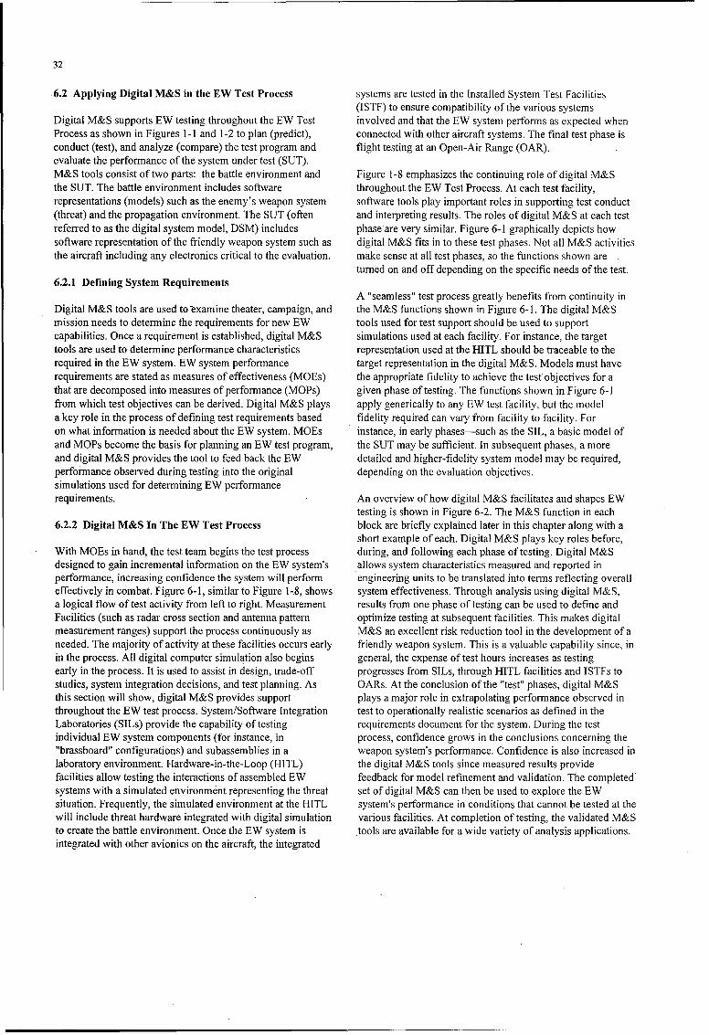
32
.6.2 Applying Digital M&S in the EW Test Process systems are tested in the Installed System Test Facilities(ISTF) to ensure compatibility of the various systems
Digital M&S supports EW testing throughout the EW Test involved and that the EW system performs as expected whenProcess as shown in Figures 1-1 and 1-2 to plan (predict), connected with other aircraft systems. The final test phase isconduct (test), and analyze (compare) the test program and flight testing at an Open-Air Range (OAR).evaluate the performance of the system under test (SUT).M&S tools consist of two parts: the battle environment and Figure 1-8 emphasizes the continuing role of digital M&Sthe SUT. The battle environment includes software throughout the EW Test Process. At each test facility,representations (models) such as the enemy's weapon system software tools play important roles in supporting test conduct(threat) and the propagation environment. The SUT (often and interpreting results. The roles of digital M&S at each testreferred to as the digital system model, DSM) includes phaseare very similar. Figure 6-1 graphically depicts howsoftware representation of the friendly weapon system such as digital M&S fits in to these test phases. Not all M&S activitiesthe aircraft including any electronics critical to the evaluation, make sense at all test phases, so the functions shown are
turned on and off depending on the specific needs of the test.6.2.1 Defining System Requirements
A "seamless" test process greatly benefits from continuity inDigital M&S tools are used to examine theater, campaign, and the M&S functions shown in Figure 6-1. The digital M&Smission needs to determine the requirements for new EW tools used for test support should be used to supportcapabilities. Once a requirement is established, digital M&S simulations used at each facility. For instance, the targettools are used to determine performance characteristics representation used at the HITL should be traceable to therequired in the EW system. EW system performance target representation in the digital M&S. Models must haverequirements are stated as measures of effectiveness (MOEs) the appropriate fidelity to achieve the test objectives for athat are decomposed into measures of performance (MOPs) given phase of testing. The functions shown in Figure 6-1from which test objectives can be derived. Digital M&S plays apply generically to any EW test facility, but the modela key role in the process of defining test requirements based fidelity required can vary from facility to facility. Foron what information is needed about the EW system. MOEs instance, in early phases-such as the SIL, a basic model ofand MOPs become the basis for planning an EW test program, the SUT may be sufficient. In subsequent phases, a moreand digital M&S provides the tool to feed back the EW detailed and higher-fidelity system model may be required,performance observed during testing into the original depending on the evaluation objectives.simulations used for determining EW performancerequirements. An overview of how digital M&S facilitates and shapes EW
testing is shown in Figure 6-2. The M&S function in each6.2.2 Digital M&S In The EW Test Process block are briefly explained later in this chapter along with a
short example of each. Digital M&S plays key roles before,With MOEs in hand, the test team begins the test process during, and following each phase of testing. Digital M&Sdesigned to gain incremental information on the EW system's allows system characteristics measured and reported inperformance, increasing confidence the system will perform engineering units to be translated into terms reflecting overalleffectively in combat. Figure 6-1, similar to Figure 1-8, shows system effectiveness. Through analysis using digital M&S,a logical flow of test activity from left to right. Measurement results from one phase of testing can be used to define andFacilities (such as radar cross section and antenna pattern optimize testing at subsequent facilities. This makes digitalmeasurement ranges) support the process continuously as M&S an excellent risk reduction tool in the development of aneeded. The majority of activity at these facilities occurs early friendly weapon system. This is a valuable capability since, inin the process. All digital computer simulation also begins general, the expense of test hours increases as testingearly in the process. It is used to assist in design, trade-off progresses from SILs, through HITL facilities and ISTFs tostudies, system integration decisions, and test planning. As OARs. At the conclusion of the "test" phases, digital M&Sthis section will show, digital M&S provides support plays a major role in extrapolating performance observed inthroughout the EW test process. System/Software Integration test to operationally realistic scenarios as defined in theLaboratories (SILs) provide the capability of testing requirements document for the system. During the testindividual EW system components (for instance, in process, confidence grows in the conclusions concerning the"brassboard" configurations) and subassemblies in a weapon system's performance. Confidence is also increased inlaboratory environment. Hardware-in-the-Loop (HITL) the digital M&S tools since measured results providefacilities allow testing the interactions of assembled EW feedback for model refinement and validation. The completed'systems with a simulated environment representing the threat set of digital M&S can then be used to explore the EWsituation. Frequently, the simulated environment at the HITL system's performance in conditions that cannot be tested at thewill include threat hardware integrated with digital simulation various facilities. At completion of testing, the validated M&Sto create the battle environment. Once the EW system is tools are available for a wide variety of analysis applications.integrated with other avionics on the aircraft, the integrated
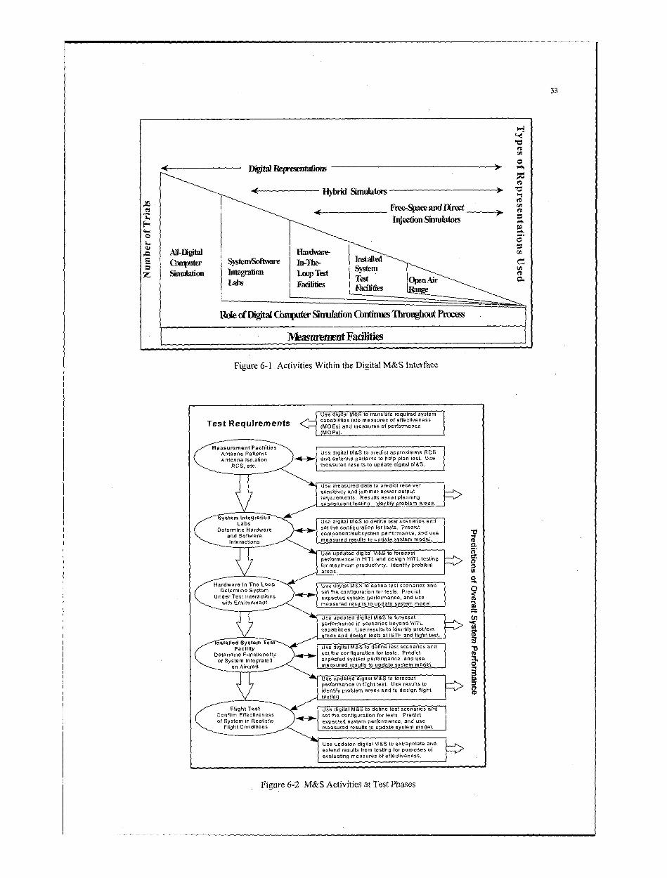
33
to
- 4 ~ ~~~Dogtal Representations~brdSmltr
Hybrido Simulators
z Simulation Ineon SmiufatoTes
Labs-igta Faciiie et pnir-
Lal~~ Facililcis T estOe -
1FA* of Digtal COnputer Sinuaton Continues Thiouhul Process
Mmasimmmt Faciliies
Figure 6-1 Activities Within the Digital M&S Interface
Test Requirements capablitie, s into measures.1of effecýtivedessI
( MOEs) and measures of performance(Mo ps).
And e sofatwaoe srcmponent/suboysternstoerformpanctest adUseRCec measured results to update digitel moda.
Use mpdatued daitalto preto torecaste
performacemints Resut% atddsign pltantesingtots maium prdciiydniy problem aes
and Sofware eopoet/subsystern performance, and use
Intteractironmsn measured results to update system model.
Use updated digitat M&S to torct IIpe!rformance in sceL naro deysig HITteting.
apeabiiis. Us eutt dniy psilrnareasar Ind desi Loo te t0t1 T n ti ttt s
Deterine SstemUse digital M&S to dative test scenarios andd
Udeermines Funtctionaltr settise configuration for tests, Predictot Sytem ntegatesexpected system performance, and use
measured results to update system meodel, a
performanle iflgtea.Use results toidetif prsoslem areats andtoeinfih
FacilityUseupae digital M&S to dfntextscnrapolat anid
anAirraft extuend results troi udtentn tsre prposes0 of
evaluating ~ U mesreutite tvnssto
Figure 6-2 t& Act ivities a&to Tiejst Phscenaisan
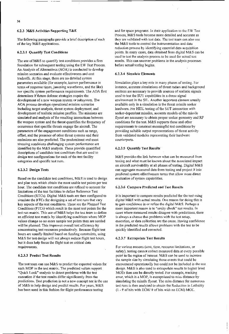
34
6.2.3 M&S Activities Supporting T&E and for space programs. In their application to the EW TestProcess, M&S tools become more detailed and accurate as
The following paragraphs provide a brief description of each they are validated with test data. The test team can also useof the key M&S applications, the M&S tools to control the instrumentation and data
reduction process by identifying essential data acquisition6.2.3.1 Quantify Test Conditions points. In many cases, data obtained from digital M&S can be
used to test the analysis process to be used for actual testThe use of M&S to quantify test conditions provides a firm results. This can uncover problems in the analysis processesfoundation for subsequent testing using the EW Test Process. before actual testing begins.An Analysis of Alternatives (AOA) is conducted to developmission scenarios and evaluate effectiveness and cost 6.2.3.4 Simulate Elementstradeoffs. At this stage, there are no detailed systemparameters available (for example, known performance in Simulation plays a key role in many phases of testing. Forterms of response times, jamming waveforms, and the like) instance, accurate simulations of threat radars and backgroundnor specific system performance requirements. The AOA first emitters are necessary to provide sources of realistic signalsdetermines if future defense strategies require the used to test the SUT capabilities in a dense signaldevelopment of a new weapon system or subsystem. The environment in the SIL. Another important element usuallyAOA process develops operational mission scenarios available only in a simulation is the threat missile seekerincluding target analysis, threat system deployment, and hardware. For HITL testing of the SUT interaction withdevelopment of realistic mission profiles. The missions are seeker-dependent missiles, accurate models of the missilesimulated and analysis of the resulting interactions between flyout are necessary to obtain proper seeker geometry and RFthe weapon system and the threat quantifies the frequency of conditions for the test. M&S supports these and otheroccurrence that specific threats engage the aircraft. The requirements to construct meaningful test conditions byparameters of the engagement conditions such.as range, providing suitable output representations of threat activityoffset, and the presence of other threat systems and their from validated modules representing their hardwareemissions are also predicted. The predominant and most counterparts.stressing conditions challenging system performance areidentified by the M&S analysis. These provide quantified 6.2.3.5 Quantify Test Resultsdescriptions of candidate test conditions that are used todesign test configurations for each of the test facility M&S provides the link between what can be measured fromcategories and specific test runs. testing and what must be known about the associated impact
on aircraft survivability at all phases of testing. Digital M&S6.2.3.2 Design Tests can aggregate measured data from testing and project it into
predicted system effectiveness terms that allow more directBased on the candidate test conditions, M&S is used to design evaluation of system capabilities.and plan tests which obtain the most usable test points per testhour. The candidate test conditions are refined to account for 6.2.3.6 Compare Predicted and Test Resultslimitations of the test facilities to define Reference TestConditions (RTCs). Digital M&S tools are then configured to It is important to compare results predicted for the test usingsimulate the RTCs for designing a set of test runs that vary digital M&S with actual results. One reason for doing this iskey aspects of the test conditions. These are the Planned Test to gain confidence in or refine the digital M&S. Perhaps aConditions (PTCs) which result in the most test points for the more important reason is to "sanity check' test results. Intest run matrix. This use of M&S helps the test team to define cases where measured results disagree with predictions, therean efficient test matrix by identifying conditions where MOP is always a chance that problems with the test setup,values change so no more sample test points than are needed execution, or data collection are the cause. Having confidencewill be planned. This improves overall test efficiency by in the predicted results allows problems with the test to beconcentrating test resources productively. Because flight test quickly identified and corrected.hours are usually limited based on funding constraints, usingM&S for test design will not always reduce flight test hours, 6.2.3.7 Extrapolate Test Resultsbut it does help focus the flight test on critical datarequirements. For various reasons (cost, time, resource limitations, or
safety), testing cannot collect measured data at every possible6.2.3.3 Predict Test Results point in the region of interest. M&S can be used to increase
the sample size by simulating those events that could beThe test team can use M&S to predict the expected values for encountered operationally but could not be included in the testeach MOP in the test matrix. The predicted values support design. M&S is also used to extrapolate results to higher level"Quick Look" analysis to detect problems with the test MO~s than can be directly tested. For example, trackingexecution if the test results differ significantly from the error, which is a MOP, is extrapolated to miss distance bypredictions. Test prediction is not a new concept nor is the use simulating the missile flyout. The miss distance for numerousof M&S to help design and predict results. For years, M&S test runs is then analyzed to obtain the Reduction in Lethalityhas been used in this fashion for flight performance testing (I - # of hits with ECM/ # of hits with no ECM) MOE.

35
Validation of the M&S models and extrapolation of results Predict Test Results: The DSM, threat, environment, andprovide the test team with tools to connect the MOPs to aircraft models will be used to predict the range between thesystem effectiveness, which make test results meaningful to aircraft and threat at which the system under test (SUT)program management in reaching decisions concerning the initially detects each threat along the test scenario.program.
Extrapolate Test Results: Validated DSM models will be used6.2.4 Examples of Applying Digital M&S During Test to extend the measured results to include assessment ofPhases detection range performance against emitters not available in
the SIL. This allows follow-on analysis to incorporate newlyThis section describes how a test team can use digital M&S at assessed threat capabilities or deployments without revisitingeach test phase. This is not a comprehensive description of the SIL facility.M&S throughout the EW T&E Process-just a sampling ofhow M&S can be used. One example MOP is selected for 6.2.4.3 Hardware In The Loop Example: Track Erroreach phase of the process to illustrate contributions of M&S at MOPeach test phase. As testing progresses through the process, thetest team collects more measured data. As a result, there will Output jamming waveforms must cause sufficient degradationbe a reduction in remaining MOEs/MOPs to be predicted in threat tracking of the aircraft or effects of missilethrough simulation. As a specific example of this process, the engagements will be unacceptable.measured installed antenna patterns obtained at themeasurement facility will replace the engineering estimated Design Tests: Threat models capable of predicting threatantenna patterns in the DSM. The MOEs/MOPs will be radar responses to electronic countermeasures (called "ECcomputed or re-computed using the updated model(s). capable" models) are used to evaluate the capability of the
self-protection system to achieve a given degradation in threat6.2.4.1 Measurement Facility Example: Antenna Pattern tracking performance at various target offsets and altitudes.Measurement for Field-of-View MOP Assessment Resulta.:nt effectiveness estimates will be used to design the
HIlL test setup and to specify offsets and altitudes.The system's antennas must provide visibility throughout the PrdcTetRsl: Sheandnvomnaloesrequired range of azimuth and elevation. If the achieved field- Preict Teusedto Resualts: DSM, evleso thret adevronmentalt modelsof-view coverage is inadequate, the system will not provide willr bheatmdl used tor esals xeteds vauest ofte rCcpbesutn.rcwarning for threats located outside the achieved field of view. err hetmdl sdfrti utb Ccpbe
Extrapolate Test Results: DSM and BC capable threat modelsDesign Test: The DSM will be used to specify sampling will be used to extend results measured in the HJTL to includeintervals and resolution required in measurements to ensure assessment of SUT-threat interactions in conditions notthe resulting collected data are sufficient (but not wasteful actually measured at the HITL to show SUT sensitivity to"11overkill") for supporting subsequent modeling which uses changes in environmental and/or threat factors that influencethe measurements as input data. tracking error.
Extrapolate Test Results: The DSM will be stimulated with 6.2.4.4 Installed System Test Facility Example: Pulseanalytically combined measured antenna pattern data to Density MOPobserve predicted SUT performance in response to frequencyand polarization combinations not actually part of the Systems must be capable of collecting and processing allmeasurement plan. incident pulses expected in the aircraft scenario. If achieved
pulse processing capability is inadequate, the system cannot6.2.4.2 System Integration Laboratory Example: effectively perform when conditions of pulse density areDetection Range MOP above the achieved capability.
The system's Radar Warning Receiver (RWvR) must warn the Design Tests: Emitter, threat, and environmental models willaircrew at a range from the threat that allows employment of be used to establish incident signal conditions atsuitable countermeasures. If the achieved detection range is representative pulse densities for an operational scenario.inadequate, warning time will not be adequate to allow These signal conditions will be used to design the test set-upeffective countermeasures. and data collection effort at the ISTF.
Design Tests: Surface-to-Air Missile and Airborne Predict Test Results: The aircraft, DSM, emitter, threat, andInterceptor systems, emitters, and environment models can be environmental models will be used to predict SUTused to generate expected power levels for testing jammer and performance in the presence of the signal conditions derivedRWR threat detection capabilities. The corresponding values above.of power will be used to design the test setup and datacollection efforts. In other words, the test team will use this Simulate Elements: Aircraft motion and motion of otherpower as the starting point and proceed up or down in the moving platforms of interest is simulated using digital M&Sscale as necessary to characterize detection capability, in the ISTF.

36
Extrapolate Test Results: Full simulation including the requirements.aircraft, DSM, emitter, threat, and environmental models will Predict Test Results: Simulations used to design the flightexpand the scope of SUT evaluation by extending it to tsswl ernuigdrvdts odtost rdccombinations of laydown, scan schedules, mission profiles, expected shot rates achievable by the threats under ECM andand other conditions not actually measured at the ISTF. non-ECM conditions.
6.2.4.5 Open-Air Range Example: Reduction in Shots Extrapolate Test Results: Full simulation is used to extendMOP results achieved at the OAR to include threat density and
combinations that are not available at the OAR, and to includeJammers must sufficiently decrease the opportunity for the effects of tactics that were not employed during flightmissile launches with ECM versus without it. If a sufficient testing due to test restrictions.number of shot opportunities cannot be denied, overalljamming effectiveness will be inadequate. 6.3 Conclusion
Design Tests: Aircraft, DSM, and threat models will be used Digital M&S plays a critical role in the process of acquiringto design flight tests that provide shot opportunities covering and testing EW systems. Digital M&S is the thread that bindseach tested threat system's engagement envelope and the the various phases of the EW Test Process into amission envelope of the aircraft. Results of simulation will be comprehensive conclusion about the effectiveness of the EWused to design data collection, select threat rules of system. Digital M&S improves with use in the EW Testengagement (such as cueing and firing interval), and reference Process since test results fold back into the M&S tools totime space position information (TSPI) coverage improve their capabilities and the confidence of their users.
37
7.0 EW GROUND-BASED TEST AND EVALUATION RESOURCES AND FACILITIES
7.1 Introduction to Ground-Based Test Resources compatibility (EMI/EMC) test capabilities. Measurementfacilities provide EW and platform antenna pattern
Sections 7 and 8 provide generic descriptions of ground and descriptions and platform signature data critical for systemflight test resources commonly utilized in test and evaluation design and refinement, computer simulation, and HITLof EW systems and components. Detailed descriptions of testing.selected test facilities in the U.S. and Europe are included inthe annex of this document. While the annex does not fully 7.3 System Integration Laboratories (SILs)describe every resource that a project may wish to utilize, itdoes represent a valuable resource for understanding the range SILs are facilities designed to test the performance andof facilities available to meet the goals of a structured test compatibility of components, subsystems, and systems whenprocess. integrated with other systems or functions. They are used to
evaluate individual hardware and software interactions and, atGround-based test resources are frequently categorized by times, involve the entire weapon system avionics suite. Atheir primary function such as measurement facility (MF), variety of computer simulations and test equipment are usedhardware-in-the-loop (HITL) facility, or installed systems test to generate scenarios and environments to test for functionalfacility (ISTF). However, in many cases these definitions are performance, reliability, and safety. SILs are generallyoverly and inappropriately restrictive. For example, large weapon system specific and are found in both contractor andanechoic chambers are generally classified as ISTFs and yet Government facilities.they frequently provide superior support in the role ofmeasurement facilities. The following paragraphs explain the SILs often employ a variety of real-time/near-real-time digitalrole of each of the commonly encountered facility categories models and computer simulations to generate scenarios andbut are not meant to imply that facilities otherwise defined multi-spectral backgrounds. These models are interfaced withshould not be utilized in a role outside their primary brassboard, prototype, or actual production hardware anddesignation. software of the systems under test. SILs are used from the
beginning of an EW system's development through avionics7.2 Measurement Facilities (MFs) integration and fielding. Moreover, SILs continue to be used
to support the testing of hardware and software modificationsMeasurement facilities establish the character of an EW or updates occurring throughout an EW system's operationalrelated system/subsystem or technology. They provide life.capabilities to explore and evaluate advanced technologiessuch as those involved with various sensors and multi-spectral 7.4 Hardware-in-the-Loop (HITL) Facilitiessignature reduction.
HITL facilities are an important test category because theyfrequently represent the first opportunity to test uninstalledsystem components (breadboard, brassboard, pre-productionprototypes, etc.) in a realistic RF, laser, or IR environment.HITL operating environments can provide simulated terraineffects, high signal/threat density, and realistic interactivescenarios. Some HITLs offer multi-spectral capability andbackground noise. Modem threat representation via closed-
-loop hybrid threat simulators can be employed for ECeffectiveness testing, man-in-the-loop interaction, andIntegrated Air Defense System (IADS) networking. Secure
&(shield/screen room) operations, test condition repeatability,"IN and high capacity data collection and recording are common
attributes of the HITL test venue.
7.4.1 HITL Features
HITL facilities are ground-based test facilities that provide aFigure 7-1 STRADI Radar Static Signature Evaluation controlled and frequently secure environment to test EW
Facility at CELAR Facility in France techniques and hardware against simulations of threatsystems. Primary EW HITL facilities contain simulations of
7.2.1 Measurement Facility Subcategories hostile weapon system hardware or the actual hostile weapon
system hardware. They are used to determine threat systemMeasurement facilities generally fall into the sub-categories susceptibility and to evaluate the performance andof antenna characterization, radar cross section (RCS) effectiveness of EW systems and techniques.measurement, infrared/laser signature measurement, andelectromagnetic interference, and electromagnetic

38
crucial to system checkout prior to open-air testing. Failure to
W evaluate installed EW system performance adequately on theground typically results in significantly increased flight testcost and lengthened schedules.
7.5.1 Categories of ISTFs
A Category I ISTF performs end-to-end systems effectivenesstesting on installed multi-sensor/multi-spectral EW and otheravionics systems under a wide range of realistic threat andoperational conditions. These conditions require theappropriate types and numbers of players. Test events rangefrom concept exploration and developmental tests tooperational effectiveness testing. Specific tests include EWeffectiveness (especially multi-sensor cued countermeasures),
Figure 7-2 Hardware-in-the-Loop (HITL) Facility platform susceptibility, human factors, electronic protectionperformance, weapon systems integration performance,
Some EW HITL facilities contain friendly weapon system electronic support systems performance, and systemshardware. They are used to evaluate and improve the integration testing.performance of friendly weapon systems in the presence ofvarious EW activities. These HITL facilities can also be used A Category II ISTF performs end-to-end systems integrationto test EW systems where the friendly weapon system testing on installed multi-sensor/multi-spectral EW and otherrepresents a potential threat technology. avionics systems under conditions necessary to prove system
performance. Test events are primarily DT&E oriented with7.4.2 Use of HITL Facilities some applications to operational testing. Specific tests
include: human factors, electronic protection, avionicsHITL testing should be conducted as early in the development systems performance, and systems integration testing.process as possible - even if that means using a brassboardconfiguration. Too often preproduction hardware is developed A Category III ISTF performs specialized testing such as:late in a program, making identification and correction of RCS measurements, antenna pattern measurements,problems difficult. EW HITL testing provides repeatable susceptibility to high powered microwave, electromagneticmeasurements and verification of protection techniques and environmental effects (E3), and limited systems installationEW system effectiveness. Results obtained from HITL tests and checkout on aircraft, ground vehicles, and components.should be compared to predicted results from previous M&Sactivities. Differences discovered in this comparison are thenanalyzed and the appropriate models are updated.
7.5 Installed System Test Facilities (ISTFs)
ISTFs provide a ground-based capability to evaluate EWsystems that are installed on or integrated with host platforms.These test facilities may consist of anechoic or shieldedchambers in which free-space radiation measurements aremade during the simultaneous operation of EW systems andhost platform avionics and munitions. Threat signalgenerators stimulate the EW SUT, and its responses areevaluated to provide critical, integrated system performanceinformation. Their primary purpose is to evaluate integratedavionics systems (e.g., radar, infrared, communications,navigation, identification, EW systems or subsystems, and Figure 7-3 B-1 Bomber in Large Anechoic Chamber forintegrated controls and displays) in installed configurations to Installed Systems Testingtest specific functions of complete, full-scale weapon systems.Such testing may determine if any EMI/EMC problems exist. 7.6 Distinguishing Factors of Test FacilitiesTesting may also determine system reactions toelectromagnetic environments of hostile and/or friendly While the primary designation (e.g., HITL, ISTF, etc.) of asystems whose signals cannot be radiated in free space on test facility can be used to describe it at a generic level, theopen-air test ranges for security reasons. Support of flight test engineer must consider a number of other characteristicstesting by providing pre-flight and post-flight checkout to determine the applicability of the facility to a particular testcapabilities is yet another role for HITLs. This ground testing effort. The test plan should define the approximatecan aid in isolating component, subsystem, or system characteristics that must be simulated or measured duringproblems not observable in other ground test facilities but each phase of testing. This is the starting point for selection of
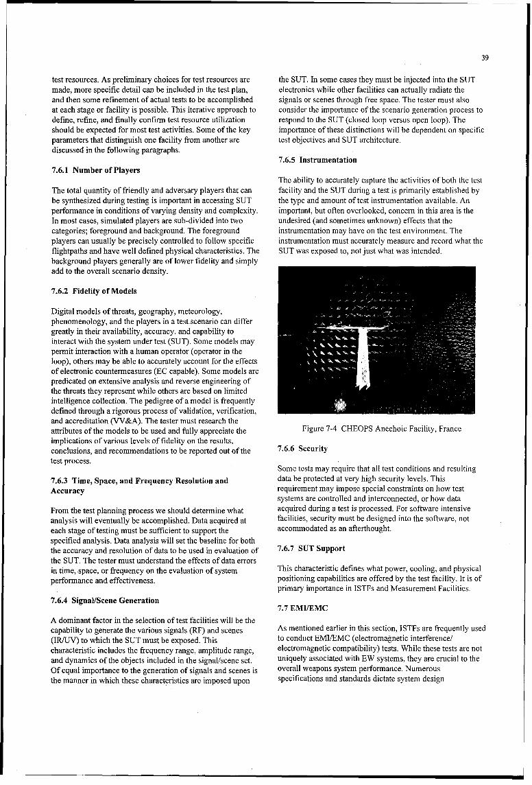
39
test resources. As preliminary choices for test resources are the SUT. In some cases they must be injected into the SUTmade, more specific detail can be included in the test plan, electronics while other facilities can actually radiate theand then some refinement of actual tests to be accomplished signals or scenes through free space. The tester must alsoat each stage or facility is possible. This iterative approach to consider the importance of the scenario generation process todefine, refine, and finally confirm test resource utilization respond to the SUT (closed loop versus open loop). Theshould be expected for most test activities. Some of the key importance of these distinctions will be dependent on specificparameters that distinguish one facility from another are test objectives and SUT architecture.discussed in the following paragraphs.
7.6.5 Instrumentation7.6.1 Number of Players
The ability to accurately capture the activities of both the testThe total quantity of friendly and adversary players that can facility and the SUT during a test is primarily established bybe synthesized during testing is important in accessing SUT the type and amount of test instrumentation available. Anperformance in conditions of varying density and complexity. important, but often overlooked, concern in this area is theIn most cases, simulated players are sub-divided into two undesired (and sometimes unknown) effects that thecategories; foreground and background. The foreground instrumentation may have on the test environment. Theplayers can usually be precisely controlled to follow specific instrumentation must accurately measure and record what theflightpaths and have well defined physical characteristics. The SUT was exposed to, not just what was intended.background players generally are of lower fidelity and simplyadd to the overall scenario density.
7.6.2 Fidelity of Models
Digital models of threats, geography, meteorology,phenomenology, and the players in a test scenario can differgreatly in their availability, accuracy, and capability tointeract with the system under test (SUT). Some models maypermit interaction with a human operator (operator in theloop), others may be able to accurately account for the effectsof electronic countermeasures (EC capable). Some models arepredicated on extensive analysis and reverse engineering ofthe threats they represent while others are based on limitedintelligence collection. The pedigree of a model is frequentlydefined through a rigorous process of validation, verification,and accreditation (VV&A). The tester must research theattributes of the models to be used and fully appreciate the Figure 7-4 CHEOPS Anechoic Facility, Franceimplications of various levels of fidelity on the results,conclusions, and recommendations to be reported out of the 7.6.6 Securitytest process.
Some tests may require that all test conditions and resulting
7.6.3 Time, Space, and Frequency Resolution and data be protected at very high security levels. ThisAccuracy requirement may impose special constraints on how test
systems are controlled and interconnected, or how dataFrom the test planning process we should determine what acquired during a test is processed. For software intensiveanalysis will eventually be accomplished. Data acquired at facilities, security must be designed into the software, noteach stage of testing must be sufficient to support the accommodated as an afterthought.specified analysis. Data analysis will set the baseline for boththe accuracy and resolution of data to be used in evaluation of 7.6.7 SUT Supportthe SUT. The tester must understand the effects of data errorsin time, space, or frequency on the evaluation of system This characteristic defines what power, cooling, and physicalperformance and effectiveness, positioning capabilities are offered by the test facility. It is of
primary importance in ISTFs and Measurement Facilities.7.6.4 Signal/Scene Generation
7.7 EMIIEMCA dominant factor in the selection of test facilities will be thecapability to generate the various signals (RF) and scenes As mentioned earlier in this section, ISTFs are frequently used(IRIUV) to which the SUT must be exposed. This to conduct EMIIEMC (electromagnetic interference!characteristic includes the frequency range, amplitude range, electromagnetic compatibility) tests. While these tests are notand dynamics of the objects included in the signal/scene set. uniquely associated with EW systems, they are crucial to theOf equal importance to the generation of signals and scenes is overall weapons system performance. Numerousthe manner in which these characteristics are imposed upon specifications and standards dictate system design

40
maximum EMC. To the EW engineer, EMI can result in a During development tests, it is advisable to performvulnerability that can be exploited by EA systems. On the EMI/EMC testing as early in the program as possible. Quiteother hand, the EW engineer must be concerned with the often EMI tests are delayed to the end because problems incompatibility of the EW systems with other aircraft avionics, other disciplines are still being resolved. The rationale is toFor instance, if the aircraft jammer produces false alarms on wait and do EMI tests on the system in its final configuration.the pilot's RWR, it would be unsuitable for combat use. The EMI tests are expensive, and there are logistic problems infollowing paragraphs will discuss in some detail some of the moving the systems and its interfacing equipment to the EMItypes of EW tests EW testers should be familiar with, lab. But if EMI failures are detected early, they can be fixed at
relatively low cost and little impact to the system schedule.7.7.1 EMIIEMC Tests
7.7.2 EMC TestingThere are four types of Electromagnetic Interference (EMI)tests: Radiated Susceptibility (RS), Radiated Emission (RE), EMC testing can be further defined as Intrasystem andConducted Susceptibility (CS), and Conducted Emission Intersystem EMC tests. Intrasystemn EMC tests are used to(CE). During radiated testing a test antenna is used to transmit evaluate the SUT's ability to operate in the presence of otherRF at the test object to see if it is susceptibility (RS test), or a systems installed on the platform. Intersystem tests are used totest antenna is used to see if RF emanations from the test evaluate the SUT's ability to operate in the presence ofobject exceed a certain level (RE test). The "R" series of tests external emitters representative of the intended operationalrequire a shielded room/anechoic chamber. The "C" series of environment.tests are usually performed in a shielded room but can beperformed in system labs. During conducted "C" series of 7.7.2.1 Intrasystem EMC Teststesting a current probe or similar direct coupling device isused to couple RF into the SUT. Electromagnetic energy is Generally, the SUT's performance will be monitored whileinjected to characterize the susceptibility (CS test) of the SUT. each other platform system is cycled through its modes, thenSimilarly, the probe or direct connection can be connected to all systems are operated together. If the SUT exhibits adversea receiver or laboratory test equipment to measure RF response to the operation of other onboard systems, then anemanations directly from the test object (CE test). EMC issue has been identified. Whenever the systems being
tested include explosive devices such as squibs for chaff and.During emissions testing all modes of the SUT should be flares, adequate safety margins must be considered. Typicalexercised. During susceptibility tests, an end-to-end test in margins for systems containing explosives are on the order ofaddition to exercising a Build-in-test (BIT) should be 20 dB. A 6 dB safety margin for non-explosive systems isperformed to verify proper operation. For receiver testing the common.input should be a mixture of various power levels within thereceiver band-pass, the lowest power level being used for the 7.7.2.2 Intersystem EMC Testshighest priority signals. The goal is to determine if thereceiver can process weak input RF signals while interference For these tests the SUT performance will be monitored whileis being picked up by control lines, etc. The emission tests are the platform is radiated with RF at power levels, andnon-destructive, whereas the susceptibility series of tests modulations of radar signals that may be present in thealways run the risk of causing damage if systems are not intended operational electromagnetic environment (EME).properly designed. Staircase levels of EME and system performance should be
part of the system specification. Full system performancewould then be required in the operational environment.

41
8.0 EW FLIGHT TEST RESOURCES AND FACILITIES
8.1 Introduction to Open-Air Range Facilities confidence. Both developmental and operational tests areconducted in the OAR environment. The overall objective of
When one thinks of test and evaluation of aircraft systems, developmental tests at this stage is to verify that systemthey usually focus on the actual in-flight testing accomplished performance characterized in earlier test events isat open-air test ranges. These open-air ranges (OARs) may representative of performance in the intended operationalprovide features such as airspace control, time space environment. Results of OAR tests are compared to resultspositioning information (TSPI), telemetry reception, and obtained in measurement facilities, SILs, HITLs, and ISTFs tothreat environment simulation. The increasing complexity of arrive at a complete and consistent evaluation of systemmodem avionics and EW systems along with the growing cost performance and predicted effectiveness. This is also anof aircraft operations has driven most test organizations to opportunity to gain an early understanding of operationalreduce the use of OAR testing. The extensive capabilities of features such as supportability, utility, and reliability.ground-based test facilities, increased effectiveness ofmodeling and simulation, and improved analytical processes 8.3.1 EW Effectiveness Testingdiscussed in earlier sections have enabled this reducedreliance on OARs. In spite of these factors, it is at the OAR When the EW system is of the Electronic Attack (EA)and only the OAR where all elements of the EW system's category, effectiveness trials may be accomplished by flyingoperating environment can be accurately and simultaneously the host aircraft with the EW system inhibited (dry) and thenexposed to the testers' scrutiny. For this reason, the OAR will re-flying the same profile against the same threat scenarioremain an important component of the testers' arsenal, with the system enabled (wet). The ability of the threats to
detect, track, and fire upon the host aircraft in the dry case are8.2 Open-Air Range Description then compared to similar results in the wet case to evaluate
the overall military worth of the EW system. A number ofOAR test facilities are used to evaluate EW systems in possible measures of effectiveness (MOEs) for such tests maybackground, clutter, noise, and dynamic environments, be considered for use. The effectiveness of a jammer may beTypically, these resources are divided into sub-categories of seen as its ability to preclude the adversary's opportunity totest ranges and airborne testbeds. shoot at the protected aircraft. This can be expressed as
reduction in shot (RIS) probability and is mathematicallyOARs focused on EW testing are populated with high fidelity expressed as:threat simulators in addition to basic range instrumentationand airspace control capabilities. In order to be useful for DryShots WetShotsmost test conditions, these threat simulators are instrumentedto establish a record of EW system effects on the threat. The RiS DryPasses WetPassesinstrumentation of threat simulators must be carefully planned DryShotsprior to the start of flight testing to ensure that operatingmodes, pointing angles, receiver and/or transmitter WetShotsperformance, and signal processing features are accuratelyarchived for post-test analysis of EW system performance. Insome cases, additional emitter-only threat simulators areprovided to create the high signal density characterizing Another frequently used MOE is reduction in lethality (RIL).typical operational EW environments. OARs vary This MOE is calculated as:considerably in the quantity, quality, and flexibility of theirthreat simulation capability. The tester must establish precisetest objectives and evaluation procedures prior to the selectionof an OAR to ensure that these high-cost tests generate DryHits WetHitsmeaningful results.
8.3 Open-Air Range Uses RiL= DryPasses WetPassesDryHits_ 10
Obviously the OAR has great utility in confirming or denying WetHitsthe validity of measurements and analyses performed earlierin the test process. However, OARs can be used throughout As can be seen from this equation, determination of RILthe test process to establish a consistent threat baseline, act in imposes a significant measurement and analysis burden on thethe role of a HITL or ISTF, or provide initial "seed" data for testers and the test range instrumentation. While thisrequirements generation. measurement is appealing from an operational perspective, it
requires extensive knowledge of the flightpath and dynamicThe primary purpose of open-air testing is to evaluate the characteristics of the threat missile. A combination of OARsystem under real-world representative environment and and HITL testing can be used to predict the probability of aoperating conditions. OAR testing is used to validate system particular missile engagement resulting in a hit on theoperational performance/effectiveness at a high level of protected aircraft. While a complete description of this

42
procedure is well beyond the scope of this document, suffice 8.5 Airborne Testbedsit to say that such analytical processes are often employed togain insight of the overall operational effectiveness of EW Two distinct applications of these flying resources exist. Firsttechniques and systems without actually performing live fire are those which serve as flying laboratories to carry thetests. system under test (SUT), test support personnel, and
instrumentation into the test environment. A second8.3.2 HITL Testing On the OAR subcategory includes airframe or pod-mounted systems used
to simulate an adversary weapon system, armament, or EWSince EW OARS typically possess a variety of threat capability. Airborne testbeds range from small aircraft withsimulation systems, they may be able to support HITL testing. pod-mounted components or systems to large aircraftWhile the physical configuration of a range differs designed for spread-bench installation and testing of EW andconsiderably from our notion of a HITL facility, the avionics systems. They permit the flight testing ofequipment available on the OAR frequently meets the testers components, subsystems, systems, or functions of EW orneeds for such tests. The SUT may be located in some form of avionics suites in early development and modification oftenmobile laboratory (a van or trailer is common) and located before the availability of prototype or production hardware.near the victim hardware against which it is to be evaluated.This approach can result in several advantages. First, 8.5.1 Flying Laboratoriesduplication of expensive threat simulators at multiplelocations is unnecessary. Second, since the same threat This resource has become increasingly important ashardware is employed in both the HITL and OAR test phases, EW/avionics systems have grown in cost and complexity. Itan important variable is removed. Finally, an economy of offers an in-flight "shirt-sleeves" environment to testers andscale is realized; overhead costs are shared between both development engineers alike to make first-hand observationsOAR and HITL tests, and utilization rates are improved, of system performance under realistic conditions. When
assessing the flying laboratory facility for its applicability to a8.4 Correlation of Test Resources specific test project, one must consider the space available for
installing antennas and sensor apertures, other components ofOne of the most troublesome and difficult parts of the EW test the SUT, and instrumentation sufficient to accomplish theprocess is the correlation of data between different test stages. desired testing. Access to the SUT or the ability to modifyFor instance, if results from a HITL test disagree with results software in flight may be an important consideration for someobtained during ISTF testing, the test engineers must tests. In addition, the testbed platform capability to provideunderstand the cause of the varying observations. The OAR is adequate power and cooling will always be a factor foroften viewed as the most authoritative source of test data and consideration.so correlation of all subordinate test venues to the OAR isdesirable. If properly structured, flight testing can be used to 8.5.2 Threat Simulation Testbedsvalidate/calibrate ground test facilities and models. EWcomponents, subsystems, systems, and entire avionics suites Threat systems and components may be hosted on rangecan be installed in either a ground or airborne testbed or in the support aircraft to support flight tests and gather data to beintended operational platform and tested on OARs. Real- used in other test venues. Due to the expense and operationalworld phenomena such as terrain effects, multi-path difficulty associated with live fire tests of threat missilespropagation, and electromagnetic interference from against friendly platforms to evaluate end-game performancecommercial systems (television and radio broadcasts, of EW techniques, "captive carry" missile seekers are oftenmicrowave transmissions, etc.) will be encountered during utilized. In this process a host aircraft carries aloft an actual orOAR testing. The correlation process requires an simulated threat missile seeker. The pilot of the aircraftunderstanding of each of these effects along with the behavior follows, to the greatest extent possible, the flight profileof the SUT and any threat or victim systems in play. While commanded by the missile seeker. The actual seeker may besuch an analysis is technically challenging, time consuming, mounted within the host airframe or in a pod to be carried onand costly, it will lead to a consistent evaluation of the EW the wing of the host. This technique permits engineers tosystem. access the effectiveness of various EW techniques as the
missile closes to close proximity of the target. In someapplications multiple seekers may be carried simultaneouslyso that the net effects of ECM can be compared.
43
9.0 LESSONS LEARNED
9.1 Lessons Learned from System Integration Testing when it received a signal to power up; the logic was not inplace to accept this command so the system just hung up.
The following sections give examples of problems During the 10 ms power drop out test, the system had alreadyencountered during EW as well as other avionics integration, completed its power down cycle when the command wasThese examples have been collected directly from test received to power up, so it properly followed the comnmand.engineers in the field. They provide useful insight to the typesof failures or anomalies that are frequently experienced in the 9.1.3 Effects of Component Response Timecourse of testing. While the examples are very specific andmay seem too unique to be of any help, they are presented A component manufacturer made an assembly change thathere to give further insight into the large range of problems resulted in an integrated circuit (IC) having a faster responsethat may occur. time. The static discharge that occurs during airborne
refueling was now sensed by the IC and caused system9.1.1 Airframe Harmonic Effects susceptibility.. Therefore, units with the same part number
worked differently due to a subtle change in a replacementThe energy radiated by higher order harmonics of a high component.power transmitter on an aircraft would interfere with theoperation of other onboard systems. To solve the problem two In another instance, a comparison path in the receiver of achanges were made. A low-pass filter was incorporated into jammer would occasionally have inconsistent results. Thethe system output design and the system's antenna was problem was traced to a manufacturing change made by adesigned to minimize the generation of second, third, etc. supplier on an IC that resulted in a faster response time.harmonics. Anechoic chamber tests indicated the design Therefore, signals from one path were arriving at theobjectives were met, but when the system was installed on the comparison circuit too soon to be compared with signals fromairframe, interference was still seen on other onboard systems. another path.The problem was determined to be that the dissimilar metalsurfaces of the airframe acted as non-linear devices and In yet another instance, a new blanker box in an airplane didinduced harmonics onto the reflected signal. In an attempt to not work as well as an older version. The newer componentschange the characteristics of the reflections, the wing surface operated significantly quicker than the older components. Thewas pounded with a rubber mallet! The harmonics original blanker box specification only stipulated thedisappeared but shortly thereafter they reappeared. maximum delay through the circuitry; there was no minimum
delay requirement because the "state of the art" at the time of9.1.2 Determination of Test Point Limits the original design would not allow a problem to occur.
As part of acceptance testing a high power microwave (HPM) 9.1.4 Radome Repairs Should Be Testedsignal was applied to a system and no damage occurred.When a low power signal was input into the system, normal A radome serves several purposes. First, it provides ansystem operation was observed. However, during middle- aerodynamically correct shape to the aircraft nose. Second, itlevel power testing the system suffered damage. The reason shields the internal radar and other avionics from the effectswas that a Sub-Miniature A (SMA) elbow connector between of weather such as rain, sand, etc.the system's antenna and receiver caused the HPM signal toarc. This arcing dissipated the high amplitude energy before it It must perform these tasks and remain electrically transparentreached the receiver. A middle power level did not arc across to radar energy, both while transmitting and while receiving.the SMA elbow connector, but the power was high enough to The measure of this "transparency" is known as transmissionburn out electronic components in the receiver, efficiency.
In another instance, the ability of the automatic recovery The radome must be designed for the particular radarcircuitry of a system to respond to the loss of power for short frequency by matching the cross section structure, thickness,intervals was tested for losses of aircraft power for a duration dielectric constant, and materials. Final testing is performed inof one microsecond and 1 and 10 milliseconds. The system an anechoic chamber with and without the radome.continued to operate properly through the short microseconddropout of power. Its operation ceased during the 10- If a radome is poorly designed or is damaged, and then ismillisecond dropout of power but it automatically recovered repaired without using proper procedures or testing, the'when power was reapplied. The system never recovered after transmission efficiency may be impaired. Figure 9-1 showsa 1 -millisecond dropout of power. The reason was that the the transmission of a radome which had been improperlysystem logic was programmed to handle one thing at a time repaired in the nose area. The "curve" should normally be flat.and it was still sequencing through its powering down routine

44
system was in the receive mode. The witness assumed thatr ._-since the transmit light was on, the CM system was
This porlior of the mam 1 ----0W - AMlonna transmitting. The CM system was found to have circuitry fordelocts wmaher ahead. the transmit light that would inadvertently illuminate in either
-- . the presence of certain high power RF or certain types of
vibration.
In another case, test personnel reported ajammer continued totransmit long after the input signal was withdrawn. Whatactually occurred was the system would go into a ring-around"condition after the signal was withdrawn, and instead oftransmitting a high level signal, only low level noise was
Thb5 retection p otq id the ground transmitted. The transmit light illuminated the same but theIbelow and presems it as woalt'4•r ahuadc. Zoutput power was significantly different. Finding the solutionto the problem was delayed due to assuming the transmissionwas the same because the light didn't change intensity.Figure 9-1 Radome Ground Return
9.1.6 Tape Recordings Can Help Pinpoint AudioAs can be seen, the area directly ahead has a poorer InTapeRece
transmission efficiency. This can have a major operational Interference
impact because an aircraft could be flown into a bad storm, When audio interference was heard on an aircraft internalthinking that better weather (weaker return) was in the communication set (ICS), a tape recorder with high frequencydirection straight ahead. It is postulated that this is what metallic tape capability was used to record the sounds with thecaused at least one aircraft accident several years ago. interfering system on and with it off. The recording was then
played back into a spectrum analyzer with the "max hold"In addition to not "seeing" weather or targets in selected functionaselected. Byecomparinglthertwotspectrumaanalyze
function selected. By comparing the two spectrum analyzerdirections, an improperly designed or repaired radome can presentations, the frequency of the interference was calculatedcreate false targets as shown in Figure 9-2. In this particular which then enabled engineers to determine the specificcase, ground return may depict a false "storm" ahead which is circuits causing the interference.at a distance that the aircraft is above ground level.
9.1.7 RF Coupling (Interference) On an Aircraft May NotBe Symmetrical
100 .... _ __ __
RF coupling, which may cause interference, from the fire9D - control radar (FCR) in the nose of the aircraft to
symmetrically located EW (or other) antennas on each wingV 80 _ may not be identical. If the radome for the radar is hinged on
one side, the radome material will be thicker on that side andP• will cause more attenuation to the backlobe of the FCR signal60 ,I _________ that could couple to other aircraft antennas. If measurements
S-4.9 -,15 -25 -15 -5 ,3 5 15 25 35 45 are only performed on that side, no interference or reducedLA A h RigIht interference could be measured whereas the "mirror image"
Azin~uth Scan (d~reesl antenna on the other wing could be receiving more signal andtherefore more interference.
Figure 9-2 Transmission Efficiency 9.1.8 Aperture Size Can Change Susceptibility
When newer radars are fitted into older aircraft, the radomes Life preserver jackets with salt water activated circuitryneed to be checked to ensure proper transmission of the new which allowed them to automatically inflate when immersedRF energy and the new radiation pattern, in salt water were inadvertently inflating on some pilots flying
close to an aircraft carrier and on some sailors on the flightNote: Figures and background material contributed by Ben deck. The problem was determined to be a change to theMacKenzie, Director, Technology and Engineering, Norton battery system of the life preserver. A design change used aPerformance Plastics Corp., Ravenna, Ohio. longer single battery container which replaced two individual
batteries. The longer "aperture" was a more effective9.1.5 Don't Make Assumptions When Reporting Problems "antenna" and received energy from aircraft carrier radar
signals. The received signal arced across an electrical gap thatWhen a countermeasures (CM) system was initially deployed was only supposed to close when exposed to salt water. Thison an aircraft, it was reported to have transmitted on the caused the inflation of the life jacket. The battery change hadcarrier deck while in the receive mode. What actually not been extensively tested because it wasn't supposed tooccurred was the transmit light illuminated when the CM affect performance!
45
9.1.9 Set Time Limits On Troubleshooting 9.1.12 How To Know If the Problem Is the AvionicsSystem Or the Platform
When a problem is encountered during part of a test, set aprudent amount of time to investigate, then continue the When a system passes I-level tests, then fails in an aircraft,original test procedure because if the initial problem cannot be and fails a repeat I-level test, suspect aircraft wiring if thisreadily understood, subsequent testing and results may sequence reoccurs in the same aircraft.provide a clearer understanding or solution of the originalproblem. For example, on one aircraft carrier, seven jammers were tried
in an aircraft and none of them passed self-test. All failedAs an example, weeks were spent trying to uncover a problem subsequent 1-level tests. Finally, aircraft wiring was checkedwhich was caused by an avionics system contractor tying one and a short was found which was damaging the jammerside of a multiplex bus to a pin labeled "no connection" at the interface circuitry.systems, and the airframer grounding the wire going to the"no connection" pin at the airframe end. When the cable was When a system passes 1-evel tests, and fails in an aircraft,attached to both connectors, the bus was being. shorted to then repasses 1-level tests, suspect aircraft wiring, physical orground. All testing was stopped until the problem was found. environmental considerations.It would have been better to have spent a day or so, thencontinue with the original tests, and try to solve the problems In one case, a keying connector wasn't hooked up and thein parallel. extra sensitivity that was supposed to be activated in this
installation wasn't obtained; consequently the jammer failed9.1.10 Know the Expected Results flight tests against a certain radar.
During planning for tests, you should identify the expected In another case, the system power supply coolant was low; sotest results so the differences are readily recognized and, if when the jammer was flown, the sloshing, shifting coolantnecessary, more data can be taken. Generally, it is too late uncovered high voltage electronic components that arcedafter tests are conducted and data are analyzed to try to get thereby causing a failure. In the I-level test facility, theadditional information about a failure. It is good to prepare jammer was'always tested in a level position and no failureblank data sheets ahead of time and perhaps make a mental or occurred. As a result, future tests now include testing with onedry run, as may have been done during college physics lab so end slightly elevated if a sloshing fluid noise is heard duringyou don't waste critical lab test time or assets. handling.
When out-of-band frequency measurements were made on a 9.1.13 Airframers Need To Know What the Avionicsjammer's transmission signal, spurious signals at low Contractor Is Thinkingfrequencies with powers exceeding those allowed by thespecification were detected. These measurements were In one case, the jammer manufacturer assumed that thediscounted since only very low level signals were expected system's cooling exhaust fans would not be engaged in a rambecause the band being measured had a waveguide output air-cooled aircraft because a fan disable switch Wvould bewhich acted as an excellent high pass filter. The tests were depressed when the cooling plenum was attached to the frontrepeated with a low pass filter (LPF) inserted, and the of the jammer. The airframe manufacturer didn't know thatspurious signals disappeared. The LPF attenuated the strong and designed the cooling plenum with a cutout to leave theinband signal which was saturating the spectrum analyzer. If switch alone. The jammer contractor didn't realize it until onethe expected results were not postulated, extensive tech rep reported hearing the fan§ running while the aircraftmeasurements would have been recorded on the phantom was on the ground.signals and it may have been erroneously reported that thejammer design didn't meet specification. In another case, an older jammer relied on the external
coupling of the jammer output to the receiver to completely9.1.11 Investigate Test Response When the System Is Not fill the internal loop delay line with RF energy. The jammerHooked Up installation only specified the minimum external ring-around
attenuation and delay but not the maximum values; therefore,A test result may not be what you expect when a system is not some airframers thought that more attenuation/delay washooked up. For example, while evaluating the effectiveness of better and none of the transmitted signal filled up the delayintermediate level tests of a jammer on a piece of ground line. As a result, the transmitted signals had gaps betweensupport equipment (GSE), the tests were run on the GSE each recirculated segment used to build up the transmittedwithout the jammer hooked up. Surprisingly, five of the 100+ pulse. It should be noted that in this case, even if the optimumtests passed! It turned out that the noise floor of the attenuation and delay had been obtained, the combining ofmeasurement instruments in the GSE was being measured and out-of-phase pulses/pulse segments caused spreading.its power level was within the limits of these tests for the Nevertheless, the airframer needs the complete informationjammer. Therefore, these particular tests could never fail and from the system designer when the characteristics of thethey needed to be changed. aircraft installation affect the system design.

46
9.1.14 Record Serial Equipment Being Tested Along With level test, it may explain why that system failed aircraft tests.the Time and Date of Test For example, an RWR missed identifying emitters in a certain
quadrant during an operational test. After repeating anIt is amazing how quick measurement data becomes worthless intermediate level test, it was later determined that a hardwarewhen a question arises later and the exact test configuration failure had occurred and there was not a design deficiencycannot be ascertained or recreated. with the system.
9.1.15 Look at Data Crossover R~egions 9.1.18 Monitor the Power Line During Tests
During testing, data are frequently taken with several test Power fluctuations on the power line due to other laboratorysetups (or layouts) in order to accommodate different equipment being turned on or off may affect the performancemeasurement scales or instruments covering a different of the system being tested. If the surges are outside thefrequency range (or some other variable parameter). It is wise permitted limits of MIL-STD-704 or the particular systemto ensure that data points overlap the ranges of data specification, full system performance is probably notmeasurements and that the results in this crossover region are required and it shouldn't be classified as a test failure. Theconsistent (identical). In cases where different bandwidths are same is true when ground tests are performed on an aircraftused in the amplitude measurement of pulsed signals, there using an auxiliary power unit versus running the aircraftmay be a loss in amplitude since one bandwidth may be engines. If the power isn't automatically monitored usingnarrower, but the difference should be explainable. If there is external equipment, the wrong conclusions about the system san unexplained difference in the crossover region, the performance may result. Also, ensure that your monitoringspectrum analyzer may be saturated by a strong out-of-band equipment works. A disturbance analyzer was flown in ansignal. If an external 10 dB3 attenuator is inserted, all data FA-18 to try to determine why the jammer and RWR wereshould drop by 10 d13. If not, an RF filter needs to be added to occasionally resetting. After 20 minutes, extensive transientsreject the interfering out-of-band signal in order to obtain were recorded on phase C of the aircraft power. Since some ofvalid measurements. the transients seemed too high, the disturbance analyzer was
tested on the ground. After letting it run for 20 minutes with9.1.16 Try To Arrange Measurements So Measurement nothing connected to the input, it started dispensing a tapeErrors Are Obvious documenting all kinds of erroneous "transients" on phase C.
The disturbance analyzer had an overheating problem and weWhen multiple frequency measurements were made of a were back to square one on identifying the aircraft problem.jammer's frequency spectrum, three measurements werenecessary, i.e., in band, out of band at higher frequencies, and 9.1.19 Don't Forget Multipath!out of band at lower frequencies. To preclude saturation of thespectrum analyzer when lower power measurements were During the development phase of a radar warning receivermade at the lower frequencies, it was necessary to use a low (RWvR) in the 1970's, the system was thoroughly tested usingpass filter (LPF) to attenuate the strong inband signal. To an open-loop radar environment simulator in a HITLpreclude measurement data being used when the filter was laboratory. The RWR utilized a fouir-port amplitudeinadvertently not inserted, the frequency measurement range comparison system, and the antenna pattern values measuredwas extended high enough to include part of the roll-off from actual antennas tested at an antenna measurementportion where the LPF was starting to filter. Therefore, all facility were programmed into the simulator as a function ofvalid measurements showed a decreasing slope in the angle and frequency. Dynamic test scenarios were developedjammer's thermal noise at the upper limit of the measurement to exercise the system to its specification limits. The testrange. scenarios were put into a digital model that predicted the
display for the entire 6-minute scenario. The system wasWhen antenna to antenna isolation tests were performed on designed to only look for six different kinds of threats. Threatjammer antennas on an aircraft, the engineer always frequency ranges and scan and PRI values were varied overperformed the test twice. The first test had the energy sent the radar limits. When the display presented somethingdirectly into the spectrum analyzer. During the second test an different than the digital model, the contractor was allowed toexternal 10 dB attenuator was attached to the analyzer. change the system algorithms until the system was optimized.Therefore, if the analyzer's noise floor was being measured in This took 3 weeks of extensive laboratory test time. Thethe first set of data (without an attenuator), there wouldn't be a system software was then "frozen" and parametric data were10 dB difference with the second set (with the attenuator), i.e., recorded on the capability of the RWR. When the system leftdata were invalid and the isolation was greater than measured, the laboratory everyone felt the system would perform
outstanding during flight test. However, during the first flight9.1.17 Know Your System's Performance when only one threat was radiating, the RWR displayed two
and sometimes three symbols at greatly varying angles and
Always run a complete intermediate level repair test on your ranges! After analysis it was determined that the radar signalssystem (including sensitivity and power levels) before it is were not only going directly into the antenna to be processedtested on an aircraft, and repeat the diagnostic after taking but the antennas were receiving the signal reflected offaircraft data. If a system fails part of the second intermediate various parts of the aircraft body. The antennas were
receiving the same signal fromn multiple paths! Since the

47
signals were received at slightly different times andamplitudes, the system processed them as separate signals. Agreat deal of time and money was spent fixing the algorithmsto correlate the signals to a single emitter. Don't forget to testthe system for multipath correlation!

48
49
References
[1] United States Department of the Air Force, AFMAN 99-112, "Electronic Warfare Test and Evaluation Process-Direction andMethodology for EW Testing," 27 March 1995
Bibliography
Stoliker, F.N., "Introduction to Flight Test Engineering," AGARDograph 300, AGARD Flight Test Techniques Series, Volume 14,September 1995
Price, Alfred, "The History of Electronic Warfare," Volume 1, Association of Old Crows, September 1984
Price, Alfred, "The History of Electronic Warfare," Volume 2, Association of Old Crows, October 1989
Claxton, John, "Test and Evaluation Management Guide," United States Department of Defense, Defense Systems ManagementCollege Press, August 1993
Naval Air Systems Command, "Electronic Warfare and Radar Systems Engineering Handbook," United States Department of theNavy, Naval Air Systems Command, TS 92-78, 4th Edition, October 1993

Al-1
ANNEX 1
ELECTRONIC WARFARE TEST FACILITY DESCRIPTIONS
MEASUREMENT FACILITIES
PASSIVE RECEIVING, PROCESSING AND STORAGE SYSTEM (CERES)
Capability: 0 A TV and computer tracking system which controls theantenna positioners on CERES and MEDUSA;
Measurement Facility0 A Cossor IFF interrogator to aid or control antenna
Location: steering at long ranges;
DERA, Farnborough, UK 0 RF amplification, filtering, and distribution networks;
Narrative Description: • Two Instantaneous Frequency Measuring receivers, aspectrum analyzer, a crystal video receiver, and a high
CERES is a self-contained transportable laboratory that detects speed digital oscilloscope;and measures electromagnetic radiation between 0.5 to 18 GHz.Its primary application is the measurement of radar signal * A 2000 pulse capture and analysis unit; andcharacteristics in real environments, and to act as a ground truthlaboratory in support of research exercises and equipment * TV cameras, video overlays, monitors, and video recorderevaluations. systems; all controlled by a dedicated computer system.
CERES accurately measures all the primary radar characteristics CERES also contains specialized analogue and digital hardwareincluding radio frequency, pulse repetition interval, pulse width, for data capture and processing. Various DC power supplies, apolarization, scan patterns, signal stability, and any interfering 400 Hz static inverter, UHF/VHF communications, intercoms,signals. It also has a coarse direction-of-arrival system. When and audio systems are installed.operated in dense environments, it can isolate individual signalsfor detailed analysis or provide a more general picture of the Contact:complete environment. Computer systems control the antennapositioners, various RF receivers, RF component selection, and Mr. C.T.Moffatt and Mr. A.T.Hillthe data processing and display. Defence Evaluation and Research Agency
Farnborough, UKPrimary system components are:
Two major and several minor antenna systems, (dishes,homs, omni's, etc.);

A1-2
HARDWARE-IN-THE-LOOP FACILITIES
BAGUERA BAGUERA is intended to test material in a simulatedenvironment representative of that which it is likely to
Capability: encounter in an operational context (targets, jamm ing signals,landscape of various mobile craft).
Ground Hardware-In-The-Loop SimulatorThe test bed is composed of an HP 9000 360 series computer
Location: which interfaces with the user. This computer allows allparameters to be recorded as well as driving the four racks
le Centre D'electronique De L'armement(CELAR) housing the hyper generation. Using these commands andRennes, France reference data provided by the unit under test, the BAGUERA
test bed creates the hyper-frequency signals representing thetarget and jammer echoes, then manages them in terms ofdistance, acceleration, velocity, and amplitude.
The test equipment works on receiving transmissions in ananechoic chamber or in a natural broadcasting environment.Note that as regards semi-active seekers, BAGUERAsimulates the illumination signal.
Contact:
CELAR - GEOS/SBHDenis QuiltuCELAR-BOITE POSTALE 7 - 35998 RENNES ARMEESCELAR-BP-7419 - 35174 BRUZ CEDEXTel. (33) 2 99 42 90 48Fax (33) 2 99 42 91 46
Narrative Description:
The BAGUERA test bed is a hardware-in-the-loop simulatorthat allows radar and seeker jamming vulnerability to beassessed. It is entirely transportable, which enables it toconduct on-site assessments. It carries out dynamic,parametric tests on both targets and jammers (deception,confusion).

A1-3
BEDYRA
Capability: The BEDYRA is a hardware-in-the-loop simulator. Itcombines digital simulation, a frequency generator, and a
Laboratory Hardware-In-The-Loop Simulator three axis table, so as to reproduce as faithfully as possible themechanical and electromagnetic environment which a radar or
Location: seeker might actually encounter. The material to be evaluatedis set up on a three-axis table, the goal of which is to simulate
le Centre D'electronique De L'armement(CELAR) its vectorial movement. It is positioned opposite a luminescentRennes, France point scatterer model panel reprocessing the electromagnetic
scene. The whole setup is then placed in a screened anechoicchamber. The commands directed to the bench are computed
BEDYRA Architecture in real-time, thereby offering a closed loop function option.Using these commands and reference data supplied by thetested material, the BEDYRA bench creates the hyper-
•.,n •frequency signals representative of target and jammer, . .echoing, and manages distance, speed acceleration, and level
W factors. The trajectories followed by the various echoes are__ simulated on the display panel. This facility is always
equipped with tools allowing users to view and record in real-
.. F.D. .,W time the commands directed to the bench as well as theparameters reflecting seeker or radar behavior. The user may
,,,, t-ic•Omfle, IG3 view them either in real-time in order to check whether theCELAR -A-MAMENT CERo EDCTRONC] whole setup is working properly or in delayed time to fine-
tune the evaluation in progress.
Narrative Description: Contact:
The BEDYRA test bench was designed for lab testing CELAR - GEOS/SBHelectromagnetic seekers and airborne tracking radars in an Denis Quiltuelectronic warfare environment. It allows users to explore a CELAR-BOITE POSTALE 7 - 35998 RENNES ARMEESlarge number of operational situations in which such CELAR-BP-7419 - 35174 BRUZ CEDEXequipment might be involved, and to test environments that Tel. (33) 2 99 42 90 48because of technical, economic, and security constraints, Fax (33) 2 99 42 91 46cannot be carried out in flight testing. The scenariosencountered by the material are perfectly controlled andinfinitely reproducible.

A1-4
BEDYSSO
Capability: realistically stimulating the equipment under test. The systemsimulates the carrier (or missile) environment and the
Laboratory Hardware-in-the-Loop electromagnetic environment.
Location: The whole setup includes:
CELAR M A test flight table with three internal axes carrying theBruz, France tested material and two external axes carrying the
infrared targets;
* A control computer ensuring real-time operation of theclosed loop;
* Infrared signature generation facilities; and
* Countermeasure simulators.
Generation of the electromagnetic environment is obtainedthrough:
* Simple-, punctual- or circular-shaped variable intensitysources in the three usual spectrum bands:
* Two independent sources for research into multi-target orNarrative Description: decoy situation behavior;
The Dynamic test bed for electro-optical systems 0 An intense modulatable source for jamming studies; and(BEDYSSO) is designed to assess the behavior of missileseeker systems and electro-optical guidance and assignment M A bi-dimensional source for the generation of a sequencesystems, as well as evaluating the effectiveness of any of animated images adapted to air-to-surface applications.countermeasures. It is particularly geared toward evaluatinginfrared seekers. Contact:
The characterization of infrared missile seekers is obtained CELARthrough the parametric evaluation of the search/lock-on GEOS/SBHfunction, the tracking function, and the optical war resistance Joseph Canioucapability. Defining electro-optical countermeasures is based CELAR-BOITE POSTALE 7 - 35998 RENNES ARMEESon quantizing the kinematic and electromagnetic features of CELAR-BP-7419 - 35174 BRUZ CEDEXthe sources to be used and research into potentially useful Tel. (33) 2 99 42 91 64concepts. Fax (33) 2 99 42 91 46
Tests are carried out through real-time simulation usinghardware in the loop. The whole test bench aims at

A1-5
SPARTE
Capability: receiver of the system under test. SPARTE simulates thewaveforms of radars and weapons systems performed in a
Laboratory Open-Loop Simulator scenario, as well as the conditions of signal propagation,antenna diagrams of the assessed receiver, and the carrier's
Location: kinematics and attitude. The material being tested is thereforeassessed in the whole spatial sphere. In order to carry out a
le Centre D'electronique De L'armement(CELAR) simulation, the operator describes the operational situation toRennes, France be performed with a workstation. This environment is
automatically rendered into a succession of waveformsNarrative Description: representative of the transmitters used in the scenario. The
activity detected by the receiver is recorded using severalThe SPARTE bench is designed to assess under laboratory instruments, both analog and digital, and compared with theconditions the receivers of countermeasure systems, radar stage performed. This comparison gives the result of thewarning receivers, and ESM systems. It tests the assessed assessment. It can be done immediately for the most obviousbehavior of a receiver in various operational situations by aspects, or afterwards by record analysis. The scenarios usedgenerating environments which cannot be carried out in flight with the material are perfectly controlled, and therefore, candue to technical, economic, or confidentiality constraints. The be reproduced ad infinitum.use of SPARTE can encompass all the periods in the life of asystem from the feasibility study of a new concept, with a Contact:mock-up, validation of various development in stages, thenqualification using the prototypes, to preparation of CELARoperational missions with systems already used by the armed GEOS/SBHforces. Laurent Kervella
CELAR-BOITE POSTALE 7 - 35998 RENNES ARMEESSPARTE is a real-time hardware-in-the-loop simulator. It CELAR-BP-7419 - 35174 BRUZ CEDEXgenerates signals that correspond to the tested receiver Tel. (33) 2 99 42 93 68environment. The signals are directly injected into the Fax (33) 2 99 42 91 46
Al-6
RES
Capability: in a preprogrammed fashion or manually controlled. Anyflightpath can be repeated exactly or halted at any point
Laboratory Open-Loop Simulator permitting evaluation of potential problems with the receiverunder test. Future upgrades to the system include: improved
Location: user interface, display upgrades, and the inclusion of airborneemitters into the simulation. The facility can be made
NATO C3 AGENCY available to NATO Nations (except France) for testing ofThe Hague The Netherlands receivers at no cost with technical support provided by NATO
C3 Agency personnel. Instrumentation of the receiver underNarrative Description: test however has to be provided by the nation bringing the
equipment to be tested. Release of test results is exclusivelyThe NATO C3 Agency Radar Environment Simulator (RES) controlled by the nation testing their receiver. The NATO C3has been developed for the purpose of evaluation and testing Agency will not release any information relevant to the testof electronic support measure receivers such as radar warning without explicit prior consent of the testing nation.receivers, ELINT receivers, and receivers of responsivejammers. The simulator is located in a totally shielded facility, Contact:permitting secure operations. Up to 50 real radio frequencysignals can be generated simultaneously in the frequency band NATO C3 Agency0.5 to 18 GHz. These signals are generated from 5 Roland Gravesmultiplexed and nominally 10 dedicated radio frequency Electronic Warfare Branchsources. The ground-based emitters react preprogrammed to Air C2 and Sensors Divisionthe simulated range to the receiver under test. Range Oude Waalsdorperweg 61attenuation is taken into account. Emitters are deployed on a P.O. Box 1744/3 earth radius sphere. The antennae of the receiver under 2501 CD The Haguetest are modeled in aircraft coordinates, allowing for freedom The Netherlandsof maneuver such as banking, rolling, and pitching of the Tel. +31 (0)70 314 2457aircraft. Up to four antenna patterns can be programmed Fax. +31 (0)70 314 2177permitting for direction of arrival testing of receivers having Email: gravespnc3a.nato.intfour quadrature antenna ports. The flightpath can be executed

Al-7
STARS
Capability: to the simulation. The weapon system simulations can beoperated with men in the loop to also be able to evaluate the
Hardware-in-the-Loop Simulator effects of human operators during an engagement. The radarfrequencies used for the simulation are limited to the range of
Location: 4.0 to 8.0 GHz. Appropriate scaling for Doppler, etc., isapplied. Point chaff, stand-off, or escort jamming can be
NATO C3 AGENCY simulated as required. In summary, STARS can be used toThe Hague The Netherlands develop countermeasures techniques, tactics, and to test
laboratory type, prototype, or operational jammers against theNarrative Description: simulated threats. STARS can be made available to NATO
nations (except France) for technique development, testing ofThe STC Adaptable Radar/EW Simulator (STARS) is used to radar countermeasure equipment, etc., at no cost.simulate SAM and AAA systems at radar frequencies, Instrumentation for the equipment under test must beproviding real radar receiver components, software simulated provided by the user. Release authority of test or other datatracking and guidance functions, simulated missile fly-out, or developed during national use of STARS rests exclusivelygun projectile patterns around the engaged target. Current with the user nation. STC will not release any suchsimulations include SA-8B, SA-6B, SA- 11, ZSU 23/4, information without explicit consent of the user nation.2S6(SA-19,ZSU 30/2) as well as a generic search radar andgeneric SA-2,3,4 simulations. Contact:
One weapon system at a time can be simulated. For semi- NATO C3 Agencyactive missile simulations, perfect illumination of the target is Roland Gravesassumed. The target can be described by its radar cross Electronic Warfare Branchsection, its self-protection equipment, etc. Flightpaths relative Air C2 and Sensors Divisionto the SAM or gun site have to be specified. Effects of Oude Waalsdorperweg 61countermeasures deployed by the target against the air- P.O. Box 174defense site can be evaluated. 2501 CD The Hague
The NetherlandsReal operational or laboratory jammers can be introduced and Tel. +31 (0)70 314 2457evaluated in their effectiveness against the simulated threats. Fax. +31 (0)70 314 2177A ground-clutter simulation is also available, adding realism Email: graves(nc3a.nato.int

A1-8
THE ANTI-RADAR TARGET SIMULATOR (ARTS)
Capability: which connects to all components in the system. The targetradar signals are generated within the range 10 MHz to 18
Hardware-in-the-Loop Threat Simulator GHz and can be either directly coupled into the seeker ortransmitted into an anechoic chamber.
Location:The primary elements of ARTS are:
DERA, Farnborough, UKA Fast Agile Signal Simulator (FASS) and a Vector Arbitrary
Narrative Description: Waveform Generator (VAWS), two proprietary agileprogrammable signal generators which provide the two basic
The Anti-Radar Target Simulator (ARTS) is used to simulate signal sources;target radar for the evaluation of passive anti-radar missiles ordrones (ARMs or ARDs). It can represent both conventionally e Microwave elements which provide up to 20 watts ofmodulated emissions and complex radar transmissions such as power between 2 and 18 GHz;spread spectru signals.
0 Pulse and scan pattern modulators to simulate the pulseARTS can generate two simultaneous simulated target and antenna patterns of target radar;waveforms, representing either two independent target radaror a main radar and a cooperating decoy or a multi-path 0 An electronically controlled polarization controller toreflection. It is aimed at evaluating the performance of ARMs rotate the plane of linearly polarized signals;in the final stages of engagements against specific targets. Toenhance this capability, the signal modulations arising from * A four channel amplitude modulator to 'steer' the signalthe sidelobe structure of the target radar are simulated in source between four transmitting antennas; anddetail. The transmitted linear polarization of one of the signalscan be modulated electronically and linked to the a A transmitter-based computer for programming and real-instantaneous scan position of the radar and the relative time control of the ARTS facility.position of the seeker. Overlapping pulses and unintentionalmodulations on the transmitted pulses of both radar can also Contact:be simulated. Other facilities such as PEER can then be usedto test ARMs against multiple emitters. The ARTS consists of Mr. C.T.Moffatt and Mr. A.T.Hillhardware and software components. Two signal generation Defence Evaluation and Research Agencysystems operate side by side through a central controller Farnborough, UK
A1-9
PROGRAMMABLE ELECTRONIC ENVIRONMENT REPLICATOR (PEER)
Capability: patterns of the radar it is modeling to produce digitaldescriptors containing the parameters of each pulse. The pulse
Hardware-in-the-Loop Threat Simulator descriptors from all 32 micro-processors are then arranged intime-of-arrival order and used to control the RF subsystem.
Location:The RF subsystem has three channels each with a digitally
DERA, Famborough, UK controlled RF source and attenuators, enabling threesimultaneous signals to be generated. The pulse descriptors
Narrative Description: pre-set the RF sources and attenuators to determine the signalsthat will appear at the stimulator outputs. Fast acting switches
The PEER is an equipment stimulator which will generate, then generate the RF pulses at the correct time. A ranking
and inject into an ESM or ECM receiver, the large numbers of system ensures that high priority signals are always generated
RF signals that would be encountered in real life operations. whenever the scenario demands more than three simultaneous
PEER can simulate up to 320 pulsed radar by using 32 signals. This subsystem can generate over 600,000 pulses per
microprocessors and 3 rapidly re-tunable RF sources. PEER's second and can evaluate receivers that measure angle of
purpose is to measure the ability of RF receivers and arrival by amplitude comparison in up to eight channels. The
processors to respond to signals from potential threats when RF power output is approximately 2 mW per channel which is
combined with large numbers of non-threatening signals in adequate for direct coupling behind the antennae of receivers
realistic signal environments, under test.
The digital subsystem contains 32 identical microprocessors. Contact:Each microprocessor can represent a complete (foreground)weapon system with surveillance, tracking, and command Mr. C.T.Moffatt and Mr. A.T.Hill,guidance emissions, or up to 10 simple scanning Defence Evaluation and Research Agency,(background) radar. Thus, the total scenario can contain up to Farnborough, UK320 radar. Each microprocessor examines the pulse and scan
Al-10
AF ELECTRONIC WARFARE EVALUATION SIMULATOR (AFEWES)
Capability: 0 Can measure effectiveness in terms of: Tracking error,Missed distance, Pk (Probability of Kill), and P,
Hardware-in-the-Loop (HITL) Facility (Probability of Survival).
Location: * Can generate the following threats:
Air Force Plant 4, Fort-Worth, Texas, USA 0 Al--Airborne Interceptor* SAM--Surface to Air Missiles
Narrative Description: * GCI/ACQ Radar* Ground Control Interceptor Radar
AFEWES provides technical evaluation of the performance * IR--Infraredand effectiveness of Electronic Warfare systems and 0 AAA--Anti-Aircraft Artillerytechniques in a simulated RF and IR threat environment. Thefacility can generate a high density signal environment in a * Can operate in open-loop and closed-loop modes.secure facility, and test ECM techniques during DT&E/OT&Eusing manned threat simulators. Contact:
Capability Summary: Mr. Dennis Hines412 TW/EWW
"* Can test systems, sub-systems, and brassboards during 30 Hoglan Ave.different phases of system development to reduce flight Edwards AFB, California 93524-6843test requirements. DSN: 527-5404 or
Commercial: (661) 277-5404"* RF signals are controlled to simulate effects of range and Email: [email protected]
aircraft movement.
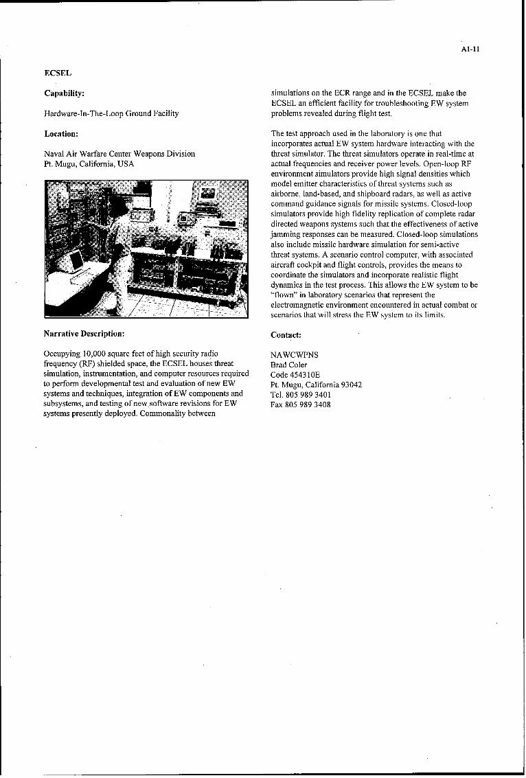
Al-1l
ECSEL
Capability: simulations on the ECR range and in the ECSEL make theECSEL an efficient facility for troubleshooting EW system
Hardware-In-The-Loop Ground Facility problems revealed during flight test.
Location: The test approach used in the laboratory is one thatincorporates actual EW system hardware interacting with the
Naval Air Warfare Center Weapons Division threat simulator. The threat simulators operate in real-time atPt. Mugu, California, USA actual frequencies and receiver power levels. Open-loop RF
environment simulators provide high signal densities whichmodel emitter characteristics of threat systems such asairborne, land-based, and shipboard radars, as well as activecommand guidance signals for missile systems. Closed-loopsimulators provide high fidelity replication of complete radardirected weapons systems such that the effectiveness of activejamming responses can be measured. Closed-loop simulationsalso include missile hardware simulation for semi-activethreat systems. A scenario control computer, with associatedaircraft cockpit and flight controls, provides the means tocoordinate the simulators and incorporate realistic flightdynamics in the test process. This allows the EW system to be"flown" in laboratory scenarios that represent theelectromagnetic environment encountered in actual combat orscenarios that will stress the EW system to its limits.
Narrative Description: Contact:
Occupying 10,000 square feet of high security radio NAWCWPNSfrequency (RF) shielded space, the ECSEL houses threat Brad Colersimulation, instrumentation, and computer resources required Code 45431 OEto perform developmental test and evaluation of new EW Pt. Mugu, California 93042systems and techniques, integration of EW components and Tel. 805 989 3401subsystems, and testing of new software revisions for EW Fax 805 989 3408systems presently deployed. Commonality between

Al-12
INTEGRATED FACILITY FOR AVIONICS TEST (IFAST)
Capability: disciplined test process.
Hardware-in-the-Loop Facility Capability Summary:
Location: * Six shielded bays for avionics spread bench testing.
Edwards Air Force Base, CA * Single and multiple sub-system and integrated offensiveand defensive avionics testing.
Narrative Description:Radar jamming--signal insertion and external
IFAST provides six weapons system specific laboratories, transmission (fixed and airborne pods) for defensiveEach of the labs or bays is configured to provide a combined avionics transmission and reception.software integration and hardware-in-the-loop environmentfor a particular platform such as B-1B, F-16, or F-22. These Contact:bays are used to perform radar and integrated avionics groundtest and evaluation to verify functional performance, avionics Mr. Dennis Hinesand weapons integration, and software changes. 412 TW/EWW
30 Hoglan Ave.Each bay is individually shielded, with isolated electrical Edwards AFB, California 93524-6843power and physical security controls. These features permit DSN: 527-5404 ortesting and development of the most sensitive EW Commercial: (661) 277-5404capabilities. Its location, adjacent to the flight line at Edwards Email: [email protected], California, fosters the use of an organized and

A1-13
INSTALLED SYSTEM TEST FACILITIES
HERF TEST FACILITY
Capability: a A wooden rotating and lifting platform for the transferof heavy large test items into homogeneous zones of the
Installed System Test Facility horizontally polarized electromagnetic fields;
Location: a HERF resistant multipurpose probes and dataacquisition units for installation into the test item as
Daimler-Benz Aerospace required by the customer;
Manching, Germany 0 HERF resistant signal converters for Fiber Optic Link
(FOL) for the transmission of all standard data busNarrative Description: systems; and
As a result of recent an extensive investigations on aircraft An RF shielded laboratory with all necessary fiber opticRF hardness with conventional but inadequate test methods, link front ends, computer networks, 500 MB hard disk,MBB developed an efficient RF illumination test site for the quick look facilities, and recording systems.most problematic High Frequency (HF) range, which allowsrealistic full threat RF susceptibility tests of large test items. Electromagnetic Field Characteristic
The basic elements of the High Energy Radiated The test range is able to generate almost homogenous highElectromagnetic Fields (HERF) Test Site include: density plan waves corresponding to the actual RF threat
conditions for fixed wing aircraft and helicopters or any" An RF signal generator feeding a 100kW linear RF other object passing powerful HF broadcast stations or
amplifier (5-30 MHz) for all kinds of modulations; equivalent RF sources. Computer graphics of all relevantelectromagnetic field parameters as they are distributed over
" Three high power broad-band antennas for the the test volume can be made available for any irradiationgeneration of horizontally and vertically polarized situation.electromagnetic fields in the frequency range 5-30 MHz;
Capabilities Overview
Frequency range 5-30 MHzHigh energy radiated electromagnetic field strength 150 VimDistance between test volume center and radiating antenna > 0/2Max. test item volume for:0 Vertically polar. HERF test site 40 x 35 x 12 m (L x W x H)M Horizontally polar. HERF test site 20 x 15 x 6 m (L x W x H)
RF SourceM Max. RF output power 100 kWa Modulation any kindMax. height of rotating and lifting platform of the horizontally 20mpolarized HERF test siteMax. weight of the test item on the platform 300 kN
Contact:
Messerschmitt-Bolkow-Blohm GmbHAircraft DivisionP.O. Box 1149D-8072 ManchingGermanyPhone: (08459) 81-4117Fax: (08459) 81-4947

A1-14
ACETEF
Capability: realistic (anechoic, or "no echo") test environment for systemstimulation.
Installed System Test FacilityElectronic Warfare Integrated Systems Test Laboratory
Location: (EWISTL) - The EWISTL is an open loop, radio frequencygenerating facility used primarily to stimulate aircraft
Naval Air Warfare Center Aircraft Division Patuxent River, electronic warfare (EW) systems. The facility can simulate upMaryland, USA to 1024 threat radar systems. These radar systems can be
located on up to 26 moving platforms to simulate surfaceNarrative Description: combatants, aircraft, or missile systems. EWISTL has the
unique capability of providing "threat rich" environments thatACETEF is a fully integrated ground test facility which approximate the threat densities envisioned in actual combatsupports test and evaluation of highly integrated aircraft and scenarios. Modifications to the EWISTL currently underwayaircraft systems in a secure and controlled engineering will incorporate portable and millimeter wave open loopenvironment. The facility uses state-of-the-art simulation and simulators, jammer simulators, communications environmentsimulation techniques to provide test scenarios which stimulation, additional background environment simulation,reproduce conditions approaching actual combat. In and missile launch simulators.ACETEF, a fully integrated weapons system, incorporatingvehicle, avionics weapons, crew, other platforms, and critical Closed Loop Threat Facility (CL) - The Closed Loopelements of the operational command/control hierarchy can facility provides specific simulations of a few threat systemsbe immersed in a simulated environment that deceives both to a very high level of fidelity. These systems allow test assetthe aircraft and flight crew into believing that they are in countermeasures to be coupled back into the threat foractual combat. Aircraft systems are deceived through a determinations of effectiveness. Two specific closed loopcombination of simulation by digital computers and systems are now operational in the Closed Loop. Closed Loopsimulation by computer controlled environment generators is linked to EWISTL in real-time.that provide radio frequency, electro-optical stimuli whichduplicate, as closely as possible, real signals. The flight crew Contact:is provided very high fidelity visual, aural, and tacticalworkload. The following paragraphs give a brief description Dan Maconeof the ACETEF subprogram elements. NAWCAD
CODE 510000AAnechoic Test Facility - The current NAWCAD anechoic Atlantic Ranges and Facilitiestest facility is a tactical aircraft size chamber (100 ft. X 60 ft. Building 2109 Suite N220X 40 ft.). The aircraft or system under test is suspended in the 48150 Shaw Rd.chamber in a configuration representing actual flight Patuxent River, Maryland 20670conditions. The chamber provides a secure (over 100dB) and 301-342-6009

A1-15
BENNEFIELD ANECHOIC FACILITY (BAF)
Capability: The BAF has three threat sites (TS) that house the currentthreat generation systems. TS 1 houses the Combat
Installed System Test Facility Electromagnetic Environment Simulator (CEESIM) 8000 and14 RF channels. TS 2 and 3 each house two remote CEESIM
Location: 8000 controlled channels and one hybrid threat simulator.Some threat generation capabilities are:
Edwards Air Force Base, California, USAa Simulates surface based, sea based, and airborne RF
Narrative Description: threat system signals.
The BAF provides realistic, free-space RF environment for * Generates in excess of 64 million pulses per secondevaluation of both uninstalled and installed, federated and (MPPS).integrated avionics, and electronic combat systems onsingle/multiple host platforms. 0 Generates 3-5 MPPS in a coordinated coherent scenario.
Capability Summary: • Simulates 640 emitters simultaneously at the digital level.
* The BAF is DoD's largest anechoic chamber (250' x 264' 0 22 RF hardware channels (22 instantaneous RF signals).x 70') collocated with air vehicle modeling/simulation(TEMS) and systems integration laboratories (IFAST). 0 Simulate eight time-coincident beams.
* In excess of 130 dB of isolation/attenuation from the 0 Various pulse repetition intervals and pulse widths.outside world.
• Various frequency modulations.* 115 VAC 400 Hz/1.15 VAC 60 Hz/480 VAC 60Hz
power. 0 Various scan and antenna patterns.
0 Aircraft cooling and hydraulics. • Terrain occlusion.
• Monitoring/recording of two Pulse Code Modulated and * Updates eight channels each microsecond.five MIL-STD 1553B mux bus data streams.
Contact:* An 80-foot diameter turntable and two 40-ton man-rated
hoists. The turntable is capable of rotating in excess of a Mr. Dennis Hines250,000 pound test article 380 degrees (+/- 190 degrees) 412 TW/EWWwith a 0.1 degree positional accuracy. The turntable is 30 Hoglan Ave.capable of rotating at rates varying from 0.1 degrees per Edwards AFB, California 93524-6843second to 0.6 degrees per second. The 40-ton man-rated DSN: 527-5404 orhoists are capable of lifting and rotating test articles as Commercial: (661) 277-5404high as 55 feet above the floor of the facility. Email: [email protected]
A1-16
OPEN AIR RANGE
HYPERBRAHMS
Capability: Main Parameters
Flight Test ground station * Simultaneous measurement in seven frequency bandsbetween 0.5 and 38 GHz in l0-kHz steps
Location:. Dual polarization (H and V) transmission, 14
Flight test Centre measurement channels in receive mode
Bretigny, France * 10 measurement channels in pulse mode (2 to 18 GHzand 32 to 38 GHz) in 3.3 -ns to 10 pulses (minimum
Narrative Description range resolution: 50 cm)
HYPERBRAHMS measures the Radar Cross Section (RCS) * Power requirements: three-phase 380V 1 IOkVAof aircraft, ships, or land vehicles.
Contact:HYPERBRAHMS can perform an analysis of the Dopplersignatures, the characterization of electromagnetic decoys, Flight Test Centreand an analysis of the capabilities ofjammers. The system has Bretignya real-time processing capability allowing the tests to be Tel. (33) 01 69 88 25 20validated immediately with finer processing available in nonreal-time. The systems' antenna can be designated externally.HYPERBRAHMS can be set up by three operators with anon-site installation time of 2 to 4 days.
Al-17
HYPERCERBERE
Capability Speed: 2 rad/s
Flight test ground station Acceleration: 8 rad/s
Location Equipped weight: 900kg
Flight Test Centre • Measurement sensors:
Btetigny, France Band 1, 11, III radiation meters (1.5 to 14.5 mm)
Narrative Description Band II thermal imaging camera
HYPERCERBERE is a ground station for acquisition and pre- (2.5 to 5.2 mm).processing of measurements of the infrared (IR) radiationemitted by air targets. HYPERCERBERE consists of an air- • Equipment:transportable shelter with a measurement compartment andturret room: length: 8m, weight: 7 t. One real-time supervision computer
By measuring the IR signature, HYPERCERBERE is used to Three VME-based computersenhance the performance and stealth characteristics ofairborne weapon systems to improve their effectiveness and Turret controlprovide them with improved survival capability in operation.It can also be used to correct radiation models by precisely Measurement acquisitionidentifying the IR signature of the target as seen by theweapon system as well as to enhance the performance Image processingcharacteristics of self-protection systems.
There are internal and external ETHERNET networks forMain performance characteristics: non-real-time data transmission to CEV station (MATISSE
network).* Turret:
Contact:Traverse clearance: 360o
FLIGHT TEST CENTREElevation clearance: -5o and +90o Bretigny, France
Tel. (33) 01 69 88 25 20
Al-18
THE ANTI-RADAR MISSILE AIRBORNE DATA ANALYSIS SYSTEM (ARMADAS)
Capability: instrumented ranges, against any target of opportunity, andcan therefore be operated during normal military exercise in
RF Threat Simulator order to obtain results from realistic complex scenarios.
Location: Additional modes of control are manual steering of the pod,and finally, suitably processed signals from the microwave
DERA, Farnborough, UK receiving equipment itself.
Narrative Description: The Tracker system receives data from the TV cameramounted in the steerable pod. The operator identifies the
ARMADAS's primary function is the recording and analysis object to be tracked in the first instance by steering the podof the emission characteristics of modem complex radar manually if necessary and selecting the target on the TVsystems and multi-path effects within their operational monitor. The tracker will then steer the pod so as to maintainenvironment. the target on the boresight of the TV camera. The scene from
the camera is recorded using the VCR and the picture isThe equipment is installed in an Andover with the microwave overlaid with various markers indicating parameters such asreceiving antenna mounted in a stabilized steerable pod boresight and tracked object position. If the tracker is unablemounted in the nose of the aircraft. The pod also contains a to track the target, then it is possible to steer the pod usingTV camera which feeds a tracking system and TV monitor data from the PC which calculates the position by using thewithin the aircraft. This allows the, pod to be aligned with the data from the GPS input and the aircraft data. ARMADAS hastarget by a number of alternative methods. The principal been recently upgraded by the addition of a narrow bandmethod is by the TV camera and optical tracker maintaining signal demodulator and a differential GPS system to providethe target radar in the center of the image. accurate time and position references.
The direction of the line of sight to the target aircraft is Contact:calculated by knowing the position of the Andover aircraftfrom its navigation system and the target aircraft from a GPS Mr. C.T.Moffatt and Mr. A.T.Hill,system. The pod is then steered to the desired line of sight. Defence Evaluation and Research Agency,This facility allows the system to operate independently of Farnborough, UK
A1-19
THE ACTIVE MULTIPLE RADAR SIMULATION SYSTEM (MEDUSA)
Capability: The primary system components of MEDUSA are:
RF Threat Simulator a three dish antennae and turntables;
Location: * multiple hardware (PROM) or software (FURIES)programmable pulse generators;
DERA, Farnborough, UK. multiple RF sources, modulators and amplifiers (up to 4
Narrative Description: kW);
MEDUSA is a self-contained mobile laboratory for the 0 signal monitoring equipment including power meters,transmission of medium to high power RF signals between spectrum analyzer, and oscilloscopes;0.5 to 18 GHz. Its purpose is to generate test and simulatedradar signals in free space during trials. plus various power supplies, and 400 Hz static inverters.
MEDUSA contains RF simulation, distribution, and Contact:transmission and monitoring hardware. It can generate ERPscapable of exercising the full dynamic range of receivers at Mr. C.T.Moffatt and Mr. A.T.Hill,short ranges, and capable of detection at ranges beyond Defence Evaluation and Research Agency,10 km on flight trials. All the primary radar characteristics can Farnborough, UKbe simulated, plus engagement sequences and multiplesignals. Linear polarization changes are also possible.
Al-20
ELECTRONIC COMBAT RANGE (ECR)
Capability: In addition to the threat systems, ECR maintains time, space,and position information (TSPI) reference systems, a
Open-Air Range computer and operations center, a telemetry facility, a facilityfor static ground testing and RF monitoring, and a data
Location: processing capability. The ECR has an extensiveinstrumentation infrastructure consisting of fiber optic
Naval Air Warfare Center Weapons Division communications, telemetry reception, recording, and anChina Lake, California, USA extensive real-time presentation of audio, video, and digital
data for monitoring the execution of tests involving the threatNarrative Description: systems. These data are collected in a central location on the
range and presented collectively in the Test OperationsThe ECR provides a comprehensive electronic warfare (EW) Center. The Operations Center interfaces with data collectingstand-alone test environment and permits multiple tests to be and video recording systems, allowing a test to be controlledconducted concurrently. The ECR provides realistic and monitored by a test operations team and customerrepresentations of Russia and ROW air defense systems and representatives. The Operations Center includes a digitalinstrumentation for test and evaluation of electronic warfare display system to permit range users to view real-time datasystems, devices, and tactics. The ECR performs EW tests to including tracking errors, radar status data, missile interceptsupport exploratory development, engineering development, data, and gun system lethality. Video displays are available totechnical and operational evaluations, and training. In view visual images from cameras mounted on the threataddition, live fire tests can be conducted in coordination with system antenna pedestals. In addition, various radar displaysthe other ranges at the China Lake Complex. The ECR are available including type-A, type-B3, and Plan Positioncontains both shipboard and land-based air defense threats as Indicator (PPI) displays. The data are recorded and availablewell as blue and gray systems. immediately to the user and post-test data processing team.
Reference systems at ECR include Nike target tracking radarsECR currently provides numerous threat simulator and real and the Global Positioning based TSPI System. In addition,world systems of various types employing a large spectrum of laser, optical, and IR tracking systems can be obtained fortechnologies and techniques employed in radar system design specific tests from other organizations at China Lake.including multi-object tracking phased array designs. All ofthese systems are instrumented with audio and video Contact:instrumentation and a number of the systems are instrumentedto collect extensive digital data about the operation of the NAWCWPNS: Chuck Mattsonsystems. The Command and Control (C2) system can be used Code 52C000Dto control the operation of the threat simulations as they China Lake, California 93555would be operated if they were part of an integrated air Tel. (760) 939-9206defense network. The ECR C2 systems enable various Fax (760) 939-9212combinations of the ECR's numerous air defense assets to Email: chuck-mattson@echo~chinalake.navy.milrepresent surface and naval air-defense systems found aroundthe world.

A1-21
MODELING AND SIMULATION
LIGASE
Capability: CSF/RCM and TTD, Matra Defense, GIE RBE2, SAT. Forreasons of industrial confidentiality, no manufacturer has
Laboratory Digital Model access to the models developed by the other contractors.
Location: LIGASE is a host structure composed of a model managementcore and an MMI (Man Machine Interface). Models exist for
le Centre D'electronique De L'armement(CELAR) the environment, radar, radar warning receiver, jammer,Rennes, France aircraft, target, and missile. Various activation modes are
batch, statistical, and interactive. The management coreNarrative Description: governs the models' temporal activation and data interchange.
The models are written in Fortran, C, and C++. The MMILIGASE is a response to problems encountered in integrating allows simulation to be controlled while displaying systema group of models within an armament system. This software status through overviews or cut-out views such as a radarallows system status to be interactively prepared and display, an infrared picture, or an alert detection display fromvisualized for analytical purposes in the course of time. a workstation.LIGASE allows findings from various simulations of one andthe same case to be processed for statistical use. Contact:
The digital simulations of MICA fire control systems in CELARMIRAGE 2000-5 and RAFALE aircraft were instrumental in GEOS/MPEcausing this software tool to be produced. The models Ipa Rabiercomprising the fabric of the system are the responsibility of Tel. (33) 2 99 42 90 40different manufacturers: Dassault Aviation, Thomson- Fax (33) 2 99 42 90 92

Al-22
VHEDAA
Capability: reaction (rerouting, evasion) and its trajectory (very lowaltitude flight, map-of-the-earth flight).
Laboratory digital modelSelection of a threat: infrared, electromagnetic coupled with
Location: a missile or a gun. The threat is modeled with a high level ofaccuracy; validated models are included, such as seekers and
CELAR radars, which enable the user to carry out efficiency studies inGEOS an electronic warfare environment. Each integrated threat hasBruz, France its own system behavior and all the targets for system
engagement states. The user can control all the steps ofNarrative Description: acquisition and tracking; the scene projected on the field of
view of the seeker can be seen during the simulation. TheThe VHEDAA application is a study environment for signal-to-noise ratio is computed, as is the radiance for thehelicopter vulnerability using simulation tools and statistical infrared seeker.computation. Helicopters are characterized by their ability totake advantage of the protection provided by geographical The methodology: a realistic scenario in a multiple-threatrelief and micro-relief against the threats placed in an environment or duel configurations between the helicopteroperational environment. They represent an effective tool to and the chosen threat with a view to establishing aget closer to the target while keeping hidden from the comprehensive statistical study are available.potential surface-to-air threat (optical, infrared,electromagnetic). Helicopter vulnerability studies have to take Two types of studies can be conducted with VHEDAA: aninto account these specific behavior patterns and to deal as operational scenario or statistical. Both solutions aremuch as possible with digitized maps; the interrelationships complementary and allow the blanks left by either one to bebetween the threat and the helicopter, nap-of-the earth flights covered by the other. The operational study aims at a highand so on. This constraint, which is not sufficiently degree of realism in a tactical scenario. The helicopter has aemphasized in aircraft studies, needs to constantly control the mission and has to face numerous threats of different types.interaction of each involved "object" (helicopters, threats, All the criteria are defined, including number, types, andprojectiles, flares) with the ground environment. VHEDAA positions of threats. The precise trajectory is defined by aallows the user to do this. computer model or by pilots in a helicopter-man- in-the- loop
simulator. This study enables the user to make a preciseA man-machine interface allows the user to create a scenario vulnerability study, the results of which are not applied toon a digitized map easily (either a genuine map or one another configuration. These results are useful to validate aobtained by the user from a statistical model). The definition concept. The statistical study has been defined to avoid theof the scenario is established by selecting the starting and dependence of the results obtained with the operational study.destination points for the helicopter's trajectory and after that The aim of the study is to get results such as delectability orthe number and type of threats involved in the scenario. The vulnerability for each helicopter evaluation without having toman-machine interface provides the user with a broad range define the type of map or the position of the threat.of possibilities:
Contact:Selection of the map in a database: statistical or realistic(DLMS altimeter and planimeter). The resolution of a mesh is CELARvariable depending on the need. GEOS/CME
Isabelle LecuyerSelection of the helicopter, the signature and the selfscreening Tel. (33) 2 99 42 95 37system (Radar Warning Receiver, Missile Launch Detector, Fax (33) 2 99 42 90 92Missile Approach Detector, flares, chaffs ... ), selection of its
Al-23
TEST AND EVALUATION MODELING AND SIMULATION FACILITY (TEMS)
Capability: effectiveness of the enemy integrated air defense system, aswell as its susceptibility.
Modeling and Simulation FacilityAt the Engagement level, TEMS has both ESAMS and
Location: JMASS simulations available. These simulations modelengagement level, one-on-one, air-land battle simulations.
Edwards Air Force Base, California,. USA Engagement level metrics include missile and targetflightpaths, detailed end game analysis, and statistically
Narrative Description: analyzed data.
The Test and Evaluation Modeling and Simulation (TEMS) TEMS also provides a full range of virtual, real-time,facility provides constructive, non-real-time and virtual, operator-in-the-loop, simulations ranging from engineeringpiloted real-time simulations. While the primary focus of level, stand-alone, to multiple aircraft simulations linkedTEMS is on support of operational and developmental testing, together to provide a one-on-one engagement or many-on-its utility has been demonstrated throughout the entire many mission level simulations. These simulations offerlifecycle of aerospace systems. TEMS routinely supports support to a wide range of activities that include aircrafttesting, mission rehearsal, training, and analysis for aircraft envelope expansion, EW blue/red man in the loop, anomalyflying qualities, performance, propulsion, avionics, and investigation, incident/accident investigation, missionelectronic warfare. The precise control, flexibility, and rehearsal, and aircrew system familiarization.repeatability of these simulations are paramount inimplementing a predict-test-compare-update philosophy Modeling and Simulation verification and validation is anleveraging knowledge gained through ground testing before integral part of TEMS' configuration management plan.implementing a flight test methodology. Correlation and consistency of data are paramount to achieve
the highest fidelity of models and simulations. The ultimateThe full range of constructive, non-real-time simulations source of validation data is open-air range data and TEMS,ranging from Campaign to Mission, Engagement, and being part of the overall test process, is uniquely postured toEngineering levels is supported by TEMS. Based on customer incorporate actual flight test data to update models. In thisneeds, TEMS can model a myriad of simulations focusing on way, the model and simulations achieve "real-world" -different types of evaluations. TEMS can model a multi-day, validation that is mandatory in today's test and evaluationtheater level campaign, simulating force-on-force, air-land environment.battle using the THUNDER model.
Contact:Where mission level metrics are required, TEMS has theability to model air superiority and survivability to simulate a Mr. Dennis Hinesmany-on-many, air-land battle using SUPRESSOR and 412 TW/EWWDIADS. SUPRESSOR allows the capability to evaluate 30 Hoglan Ave.mission level metrics such as effects due to weapon and Edwards AFB, California 93524-6843sensor systems, tactics, command and control vulnerabilities, DSN: 527-5404 orand susceptibility to countermeasures. DIADS uniquely Commercial: (805) 277-5404provides users with a tool for the evaluation of the Email: [email protected]
A2-1
Annex 2
AGARD Flight Test Instrumentation and Flight Test Techniques Series
1. Volumes in the AGARD Flight Test Instrumentation Series, AGARDograph 160
Volume Title PublicationNumber Date1. Basic Principles of Flight Test Instrumentation Engineering (Issue 2)
Issue 1: edited by A. Pool and D. Bosman 1974Issue 2: edited by R. Borek and A. Pool 1994
2. In-Flight Temperature Measurements 19733. by F. Trenkle and M. Reinhardt
3. The Measurements of Fuel Flow 1972by J.T. France
4. The Measurements of Engine Rotation Speed 1973by M. Vedrunes
5. Magnetic Recording of Flight Test Data 1974by G.E. Bennett
6. Open and Closed Loop Accelerometers 1974by I. Mclaren
7. Strain Gauge Measurements on Aircraft 1976by E. Kottkamp, H. Wilhelm and D. Kohl
8. Linear and Angular Position Measurement of Aircraft Components 1977by J.C. van der Linden and H.A. Mensink
9. Aeroelastic Flight Test Techniques and Instrumentation 1979by J.W.G. van Nunen and G. Piazzoli
10. Helicopter Flight Test Instrumentation 1980by K.R. Ferrell
11. Pressure and Flow Measurement 1980by W. Wuest
12. Aircraft Flight Test Data Processing - A Review of the State of the Art 1980by L.J. Smith and N.O. Matthews
13. Practical Aspects of Instrumentation System Installation 1981by R.W. Borek
14. The Analysis of Random Data 1981by D.A. Williams
15. Gyroscopic Instruments and their Application to Flight Testing 1982by B. Stieler and H. Winter
16. Trajectory Measurements for Take-off and Landing Test and Other Short-Range 1985Applications
by P. de Benque D'Agut, H. Rielmek and A. Pool
17. Analogue Signal Conditioning for Flight Test Instrumentation 1986by D.W. Veatch and R.K. Bogue
18. Microprocessor Applications in Airborne Flight Test Instrumentation 1987by M.J. Prickett
19. Digital Signal Conditioning for Flight Test 1991by G.A. Bever

A2-2
2. Volumes in the AGARD Flight Test Techniques Series
Volume Title PublicationNumber Date
AG237 Guide to In-Flight Thrust Measurement of Turbojets and Fan Engiies by the MIDAP 1979Study Group (UK)
The remaining volumes are published as a sequence of Volume Numbers of AGARDograph 300.
Volume Title PublicationNumber Date
I Calibration of Air-Data Systems and Flow Direction Sensors 1988by J.A. Lawford and K.R. Nippress
2. Identification of Dynamic Systems 1988by R.E. Maine and K.W. Iliff
4. Identification of Dynamic Systems - Applications to Aircraft5. Part 1: The Output Error Approach 1986
by R.E. Maine and K.W. Iliff
Part 2: Nonlinear Analysis and Manoeuvre Design 1994by J.A. Mulder, J.K. Sridhar and J.H. Breeman
4. Determination of Antenna Patterns and Radar Reflection Characteristics of Aircraft 1986by H. Bothe and D. McDonald
5. Store Separation Flight Testing 1986by R.J. Arnold and C.S. Epstein
6. Developmental Airdrop Testing Techniques and Devices 1987by H.J. Hunter
7. Air-to-Air Radar Flight Testing 1992by R.E. Scott
8. Flight Testing under Extreme Environmental Conditions 1988by C.L. Henrickson
9. Aircraft Exterior Noise Measurement and Analysis Techniques 1991by H. Heller
10. Weapon Delivery Analysis and Ballistic Flight Testing 1992by R.J. Arnold and J.B. Knight
11. The Testing of Fixed Wing Tanker & Receiver Aircraft to Establish their 1992Air-to-Air Refuelling Capabilities
by J. Bradley and K. Emerson
12. The Principles of Flight Test Assessment of Flight-Safety-Critical Systems in Helicopters 1994by J.D.L. Gregory
13. Reliability and Maintainability Flight Test Techniques 1994by J.M. Howell
14. Introduction to Flight Test Engineering 1995Edited by F. Stoliker
15. Introduction to Avionics Flight Test 1996by J.M. Clifton
16. Introduction to Airborne Early Warning Radar Flight Test 1999by J.M. Clifton and F.W. Lee
17. Electronic Warfare Test and Evaluation 1999by H. Banks and R. McQuillan

A2-3
At the time of publication of the present volume the following volumes were in preparation:
Flying Qualities Flight Testing of Digital Flight Control Systemsby F. Webster
Flight Testing of Missilesby Taylor and Guerrini
Flight Testing of Night Vision Systemsby J. Dumoulim
Flight Testing of Radio Navigation Systemsby H. Bothe and H.J. Hotop
Simulation in Support of Flight Testingby D. Hines
Rotorcraftl/Ship Compatibility Testingby W. Geyer Jr, R. Finch, R. Fang, D. Carico, K. Long and H.W. Krijns
Flight Test Measurement Techniques for Laminar Flowby Horstman nad D. Fisher
The Integration of Logistics Test and Evaluation in Flight Testingby M. Bourcier
REPORT DOCUMENTATION PAGE
1. Recipient's Reference 2. Originator's References 3. Further Reference 4. Security Classificationof Document
RTO-AG-300 ISBN 92-837-1034-7 UNCLASSIFIED/AC/323(SCI)TP/24 UNLIMITEDVolume 17
5. Originator Research and Technology OrganizationNorth Atlantic Treaty OrganizationBP 25, 7 rue Ancelle, F-92201 Neuilly-sur-Seine Cedex, France
6. TitleElectronic Warfare Test and Evaluation
7. Presented at/sponsored by
the Systems Concepts and Integration Panel (SCI) of RTO.
8. Author(s)/Editor(s) 9. Date
H. Banks March 2000R. McQuillan
10. Author's/Editor's Address 11. Pages
Multiple 88
12. Distribution Statement There are no restrictions on the distribution of this document.Information about the availability of this and other RTOunclassified publications is given on the back cover.
13. Keywords/Descriptors
Electronic warfare Electronic countermeasuresElectromagnetic spectra CountercountermeasuresFlight tests Computerized simulationPerformance evaluation Test facilitiesElectronic support measures Models
14. Abstract
The past decade has seen an enormous increase in the use and importance of the "electronicbattlefield." As a result of the continuing growth in this area, this volume has been prepared toserve as an introductory reference to the process of testing and evaluating Electronic WarfareSystems. Electronic Warfare (EW) is the mission area responsible for establishing andmaintaining a favorable position in the electromagnetic domain.
Test and evaluation (T&E) of those devices used on modem military aircraft to prosecute thiscritical mission area requires the use of a wide range of test techniques and analytical methodsto assure users of the readiness of EW systems to meet the challenges of the combatenvironment. Actual in-flight testing comprises a relatively small portion of the EW T&Eprocess. Today's tester makes judicious use of a plethora of models, simulations, and hardware-in-the-loop test facilities prior to and during the more realistic open-air range and installedsystem test facility events. Analysis of data derived from each of these test opportunities leadsto the overall evaluation of the EW system.
This volume will introduce the concept of the EW Test Process and subsequently show how itis applied in each class of test facility and to each major division of EW systems. The readerwill find that the concentration in this document is far broader than "flight test" - ranging fromlaboratory efforts to establish the system performance baseline through complex ground-basedsimulations and finally the limited, but vitally important, verification accomplished in the open-air range environment.

NORTH ATLANTIC TREATY ORGANIZATION
RESEARCH AND TECH-NO OcVY ORGANIZATION
BP 25 * 7 RUE ANCELLE DIFFUSION DES PUBLICATIONSF-92201 NEUILLY-SUR-SEINE CEDEX * FRANCE RTO NON CLASSIFIEES
Tel6copie 0(1)55.61.22.99 • E-mail mailbox@ rta.nato.int
L'Organisation pour la recherche et la technologie de I'OTAN (RTO), d~tient un stock limnit6 de certaines de ses publications rncentes, ainsique de celles de l'ancien AGARD (Groupe consultatif pour la recherche et les r~alisations a~rospatiales de 1'OTAN). Celles-ci pourront6ventuellement &tre obtenues sous forme de copie papier. Pour de plus amples renseignements concernant l'achat de ces ouvrages,adressez-vous par lettre ou par t41icopie A l'adresse indiqu~e ci-dessus. Veuillez ne pas til1phoner.
Des exemplaires supplbmentaires peuvent parfois &tre obtenus auprbs des centres nationaux de distribution indiqu~s ci-dessous. Si voussouhaitez recevoir toutes les publications de ]a RTO, ou simplement celles qui concernent certains Panels, vous pouvez demander d'&treinclus sur la liste d'envoi de l'un de ces centres.
Les publications de la RTO et de I'AGARD sont en vente aupr~s des agences de vente indiqu~es ci-dessous, sous forme de photocopie oude microfiche. Certains originaux peuvent 6galement 6tre obtenus aupr~s de CASI.
CENTRES DE DIFFUSION NATIONAUX
ALLEMAGNE FRANCE PAYS-BASStreitkrafteamt / Abteilung III O.N.E.R.A. (ISP) NDRCCFachinformationszentrum der 29, Avenue de la Division Leclerc DGM/DWOOBunderswehr, (FIZBw) BP 72, 92322 Ch5tillon Cedex P.O. Box 20701
Friedrich-Ebert-Allee 34 2500 ES Den HaagD-53113 Bonn GRECE (Correspondant)Hellenic Ministry of National POLOGNE
BELGIQUE Defence Chief of International CooperationCoordinateur RTO - VSL/RTO Defence Industry Research & DivisionEtat-Major de la Force Adrienne Technology General Directorate Research & Development DepartmentQuartier Reine Elisabeth Technological R&D Directorate 218 Niepodleglosci Av.Rue d'Evbre, B-1140 Bruxelles D.Soutsou 40, GR-1 1521, Athens 00-911 Warsaw
CANADA HONGRIE PORTUGALDirecteur - Recherche et ddveloppement - Department for Scientific Estado Maior da Forga A~reaCommunications et gestion de Analysis SDFA - Centro de Documentay-dol'information - DRDCGI 3 Institute of Military Technology Alfragide
Ministbre de la Defense nationale Ministry of Defence P-2720 AmadoraOttawa, Ontario KIA 0K2 H-1525 Budapest P 0 Box 26 REPUBLIQUE TCHEQUE
DANEMARK ISLANDE VTOL a PVO Praha /Danish Defence Research Establishment Director of Aviation Air Force Research Institute PragueRyvangs All 1, P.O. Box 2715 c/o Flugrad Ndirodni informamnf stfediskoDK-2100 Copenhagen 0 Reykjavik obranndho v~zkumu (NISCR)
ESPAGNE ITALIE MladoboleslavskA ul., 197 06 Praha 9
INTA (RTO/AGARD Publications) Centro documentazione ROYAUME-UNICarretera de Torrej6n a Ajalvir, Pk.4 tecnico-scientifica della Difesa Defence Research Information Centre28850 Torrej6n de Ardoz - Madrid Via Marsala 104 Kentigern House
ETATS-UNIS 00185 Roma 65 Brown Street
NASA Center for AeroSpace LUXEMBOURG Glasgow G2 8EX
Information (CASI) Voir Belgique TURQUIEParkway Center NORVEGE Milli Savunma Ba~kanligi (MSB)7121 Standard Drive Norwegian Defence Research ARGE Dairesi Ba~kanligi (MSB)Hanover, MD 21076-1320 Establishment 06650 Bakanliklar - Ankara
Attn: BiblioteketP.O. Box 25, NO-2007 Kjeller
AGENCES DE VENTE
NASA Center for AeroSpace The British Library Document Canada Institute for Scientific andInformation (CASI) Supply Centre Technical Information (CISTI)
Parkway Center Boston Spa, Wetherby National Research Council7121 Standard Drive West Yorkshire LS23 7BQ Document DeliveryHanover, MD 21076-1320 Royaume-Uni Montreal Road, Building M-55Etats-Unis Ottawa KIA 0S2, Canada
Les demandes de documents RTO ou AGARD doivent comporter la denomination "RTO" ou "AGARD" selon le cas, suivie dunumdro de s~rie (par exemple AGARD-AG-315). Des informations analogues, telles que le titre et la date de publication sontsouhaitables. Des r~fdrences bibliographiques compl~tes ainsi que des r6sumds des publications RTO et AGARD figurent dans lesjournaux suivants:
Scientific and Technical Aerospace Reports (STAR) Government Reports Announcements & Index (GRA&I)STAR peut &tre consult6 en ligne au localisateur de publi6 par le National Technical Information Serviceressources uniformes (URL) suivant: Springfield
http://www.sti.nasa.gov/Pubs/star/Star.html Virginia 2216STAR est 6dit6 par CASI dans le cadre du programme Etats-UnisNASA d'information scientifique et technique (STI) (accessible 6galement en mode interactif dans la base deSTI Program Office, MS 157A donn~es bibliographiques en ligne du NTIS, et sur CD-ROM)NASA Langley Research CenterHampton, Virginia 2368 1-0001Etats-Unis r
hnprind par le Groupe Communication Canada Inc.(membre de la Corporation St-Joseph)
45, boul. Sacr,ý-Cceur, Hull (Quebec), Canada KiA 0S7
NORTH ATLANTIC TREATY ORGANIZATION
RESEARCH AND TECHNOLOGY ORGANIZATION
BP 25 * 7 RUE ANCELLE DISTRIBUTION OF UNCLASSIFIED
F-92201 NEUILLY-SUR-SEINE CEDEX * FRANCE RTO PUBLICATIONS
Telefax 0(1)55.61.22.99 e E-mail mailbox@ rta.nato.int
NATO's Research and Technology Organization (RTO) holds limited quantities of some of its recent publications and those of the formerAGARD (Advisory Group for Aerospace Research & Development of NATO), and these may be available for purchase in hard copy form.For more information, write or send a telefax to the address given above. Please do not telephone.
Further copies are sometimes available from the National Distribution Centres listed below. If you wish to receive all RTO publications, orjust those relating to one or more specific RTO Panels, they may be willing to include you (or your organisation) in their distribution.
RTO and AGARD publications may be purchased from the Sales Agencies listed below, in photocopy or microfiche form. Original copiesof some publications may be available from CASI.
NATIONAL DISTRIBUTION CENTRES
BELGIUM GREECE (Point of Contact) POLANDCoordinateur RTO - VSL/RTO Hellenic Ministry of National Chief of International CooperationEtat-Major de la Force A6rienne Defence DivisionQuartier Reine Elisabeth Defence Industry Research & Research & DevelopmentRue d'Evbre, B- 1140 Bruxelles Technology General Directorate Department
Technological R&D Directorate 218 Niepodleglosci Av.CANADA D.Soutsou 40, GR-11521, Athens 00-911 WarsawDirector Research & Development
Communications & Information HUNGARY PORTUGALManagement - DRDCIM 3 Department for Scientific Estado Maior da Forqa A6rea
Dept of National Defence Analysis SDFA - Centro de Documentaq5oOttawa, Ontario K1A 0K2 Institute of Military Technology Alfragide
Ministry of Defence P-2720 AmadoraCZECH REPUBLIC H-1525 Budapest P 0 Box 26
VTIOL a PVO Praha I SPAINAir Force Research Institute Prague ICELAND INTA (RTO/AGARD Publications)
Ndrodnf informa~nf st-edisko Director of Aviation Carretera de Torrej6n a Ajalvir, Pk.4obrann6ho v~zkumu (NISiR) c/o Flugrad 28850 Torrej6n de Ardoz - Madrid
Mladoboleslavskd ul., 197 06 Praha 9 Reykjavik TURKEY
DENMARK ITALY Milli Savunma Baýkanligi (MSB)Danish Defence Research Centro documentazione ARGE Dairesi Ba~kanligi (MSB)
Establishment tecnico-scientifica della Difesa 06650 Bakanliklar - AnkaraRyvangs Al11 1, P.O. Box 2715 Via Marsala 104DK-2100 Copenhagen 0 00185 Roma UNITED KINGDOM
Defence Research InformationFRANCE LUXEMBOURG Centre
O.N.E.R.A. (ISP) See Belgium Kentigem House29 Avenue de la Division Leclerc 65 Brown StreetBP 72, 92322 Chatillon Cedex NETHERLANDS Glasgow G2 8EX
NDRCCGERMANY DGM/DWOO UNITED STATES
Streitkrhfteamt / Abteilung III P.O. Box 20701 NASA Center for AeroSpaceFachinformationszentrum der 2500 ES Den Haag Information (CASI)
Bunderswehr, (FIZBw) Parkway CenterFriedrich-Ebert-Allee 34 NORWAY 7121 Standard DriveD-53113 Bonn Norwegian Defence Research Hanover, MD 21076-1320
EstablishmentAttn: BiblioteketP.O. Box 25, NO-2007 Kjeller
SALES AGENCIES
NASA Center for AeroSpace The British Library Document Canada Institute for Scientific andInformation (CASI) Supply Centre Technical Information (CISTI)
Parkway Center Boston Spa, Wetherby National Research Council7121 Standard Drive West Yorkshire LS23 7BQ Document DeliveryHanover, MD 21076-1320 United Kingdom Montreal Road, Building M-55United States Ottawa KIA 0S2, Canada
Requests for RTO or AGARD documents should include the word 'RTO' or 'AGARD', as appropriate, followed by the serialnumber (for example AGARD-AG-315). Collateral information such as title and publication date is desirable. Full bibliographicalreferences and abstracts of RTO and AGARD publications are given in the following journals:
Scientific and Technical Aerospace Reports (STAR) Government Reports Announcements & Index (GRA&I)STAR is available on-line at the following uniform published by the National Technical Information Serviceresource locator: Springfield
http://www.sti.nasa.gov/Pubs/star/Star.html Virginia 22161STAR is published by CASI for the NASA Scientific United Statesand Technical Information (STI) Program (also available online in the NTIS BibliographicSTI Program Office, MS 157A Database or on CD-ROM)NASA Langley Research CenterHampton, Virginia 23681-0001United States
Printed by Canada Communication Group Inc.(A St. Joseph Corporation Company)
45 Sacr,ý-Cweur Blvd., Hull (Quebec), Canada K1A 0S7
ISBN 92-837-1034-7