ag2010-01_20100902
TRANSCRIPT

Date Code 20100902 SEL Application Guide 2010-01
Application Guide Volume I AG2010-01
Applying the SEL-421 Relay to Permissive Overreaching Transfer Trip Schemes
Ryan McDaniel
INTRODUCTION The SEL-421 Protection, Automation, and Control System supports all popular communications-assisted tripping schemes. This application guide discusses applying the SEL-421 in permissive overreaching transfer trip (POTT) schemes. With the assistance of a communications channel, the SEL-421 provides high-speed protection for faults located anywhere along the protected transmission line. This application guide includes programming examples and applications specific to the SEL-421. For more information, please refer to the SEL-421 Reference Manual, available at www.selinc.com.
GENERAL PRINCIPLES OF POTT SCHEMES A POTT scheme is a communications scheme in which an asserted overreaching element at the local terminal must receive permission to trip from the remote terminal.
In a POTT scheme, the zones shown in Figure 1 have the following functions:
• Zone 2 has a forward overreaching element that provides communications-assisted tripping for the length of the entire line with margin. When a Zone 2 element asserts, it can only trip a breaker immediately if permission has been received from the remote end. Zone 2 is also used to send a permissive signal to a remote breaker.
• Zone 3 has a reverse-reaching element that overreaches Zone 2 of the remote breaker and blocks sending permission to the remote terminal. Zone 3 elements are used for internal logic in the relay and provide additional POTT scheme security.
Figure 1 Example System One-Line Diagram

2
SEL Application Guide 2010-01 Date Code 20100902
Generally, a Zone 1 element is also set to underreach the remote terminal with margin and is not part of the POTT communications scheme. The function of a Zone 1 element is to provide instantaneous local breaker tripping without communications assistance. However, if a line is short, an acceptable Zone 1 setting may not be possible, and the line will only rely on the POTT scheme for fast line fault detection and clearing.
Line Fault Example For the fault in Figure 1, the relay at Breaker 4 asserts Zone 1 elements to trip instantaneously. Because the fault is also within Zone 2 of the relay, a permissive signal is sent to the relay at Breaker 3. The relay at Breaker 3 asserts Zone 2 elements and trips Breaker 3 once the permissive signal is received from the Breaker 4 relay.
Out-of-Zone Fault Example For a fault that is located between Breakers 5 and 6, the relay at Breaker 3 may still assert a Zone 2 element. However, the Zone 3 elements at Breaker 4 assert and block sending permission to the relay at Breaker 3. This ensures that instantaneous tripping is disabled for out-of-zone faults.

3
Date Code 20100902 SEL Application Guide 2010-01
SEL-421 Relay Elements The zones of protection needed for the POTT scheme can be implemented with distance elements, directional overcurrent elements, or both. The most commonly used relay elements for a POTT scheme are provided in Table 1.
Table 1 Common POTT Relay Elements
Relay Element Protection Zone – Direction
Zone 1 Elements – Forward Reaching
M1P Instantaneous Zone 1 phase mho distance element for nonpilot direct tripping
Z1G Instantaneous Zone 1 ground distance element for nonpilot direct tripping
67G1 Level 1 residual overcurrent element for nonpilot direct tripping
67Q1 Level 1 negative-sequence overcurrent element for nonpilot direct tripping
Instantaneous Timed Zone 2 Elements – Forward Reaching
M2P M2PT Zone 2 phase mho forward distance element for pilot protection logic
Z2G Z2GT Zone 2 ground forward distance element for pilot protection logic
67G2 67G2T Level 2 residual forward overcurrent element for pilot tripping
67Q2 67Q2T Level 2 negative-sequence forward overcurrent element for pilot tripping
Instantaneous Timed Zone 3 Elements – Reverse Reaching
M3P M3PT Zone 3 phase mho reverse distance element for pilot protection logic
Z3G Z3GT Zone 3 ground reverse distance element for pilot protection logic
67G3 67G3T Level 3 residual reverse overcurrent element for pilot protection logic
67Q3 67Q3T Level 3 negative-sequence reverse overcurrent element for pilot protection logic
Enable POTT Logic in the SEL-421 To enable POTT logic in the SEL-421, use the ECOMM setting, summarized in Table 2.
Table 2 Summary of ECOMM Setting for POTT Scheme
Setting ECOMM = Setting Description
POTT Conventional POTT scheme with single channel.
POTT2 POTT scheme with two communications channels, one for single-phase and one for three-phase faults. Use with high likelihood of cross-country faults.
POTT3 POTT scheme for phase-segregated applications with three communications channels.

4
SEL Application Guide 2010-01 Date Code 20100902
BASIC POTT LOGIC Figure 2 shows the fundamental POTT logic used to issue pilot tripping for faults located anywhere along the line between Breakers 3 and 4. Pilot trips occur for an internal fault if any local overreaching element operates and permissive trip (PT) is received from the remote terminal.
Zone 2PT Trip
KEY
Figure 2 Basic POTT Logic
REMOTE TERMINAL OPEN For fast tripping, a POTT scheme requires permission to trip when the fault is located on the line but out of the reach of the Zone 1 element. For the fault in Figure 1, assume that Breaker 4 is open with a close-in fault present. The relay at Breaker 3 picks up for a Zone 2 fault but does not receive permission to trip because a fault is not detected by the relay at Breaker 4. This usually requires that end-of-line faults be cleared by Zone 2 time-delayed elements.
For remote-terminal-open situations with strong sources on each end, open breaker keying can be applied. Open breaker keying keys permission to the remote end of the line continually via a breaker b contact. For example, in Figure 1, assume Breaker 4 is open and is continually sending permission to the relay at Breaker 3. If the relay at Breaker 3 detects a fault in the forward direction, the relay trips instantaneously for all faults on the line. This scheme allows for the fastest possible fault clearance when one breaker on the line is open. Open breaker keying can be implemented when using MIRRORED BITS® communications over fiber to implement a POTT scheme and a weak terminal is not present. It is important that the breaker auxiliary contacts are properly maintained to prevent possible time-delayed trips. Also, disable the echo logic when using open breaker keying.
If power line carrier (PLC) or audio tone communications with guard-before-trip logic are being used to implement a POTT scheme, open breaker keying is not appropriate to use. Guard-before-trip logic allows permission to trip only if a guard signal was present before the permissive signal. Under normal conditions with both line breakers closed, the PLC or audio tone equipment receives a guard signal, which helps indicate that the communications channel is working. Once a trip condition is detected, the guard signal is removed, and the permissive signal is received in its place. Because the PLC or audio tone transitions from a guard signal to a permissive signal, the permission to trip is allowed, and the relaying operates properly.
Open breaker keying can cause channel lockup in guard-before-trip schemes when a communications channel becomes unhealthy. When the channel becomes unhealthy, neither the permissive signal nor the guard signals are received. When the channel recovers from an unhealthy condition, the guard signal is not received because the PLC or audio equipment is continually keying the permissive signal for the open breaker condition. Because the guard signal was not received before the permissive signal was received, the PLC or audio equipment does not allow a trip. The longer the channel is left in an open breaker keying state, the more probable the channel will lock up.
If open breaker keying is to be used with PLC or audio tone equipment, the guard-before-trip logic must be disabled. If this is not possible, do not key on an open breaker. Use the echo keying logic in the SEL-421 instead.

5
Date Code 20100902 SEL Application Guide 2010-01
ECHO LOGIC The SEL-421 includes logic to echo a received permissive signal to the remote terminal from an open terminal breaker or weak source. In Figure 1, the relay at Breaker 3 sends permission to the relay at Breaker 4 (which is open). After a settable amount of time, the relay at Breaker 4 echoes the permission back to the relay at Breaker 3, if no reverse fault is detected. This echoed signal permits rapid and secure clearance of internal faults when one terminal is open. However, echo logic for a remote-terminal-open condition is slower than open breaker keying.
Echo logic is also used for weak-infeed terminals to echo permission back to strong-infeed terminals. This is discussed in the “Advanced Applications” section of this application guide. It is recommended that echo logic be used any time a weak-infeed terminal is present. Also, do not implement open breaker keying and echo logic at the same time. This can lead to scheme complications and result in misoperation.
For echo logic to work properly, the local Zone 3 reverse element must overreach the remote terminal Zone 2 forward-reaching element. If the local Zone 3 does not properly overreach the remote Zone 2 element, the local terminal may echo permission back to the remote terminal for an out-of-zone fault and cause a misoperation. The local Zone 3 must overreach so it properly blocks echo permission for all of the Zone 2 faults that the remote terminal sees.
Using different relays with different sensitivities on each end of the line can cause miscoordination for external faults and misoperations when using echo logic. Please see Appendix B for more information.
Figure 3 details the echo logic in the SEL-421. There are three settings associated with the echo logic, as shown in Table 3.
Figure 3 SEL-421 Echo Logic
Table 3 Echo Logic Settings
Setting Setting Name Default Setting Description
EBLKD Echo block time delay (dropout timer) 10 cycles
Prevents echoing of received permissive trip for a settable delay after dropout of local
permissive elements.
ETDPU Echo time-delay pickup 2 cycles Sets minimum time requirement for received permissive trip before echo begins. Set to 0 to
disable echo logic.
EDURD Echo duration 4 cycles Limits echo duration to prevent channel lockup.

6
SEL Application Guide 2010-01 Date Code 20100902
Setting Recommendations EBLKD should be set to the sum of the following:
• Remote terminal circuit breaker open time
• Communications roundtrip time
• Safety margin
Assume a breaker opening time of 3 cycles, a communications channel roundtrip time of 2 cycles, and a safety margin of 5 cycles. The sum of these three times gives a conservative setting of 10 cycles for a 3-cycle breaker.
The ETDPU timer serves the following two purposes:
• Makes certain that the reverse-looking elements at the receiving end have sufficient time to operate and block the received echo signal for external faults behind the remote terminal.
• Guards the echo logic against noise bursts that can occur on the communications channel during close-in external faults.
This setting depends on the communications equipment used, but a conservative setting of 2 cycles should be acceptable for most applications. Note: To disable echo logic, set ETDPU to OFF.
EDURD should be set to the sum of the following:
• Remote terminal circuit breaker open time
• One-way channel delay
Under the assumptions stated above, a setting of 4 cycles is acceptable for most applications.
The word bit EKEY is asserted to echo permission to the remote terminal when a permissive signal has been received and no reverse fault is detected.
Zone 3 Reverse Block The Relay Word bit Z3RB is the Zone 3 reverse block element. The function of this element is to prevent a POTT scheme misoperation for a current reversal and also to add security to the echo logic.
Current reversals can occur in double-circuit line applications and can cause an unfaulted line to trip undesirably. To guard against this problem, the relay does not send a permissive trip signal or issue a trip for a settable amount of time after the dropout of the reverse-reaching elements. For more information on current reversals, see Appendix A.
When the Z3RB word bit asserts, echo logic is disabled, and the EDURD timer is reset to zero. The Zone 3 reverse block element ensures that a fault is not present behind the relay location before echoing permission back to the remote terminal.
The default setting for Z3RBD is 5 cycles. After the dropout of a Zone 3 reverse-reaching element, Z3RB stays asserted, and echo logic is disabled for 5 cycles.

7
Date Code 20100902 SEL Application Guide 2010-01
APPLYING BASIC POTT LOGIC IN THE SEL-421 To apply a POTT scheme in the SEL-421, the method of keying and receiving a permissive trip must be defined. The following two methods are discussed in this application guide:
• Hard-wired connection, which includes inputs and outputs for use with a transmitter and receiver.
• MIRRORED BITS communications over fiber.
The settings in this section are for strong-infeed terminals. If the SEL-421 is being applied to a weak-infeed terminal, refer to the “Advanced Applications” section of this application guide.
Hard-Wired Connection Some PLC sets have internal logic that allows the user to implement a directional comparison unblocking (DCUB) scheme. DCUB schemes are similar to POTT schemes in that they use a permissive signal, but DCUB schemes also allow a tripping window if no permission is received and the channel is lost while a fault is detected. For internal faults, the likelihood of losing a PLC channel is significant. If DCUB logic is selected in the PLC set, use POTT logic in the SEL-421. PLC sets have built-in logic that can determine loss-of-channel conditions better than the relay and therefore are better suited to determine when a permissive signal should be received by the relay when used in a DCUB scheme.
Figure 4 shows an example of the basic hard-wired connections needed for a POTT scheme. The functions of the SEL-421 inputs and outputs are programmed as shown in Table 4.
Figure 4 Basic SEL-421 Schematic for a Typical POTT Scheme
Table 4 Input and Output Functionality
Physical Connection Function
IN101 Breaker status via “a” contact
IN102 Permissive trip receive
OUT101 Asserts to trip all three poles on the breaker
OUT104 Asserts to KEY the transmitter
8
SEL Application Guide 2010-01 Date Code 20100902
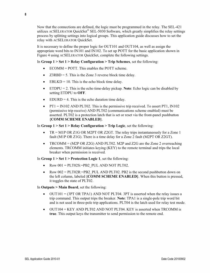
Now that the connections are defined, the logic must be programmed in the relay. The SEL-421 utilizes ACSELERATOR QuickSet® SEL-5030 Software, which greatly simplifies the relay settings process by splitting settings into logical groups. This application guide discusses how to set the relay with ACSELERATOR QuickSet.
It is necessary to define the proper logic for OUT101 and OUT104, as well as assign the appropriate word bits to IN101 and IN102. To set up POTT for the basic application shown in Figure 4 using ACSELERATOR QuickSet, complete the following settings.
In Group 1 > Set 1 > Relay Configuration > Trip Schemes, set the following:
• ECOMM = POTT. This enables the POTT scheme.
• Z3RBD = 5. This is the Zone 3 reverse block time delay.
• EBLKD = 10. This is the echo block time delay.
• ETDPU = 2. This is the echo time-delay pickup. Note: Echo logic can be disabled by setting ETDPU to OFF.
• EDURD = 4. This is the echo duration time delay.
• PT1 = IN102 AND PLT02. This is the permissive trip received. To assert PT1, IN102 (permissive trip receive) AND PLT02 (communications scheme enabled) must be asserted. PLT02 is a protection latch that is set or reset via the front-panel pushbutton {COMM SCHEME ENABLED}.
In Group 1 > Set 1 > Relay Configuration > Trip Logic, set the following:
• TR = M1P OR Z1G OR M2PT OR Z2GT. The relay trips instantaneously for a Zone 1 fault (M1P OR Z1G). There is a time delay for a Zone 2 fault (M2PT OR Z2GT).
• TRCOMM = (M2P OR Z2G) AND PLT02. M2P and Z2G are the Zone 2 overreaching elements. TRCOMM initiates keying (KEY) to the remote terminal and trips the local breaker when permission is received.
In Group 1 > Set 1 > Protection Logic 1, set the following:
• Row 001 = PLT02S:=PB2_PUL AND NOT PLT02.
• Row 002 = PLT02R:=PB2_PUL AND PLT02. PB2 is the second pushbutton down on the left column, labeled {COMM SCHEME ENABLED}. When this button is pressed, it toggles the state of PLT02.
In Outputs > Main Board, set the following:
• OUT101 = (3PT OR TPA1) AND NOT PLT04. 3PT is asserted when the relay issues a trip command. This output trips the breaker. Note: TPA1 is a single-pole trip word bit and is not used in three-pole trip applications. PLT04 is the latch used for relay test mode.
• OUT104 = KEY AND PLT02 AND NOT PLT04. KEY is asserted when TRCOMM is true. This output keys the transmitter to send permission to the remote end.

9
Date Code 20100902 SEL Application Guide 2010-01
Figure 5 shows the basic POTT logic from the settings above.
Figure 5 Basic POTT Logic From Settings Example
MIRRORED BITS Communications Over Fiber MIRRORED BITS communications is a reliable, fast, and easy way to implement a POTT scheme. To use MIRRORED BITS communications, connect fiber to an available serial port on the SEL-421. SEL offers various fiber-to-serial products to fit different types of fiber. Once the fiber is connected to the relay, the port settings must be set to enable MIRRORED BITS communications on each line terminal. Figure 6 shows a typical end-to-end MIRRORED BITS communications connection.
Figure 6 Typical MIRRORED BITS Communications Over Direct Fiber Connection
Alternately, apply MIRRORED BITS communications over a digital network (e.g., multiplexed fiber network) or other communications medium. Refer to SEL Application Guide AG2001-12 [1].
Port Settings Table 5 and Table 6 show example port settings for each end of the line in Figure 6.
Table 5 Port 1 Settings for MIRRORED BITS Communications
Setting Port 1 (Relay at Breaker 3)
Port 1 (Relay at Breaker 4) Comment
PROTO MBA MBA Enable Channel A MIRRORED BITS communications.
MBT N N For a direct fiber application, MBT is set to N. This setting should be set to Y only if a Pulsar 9600 bps
modem is used.
SPEED 38400 38400 Data rate for communications.
STOPBIT 1 1 Defines the number of stop bits used in communications.

10
SEL Application Guide 2010-01 Date Code 20100902
Table 6 Settings in Port 1 > MIRRORED BITS Protocol
Setting Port 1 (Relay at Breaker 3)
Port 1 (Relay at Breaker 4) Comment
TX_ID 2 1 Address number of the remote device that MIRRORED BITS communications is being sent to.
RX_ID 1 2 Address number of the local device receiving MIRRORED BITS communications.
RBADPU 10 10
Channel alarm. Set according to communications channel requirements and to the amount of time the channel must be “bad” before
word bit RBADA asserts.
CBADPU 20000 20000
Channel alarm. Set according to communications channel requirements. When the relay counts CBADPU errors per million transmissions,
the word bit CBADA asserts.
TXMODE N N Set to N for communication between SEL-400 series relays.
MBNUM 4 4
Number of binary MIRRORED BITS communications channels. SEL-400 series relays support advanced
MIRRORED BITS communications, which allows the user to sacrifice some binary channels to gain features
such as transmitting remote analogs and using a virtual terminal. Because a basic POTT scheme only
requires one MIRRORED BIT for the KEY, set MBNUM greater than or equal to 1.
MBTIME N N Allow time synchronization over MIRRORED BITS communications.
MBNUMAN 0 0 Number of MIRRORED BITS designated for analog quantities.
MBNUMVT 3 3
Number of bits designated to a virtual terminal connection. When advanced MIRRORED BITS
communications is used, a virtual terminal connection is available that allows a user to establish a terminal
connection to the remote relay connected via the MIRRORED BITS communications channel. This is helpful for commissioning and can possibly save
travel time between each line terminal. For more information, please see the
SEL-421 Reference Manual.
RMB1FL 0 0
Channel fail state. If the channel is lost, MIRRORED BIT #1 defaults to the deasserted state. This prevents
misoperations for out-of-zone faults when communications are disabled.
RMB1PU 1 1
Number of consecutive messages received to accept the change in bit status. A setting greater than 1 adds more security (at the expense of scheme speed) but is
typically not needed because the local relay supervises tripping via Zone 2 elements.
RMB1DO 1 1 Same as previous except for the received bit dropout.

11
Date Code 20100902 SEL Application Guide 2010-01
Logic Settings The logic settings when using MIRRORED BITS communications are similar to the settings when using hard-wired connections. Replace hard-wired connections IN102 and OUT104 with RMB1A (Receive MIRRORED BIT 1, Channel A) and TMB1A (Transmit MIRRORED BIT 1, Channel A), respectively. Table 7 shows the relationship between hard-wired POTT and MIRRORED BITS communications POTT.
Table 7 Hard-Wired Versus MIRRORED BITS Communications POTT Relay Word Bits
Function Hard-Wired Relay Word Bit MIRRORED BITS Communications Relay Word Bit
Receive permissive trip IN102 RMB1A
Transmit permissive trip OUT104 TMB1A
The following settings must be altered from the hard-wired connection example:
• In Group 1 > Set 1 > Relay Configuration > Trip Schemes, set PT1 = RMB1A AND PLT02.
• In Outputs > MIRRORED BITS Transmit Equations, set TMB1A = KEY AND PLT02 AND NOT PLT04.
To enable open breaker keying with MIRRORED BITS communications over fiber, turn off echo keying, and use the following logic for TMB1A: in Outputs > MIRRORED BITS Transmit Equations, set TMB1A = (KEY or 3PO) AND PLT02 AND NOT PLT04.
The word bit 3PO asserts when the breaker is open and will be received as permission to trip at the remote terminal (RMB1A).
ADVANCED APPLICATIONS The remainder of this application guide covers advanced applications, including:
• Weak-infeed terminals
• Three-terminal lines
• Multiple permissive channels
Weak-Infeed Terminals In some applications, with all sources in, one terminal may not contribute enough fault current to operate the protective elements. A weak terminal is defined as a terminal where the forward-reaching Zone 2 elements cannot detect all in-section, zero-resistance faults. The SEL-421 provides additional logic for weak-infeed terminals to permit rapid tripping of both line terminals for internal faults near the weak terminal. The strong terminal, which can detect all in-section faults, is permitted to trip via a permissive signal echoed back from the weak terminal. The weak terminal can then be programmed to trip if all the following are true:
• Echo key is asserted (EKEY).
• A phase undervoltage or residual overvoltage element is picked up. On a weak terminal, the voltage will drop significantly during fault conditions. These voltage settings are used to supervise the echo-conversion-to-trip (ECTT) element.

12
SEL Application Guide 2010-01 Date Code 20100902
• No reverse-looking elements are picked up.
• All breaker poles are closed.
After these four conditions are met, the weak-infeed logic sets the ECTT word bit. This word bit can be used in the TR equation to trip the weak terminal for a weak-infeed condition.
The following logic includes the additional settings needed for a weak terminal. The strong terminal settings are the same as outlined in the “Applying Basic POTT Logic in the SEL-421” section of this application guide.
In Group 1 > Set 1 > Relay Configuration > Trip Schemes, example settings include:
• EWFC = Y. This enables weak-infeed trip. Set to Y for three-pole trip.
• 27PPW = 80. This is the weak-infeed phase-to-phase undervoltage pickup. Generally set to 70 to 80 percent of the lowest expected system operating voltage.
• 59NW = 5. This is the weak-infeed zero-sequence overvoltage pickup. Generally set to two times the expected standing 3V0 voltage.
In Group 1 > Set 1 > Relay Configuration > Trip Logic, add the ECTT word bit to the TR equation in order to trip the weak terminal: TR = M1P OR Z1G OR M2PT OR Z2GT OR ECTT.
Use the default EBLKD, ETDPU, and EDURD settings as defined in the “Echo Logic” section of this application guide.
Figure 7 is a logic diagram for weak-infeed logic.
PT1
Z3RB
Any Phase Open
27PPW59NW
EWFC:= Y, SP
ETDPU EDURD
WFC
ECTT
00
Figure 7 SEL-421 Weak-Infeed Logic
Three-Terminal Lines In the SEL-321 Phase and Ground Distance Relay, the permissive trip must be assigned to an input or MIRRORED BIT that allows a permissive trip. Also, the permissive trip can only be assigned to one input or one MIRRORED BIT. This leads to additional programming for three-terminal applications. In the SEL-421, PT1 is a setting that can have a logic equation assigned to it. Thus, the logic implementation in the SEL-421 is much easier than in the SEL-321 for three-terminal protection.

13
Date Code 20100902 SEL Application Guide 2010-01
Hard-Wired Connection In a three-terminal application, it is necessary for the local terminal to receive permission from two remote terminals to trip at high speed. This requires that the local terminal Zone 2 setting overreach the other two terminals. Also, the reverse-reaching Zone 3 elements at each terminal must be set to overreach the remote Zone 2 elements under all system conditions.
If hard-wired inputs are used, such as IN102 (Remote Terminal 1 permissive trip receive), IN103 (Remote Terminal 2 permissive trip receive) OUT104 (KEY transmitter to Remote Terminal 1), and OUT105 (KEY transmitter to Remote Terminal 2), only two settings must be changed from the previous hard-wired example:
• In Group 1 > Set 1 > Relay Configuration > Trip Schemes, set PT1= IN102 AND IN103 AND PLT02.
• In Outputs > Main Board, add another output to key the second transmitter: OUT105 = KEY AND PLT02 AND NOT PLT04.
This logic ensures that the local relay only trips at high speed on Zone 2 if it receives permission from each remote end. With two-way communications between each terminal, the relay built-in echo logic, current reversal logic, and weak-infeed logic function properly without the need for additional user-entered logic.
MIRRORED BITS Communications (Option 1) For the best performance in three-terminal lines with MIRRORED BITS communications, use two MIRRORED BITS communications channels. Figure 8 shows bidirectional MIRRORED BITS communications. One important item to note is the communication between Port 2 of RX_ID = 1 and Port 1 of RX_ID = 3. Although the MIRRORED BITS communications channel is defined differently on each side of the communications path, the channel still communicates properly. However, transmitting TMB1A via Port 1 of RX_ID = 3 asserts RMB1B of RX_ID = 1. Conversely, transmitting TMB1B via Port 2 of RX_ID = 1 asserts RMB1A of RX_ID = 3.
Figure 8 Two MIRRORED BITS Communications Channels, Bidirectional POTT Communications
As can be seen from Figure 8, the local terminal can send information directly to each terminal and receive information directly from each terminal. To enable this in the relay, use PROTO=MBB for Port 2; this turns on the second available MIRRORED BITS communications channel. Use the appropriate TX_IDs and RX_IDs, as defined in Figure 8. Also verify that the same data rate is used at all terminals for each channel.

14
SEL Application Guide 2010-01 Date Code 20100902
Use the following logic equations for keying and permission:
• In Group 1 > Set 1 > Relay Configuration > Trip Schemes, set PT1 = RMB1A AND RMB1B AND PLT02.
• In Outputs > MIRRORED BITS Transmit Equations, set:
− TMB1A = KEY AND PLT02 AND NOT PLT04
− TMB1B = KEY AND PLT02 AND NOT PLT04
For a terminal to trip via communications, its Zone 2 elements must be asserted and must receive permission from both remote terminals. When the relay keys permission, it is sent directly to both remote terminals.
With two-way communications between each terminal, the relay built-in echo logic, current reversal logic, and weak-infeed logic function properly without the need for additional user-entered logic.
MIRRORED BITS Communications (Option 2) Figure 9 shows a loop configuration using MIRRORED BITS communications over direct fiber. Notice that communication between relays is only one way and this is accomplished by splitting a pair of fiber. Do not use this option if you have a weak terminal; use Option 1, or consider using a directional comparison blocking (DCB) scheme.
1 3
SEL-421 SEL-421
TXRX
Port 1 (EIA-232) Port 1 (EIA-232)
TX_ID = 2RX_ID = 1
TX_ID = 1RX_ID = 3
Fiber-Optic Transceiver
SEL-421
2
Port 1 (EIA-232)
TX_ID = 3RX_ID = 2
RXTX
TXRX
Fiber-Optic Transceiver
Fiber-Optic Transceiver
Figure 9 Three-Terminal MIRRORED BITS Communications Over Direct Fiber Application

15
Date Code 20100902 SEL Application Guide 2010-01
To apply this scheme, Port 1 of each relay must be set with the corresponding TX_ID and RX_ID shown in Figure 9. Use the following logic settings for keying and permission (with breaker open keying added):
• In Group 1 > Set 1 > Relay Configuration > Trip Schemes, set PT1 = RMB1A AND RMB2A.
• In Outputs > MIRRORED BITS Transmit Equations, set:
− TMB1A = (KEY OR 3PO) AND PLT02 AND NOT PLT04
− TMB2A = RMB1A AND PLT02 AND NOT PLT04
• In Group 1 > Set 1 > Relay Configuration > Trip Schemes, set ETDPU = OFF.
These settings allow a terminal to trip if the other two terminals have sent permission. Because communication in this scheme is only in one direction, it is necessary for one MIRRORED BIT to pass through a terminal on its way to the next terminal. In this scheme, RMB1A assertion means the first downstream communications device has sent permission. If RMB2A has asserted, the second downstream communications device sent permission via TMB1A and then was rerouted to TMB2A in the first downstream communications device.
It is important to realize that the speed of the one-way POTT scheme is slower than a two-way communications scheme. This is due to the latency introduced by passing MIRRORED BITS communications through an additional terminal. For an SEL-421 operating at 19200 bps in this communications scheme, the added delay for clearing an in-section fault is approximately 0.4 cycles. If the communications speed is 9600 bps, the delay is 0.75 cycles. These delays are based on the published one-way communications delay for SEL devices using MIRRORED BITS communications. See SEL Application Guide AG2001-12 for more information [1].
Another side effect of using this communications scheme is that the relay built-in echo logic can no longer be used to provide fast and secure tripping. If Breaker 2 is open and a fault is close in to Breaker 3, it could take 3.6 cycles1(total echo time2) from the fault inception for echoed permission from Breaker 2 to reach Breaker 1 at 19200 bps with the default echo settings. By that time, the permission sent from Breaker 3 to Breaker 1 may have dropped out, because Breaker 3 will likely be open within 3 cycles. This leads to Breaker 1 never receiving both permissions at the same time and consequently tripping on a time-delayed backup element.
Because the echo logic cannot be used, the relay is set to key for a three-pole open (3PO) condition to allow for fast clearance of faults when any breaker is open on the three-terminal line.
1 3.6 cycles = (0.4~ delay from B3 to B1 + 0.4~ delay from B1 to B2) + (2~ delay for ETDPU) + (0.4~ delay from B2 to B3 + 0.4~ delay from B3 to B1) 2 Total echo time = (total time to receive both permissions) + (echo PU timer) + (time to transmit both permissions)
16
SEL Application Guide 2010-01 Date Code 20100902
Multiple Permissive Channels For the following examples, single-pole tripping must be enabled in the relay. To enable single-pole tripping in the relay, please consult the SEL-421 Reference Manual.
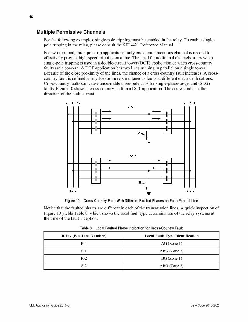
For two-terminal, three-pole trip applications, only one communications channel is needed to effectively provide high-speed tripping on a line. The need for additional channels arises when single-pole tripping is used in a double-circuit tower (DCT) application or when cross-country faults are a concern. A DCT application has two lines running in parallel on a single tower. Because of the close proximity of the lines, the chance of a cross-country fault increases. A cross-country fault is defined as any two or more simultaneous faults at different electrical locations. Cross-country faults can cause undesirable three-pole trips for single-phase-to-ground (SLG) faults. Figure 10 shows a cross-country fault in a DCT application. The arrows indicate the direction of the fault current.
Figure 10 Cross-Country Fault With Different Faulted Phases on Each Parallel Line
Notice that the faulted phases are different in each of the transmission lines. A quick inspection of Figure 10 yields Table 8, which shows the local fault type determination of the relay systems at the time of the fault inception.
Table 8 Local Faulted Phase Indication for Cross-Country Fault
Relay (Bus-Line Number) Local Fault Type Identification
R-1 AG (Zone 1)
S-1 ABG (Zone 2)
R-2 BG (Zone 1)
S-2 ABG (Zone 2)

17
Date Code 20100902 SEL Application Guide 2010-01
Table 8 indicates there is a problem in the fault type identification of this cross-country fault. Ideally, the local faulted phase selection should agree between the two terminals of the transmission line relaying scheme. With only one communications channel, the relays at Bus S both trip all three phases (undesirably) upon a received permission because the relay sees a multiphase fault.
Upon detection of this fault, the relays at Bus R trip instantaneously via Zone 1 and open their associated breakers. This effectively isolates the breakers at Bus S from seeing the multiphase fault. Bus S relays now only see the phase-to-ground fault that is in front of them and correctly identify an SLG fault. So if the relays at Bus S wait until after the breakers at Bus R operate to make a tripping decision, an undesirable three-pole trip can be avoided.
To allow for correct single-pole tripping in a DCT application, a second communications channel must be added. The two channels have the following functions:
• KEY1 is the transmit single-pole (general) permissive trip.
• KEY3 is the transmit three-pole permissive trip.
For a three-pole trip to occur, the receipt of both KEY1 and KEY3 is required. This allows the relay to determine if there is agreement at both line ends on the fault type declaration. For example, if the local relay receives KEY1 and identifies the fault as SLG, the local relay issues a trip to the phase identified by the relay fault indication logic. However, if the local relay identifies the fault as being multiphase yet does not receive KEY3, it suspends tripping until one of the following events occurs:
• The relay receives a KEY3.
• The local relay fault indication changes to SLG.
For the example in Figure 10, the relays at Bus R trip and send KEY1 to the relays at Bus S. However, until the breakers at Bus R open, the relays at Bus S declare a multiphase fault. Because Bus S relays received KEY1 but not KEY3, the relays at Bus S are not permitted to trip. Once the breakers at Bus R open, Bus S correctly identifies the fault and trips a single phase only.
Two-Channel Logic Note: In these examples, Phase A 52A = IN101, Phase B 52A = IN102, Phase C 52A = IN103, Receiver 1 = IN104, and Receiver 2 = IN105.
To enable a two-channel permissive scheme using PLC or audio tone equipment, use the following POTT logic (if MIRRORED BITS communications is available, use the three-channel method described in the next section):
• In Group 1 > Set 1 > Relay Configuration > Trip Schemes, set:
− ECOMM = POTT2
− PT1 = IN104 AND PLT02
− PT3 = IN105 AND PLT02
• In Outputs > Main Board, set:
− OUT104 = KEY1 OR EKEY AND IN104
− OUT105 = KEY3 OR EKEY AND IN105
Using the logic (EKEY AND IN104) allows the user to echo back the appropriate permissive signal if an open breaker or a weak-infeed condition exists.
18
SEL Application Guide 2010-01 Date Code 20100902
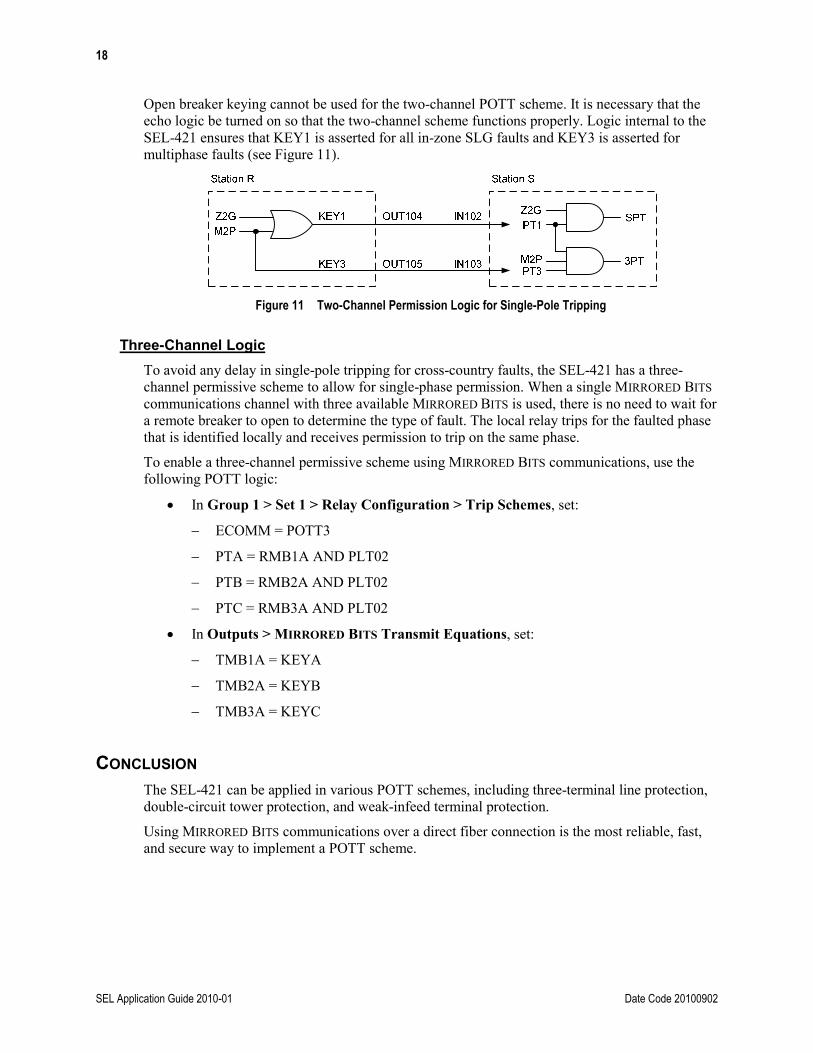
Open breaker keying cannot be used for the two-channel POTT scheme. It is necessary that the echo logic be turned on so that the two-channel scheme functions properly. Logic internal to the SEL-421 ensures that KEY1 is asserted for all in-zone SLG faults and KEY3 is asserted for multiphase faults (see Figure 11).
Figure 11 Two-Channel Permission Logic for Single-Pole Tripping
Three-Channel Logic To avoid any delay in single-pole tripping for cross-country faults, the SEL-421 has a three-channel permissive scheme to allow for single-phase permission. When a single MIRRORED BITS communications channel with three available MIRRORED BITS is used, there is no need to wait for a remote breaker to open to determine the type of fault. The local relay trips for the faulted phase that is identified locally and receives permission to trip on the same phase.
To enable a three-channel permissive scheme using MIRRORED BITS communications, use the following POTT logic:
• In Group 1 > Set 1 > Relay Configuration > Trip Schemes, set:
− ECOMM = POTT3
− PTA = RMB1A AND PLT02
− PTB = RMB2A AND PLT02
− PTC = RMB3A AND PLT02
• In Outputs > MIRRORED BITS Transmit Equations, set:
− TMB1A = KEYA
− TMB2A = KEYB
− TMB3A = KEYC
CONCLUSION The SEL-421 can be applied in various POTT schemes, including three-terminal line protection, double-circuit tower protection, and weak-infeed terminal protection.
Using MIRRORED BITS communications over a direct fiber connection is the most reliable, fast, and secure way to implement a POTT scheme.

19
Date Code 20100902 SEL Application Guide 2010-01
APPENDIX A: CURRENT REVERSALS In double-circuit line applications, faults near one end of the line may result in a sequential trip operation. This sequential trip happens when the instantaneous relay elements trip the breaker nearest to the fault location (this trip is independent from the communications tripping scheme). The breaker furthest from the fault must wait for a permissive signal. The major problem with this sequential fault current clearance is that it creates a current reversal in the healthy parallel line. If the protection for the healthy line is not equipped to address this reversal, one terminal of the healthy (nonfaulted) line may trip incorrectly.
Figure 12 shows a double-circuit line configuration at the inception of the fault; Figure 13 shows the configuration after Breaker 3 opens.
Figure 12 Fault Inception With All Sources In
Figure 13 Faulted System With Breaker 3 Open
In Figure 12, relaying at Breaker 3 detects the fault as being within Zones 1 and 2. The instantaneous Zone 1 element issues a trip signal to the breaker independent of the communications-assisted tripping scheme. The Zone 2 elements at Breaker 3 issue a permissive signal to the protection at Breaker 4. The protection at Breaker 4 detects the fault within Zone 2 but must wait for the permissive signal from Breaker 3 before issuing a permissive trip output. In the event that the permissive trip signal never arrives and the fault persists, Breaker 4 is tripped by Zone 2 time-delayed protection.
The Zone 2 element at Breaker 2 also picks up at fault inception and issues a permissive signal to the protection scheme at Breaker 1. At this time, the Zone 3 elements at Breaker 1 also pick up and identify the fault as being reverse (or out of section) to its location.
After Breaker 3 opens (see Figure 13), the fault currents redistribute. When this redistribution occurs, the Zone 2 element at Breaker 2 and the Zone 3 element at Breaker 1 begin to drop out. If the Zone 2 element at Breaker 1 picks up before the received permissive signal resets, Breaker 1 trips because of this current reversal.
20
SEL Application Guide 2010-01 Date Code 20100902
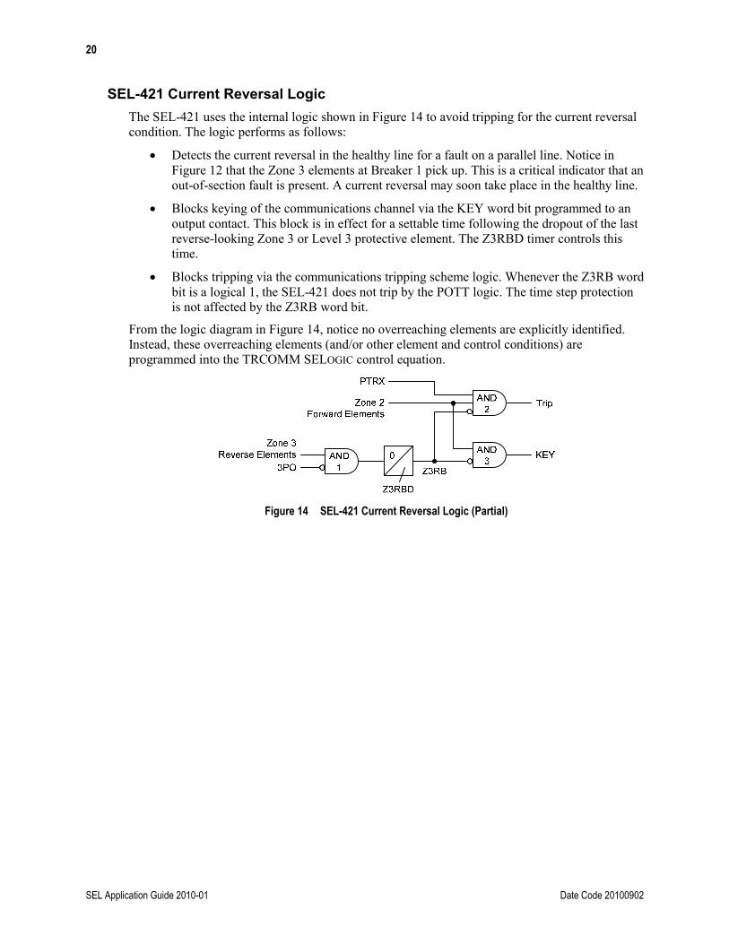
SEL-421 Current Reversal Logic The SEL-421 uses the internal logic shown in Figure 14 to avoid tripping for the current reversal condition. The logic performs as follows:
• Detects the current reversal in the healthy line for a fault on a parallel line. Notice in Figure 12 that the Zone 3 elements at Breaker 1 pick up. This is a critical indicator that an out-of-section fault is present. A current reversal may soon take place in the healthy line.
• Blocks keying of the communications channel via the KEY word bit programmed to an output contact. This block is in effect for a settable time following the dropout of the last reverse-looking Zone 3 or Level 3 protective element. The Z3RBD timer controls this time.
• Blocks tripping via the communications tripping scheme logic. Whenever the Z3RB word bit is a logical 1, the SEL-421 does not trip by the POTT logic. The time step protection is not affected by the Z3RB word bit.
From the logic diagram in Figure 14, notice no overreaching elements are explicitly identified. Instead, these overreaching elements (and/or other element and control conditions) are programmed into the TRCOMM SELOGIC control equation.
Figure 14 SEL-421 Current Reversal Logic (Partial)

21
Date Code 20100902 SEL Application Guide 2010-01
Table 9 and the timing sequence in Figure 15 outline the logic process, which safeguards Breaker 1 against a misoperation during the current reversal condition described above.
Table 9 Logic Process
Time Reference Logic Performed
Fault inception
At Breaker 1
Zone 3 element picks up.
Breaker is in the closed state.
Reverse block timer initiated to block permissive logic; Z3RB is a logical 1.
Permissive signal is received from Breaker 2. In actual practice, the Zone 3 element at Breaker 1 should assert
before the Zone 2 elements at Breaker 2 pick up. Communications channel time is assumed to be near
zero for this example.
At Breaker 2 Zone 2 element picks up.
Breaker is in the closed state.
Breaker 3 opens
At Breaker 1
Zone 3 element drops out.
Zone 2 element picks up.
Permissive signal is still present from Breaker 2.
Reverse block timer begins timing to drop out; Z3RB is still in logical 1.
Z3RB blocks sending a permissive signal to Breaker 2.
At Breaker 2
Zone 2 element drops out.
Zone 3 element picks up.
Breaker is in the closed state.
Reverse block timer initiated to block permissive logic; Z3RB is a logical 1.
Breaker 4 opens
At Breaker 1 Zone 2 element drops out.
At Breaker 2 Zone 3 element drops out.
Reverse block timer starts to time out.

22
SEL Application Guide 2010-01 Date Code 20100902
As the timing sequence in Figure 15 shows, the key factors in the current reversal logic are the pickup of the reverse-looking Zone 3/Level 3 elements and the time-delayed dropout of the Zone 3 reverse block timer (Z3RBD).
1
4
2
Zone 2 Zone 3
3
1
4
2
Zone 1 Zone 2
Zone 3 Zone 2
Breaker 1
Breaker 2
Zone 3
Zone 2
52a
Z3RB
PT RX
0
0
1
1
1
01
01
0
0
1
1
0
0
1
1
Zone 3
Zone 2
52a
Z3RB
PT RX
Z3RBD Timing
Z3RBD Timing
Breaker 3 OpensFault Inception Breaker 4
Opens Figure 15 Current Reversal Timing Sequence
Z3RBD Setting Considerations Factors that influence the Z3RBD timer setting include:
• Remote terminal Zone 2 reset time
• Channel reset time
To be conservative, you should add some margin to the summation of the times listed above. A safe margin (and known quantity) is the maximum expected operating time of a breaker on the parallel faulted line.
23
Date Code 20100902 SEL Application Guide 2010-01
For instance, assume the following for the circuit shown in Figure 12:
• Remote terminal Zone 2 reset time is 1 cycle.
• Channel reset time is 1 cycle.
• Parallel line breaker operate time is 3 cycles.
A fault near one terminal on the parallel line would be totally cleared in 5 cycles (4 cycles at the near end, 5 cycles at the remote end). The Z3RBD timer must be set so that after the current reverses in the healthy line, the near terminal neither issues a permissive signal nor allows a permissive signal-assisted trip. Given that the Z3RBD timer does not begin to decrement until the Zone 3 elements drop out, a conservative Z3RBD setting is the sum of remote terminal Zone 2 reset time, channel reset time, and breaker operate time (in this example, Z3RBD = 5 cycles).
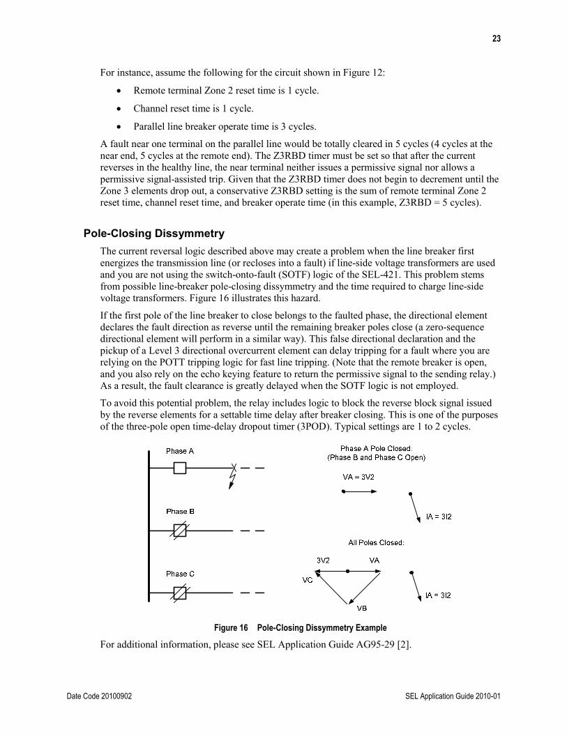
Pole-Closing Dissymmetry The current reversal logic described above may create a problem when the line breaker first energizes the transmission line (or recloses into a fault) if line-side voltage transformers are used and you are not using the switch-onto-fault (SOTF) logic of the SEL-421. This problem stems from possible line-breaker pole-closing dissymmetry and the time required to charge line-side voltage transformers. Figure 16 illustrates this hazard.
If the first pole of the line breaker to close belongs to the faulted phase, the directional element declares the fault direction as reverse until the remaining breaker poles close (a zero-sequence directional element will perform in a similar way). This false directional declaration and the pickup of a Level 3 directional overcurrent element can delay tripping for a fault where you are relying on the POTT tripping logic for fast line tripping. (Note that the remote breaker is open, and you also rely on the echo keying feature to return the permissive signal to the sending relay.) As a result, the fault clearance is greatly delayed when the SOTF logic is not employed.
To avoid this potential problem, the relay includes logic to block the reverse block signal issued by the reverse elements for a settable time delay after breaker closing. This is one of the purposes of the three-pole open time-delay dropout timer (3POD). Typical settings are 1 to 2 cycles.
Figure 16 Pole-Closing Dissymmetry Example
For additional information, please see SEL Application Guide AG95-29 [2].

24
SEL Application Guide 2010-01 Date Code 20100902
APPENDIX B: SENSITIVITY COORDINATION WITH OTHER RELAY TYPES You should be aware of relay sensitivities when coordinating the SEL-421 with other types of relays in a POTT scheme. Specifically, the relay elements and/or sensitivities may be dissimilar enough to present a coordination difficulty for external faults. For example, consider the system shown in Figure 17.
Figure 17 Example System Single-Line Diagram Showing Sensitivity Miscoordination
If a fault occurs on the line between Breakers 5 and 6, Breaker 3 sends a permissive trip signal to the relaying at Breaker 4 (assuming that the relaying at Breaker 3 is sensitive enough to sense this fault). If the protection at Breaker 4 is so insensitive as to not sense this reverse fault and this Breaker 4 protection is using echo logic similar to that described earlier, Breaker 4 echoes the received permissive trip signal. The result is that Breaker 3 trips for an out-of-section fault. This misoperation can be avoided with more sensitive protective elements at Breaker 4.
This miscoordination can be caused by the following:
• Reverse-looking protective elements not sensitive enough. Some relays, including the SEL-221H and SEL-221G, include ground directional elements (67N1 through 67N3) but do not have ground distance elements. As source impedances and fault resistance magnitudes change, the fault resistance coverage of these directional elements changes.
Source changes can also have an appreciable effect on the fault resistance coverage capability of ground distance elements.
It is very important to use reverse-looking elements that can sense any fault detected by the forward-looking elements at the remote terminal.
• Directional element sensitivity mismatches. Different relays have dissimilar polarizing and operating quantities and different minimum sensitivity thresholds.
For a reliable POTT scheme, the relays at each line terminal should have similar sensitivities. If the sensitivities are not matched, a misoperation or failure to operate could occur. When coordinating the SEL-421 with other relay types, you should consult your fault study to ensure that each relay has adequate operating quantities for all internal and external faults.
For a more detailed discussion of ground relaying sensitivities, please refer to the technical paper “Limits to the Sensitivity of Ground Directional and Distance Protection” [3]. This paper identifies limits to relaying sensitivities and how much fault resistance is covered for various fixed and settable directional element limits. It also provides some useful tools for verifying relay settings in practice.

25
Date Code 20100902 SEL Application Guide 2010-01
In summary, when applying the SEL-421 with other types of relays, note the following:
• If possible, match the directional and protective element sensitivities at both line ends. Use the same protective elements at each line end whenever possible, and set reverse-reaching elements more sensitive than the remote overreaching elements.
• Verify that the directional elements and pickup settings at each line terminal have sufficient operating quantities to detect both internal and external faults.
• If you cannot follow the steps outlined above, consider disabling the echo keying logic at the less sensitive terminal. Doing this will avoid a misoperation when the less sensitive terminal does not pick up a reverse-looking element for an out-of-section fault while the remote relaying does pick up.
For additional information, please see SEL Application Guide AG95-29 [2].
REFERENCES [1] K. Behrendt and K. Fodero, “Implementing MIRRORED BITS Technology Over Various
Communications Media,” SEL Application Guide (AG2001-12), July 2007. Available: http://www.selinc.com.
[2] A. Guzmán, J. Roberts, and K. Zimmerman, “Applying the SEL-321 Relay to Permissive Overreaching Transfer Trip (POTT) Schemes,” SEL Application Guide (AG95-29), August 2005. Available: http://www.selinc.com.
[3] J. Roberts, E. O. Schweitzer, III, R. Arora, and E. Poggi, “Limits to the Sensitivity of Ground Directional and Distance Protection,” proceedings of the 1997 Spring Meeting of the Pennsylvania Electric Association Relay Committee, Allentown, PA, May 1997. Available: http://www.selinc.com.
FACTORY ASSISTANCE We appreciate your interest in SEL products and services. If you have questions or comments, please contact us at:
Schweitzer Engineering Laboratories, Inc. 2350 NE Hopkins Court Pullman, WA 99163-5603 USA Telephone: +1.509.332.1890 Fax: +1.509.332.7990 www.selinc.com • [email protected]

26
SEL Application Guide 2010-01 Date Code 20100902
© 2010 by Schweitzer Engineering Laboratories, Inc. All rights reserved.
All brand or product names appearing in this document are the trademark or registered trademark of their respective holders. No SEL trademarks may be used without written permission.
SEL products appearing in this document may be covered by U.S. and Foreign patents.
*AG2010-01*