ag & turf division -...
TRANSCRIPT

JOHN DEEREAG & TURF DIVISION
M165241
K1
SpreaderLP39087
OMM165241 K1
OPERATOR’S MANUAL
Original InstructionAll information, illustrations and
specifications in this manual are based on the latest information at the time of
publication. The right is reserved to make changes at any time without notice.
COPYRIGHT© 2012Deere & Co.
John Deere Ag & Turf DivisionAll rights reservedPrevious Editions
COPYRIGHT©
North American VersionLitho in U.S.A.

Introduc
Introduction
Table of ContentsIntroduction................................................................................................ 1
Product Identification................................................................................. 1
Safety ........................................................................................................ 2
Assembly................................................................................................... 3
Installing .................................................................................................... 9
Removing and Storing............................................................................... 9
Operating................................................................................................... 9
Service .................................................................................................... 11
Specifications .......................................................................................... 12
Getting Quality Service ........................................................................... 12
IntroductionUsing Your Operator’s ManualRead this entire operator’s manual, especially the safety information, before operating.
This manual is an important part of your machine. Keep all manuals in a convenient location so they can be accessed easily.
Use the safety and operating information in this manual to operate the machine safely and correctly. Use the service information to make any needed adjustments and routine service to your machine.
If you have any questions or concerns with the assembly, installation, or operation of this machine, see your local John Deere dealer or call John Deere Special Services at 1-800-448-9282 for assistance.
Product IdentificationProduct CompatibilityThis spreader is designed for use with lawn tractors and lawn and garden tractors.
Record Purchase InformationRecord your purchase information in the spaces provided below.
DATE OF PURCHASE:
_________________________________________
DEALER NAME:
_________________________________________
DEALER PHONE:
_________________________________________
tion - 1

Safety
SafetyRead Safety in Machine Operator’s ManualRead the general safety operating precautions in your machine operator’s manual for additional safety information.
Operating Safely
• Read the machine and attachment operator’s manual carefully. Be thoroughly familiar with the controls and the proper use of the equipment. Know how to stop the machine and disengage the controls quickly.
• This attachment is intended for use in lawn care and home applications. Do not use for use other than intended by the manufacturer.
• Do not modify machine or safety devices. Unauthorized modifications to the machine or attachment may impair its function and safety.
• Do not let children or an untrained person operate machine.
• Make any necessary adjustments before you operate. Never attempt to make any adjustments while the engine is running, unless if recommended in adjustment procedure.
• Look behind machine before you back up. Back up carefully.
• Do not let anyone, especially children, ride on machine or attachment. Riders are subject to injury such as being struck by foreign objects and being thrown off. Riders may also obstruct the operator’s view, resulting in the machine being operated in an unsafe manner.
• Disengage any power to the attachment when the machine is transported or not in use.
Practice Safe Maintenance
• Only qualified, trained adults should service this machine.
• Understand service procedure before doing work. Keep area clean and dry.
• Do not operate the engine in a confined space where dangerous carbon monoxide fumes can collect.
• Never lubricate, service or adjust the machine or attachment while it is moving. Keep safety devices in place and in working condition. Keep hardware tight.
• Keep hands, feet, clothing, jewelry, and long hair away from any moving parts, to prevent them from getting caught.
• Disconnect battery or remove spark plug wire (for gasoline engines) before making any repairs.
• Keep all parts in good condition and properly installed. Fix damage immediately. Replace worn or broken parts. Replace all worn or damaged safety and instruction decals.
• Check all hardware at frequent intervals to be sure the equipment is in safe working condition.
• Do not modify machine or safety devices. Unauthorized modifications to the machine or attachment may impair its function and safety.
Wear Appropriate Clothing
• Always wear eye protection when operating the machine.
• Wear close fitting clothing and safety equipment appropriate for the job.
• While operating this machine, always wear substantial footwear and long trousers. Do not operate the equipment when barefoot or wearing open sandals.
• Wear a suitable protective device such as earplugs. Loud noise can cause impairment or loss of hearing.
Keep Riders Off Towed Attachment
• Keep riders off of a towed attachment.
• Riders on a towed attachment are subject to injury, such as being struck by objects and being thrown off the attachment during sudden starts, stops and turns.
• Riders obstruct the operator's view, resulting in the attachment being used in an unsafe manner.
• Keep riders off of hitch bracket.
Protect Bystanders
• Keep bystanders away when you operate a towed attachment.
• Before you back machine and attachment, look carefully behind attachment for bystanders.
Safety - 2

Assembly
AssemblyParts in Kit
Main Assembly Parts
MX50363
A B
C
DE
F G
H
I
J
K
L
M
N
Qty. Description
1 Hopper (A)
1 Left Hitch Support Tube (B)
1 Right Hitch Support Tube (C)
1 Hitch Bracket (D)
1 Hitch Tube (E)
1 Flow Control Rod (F)
2 Hopper Brace (G)
1 Cross Brace (H)
1 Impeller (I)
1 Gearbox (with Axle) (J)
1 Flow Control Assembly (K)
1 Right Hopper Support Tube (L)
1 Left Hopper Support Tube (M)
2 Wheel (N)
Qty. Description
Assembly - 3

Assembly
Bag of PartsMX50364
Picture Note: Parts shown full size except in box.
mm
O P Q R S T U V
W
X
Y
Z
aa
bb
ccdd
ee
ff
gghh
llkkjj
oo nn
pp
ii
Qty. Description
1 Hitch Pin, 3/8 x 2-7/8 in. (O)
2 Bolt, 1/4 x 2-1/2 in. (P)
2 Bolt, 1/4 x 2 in. (Q)
6 Bolt, 1/4 x 1-3/4 in. (R)
2 Bolt, 1/4 x 1-1/2 in. (S)
1 Bolt, 1/4 x 1 in. (T)
2 Bolt, 5/16 x 1-1/4 in. (U)
1 Carriage Bolt, 1/4 x 3/4 in. (V)
2 Locknut, 5/16 in. (W)
13 Locknut, 1/4 in. (X)
1 Cotter Pin, 3/32 x 3/4 in. (Y)
1 Cotter Pin, 1/8 x 1-1/2 in. (Z)
1 Cotter Pin, 3/16 x 2 in. (aa)
1 Hairpin, Agitator (bb)
1 Hairpin Cotter (cc)
4 Washer, Large (dd)
5 Washer, Nylon (ee)
9 Washer, Small (ff)
2 Spacer, Axle (gg)
Qty. Description
Assembly - 4
Assembly
Tools Required for Assembly
• (1) Hammer
• (1) Pliers
• (2) 7/16” Wrench
• (2) 1/2” Wrench
Assemble Frame Tubes
MX50369
1. Insert a tube plug (ll) into the ends of the hitch tube (E).
2. Attach the hitch bracket (D) to the hitch tube using two 5/16 x 1-1/4 in. hex bolts (U) and 5/16 in. locknuts (W). Tighten hardware.
3. Install the 3/8 x 2-7/8 in. hitch pin (O) in the hitch bracket and hitch tube and secure it with the hairpin cotter (cc).
MX50370
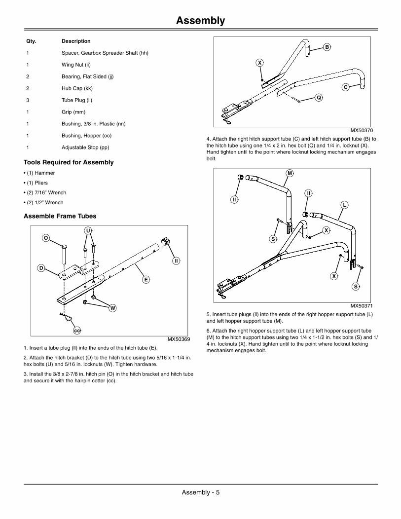
4. Attach the right hitch support tube (C) and left hitch support tube (B) to the hitch tube using one 1/4 x 2 in. hex bolt (Q) and 1/4 in. locknut (X). Hand tighten until to the point where locknut locking mechanism engages bolt.
MX50371
5. Insert tube plugs (ll) into the ends of the right hopper support tube (L) and left hopper support tube (M).
6. Attach the right hopper support tube (L) and left hopper support tube (M) to the hitch support tubes using two 1/4 x 1-1/2 in. hex bolts (S) and 1/4 in. locknuts (X). Hand tighten until to the point where locknut locking mechanism engages bolt.
1 Spacer, Gearbox Spreader Shaft (hh)
1 Wing Nut (ii)
2 Bearing, Flat Sided (jj)
2 Hub Cap (kk)
3 Tube Plug (ll)
1 Grip (mm)
1 Bushing, 3/8 in. Plastic (nn)
1 Bushing, Hopper (oo)
1 Adjustable Stop (pp)
Qty. Description
ll
E
cc
W
D
OU
Q
X
B
C
S
llll
M
L
S
X
X
Assembly - 5

Assembly
MX50372
7. Insert the 3/8 in. plastic bushing (nn) into the cross brace (H).
8. Attach the cross brace to the hopper support tubes using two 1/4 x 2-1/2 in. hex bolts (P) and 1/4 in. locknuts (X). Hand tighten until to the point where locknut locking mechanism engages bolt.
Install Gearbox and Hopper
NOTE: Be certain hole (qq) is installed on the side shown.
MX50373
1. Install the gearbox (J) by inserting the spreader shaft vertically into the bushing in the cross brace (H) and inserting the axle into the ends of the right hopper support tube (L) and left hopper support tube (M).
MX50374
2. Slide the flat sided bearings (jj) onto the axle and insert them into the ends of the hopper support tubes.
3. Slide the spreader impeller (I) onto the spreader shaft and secure it with a 1/8 x 1-1/2 in. cotter pin (Z), spreading the ends of the pin around the shaft.
MX50375
4. Place the hopper (A) on the hopper support tubes, inserting the spreader shaft up through the square hole in the bottom of the hopper.
5. Slide the hopper bushing (oo) onto the spreader shaft and insert it into bottom of the hopper.
6. Slide the gearbox spreader shaft spacer (hh) onto the spreader shaft.
7. Install the agitator hairpin (bb) in the spreader shaft.
P
X
nn
P
X
H
L
J
M
H
jj
Z
I
jj
bb
A
oo
hh
Assembly - 6

Assembly
MX50376
8. Attach the hopper (A) to the hopper support tubes using four 1/4 x 1-3/4 in. hex bolts (R), small washers (ff), nylon washers (ee) and 1/4 in. locknuts (X) installed finger tight.
9. Insert the 1/4 x 1 in. hex bolt (T) into the hole in the bottom of the hopper, pressing the head of the bolt into the hex shaped recess of the hole. Install a 1/4 in. locknut (X) onto the bolt and tighten completely.
Install Flow Control
MX50377
1. Install the grip (mm) onto the flow control assembly (K) lever.
2. Assemble the adjustable stop (pp) to the flow control bracket (ss) using
the 1/4 x 3/4 in. carriage bolt (V), nylon washer (ee) and wing nut (ii).
MX50378
3. Attach the flow control bracket to the hitch tube (E) using two 1/4 x 1-3/4 in. hex bolts (R), four small washers (ff) and two 1/4 in. locknuts (X). Hand tighten until to the point where locknut locking mechanism engages bolt.
MX50379
4. Install the flow control rod (F), inserting the end without a hole into the elongated hole in the flow plate on the bottom of the hopper. Lock the rod in the flow plate by rotating it to a forward facing position.
T
R
ff
ee
AX
X
ee
V
K
ii
mm
pp
ss
ff
X
ffR
E
F
Assembly - 7

Assembly
MX50380
5. Swing the end of the flow control rod (F) into the flow control assembly lever, and secure it with a small washer (ff) and a 3/32 x 3/4 in. cotter pin (Y), spreading the ends of the pin around the rod.
MX50381
6. Install the hopper braces (G) to the upper hopper support tube bolts installed earlier using two 1/4 in. locknuts (X). Hand tighten until to the point where locknut locking mechanism engages bolt.
7. Fasten the loose ends of the hopper braces (G) to the hitch tube using a 1/4 x 2 in. hex bolt (Q) and a 1/4 in. locknut (X).
8. With the exception of two locknuts securing the flow control bracket to the hitch tube, tighten all remaining hardware on the spreader completely.
Install Wheels
MX50382
1. Slide a large washer (dd), an axle spacer (gg), a large washer (dd) and a wheel (N) onto the left side of the axle.
2. Install a hub cap (kk) onto the axle, and gently tap hub cap securely onto axle with a hammer.
MX50383
3. Slide a large washer (dd), a spacer (gg), a large washer (dd) and a wheel (N) onto the right side of the axle.
4. Attach the wheel to the axle with a 3/16 x 2 in. cotter pin (aa), spreading the ends of the pin around the shaft.
5. Install a hub cap (kk) onto the axle, and gently tap hub cap securely onto axle with a hammer.
Y
F
ff
Q
X
G
X
dd
gg
N
kk
dd
dd
aa
kk
gg
dd
N
Assembly - 8

Installing
Adjust Flow Control
MX50384
Picture Note: Flow control assembly lever shown in position 5.
1. Set the adjustable stop (pp) at “5” and move the flow control assembly (K) lever back against it.
NOTE: The higher the setting number, the wider the flow plate in the bottom of the hopper will open. The flow plate should open about half way with the adjustable stop set at “5”.
2. Slide the flow control assembly (K) bracket forward or back until the flow plate in the bottom of the hopper is open half way.
3. Tighten the 1/4 in. locknuts (X) on two bolts fastening the flow control bracket. Do not deform the control bracket.
4. Make sure the flow plate will open and close all the way. Adjust again, if necessary.
InstallingInstalling the Spreader
1. Park machine safely. (See Parking Safely in the Safety Section in the machine operator’s manual.)
2. Align spreader hitch tube with machine drawbar.
3. Install hitch pin through spreader hitch bracket and tube and machine drawbar.
4. Install hair cotter pin in hitch pin.
Removing and StoringRemoving
1. Park machine safely. (See Parking Safely in the Safety Section in the machine operator’s manual.)
2. Remove all materials from the hopper before removing spreader from machine.
3. Remove hair cotter pin and hitch pin from machine drawbar and spreader hitch bracket and tube.
Storing
1. Rinse inside of hopper and exterior of spreader. Allow to dry before storing.
2. Store in a clean, dry area.
OperatingDaily Operating Checklist
❏ Check for loose or missing hardware.
❏ Make sure all connections are tight.
❏ Make sure attachment responds properly to controls.
❏ Check for debris build-up that could obstruct proper motion of the spreader control components.
Material Application Chart
NOTE: Material application rates shown in chart are affected by humidity and moisture content of the material (granular and pellet). Some minor setting adjustment may be necessary to compensate for this condition.
pp
K
X
c CAUTION: Avoid injury! Keep hands, feet and other body parts away from under drawbar.
MATERIAL TYPE FLOW SETTING SPREAD WIDTH
FERTILIZER
Powder 3 - 5 3 - 4 ft.
Granular 3 - 5 8 - 10 ft.
Pelleted 3 - 5 10 - 12 ft.
Organic 6 - 8 6 - 8 ft.
GRASS SEED
Fine 3 - 4 6 - 7 ft.
Coarse 4 - 5 8 - 9 ft.
ICE MELTER 6 - 8 10 - 12 ft.
Installing - 9

Operating
Setting Flow Control
NOTE: Refer to the Material Application Chart and instructions on the fertilizer bag to select the proper flow rate setting.
MX50384
Picture Note: Flow control assembly lever shown in position 5.
1. Loosen the nylon wing nut (ii), set the adjustable stop (pp) to the desired flow rate setting and tighten the wing nut.
NOTE: The higher the setting number, the wider the flow plate in the bottom of the hopper will open. The flow plate should open about half way with the adjustable stop set at “5”. If it does not, see “Adjust Flow Control” in the ASSEMBLY Section.
2. Refer to the application chart on this page and to the instructions on the fertilizer bag to select the proper flow rate setting.
3. Pull the flow control assembly (K) lever against the adjustable stop for the on position and toward the hopper for the off position.
Operating the Spreader
NOTE: We do not recommend the use of any powdered lawn chemicals, due to difficulty in obtaining a satisfactory or consistent broadcast pattern.
1. Determine approximate square footage of area to be covered and estimate amount of material required.
2. Make sure the flow plate is closed.
3. Fill the hopper, breaking up any lumpy fertilizer.
4. Set the flow control dial with the flow plate closed. Refer to the instructions on the fertilizer bag and to the application chart above to select the proper flow rate setting. The application chart is calculated for light to heavy application at a vehicle speed of 3 mph, or 100 ft in 23 seconds. A variation in speed will require an adjustment of the flow rate to maintain the same coverage. The faster you drive, the wider the broadcast width. Do not exceed 6 mph.
5. Always start the tractor in motion before opening the flow plate.
6. Always close the flow plate before turning or stopping the tractor.
7. If fertilizer is accidentally deposited too heavily in a small area, soak the area thoroughly with a garden hose or sprinkler to prevent burning of the lawn.
MX50412
Picture Note: See application chart for proper coverage area (rr). Overlap area is shown at area (ss).
8. To insure uniform coverage, make each pass so that the broadcast pattern slightly overlaps (ss) the pattern from the previous pass coverage area (rr). The approximate broadcast widths for different materials are shown in the application chart on this page.
9. When broadcasting weed control fertilizers, make sure the broadcast pattern does not hit evergreen trees, flowers or shrubs.
10. Heavy moisture conditions may require use of a vinyl hopper cover to keep contents dry. The cover acts as a wind and moisture shield, but should not be used as a rain cover. The cover can be ordered as an option (see your John Deere Dealer for parts information).
IMPORTANT: Avoid damage! Do not exceed 6 mph. Speeds above 6 mph may cause excessive wear of the spreader gears.
APPLICATION CHART
Material Type Flow Setting Spread Width
FERTILIZER
• Powder
• Granular
• Pelleted
• Organic
• 3 - 5
• 3 - 5
• 3 - 5
• 6 - 8
• 3 - 4 ft
• 8 - 10 ft
• 10 - 12 ft
• 6 - 8 ft
K
ii
pp
GRASS SEED
• Fine
• Course
• 3 - 4
• 3 - 4
• 6 - 7 ft
• 8 - 9 ft
ICE MELTER 6 - 8 10 - 12 ft
IMPORTANT: Avoid damage! Application rates shown in the chart are affected by humidity and by the moisture content of the material (granular and pellet). Some minor setting adjustments may be necessary to compensate for this condition.
APPLICATION CHART
Material Type Flow Setting Spread Width
rr
ss
Operating - 10

Service
ServiceLubrication IntervalsUnder normal operating conditions, lubricate spreader three-to-four times a year. Lubricate more often if frequently operated under adverse conditions.
Recommended LubricantsUse John Deere Multi-Purpose Lithium Grease
Maintenance
Check for Loose Fasteners
1. Check for loose fasteners before each use. Do a thorough visual check of spreader for any bolts and nuts which may have loosened. Tighten any loose bolts and nuts.
Check for Worn or Damaged Parts
1. Check for worn or damaged parts before each use. Repair or replace parts if necessary.
Check Tire Inflation
1. Check that tires are adequately inflated before each use. Do not inflate tires beyond maximum recommended pressure on tire.
Lubrication
NOTE: If axle and gear assembly is disassembled, mark down positions of parts as they are removed. The drive wheel and large gear positions, in relation to the small gear, determine which direction the impeller will spin. Be sure to assemble them in their original positions. Make sure large washers and axle spacers are in place when assembling axle components. Add grease to gears.
MX50325
1. Remove three clips (tt) from gearbox. Separate gearbox housing (uu).
2. Lightly apply recommended lubricant as needed to gears (vv).
3. Lightly oil top of gearbox and vertical spreader shaft (ww).
4. Assemble gearbox housings and secure them with the clips.
5. Oil the (idler) wheel and axle bushings (xx) (on both sides of axle) at least once a year or more often as needed.
Replacing Agitator Hairpin
MX27715
If the agitator hairpin (bb) becomes damaged or worn, it can be replaced. Remove old agitator hairpin from hole in spreader shaft and replace it with a new one.
Cleaning
1. Always rinse inside of hopper and exterior of spreader and allow to dry before storing.
c CAUTION: Avoid injury! Explosive separation of tire and rim parts is possible when they are serviced incorrectly:
• Do not attempt to mount a tire without the proper equipment and experience to perform the job.
• Do not inflate the tires above the recommended pressure.
• Do not weld or heat a wheel and tire assembly. Heat can cause an increase in air pressure resulting in an explosion. Welding can structurally weaken or deform the wheel.
• Do not stand in front or over the tire assembly when inflating. Use a clip-on chuck and extension hose long enough to allow you to stand to one side.
tttt
vvxx
ww
uu
bb
Service - 11

Specifications
Maintenance Tips
• The key to years of trouble-free service is to keep your spreader clean and dry.
• Never allow material to remain in hopper for extended periods of time.
• Should rust develop, sand lightly and then paint area with enamel.
• Periodically check all fasteners for tightness.
• Rinse/dry inside and outside of spreader after each use. Move flow control as you rinse, to avoid build up of material.
Specifications130 lb SpreaderBox Capacity . . . . . . . . . . . . . . . . . . . . . . . . . . .0.07 cu meter (2.3 cu ft)
Maximum Load . . . . . . . . . . . . . . . . . . . . . . . . . . . . . . . . . 59 kg (130 lb)
Getting Quality ServiceJohn Deere Quality Continues with Quality ServiceJohn Deere provides a process to handle your questions or problems, should they arise, to ensure that product quality continues with quality parts and service support.
Follow the steps below to get answers to any questions you may have about your product.
1. Refer to your attachment and machine operator manuals.
2. In North America or Canada, call John Deere Special Services at 1-800-448-9282 and provide product serial number (if available) and model number.
Specifications - 12

Getting Quality Service
Getting Quality Service - 13