ag leader technology direct command installation insight
TRANSCRIPT

Ag Leader Technology Direct Command InstallationInsight Raven Adapter Harness
Note: Indented items indicate parts included in
an assembly listed above Quantity by System
Part Name/Description
Part Number
With Switch Box
With Built-in
Switches
Raven Harness Adapter Kit 4100504 1 Generic Cable Installation kit 2000901-1 1 Quick Reference Card 2002831-38 1 Y-Splice-4 pin 4000137 2 Relay – Power Control 4000379 1 Terminator Plug-4 pin 4000141 1 Display Cable 4000216-10 1 Distribution Cable 4000217-1 1 CAN Bus Cable 1 ft. 4000218-1 1 Liquid Product Control Module 4000394 1 Adapter Raven Harness 4000425 1 CAN Bus stub 8 in. 4000450-1 1 Direct Command 10-Boom Switch Box Kit 4100505 1 Hardware Kit 2001352-1 1 Quick Reference Card 2002831-38 1 Deutsch Dust Plug 6 pin 2002899-6 1 CAN Bus Stub 1 ft. 4000219-1 1 Switch Box Bracket 4000422 1 Switch Console 4000434 1 Direct Command Auxiliary Input Module 4100506 1 Quick Reference Card 2002831-38 1 Deutsch Dust Plug 12 pin 2002899-6 1 Deutsch Dust Plug 6 pin 2002899-6 1 CAN Bus Stub 1 ft. 4000219-1 1 Auxiliary Input Module 4000437 1 Auxiliary Input Module Generic Switch Cable 4000515-5 1 OR Auxiliary Input Module Generic Switch Cable 4000527-5 1
PN: 2005664 June 2005- Rev A 1

Direct Command Installation Ag Leader TechnologyRaven Adapter Harness Insight
Important Notices
You will save time and prevent wrong installation of components by closely following these step-by-step instructions. If you have questions, call Ag Leader Technology at 515-232-5363 x 1. Direction words (LEFT and RIGHT) are commonly used when describing an installation procedure. Interpret direction words as if sitting in operator seat. Signal words (CAUTION, IMPORTANT and NOTE) are provided to draw attention to information that is important for the safe/correct installation and operation of this product. • CAUTION – will alert you to situations that will impact the physical safety of you or others. • IMPORTANT – will alert you to the potential for damage to the product or loss of data. • NOTE – will provide you with additional information to simplify a procedure or clarify a process. Keep parts list and installation instructions for use as a reference after completing installation.
Item Page Common Components 3 Installing Switch Box (Optional) 6 Installing Display 7 Assembling CAN Harness 7 Installing Raven Adapter Harness 8 Installing Auxiliary Input Module and Liquid Control Module 9 Connecting Auxiliary Boom Switch Cable (Optional) 11 Connecting the Switch Cable (Optional) 12 Installing Implement Switch (Optional) 13
Section Contents
2 June 2005—Rev A PN: 2005664
Ag Leader Technology Direct Command InstallationInsight Raven Adapter Harness
Common
Components
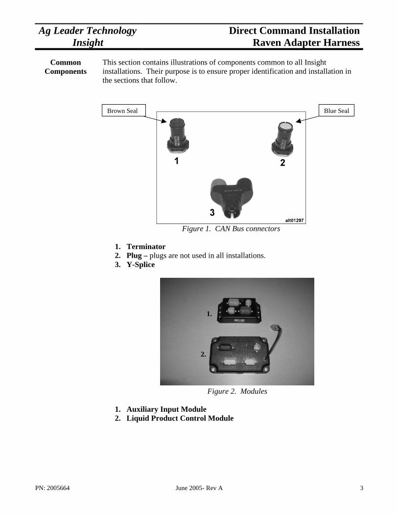
This section contains illustrations of components common to all Insight installations. Their purpose is to ensure proper identification and installation in the sections that follow. l
PN: 2005664
Brown Seal
Figure 1. CAN Bus connectors
1. Terminator 2. Plug – plugs are not used in all installations. 3. Y-Splice
Figure 2. Modules
1. Auxiliary Input Module 2. Liquid Product Control Module
June 2005- Rev A
Blue Sea
1.
2.
3

Direct Command Installation Ag Leader TechnologyRaven Adapter Harness Insight
4 June 2005—Rev A PN: 2005664

Ag Leader Technology Direct Command InstallationInsight Raven Adapter Harness
PN: 2005664 June 2005- Rev A 5
Direct Command Installation Ag Leader TechnologyRaven Adapter Harness Insight
Installing Switch Box for Raven 440/450
Systems
Parts required for procedure: • (1) Display PN: 4000100 • (1) Switch Box PN: 4000434 • (1) Switch Box Bracket PN: 4000422 • (1) Hardware Kit PN: 2001352-1
Note: The switch box will be used when replacing a Raven 440 or 450 console. Skip this step if you have a Raven 460 or 660 console.
Step-by-Step for Installing Switch
Box for Raven 440/450 Systems
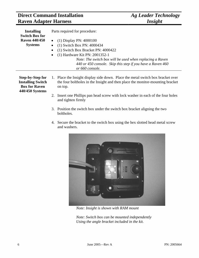
1. Place the Insight display side down. Place the metal switch box bracket over the four boltholes in the Insight and then place the monitor-mounting bracket on top.
2. Insert one Phillips pan head screw with lock washer in each of the four holes
and tighten firmly 3. Position the switch box under the switch box bracket aligning the two
boltholes. 4. Secure the bracket to the switch box using the hex slotted head metal screw
and washers.
Note: Insight is shown with RAM mount Note: Switch box can be mounted independently Using the angle bracket included in the kit.
6 June 2005—Rev A PN: 2005664

Ag Leader Technology Direct Command InstallationInsight Raven Adapter Harness
Installing Monitor
Parts required for procedure: • (1) Display PN: 4000100 • (1) Display mounting kit
Note: Monitor can be mounted using the U bracket included in the monitor kit or purchase a RAM mount kit PN: 4100100 at the operators preference
Assembling
Harness
Parts required for procedure: • (1) Display Cable PN: 4000216-1 • (1) Distribution Cable PN: 4000217-1 • (1) Power Control Relay PN: 4000379 • (1) CAN Bus Stub 8” PN: 4000450-1 • (1) CAN Bus Stub 1’ PN: 4000219-1 • (1) CAN Bus Cable PN: 4000218-1 • (2) Y-splice PN: 4000137 • (1) Terminator PN: 4000141
Step-by-Step Procedure for
Assembling the Harness
1. Connect the smaller end of the Display cable PN 4000216-10 to the Insight. 2. Connect the larger 24-pin connection lead to the distribution cable PN
4000217-1. 3. Plug the Power control relay PN 4000379 into the distribution cable in the
four-pin square weather pack connection. Press together until the latch snaps, locking the two together.
4. Connect the first Y-splice connector to the distribution cable. The single end
will plug into the distribution cable.
Note: To properly connect the Y splice firmly pinch the metal clip against the plastic connection and then mate the ends
5. Plug the one foot CAN bus stub PN 4000219-1 into the gray connector of the
Y splice. 6. Next, plug the CAN extension cable PN 4000218-1 into the black connection
of the Y-splice 7. Plug in the second Y-splice to the end of the CAN extension cable.
PN: 2005664 June 2005- Rev A 7
Direct Command Installation Ag Leader TechnologyRaven Adapter Harness Insight
8. Plug the eight inch CAN bus stub PN 4000450-1 to the gray connector of the
Y splice 9. Cap the black end of the Y-splice with a terminator PN 4000141.
Installing Raven
Harness Parts required for procedure: • (1) Raven Adapter harness PN: 4000425 • (1) Existing Raven harness • (1) Assembled CAN Bus harness
Step-by-Step Procedure for
Installing Raven Harness
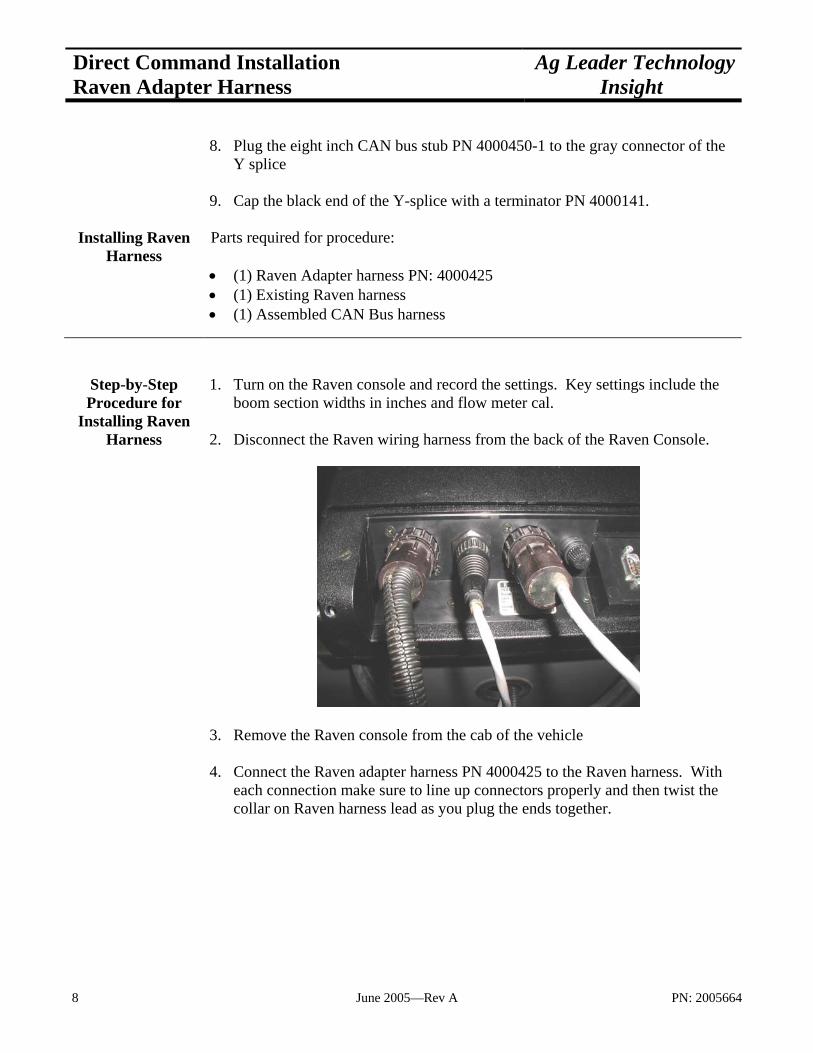
1. Turn on the Raven console and record the settings. Key settings include the boom section widths in inches and flow meter cal.
2. Disconnect the Raven wiring harness from the back of the Raven Console.
3. Remove the Raven console from the cab of the vehicle 4. Connect the Raven adapter harness PN 4000425 to the Raven harness. With
each connection make sure to line up connectors properly and then twist the collar on Raven harness lead as you plug the ends together.
8 June 2005—Rev A PN: 2005664
Ag Leader Technology Direct Command InstallationInsight Raven Adapter Harness
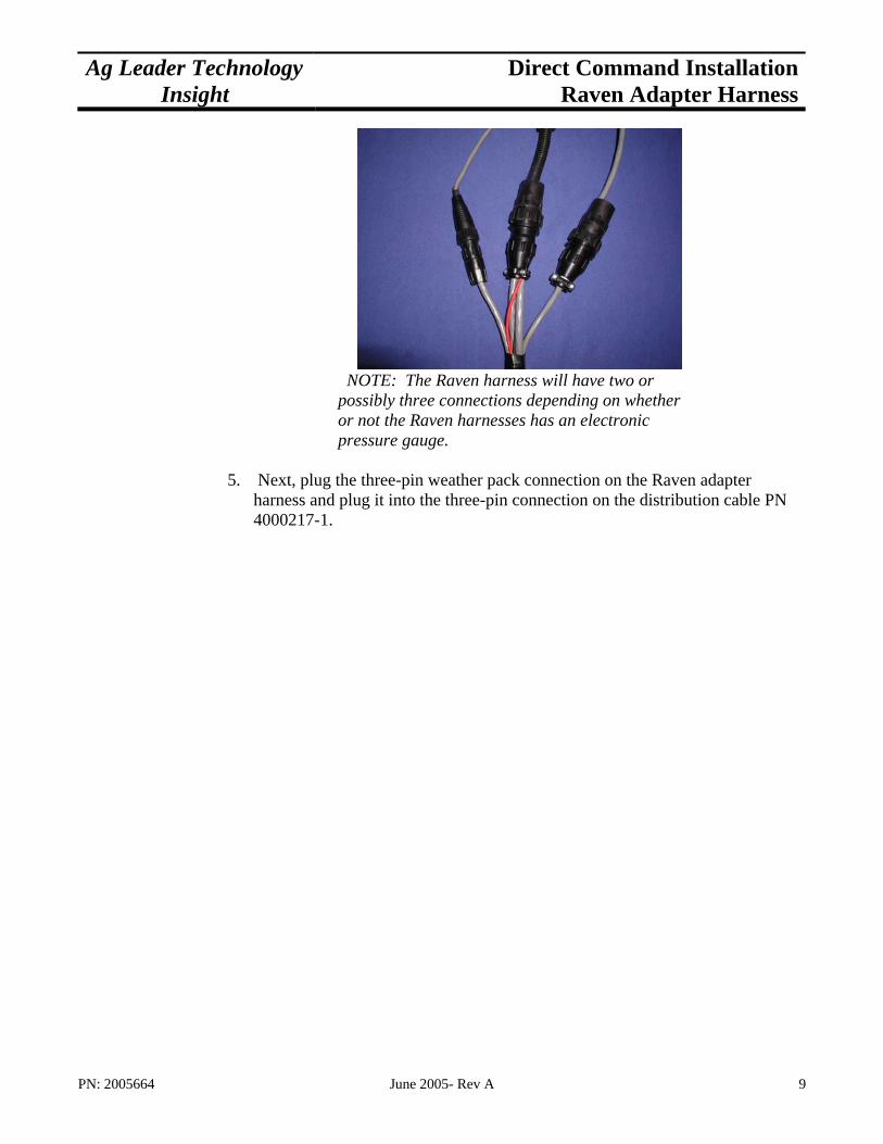
NOTE: The Raven harness will have two or possibly three connections depending on whether or not the Raven harnesses has an electronic pressure gauge.
5. Next, plug the three-pin weather pack connection on the Raven adapter
harness and plug it into the three-pin connection on the distribution cable PN 4000217-1.
PN: 2005664 June 2005- Rev A 9
Direct Command Installation Ag Leader TechnologyRaven Adapter Harness Insight
Installing AIM &LCM Modules
Parts required for procedure: • (1) Auxiliary Input Module PN: 4000437 • (1) Liquid Product Control Module PN: 4000394 • (1) Assembled CAN Harness • (1) Raven Adapter harness PN: 4000425
Step-by-Step for Liquid Control
Module installation
1. Locate the modules in the cab of the vehicle as for personal convenience. 2. Begin connecting the Raven adapter harness to the Liquid product control
module (LCM) by selecting the harness lead with three large connectors on it. 3. First, plug the black female connector into the mating black connector on the
LCM labeled AUXILLARY. 4. Next, plug in the 12-pin gray female connector into the mating gray connector
labeled BOOM. 5. Then plug in the eight pin gray female connector into the mating gray
connector labeled CHANNEL 1 6. Finally, plug the two pin female connector to the two pin male connector that
extends out of the LCM casing. 7. Also plug in the gray female connector of the CAN Stub PN: 4000450-1 into
the mating four-pin connector labeled CAN BUS.
Step-by-Step for Auxiliary Input
Module installation
1. Using the smaller lead of the Raven adapter harness that contains two connections, plug in the gray female connector to the mating six pin gray connection labeled RADAR.
2. Second, plug in the maroon female connector to the mating maroon
connection labeled SWITCH B. 3. Finally, insert the gray female CAN stub connection PN 4000219-1 into the
mating connector labeled CAN BUS on the auxiliary input module.
10 June 2005—Rev A PN: 2005664
Ag Leader Technology Direct Command InstallationInsight Raven Adapter Harness
Connecting Auxiliary Boom Switch cable for Raven 460/660
systems
Parts required for procedure: • (1) Auxiliary Input Module PN: 4000437 • (1) Auxiliary Input Module Generic Switch Cable PN: 4000515-5 or 4000527 • (1) Voltmeter or Test Light
Note: The boom switch cable will be used to connect to existing boom switches when replacing a Raven 460 or 660 console.
Step-by-Step for
Connecting Auxiliary Boom
Switch cable
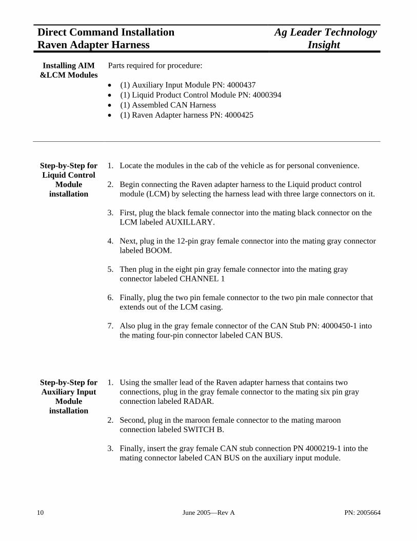
1. Open access panels to access the bottom of the original manufacturers boom switches.
2. Use a test light or voltmeter to determine which wire in the bottom of the
switch is the switched power (12v) going out to the boom valve. 3. Disconnect the wire that is on the switched terminal of the switch.
4. Replace the removed wire with the Auxiliary Input Module generic switch cable (PN: 4000515-5 or 4000527-5) making sure to hook the “boom 1” lead to the boom 1 switch in the console.
5. Use electrical tape to insulate the disconnected wire from sprayer harness
removed in step 3. This wire will stay permanently disconnected. 6. Repeat steps 3 through 5 for each of the boom switches.
PN: 2005664 June 2005- Rev A 11

Direct Command Installation Ag Leader TechnologyRaven Adapter Harness Insight
7. The wire labeled “master” on the cable needs to be installed between the power side of a boom switch and the wire that plugs into the power side of the switch. Unplug the power wire from one of the boom switches. Plug the “master” wire into the power side of the switch and then plug the power wire into the pigtail on the master switch cable.
Connecting
Switch Cable 1. When finished with the switches route the harness out of the console in a
convenient way. 2. Next, Plug in the green female connector from the boom switch cable into the
mating green connection on the Auxiliary input module.
Single Pole Boom Switch Before Direct Command
Liquid Control Module
12V Switch
Auxiliary Input Module
Raven Adapter Harness 4000425 Boom Switch
Cable 4000515-5
Control signal Boom valve
After Direct Command
12V
460 or 660
Switch Control signal Boom valve
12 June 2005—Rev A PN: 2005664

Ag Leader Technology Direct Command InstallationInsight Raven Adapter Harness
Installing An Implement
Switch (Optional)
Parts required for procedure: • (1) Implement Switch • (1) Implement Switch Extension Cable • (1) Generic Cable Installation Kit
Note: If using auto swath on an implement that is raised out of the ground when not applying, it is recommended to install an implement switch on the toolbar. This will prevent the system from turning on product flow when the implement is out of the ground and the vehicle encounters unapplied area.
Step-by-Step Installing an Implement
Switch (Optional)
1. Decide on a location for mounting the implement switch. 2. When installing the implement switch the switch must be mounted so that
the lever is off center when in the implement is in the “application position.” If this can be done then skip to step 7.
3. If the switch cannot be mounted this way then the wiring in the switch must
be changed. To do this first, open the switch casing.
Center
Off Center
PN: 2005664 June 2005- Rev A 13
Direct Command Installation Ag Leader TechnologyRaven Adapter Harness Insight
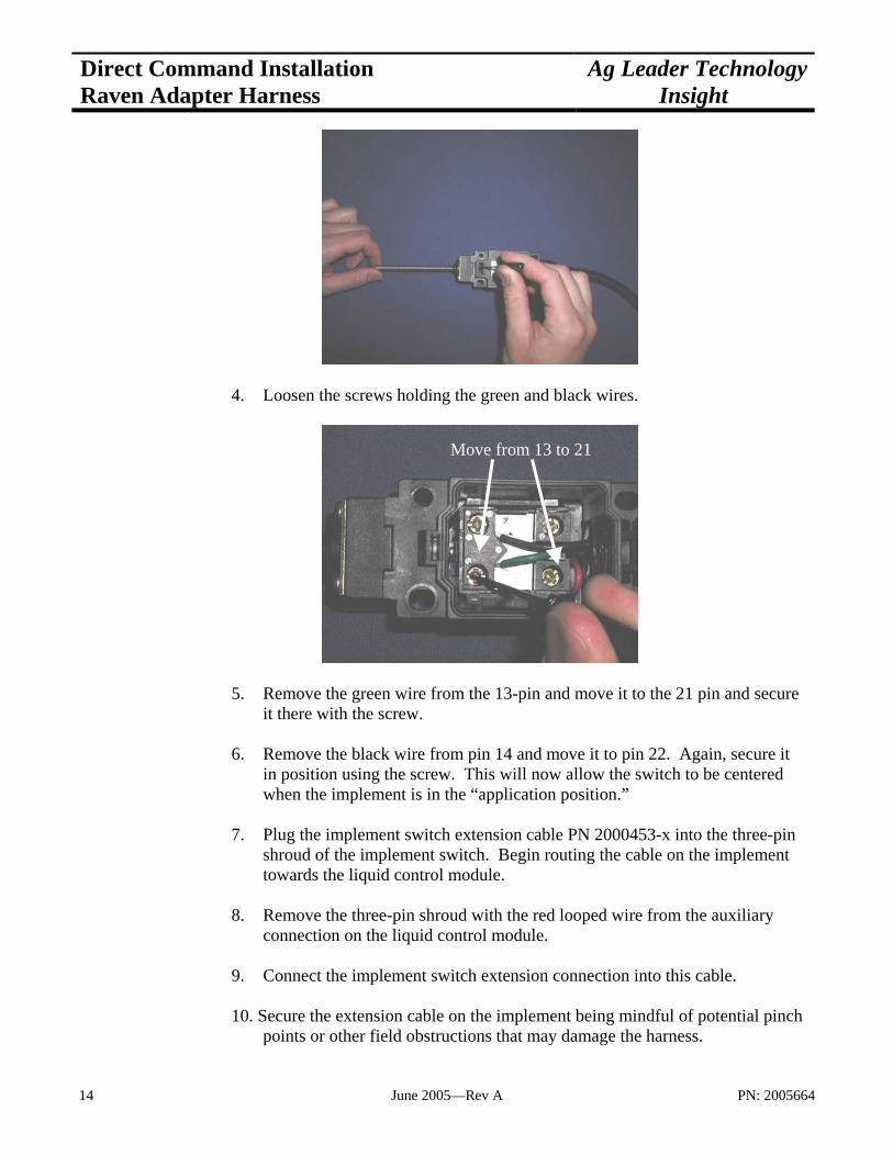
4. Loosen the screws holding the green and black wires.
5. Remove the green wire from the 13-pin and move it to the 21 pin and secure
it there with the screw. 6. Remove the black wire from pin 14 and move it to pin 22. Again, secure it
in position using the screw. This will now allow the switch to be centered when the implement is in the “application position.”
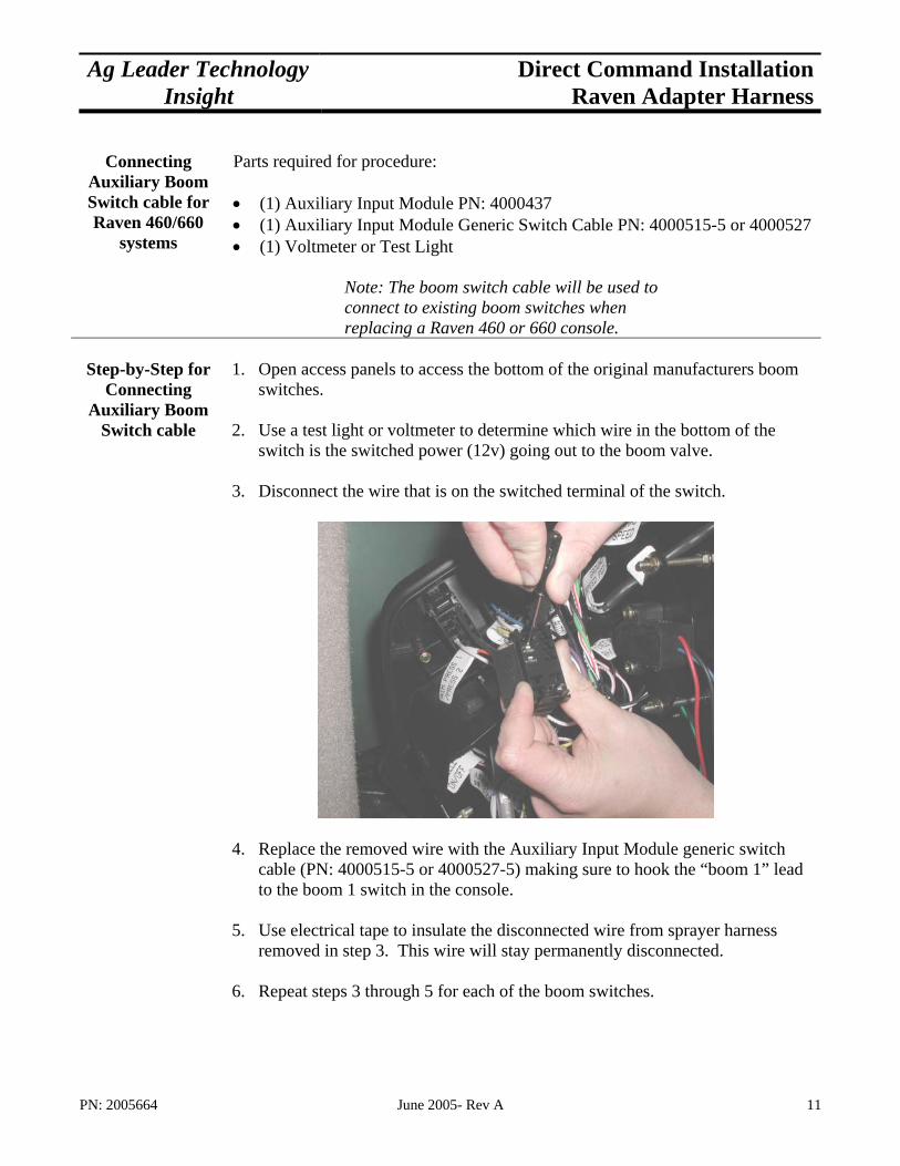
7. Plug the implement switch extension cable PN 2000453-x into the three-pin
shroud of the implement switch. Begin routing the cable on the implement towards the liquid control module.
8. Remove the three-pin shroud with the red looped wire from the auxiliary
connection on the liquid control module. 9. Connect the implement switch extension connection into this cable. 10. Secure the extension cable on the implement being mindful of potential pinch
points or other field obstructions that may damage the harness.
Move from 13 to 21
14 June 2005—Rev A PN: 2005664

Ag Leader Technology Direct Command InstallationInsight Raven Adapter Harness
Setting Up the Monitor
1. Refer to the Quick Reference guide for setting up the monitor.
PN: 2005664 June 2005- Rev A 15