after nachtigall, 1978. unun ‘quasi-steady’ analysis (blade element theory) nn drag = drag n n...
TRANSCRIPT

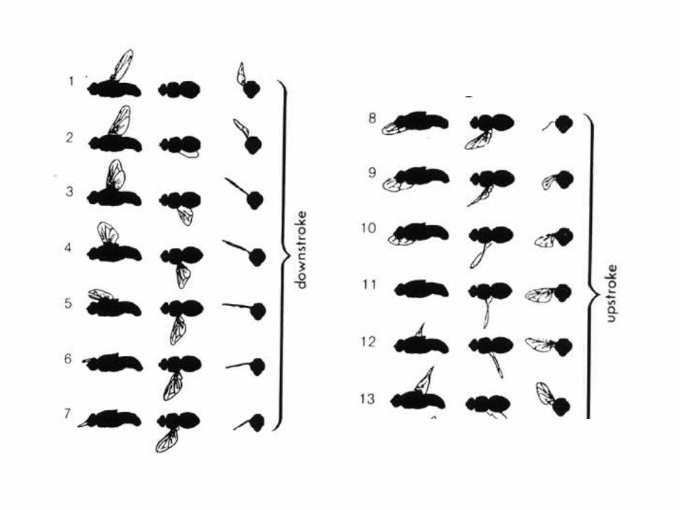
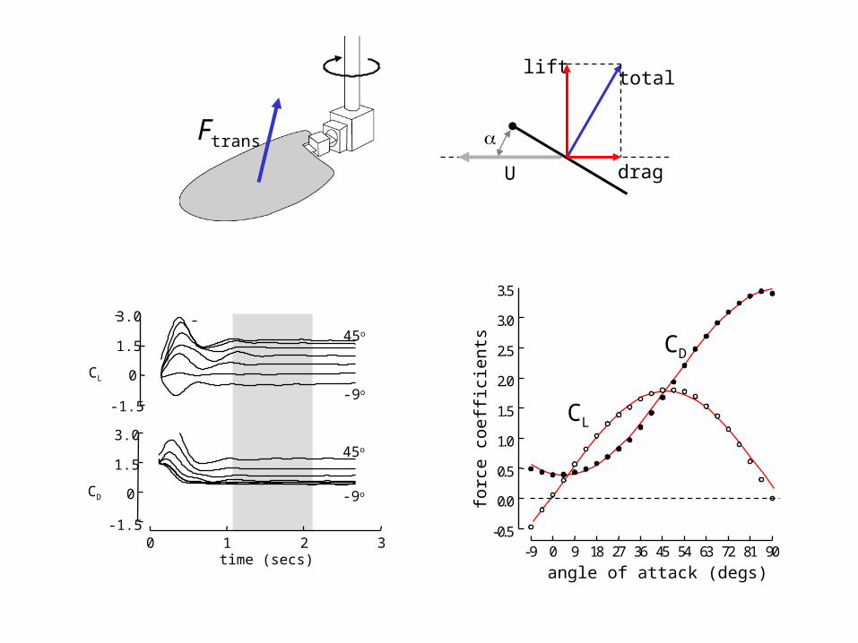
after Nachtigall, 1978
Un
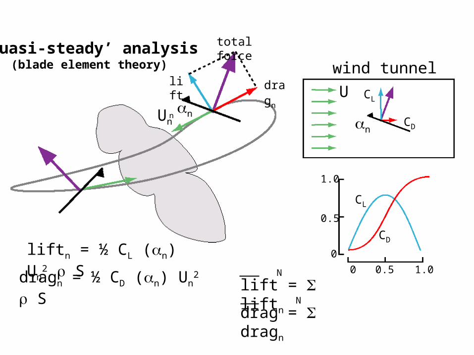
‘Quasi-steady’ analysis(blade element theory)
n
drag = dragn
N
lift = liftn
N
total force
liftn dragn
liftn = ½ CL (n) Un2 S
dragn = ½ CD (n) Un2 S
wind tunnel
CL
CD
0
0.5
1.0
0 0.5 1.0
U
nCD
CL

1.3
0.8
0 1 2 3 4-1
0
1
2
3
drag coefficient
lift
coe
ffic
ient
locust
fc
fruit fly
f
c
crane fly
range needed to support flight
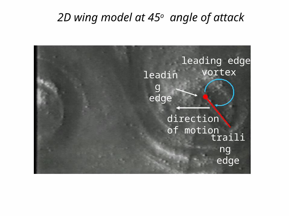
2D wing model at 45o angle of attack
leading edge
trailing edge
directionof motion
leading edge vortex
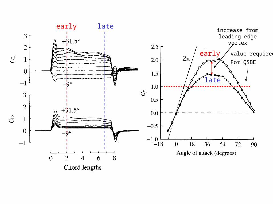
F
2
early late
early
late
increase fromleading edge
vortex
value required
For QSBE
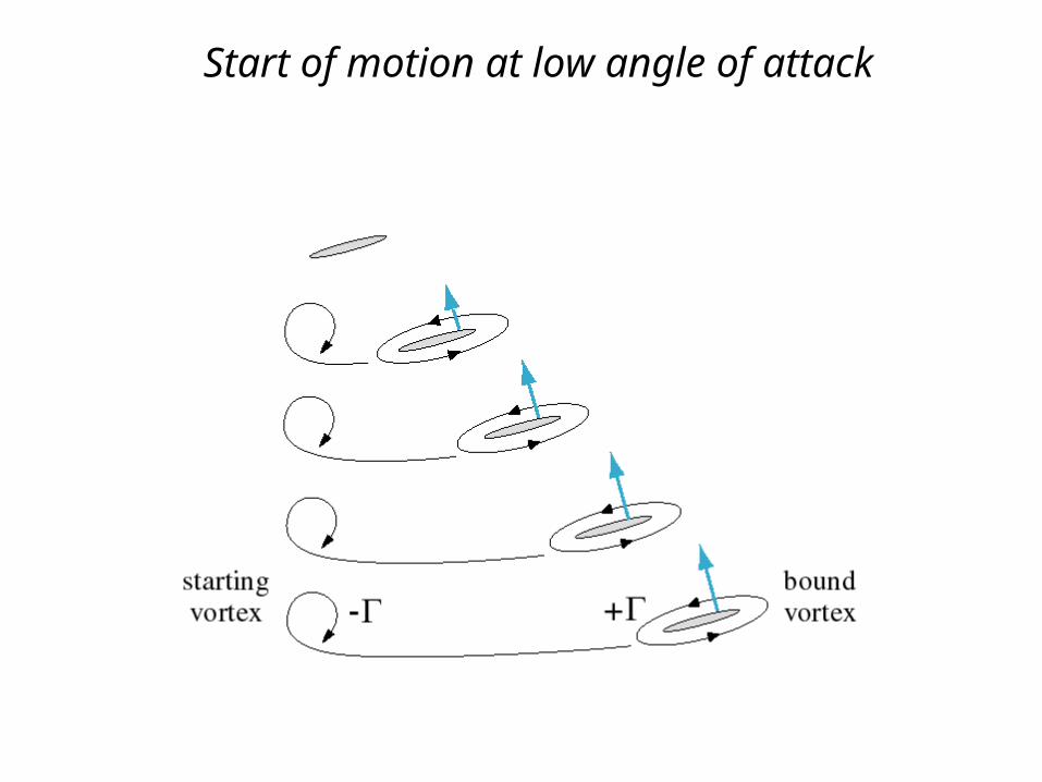
Start of motion at low angle of attack
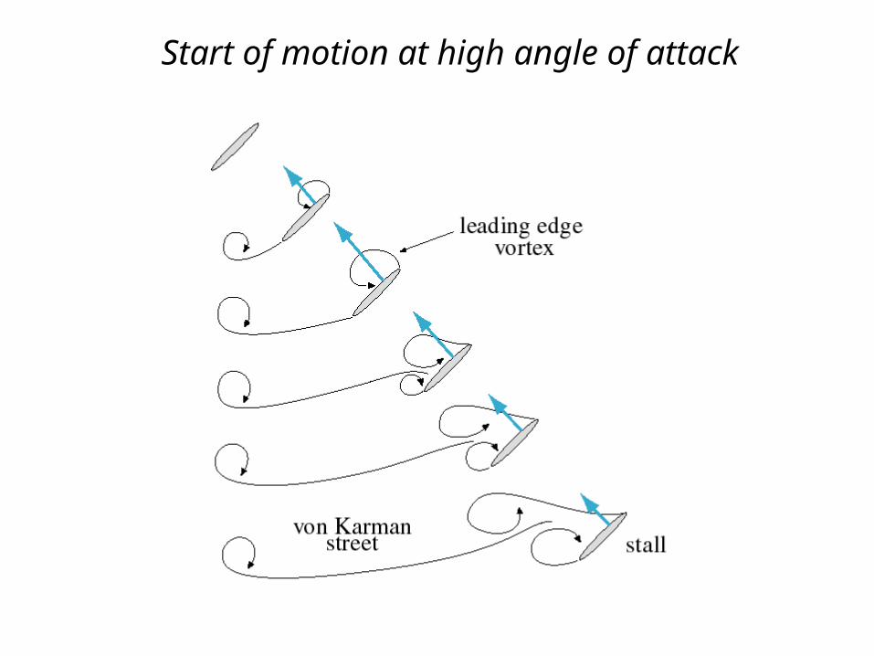
Start of motion at high angle of attack
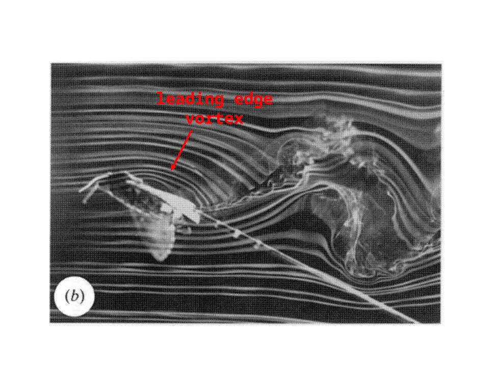
leading edgevortex
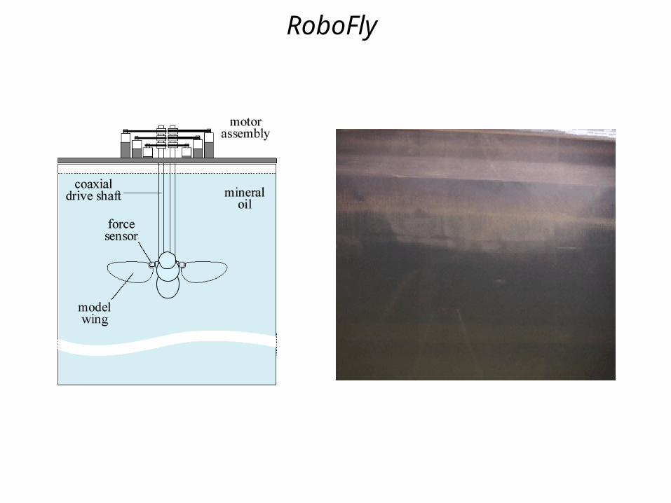
RoboFly
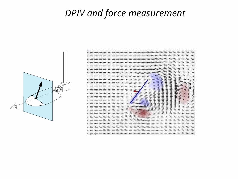
DPIV and force measurement
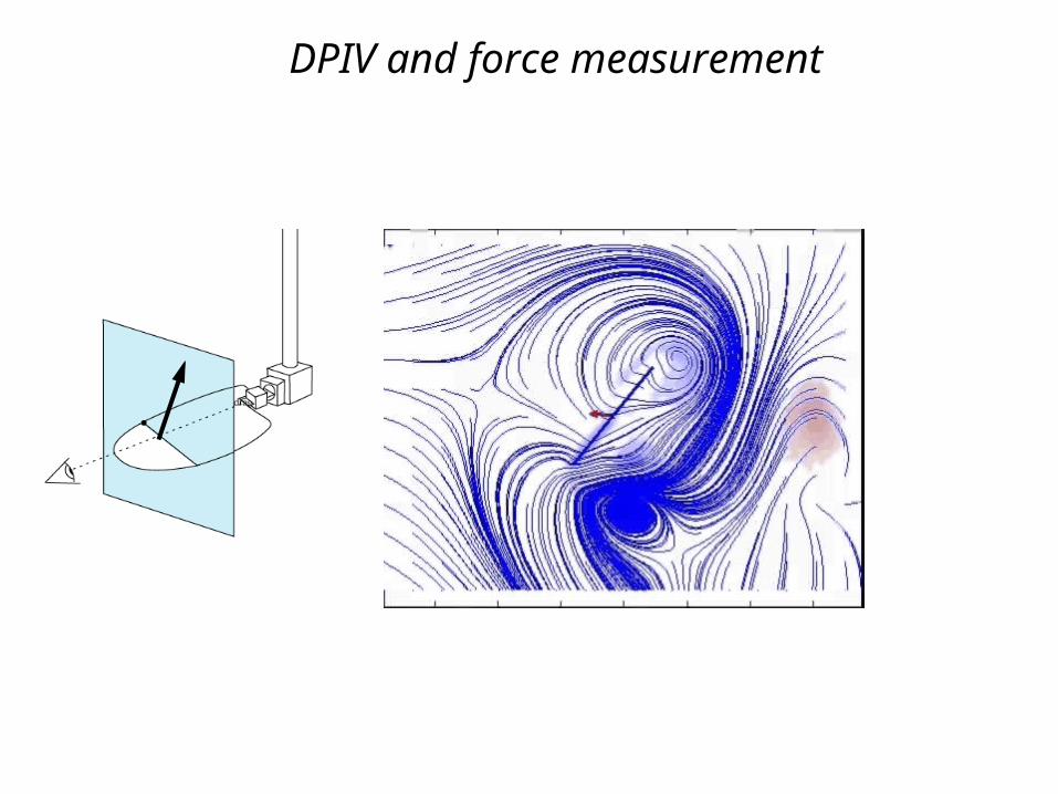
DPIV and force measurement
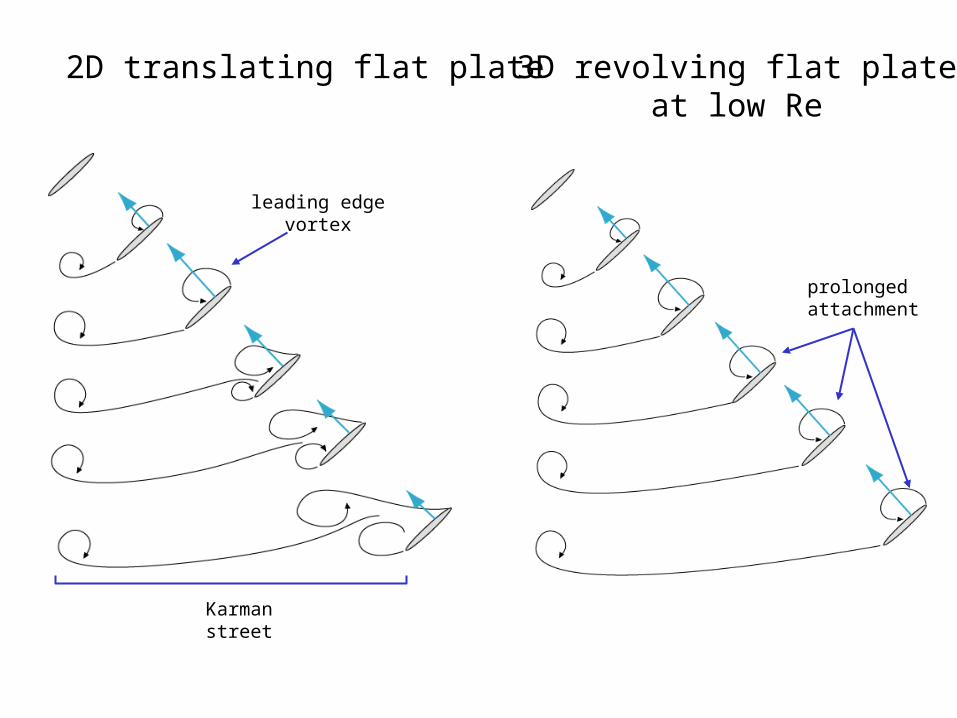
2D translating flat plate
Karmanstreet
leading edgevortex
3D revolving flat plateat low Re
prolonged attachment
-9 0 9 18 27 36 45 54 63 72 81 90
-0.5
0.0
0.5
1.0
1.5
2.0
2.5
3.0
3.5
angle of attack (degs)
forc
e co
effi
cien
ts
CL
CD
0 1 2 3
3.0
time (secs)
CD
CL
1.5
0
-1.5
3.0
1.5
0
-1.5
45o
-9o
-9o
45o
Ftrans
lift
total
dragU
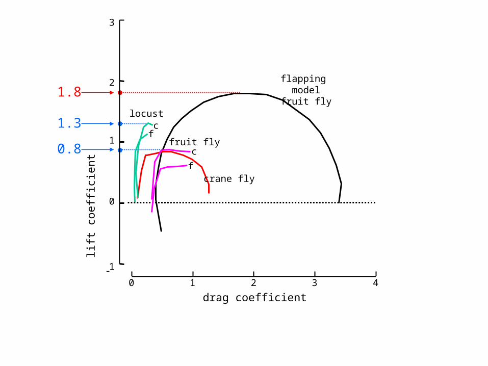
flapping modelfruit fly
1.8
1.3
0.8
0 1 2 3 4-1
0
1
2
3
drag coefficient
lift
coe
ffic
ient
locust
fc
fruit fly
f
c
crane fly

uvs.
constant angular velocity (72 deg/sec)
constant forwardvelocity (0.157 m/s)
CD
0 1 2 3 4-1
0
1
2
3
CL
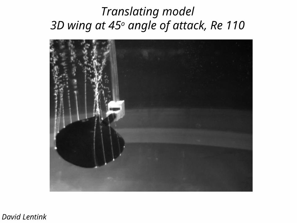
Translating model3D wing at 45o angle of attack, Re 110
David Lentink
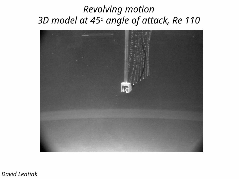
Revolving motion3D model at 45o angle of attack, Re 110
David Lentink
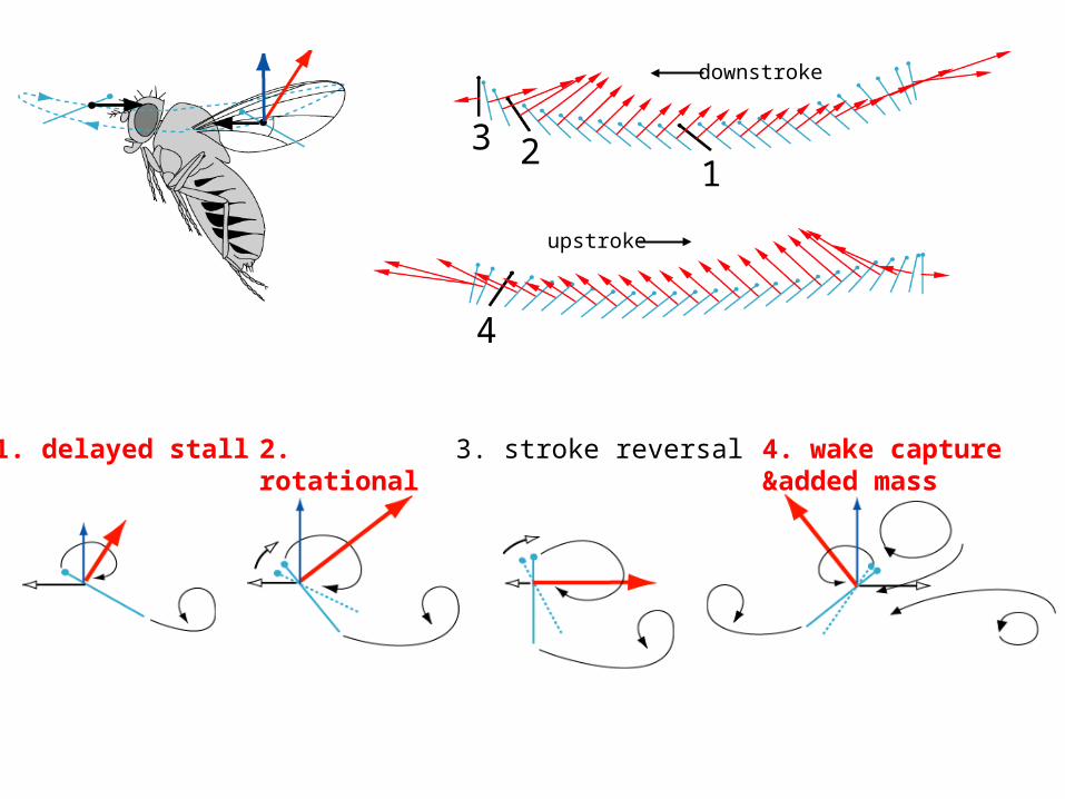
downstroke
upstroke
1. delayed stall
1
2. rotational lift
2
3. stroke reversal
3
4. wake capture&added mass
4
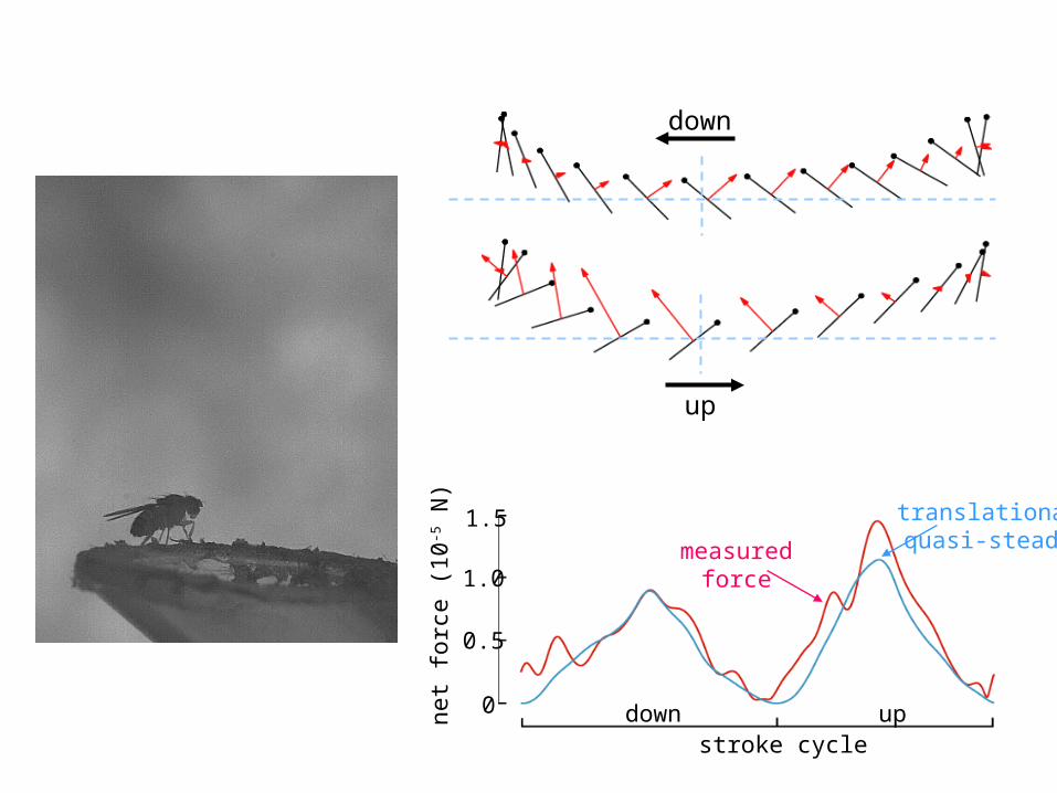
down
up
stroke cycleupdown
1.5
1.0
0.5
0net force (10-5 N)
measuredforce
translationalquasi-steady
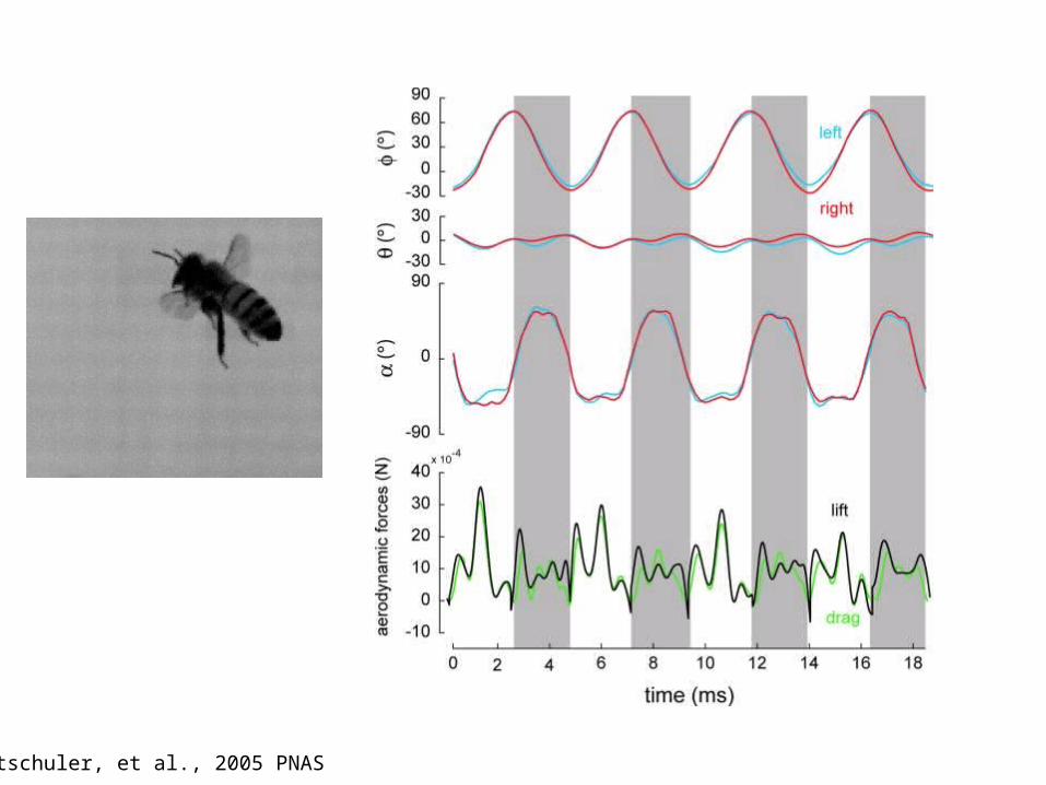
Altschuler, et al., 2005 PNAS

Dear Prof. Dickinson, July 28, 2006
I report on aviation for The Wall Street Journal and wonder if I could trouble you for a professional judgment.
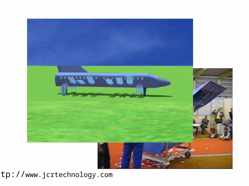
Some entrepreneurs attempting to build a large commercial aircraft with small flapping wings have approached me to write a story about their project, and I'm trying to get a sense of whether their idea is at all realistic. They say their design is based, in part, on your research and development work. But obviously there is a huge difference between simulating a tiny insect and building a 100-passenger aircraft. The company is called JCR Technology, in case you have come across them. Their website, which so far seems only to be in French, has information about their design and some computer-graphic simulations.
Would you or someone in your lab have a few minutes to look at this and assess whether it is realistic to develop or simply to far-fetched? I would be happy to call to discuss your work more, and how it has prompted this idea.
Best regards, Dan Michaels
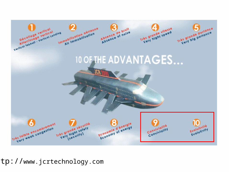
http://www.jcrtechnology.com
http://www.jcrtechnology.com
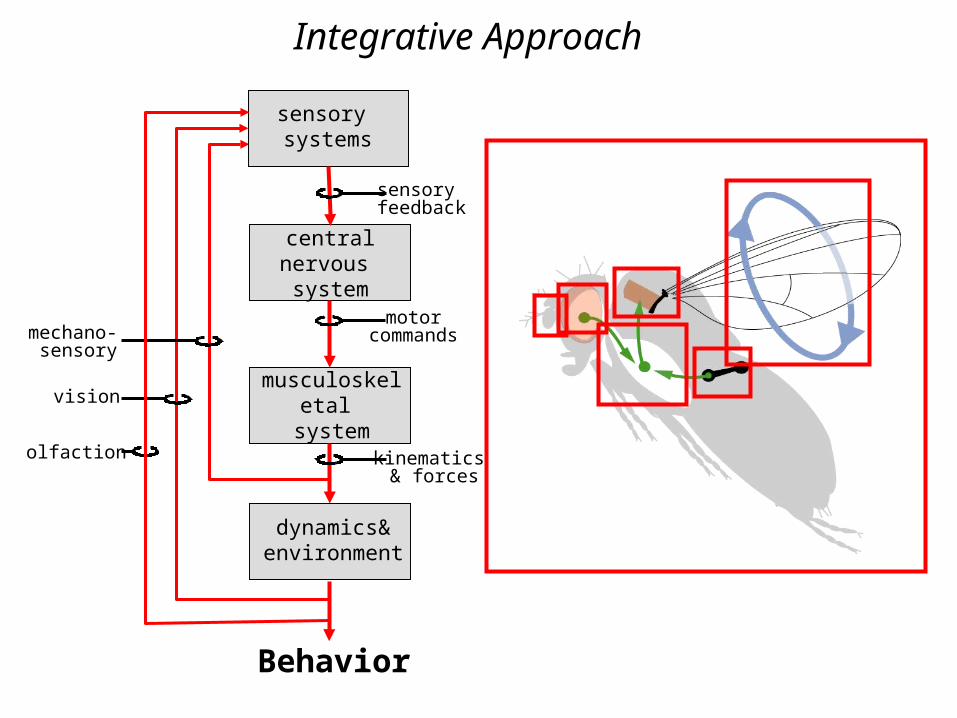
Integrative Approach
central nervous system
musculoskeletal system
motorcommands
dynamics& environment
kinematics & forces
Behavior
sensory systems
sensory feedback
olfaction
mechano-sensory
vision
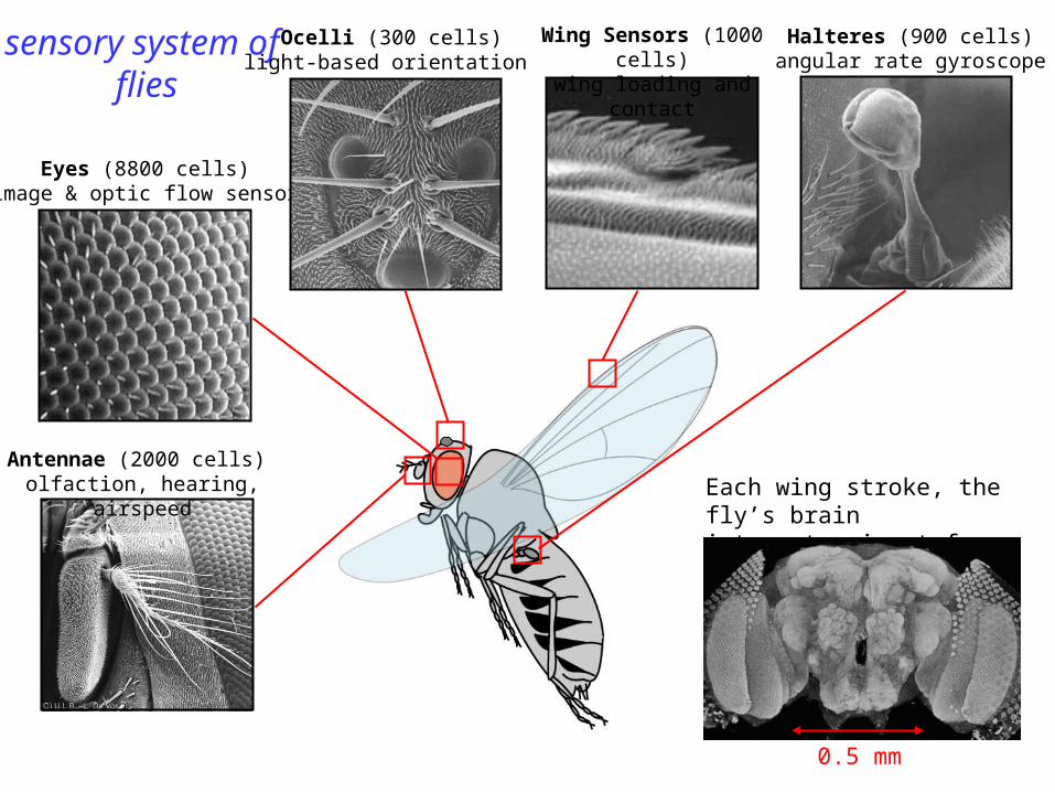
sensory system of flies
Each wing stroke, the fly’s brain integrates input from 15,000 cells.
Wing Sensors (1000 cells)wing loading and contact
Halteres (900 cells)angular rate gyroscope
Antennae (2000 cells) olfaction, hearing, airspeed
Eyes (8800 cells)image & optic flow sensor
Ocelli (300 cells)light-based orientation
0.5 mm
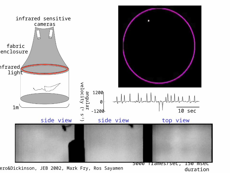
Tammero&Dickinson, JEB 2002, Mark Fry, Ros Sayamen
1m
infrared light
infrared sensitive cameras
fabric enclosure
10 sec-1200
1200
0
angu
lar
velo
city
(o s
-1)
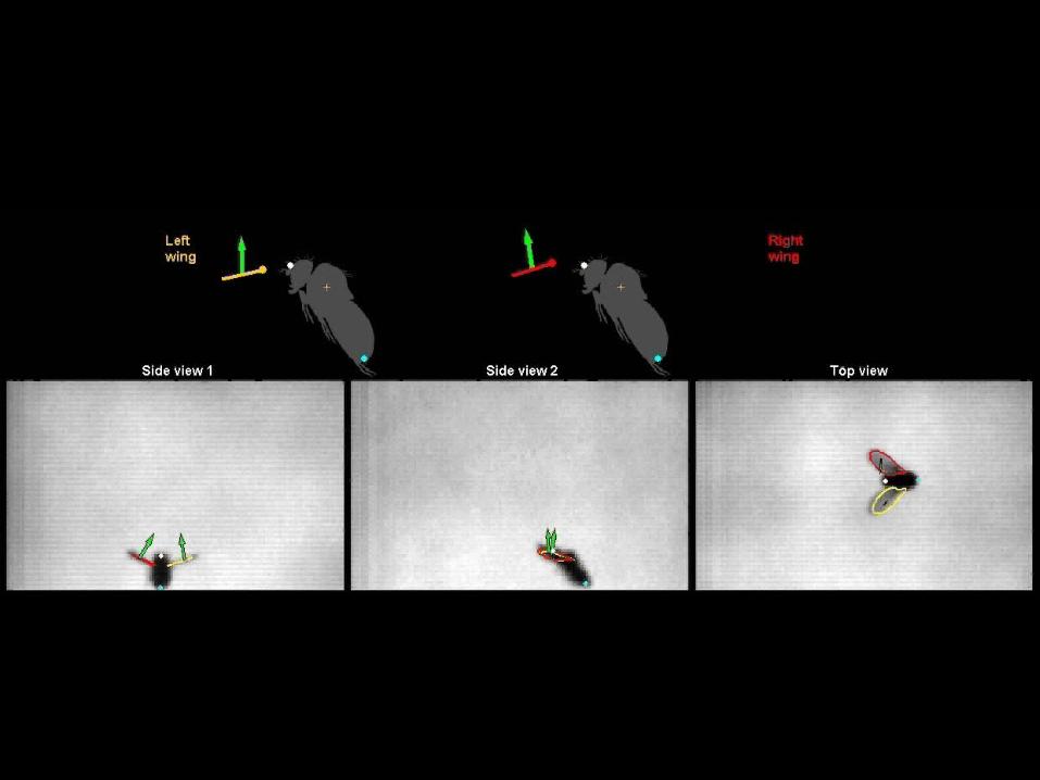
5000 frames/sec, 150 msec duration
top viewside view side view
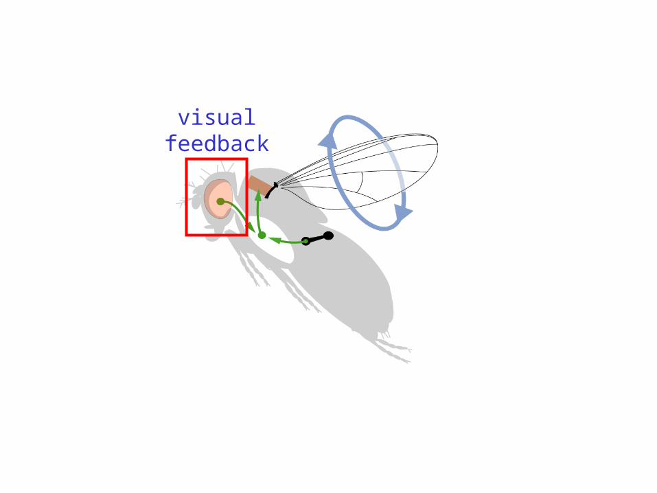
visualfeedback
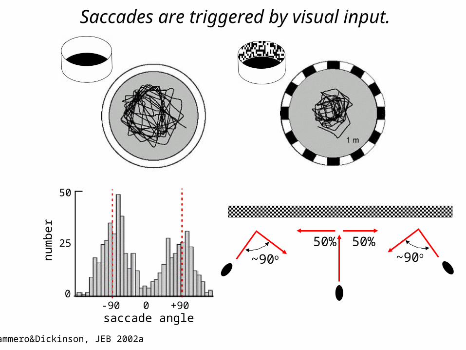
50% 50%~90onu
mbe
r
0
50
25
0 +90-90saccade angle
Saccades are triggered by visual input.
Tammero&Dickinson, JEB 2002a
~90o
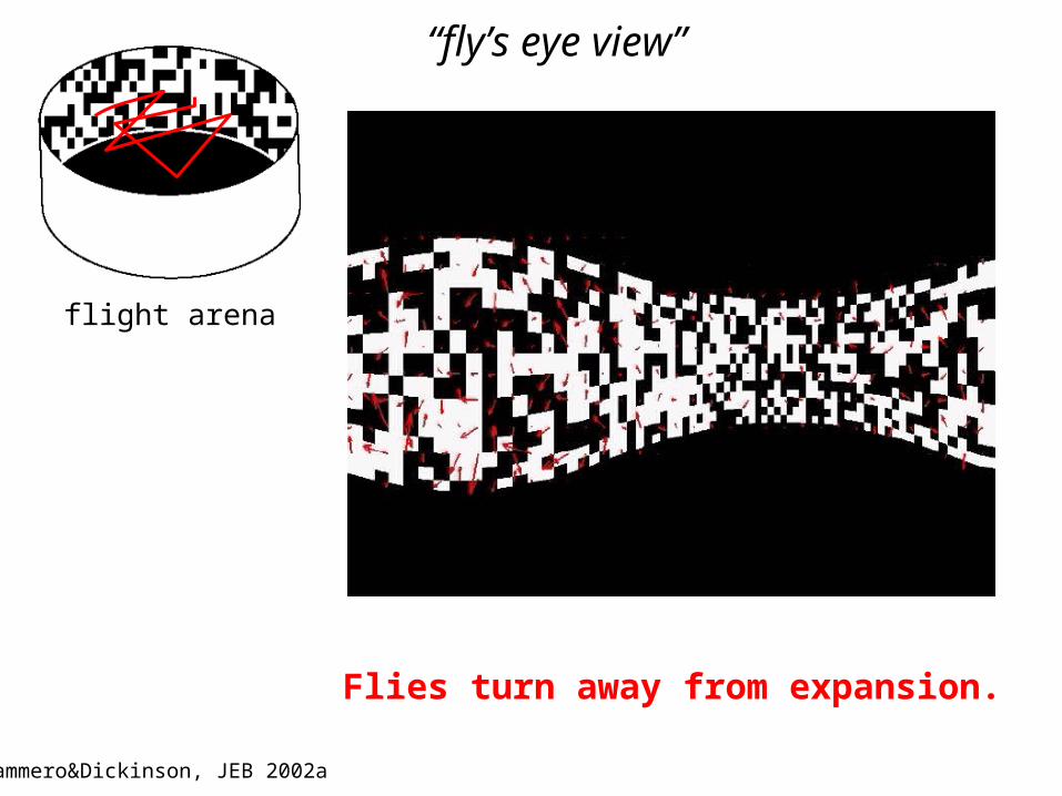
flight arena
“fly’s eye view”
Tammero&Dickinson, JEB 2002a
Flies turn away from expansion.
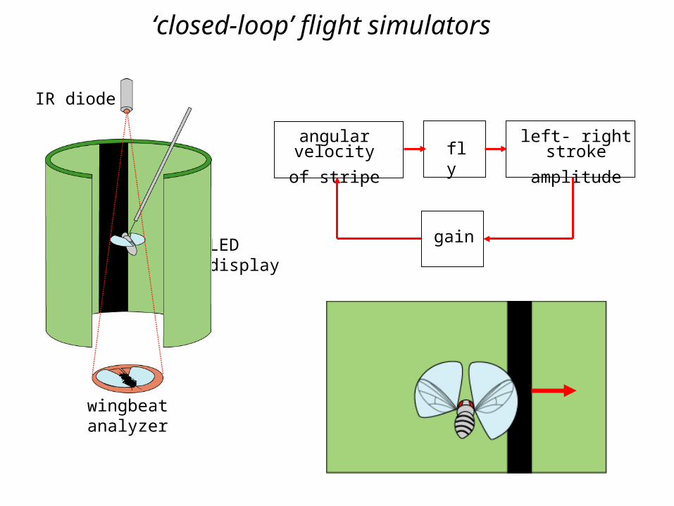
wingbeatanalyzer
LED display
angular velocity
of stripe
gain
left- right stroke
amplitudefly
IR diode
‘closed-loop’ flight simulators
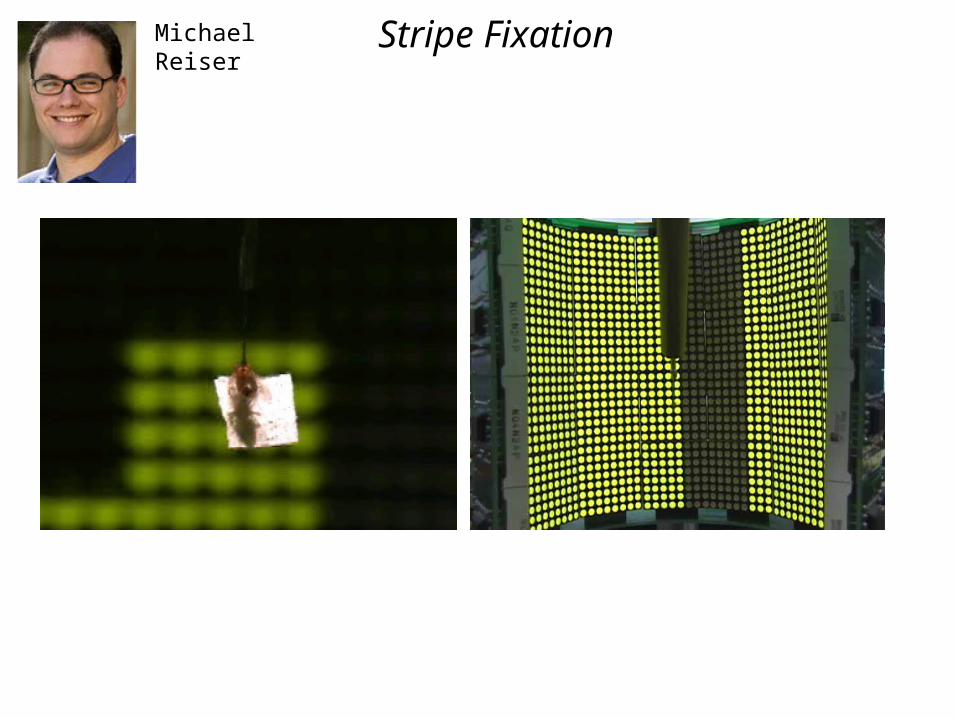
MichaelReiser
Stripe Fixation
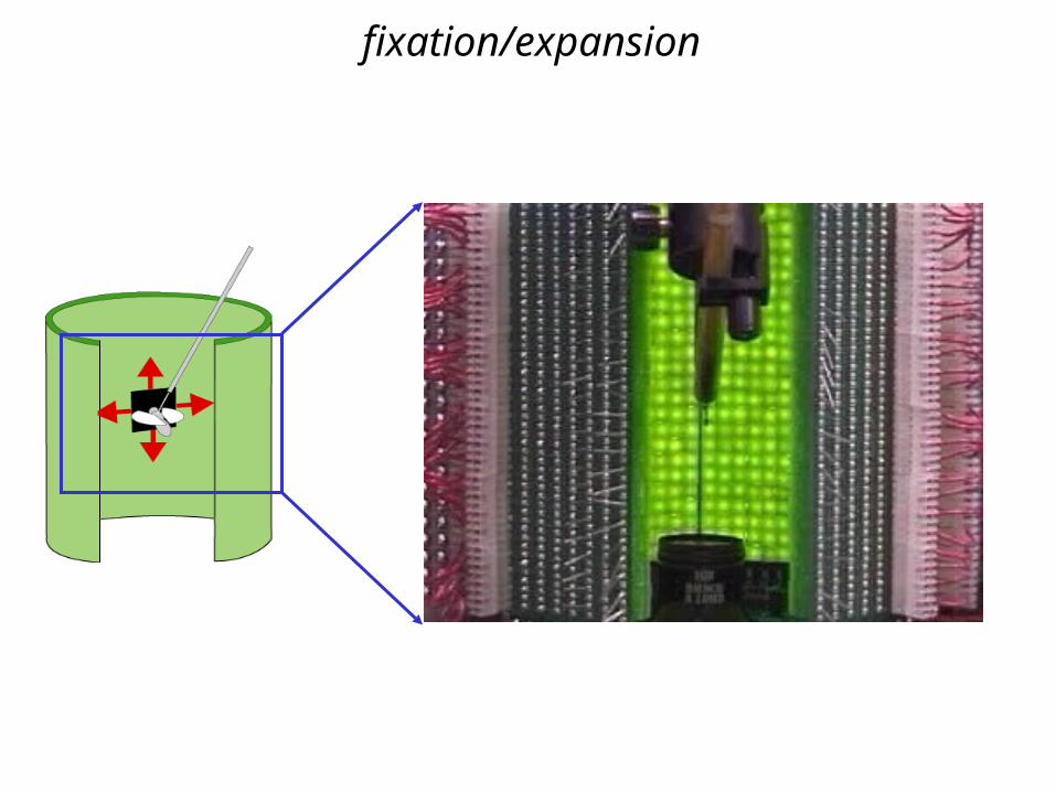
fixation/expansion
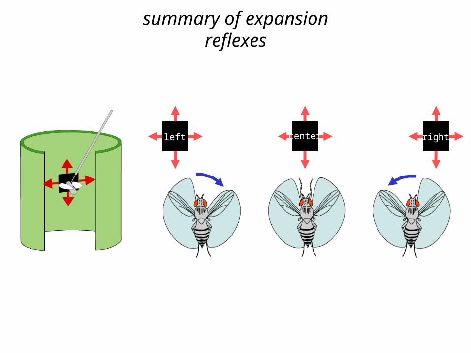
rightleft center
summary of expansion reflexes
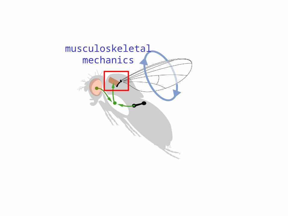
musculoskeletalmechanics
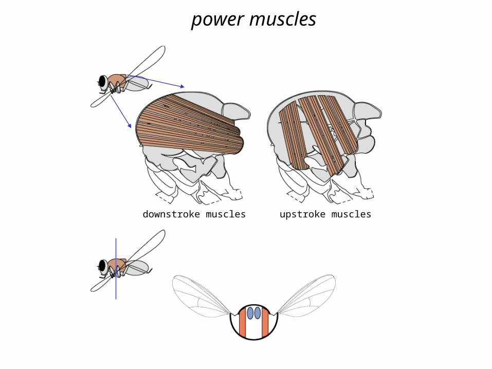
upstroke musclesdownstroke muscles
power muscles
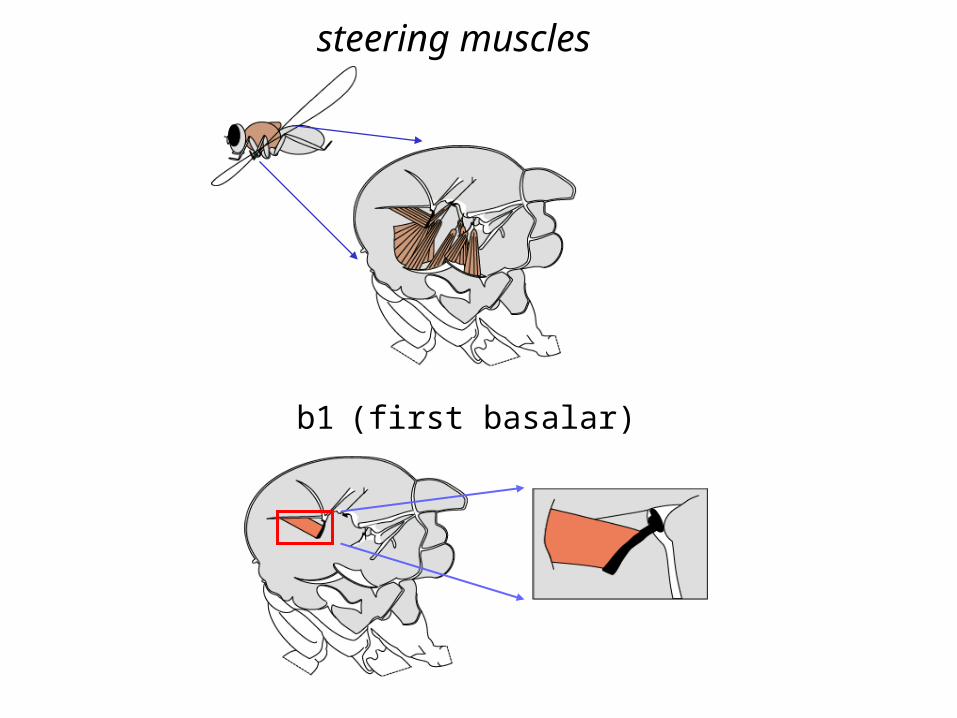
b1 (first basalar)
steering muscles
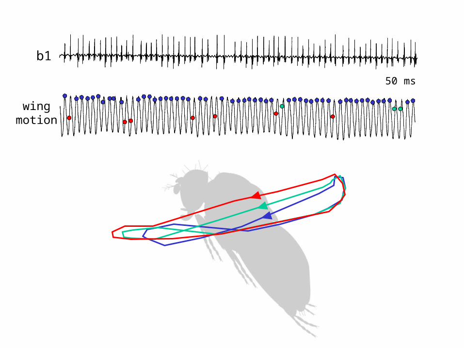
wingmotion
b1
50 ms
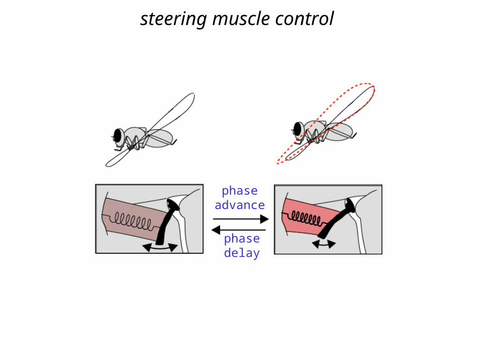
phaseadvance
phasedelay
steering muscle control
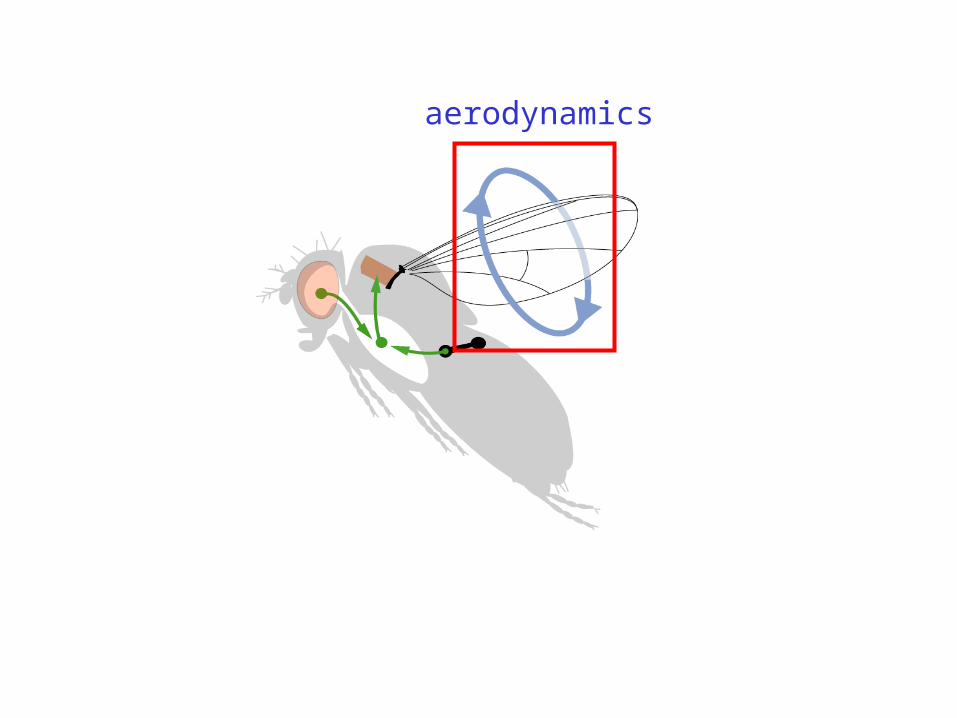
aerodynamics
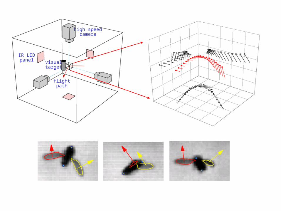
high speedcamera
IR LEDpanel
flightpath
visualtarget
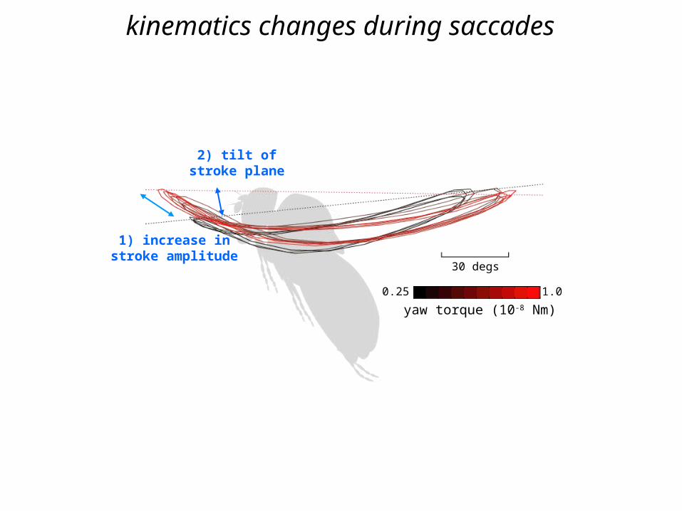
30 degs
1) increase instroke amplitude
2) tilt ofstroke plane
0.25 1.0
yaw torque (10-8 Nm)
kinematics changes during saccades
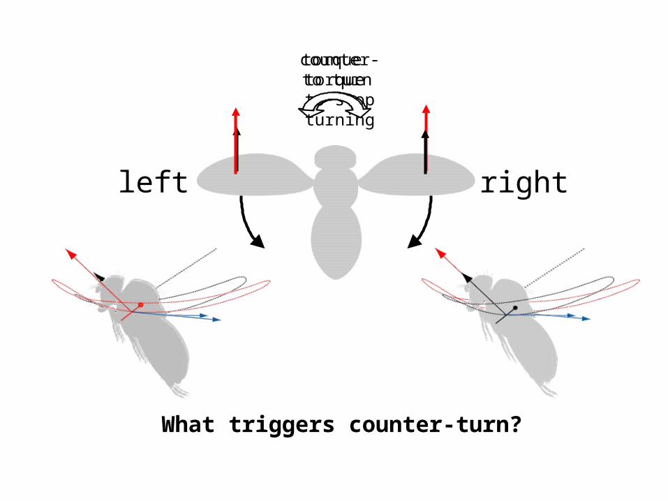
left right
counter-torque to stop turning
What triggers counter-turn?
torque to turn
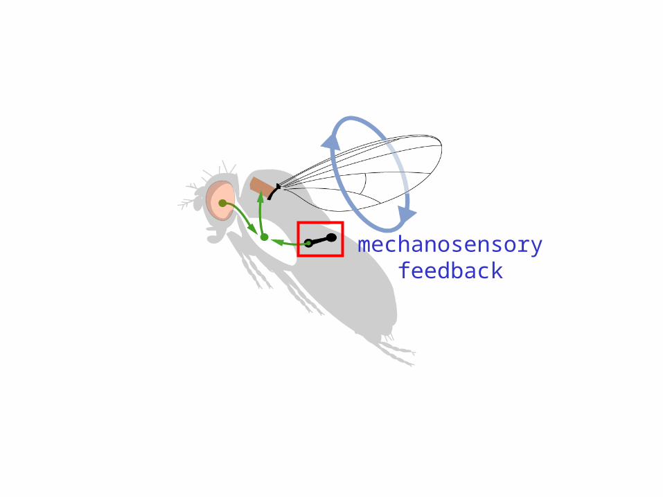
mechanosensoryfeedback
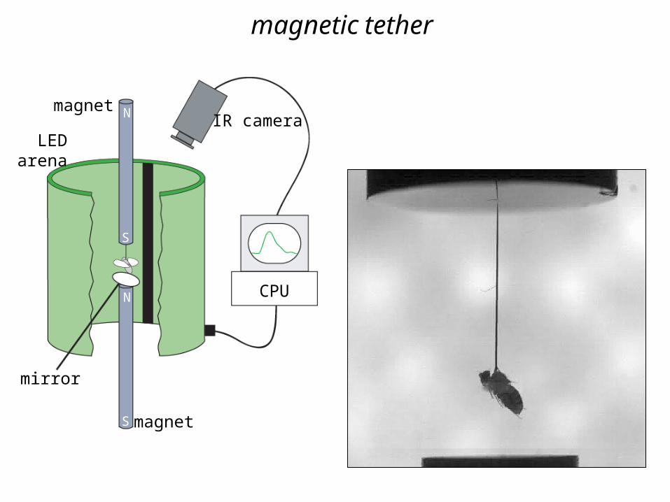
IR camera
CPU
magnet
magnet
LEDarena
mirror
N
S
N
S
magnetic tether
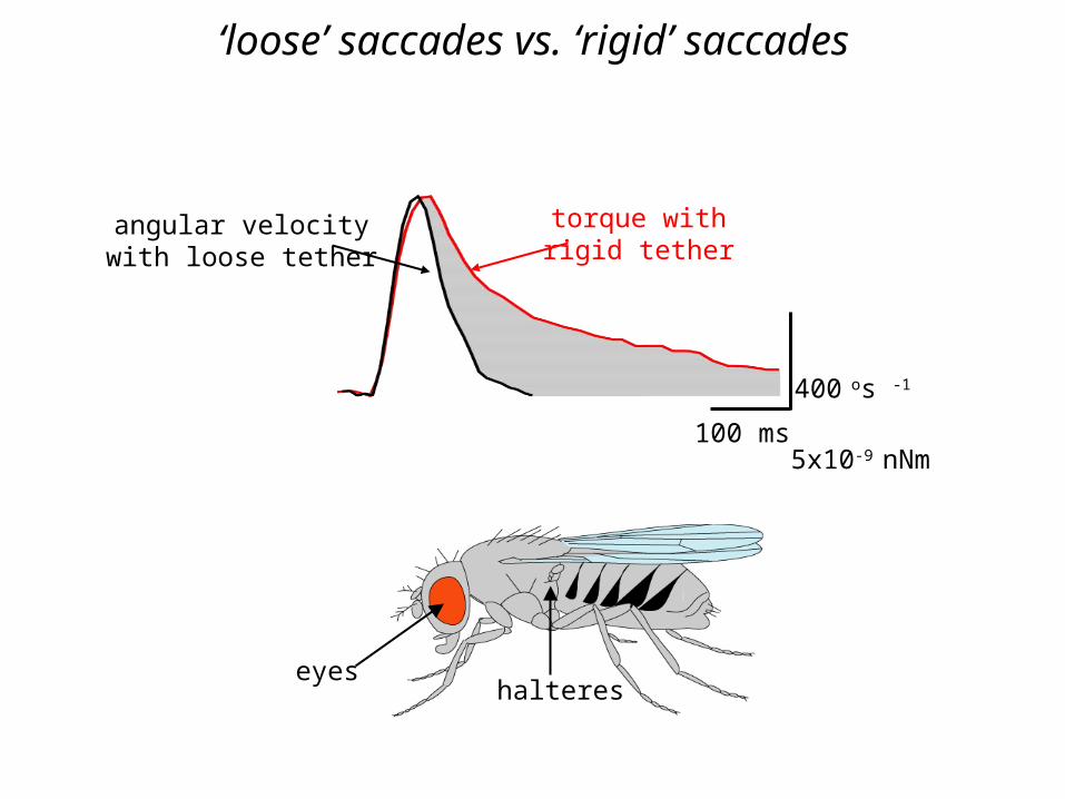
5x10⁻⁹ nNm
400 os -1
100 ms
torque withrigid tether
angular velocitywith loose tether
‘loose’ saccades vs. ‘rigid’ saccades
eyeshalteres
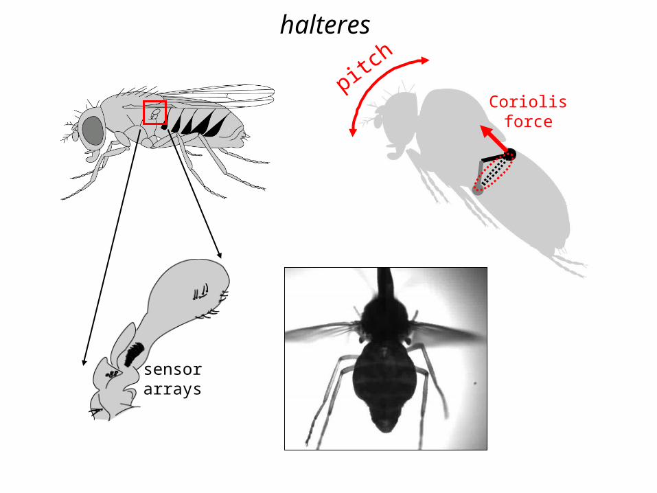
pitch
Coriolisforce
sensorarrays
halteres
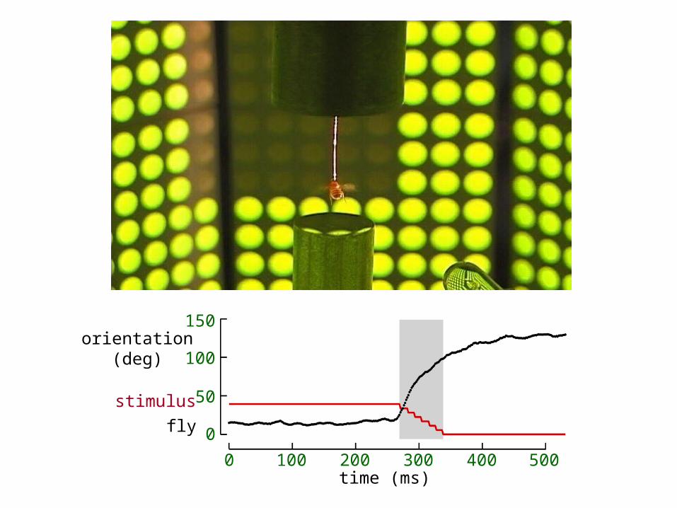
time (ms)0 100 200 300 400 500
orientation(deg)
0
50
100
150
stimulus
fly
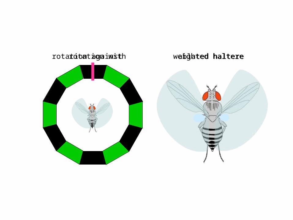
rotation withrotation against weighted haltereablated haltere
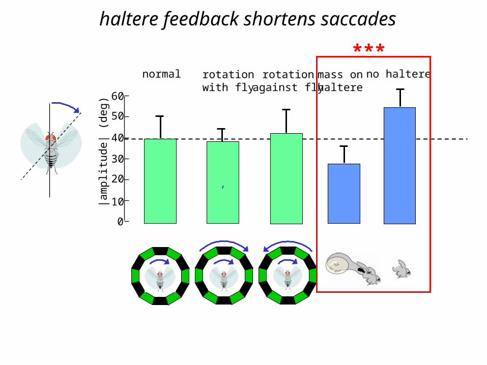
haltere feedback shortens saccades
|am
plit
ude|
(de
g)
0
10
20
30
40
50
60
normal
,
rotationwith fly
rotationagainst fly
mass onhaltere
no haltere
***
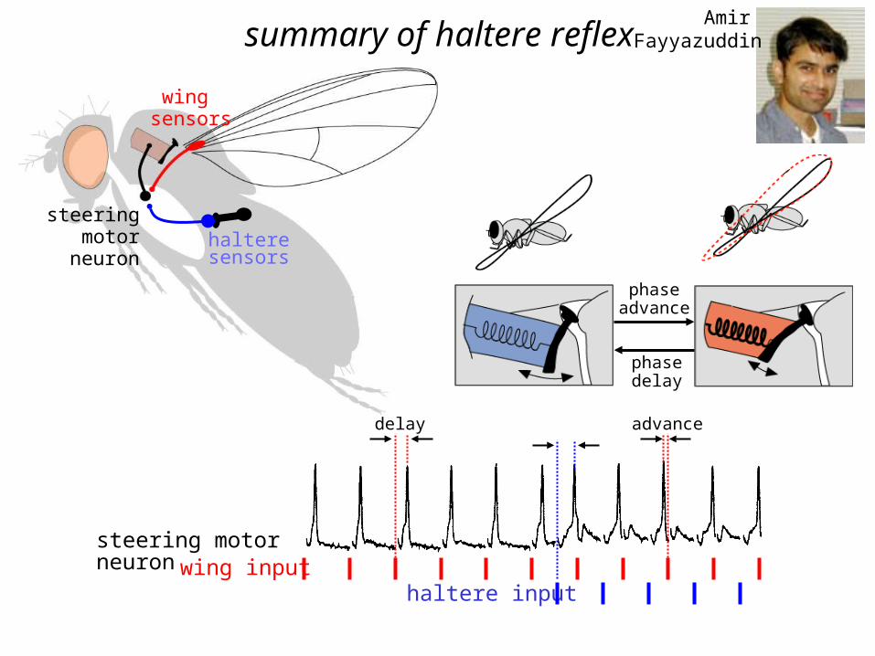
halteresensors
wing sensors
steering motor neuron
phaseadvance
phasedelay
summary of haltere reflex
steering motor neuronwing input
delay
haltere input
advance
Amir Fayyazuddin
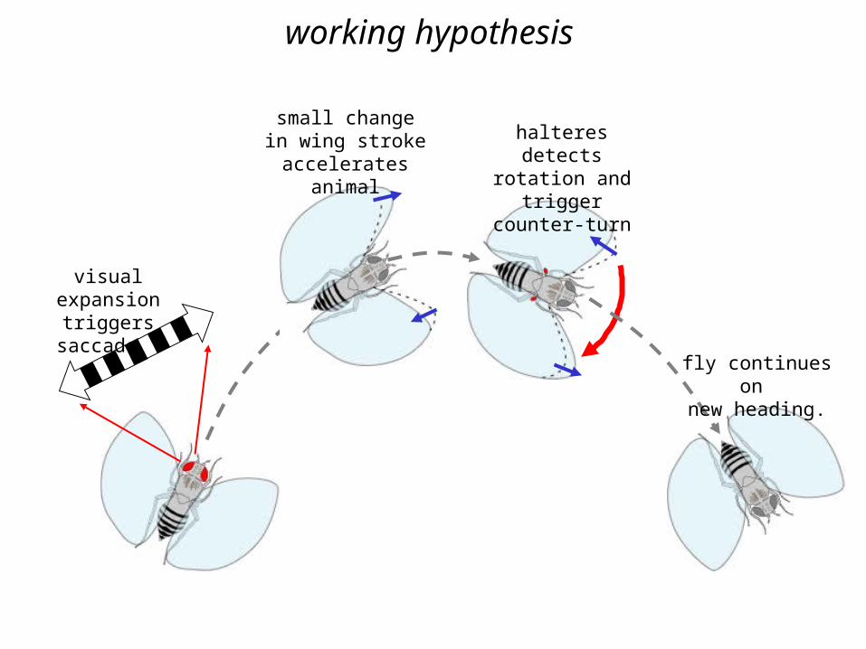
visual expansion triggers saccade
small change in wing stroke accelerates
animal
halteres detects rotation and trigger
counter-turn
fly continues on new heading.
working hypothesis