afs/afm60s pro
TRANSCRIPT

PR
OD
UC
T I
NF
OR
MA
TIO
N
AFS/AFM60S ProSAFE, EASY, FLEXIBLE: ENCODERS FOR SAFE POSITIONING.
Safety encoders

E n c o d E r s | s I c K 8021932/2020-05-20Subject to change without notice
2
AFs/AFM60s Pro Safety encoderS
Product descriptionthe afS/afM60S Pro is an absolute en-coder for functional safety. It fulfills very strict test criteria and is a certified safe-ty product up to SIL3/PL e. the absolute encoder supports the safety functions in accordance with Iec 61800-5-2 and impresses in particular with its safe positioning function. thanks to the high enclosure rating and large temperature range, the afS/afM60S Pro can be
used in harsh environments. With its SSI and sin/cos interface, it can be easily integrated into a range of different con-trols. In doing so, singleturn resolution, counting direction and other parameters can be adapted individually. The inte-grated error memory detects important ambient data which provides support during installation and maintenance.
at a glance• Certified up to SIL3 (IEC 61508), SIL-
CL3 (EN 62061), PL e (EN ISO 13849)• Single- or multiturn encoder with SSI
and sin/cos interface• Programmable, integrated error
memory
• Solid or hollow shaft encoder, mount-ing with key
• cable connection, M23 or M12 male connector
• operating temperature range: −30 °C ... +95 °C
Your benefits• Certified safety product that en-
sures the best possible protection for persons, machinery, and systems
• easy handling of safety functions with complete solutions from SIcK: Safe positioning with the afS/afM60S Pro and the fX3-Moc1 motion control module of the flexi Soft safety con-troller
• Positive and non-positive connec-tions for mechanical reliability
• Safety status conforming to the test basics of the Institute for occupation-al Safety and Health of the German Social Accident Insurance (IFA)
• Different configuration and con-nection options for high levels of flexibility and straightforward imple-mentation
• Suitable for applications with small installation spaces
EncodersSafety encoderSAFs/AFM60s Pro
Subject to change without notice
.
SAFE, EASY, FLEXIBLE: ENCODERS FOR SAFE PO-SITIONING
additional information
fields of application . . . . . . . . . . . . . . .3
detailed technical data . . . . . . . . . . . .3
type code . . . . . . . . . . . . . . . . . . . . . . .7
ordering information . . . . . . . . . . . . . .8
dimensional drawings . . . . . . . . . . . .10
PIn assignment. . . . . . . . . . . . . . . . . 22
Attachment specifications . . . . . . . . 22
accessories. . . . . . . . . . . . . . . . . . . . 23
- www.sick.com/AFs_AFM60s_Profor more information, simply enter the link or scan the Qr code and get direct access to technical data, cad design models, operating instructions, software, application examples, and much more.
ABCDEF
HIJKLMNOPQRST

E n c o d E r s | s I c K8021932/2020-05-20Subject to change without notice
3
Safety encoderS AFs/AFM60s Pro
fields of application• Measurement of position, speed and direction of rotation
in various industries in which everything depends on safe position and movement monitoring: Mobile automation, me-chanical construction, wind energy, storage and conveyors
detailed technical data
Performance
singleturn Multiturn
number of steps per revolution (max. resolution)
262,144 (18 bit) 1) –
Max. resolution (number of steps per revo-lution x number of revolutions)
– 18 bit x 12 bit (262,144 x 4,096)
Error limits G 0.05° 2)
Repeatability standard deviation σr 0.002° 3)
1) Number of steps per revolution parameterizable: Singleturn encoder 4 ... 262,144; multiturn encoder 4 ... 262,144 binary (22 ... 218).2) In accordance with DIN ISO 1319-1, position of the upper and lower error limit depends on the installation situation, specified value refers to a symmetrical
position, i.e. deviation in upper and lower direction is the same.3) In accordance with DIN ISO 55350-13; 68.3% of the measured values are inside the specified area.
Interfaces
communication Interface detail SSI + Sin/Cos
Parameterising data Number of steps per revolutionPreset position, preset position via hardware pin; count direction, count direction via hard-ware pin, reset factory setting, read out error memory, generate report
Initialization time 2 s 1)
Position forming time < 1 µs
ssI
code type Gray
code sequence parameter adjustable CW/CCW configurable 2)
clock frequency 100 kHz ... ≤ 1 MHz
Set (electronic adjustment) H-active (L = 0 - 3 V, H = 4,0 - Us V)
CW/CCW (counting sequence when turning) L-active (L = 0 - 1,5 V, H = 2,0 - Us V)
sin/cos
Sine/cosine periods per revolution 1,024
output frequency ≤ 153.6 kHz
Load resistance ≥ 120 Ω
Signal before differential generation 0.5 Vpp, ± 20 %
Signal offset before differential generation 2.5 V ± 10 %
Signal after differential generation 1 Vpp, ± 20 %1) Valid signals can be read once this time has elapsed.2) Default: CW when viewing the clockwise rotating shaft.
ABCDEF
HIJKLMNOPQRST

E n c o d E r s | s I c K 8021932/2020-05-20Subject to change without notice
4
AFs/AFM60s Pro Safety encoderS
electrical data
solid shaft servo flange
solid shaft face mount flange
Blind hollow shaft Through hollow shaft
connection type Male connector, M23, 12-pin, radialMale connector, M23, 12-pin, axialMale connector, M12, 12-pin, radialMale connector, M12, 12-pin, axialcable, 12-wire, radial, 0.5 mcable, 12-wire, radial, 1.5 mcable, 12-wire, radial, 3 mcable, 12-wire, radial, 5 mcable, 12-wire, radial, 10 mcable, 12-wire, axial, 0.5 mcable, 12-wire, axial, 1.5 mcable, 12-wire, axial, 3 mcable, 12-wire, axial, 5 mcable, 12-wire, axial, 10 m
Male connector, M23, 12-pin, radialMale connector, M12, 12-pin, radialcable, 12-wire, radial, 0.5 mcable, 12-wire, radial, 1.5 mcable, 12-wire, radial, 3 mcable, 12-wire, radial, 5 mcable, 12-wire, radial, 10 m
supply voltage
Male connector, M23, 12-pin 4.5 ... 32 V
Male connector, M12, 12-pin 4.5 ... 30 V
cable, 12-wire 4.5 ... 32 V
Power consumption 0.7 W (without load)
reverse polarity protection l
short-circuit protection l 1)
1) SinCos interface: Short circuit to another channel or GND permitted for max. 30 s. With US ≤ 12 V additional short circuit against US permitted for max. 30 s. SSI interface: Short-circuit to another channel or GND permitted for max. 30 s. With US ≤ 5 V additional short-circuit to US permitted for max. 30 s.
Mechanical data
solid shaft servo flange
solid shaft face mount flange
Blind hollow shaft Through hollow shaft
shaft diameter 6 mm 10 mm 6 mm8 mm3/8”10 mm12 mm1/2″14 mm15 mm5/8″ 1)
Wavelength 10 mm 19 mm –
Weight 0.3 kg 2) 0.25 kg 2)
shaft material Stainless steel
Flange material
Singleturn aluminum Die-cast zinc
Multiturn aluminum
Material, stator coupling Stainless steel
Housing material aluminum die cast
start up torque ≤ 0.5 Ncm, at 20 °C ≤ 0.8 Ncm, at 20 °C
operating torque ≤ 0.3 Ncm, at 20 °C ≤ 0.6 Ncm, at 20 °C1) for singleturn only.2) Relates to devices with male connector connection.3) depending on the application, the operating life may also be limited by the bearing lifetime.4) The value corresponds to L10mr (ISO/TS 16281) at 10 °C to 60 °C operating temperature, speed >10 rpm, at max. permissible shaft load / shaft movement.
ABCDEF
HIJKLMNOPQRST

E n c o d E r s | s I c K8021932/2020-05-20Subject to change without notice
5
Safety encoderS AFs/AFM60s Pro
solid shaft servo flange
solid shaft face mount flange
Blind hollow shaft Through hollow shaft
Permissible Load capacity of shaft 80 N (radial)40 N (axial)
–
Permissible movement static – ± 0.3 mm (radial)± 0.5 mm (axial)
Permissible shaft movement, dynamic – ± 0.05 mm (radial)± 0.1 mm (axial)
Moment of inertia of the rotor 8 gcm² 56 gcm²
Bearing lifetime 3.6 x 10⁹ revolutions 3) 4)
Angular acceleration ≤ 500,000 rad/s² –
operating speed ≤ 9,000 min-1 ≤ 6,000 min-1
1) for singleturn only.2) Relates to devices with male connector connection.3) depending on the application, the operating life may also be limited by the bearing lifetime.4) The value corresponds to L10mr (ISO/TS 16281) at 10 °C to 60 °C operating temperature, speed >10 rpm, at max. permissible shaft load / shaft movement.
ambient data
solid shaft servo flange
solid shaft face mount flange
Blind hollow shaft Through hollow shaft
EMc en 61000-6-2en 61000-6-3en 61000-6-7
Enclosure rating IP65 (IEC 60529)
Permissible relative humidity 90 % (condensation of the optical scanning not permitted)
operating temperature range
Male connector, M23, 12-pin –30 °C ... +95 °C 1)
Male connector, M12, 12-pin –30 °C ... +85 °C 1)
cable, 12-wire –30 °C ... +85 °C 1)
storage temperature range –30 °C ... +85 °C, without package
resistance to shocks 100 g, 6 ms (according to EN 60068-2-27) 2)
resistance to vibration
Male connector, M23, 12-pin 30 g, 10 Hz ... 1,000 Hz (EN 60068-2-6) 2) 10 g, 10 Hz ... 1,000 Hz (EN 60068-2-6) 2)
Male connector, M12, 12-pin 30 g, 10 Hz ... 1,000 Hz (EN 60068-2-6) 2) 18 g, 10 Hz ... 1,000 Hz (EN 60068-2-6) 2)
cable, 12-wire 30 g, 10 Hz ... 1,000 Hz (EN 60068-2-6) 2) 18 g, 10 Hz ... 1,000 Hz (EN 60068-2-6) 2)
operating height (above sea level) ≤ 2,000 m (80 kPa)
Protection class III (according to DIN EN 61140)
contamination rating 21) at measuring point operating temperature.2) tested during operation within the safety-related accuracy.
Safety-related parameters
safety integrity level SIL3 (IEC 61508), SILCL3 (IEC 62061) 1)
Performance level PL e (EN ISO 13849-1) 1)
category 3 (EN ISO 13849-1)4 (EN ISO 13849-1)
PFHd: Probability of dangerous failure per hour
5,5 x 10 -9 at 40 °C 2)
1,8 x 10⁻⁸, at 80 °C 2)
1) For more detailed information on the exact configuration of your machine/unit, please consult your relevant SICK branch office.2) The specified values refer to the temperature at the measuring point operating temperature and to a diagnostic coverage of 99 %, which must be achieved by
the external evaluation unit.3) depending on the application, the operating life may also be limited by the bearing lifetime.4) the safety-related accuracy indicates the maximum position error limit with which safety functions can be supported.
ABCDEF
HIJKLMNOPQRST

E n c o d E r s | s I c K 8021932/2020-05-20Subject to change without notice
6
AFs/AFM60s Pro Safety encoderS
TM (mission time) 20 years (EN ISO 13849-1) 3)
safety-related accuracy 0.09° category 3 4)
0.35° category 4 4)
1) For more detailed information on the exact configuration of your machine/unit, please consult your relevant SICK branch office.2) The specified values refer to the temperature at the measuring point operating temperature and to a diagnostic coverage of 99 %, which must be achieved by
the external evaluation unit.3) depending on the application, the operating life may also be limited by the bearing lifetime.4) the safety-related accuracy indicates the maximum position error limit with which safety functions can be supported.
type code
Hollow shaft
Encoder designS SingleturnM Multiturn
TypeB Blind hollow shaftt through hollow shaft
Mechanical designa Through hollow shaft Ø 6 mm with feather key grooveB Through hollow shaft Ø 8 mm with feather key groovec Through hollow shaft Ø 3/8″ with feather key grooved Through hollow shaft Ø 10 mm with feather key groovee Through hollow shaft Ø 12 mm with feather key groovef Through hollow shaft Ø 1/2″ with feather key grooveG Through hollow shaft Ø 14 mm with feather key grooveH Through hollow shaft Ø 15 mm with feather key grooveJ Through hollow shaft Ø 5/8″ with feather key groove 1)
communication InterfaceK 4.5-32 V, SSI + SIN/COSS 4.5-32 V, SSI + SIN/COS, programmable
connection typea Male connector M23, 12-pin, radialc Male connector M12, 12-pin, radialJ cable 12-wire, radial 0.5 mK cable 12-wire, radial 1.5 mL cable 12-wire, radial 3 mM cable 12-wire, radial 5 mn cable 12-wire, radial 10 m
resolution4 ... 262,144 Number of steps per revolution, depending on type 2)
a f 6 0 S -
1) only for singleturn.2) Number of steps per revolution parameterizable (communication interface “S”): Singleturn encoder 4 ... 262,144; multiturn encoder 4 ... 262,144 binary (22 ... 218). Programmable via programming tool and configuration software “Safety Designer” (www.sick.de). Number of steps per revolution non-programmable devices: see below. other numbers of steps possible on request.
ABCDEF
HIJKLMNOPQRST

E n c o d E r s | s I c K8021932/2020-05-20Subject to change without notice
7
Safety encoderS AFs/AFM60s Pro
Solid shaft
Encoder designS SingleturnM Multiturn
TypeS Solid shaft
Mechanical design1 Servo flange M4 thread, solid shaft Ø 6 x 10 mm with flatd Servo flange M4 thread, solid shaft Ø 6 x 10 mm with keyf Servo flange M3 thread, solid shaft Ø 6 x 10 mm with flatG Servo flange M3 thread, solid shaft Ø 6 x 10 mm with key4 Face mount flange M4 thread, solid shaft Ø 10 x 19 mm with flate Face mount flange M4 thread, solid shaft Ø 10 x 19 mm with keyH Face mount flange M3 thread, solid shaft Ø 10 x 19 mm with flatJ Face mount flange M3 thread, solid shaft Ø 10 x 19 mm with key
communication InterfaceK 4,5-32 V, SSI + SIN/COSS 4,5-32 V, SSI + SIN/COS, programmable
connection typea Male connector M23, 12-pin, radialB Male connector M23, 12-pin, axialc Male connector M12, 12-pin, radiald Male connector M12, 12-pin, axialJ cable 12-wire, radial 0.5 mK cable 12-wire, radial 1.5 mL cable 12-wire, radial 3 mM cable 12-wire, radial 5 mn cable 12-wire, radial 10 mI cable 12-wire, axial 0.5 mr cable 12-wire, axial 1.5 mS cable 12-wire, axial 3 mt cable 12-wire, axial 5 mU cable 12-wire, axial 10 m
resolution4 ... 262,144 Number of steps per revolution, depending on type 1)
a f 6 0 S - S
1) Number of steps per revolution parameterizable (communication interface “S”): Singleturn encoder 4 ... 262,144; multiturn encoder 4 ... 262,144 binary (22 ... 218). Pro-grammable via programming tool and configuration software “Safety Designer” (www.sick.de). Number of steps per revolution non-programmable devices: see below. Other numbers of steps possible on request.
ordering information
Blind hollow shaft• Programmable/configurable: l• Communication Interface detail: SSI + Sin/Cos
Model shaft diameter connection type number of steps per revolution
Max. resolution Type Part no.
Multiturn
10 mm cable, 12-wire, radial, 1.5 m – 18 bit x 12 bit
(262,144 x 4,096)afM60S-
BDSK262144 1096665
12 mm Male connector, M23, 12-pin, radial – 18 bit x 12 bit
(262,144 x 4,096)afM60S-Be-SA262144 1085755
15 mm Male connector, M23, 12-pin, radial – 18 bit x 12 bit
(262,144 x 4,096)afM60S-BH-SA262144 1088924
Singleturn10 mm Male connector,
M23, 12-pin, radial 262,144 (18 bit) 1) – afS60S-Bd-SA262144 1096666
15 mm Male connector, M23, 12-pin, radial 262,144 (18 bit) 1) – afS60S-BH-
SA262144 1088781
1) Number of steps per revolution parameterizable: Singleturn encoder 4 ... 262,144; multiturn encoder 4 ... 262,144 binary (22 ... 218).
ABCDEF
HIJKLMNOPQRST

E n c o d E r s | s I c K 8021932/2020-05-20Subject to change without notice
8
AFs/AFM60s Pro Safety encoderS
through hollow shaft• Communication Interface detail: SSI + Sin/Cos
Model shaft diameter
connection type
number of steps per revolution
Max. resolu-tion
Programma-ble/configu-
rable
Type Part no.
Multiturn
10 mm cable, 12-wire, radial, 1.5 m –
18 bit x 12 bit (262,144 x
4,096)l
afM60S-TDSK262144 1096664
15 mm cable, 12-wire, radial, 1.5 m –
18 bit x 12 bit (262,144 x
4,096)l
afM60S-THSK262144 1085754
Singleturn
10 mmMale connec-tor, M23, 12-
pin, radial262,144 (18 bit) 1) – – afS60S-td-
KA262144 1085753
15 mmMale connec-tor, M12, 12-
pin, radial262,144 (18 bit) 1) – l
afS60S-THSC262144 1096636
1) Number of steps per revolution parameterizable: Singleturn encoder 4 ... 262,144; multiturn encoder 4 ... 262,144 binary (22 ... 218).
Solid shaft, face mount flange• Shaft diameter: 10 mm• Wavelength: 19 mm• Communication Interface detail: SSI + Sin/Cos
Model connection type number of steps per revolution
Max. resolution Programmable/configurable
Type Part no.
Multiturn
cable, 12-wire, axial, 1.5 m – 18 bit x 12 bit
(262,144 x 4,096) lafM60S-
S4SR262144 1096658
cable, 12-wire, radial, 1.5 m – 18 bit x 12 bit
(262,144 x 4,096) l
afM60S-S4SK262144 1088779
afM60S-SESK262144 1096657
Male connector, M12, 12-pin, radial – 18 bit x 12 bit
(262,144 x 4,096)
lafM60S-
S4SC262144 1104950
– afM60S-S4KC262144 1091564
Male connector, M23, 12-pin, axial – 18 bit x 12 bit
(262,144 x 4,096) lafM60S-
SESB262144 1085642
Male connector, M23, 12-pin, radial – 18 bit x 12 bit
(262,144 x 4,096) lafM60S-
S4SA262144 1086179
Singleturn
cable, 12-wire, axial, 1.5 m 262,144 (18 bit) 1) – l
afS60S-S4SR262144 1085633
cable, 12-wire, radial, 1.5 m 262,144 (18 bit) 1) – l
afS60S-SESK262144 1085632
Male connector, M12, 12-pin, axial 262,144 (18 bit) 1) – l
afS60S-S4SD262144 1096920
Male connector, M12, 12-pin, radial 262,144 (18 bit) 1) – l
afS60S-S4SC262144 1096659
Male connector, M23, 12-pin, radial 262,144 (18 bit) 1) – l
afS60S-S4SA262144 1085752
1) Number of steps per revolution parameterizable: Singleturn encoder 4 ... 262,144; multiturn encoder 4 ... 262,144 binary (22 ... 218).
ABCDEF
HIJKLMNOPQRST
E n c o d E r s | s I c K8021932/2020-05-20Subject to change without notice
9
Safety encoderS AFs/AFM60s Pro
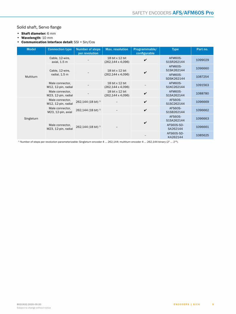
Solid shaft, Servo flange• Shaft diameter: 6 mm• Wavelength: 10 mm• Communication Interface detail: SSI + Sin/Cos
Model connection type number of steps per revolution
Max. resolution Programmable/configurable
Type Part no.
Multiturn
cable, 12-wire, axial, 1.5 m – 18 bit x 12 bit
(262,144 x 4,096) lafM60S-
S1SR262144 1099029
cable, 12-wire, radial, 1.5 m – 18 bit x 12 bit
(262,144 x 4,096) l
afM60S-S1SK262144 1096660
afM60S-SDSK262144 1087254
Male connector, M12, 12-pin, radial – 18 bit x 12 bit
(262,144 x 4,096) – afM60S-S1KC262144 1091563
Male connector, M23, 12-pin, radial – 18 bit x 12 bit
(262,144 x 4,096) lafM60S-
S1SA262144 1088780
Singleturn
Male connector, M12, 12-pin, radial 262,144 (18 bit) 1) – l
afS60S-S1SC262144 1096669
Male connector, M23, 12-pin, axial 262,144 (18 bit) 1) – l
afS60S-S1SB262144 1096662
Male connector, M23, 12-pin, radial 262,144 (18 bit) 1) –
l
afS60S-S1SA262144 1096663
afS60S-Sd-SA262144 1096661
– afS60S-Sd-KA262144 1085625
1) Number of steps per revolution parameterizable: Singleturn encoder 4 ... 262,144; multiturn encoder 4 ... 262,144 binary (22 ... 218).
ABCDEF
HIJKLMNOPQRST

E n c o d E r s | s I c K 8021932/2020-05-20Subject to change without notice
1 0
AFs/AFM60s Pro Safety encoderS
dimensional drawings (Dimensions in mm (inch))
Solid shaft, servo flange, radial plug connection M12 and M23
0.03 A
0.1 A
0.1 A Ø 0.05 B
Ø 0.1 C
AB
C
4 +0.1
(0.16)
3 (0.12)
10 ±0.3(0.39)
X
M12x1
14.5
(0.5
7)
7.75(0.31)
M23x1
26.1
(1.0
3)
13(0.51)
25°±2°
120° (3x)
X5:1
2 h9 (0.08)
Y10:1
Ø 42
±0.
05 (1
.65)
Ø 58
±0.
1 (2
.28)
Ø 51
.5 -0
.2 (2
.03)
Ø 50
f8 (1
.97)
Ø 6
f7 (0
.24)
10 +0.1
(0.39) 43.1(1.70)
Ø 60 (2.36)
10 ±0.3(0.39)
9.5(0.37)Ø
6 f7
(0.2
4)
5.7
(0.2
2)
0.8
(0.0
3)
2(0.08)
Y
A
5
3
1
2
4
General tolerances according to dIn ISo 2768-mk1 Measuring point working temperature (freely selectable, respectively circumferential at the cover shell, approx. 3 mm away from the flange)2 Measuring point vibration (respectively at the housing face. approx. 3 mm away from the cover edge)3 M3 / M4 (3x) (6-deep)4 Shaft with flat5 Key
ABCDEF
HIJKLMNOPQRST

E n c o d E r s | s I c K8021932/2020-05-20Subject to change without notice
1 1
Safety encoderS AFs/AFM60s Pro
Solid shaft, face mount flange, radial plug connection M12 and M239
(0.3
5)
40.1(1.58)10
(0.39)
Ø 0.05
19 ±0.3(0.75)
19 ±0.3(0.75)
Ø 10
f7 (0
.39)
Ø 10
f7 (0
.39)
Ø 36
f8 (1
.42)
3 h9(0.12)
1.2
(0.0
5)
3.5(0.14)
X2:1
X
Ø 6
0(2
.36)
Ø 4
8 ±0
.05
(1.8
9)
120° (3x)
B
0.03 A
0.1 AC
BA
14.
5(0
.57)
26.1
(1.0
3)
13(0.51)
7.75(0.31)
25°±2°
18(0.71)
A
M12x1
M23x1
Ø 0.1 C
1
2
35
4
General tolerances according to dIn ISo 2768-mk1 Measuring point working temperature (freely selectable, respectively circumferential at the cover shell, approx. 3 mm away from the flange)2 Measuring point vibration (respectively at the housing face. approx. 3 mm away from the cover edge)3 M3 / M4 (3x) (6-deep)4 Shaft with flat5 Key dIn 6885-a 3x3x6
ABCDEF
HIJKLMNOPQRST

E n c o d E r s | s I c K 8021932/2020-05-20Subject to change without notice
1 2
AFs/AFM60s Pro Safety encoderS
Solid shaft, servo flange, axial plug connection M12 and M23
Ø 0.05 B
4 +0.1
(0.16)
3 (0.12)
10 +0.1 (0.39)
57(2.24)
Ø 60 (2.36)
0.1 A
0.1 A
AB
C
0.03 A
Ø 0.1 C
Y12
(0.47)
Z
M12
x1
Z5:1
21.1 (0.83)
W
W3:1
Y3:1
Ø 42
±0.
05 (1
.65)
25°±2°
X
120°
(3x)
2 h9(0.08)
X10:1
10 ±0.3 (0.39)
Ø 58
±0.
1 (2
.28)
Ø 51
.5 -0
.2 (2
.03)
Ø 50
f8 (1
.97)
Ø 6
f7(0
.24)
10 ±0.3(0.39)
9.5(0.37)
Ø 6
f7 (0
.24)
5.7
(0.2
2)
0.8
(0.0
3)
2 (0.08)
A
1
2
M23
x 1
4
6
6
5
3
General tolerances according to dIn ISo 2768-mk1 Measuring point working temperature (freely selectable, respectively circumferential at the cover shell, approx. 3 mm away from the flange)2 Measuring point vibration (respectively at the housing face. approx. 3 mm away from the cover edge)3 M3 / M4 (3x) (6-deep)4 Shaft with flat5 Key dIn 6885-a 2x2x66 connector orientation
ABCDEF
HIJKLMNOPQRST

E n c o d E r s | s I c K8021932/2020-05-20Subject to change without notice
1 3
Safety encoderS AFs/AFM60s Pro
Solid shaft, face mount flange, axial plug connection M12 and M23
Ø 0.1 C
0.1 A
0.03 A
Ø 0.05 B
57(2.24)10
(0.39)
12(0.47)
X19 ±0.3
(0.75)
3.5 (0.14)
1.2
(0.0
5)
Ø 10
f7 (0
.39)
Ø 36
f8(1
.42)
M12
x1
C
BA
X5:1
3 h9(0.12)
Ø 4
8 ±0
.05
(1.8
9)
Ø 6
0 (2
.36)
120° (3x)
Y3:1
19 ±0.3(0.75)
18(0.71)Ø
10 f7
(0.3
9)
9 (0
.35)
21.1(0.83)
M23
x1
Y
A
25°±2°
1
2
4
6
6
53
General tolerances according to dIn ISo 2768-mk1 Measuring point working temperature (freely selectable, respectively circumferential at the cover shell, approx. 3 mm away from the flange)2 Measuring point vibration (respectively at the housing face. approx. 3 mm away from the cover edge)3 M3 / M4 (3x) (6-deep)4 Shaft with flat5 Key dIn 6885-a 3x3x66 connector orientation
ABCDEF
HIJKLMNOPQRST

E n c o d E r s | s I c K 8021932/2020-05-20Subject to change without notice
1 4
AFs/AFM60s Pro Safety encoderS
Solid shaft, servo flange, radial cable connection
Y10:1
X5:1
1
2
3
4
5
Ø 60 ± 0.5(2.36 ± 0.02)
Ø 42
± 0
.05
(1.6
5)
25° ± 2°12
0° (3
x)
Ø 0.1 C
Ø 0.05 B
0.1 A
0.1 A
0.03 A
B
C
AX
Y7.75(0.31)
SW 14
40.1(1.58)
10 + 0.1(0.39)
21 ±
2 (0
.83
± 0.
08)
10 ± 0.3(0.39 ± 0.01)
Ø 6
f7(0
.24)
Ø 50
f8
(1.9
7)
Ø 51
.5 - 0
.2 (2
.03 -0
.01)
Ø 58
± 0
.1 (2
.28)
(3) (0.12)
3 (0.12)
4 +0.1(0.16)
9.5(0.37)5.
7 (0
.22)
Ø 6
f7 (0
.24)
10 ± 0.3(0.39 ± 0.01)
(3) (
0.12
)
2 (0.08)
0.8
(0.0
3)
2 h9 (0.08)
General tolerances according to dIn ISo 2768-mk1 Measuring point working temperature (freely selectable, respectively circumferential at the cover shell, approx. 3 mm away from the flange)2 Measuring point vibration (respectively at the housing face. approx. 3 mm away from the cover edge)3 M3 / M4 (3x) (6-deep)4 Shaft with flat5 Key dIn 6885-a 2x2x6
ABCDEF
HIJKLMNOPQRST

E n c o d E r s | s I c K8021932/2020-05-20Subject to change without notice
1 5
Safety encoderS AFs/AFM60s Pro
Solid shaft, face mount flange, radial cable connection
1
2
63
45
40.1(1.58)10
(0.39)
7.75(0.31)
21 ±
2(0
.83
± 0.
02)
SW 14
Ø 60
± 0
.5(2
.36±
0.02
)
19 ± 0.3(0.75 ±0.01)
Ø 36
f8 (1
.42)
Ø 10
(0.3
9) f7
Ø 0.05 B
BX
C
A
(3)(0.12)
0.1 A
0.03 A
3 h9(0.12)
Ø 48
± 0
.05
(1.8
9)
Ø 0.1 C
120°
(3x)
25°± 2°
19 ± 0.3(0.75 ±0.01)
18(0.71)9
(0.3
5)
3.5(0.14)
1.2
(0.0
5)
X2:1
(3)
(0.1
2)
Ø 10
(0.3
9) f7
General tolerances according to dIn ISo 2768-mk1 Measuring point working temperature (freely selectable, respectively circumferential at the cover shell, approx. 3 mm away from the flange)2 Measuring point vibration (respectively at the housing face. approx. 3 mm away from the cover edge)3 M3 / M4 (3x) (6-deep)4 Shaft with flat5 Key dIn 6885-a 2x2x66 Key
ABCDEF
HIJKLMNOPQRST

E n c o d E r s | s I c K 8021932/2020-05-20Subject to change without notice
1 6
AFs/AFM60s Pro Safety encoderS
Solid shaft, servo flange, axial cable connection
1
2
3
4
5
Ø 60 ± 0.5(2.36 ± 0.02)
Ø 42
± 0
.5(1
.65)
120°
(3X)
SW 1
4
57 ± 0.5(2.24 ± 0.02)
10 +0.1 (0.39)
18.5 ± 2(0.73 ± 0.08)
Ø 50
f8 (1
.97)
Ø 51
.5 -0
.2 (2
.03
-0.0
1)
Ø 58
± 0
.1 (2
.28)
10 ± 0.3(0.39 ± 0.01)
Ø 6
f7(0
.24)
4 +0.1(0.16)
(3) (0.12)
3 (0.12)
(3) (
0.12
)
X10:1
Ø 0.1 C
Ø 0.05 B
0.1 A
0.1 A
0.03 A
AB
C
X
Y5:1
Y
2 (0.08)
0.8
(0.0
3)
10 ± 0.3(0.39 ± 0.01)
9.5(0.37)5.
7 (0
.22)
Ø 6
f7 (0
.24)
2 h9 (0.08)
General tolerances according to dIn ISo 2768-mk1 Measuring point working temperature (freely selectable, respectively circumferential at the cover shell, approx. 3 mm away from the flange)2 Measuring point vibration (respectively at the housing face. approx. 3 mm away from the cover edge)3 M3 / M4 (3x) (6-deep)4 Shaft with flat5 Key dIn 6885-a 2x2x6
ABCDEF
HIJKLMNOPQRST

E n c o d E r s | s I c K8021932/2020-05-20Subject to change without notice
1 7
Safety encoderS AFs/AFM60s Pro
Solid shaft, face mount flange, axial cable connection
12
5
34
57 ±0.5 (2.24 ±0.02)
10 (0.39)
SW 1
4
Ø 60
± 0
.5 (2
.36
±0.0
2)
Ø 36
(1.4
2) f8
Ø 10
(0.3
9) f7
Ø 0.05 B
B
C
A
(3) (0.12)
(3) (
0.12
)
0.1 A
0.03 A
3 h9(1.89)
Ø 48
± 0
.05
(1.8
9)
Ø 0.1 C
120°
(3x)
18.5 ± 2 (0.73 ±0.08)
19 ± 0.3(0.75 ±0.01)
18(0.71)
9 (0
.35)
Ø 10
(0.3
9) f7
3.5(0.14) 1.
2(0
.05)
19 ± 0.3(0.75 ±0.01)
General tolerances according to dIn ISo 2768-mk1 Measuring point working temperature (freely selectable, respectively circumferential at the cover shell, approx. 3 mm away from the flange)2 Measuring point vibration (respectively at the housing face. approx. 3 mm away from the cover edge)3 M3 / M4 (3x) (6-deep)4 Shaft with flat5 Key dIn 6885-a 3x3x6
ABCDEF
HIJKLMNOPQRST

E n c o d E r s | s I c K 8021932/2020-05-20Subject to change without notice
1 8
AFs/AFM60s Pro Safety encoderS
Blind hollow shaft, radial plug connection M12 and M23
Ø 60
(2.3
6)
Ø 32
.6(1
.28)
Ø 63 ±0.2 (2.48)
Ø 72 ±0.3 (2.83)
Ø X
F7
47 (1.85)3.2 +0.1
(0.12)
20(0
.79)
20°
X5:1
Ø X
j7
C - C2:1
C
C
min. 15 (0.59)
max. 40 (1.57)
45.5 (1.79)9.4 (0.37)
3.4(0.13)
2.5 (0.10)
M12x1 M23x1
7.75(0.31)14
.5(0
.57)
26.1
(1.0
3)
0.8
(0.0
3)
2 h9 (0.08)
max. 8.5 (0.33)min. 7.5 (0.30)
6(0.24)
A
max. 0,5
1
2
X
3
4
5
6
{General tolerances according to dIn ISo 2768-mk1 Measuring point working temperature (freely selectable, respectively circumferential at the cover shell, approx. 3 mm away from the flange)2 Measuring point vibration (respectively at the housing face. approx. 3 mm away from the cover edge)3 Attachment specifications4 Max. 0.4 at Ø 5/8”5 Key dIn 6885-a 2x2x66 Feather key groove
shaft diameter XF7 shaft diameter xj7
6 mm
Provided by customer
8 mm
3/8”
10 mm
12 mm
1/2″
14 mm
15 mm
5/8″
ABCDEF
HIJKLMNOPQRST

E n c o d E r s | s I c K8021932/2020-05-20Subject to change without notice
1 9
Safety encoderS AFs/AFM60s Pro
Blind hollow shaft, radial cable connection
max. 0,5
max. 8.5 (0.33)min. 7.5 (0.30)
6 (0.24)
1
2
6
5
3
4
9.4 (0.37) 2.5 (0.10)45.5 ± 0.5
(1.79 ±0.05)
(3)(0.12)
(3)
(0.1
2)
7.75 (0.31)
SW 14
3.4(0.13)
Ø 60
± 0
.5 (2
.36
±0.0
5)
Ø 32
.6(1
.28)
21 ±
2(0
.83
±0.0
8)
Ø X
F7
47 (1.85)
3.2 +0,1(0.13)
Ø 63 ± 0.2 (2.48 ±0.08)
72 ± 0.3 (2.38 ±0.01)
20 (0
.79)
20°X
X5:1
C
C
Ø X
J7
C–C2:1
2 h9(0.08)
0.8
(0.0
3)
min. 15 (0.59)
max. 40 (1.57 )
{1 Measuring point working temperature (freely selectable, respectively circumferential at the cover shell, approx. 3 mm away from the flange)2 Measuring point vibration (respectively at the housing face. approx. 3 mm away from the cover edge)3 Attachment specifications4 Max. 0.4 at Ø 5/8”5 Key dIn 6885-a 2x2x66 Feather key groove
shaft diameter XF7 shaft diameter xj7
6 mm
Provided by customer
8 mm
3/8”
10 mm
12 mm
1/2″
14 mm
15 mm
5/8″
ABCDEF
HIJKLMNOPQRST

E n c o d E r s | s I c K 8021932/2020-05-20Subject to change without notice
2 0
AFs/AFM60s Pro Safety encoderS
through hollow shaft, radial plug connection M12 and M23
max.0,5
43 (1.69)9.4 (0.37)
Ø 60
(2.3
6) Ø X
F7
3.4(0.13)
M12x1
7.75(0.31)
14.5
(0.5
7)
M23x1
26.1
(1.0
3)
13(0.51)
Ø 63 ±0.2 (2.48) Ø 72 ±0.3 (2.83)
47 (1.85)3.2 +0.1
(0.12)
20(0
.79)
20°
X5:10.
8 (0
.03)
2 h9 (0.08)
C - C2:1
Ø X
j7
C
C
max. 8.5 (0.33)min. 7.5 (0.30)
6(0.24)
min. 15 (0.59)
A
1
2
X
3
4
5
6
{General tolerances according to dIn ISo 2768-mk1 Measuring point working temperature (freely selectable, respectively circumferential at the cover shell, approx. 3 mm away from the flange)2 Measuring point vibration (respectively at the housing face. approx. 3 mm away from the cover edge)3 Attachment specifications4 Max. 0.4 at Ø 5/8”5 Key dIn 6885-a 2x2x66 Feather key groove
shaft diameter XF7 shaft diameter xj7
6 mm
Provided by customer
8 mm
3/8”
10 mm
12 mm
1/2″
14 mm
15 mm
5/8″
ABCDEF
HIJKLMNOPQRST

E n c o d E r s | s I c K8021932/2020-05-20Subject to change without notice
2 1
Safety encoderS AFs/AFM60s Pro
through hollow shaft, radial cable connection
max.0,5
1
2
6
5
3
4
9.4(0.37)
43 ± 0.5(1.69 ± 0.02)
(3)(0.12)
7.75(0.31)
SW 14
3.4(0.13)
Ø 60
± 0
.5(2
.36
± 0.
02) Ø
X F7
47(1.85)
3.2 +0.1(0.13)
Ø 63 ± 0.2(2.48 ± 0.01)
72 ± 0.3(2.83 ± 0.01)
20 (0.7
9)
20°X
X5:1
C
C
Ø X
J7
C–C2:1
2 h9(0.08)
0.8
(0.0
3)
min. 15(0.59)
(3)
(0.1
2)
max. 8.5 (0.33)min. 7.5 (0.30)
6(0.24)
21 ±
2(0
.83
± 0.
08){
General tolerances according to dIn ISo 2768-mk1 Measuring point working temperature (freely selectable, respectively circumferential at the cover shell, approx. 3 mm away from the flange)2 Measuring point vibration (respectively at the housing face. approx. 3 mm away from the cover edge)3 Attachment specifications4 Key dIn 6885-a 2x2x65 Max. 0.4 at Ø 5/8”6 Feather key groove
shaft diameter XF7 shaft diameter xj7
6 mm
Provided by customer
8 mm
3/8”
10 mm
12 mm
1/2″
14 mm
15 mm
5/8″
ABCDEF
HIJKLMNOPQRST

E n c o d E r s | s I c K 8021932/2020-05-20Subject to change without notice
2 2
AFs/AFM60s Pro Safety encoderS
PIn assignmentView of device plug M23 and M12 on the encoder
PIn (M23) PIn (M12) Wire colors (cable con-nection)
signal Explanation
1 5 red US Operating voltage
2 12 Blue Gnd Ground connection
3 11 yellow Clock + Interface signals
4 2 White Data + Interface signals
5 10 orange Set electronic adjustment
6 3 Brown data - Interface signals
7 4 Violet clock - Interface signals
8 9 Black - SIn Signal cable
9 1 orange-black CW/CCW (V/R̅) Sequence in direction of rotation
10 7 Green - coS Signal cable
11 6 Gray + COS Signal cable
12 8 Pink + SIN Signal cable
Screen
Screen connected to housing on encoder side. connected to ground on
control side.
Attachment specificationsMounting requirements for small servo clamp
3 x 120°
Ø 68 (2.68)
All dimensions in mm (inch)
Part no. 2029166
Mounting requirements for half-shell servo clamp
All dimensions in mm (inch)
4 x 90°
Ø 71 (2.80)
Part no. 2029165
ABCDEF
HIJKLMNOPQRST

E n c o d E r s | s I c K8021932/2020-05-20Subject to change without notice
2 3
Safety encoderS AFs/AFM60s Pro
accessoriesThe accessories are part of the safety-related function chain and must be assessed and validated accordingly by the user. This is not an integral part of the safety assessment carried out by SIcK SteGMann.
Mounting systems
flanges
flange plates
Figure Brief description Type Part no.
Flange adapter, adaptation of face mount flange with 36 mm centering hub to 50 mm servo flange, aluminum, including 3 flat head screws M4 x 10, Aluminum, including 3 countersunk screws M4 x 10
Bef-fa-036-050 2029160
Flange adapter, adaptation of face mount flange with 36 mm centering hub to 60 mm square mounting plate, aluminum, including 3 flat head screws M4 x 8, Aluminum, including 3 countersunk screws M4 x 8
Bef-fa-036-060rec 2029162
Flange adapter, adaptation of face mount flange with 36 mm centering hub to 58 mm square mounting plate with shock absorbers, aluminum, aluminum Bef-fa-036-060rSa 2029163
Flange adapter, adaptation of face mount flange with 36 mm centering hub to 63 mm square mounting plate, aluminum, including 3 flat head screws M4 x 10, Aluminum, including 3 countersunk screws M4 x 10
Bef-fa-036-063rec 2034225
Flange adapter, adaptation of face mount flange with 36 mm centering hub to 100 mm servo flange with 60 mm centering hub, aluminum, Aluminum Bef-fa-036-100 2029161
dimensional drawings g page 27
other mounting accessories
others
Brief description Type Part no.
1 M4x16 cylinder head screw and 1 2x2x6 feather key acc. to DIN 6885 Bef-MK-Se01 2073617
Servo clamps
Figure Brief description Type Part no.
Half-shell servo clamps (2 pcs.) for servo flanges with a 50 mm centering hub BEF-WG-SF050 2029165
Servo clamps, large, for servo flanges (clamps, eccentric fastener), 3 pcs., without mounting material, without mounting hardware BEF-WK-SF 2029166
dimensional drawings g page 28
Shaft adaptation
Shaft couplings
Figure Brief description Type Part no.
Bellows coupling, shaft diameter 6 mm / 6 mm, maximum shaft offset: radial ± 0.25 mm, axial ± 0.4 mm, angular +/- 4°; max. speed 10,000 rpm, –30 °C to +120 °C, max. torque 80 Ncm; material: stainless steel bellows, aluminum hub, for use with feather key
KUP-0606-BP 2075379
Bellows coupling, shaft diameter 6 mm / 6 mm, maximum shaft offset: radial ± 0.25 mm, axial ± 0.4 mm, angular ± 4°; max. speed 10,000 rpm, –30 °C ... +120° C, max. torque 80 Ncm; material: stainless steel bellows, fixed with two setscrews each
KUP-0606-BS 2075378
ABCDEF
HIJKLMNOPQRST

E n c o d E r s | s I c K 8021932/2020-05-20Subject to change without notice
2 4
AFs/AFM60s Pro Safety encoderS
Figure Brief description Type Part no.
Bellows coupling, shaft diameter 6 mm / 10 mm, maximum shaft offset: radial ± 0.25 mm, axial ± 0.4 mm, angular +/- 4°; max. speed 10,000 rpm, –30 °C to +120 °C, max. torque 80 Ncm; material: stainless steel bellows, aluminum hub, for use with feather key
KUP-0610-BP 2075375
Bellows coupling, shaft diameter 6 mm / 10 mm, bellows coupling, shaft diameter 6 mm / 6 mm, maximum shaft offset: radial ± 0.25 mm, axial ± 0.4 mm, angular ± 4°; max. speed 10,000 rpm, –30 °C ... +120° C, max. torque 80 Ncm; material: stainless steel bellows, fixed with two setscrews each
KUP-0610-BS 2075377
Bellows coupling, shaft diameter 10 mm / 10 mm, maximum shaft offset: radial ± 0.25 mm, axial ± 0.4 mm, angular +/- 4°; max. speed 10,000 rpm, –30 °C to +120 °C, max. torque 80 Ncm; material: stainless steel bellows, aluminum hub, for use with feather key
KUP-1010-BP 2075373
Bellows coupling, shaft diameter 10 mm / 10 mm, maximum shaft offset: radial ± 0.25 mm, axial ± 0.4 mm, angular ± 4°; max. speed 10,000 rpm, –30° ... +120° C, max. torque 80 Ncm; material: stainless steel bellows, fixed with two setscrews each
KUP-1010-BS 2075376
dimensional drawings g page 28
connection systems
Plug connectors and cables
Cables (ready to assemble)
Figure Brief description Type Part no.
Head a: cableHead B: flying leadsCable: SSI, TTL, HTL, PUR, halogen-free, shielded, 4 x 2 x 0.25 mm² + 2 x 0.5 mm² + 2 x 0.14 mm², 7.8 mm, UV and saltwater-resistant
LTG-2612-MW 6028516
connecting cables
Figure Brief description Length of cable Type Part no.
Head a: female connector, M12, 12-pin, straight, a-codedHead B: flying leadsCable: SSI, PUR, halogen-free, shield-ed, 12 x 0.14 mm², 8.5 mm
2 m doL-1212-G02Mac1 6053273
5 m doL-1212-G05Mac1 6053274
10 m doL-1212-G10Mac1 6053275
20 m doL-1212-G20Mac1 6053276
Head a: female connector, M12, 12-pin, angled, a-codedHead B: flying leadsCable: SSI, PUR, halogen-free, shield-ed, 12 x 0.14 mm², 8.5 mm
2 m doL-1212-W02MAC1 6039824
5 m doL-1212-W05MAC1 6039825
10 m doL-1212-W10MAC1 6039826
20 m doL-1212-W20MAC1 6039827
ABCDEF
HIJKLMNOPQRST

E n c o d E r s | s I c K8021932/2020-05-20Subject to change without notice
2 5
Safety encoderS AFs/AFM60s Pro
Figure Brief description Length of cable Type Part no.
Head a: female connector, M23, 12-pin, straightHead B: flying leadscable: shielded, 7.8 mm
3 m doL-2312-G03M-Md2 2062300
5 m doL-2312-G05M-Md2 2062301
Head a: female connector, M23, 12-pin, straightHead B: flying leadscable: shielded, Ø 6.8 mm
5 m doL-2312-G05MXd2 2095662
Head a: female connector, M23, 12-pin, straightHead B: flying leadscable: shielded, 7.8 mm
10 m doL-2312-G10M-Md2 2062302
Head a: female connector, M23, 12-pin, straightHead B: flying leadscable: unshielded, 7.8 mm
1.5 m doL-2312-G1M-5Md2 2062284
Head a: female connector, M23, 12-pin, straightHead B: flying leadscable: shielded, Ø 6.8 mm
1.5 m doL-2312-G1M-5MXd2 2097360
Head a: female connector, M23, 12-pin, straightHead B: flying leadscable: shielded, 7.8 mm
20 m doL-2312-G20M-Md2 2062303
30 m doL-2312-G30M-Md2 2062304
dimensional drawings g page 29
connection cables
Figure Brief description Length of cable Type Part no.
Head a: male connector, Micro d-Sub, 15-pin, angledHead B: female connector, M12, 12-pin, straightcable: shieldeddetails: for connecting the fX3-Moc motion control modules to an encoder
10 m connection cable 2094436
1 m connection cable 2094372
3 m connection cable 2094434
5 m connection cable 2094435
Head a: female connector, M12, 12-pin, straightHead B: male connector, d-Sub, 9-pin, straightCable: SSI + incremental, SSI + Sin/cos, Incremental, shielded, 12 x 0.14 mm², 8.5 mm details: Programming adapter cable for programming tool PGt-10-Pro and PGt-08-S
0.5 m dSL-2d12-G0M5AC4 2088790
Head a: female connector, M23, 12-pin, straightHead B: male connector, d-Sub, 9-pin, straightCable: SSI, PUR, halogen-free, shield-ed, 4 x 2 x 0.15 mm² details: Programming adapter cable for programming tool PGt-10-Pro and PGt-08-S
0.5 m dSL-3d08-G0M5AC4 2059270
field-attachable connectors
Figure Brief description Type Part no.
Head a: female connector, M23, 12-pin, straightHead B: -cable: HIPerface®, SSI, Incremental, shielded
doS-2312-G 6027538
doS-2312-G02 2077057
ABCDEF
HIJKLMNOPQRST

E n c o d E r s | s I c K 8021932/2020-05-20Subject to change without notice
2 6
AFs/AFM60s Pro Safety encoderS
Figure Brief description Type Part no.
Head a: female connector, M23, 12-pin, angledHead B: -cable: HIPerface®, SSI, Incremental, shielded
DOS-2312-W01 2072580
Head a: male connector, M23, 12-pin, straightHead B: -cable: HIPerface®, SSI, Incremental, RS-422, shielded
Ste-2312-G 6027537
Head a: male connector, M23, 12-pin, straightHead B: -cable: HIPerface®, SSI, Incremental, shielded
Ste-2312-G01 2077273
Ste-2312-GX 6028548
dimensional drawings g page 29
other connectors and cables
Figure short description Type Part no.
System plug: Voltage supply of the Flexi Soft system and storage of system configura-tion (without EFI-compatible devices) fX3-MPL000001 1043700
System plug: Voltage supply of the Flexi Soft system, storage of system configuration (including EFI-compatible devices), and automatic configuration of connected EFI-com-patible safety sensors (automatic configuration recovery)
fX3-MPL100001 1047162
further accessories
Programming and configuration tools
Figure Brief description Type Part no.
USB programming unit, for programmable SICK encoders AFS60, AFM60, DFS60, VFS60, DFV60 and wire draw encoders with programmable encoders PGt-08-S 1036616
Safety controllers
flexi Soft
Figure Further accessories Type Part no.
Safety controllers, flexi Soft
FX3-CPU000000 1043783
FX3-CPU130002 1043784
FX3-CPU230002 1058999
FX3-CPU320002 1059305
fX3-Moc000000 1062344
dimensional drawings g page 33
ABCDEF
HIJKLMNOPQRST

E n c o d E r s | s I c K8021932/2020-05-20Subject to change without notice
2 7
Safety encoderS AFs/AFM60s Pro
dimensional drawings for accessories (Dimensions in mm (inch))
flangesBef-fa-036-050
10 +0.1 (0.39) 3 +0.1 (0.12) 4 –0.1 (0.16)
Ø 51
(2.0
0)
Ø 36
H8
(1.4
2)
0.3 +0.1 (0.01)2.3 (0.09)
3 x
90°
58 (2.28)
3 x M4 Pos.4,Pos.5,Pos.6
41
0
5
26
3
50 18 (1.97)
3 x 4.1 +0.1
(0.16)8 +0.1
(0.31)
Rz 6.3
A0.02 A
0.05 A
Bef-fa-036-060rec
36 H8 (1.42)4 xR4
4 x
4.5
(0.1
8)
48 (1.89)58 (2.28)
48 (1
.89)
58 (2
.28)
4 (0.16)
Bef-fa-036-060rSa
10 (0.39)
10(0.39)
4 (0.39)
4 x springwasher
4 x hexagonalnut (secure withLoctite 241)
4 x
Ø 10
±0.
3 (0
.39)
4 x
M4
2.8
(0.1
1) d
eep
48 ±0.1 (1.89)
36 H8 (1.42)
58 ±0.2 (2.28)
Bef-fa-036-063rec
A
A
A–A
28°
52.4
±0.
1 (2
.06)
3 x
120°
63 ±0.2 (2.48)
Ø 48
±0.
1 (1
.89)
Ø 36
H8
(1.4
2)
5 (0.20)
3 x
Ø 8.
6 ±0
.2 (0
.34)
45°
4 x
Ø 5.
5(0
.22)
3 x
Ø 4.
3 (0
.17)
H12
Bef-fa-036-100
90°
120° (3x)
Ø 8.
6 (3
x)(0
.34)
Ø 36
(1.4
2)
Ø 48
±0.
1(1
.89)
Ø 70
±0.
1 (2
.76)
Ø 92
±0.
1 (3
.62)
Ø 10
0 ±0
.1 (3
.94)
Ø 60
f8 (2
.36)
M 6
(3x)
Ø 4.
3 (3
x)(0
.17)
10(0.39)
3.1(0.12)
3(0.12)
ABCDEF
HIJKLMNOPQRST

E n c o d E r s | s I c K 8021932/2020-05-20Subject to change without notice
2 8
AFs/AFM60s Pro Safety encoderS
other mounting accessoriesBEF-WG-SF050
4 x
90°
A
A
45°
1 (0.04)
71 ±
0.02
(2.8
0)
81 (3
.19)
5.6 –0.1 (0.22)
2.8 –0.05 (0.11)
Ø 52
.2 (2
.06)
Ø 58
.2 (2
.29)
4 x
Ø 4
.3 ±
0.1
(0.1
7)
a
4 x
Ø 8
(0.3
1)
4.6(0.18)
A-A
BEF-WK-SF
11 (0
.43)
14 (0.55)
Ø 7.
4 –0
.1(0
.29)
1 +0.1
(0.04)
Ø 4.
2 (0
.17)
Ø 7–
0.1
(0.2
8)
2.8 –0.1 (0.11)
5.5 –0.1 (0.22)
Shaft adaptationKUP-0606-BP
Ø 21 ±0.1(0.83)
9 (0.35)
29 ±1 (1.14)
Ø 6
H8
(0.2
4) Ø 6
H8
(0.2
4)
A-A (2:1)
A
A
2 JS9 (+0,012 - 0,012) (2x)
4 +0
.1
- 0
(2x)
(0.1
6)
(0.08 JS9)
KUP-xxxx-BS
29 ±1 (1.14)
Ø 20
(0.7
9)
Grub screwsM4x6 DIN916 3.2 (0.13)
120°
Ø d1
H8
Ø d2
H8
KUP-0610-BP
A-A (2:1) A
A29 ±1 (1.14)
9 (0.35)
Ø 10
H8
(0.3
9) Ø 6
H8
(0.2
4)
3 JS9 (+0.012 - 0.012)
(0.12 JS9)
(0.08 JS9)
2 JS9 (+0.012 - 0.012)
Ø 21 ±0.1(0.83)6.
4 +0
.1
- 0
(0.2
5)
(0.1
6)
4 +0
.1
- 0
KUP-1010-BP
Ø 21 ±0.1(0.83)
29 ±1 (1.14)
9 (0.35)
Ø 10
H8
(0.3
9)
Ø 10
H8
(0.3
9)
A-A (2:1)A
A
3 JS9 (+0.012 - 0.012) (2x) (0.12 JS9)
6.4
+0.1
- 0
(2
x) (0
.25)
Plug connectors and cablesdoL-1212-GxxMac1
45 (1.77)
14.8
(0.5
8)
14.1
(0.5
6)
3 brn 11 yel
4 vio
5 red
6 gra
7 grn8 pnk
12 blu9 blk
1 org /blk
10 org2 wht
DOL-1212-WxxMAC1
14.8(0.58)
30 (1
.18)
36.6 (1.44)
14.1
(0.5
6)
2 3 11 4
5
6 7 8
9
10
12 blu
View of the female connector
ABCDEF
HIJKLMNOPQRST

E n c o d E r s | s I c K8021932/2020-05-20Subject to change without notice
2 9
Safety encoderS AFs/AFM60s Pro
doL-2312-G03MMd2
1 red2 Blue3 yellow4 White5 orange6 Brown7 Purple8 Black9 orange/blackß Greenà Grayá Pink
doL-2312-G05MMd2
1 red2 Blue3 yellow4 White5 orange6 Brown7 Purple8 Black9 orange/blackß Greenà Grayá Pink
doL-2312-G05MXd2
1
10(0.39)
24 (0.94)
40 ±2 (1.57 ±0.08)
5000 (196.85)
64.7 (2.55)
27.2
(1.0
7)
1 Stripped
doL-2312-G10MMd2
1 red2 Blue3 yellow4 White5 orange6 Brown7 Purple8 Black9 orange/blackß Greenà Grayá Pink
doL-2312-G1M5Md2
1 red2 Blue3 yellow4 White5 orange6 Brown7 Purple8 Black9 orange/blackß Greenà Grayá Pink
ABCDEF
HIJKLMNOPQRST

E n c o d E r s | s I c K 8021932/2020-05-20Subject to change without notice
3 0
AFs/AFM60s Pro Safety encoderS
doL-2312-G20MMd2
1 red2 Blue3 yellow4 White5 orange6 Brown7 Purple8 Black9 orange/blackß Greenà Grayá Pink
doL-2312-G30MMd2
1 red2 Blue3 yellow4 White5 orange6 Brown7 Purple8 Black9 orange/blackß Greenà Grayá Pink
doS-2312-G
1 Blue2 White3 yellow4 Gray5 Green6 Pink7 Black8 red9 orangeß Brownà Purpleá orange/black
doS-2312-G02
1
210127
8 9
11 365 4
64.7(2.55)
Ø 27
.2(1
.02)
Plug insert 12 pin
(plug-in face)
SW 24SW 24
ABCDEF
HIJKLMNOPQRST

E n c o d E r s | s I c K8021932/2020-05-20Subject to change without notice
3 1
Safety encoderS AFs/AFM60s Pro
DOS-2312-W01
E 1
23
456
7
8 9
10
11
12
Contact arrangementMating view
Main dimensionsPlug
81 (3.19)
58 (2
.28)
SW 25
Ø 26 (1.02)
Rotating area tothe left 124°
Rotating area tothe right 200°
SW 27
Ø 27
.2 (1
.07)
Ste-2312-G
Ste-2312-G01
8
712102
1 9
11 634 5
66.7(2.63)
Ø 26
.5(1
.04) M
23 x
1
Pin insert 12 pin
(plug-in face)
SW 24SW 24
ABCDEF
HIJKLMNOPQRST

E n c o d E r s | s I c K 8021932/2020-05-20Subject to change without notice
3 2
AFs/AFM60s Pro Safety encoderS
Ste-2312-GX
110
2
3
411 5
6
12
7
89
1 x
M23
Max. 9 (0.35) 4
57 (2.24)
31 (1.22)
3.5(0.14)
1.5
x M
25
1
2
3
528 (1.10)
P
1 fixed stop position2 Vibration protection3 Fixing nut SW304 Max. wall thickness5 SW23
flexi SoftFX3-CPU0
96.5(3.80)
93.3(3.67)
114.
3(4
.50)
19.5
(0.7
7)75
.3(2
.97)
120.
6(4
.75)
15.4(0.61)
33.1(1.30)
58(2.28)
78(3.07)
109
(4.2
9)
93.7
(3.6
9)20 (0.7
9)22
.5(0
.89)
8.8
(0.3
4)
8.5(0.33)
20 (0.7
9)
1 approximate connector range
FX3-CPU1, FX3-CPU2
8.5(0.33)
96.5(3.80)
93.3(3.67)
19.5
(0.7
7)20 (0.7
9)
14.8
(0.5
8)
15.4(0.61)
33.1(1.30)
58(2.28)
78(3.07)
5.1(0.20)
75.3
(2.9
6)93
.7(3
.69)
109
(4.2
9)114.
3(4
.50)
75.3
(2.9
7)
120.
6(4
.75)
20 (0.7
9)22
.5(0
.89)
8.8
(0.3
4)
1 approximate connector range
ABCDEF
HIJKLMNOPQRST
E n c o d E r s | s I c K8021932/2020-05-20Subject to change without notice
3 3
Safety encoderS AFs/AFM60s Pro
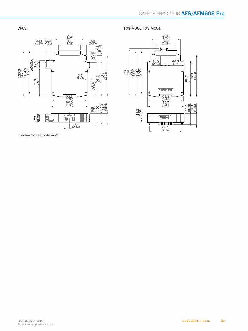
CPU3
8.5(0.33)
5.1(0.20)
96.5(3.80)
93.3(3.67)
75.2
(2.9
6)93
.7(3
.69) 10
9(4
.29)
114.
3(4
.50)
19.5
(0.7
7)75
.3(2
.97)
20 (0.7
9)
20 (0.7
9)22
.5(0
.89)
14.8
(0.5
8)14
.8(0
.58)
120.
6(4
.75)
15.4(0.61)
33.1(1.30)
58(2.28)
5.1(0.20)
78(3.07)
8.8
(0.3
4)
1 approximate connector range
fX3-Moc0, fX3-Moc1
86.5(3.41)
29.1
(1.1
5)
22.5
(0.8
9)
13.3
(0.5
2)
109
(4.2
9)
93.7
(3.6
9)
96.5(3.80)
93.3(3.67)
114.
3(4
.50)
120.
6(4
.75)
126
(4.9
6)
18.2(0.71)
44.3(1.74)
58(2.28)
78(3.07)
ABCDEF
HIJKLMNOPQRST

E n c o d E r s | s I c K 8021932/2020-05-203 4Subject to change without notice
noteS
ABCDEF
HIJKLMNOPQRST

SERVICES FOR MACHINES AND PLANTS: SICK LifeTime ServicesOur comprehensive and versatile LifeTime Services are the perfect addition to the comprehensive range of products from SICK. The services range from product-independent consulting to traditional product services.
Training and educationPractical, focused, and professional
Upgrade and retrofitsEasy, safe, and economical
Consulting and designSafe and professional
Verification and optimizationSafe and regularly inspected
Product and system supportReliable, fast, and on-site
SERVICES
REGISTER AT WWW.SICK.COM TO TAKE ADVANTAGE OF OUR FOLLOWING SERVICES FOR YOU
Access information on net prices and individual discounts.
Easily order online and track your delivery.
Check your history of all your orders and quotes.
Create, save, and share as many wish lists as you want.
Use the direct order to quickly order a big amount of products.
Check the status of your orders and quotes and get information on status changes by e-mail.
Save time by using past orders.
Easily export orders and quotes, suited to your systems.
m
m
m
m
m
m
m
m
3 58021932/2020-05-20Subject to change without notice
E n c o d E r s | s I c K

SICK AG | Waldkirch | Germany | www.sick.com
SICK AT A GLANCESICK is a leading manufacturer of intelligent sensors and sensor solutions for industrial applications. With more than 9,700 employees and over 50 subsidiaries and equity investments as well as numerous agencies worldwide, SICK is always close to its customers. A unique range of products and services creates the perfect basis for controlling processes securely and efficiently, protecting individuals from accidents, and preventing damage to the environment.
SICK has extensive experience in various industries and understands their processes and requirements. With intelligent sensors, SICK delivers exactly what the customers need. In application centers in Europe, Asia, and North America, system solutions are tested and optimized in accordance with customer specifica-tions. All this makes SICK a reliable supplier and development partner.
Comprehensive services round out the offering: SICK LifeTime Services provide support throughout the machine life cycle and ensure safety and productivity.
That is “Sensor Intelligence.”
Worldwide presence:
Australia, Austria, Belgium, Brazil, Canada, Chile, China, Czech Republic, Denmark, Finland, France, Germany, Great Britain, Hungary, Hong Kong, India, Israel, Italy, Japan, Malaysia, Mexico, Netherlands, New Zealand, Norway, Poland, Romania, Russia, Singapore, Slovakia, Slovenia, South Africa, South Korea, Spain, Sweden, Switzerland, Taiwan, Thailand, Turkey, United Arab Emirates, USA, Vietnam.
Detailed addresses and further locations - www.sick.com
8021
932/
2020
-05
-20
∙ JJ_
07 ∙
Pre
USm
od e
n49