africa product guide global brochure final proof v6 fix feb... · model emissions compliance...
TRANSCRIPT

Africa Product Guide
2 3
Definitions 4
Diesel Generator Sets 10
Gas Generator Sets 18
Enclosures 24
Rental Power 30
PowerCommand® Generator Set Controls 34
PowerCommand® Automatic Transfer Switches 40
PowerCommand® Digital Paralleling Systems 44
PowerCommand® Remote Monitoring Systems 50
PowerCommand® InPower™ - Service & Maintenance 54
Contents

4 5
Emergency Standby Power (ESP):
Applicable for supplying power to varying electrical load for the duration of power interruption of a reliable utility source. Emergency Standby Power (ESP) is in accordance with ISO 8528. Fuel stop power in accordance with ISO 3046, AS 2789, DIN 6271 and BS 5514.
Prime Power (PRP):
Applicable for supplying power to varying electrical load for unlimited hours. Prime Power (PRP) is in accordance with ISO 8528. Ten percent overload capability is available in accordance with ISO 3046, AS 2789, DIN 6271 and BS 5514.
Limited-Time Running Power (LTP):
Applicable for supplying power to a constant electrical load for limited hours. Limited Time Running Power (LTP) is in accordance with ISO 8528.
Base Load (Continuous) Power (COP):
Applicable for supplying power continuously to a constant electrical load for unlimited hours. Continuous Power (COP) is in accordance with ISO 8528, ISO 3046, AS 2789, DIN 6271 and BS 5514.
Data Center Continuous (DCC):
Applicable for supplying power continuously to a constant or varying electrical load for unlimited hours in a data center application.
Definitions

6 7
Global strength,local partnership
7517

8 9
Low Emission Technologies
Diesel Generator Sets
We are committed to meeting or exceedingclean air standards worldwide.
Integrated design and manufacturing combine to give you unequalled reliability, power quality, rated performance and efficient operation,

10 1150 Hz
Diesel Generator Sets

12 13
Diesel Diesel
Business Location Netcare St. Augustine’s Hospital is KwaZulu-Natal’s largest private hospi-tal and the second-largest care center in the Netcare Group.
Operational NeedThe risk of mains power failure represented a major hazard for St. Augustine’s, the 418-bed hospital, particularly for dangers posed to patients in operating theatres and high-care units. The hospital had previously been reliant upon small generators for essential services only. When hospital administrators sought comprehensive emergency power protection for the entire establishment, they turned to the experts at Cummins Power Generation. Primary Choice Factors Cummins recommended two new diesel-powered generator sets capable of synchronizing and producing the full power load within 15 seconds after a mains power failure. In the unlikely event of generator set failure, the system is designed to provide uninterrupted power on pre-determined essential power loads (such as operating rooms or intensive care units) with its remaining generator set. The complete operation is controlled by Cummins’ MC150 master control that can be programmed to provide pre-determined load share, load shed and sequential load demand protocols. Cummins’ reputation for an excellent national support network and superior technical services was a primary driver in the hospital’s selection of the new emergency standby power system.
ResultTwo C1400 D5 generator sets provide a reliable source of standby power that keeps the hospital fully operational in the event of a blackout. An MC150 master control manages the operation of the entire system and is programmed to provide pre-determined load share/shed and sequential load demand protocols.
The largest capital project in the history of Madagascar, the Ambatovy project, has purchased 30 Cummins Power Generation generator sets to help meet its requirement for prime power. The combined mine and processing project has the potential to be a huge boost to the country’s economy. When it began to face problems with its prime power provision, it was vital to find a solution.
Cummins South Africa, Power Generation was chosen for the work and has provided 30 Cummins Power Generation C1250 D2R generator sets using KTA50-G3 engines and STAMFORD P7 alternators. The total order, valued at US$15 million, was installed at the site and began providing the much needed extra power by late November 2011.
The customer initially considered renting the required equipment, but saw the value in purchasing the KTA50-G3 powered, rental-spec generator sets thanks to their durability and reputation for operating in harsh conditions. Cummins support, service and its commitment to delivering and setting up in a short time frame were also key factors in the decision. More than 200 public hearings were held to examine the project’s social and environmental issues, which led to the adoption of environmental conservation models based on World Bank guidelines. The project is contributing greatly to the local economy. Around 12,000 workers were hired directly and indirectly during the construction phase. A local development programme provides a human resources registration centre with occupational and technical training programmes for small to medium sized local companies.
Netcare St. Augustine’s HospitalDurban, South Africa
Mission CriticalPrime Power
The Ambatovy ProjectMadagascar super-mine project calls in Cummins

14 15
Diesel
Business Location Ethio Telecom (ET) is the only telecom operator in Ethiopia, whose primary objective is to improve the coverage and quality of their network across the country.
Operational Need Ethiopia is the second most populous country in Africa with a closed economy and letter of credits heavily controlled by the government. With only one state run telecom operator, poor network coverage and the government’s priority to improve the cellular network to aid in economic growth, ET launched their telecom expansion program to introduce new base transceiver station technology, improve coverage and increase network uptime. All the towers needed to be backed up by generators to ensure increased network uptime when the grid fails.
Primary Choice Factors Quality, reputation and strong support in country. ET also wanted to retain their old proven technology of using air cooled generators. However, Cummins was successful in lobbying ET against air cooled generators and to adopt water cooled generators.
Result Cummins competed against all major international generator competitors and was successfully chosen to supply water cooled generators for a period of two years. Thus far we have supplied ~800 generators to ET via Huawei, the biggest Telecom Equipment provider in the world.
Commercial & Industrial
EthioTelecom / HuaweiEthiopia
Notes:

16 17
50 Hz RANGE
• Standard • Option - Not Available
Diesel
Model Name
Standby Rating
Prime Rating Engine
ModelEmissions
ComplianceStandard
AlternatorStandard Control
Sound Enclosure
kVA kWe kVA kWe
C17D5 16.5 13 15 12 X2.5-G2 - PI044G PS0500 •
C22D5 22 17 20 16 X2.5-G2 - PI144D PS0500 •
C28D5 27.5 22 25 20 X2.5-G2 - PI144F PS0500 •
C33D5 33 26 30 24 X3.3-G1 - PI144G PC 1.1 •
C38D5 38 30 35 28 X3.3-G1 - PI144H PC 1.1 •
C44D5 44 35 40 32 S3.8-G4 - UCI224C PS0500 •
C55D5 55 44 50 40 S3.8-G6 - UCI224D PS0500 •
C66D5 66 52 60 48 S3.8-G7 - UCI224F PS0500 •
C90D5 90 72 82 65 6BTA5.9-G5 - UCI224G PC 1.2 •
C110D5 110 88 100 80 6BTA5.9-G5 - UCI274C PC 1.2 •
C150D5 150 120 136 109 6BTAA5.9-G6 - UCI274E PC 1.2 •
C170D5 170 136 155 124 6BTAA5.9-G7 - UCI274F PC 1.2 •
C175D5e 175 140 158 126 QSB7-G5 EU IIIA UCI274F PC 1.2 •
C200D5e 200 160 182 146 QSB7-G5 EU IIIA UCI274H PC 1.2 •
C220D5e 220 176 200 160 QSB7-G5 EU IIIA UCI274H PC 1.2 •
C250D5e 250 200 225 180 QSL9-G7 EU IIIA UCDI274K PC 1.2 •
C275D5 275 220 250 200 QSL9-G5 TA Luft 4g UCDI274K PC 1.2 •
C275D5e 275 220 250 200 QSL9-G7 EU IIIA HCI4D PC 1.2 •
C300D5 300 240 275 220 QSL9-G5 TA Luft 4g HCI4D PC 1.2 •
C300D5e 300 240 275 220 QSL9-G7 EU IIIA HCI4D PC 1.2 •
C330D5 330 264 300 240 QSL9-G5 TA Luft 4g HCI4D PC 1.2 •
C330D5e 330 264 300 240 QSL9-G7 EU IIIA HCI4D PC 1.2 •
Diesel
• Standard • Option - Not Available
50 Hz RANGE
Model Name
Standby Rating
Prime Rating
Engine Model
Emissions Compliance
Standard Alternator
Standard Control
Sound Enclosure
kVA kWe kVA kWe
C350D5 350 280 320 256 NT855-G6 - HCI4E PCC 2100 •
C400D5 400 320 360 288 NTA855-G4 - HCI4F PCC 2100 •
C400D5e 400 320 364 291 QSX15-G8 EU Stage II HCI4F PC 2.2 •
C440D5 440 352 400 320 NTA855-G7 - HCI5C PCC 2100 •
C450D5e 450 360 409 327 QSX15-G8 EU Stage II HCI5C PC 2.2 •
C450D5eB 450 360 409 327 QSZ13-G7 EU Stage IIIA HCI5C PC 2.2 •
C500D5 500 400 455 364 QSZ13-G5 EU Stage II HCI5C PC 2.2 •
C500D5e 500 400 455 364 QSX15-G8 EU Stage II HCI5C PC 2.2 •
C550D5e 550 440 500 400 QSX15-G8 EU Stage II HCI5D PC 2.2 •
C700D5 706 565 640 512 VTA28-G5 - HCI5F PC 3.3 ISO20
C825D5 825 660 750 600 QSK23-G3 - HCI6G PCC 2100 -
C825D5A 825 660 750 600 VTA28-G6 - HCI6G PC 3.3 ISO20
C900D5 900 720 820 656 QSK23-G3 - HCI6H PCC 2100 -
C1000D5B 1000 800 900 720 KTA38-G14 - HCI6K PC 3.3 HC40
C1000D5 1041 833 939 751.2 QST30-G3 - HCI6J PC 3.3 ISO20

18 19
50 Hz RANGE
Diesel
Model Name
Standby Rating
Prime Rating
DCC Rating
Continuous Rating
Engine Model
Emis-sions
Compli-ance
Standard Alternator
Stan-dard Con-trol
Sound Enclo-sure
kVA kWe kVA kWe kVA kWe kVA kWe
C1100D5 1110 888 1000 800 - - - - QST30-G4 - HCI6K PC 3.3 -
C1100D5B 1132 906 1029 823 - - - - KTA38-G14 - HCI6K PC 3.3 HC40
C1400D5 1400 1120 1250 1000 1250 1000 - - KTA50-G3 - PI734B PC 3.3 -
C1675D5 1675 1340 1400 1120 1400 1120 - - KTA50-G8 - PI734D PC 3.3 -
C1675D5A 1675 1340 1500 1200 1500 1200 - - KTA50-GS8 - PI734D PC 3.3 -
C1760D5e 1760 1408 1600 1280 1600 1280 - - QSK60-GS3 TA Luft 2g PI734D PCC
3201 -
C2000D5e 2000 1600 1825 1460 1825 1460 - - QSK60-GS3 TA Luft 2g PI734F PCC
3201 -
C2000D5 2063 1650 1875 1500 1875 1500 - - QSK60-G3 - PI734F PCC
3201 -
C2250D5 2250 1800 2000 1600 2000 1600 - - QSK60-G4 - PI734G PCC
3201 -
C2500D5A 2500 2000 2250 1800 2250 1800 - - QSK60-G8 TA Luft 4g LVSI804S PCC
3201 -
C2750D5 2750 2200 2500 2000 2500 2000 2250 1800 QSK78-G9 TA Luft 4g LVS1804S PC 3.3 -
C2750D5e 2750 2200 2500 2000 2500 2000 2000 1600
QSK78-G15 /
QSK78-G16
EPA Tier 2 / 2GTAL LVS1804S PC 3.3 -
C3000D5 3000 2400 2750 2200 2750 2200 2475 1980 QSK78-G9 TA Luft 4g LVS1804S PC 3.3 -
C3000D5e 3000 2400 2750 2200 2750 2200 2100 1680
QSK78-G15 /
QSK78-G16
EPA Tier 2 / 2GTAL LVS1804S PC 3.3 -
50 Hz RANGE
Model Name
Standby Rating
Prime Rating
DCC Rating
Continuous Rating
Engine Model
Emis-sions
Compli-ance
Standard Alternator
Stan-dard Con-trol
Sound Enclo-sure
kVA kWe kVA kWe kVA kWe kVA kWe
C3500D5 3500 2800 3125 2500 3125 2500 2750 2200 QSK95-G4 - LVSI804W PC
3.3 -
C3500D5e 3500 2800 3125 2500 3125 2500 2750 2200QSK95-G5/G10
TA Luft 2g / EPA
Tier 2
LVSI804W PC 3.3 -
C3750D5 3750 3000 3350 2680 3350 2680 3000 2400 QSK95-G4 - LVSI804X PC
3.3 -
C3750D5e 3750 3000 3350 2680 3350 2680 3000 2400 QSK95-G10
EPA Tier 2 LVSI804X PC
3.3 -
Diesel
Model Name
Standby Rating
Prime Rating Engine
ModelEmissions
ComplianceStandard
AlternatorStandard Control
Sound Enclosure
kVA kWe kVA kWe
C220D5 220 176 200 160 6CTAA8.3-G7 - UCI274H PC 1.2 •
C250D5 250 200 227 182 6CTAA8.3-G9 - UCDI274J PC 1.2 •
C1250D5A 1250 1000 1125 900 KTA38-G9 - PI734A PC 3.3 -
C1400D5 1400 1120 1250 1000 KTA50-G3 - PI734B PC 3.3 -
C1675D5 1675 1340 1400 1120 KTA50-G8 - PI734D PC 3.3 -
C1675D5A 1675 1340 1500 1200 KTA50-GS8 - PI734D PC 3.3 -
C2000D5 2063 1650 1875 1500 QSK60-G3 - PI734F PCC 3201 -
C2250D5 2250 1800 2000 1600 QSK60-G4 - PI734G PCC 3201 -
C2500D5A 2500 2000 2250 1800 QSK60-G8 - LVSI804R PCC 3201 -
• Standard • Option - Not Available
• Standard • Option - Not Available

20 2150 Hz
Gas Generator Sets

22 23
High-performance lean-burn gas fueled generator sets
Cummins lean-burn gas fueled generator sets form the heart of our gas-powered solutions. Spanning power ratings of 315 kWe to 2 MWe and capable of running on natural gas and alternative gaseous fuels,the range delivers renowned Cummins reliability, extended maintenance intervals, high fuel efficiency and very low emissions, all from high density and compact power packages. This combination of durability, economy and environmental responsibility makes our lean-burn gas fueled generator sets the first choice for prime and standby power, high-hour peaking and cogeneration sites the world over, regardless of scale or location.
Fuel flexibility for diverse applicationsOur range of lean-burn gas fueled generators incorporates models that run on natural gas, giving you the dependability that comes from anuninterruptible fuel supply, and models that also burn alternative gaseous fuels with lower BTU properties and varying Methane Numbers (MN). This fuel flexibility enables them to power a vast range of applications, from remote sites such as oil platforms and mines to greenhouses, data centers, utility projects, wastewater facilities, industrial plants and commercial centers.
Single-source buildOur lean-burn gas fueled generator sets deliver an added benefit: single-source build by Cummins. We design and manufacture every component, from the engine and alternator to the switchgear and controls. The result is seamless performance and streamlined,knowledgeable Cummins support, every step of the way. We call this build integrity The Power of One™.
50 Hz RANGE
Gas DataReliability and versatility Our lean-burn gas fueled generator set range com-bines versatility and robust-ness to match your power demands, whatever the site or application. Our prod-ucts run on high, medium and low voltages and are also built to operate in the world’s toughest environ-ments. It means you can count on them to perform reliably, even in extreme ambient temperatures, at high altitudes or in dust filled environments.
Model Name Continuous Rating (kWe)
Standby Rating (kWe) Engine Model Alternative Fuels
Capability
C315N5C 315 – QSK19G –
C1160N5C 1160 – QSK60G –
C1400N5C 1400 – QSK60G –
C1540N5CB 1540 – QSV91G •
C1750N5C 1750 – QSV91G •
C2000N5C 2000 – QSV91G •
Lean-Burn Gas
Two Cummins lean-burn natural gas generator sets provide standby power for Washington State University in the USA.
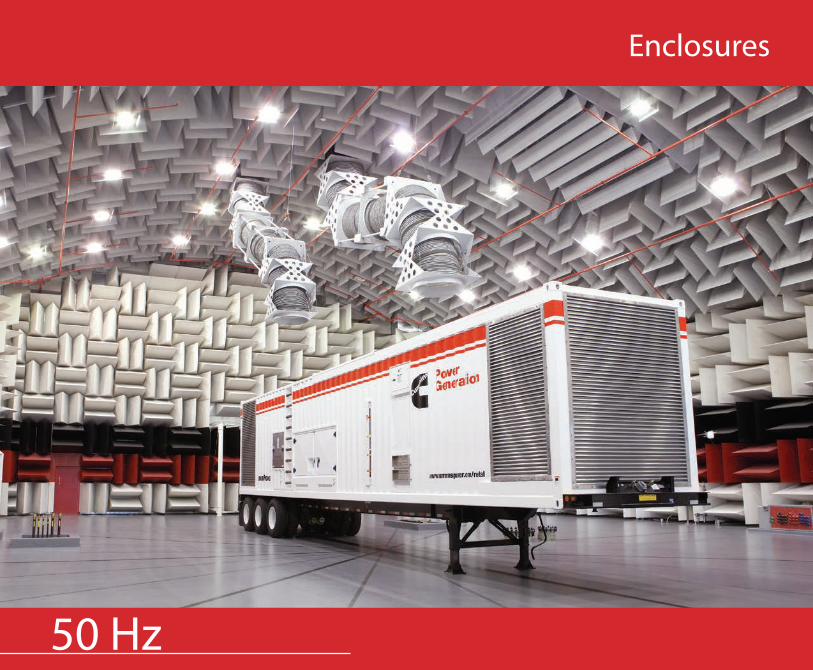
24 2550 Hz
Enclosures
26 27
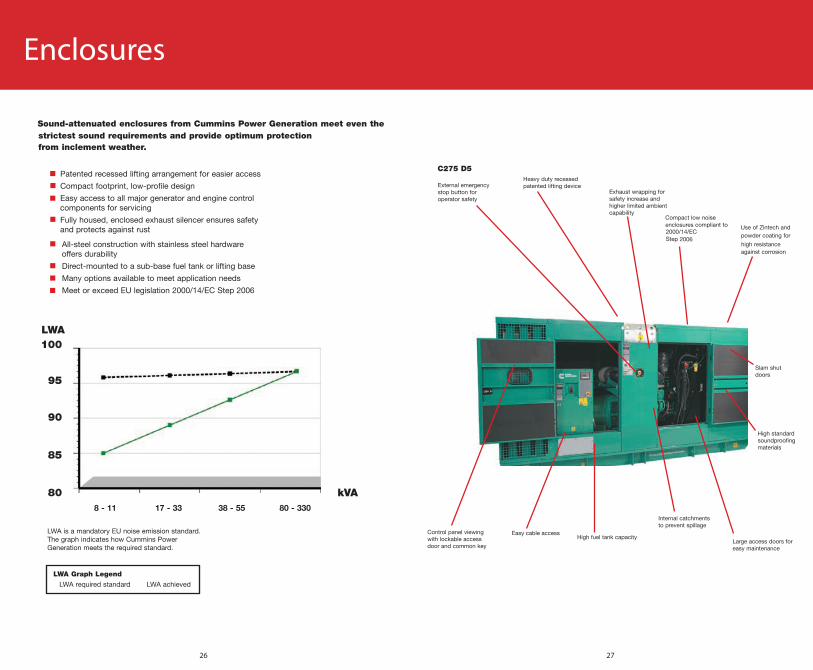
Enclosures

28 29
Enclosures
50 Hz - DIESEL RANGE
Model Name
Standby kVA
Dimensions (mm) L x W x H
Wet Weight without fuel (kg)
Sound Levels @ 75% load Tank(L)dBA @ 1m dBA @ 7m
C350D5 350 5108 X 1563 X 2447 4798 76 69 900
C400D5 400 5109 X 1563 X 2447 4975 76 69 900
C400D5e 400 5110 X 1563 X 2447 5183 76 69 711
C440D5 440 5110 X 1563 X 2447 4975 76 69 900
C450D5e 450 5106 X 1553 X 2447 5426 77 69 711
C450D5eB 450 5092 X 1564 X 2446 5281 77 70 834
C500D5 500 5093 X 1564 X 2446 5281 78 71 834
C500D5e 500 5106 X 1553 X 2447 5426 77 69 711
C550D5e 550 5106 X 1553 X 2447 5576 77 70 711
Model Name
Standby kVA
Dimensions (mm) L x W x H
Wet Weight without fuel (kg)
Sound Levels @ 75% load Tank(L)dBA @ 1m dBA @ 7m
C17D5 16.5 2082 X 987 X 1525 1032 77 67 150
C22D5 22 2082 X 987 X 1525 1056 77 67 150
C28D5 27.5 2082 X 987 X 1525 1079 77 67 150
C33D5 33 2242 X 967 X 1513 1219 75 65 175
C38D5 38 2242 X 967 X 1513 1232 75 65 175
C44D5 44 2600 X 1115 X 1795 1524 77 68 150
C55D5 55 2600 X 1115 X 1795 1535 77 67 150
C66D5 66 2600 X 1115 X 1795 1584 77 68 150
C90D5 90 3151 X 1142 X 1714 2213 78 69 350
C110D5 110 3151 X 1142 X 1714 2232 78 69 350
C150D5 150 3460 X 1090 X 2387 2176 76 67 448
C170D5 170 3460 X 1090 X 2387 2228 79 67 448
C175D5e 175 3900 X 1100 X 2246 3160 77 69 464
C200D5e 200 3900 X 1100 X 2246 3301 77 69 464
C220D5e 220 3900 X 1100 X 2246 3301 77 69 464
C250D5e 250 4253 X 1424 X 2224 3924 77 69 691
C275D5 275 4253 X 1424 X 2224 3924 77 69 691
C275D5e 275 4253 X 1424 X 2224 4147 77 69 691
C300D5 300 4253 X 1424 X 2224 4147 77 69 691
C300D5e 300 4253 X 1424 X 2224 4147 77 69 691
C330D5 330 4253 X 1424 X 2224 4147 77 69 691
C330D5e 330 4253 X 1424 X 2224 4147 77 69 691
50 Hz - DIESEL RANGE
Model Name PowerBox Dimensions
Sound Levels @ 75% load Optional Tank
(L)dBA @ 1m dBA @ 7m
C700D5 PB-20S 20’ ISO 79 72 500L
C825D5A PB-20S 20’ ISO TBA TBA 500L
C1000D5 PB-20S 20’ ISO 84 77 500L
C1100D5B PB-20S 20’ ISO 82 77 500L, 2000L
C1400D5 PB-40S 40’ ISO HC 82 77 500L, 2000L
C1675D5 PB-40S 40’ ISO HC 82 77 500L, 2000L
C1675D5A PB-40S 40’ ISO HC 82 77 500L, 2000L
POWERBOX 50 Hz RANGE
Enclosures

30 3150 Hz
Rental Power
32 33
Notes:
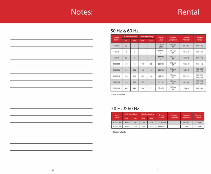
Model Name
50 Hz Prime Rating 60 Hz Prime Rating Engine Model
Emissions Compliance
Standard Alternator
Standard ControlkVA kWe kVA kWe
C20D5R 20 16 - - V2403-M-E3BG
EU Stage IIIA PI144D1 PCC 1302
C40D5R 40 32 - - 4BTAA3.3-G11
EU Stage IIIA UC224C PCC 1302
C60D5R 60 48 - - 4BTAA3.3-G11
EU Stage IIIA UC224E PCC 1302
C100D2R 100 80 110 88 QSB5-G5 EU Stage IIIA UC274C PCC 1302
C150D2R 150 120 169 135 QSB7-G5 EU Stage IIIA UC274F PCC 1302/
PCC 3300
C200D2R 200 160 225 180 QSB7-G5 EU Stage IIIA UC274H PCC 1302/
PCC 3300
C250D2R 250 200 281 225 QSL9-G3 EU Stage IIIA UC274K PCC 1302/
PCC 3300
C300D2R 300 240 344 275 QSL9-G7 EU Stage IIIA HCI4D PCC 3300
Model Name
50 Hz Prime Rating 60 Hz Prime Rating Engine Model
Emissions Compliance
Standard Alternator
Standard ControlkVA kWe kVA kWe
C1000D2R 1000 800 1160 928 KTA38-G14 - HCI634K PCC 3300
C1250D2R 1258 1006 1400 1120 KTA50-G3 - P7B PCC 3300
50 Hz & 60 Hz
50 Hz & 60 Hz
Rental
- Not Available
- Not Available
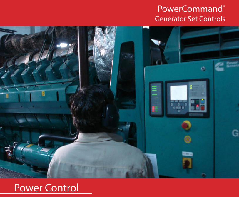
34 35Power Control
PowerCommand®
Generator Set Controls

36 37
Controls
• Standard • Option - Not Available
Main FeaturesPowerCommand Generator Control
PS 0500 PC 1.1/1.2
PCC 2100 PC 2.2 PCC
3201 PC 3.3 PC 3.3MLD
General
AVR - • • • • • •
Electronic Governing - • • • • • •
Glow Plug Control • • • • - • •
Cycle Cranking • • • • • • •
Full Authority Engine Control - • • • • • •
Networking (LonWorks) - - • - • - -
Networking (ModBus) - • - • - • •
Fault History • • • • • • •
Operator Interface
Manual Start/Stop • • • • • • •
Auto/Remote Start • • • • • • •
Exercise Function - - - • • • •
Auto LED • • - • - • •
Not in Auto LED • • • • • • •
Manual LED • • • • • • •
Common Shutdown LED • • • • • • •
Common Warning LED • • • • • • •
Exercise LED - - - • • • •
Emergency Stop (Local and Remote) • • • • • • •
Alphanumeric Screen • • • • • • •
Remote Start Input Active Led • • • • • • •
Fault Reset • • • • • • •
Measurement & Instrumentation - Engine
Oil Pressure • • • • • • •
Oil Temperature - - • • • • •
Water Temperature • • • • • • •
Engine Speed • • • • • • •
Hours Run • • • • • • •
Number of Starts • • • • • • •
Battery Voltage • • • • • • •
Exhaust Temperature - - - - • - -
Controls
• Standard • Option - Not Available
Main FeaturesPowerCommand Generator Control
PS 0500 PC 1.1/1.2
PCC 2100 PC 2.2 PCC
3201 PC 3.3 PC 3.3MLD
Measurement & Instrumentation - Alternator
3 Phase L-L & L-N Voltage & Frequency • • • • • • •
3 Phase Current • • • • • • •
kWh - - • • • • •
Total kVA • • • • • • •
Total kW & kVAr - - • • • • •
PF - - • • • • •
Per Phase kVAr, kW - - • • • • •
Per Phase kVA • - • • • • •
Shutdown Protection & Indication - Engine
Low Fuel Level - • • • • • •
High Fuel Level - - • • - • •
Low Oil Pressure • • • • • • •
High Engine Coolant Temperature • • • • • • •
Failure to Crank Shutdown • • • • • • •
Over Crank (Failure to Start) • • • • • • •
Overspeed - • • • • • •
Shutdown Protection & Indication - Alternator
Under & Over Voltage • • • • • • •
Under & Over Frequency • • • • • • •
Overcurrent - • • • • • •
Earth Leakage - • • • • • •
Reverse Power - - • • • • •
Reverse Var - - • • • • •
Threshold Warning Indications
Low Oil Pressure • • • • • • •
Low Engine Coolant Temperature • • • • • • •
High Engine Coolant Temperature • • • • • • •
Low Coolant Level - - • • • • •
Low Battery Voltage • • • • • • •
High Battery Voltage • • • • • • •
Battery Alternator Charge Fault - • - • - • •
Overcurrent - • • • • • •
Overload - • - • - • •
AMM - AmpSentry Maintenance Mode - - • • • • •

38 39
Controls
• Standard • Option - Not Available
Main FeaturesPowerCommand Generator Control
PS 0500 PC 1.1/1.2
PCC 2100 PC 2.2 PCC
3201 PC 3.3 PC 3.3MLD
Paralleling Capability
Auto Synchronizing (Isolated Bus) - - - - • • •
kW & VAr Load Sharing Control - - - - • • •
Auto Synchronizing (Utility Bus) - - - - • • •
Base Load - - - - • • •
Synchroscope - - - - • • •
Peak Lopping - - - - - • •
Masterless Load Demand - - - - - - •
Power Transfer Function
Open Transition Transfer - - - - • • •
Hard Closed Transition - - - - • • •
Soft Closed Transition (Ramping) - - - - • • •
Transfer & Base Load (Utility) - - - - • • •
Gen/Mains Breaker Control - - - - • • •
Gen/Mains Breaker Status Protection - - - - • • •
Environment
Operating Temp. Range -40˚C to +70˚C - • • • • • •
Operating Temp. User Interface -20˚C to +70˚C • • • • • • •
Humidity up to 95% (Non-condensing) • • • • • • •
Codes & Standards
CE Compliant • • • • • • •
NFPA 110 - • • • • • •
UL508 Listed - - • • • • •
UL Certified - • • • • • •
Controller Inputs/Outputs
Digital Inputs (Shutdown, Warning or Status) 1 4 4 4 4 4 4
Relay Outputs 1 2 4 4 4 4 4
Configurable Input/Output - • • • • • •
Notes:

Load Transfer
PowerCommand®
Automatic Transfer Switches

42 43
Main FeaturesAutomatic Transfer Switches
GTEC OTEC OTPC BTPC CHPC/OHPC
Specifications
Amp Range 40 - 2000 40 - 1200 40 - 4000 150 - 4000 125 - 800
(Select the ATS to suit the largest-sized supply (amps) that will be applied to the ATS)
Voltage Rating up to 480VAC
up to 600VAC
up to 600VAC
up to 600VAC
up to 600VAC
Phases 1 or 3 1 or 3 1 or 3 1 or 3 1 or 3
Frequency 50 or 60Hz 50 or 60Hz 50 or 60Hz 50 or 60Hz 50 or 60Hz
Poles 3, 4 3, 4 3, 4 3, 4 2, 3, 4
Warranty 1 year up to 10 years
up to 10 years
up to 10 years
up to 10 years
Switch Mechanism
Open Transition • • • • •
Closed Transition - - •(>1000A) •
•(CHPC only)
Programmed Transition • • • • -
Bypass Isolation - Open Transition - - - • -
Bypass Isolation - Closed Transition - - - • -
Bypass Isolation - Programmed Transition - - - • -
Utility-to-Genset • • • • •
Utility-to-Utility - -
•(not avail-able with
closed transition)
•(not avail-able with
closed transition)
• (OHPC only)
Genset-to-Genset - - • •(<1000A) •
Service Entrance Available - •(≤1000A)
•(≤1000A) - -
Mechanical Interlock • • • •
• (disabled
during closed
transition)
Load Monitoring - - • • •
WCR with Specified Circuit Breakers 25-65kA 14-85kA 14 - 100kA 14 - 100kA 42 - 85kA
WCR with Current Limiting Fuses 26-120kA 200kA 200kA 200kA 200kA
Short-time Ratings / 30-cycle Rating (UL Listed) - - - - 10-42kA
Control
Type of Control Basic micro
Basic micro
PCC L1 or L2 PCC L2 PCC L2/
L1 or L2
Automatic Transfer Switches
• Standard • Option - Not Available
Main FeaturesAutomatic Transfer Switches
GTEC OTEC OTPC BTPC CHPC/OHPC
Operator Panel
Load Connected to Normal LED • • • • •
Normal Source Available LED • • • • •
Load Connected to Emergency LED • • • • •
Emergency Source Available LED • • • • •Load AC Metering Bar Graph - - • • •Alphanumeric Display - - • • •
Panel Security Lock - - • • •
Control Functions
3-phase Voltage Sensing - Utility • • • • •
3-phase Voltage Sensing - Generator Single Phase
Single Phase • • •
Electrical Isolation from AC - Mains High Impedance
High Impedance Transformer Transformer Transformer
O/U Voltage Sensing Utility U/V Only U/V Only • • •
O/U Voltage Sensing Generator U/V Only U/V Only • • •Voltage Sensing Accuracy +/- 2% +/- 2% +/- 2% +/- 2% +/- 2%O/U Frequency Sensing Utility - - • • •
O/U Frequency Sensing Generator U/F Only U/F Only • • •Voltage Imbalance - - L2 Control L2 Control •Phase Rotation - - L2 Control L2 Control •Loss of Phase - • • • •
Transfer Normal to Emergency (Time) 0 - 300 secs
0 - 300 secs 0 -120 secs 0 -120 secs 0 -120 secs
Re-transfer Emergency to Normal (Time) 0 - 30 mins 0 - 30 mins 0 - 30 mins 0 - 30 mins 0 - 30 mins
Engine Start Delay (Adjustable) 0 - 10 sec 0 - 10 sec 0 - 120 secs
0 - 120 secs
0 - 120 secs
Time Delay to Engine Stop 0 - 30 mins 0 - 30 mins 0 - 1800 secs
0 - 1800 secs
0 - 1800 secs
Programmed Transition (Time) 0 - 10 sec 0 - 10 sec 0 - 60 secs 0 - 60 secs 0 - 60 secsFail to Disconnect Timer (Closed Transition) - - Level 2
Cont• •
Time & Date-Stamped Event Log - - • • •
Historical Data Display - - • • •Remote Monitoring/Communication - - • • •System Data Display - - • • •Elevator Signal Module • • • • •Load Sequencing - - • • •Fully-Programmable Exerciser Clock • • • • •Exercise Clock • • • • •
Real-Time Clock - - • • •
Automatic Transfer Switches
• Standard • Option - Not Available

44 45Paralleling and Switchgear
PowerCommand®
Paralleling Systems
46 47
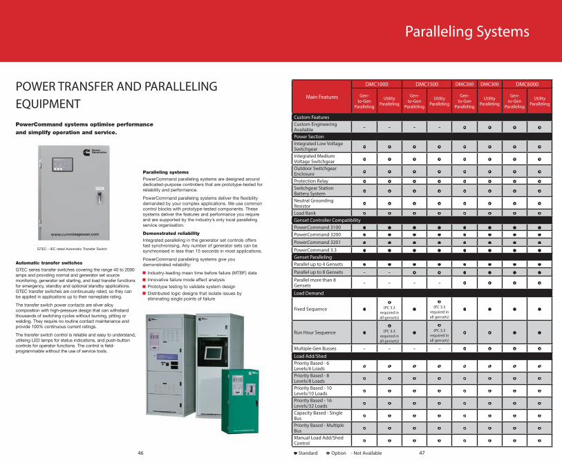
POWER TRANSFER AND PARALLELINGEQUIPMENT
Main Features
DMC1000 DMC1500 DMC200 DMC300 DMC8000
Gen-to-Gen
Paralleling
Utility Paralleling
Gen-to-Gen
Paralleling
Utility Paralleling
Gen-to-Gen
Paralleling
Utility Paralleling
Gen-to-Gen
Paralleling
Utility Paralleling
Custom FeaturesCustom Engineering Available - - - - • • • •
Power SectionIntegrated Low Voltage Switchgear • • • • • • • •
Integrated Medium Voltage Switchgear • • • • • • • •
Outdoor Switchgear Enclosure • • • • • • • •
Protection Relay • • • • • • • •Switchgear Station Battery System • • • • • • • •
Neutral Grounding Resistor • • • • • • • •
Load Bank • • • • • • • •Genset Controller CompatibilityPowerCommand 3100 • • • • • • • •PowerCommand 3200 • • • • • • • •PowerCommand 3201 • • • • • • • •PowerCommand 3.3 • • • • • • • •Genset ParallelingParallel up to 4 Gensets • • • • • • • •Parallel up to 8 Gensets - - • • • • • •Parallel more than 8 Gensets - - - - • • • •
Load Demand
Fixed Sequence ••
(PC 3.3 required in all gensets)
••
(PC 3.3 required in all gensets)
• • • •
Run Hour Sequence ••
(PC 3.3 required in all gensets)
••
(PC 3.3 required in all gensets)
• • • •
Multiple Gen Busses - - - - • • • •Load Add/ShedPriority Based - 6 Levels/6 Loads • • • • • • • •
Priority Based - 8 Levels/8 Loads • • • • • • • •
Priority Based - 10 Levels/10 Loads • • • • • • • •
Priority Based - 16 Levels/32 Loads • • • • • • • •
Capacity Based - Single Bus • • • • • • • •
Priority Based - Multiple Bus • • • • • • • •
Manual Load Add/Shed Control • • • • • • • •
• Standard • Option - Not Available
Paralleling Systems
48 49
Main Features
DMC1000 DMC1500 DMC200 DMC300 DMC8000
Gen-to-Gen
Paralleling
Utility Paralleling
Gen-to-Gen
Paralleling
Utility Paralleling
Gen-to-Gen
Paralleling
Utility Paralleling
Gen-to-Gen
Paralleling
Utility Paralleling
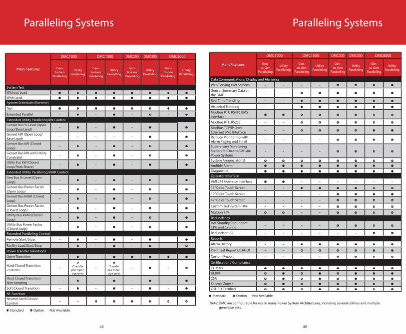
System TestWithout Load • • • • • • • •With Load • • • • • • • •System Scheduler (Exercise)Test • • • • • • • •Extended Parallel - • - • - • - •Extended Utility Paralleling kW ControlGenset Bus % Level (Open Loop/Base Load) - • - • - • •
Genset kW (Open Loop/Base Load) - - - - - • •
Genset Bus kW (Closed Loop) - • - • - • •
Genset Bus kW with Utility Constraint - • - • - • •
Utiity Bus kW (Closed Loop/Peak Shave) - • - • - • •
Extended Utility Paralleling kVAR ControlGen Bus % Level (Open Loop) - • - • - • •
Genset Bus Power Factor (Open Loop) - • - • - • •
Genset Bus kVAR (Closed Loop) - • - • - • •
Genset Bus Power Factor (Closed Loop) - • - • - • •
Utility Bus kVAR (Closed Loop) - • - • - • •
Utility Bus Power Factor (Closed Loop) - • - • - • •
Extended Paralleling Control
Remote Start/Stop - • - • - • •
Facility Load Start/Stop - • - • - • •Power Transfer Transitions
Open Transition - • - • • • • •
Hard Closed Transition <100 ms -
•(Transfer
pair topol-ogy only)
-•
(Transfer pair topol-ogy only)
- • - •
Hard Closed Transition Non-ramping - • - • - • - •
Soft Closed Transition - • - • - • - •NE FunctionNeutral Earth Device Control - - • • • • • •
• Standard • Option - Not Available
Paralleling Systems
Main Features
DMC1000 DMC1500 DMC200 DMC300 DMC8000
Gen-to-Gen
Paralleling
Utility Paralleling
Gen-to-Gen
Paralleling
Utility Paralleling
Gen-to-Gen
Paralleling
Utility Paralleling
Gen-to-Gen
Paralleling
Utility Paralleling
Data Communications, Display and Alarming
Web Serving HMI Screens - - - - • • • •Genset Summary Data at the DMC - - • • • • • •
Real Time Trending - - • • • • • •
Historical Trending - - • • • • • •Modbus RTU RS485 BMS Interface • • • • • • • •
Modbus RTU RS232 - - • • • • • •Modbus TCP/IP Over Ethernet BMS Interface - - • • • • • •
Remote Monitoring with Alarm Paging and Email - - - - • • • •
Supervisory Monitoring Station for On-site/Off-site Power Systems
- - - - • • • •
System Annunciator(s) • • • • • • • •Audible Alarm • • • • • • • •Diagnostics • • • • • • • •Operator Interface
HMI 211 Operator Interface • • - - - - - -15” Color Touch Screen - - • • • • • •
19” Color Touch Screen - - - - • • • •
42” Color Touch Screen - - - - • • • •
Customized System HMI - - - - • • • •
Multiple HMI • • - - • • • •RedundancyHot Standby Redundant CPU and Cabling - - - - • • • •
Redundant I/O - - - - - - • •Reports
Alarm History - - • • • • • •
Plant Test Report (JCAHO) - - • • • • • •
Custom Report - - - - • • • •Certification / Compliance
CE Mark • • • • • • • •UL891 • • • • • • • •CSA • • • • • • • •Seismic Zone 4 • • • • • • • •OSHPD Certified • • • • • • • •
• Standard • Option - Not Available
Note: DMC are configurable for use in many Power System Atchitectures, including several utilities and multiple generator sets.
Paralleling Systems

50 51
Monitoring
PowerCommand®
Remote Monitoring Systems

52 53
Features/Functionality PowerCommand 500 PowerCommand 550
Number of Devices Supported
Up to 2 devices(any combination)
Up to 12 devices(any combination)
Supported Device Types
Generator sets, transfer switches, CCM-T, CCM-G, Aux 101/102
Generator sets, transfer switches, CCM-T, CCM-G, Aux 101/102
Device I/Os 2 discrete inputs, 2 discrete outputs, 1 resistive input
2 discrete inputs, 2 discrete outputs, 1 resistive input
Expandable I/O Modules
AUX101: 8-configurable inputs /8-discrete outputs
AUX102: 4-non configurable discrete inputs / 8-discrete outputs
AUX101: 8-configurable inputs /8-discrete outputs
AUX102: 4-non configurable discrete inputs / 8-discrete outputs
Notifications SMTP/Email, SMS/Text and SNMP traps
SMTP/Email, SMS/Text and SNMP/Traps
Connection to Supported Devices Modbus Modbus
Data Logging YesNo data or report export
YesData and report export
Extended Memory Yes Yes
Certification/Compliance UL, CSA, CE, FCC, RoHS UL, CSA, CE, FCC, RoHS
Languages English, Brazilian Portuguese, Chinese, French and Spanish
English, Brazilian Portuguese, Chinese, French and Spanish
Power Supply Connection 8-32 DC 8-32 DC
Warranty Period 12 months 12 months
Remote Monitoring Systems Notes:

54 55Service and Maintenance
PowerCommand®
InPower™

56 57
InPower™
Main Functions
InPower
Pro Lite
Direct connection capability from a personal computer to PowerCommand generator set controls, transfer controls and system controls • •
Connects to generator set or transfer switch controls via modem or to multiple controls • •Allows the monitored equipment to send alarm information to a connected computer • •Configurable for units of measurement, and level of user access (read only, read/change values, administrator) • •
Adjustment of nearly every adjustment parameter within the connected control system, including parameters such as voltage and frequency levels, gains, protection set-points and other values
• •
Convenient programming of configurable inputs in the controllers • •Viewing of equipment history, fault codes, and data associated with fault codes • •Generates reports of monitored data • •Allows released firmware upgrades on PowerCommand generator set controls • •Plots critical parameters in a strip chart format, and export data to 3rd party software tools for manipulation and viewing • •
Simulates fault conditions in generator set controls in compliance with NFPA 110 require-ments to demostrate functionality of the controller and monitoring equipment in a facility • •
Simulate fault conditions in genset controls in compliance to NFPA 110 requirements to demostrate functionality of the controller and monitoring equipment in a facility. • •
• Available - Not Available
Networking & Software

58 59
Notes:Notes:

© 2015 Cummins Power Generation
Inc.
All rights reserved.
Cummins Power Generation and
Cummins are registered trademarks
of Cummins Inc. PowerCommand® is
a registered trademark of Cummins
Power Generation.
All information contained within this
document was correct at time of
Cummins Africa Head Quarters - Johannesburg, ZA +27 11 589 8400
Cummins Afrique de l’Ouest, Senegal Head Office +221 3385 57070 Cummins AngolaHead Office +244 927 443 578
Cummins Cote D’Ivoire Head Office +255 2135 5057
Cummins Ghana Head Office +233 302 301 451
Cummins Southern Africa, Johannesburg, ZA Head Office +27 11 321 8700
Cummins North Africa, MoroccoHead Office +212 0 529 04 39 12 Cummins West Africa, Nigeria Head Office +234 1 277 2880
See your distributor for more information or visit power.cummins.com.
Global Brochure 01/2016