afd user's manual - pushcorp · afd1100 adjustable force device manual april, 2001 par01641-1...
TRANSCRIPT

AFD1100Adjustable Force
DeviceManual
April, 2001 U.S. Patent No. 5,448,146PAR01641-1
PUSHCORP, INC.Dallas, Texas

CAUTIONActive Force Devices contain
calibrated electronics.HANDLE WITH CARE DO NOT DROP
DO NOT USE LUBRICATED AIR.This device requires a dry, non-
lubricated 80 to 90 psi (5.5 – 6.2 bar)air supply filtered to 5 µm and a 0.3
micron oil mist separator.Non-compliance with theserequirements will void themanufacturer’s warranty.
(See Section 4.3)
All fasteners, mounting holes andpipe threads on this tool are
METRIC.
All PushCorp, Inc. electrical cables are rated forhigh twist and flex robotic applications with a
minimum cable bending radius specification of125mm (5 in). Cable damage resulting from
failure to abide by this specification will not becovered under warranty.

PUSHCORP, INC. AFD1100 Manual
Table of Contents
1.0 LIMITED WARRANTY...........................................................................................1
2.0 GENERAL OVERVIEW.........................................................................................3
3.0 QUICK START.......................................................................................................3
4.0 INSTALLATION.....................................................................................................4
4.1 Mounting Process Equipment..........................................................................................................4
4.2 Mounting the AFD1100...................................................................................................................5
4.2.1 Mounting the AFD1100-1 Vertical and AFD1100-2 Horizontal.....................................................5
4.2.2 Mounting the AFD1100-3 Table Top............................................................................................5
4.3 Maximum Carriage Load Calculations.............................................................................................7
4.4 Pneumatic Connection....................................................................................................................9
5.0 ADJUSTING CARRIAGE PRELOAD..................................................................11
6.0 TECHNICAL SPECIFICATIONS.........................................................................13
7.0 PREVENTATIVE MAINTENANCE SCHEDULE.................................................14
PUSHCORP, INC. AFD1100 Manual 1
1.0 Limited WarrantyDuration:
One year from date of delivery to the original purchaser.
Who gives this warranty (warrantor):PushCorp, Inc.Telephone: (972) 840-0208
Corporate Address:P. O. Box 181915Dallas, Texas 75218
Shipping Address:3001 W. Kingsley Rd.Garland, Texas 75041
Who receives this warranty (purchaser):
The original purchaser (other than for purposes of resale) of the PushCorp, Inc.product
What products are covered by this warranty:
Any PushCorp, Inc. Adjustable Force Device or Adjustable Force Deviceaccessory supplied or manufactured by the Warrantor.
What is covered under this warranty:
Defects in material and/or workmanship which occur within the duration of thewarranty period.
What is NOT covered in this warranty:
A. IMPLIED WARRANTIES, INCLUDING THOSE OF MERCHANT-ABILITYAND FITNESS FOR A PARTICULAR PURPOSE ARE LIMITED TO ONEYEAR FROM THE DATE OF ORIGINAL PURCHASE. Some states do notallow limitations on how long an implied warranty lasts, so the abovelimitations may not apply to you.
B. ANY INCIDENTAL, INDIRECT, OR CONSEQUENTIAL LOSS, DAMAGE orEXPENSE THAT MAY RESULT FROM ANY DEFECT, FAILURE,MALFUNCTION OF THE PUSHCORP, INC. PRODUCT. Some states do notallow the exclusion or limitation of incidental or consequential damages sothe above limitation or exclusion may not apply to you.
C. Any failure that results from an accident, purchaser's abuse, neglect,unauthorized repair or failure to operate the products in accordance with theinstructions provided in the owner's manual(s) supplied with the product.
Responsibilities of the Warrantor under this warranty:
Repair or replace, at Warrantor's option, products or components which havefailed within the duration of the warranty period.

PUSHCORP, INC. AFD1100 Manual 2
Responsibilities of the purchaser under this warranty:
A. Deliver or ship the PushCorp, Inc. product or component to PushCorp, Inc.Service Center, Dallas, TX. Freight and insurance costs, if any, must beborne by the purchaser.
B. Use reasonable care in the operation and maintenance of the product asdescribed in the owner's manual(s).
When warrantor will perform repair or replacement under this warranty:
Repair or replacement will be scheduled and serviced according to the normalwork flow at the service center, and depending on the availability of replacementparts. Purchasers requiring quicker repair may receive such with payment of aPushCorp, Inc. predetermined expediting fee.
This Limited Warranty gives you specific legal rights and you may also have other rights which vary from state to state.
PUSHCORP, INC. AFD1100 Manual 3
2.0 General OverviewThe PushCorp, Inc. AFD1100 Adjustable Force Devices (US Patent No. 5,448,146)provide a superior force application system. The AFD can be placed in any position toenable a variety of manufacturing operations requiring a consistent applied force with1.6 inches (40 mm) of compliant stroke. The AFD is designed to withstand continuoususe in harsh industrial grinding, polishing, and drilling operations.
The AFD1100 utilize a pneumatic actuator to provide the force and a load cell forcesensor to provide closed-loop feedback to an FCU1000 Active Compliance Controller.The AFD1100 can apply up to a maximum 100 lbs. (445 N) of force. The AFD containsan accelerometer that monitors orientation and allows the unit to automaticallycompensate for gravitational and inertial effects. A linear potentiometer is also presentwithin the AFD to sense the position of the Carriage.
Only two external connections are required to operate the AFD1100. First, dry, non-lubricated, filtered 80 - 90 psi (5.5 – 6.2 bar) supply air must be provided through flexibletubing. Second, the AFD must be connected to the FCU1000 Controller with aPushCorp high flex multi-conductor cable. An optional Purge Port is provided forapplications where excessive fine dust particles are created. This Purge Portconnection provides additional airflow and internal positive pressure to minimizecontamination entering the AFD. The Carriage has threaded mounting holes to provideeasy process equipment attachment.
All these features combine to make the PushCorp AFD1100 Adjustable Force Device arugged, state-of-the-art technology capable of providing reliable, precise, and consistentresults in a variety of industrial applications.
3.0 Quick StartThis section contains step-by-step instructions on how to quickly get the AFD1100Adjustable Force Device up and running for a quick test of its capabilities. Completedetails on all the features are described in the sections that follow. It is recommendedthat the user read the entire manual before beginning any operations to fully understandall the aspects and features of the AFD1100.
Step 1: Carefully unpack the AFD1100 Force Device and the FCU1000 Controller.Verify that all parts indicated on the packing list are present and in goodcondition. If there is a problem, please notify the factory immediately sothat corrective action may be promptly initiated.
Step 2: Securely attach the AFD1100 Mounting Bracket to the manipulatormounting flange or support table per Section 4.2.
Step 3: Connect a dry, non-lubricated, 5 µm filtered 80 to 90 psi (5.5 to 6.2 bar) airsupply to the force device per Section 4.3.
Step 4: Consult the FCU1000 Manual for electrical connections and software setupinformation.
Please read the following sections to learn the full potential and features of thePushCorp AFD1100 Adjustable Force Device.

PUSHCORP, INC. AFD1100 Manual 4
4.0 Installation
4.1 Mounting Process Equipment
The AFD1100 Adjustable Force Device can accommodate many different types ofprocess equipment. PushCorp provides a variety of standard process equipment suchas weld shavers, high speed motors, plus other specialized tooling. Many end usersalso develop process equipment for their own applications. The AFD can be orientedparallel or perpendicular to the manipulator mounting flange, although it is important tonote that the AFD can apply force only in the direction of Carriage translation.
When mounting process equipment to the Carriage extreme care should be taken whiledesigning and installing the brackets. Correctly designed brackets will increase thestiffness of the Carriage by becoming an external superstructure for the Carriage. TheCarriage can gain a tremendous amount of rigidity if this approach is executed correctly.Incorrectly designed brackets will deform the Carriage surface causing internal LinearRail misalignment. A symptom of Carriage deformation is “slop” or “binding” of theCarriage. A deformed or loose Carriage will damage the Linear Rails and effect theconsistency of your process. The Carriage preload is correctly set at the factory andshould not require adjustment. If the Carriage becomes loose or binds after installingthe process equipment, then the brackets must be removed and the problem corrected.PushCorp, Inc. can design and fabricate brackets to user supplied specifications as anoption.
Figure 1. Carriage bolt hole pattern

PUSHCORP, INC. AFD1100 Manual 5
The bolt pattern on the Carriage has been designed to facilitate motor installation in anumber of configurations. The Carriage has (14) fourteen M8 x 1.25 mounting holeswith a depth of 0.52 inch (13 mm) to provide secure attachment points. The mountingholes are spaced as shown in Figure 1. The Carriage also has (2) two 5mm dowel pinholes to facilitate alignment (See Figure 1 for location). These dowel pin holes areoversized to allow the pins to be glued into place using Loctite 609, or equivalent. DONOT press pins into the AFD Carriage, as this will damage the linear rails.
Caution: The Fastener Tightening Torque Specs chart in Section 6.0 should beused to determine proper fastener length and torque for fasteners into theCarriage. This is to prevent pull-out of the Carriage helicoil inserts. Fastenersmust not exceed a depth of 0.52 inches (13 mm) into the Carriage as this coulddamage the Linear Rails.
4.2 Mounting the AFD1100
The basic configuration of the AFD1100 force device allows attachment to a stationaryfixture or a robotic manipulator mounting flange. Specifying an AFD1100-1, -2, or -3determines which Mounting Bracket is supplied. Adapter plates or "quick-change"attachments can be used as well for mounting.
4.2.1 Mounting the AFD1100-1 Vertical and AFD1100-2 Horizontal
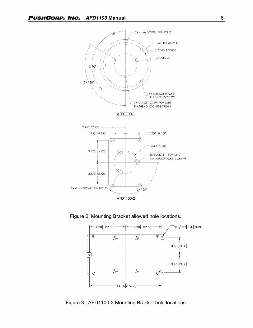
The AFD1100-1 and AFD1100-2 are supplied with a standard Mounting Bracket with a90 mm three hole mounting pattern, See Figure 2. All three holes should be utilized tosecure the Mounting Bracket to the robot mounting flange. If the Mounting Bracket issupplied blank or additional holes are required, it must first be removed from the devicebefore drilling. Four cap screws are used to attach the Mounting Bracket to theAFD1100. Once the Mounting Bracket is removed, mounting holes may be placedanywhere within the crosshatched area shown in Figure 2. PushCorp, Inc. will supplyengineering support to determine the mounting hole locations at no cost.
After drilling the required hole pattern, remove any burrs and clean any machiningresidue from the Mounting Bracket. The Mounting Bracket can then be reattached.
4.2.2 Mounting the AFD1100-3 Table Top
The AFD1100-3 is designed for mounting on a stationary fixture. It has (4) four 0.33”(8.4 mm) mounting holes spaced as shown in Figure 3. The AFD1100-3 Table TopMounting Bracket should not be modified without first consulting PushCorp, Inc.
PUSHCORP, INC. AFD1100 Manual 6
Figure 2. Mounting Bracket allowed hole locations.
Figure 3. AFD1100-3 Mounting Bracket hole locations

PUSHCORP, INC. AFD1100 Manual 7
4.3 Maximum Carriage Load Calculations
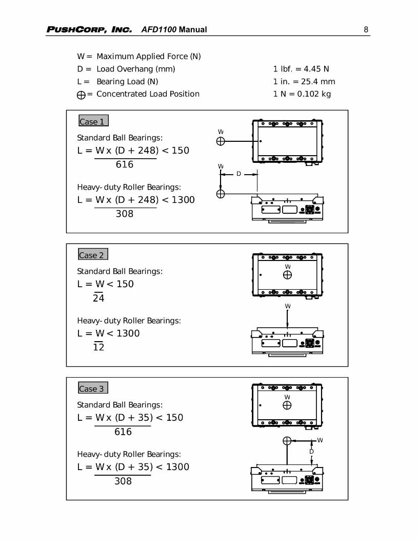
The Linear Rail bearings that support the AFD1100 sliding Carriage have been selectedto provide optimal performance with respect to capacity, size, and low friction. Toensure continued optimal performance it is very important not to overload thesebearings. The following diagrams and associated equations are provided to check yourapplication for excessive loading.
It is important to note that these equations require the use of Metric units. Thenecessary conversions are provided for your convenience. Insert your maximumapplied force and process equipment weight (W) and overhang distances (D) tocalculate an actual bearing load (L) that must be less than the maximum bearing loadshown on the right side of the equation. The life of the bearings is 100,000 meters oflinear motion, at the maximum allowable bearing load value. Exceeding this value (L)will reduce the life and operating at less than this value (L) will increase the life. It iscommon to have combined weight and force loads on the Carriage. These situationsmay require adding two or more of the scenarios shown below. If your tooling is notsimilar to any of the designs listed here, or if the information is not clear, please contactPushCorp Technical Support for assistance. Ball-bearing equations apply to thestandard AFD1100 tools. Roller-bearing equations apply to AFD1100 tools ordered withthe –HD, Heavy-Duty option.
PUSHCORP, INC. AFD1100 Manual 8

PUSHCORP, INC. AFD1100 Manual 9
4.4 Pneumatic Connection
The AFD1100 Adjustable Force Devices require a dry, non-lubricated, 5 µm filtered, 80to 90 psi (5.5 – 6.2 bar) air supply. Failure to provide supply air to these specificationscan degrade performance and will void any warranty repairs concerning pneumaticcomponents. Filtered air is required since the high speed servo spool valve used in theAFD cannot tolerate ANY foreign material in the supply air. Additionally, a minimum 80psi (5.5 bar) air pressure must be maintained at the supply air port for the device tooperate within published specifications. Operating at lower air pressure can causeinferior force control performance and possibly instability. Operating the AFD atpressures over 90 psi (6.2 bar) will activate a pressure relief valve inside the tool. Thisvalve prevents damage to the internal load cell due to operating the tool with excessivepressure. This relief valve is strictly a protective mechanism and should not be used asa pressure regulator device.
The pneumatic supply system should be configured as shown in the Figure 4.
Figure 4. Pneumatic configuration
If water condensation is a problem in your air supply system, an air dryer device ishighly recommended. The ideal solution is an industrial chiller dryer capable of reducingthe dewpoint to less than 32 F (0C). Moisture inside the force device will causepremature failure that will not be covered under warranty.
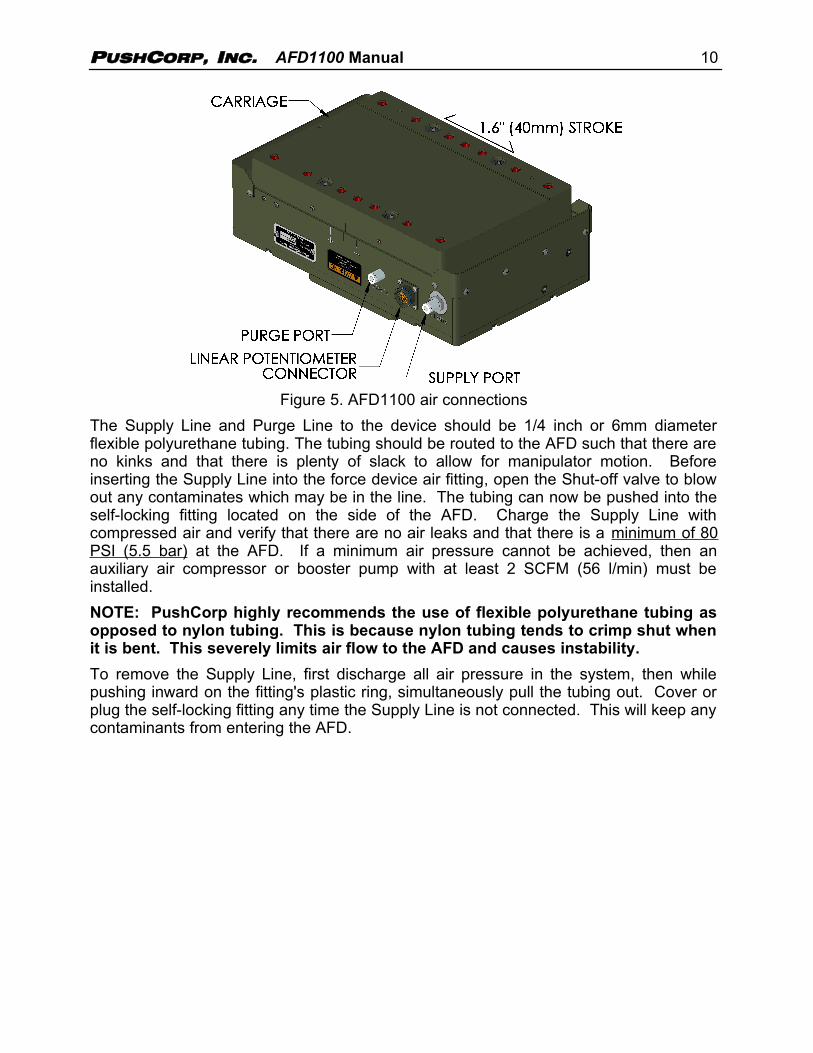
Under most circumstances the standard internal purge will provide sufficient air to keepthe AFD1100 free of contaminates. In applications where the environment contains verysmall suspended particulate matter, additional purge air flow must be used to ensurethat the AFD remains clear of foreign matter. An auxiliary Purge Port on the AFD1100(See Figure 5.) provides a pneumatic connection to supply this additional air flow. Theport accepts a metric R 1/8 tapered pneumatic fitting. PushCorp can provide fittings forEnglish or metric tubing. The input pressure to the purge port can range from 10 PSI to60 PSI (0.7 – 4.1 bar) with a flow rate of 0.5 to 2.0 SCFM (14 – 56 l/min) depending onthe application. The purge air must be dry and non-lubricated, however it need only befiltered to 20 microns.
PUSHCORP, INC. AFD1100 Manual 10
Figure 5. AFD1100 air connections
The Supply Line and Purge Line to the device should be 1/4 inch or 6mm diameterflexible polyurethane tubing. The tubing should be routed to the AFD such that there areno kinks and that there is plenty of slack to allow for manipulator motion. Beforeinserting the Supply Line into the force device air fitting, open the Shut-off valve to blowout any contaminates which may be in the line. The tubing can now be pushed into theself-locking fitting located on the side of the AFD. Charge the Supply Line withcompressed air and verify that there are no air leaks and that there is a minimum of 80PSI (5.5 bar) at the AFD. If a minimum air pressure cannot be achieved, then anauxiliary air compressor or booster pump with at least 2 SCFM (56 l/min) must beinstalled.
NOTE: PushCorp highly recommends the use of flexible polyurethane tubing asopposed to nylon tubing. This is because nylon tubing tends to crimp shut whenit is bent. This severely limits air flow to the AFD and causes instability.
To remove the Supply Line, first discharge all air pressure in the system, then whilepushing inward on the fitting's plastic ring, simultaneously pull the tubing out. Cover orplug the self-locking fitting any time the Supply Line is not connected. This will keep anycontaminants from entering the AFD.
PUSHCORP, INC. AFD1100 Manual 11
5.0 Adjusting Carriage PreloadThe required preload on the AFD1100 Linear Rails has been set at the factory foroptimal performance and, in general, should not require field adjustment. However,there are situations that could arise that cause the Linear Rails to need adjustment.Often a loose, or tight, Carriage on a new AFD is indicative of an improperly designedprocess equipment bracket. If the problem disappears when the brackets are removedthen this is the case. Normally the Carriage will only require adjustment after removal forfield service.
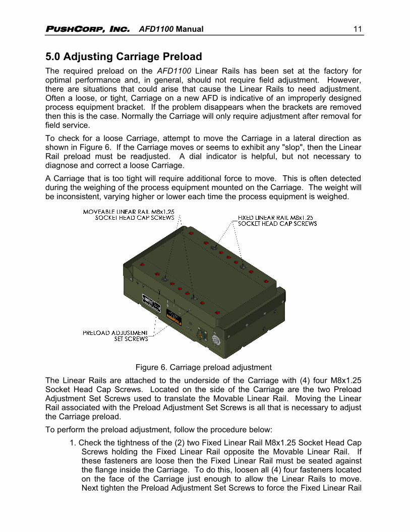
To check for a loose Carriage, attempt to move the Carriage in a lateral direction asshown in Figure 6. If the Carriage moves or seems to exhibit any "slop", then the LinearRail preload must be readjusted. A dial indicator is helpful, but not necessary todiagnose and correct a loose Carriage.
A Carriage that is too tight will require additional force to move. This is often detectedduring the weighing of the process equipment mounted on the Carriage. The weight willbe inconsistent, varying higher or lower each time the process equipment is weighed.
Figure 6. Carriage preload adjustment
The Linear Rails are attached to the underside of the Carriage with (4) four M8x1.25Socket Head Cap Screws. Located on the side of the Carriage are the two PreloadAdjustment Set Screws used to translate the Movable Linear Rail. Moving the LinearRail associated with the Preload Adjustment Set Screws is all that is necessary to adjustthe Carriage preload.
To perform the preload adjustment, follow the procedure below:
1. Check the tightness of the (2) two Fixed Linear Rail M8x1.25 Socket Head CapScrews holding the Fixed Linear Rail opposite the Movable Linear Rail. Ifthese fasteners are loose then the Fixed Linear Rail must be seated againstthe flange inside the Carriage. To do this, loosen all (4) four fasteners locatedon the face of the Carriage just enough to allow the Linear Rails to move.Next tighten the Preload Adjustment Set Screws to force the Fixed Linear Rail

PUSHCORP, INC. AFD1100 Manual 12
to seat against the flange. Tighten the (2) two Fixed Linear Rail M8x1.25Socket Head Cap Screws, which hold the Fixed Linear Rail, to the torquespecified in Section 6.0. The Fixed Linear Rail is now correctly seated and thePreload Adjustment Set Screws can be loosened. You are now ready tocontinue on to preload the Carriage Linear Rails.
2. To preload the Carriage Linear Rails, loosen the Movable Linear Rail M8x1.25Socket Head Cap Screws holding the Movable Linear Rail only enough to allowthe rail to move relative to the inside Carriage surface. The Carriage hasslotted holes on the Movable Linear Rail side which allow the rail to move inthe same direction as the Preload Adjustment Set Screws. Make sure that theMovable Linear Rail M8x1.25 Socket Head Cap Screws are loose beforeattempting to set the preload.
3. If a dial indicator is available, place it against the Carriage surface that containsthe Preload Adjustment Set Screws. Attempt to move the Carriage laterallywhile monitoring the dial indicator. If the reading on the dial indicator varies,then gradually tighten each of the Preload Adjustment Set Screws. Note thatone of the Preload Adjustment Set Screws could require more adjustment thanthe other. When the dial indicator ceases to vary, the preload is set correctly.Do not continue to tighten the Preload Adjustment Set Screws. Too muchpreload on the Linear Rails will cause excessive friction resulting in forceerrors.
4. If a dial indicator is not available, the preload can be adjusted by feel. Attemptto move the Carriage laterally and feel for movement. If the Carriage movesrotate each of the Preload Adjustment Set Screws no more than 5 degrees. Assoon as no lateral movement can be felt, stop rotating the Preload AdjustmentSet Screws. Note that one of the Preload Adjustment Set Screws could requiremore adjustment than the other. Do not over tighten the Preload AdjustmentSet Screws. Over tightening the Preload Adjustment Set Screws will result inexcessive friction and possible deformation of the Carriage. (If the adjustmentcannot be performed, contact the factory service center.)
The Carriage preload should now be correct.
5. After verifying that the Carriage no longer moves laterally, tighten the (2) twoMovable Linear Rail M8x1.25 Socket Head Cap Screws on the Moveable Railside to the torque specified in Section 6.0.

PUSHCORP, INC. AFD1100 Manual 13
6.0 Technical SpecificationsMaximum Applied Force: 100 lbs. (444N)Maximum Payload: 80 lbs. (36 kg)Tool Weight: AFD1100-1: 34 lbs. (16 kg)
AFD1100-2: 24 lbs. (11 kg)AFD1100-3: 24 lbs. (11 kg)
Compliant Stroke: 1.6 in. (40 mm)Force Accuracy: +/-0.2 lb. (+/-1 N)Response Time: 300msTemperature: 50 to 122 F (10to 50 C)Humidity: 5% to 95%, Non-CondensingSupply air: Non-lubricated, Dry, 5µm Filtered, 80 psi (5.5 bar) Min.,
90 psi (6.2 Bar) Max., 3 SCFM (85 l/min)
Specifications subject to change without notice. These values are based on measurements taken in alaboratory environment. Real-world results may be degraded due to external factors beyond PushCorp’scontrol.
Fastener Tightening Torque Specs
Torque Minimum Depth
Fastener Size in.-lbs. ft.-lbs. N·m in. mm
M4 x .7 50 4.2 5.6 0.17 4.3
M5 x .8 85 7.1 9.6 0.21 5.3
M6 x 1 140 11.7 15.8 0.25 6.3
M8 x 1.25 348 29.0 39.3 0.33 8.4
M10 x 1.5 600 50.0 67.8 0.41 10.5
PUSHCORP, INC. AFD1100 Manual 14
7.0 Preventative Maintenance Schedule
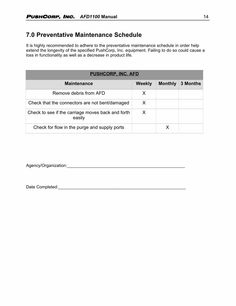
It is highly recommended to adhere to the preventative maintenance schedule in order help extend the longevity of the specified PushCorp, Inc. equipment. Failing to do so could cause a loss in functionality as well as a decrease in product life.
PUSHCORP, INC. AFD
Maintenance Weekly Monthly 3 Months
Remove debris from AFD X
Check that the connectors are not bent/damaged X
Check to see if the carriage moves back and fortheasily
X
Check for flow in the purge and supply ports X
Agency/Organization:_________________________________________________
Date Completed:_____________________________________________________