aerospace - july 2007 first article...ge inspection technologies. phased array. easy. portable. a...
TRANSCRIPT

A S P E C I A L S E C T I O N T O M A G A Z I N E
July 2007
AEROSPACE
End overtesting p. 4
Enhance First Article Inspection p. 8
Improve Your Audit Score p. 12
Source: The Boeing Co.
www.qualitymag.com
000-AS0707-cover.indd 1000-AS0707-cover.indd 1 6/20/07 9:22:17 AM6/20/07 9:22:17 AM

++--
Air GagingHigh Performance in Tough Environments
Mahr Federal - let us demonstrate our complete line of dimensional gages. Contact: Mahr Federal Inc., Providence, RI,
Phone 800-343-2050, Fax 401-784-3246, E-mail: [email protected], Internet: www.mahr.com
FORM MEASUREMENT
PRECISION LENGTH MEASUREMENT
PRECISION GAGES
SURFACEMEASUREMENT
OPTICAL MEASUREMENT
SNAPGAGES
AIRGAGING
More air gage display choices
New materials - high chrome alloys improve performance, shorten deliveries
Easy to use submicron inspection of critical diameters and tapers
Fast, special application solutions
•
•
•
•
Quality Quick Clicks 104 at qualitymag.com
QLT07074MahrAir.indd 1QLT07074MahrAir.indd 1 6/5/07 9:05:15 AM6/5/07 9:05:15 AM

GEInspection Technologies
Phased Arrayeasy. portable. a ordable.
The Phasor XSTM from GE
Whether you need to inspect scribe lines, landing gear, composites, welds, forgings or castings, the Phasor XS features all the capabilities you need.
It’s easy to operate, quick, incredibly rugged and portable weighing only 3.8 kilos (8.4 pounds). The Phasor XS o ers you all the advantages of real time phased array imaging technology plus conventional UT flaw detection for everyday ultrasonic inspections.
Lower cost transducers, speed and enhanced image-based reporting all translate into significantlyimproved inspection productivity.
Visit www.ge.com/phasorxs for more information.
Quality Quick Clicks 164 at qualitymag.com
QLT07074GEIn.indd 1QLT07074GEIn.indd 1 6/8/07 10:47:54 AM6/8/07 10:47:54 AM
2 Aerospace Special Section | July 2007 www.qualitymag.com
AEROSPACE | NEWSAEROSPACE | NEWS
NTS FULLERTON INCREASES AEROSPACE TEST CAPABILITIES FULLERTON, CA—National Technical Systems Inc., a provider of engineering services to a variety of industries, announces the addition of a high-power variable frequency pro-grammable power supply capability at their Fullerton, CA, test laboratory.
The AC/DC programmable power supply is capable of supplying 90 kilo-watts. This capability is necessary to
support RTCA/DO-160D/E, MIL-STD-704D/E and ABD0100.1.8 (Airbus) requirements.
“This signifi cant investment by NTS in the expanded power supply will allow us to provide clients with 400
and 800 hertz power,” says Dwight Moore, chief operating offi cer. “NTS Fullerton is now one of the few U.S. locations able to conduct this type of testing, which is vital for suppliers to Boeing and Airbus.”
PCB OPENS DIRECT SALES OFFICE IN UKDEPEW, NY—Sensor maker PCB Piezotronics Inc., a PCB Group Co., has established PCB Piezotronics Ltd., a
direct sales offi ce to serve customers in the United Kingdom. Located in Hitchin, Herts, PCB Piezotronics Ltd. will provide direct sales and customer support for all of PCB Piezotronics and IMI Sensors product lines, as well as focused specialty product and program support in the areas of aero-space, defense, test and measurement, and automotive applications.
Notes PCB Vice President of Sales and Marketing Kevin Cornacchio, “To meet the growing needs and requirements of customers in the United Kingdom and reinforce our
global commitment to total customer satisfaction, PCB has opened an addi-tional European sales offi ce, devoted specifi cally to customers in this geo-graphic region. PCB Ltd. will serve our customers with more direct support,
for both standard and specialty prod-ucts, as well as provide added benefi ts of improved service and deliveries.”
MEGGITT PLC FORMS SENSING DIVISIONBOURNEMOUTH, UNITED KINGDOM—Meggitt PLC, a global group of companies engaged in the design and manufacture of high-performance components and systems for aerospace, sensing and defense applications, announces the forma-tion of a new Meggitt Sensing Systems division. The division has been formed by merging the Meggitt Aerospace Systems and Meggitt Electronics groups into a single entity that aligns compa-nies in the sensing industry with related products, services and applications.
The new division will be led by Dr. Richard Greaves, a 30-year industry veteran and most recently the managing director of Meggitt Aerospace Systems.
“Meggitt Sensing Systems is a natu-ral and timely evolution of our sensing businesses that blends the unique capa-bilities and outstanding market posi-tions of our electronics and aerospace groups,” says Meggitt PLC CEO Terry Twigger. “By joining forces, they will create the pre-eminent group in this fi eld in the world with manufacturing and engineering capability on three continents, unparalleled technical resources, leading positions in our key markets and a much stronger market-ing capability.”
2007 WORLDWIDE AIRCRAFT MANUFACTURING INDUSTRY REPORT AVAILABLEDUBLIN, IRELAND—Research and Markets, a provider of international market research and market data, has announced the addition of 2007 Worldwide Aircraft Manufacturing Industry Report to their offerings. The report features 2007 current and 2008 forecast estimates on the size of the industry (sales, establishments, employment) for the 47 largest coun-tries. The report also includes industry defi nition, fi ve-year historical trends on industry sales, establishments and employment, and estimates on up to 10 sub-industries, including helicopters and gliders.
BOEING PROJECTS $2.8 TRILLION MARKET FOR NEW COMMERCIAL AIRPLANES LONDON—Boeing forecasts a $2.8 trillion market for new commercial airplanes over the next 20 years. These new airplanes will accommodate a forecasted 5% annual increase in passenger traffic, and a 6.1% annual increase in air cargo traffic.
The 2007 Current Market Outlook report, at http://www.boeing.com/commercial/cmo/, is Boeing’s world view of air travel over the next 20 years.
“Air travel is going to continue to grow, driven by economic growth, world trade, liberalization, and by the availability of new, more capable and more efficient air-planes,” says Boeing Commercial Airplanes Vice President, Marketing, Randy Tinseth. “This growth will occur in an environmentally responsible and accountable manner that addresses greenhouse gas reduction efforts with progressive new aircraft and increased operational efficiencies in the air transportation system.”
The Boeing outlook calls for a market of 28,600 new commercial airplanes (pas-senger and freighter) by 2026, with a much more balanced demand in aircraft by region over the forecast period.
On a delivery-dollar basis, the largest market is projected to be the Asia-Pacific region, with 36% of the $2.8 trillion total. North America will make up 26% of the delivery dollars, and Europe, Russia, and the CIS (Commonwealth of Independent States) will make up a total of 25%. Deliveries to airlines in Latin America, the Middle East, and Africa will represent the remaining 13% of the delivery dollars between 2007 and 2026.
002-AS0707news.indd 2002-AS0707news.indd 2 6/20/07 9:28:39 AM6/20/07 9:28:39 AM
Quality Quick Clicks 304 at qualitymag.com
QLT07074Leit.indd 1QLT07074Leit.indd 1 6/8/07 10:43:04 AM6/8/07 10:43:04 AM
4 Aerospace Special Section | July 2007 www.qualitymag.com
AEROSPACE | TESTING
Amajor cause of overtesting of spacecraft, aerospace and fl ight
hardware during random and swept sine vibration tests is associated with differences between the mechanical impedance of the shaker and mount-ing fi xture, and the standard practice of controlling the input acceleration to the frequency envelope of the fl ight data. The result is artifi cially high shaker forces and responses at the resonance frequencies of the test item. These high forces can damage expen-sive payloads.
To alleviate the problem of overtesting, it has become common practice to notch the input acceleration, in order to limit the responses in test to those predicted for launch into space. In simple terms, to notch means to reduce the amplitude of the shaker input near the resonant frequencies of the test item. However, this creates a paradox because there are multi-ple resonant points on complex structures and determining these resonant points on the structure is very much dependent on analysis, which the vibration test is sup-posed to validate.
Another challenge in vibration response testing is that it requires placing accelerometers on the test item at all critical locations, each hav-ing its own unique resonant response, and many locations can be inacces-sible. Since each location will have a different resonant frequency and exceed the control limits at some point during the test, it is often dif-fi cult to determine from which accel-erometer the test engineer should control the shaker.
Force Limited Vibration (FLV) test-ing is an alternative that improves the vibration testing approach based on measuring and limiting reaction force between shaker and test item. By using this method, the acceleration input to the test item is automatically notched at the equipment resonances by limiting shaker force values to those predicted for actual fl ight. Such notching, as it is described here, is based on the premise that mechani-cal impedance of payloads and the mounting structures are typically comparable for lightweight aerospace structures. FLV testing provides the test engineer with an opportunity to mirror structural response as seen during actual fl ight hardware mount-ing applications.
With force limited vibration testing, the force measurement signal is actu-ally used in the shaker’s feedback con-trol loop. This signal is compared to established force limits in the control-ler. At frequencies where the measured force exceeds the limit, the controller’s output signal (i.e., input signal to the shaker) is “notched” by reducing out-put amplitude. By reducing input to the shaker at these frequencies, reac-tion force between the test fi xture and structure is maintained within speci-fi ed limits.
Accelerometers also may be used in the control loop. They serve to limit shaker excitation with respect to acceleration at frequencies other than
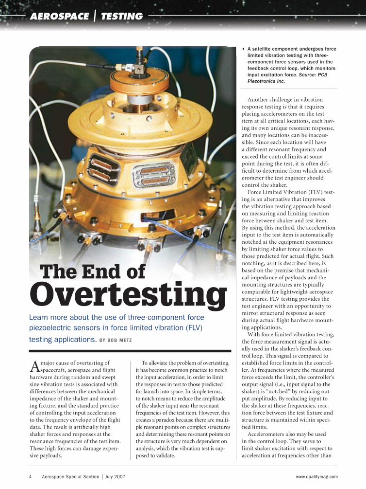
The End of OvertestingLearn more about the use of three-component force piezoelectric sensors in force limited vibration (FLV)
testing applications. BY BOB METZ
3 A satellite component undergoes force limited vibration testing with three-component force sensors used in the feedback control loop, which monitors input excitation force. Source: PCB Piezotronics Inc.
004-AS0707-101.indd 4004-AS0707-101.indd 4 6/20/07 9:42:25 AM6/20/07 9:42:25 AM
www.qualitymag.com July 2007 | Aerospace Special Section 5
resonances for which force limiting prevails. In order to accomplish this, the shaker control system must have “extremal control” capability. Extremal control is the ability to establish feed-back control with respect to the greater of several inputs, either force or accel-eration, as a function of frequency. Several modern day shaker controllers now have this capability.
Force control limits are typically pre-dicted using fi nite element analysis or actual launch data from prior fl ights, a safety margin added, and the resultant values are used to control the force input. So, instead of a control acceler-ometer, the test engineer uses piezo-electric force sensor control.
Multiple force sensors are mounted between the shaker and test item. The sensor signals must be summed through various other cables and multiple charge amplifi ers, which is both cumbersome and often results in signal drift if high impedance (insulation resistance) con-nectors become contaminated.
Quality Quick Clicks 360 at qualitymag.com
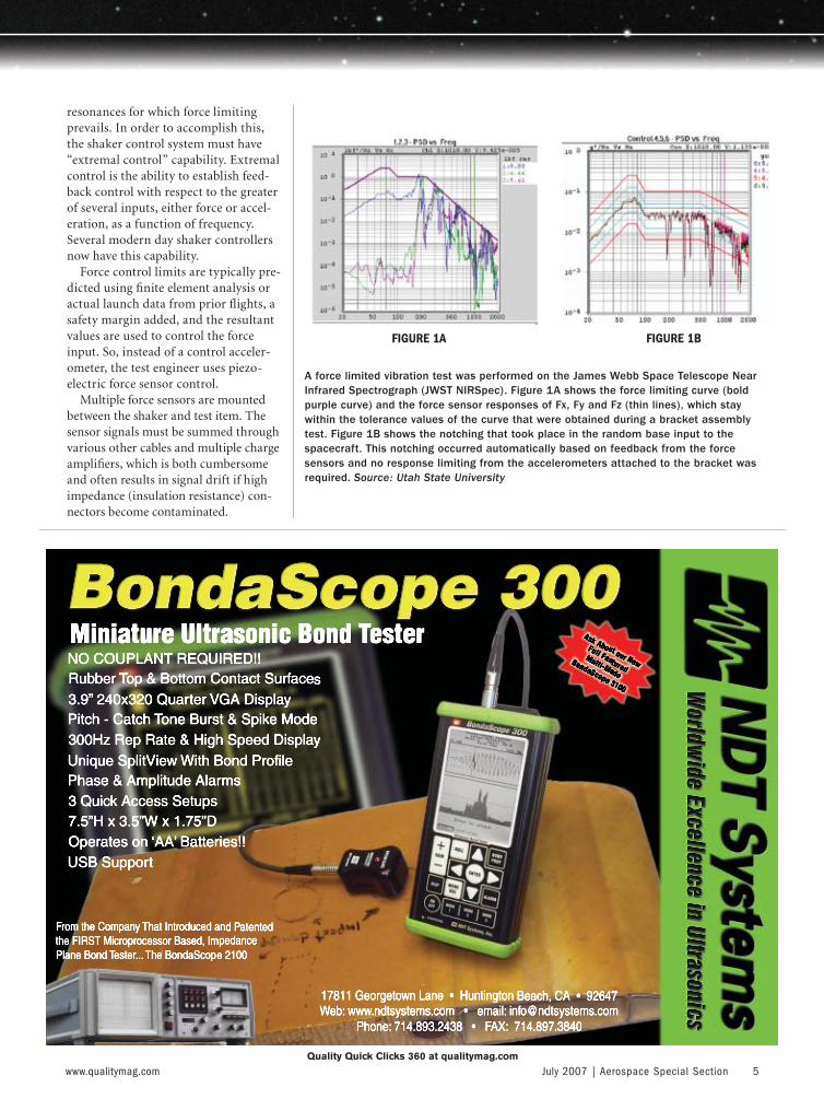
A force limited vibration test was performed on the James Webb Space Telescope Near Infrared Spectrograph (JWST NIRSpec). Figure 1A shows the force limiting curve (bold purple curve) and the force sensor responses of Fx, Fy and Fz (thin lines), which stay within the tolerance values of the curve that were obtained during a bracket assembly test. Figure 1B shows the notching that took place in the random base input to the spacecraft. This notching occurred automatically based on feedback from the force sensors and no response limiting from the accelerometers attached to the bracket was required. Source: Utah State University
FIGURE 1A FIGURE 1B
004-AS0707-101.indd 5004-AS0707-101.indd 5 6/20/07 9:42:27 AM6/20/07 9:42:27 AM

6 Aerospace Special Section | July 2007 www.qualitymag.com
AEROSPACE | TESTING
The three-component piezoelec-tric charge output force sensors can be mounted between the shaker and unit under test. The charge output must connect via multiple cables, which are routed and summed in special summing boxes, and then feed into multiple charge amplifiers. Also visible are accelerometers with built-in amplifier, placed at critical points on the structure, to monitor structural response.
The same ICP technology used for accelerometers is now available for these three-component force sensors. The benefits include easier cable management, hermetic sealing, simplified summing amplifiers and reduced overall labor cost to perform the testing.
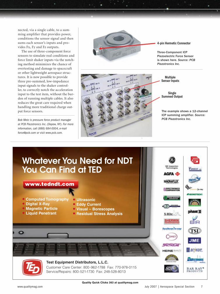
With the new three-component sensor, the most prominent change is the single, four-pin connector vs. the traditional three connectors on charge outputs styles. Each three-component force sensor may be con-
Top Quality Gage CalibrationISO17025 NVLAP Code 200605-0
Calibration Services
Mahr Federal - let us demonstrate our complete line of dimensional gages. Contact Mahr Federal Inc., Providence, RI
Phone: 800-343-2050, Fax: 401-784-3246 or E-mail: [email protected], Internet: www.mahr.com
+-
Dimensional
Gage Blocks Gage Calibration
Fast TurnaroundMaster Rings
Special Masters Competitive Prices
Quality Quick Clicks 361 at qualitymag.com Quality Quick Clicks 362 at qualitymag.com
JWST NIRSpec bracket assembly undergoing FLV test at the Space Dynamics Laboratory, Utah State University Research Foundation. Source: Utah State University
004-AS0707-101.indd 6004-AS0707-101.indd 6 6/20/07 9:42:29 AM6/20/07 9:42:29 AM
www.qualitymag.com July 2007 | Aerospace Special Section 7
nected, via a single cable, to a sum-ming amplifi er that provides power, conditions the sensor signal and then sums each sensor’s inputs and pro-vides Fx, Fy and Fz outputs.
The use of three-component force sensors to simulate real conditions and force limit shaker inputs via the notch-ing method minimizes the chance of overtesting and damage to spacecraft or other lightweight aerospace struc-tures. It is now possible to provide three pre-summed, low-impedance input signals to the shaker control-ler, to correctly notch the acceleration input to the test item, without the bur-den of running multiple cables. It also reduces the great care required when handling more traditional charge out-put force sensors.
Bob Metz is pressure force product manager at PCB Piezotronics Inc. (Depew, NY). For more information, call (888) 684-0004, e-mail [email protected] or visit www.pcb.com.
Test Equipment Distributors, L.L.C.Customer Care Center: 800-962-1788 Fax: 770-978-0115Service/Repairs: 800-521-1730 Fax: 248-528-8013
www.tedndt.com
Whatever You Need for NDT You Can Find at TED
• Computed Tomography• Digital X-Ray• Magnetic Particle• Liquid Penetrant
• Ultrasonic• Eddy Current• Visual – Borescopes• Residual Stress Analysis
Quality Quick Clicks 363 at qualitymag.com
Three-Component ICP Piezoelectric Force Sensor is shown here. Source: PCB Piezotronics Inc.
The example shows a 12-channel ICP summing amplifier. Source: PCB Piezotronics Inc.
004-AS0707-101.indd 7004-AS0707-101.indd 7 6/20/07 9:42:30 AM6/20/07 9:42:30 AM
4 AS 9102 has been the aerospace industry standard for first article inspections for more than five years.
4 Virtually all of the major aerospace primes and system inte-grators have adopted AS 9102 and require its application by their suppliers.
4 With its emphasis on accountability at the characteristic level and its consistency in both reporting methods and for-mat, AS 9102 application has helped enhance first article accuracy and reduce quality escapes at all levels of the supply chain.
TECH TIPS
8 Aerospace Special Section | July 2007 www.qualitymag.com
AEROSPACE | AS 9102
AS 9102 has been the aerospace industry standard for fi rst article
inspections for more than fi ve years. An aerospace supply chain quality engineer will likely have two comments about AS 9102. The fi rst will be that AS 9102 has brought much needed disci-pline and consistency to the fi rst article process. Then they will say that AS 9102 compliance requires considerable effort and commitment of resources.
Virtually all of the major aero-space primes and system integrators have adopted AS 9102 and require its application by their suppliers. With
its emphasis on accountability at the characteristic level and its consistency in both reporting methods and for-mat, AS 9102 application has helped enhance fi rst article accuracy and reduce quality escapes at all levels of the supply chain.
These “escapes”—which often mean that nonconforming hardware reaches customers—result in costly fi eld fi xes and warranty claims. The price tag for a single major escape can easily exceed $1 million. Given the stakes involved, the fi rst article process is viewed as an essential ingredient in the realization
of process capability relative to design intent during production.
While AS 9102 has clearly provided benefi ts to the industry, its widespread adoption and fl ow down have placed increased demands on suppliers’ tech-nical resources—particularly their quality and manufacturing engineers.
Shortly after the start of widespread AS 9102 adoption, suppliers offered anecdotal evidence of the volume of fi rst articles and the level of human resourc-es devoted to their completion. It was not unusual for them to cite numbers in excess of 40 hours to complete an AS 9102 compliant fi rst article inspec-tion. Moreover, the volume of fi rst article inspections at some suppliers was reported to be 100 or more annually. This combination of effort and volume represented a substantial drain on their limited technical resources.
The fi rst challenge was to better understand the validity of these numbers. If they were supported by objective data, there would be a clear indication of the need for better, more effi cient methods and tools for the AS 9102 process.
NEEDS ANALYSISIn 2004, the Air Force awarded a contract for the Electronic Industry-wide Network for Characteristics & Specifications (e-LINCS) to Renaissance Services. The e-LINCS program seeks to establish and implement universally accessible tools to f low detailed technical requirements to all levels of the aero-
Enhance
First Article Inspection
Advanced Tools bolster AS 9102 compliance. BY ROBERT MORRIS
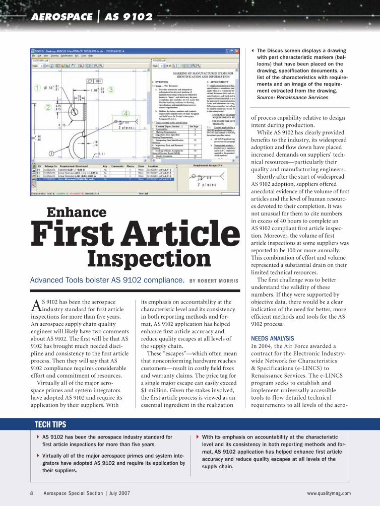
3 The Discus screen displays a drawing with part characteristic markers (bal-loons) that have been placed on the drawing, specification documents, a list of the characteristics with require-ments and an image of the require-ment extracted from the drawing. Source: Renaissance Services
008-AS0707-ft9102.indd 8008-AS0707-ft9102.indd 8 6/20/07 9:45:20 AM6/20/07 9:45:20 AM
www.qualitymag.com July 2007 | Aerospace Special Section 9
space supply chain—both commer-cial and military.
A key task in the early phases of e-LINCS was an extensive needs analysis.Its objective was to achieve a funda-mental understanding of how the fl ow, interpretation, verifi cation and man-agement of detailed technical require-ments took place in the supply chain. Part of this assessment was to better understand the existing fi rst article process and determine if actual data would support the anecdotal reports.
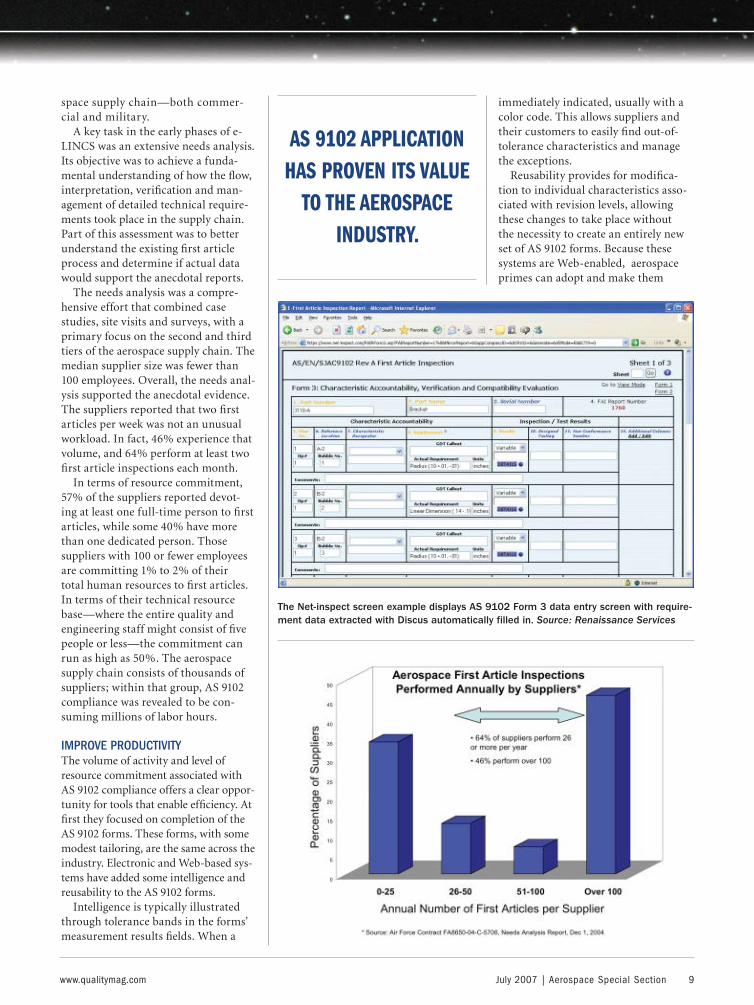
The needs analysis was a compre-hensive effort that combined case studies, site visits and surveys, with a primary focus on the second and third tiers of the aerospace supply chain. The median supplier size was fewer than 100 employees. Overall, the needs anal-ysis supported the anecdotal evidence. The suppliers reported that two fi rst articles per week was not an unusual workload. In fact, 46% experience that volume, and 64% perform at least two fi rst article inspections each month.
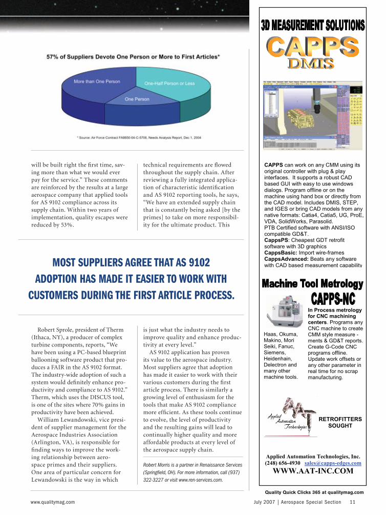
In terms of resource commitment, 57% of the suppliers reported devot-ing at least one full-time person to fi rst articles, while some 40% have more than one dedicated person. Those suppliers with 100 or fewer employees are committing 1% to 2% of their total human resources to fi rst articles. In terms of their technical resource base—where the entire quality and engineering staff might consist of fi ve people or less—the commitment can run as high as 50%. The aerospace supply chain consists of thousands of suppliers; within that group, AS 9102 compliance was revealed to be con-suming millions of labor hours.
IMPROVE PRODUCTIVITYThe volume of activity and level of resource commitment associated with AS 9102 compliance offers a clear oppor-tunity for tools that enable effi ciency. At fi rst they focused on completion of the AS 9102 forms. These forms, with some modest tailoring, are the same across the industry. Electronic and Web-based sys-tems have added some intelligence and reusability to the AS 9102 forms.
Intelligence is typically illustrated through tolerance bands in the forms’ measurement results fi elds. When a
value is entered, its pass/fail status is
immediately indicated, usually with a color code. This allows suppliers and their customers to easily fi nd out-of-tolerance characteristics and manage the exceptions.
Reusability provides for modifi ca-tion to individual characteristics asso-ciated with revision levels, allowing these changes to take place without the necessity to create an entirely new set of AS 9102 forms. Because these systems are Web-enabled, aerospace primes can adopt and make them
The Net-inspect screen example displays AS 9102 Form 3 data entry screen with require-ment data extracted with Discus automatically filled in. Source: Renaissance Services
AS 9102 APPLICATION HAS PROVEN ITS VALUE
TO THE AEROSPACE INDUSTRY.
008-AS0707-ft9102.indd 9008-AS0707-ft9102.indd 9 6/20/07 9:45:21 AM6/20/07 9:45:21 AM

10 Aerospace Special Section | July 2007 www.qualitymag.com
accessible to suppliers through their existing supply chain portals.
The most widely used of these systems—with more than 800 active suppliers—is offered by Net-Inspect. It includes AS 9102 compliant formats, Web-enabled access and features that enhance the effi ciency and accuracy of the fi rst article process. Application
is growing, with some 15,000 AS 9102 compliant fi rst article inspections com-pleted using this system.
Tools that enable more effi cient completion of AS 9102 forms assist the input, or back-end stage of the fi rst article process. The Air Force-spon-sored needs analysis, however, indi-cated that the most labor-intensive,
error-prone part of the process was during the front-end, characteristic identifi cation stage. At this point each dimension, geometry, note and speci-fi cation is given a unique identifi ca-tion number in the form of an indica-tor, or “balloon.”
The manual ballooning process involves a quality engineer, armed with a straightedge, a template and a pencil, poring over a drawing and painstakingly marking each charac-teristic to be included on the AS 9102 forms. These inputs are then manu-ally transcribed onto the forms. The shortcomings in this process are obvi-ous—manual intensity, opportunity for transcription errors and inability to effectively distribute or reuse the ballooned drawing.
Since completion of the needs analysis in late 2004, software tools that can enhance the characteristic identification process have been made available commercially. These tools allow suppliers to take an elec-tronic version of a paper drawing, such as a PDF or a CAD image, and rapidly and accurately identify, num-ber and organize each characteristic. They can then take these characteris-tics and seamlessly upload them to a variety of electronic AS 9102 formats, ranging from Excel to Net-Inspect. The most widely applied commer-cially available ballooning tools are DISCUS and BCT’s Inspector. Both offer electronic characteristic identi-fication and automated upload to the full range of AS 9102 formats. The quality engineers who have applied these tools report productivity gains as high as 70%.
PROMISING RESULTSAs companies adopt the tools, both their results and enthusiasm for the products grow. Ferco Tech (Franklin, OH) produces components for jet engines. Company chairman Joseph Murphy notes, “These tools provide a two-fold benefi t. First, they greatly enhance the productivity of our qual-ity engineers. But the real savings is in their error-proofi ng capabilities. If something escapes, it’s hard to calcu-late the cost. But the software gives you more assurance that products
Rugged, Reliable, Repeatable...For 75 Years!
• Applicable to Spur and Helical Gears!
• Gage the Part at the Machine!
PitchDiameter
MajorDiameter
Minor Diameter
Internal or External SplineMeasurement Made Easy!
Still using micrometers and pins metod?
Comtor Spline Gages make pitch diameter measurement quick, easy and accurate!
For all your gaging needs,Comtorgage it!
®
COMTOR SPLINE GAGESCOMTOR SPLINE GAGES
Comtorgage Corporation(Since 1928)
Ph: (401) 765-0900 Fax: (401) 765-2846www.comtorgage.com
Analog Dial or Digital Readout
Quality Quick Clicks 364 at qualitymag.com
AEROSPACE | AS 9102
008-AS0707-ft9102.indd 10008-AS0707-ft9102.indd 10 6/20/07 9:45:21 AM6/20/07 9:45:21 AM
www.qualitymag.com July 2007 | Aerospace Special Section 11
will be built right the fi rst time, sav-ing more than what we would ever pay for the service.” These comments are reinforced by the results at a large aerospace company that applied tools for AS 9102 compliance across its supply chain. Within two years of implementation, quality escapes were reduced by 53%.
Robert Sprole, president of Therm (Ithaca, NY), a producer of complex turbine components, reports, “We have been using a PC-based blueprint ballooning software product that pro-duces a FAIR in the AS 9102 format. The industry-wide adoption of such a system would defi nitely enhance pro-ductivity and compliance to AS 9102.” Therm, which uses the DISCUS tool, is one of the sites where 70% gains in productivity have been achieved.
William Lewandowski, vice presi-dent of supplier management for the Aerospace Industries Association (Arlington, VA), is responsible for fi nding ways to improve the work-ing relationship between aero-space primes and their suppliers. One area of particular concern for Lewandowski is the way in which
technical requirements are fl owed throughout the supply chain. After reviewing a fully integrated applica-tion of characteristic identifi cation and AS 9102 reporting tools, he says, “We have an extended supply chain that is constantly being asked [by the primes] to take on more responsibil-ity for the ultimate product. This
is just what the industry needs to improve quality and enhance produc-tivity at every level.”
AS 9102 application has proven its value to the aerospace industry. Most suppliers agree that adoption has made it easier to work with their various customers during the fi rst article process. There is similarly a growing level of enthusiasm for the tools that make AS 9102 compliance more effi cient. As these tools continue to evolve, the level of productivity and the resulting gains will lead to continually higher quality and more affordable products at every level of the aerospace supply chain.
Robert Morris is a partner in Renaissance Services (Springfield, OH). For more information, call (937) 322-3227 or visit www.ren-services.com.
Quality Quick Clicks 365 at qualitymag.com
MOST SUPPLIERS AGREE THAT AS 9102 ADOPTION HAS MADE IT EASIER TO WORK WITH
CUSTOMERS DURING THE FIRST ARTICLE PROCESS.
008-AS0707-ft9102.indd 11008-AS0707-ft9102.indd 11 6/20/07 9:45:22 AM6/20/07 9:45:22 AM
4 For any nonconformances (NCRs) that are found during an audit, points are deducted from the total possible score.
4 Key requirements, which are clauses of the AS 9100 standard that have been identified to be most critical, carry a greater point value.
4 An organization can receive a higher audit score by ensuring there are no NCRs in key requirement areas.
TECH TIPS
12 Aerospace Special Section | July 2007 www.qualitymag.com
AEROSPACE | AUDIT SCORE
From the pursuit of AS 9100 registra-tion to lean manufacturing, com-
panies are continually looking for the edge that will distinguish them from the competition. For AS 9100 registra-tion, one signifi cant advantage that is often overlooked is the audit score.
International certifi cation guidelines require that AS 9100 audits be scored. This score is posted in the Online Aerospace Supplier Information System (OASIS), which is used by the
aerospace community, particularly OEMs, to monitor supply chain audit performance. Many OEMs have mini-mum thresholds in terms of AS 9100 audit scores, and will look closely at a company’s score to help assess its qual-ity management system and ability to provide premiere products or services. The scores can be used to determine whether OEMs conduct on-site sup-plier assessments, or even whether con-tracts are awarded at all.
Organizations pursuing AS 9100 reg-istration can increase their probability of a positive audit score by learning the fac-tors that signifi cantly impact it. For each AS 9100 audit there is a total score to be achieved, which is based on applicable clauses of the standard. For instance, total possible scores would be different for organizations that are responsible for design vs. those that are not.
For any nonconformances (NCRs) that are found during an audit, points are deducted from the total possible score. Key requirements, which are clauses of the AS 9100 standard that have been identifi ed to be most criti-cal, carry a greater point value. Thus, by paying careful attention to key requirements, an organization can receive a higher audit score by ensur-ing there are no NCRs in these criti-cal areas.
So how does one know which claus-es have been identifi ed as key require-
The Impact of the
Audit ScoreThe audit score is one significant advantage that is often
overlooked in AS 9100 registration. BY ROGER RITTERBECK
Source: Pavel Jedlicka
012-AS0707-ftaudit.indd 12012-AS0707-ftaudit.indd 12 6/20/07 9:46:43 AM6/20/07 9:46:43 AM
www.qualitymag.com July 2007 | Aerospace Special Section 13
ments? In the AS 9100 checklist, AS 9101, there is a column identifi ed as key requirements, which showcases two designations for key requirements. Product-related key requirements are those that could have a direct impact on product conformity. These are identifi ed with a P. Management-relat-ed key requirements are those portions
of the system that industry has deter-mined need additional management focus and resources in order to meet the expectations of an aerospace qual-ity management system. Management-related key requirements are identifi ed with an M.
For sections of the standard where there are multiple sub-clauses, it also is important to distinguish where key requirements are identifi ed in the clause. Where the key requirement designation is at the very top of the clause, any sub-clause below would be considered key and would result in a signifi cant reduction in the audit score if NCRs were found here.
In other sections with multiple sub-clauses, key requirements may be iden-tifi ed only with certain sub-clauses. In this case only those sub-clauses with the designation would have a higher score impact.
Altogether there are 57 key require-ments identifi ed in AS 9101. These requirements could have a signifi cant impact on the fi nal outcome of an AS 9100 audit. Organizations pursuing AS 9100 registration should place addi-tional emphasis on these focus areas to maximize the results of their audit, and subsequently their audit score. The goal of achieving AS 9100 registration is not just to get a certifi cate, but also to implement an effective quality sys-tem that meets industry expectations and will increase the probability of
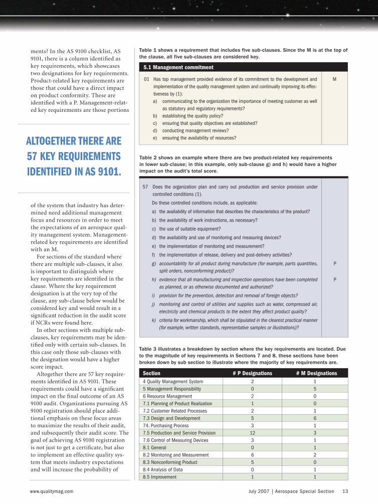
Table 1 shows a requirement that includes five sub-clauses. Since the M is at the top of the clause, all five sub-clauses are considered key.
5.1 Management commitment
01 Has top management provided evidence of its commitment to the development and implementation of the quality management system and continually improving its effec-tiveness by (1):a) communicating to the organization the importance of meeting customer as well
as statutory and regulatory requirements?b) establishing the quality policy?c) ensuring that quality objectives are established?d) conducting management reviews? e) ensuring the availability of resources?
M
Section # P Designations # M Designations 4 Quality Management System 2 15 Management Responsibility 0 56 Resource Management 2 07.1 Planning of Product Realization 1 07.2 Customer Related Processes 2 17.3 Design and Development 5 674. Purchasing Process 3 17.5 Production and Service Provision 12 37.6 Control of Measuring Devices 3 18.1 General 0 18.2 Monitoring and Measurement 6 28.3 Nonconforming Product 5 08.4 Analysis of Data 0 18.5 Improvement 1 1
57 Does the organization plan and carry out production and service provision under controlled conditions (1).
Do these controlled conditions include, as applicable:
a) the availability of information that describes the characteristics of the product?
b) the availability of work instructions, as necessary?
c) the use of suitable equipment?
d) the availability and use of monitoring and measuring devices?
e) the implementation of monitoring and measurement?
f) the implementation of release, delivery and post-delivery activities?
g) accountability for all product during manufacture (for example, parts quantities, split orders, nonconforming product)?
h) evidence that all manufacturing and inspection operations have been completed as planned, or as otherwise documented and authorized?
i) provision for the prevention, detection and removal of foreign objects?
j) monitoring and control of utilities and supplies such as water, compressed air, electricity and chemical products to the extent they affect product quality?
k) criteria for workmanship, which shall be stipulated in the clearest practical manner (for example, written standards, representative samples or illustrations)?
P
P
Table 2 shows an example where there are two product-related key requirements in lower sub-clause; in this example, only sub-clause g) and h) would have a higher impact on the audit’s total score.
Table 3 illustrates a breakdown by section where the key requirements are located. Due to the magnitude of key requirements in Sections 7 and 8, these sections have been broken down by sub section to illustrate where the majority of key requirements are.
ALTOGETHER THERE ARE 57 KEY REQUIREMENTS IDENTIFIED IN AS 9101.
012-AS0707-ftaudit.indd 13012-AS0707-ftaudit.indd 13 6/20/07 9:46:45 AM6/20/07 9:46:45 AM
14 Aerospace Special Section | July 2007 www.qualitymag.com
AEROSPACE | AUDIT SCORE
shipping good product and enhancing customer satisfaction.
So where are these 57 key require-ments located throughout AS 9100? A breakdown of the data reveals that 40
of the key requirements are product related—more than two-thirds of the total. Of those, 26 are in Section 7 alone. Every section of the standard contains at least one key requirement.
How do these 57 key requirements impact the score of AS 9100 audits? Within AS 9101 there is a scoring table used to calculate the score of AS 9100 audits. Point values have been allocated
by the aerospace industry group based on the importance of specifi c sub-sections. There are pre-determined point reductions for single and multi-ple nonconformities. If the nonconfor-
mity falls in a key requirement clause, the point reduction is greater. Table 4 illustrates an example of how drastic the point reduction can be.
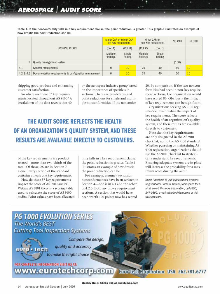
For example, assume two minor nonconformances have been written in Section 4—one is in 4.1 and the other in 4.2.3. Both are in key requirement sections. A section that would have been worth 100 points now has scored
20. By comparison, if the two noncon-formities had been in non-key require-ment sections, the organization would have scored 80. Obviously the impact of key requirements can be signifi cant.
Organizations seeking AS 9100 reg-istration must realize the impact of key requirements. The score refl ects the health of an organization’s quality system, and these results are available directly to customers.
Note that the key requirements are only designated in the AS 9101 checklist, not in the AS 9100 standard. Whether pursuing or maintaining AS 9100 registration, organizations should use the AS 9101 checklist to strategi-cally understand key requirements. Ensuring adequate systems are in place will increase the probability for a max-imum score during the audit.
Roger Ritterbeck is QMI Management Systems Registration’s (Toronto, Ontario) aerospace tech-nical expert. For more information, call (800) 247-0802, e-mail [email protected] or visit www.qmi.com.
SCORING CHART
Major CAR or minor CAR on Key requirement
Minor CAR on non Key requirement NO CAR RESULT
(Col. A) (Col. B) (Col. C) (Col. D)
Multiplefindings
Singlefinding
Multiplefindings
Singlefinding
4 Quality management system (100)
4.1 General requirements 0 10 25 40 50 10
4.2 & 4.3 Documentation requirements & configuration management 0 10 25 40 50 10
Table 4: If the nonconformity falls in a key requirement clause, the point reduction is greater. This graphic illustrates an example of how drastic the point reduction can be.
Quality Quick Clicks 366 at qualitymag.com
THE AUDIT SCORE REFLECTS THE HEALTH OF AN ORGANIZATION’S QUALITY SYSTEM, AND THESE RESULTS ARE AVAILABLE DIRECTLY TO CUSTOMERS.
012-AS0707-ftaudit.indd 14012-AS0707-ftaudit.indd 14 6/20/07 9:46:47 AM6/20/07 9:46:47 AM

Mahr Federal Inc. | 1144 Eddy Street | Providence, RI 02905 | E-mail: [email protected] | Tel: 1-800-343-2050 | Fax: 1-401-784-3246 | Web: www.mahr.com
FORM MEASUREMENT
PRECISION LENGTH MEASUREMENT
PRECISION GAGES
SURFACEMEASUREMENT
OPTICAL MEASUREMENT
SNAPGAGES
AIRGAGING
THE DIFFERENCE BETWEEN A GENTLE DESCENT
AND A NOSEDIVE IS A MERE 5 MICROINCH Ra IN
SURFACE ROUGHNESS.
Safety is everything – in aerospace as with everyday products. Error-free
production is essential. That’s why Mahr metrology is employed wherever
safety and high precision take top priority. Mahr crosses all borders.
+-
Quality Quick Clicks 302 at qualitymag.com
QLT07074MahrPlane.indd 1QLT07074MahrPlane.indd 1 6/6/07 9:06:38 AM6/6/07 9:06:38 AM

4 Boeing not only improved their accuracy by using a PDA-based calibration verification system from Mountz Inc., but also found a way to save money.
4 Mountz tools produced repeatability and reproducibility, and came close to Six Sigma values.
4 The system makes it easier for the technicians so they no longer have to worry about broken bolts from overtorquing or not applying enough torque.
BENEFITS
16 Aerospace Special Section | July 2007 www.qualitymag.com
AEROSPACE | CASE STUDY
In aerospace projects, there are no “do overs.” Even minor errors can
prove expensive or deadly. NASA’s $125 million Mars Climate Observer burned up in the Martian atmosphere when the manufacturer gave NASA English measurements for thrust, rather than metric units. A loose piece of foam cost seven shuttle astronauts their lives.
But careless mishaps also take place on the manufacturing fl oor. In
2003, for example, the U.S. National Oceanographic and Atmospheric Administration’s $233 million NOAA-N Prime weather satellite was severely damaged by falling three feet to a con-crete fl oor at Lockheed Martin’s satel-lite factory in Sunnyvale, CA. When one crew failed to document that it had removed two dozen bolts from a cart used to turn the satellite over, and the other crew failed to follow
procedures and check that the bolts were in place before moving the satel-lite, the end result was a $135 million repair bill.
Missing bolts, then, can certainly be a problem. But so are over- or under-torqued bolts and rivets. That’s why Six Sigma Black Belt Vu D. Pham of Boeing took on the task of improv-ing the accuracy of the torquing at his plant. Along the way, he not only improved the accuracy, but by using a PDA-based calibration verifi cation sys-tem from Mountz Inc. (San Jose, CA), also found a way to save the company a lot of money.
“We calculate that real savings for the fi rst year was a couple hundred thousand dollars,” says Pham, leader of engineering assurance at Boeing’s Satellite Development Center (SDC, El Segundo, CA). “This is just the raw savings of not sending tools out for calibration, and doesn’t include our savings on failures, repairs and person-nel costs.”
In December 2006, Boeing Space and Intelligence Systems (S&IS) was named as one of the two Gold-level recipients of the California Awards for Performance Excellence, the statewide equivalent of the Malcolm Baldrige Award. SDC is a part of S&IS.
CALIBRATION CONUNDRUMBoeing’s SDC is the world’s largest satellite manufacturer, with more than 200 commercial communication satellite launches since 1963, in addi-tion to military and weather satellites and spacecraft. The SDC’s 1-million-square-foot manufacturing facility has more than a dozen satellites under construction at any given time, pri-marily its 601 and 702 series of body-
Tightening UpTorque Standards
3 Boeing used Mountz BMX torque sen-sors as part of a torque verification sys-tem at the point of use. Source: Mountz
016-AS0707-CaseA.indd 16016-AS0707-CaseA.indd 16 6/20/07 9:47:58 AM6/20/07 9:47:58 AM
www.qualitymag.com July 2007 | Aerospace Special Section 17
stabilized communications models, as well as two lines of mobile communi-cations satellites. Pre-launch testing includes subjecting them to spin rates of 30 to 100 rpm, as well as vibra-tions and sound similar to what they would experience during launch—up to 50,000 pounds of force and 165 decibels. To test their ability to with-stand the rigors of space, satellites are placed in a thermal vacuum chamber and subjected to temperatures of -320 F to 250 F while powered up and with instruments operating.
The facility has received both the Software Engineering Institute’s Capability Maturity Model Integration (CMMI) Level 5 (Optimizing) certi-fi cation and AS 9100 certifi cation. AS 9100 is made up of the ISO 9001: 2000 standard with additional aerospace-specifi c requirements. Part of the SDC’s quality control program, for example, is complying with ANSI/NCSL Z540-1-1994 calibration standards.
“To meet those requirements, a torque verifi cation system has to include maintaining the history of each torque and the calibration data,” says Senior Calibration Engineer William K. Jinbo. “A quality control person would actually monitor the whole process of the bolt torquing, from the beginning of obtaining the wrench to the very end after the torquing is done. Then they would have to maintain the data and history of the torque.”
It also meant that each torque tool needed to be sent outside for calibra-tion—an expensive proposition consid-ering that SDC has 3,500 torque tools.
“I had a task to improve the quality of the torque tools that were caus-ing the overtorque,” says Pham. “To achieve this, we fi rst had to conduct a study of root causes using the stan-dard Six Sigma tools. This entailed looking at the people, systems, pro-cesses and methods, as well as the torque tools themselves.”
One thing that Pham and his team looked at was whether the gages were correctly calibrated or were the culprit. They conducted a study of repeatability and reproducibility and found that the tools were out of calibration, some by as much as a factor of 1.5 or 2, despite being sent to a third party for calibration.
Even though they were within tolerance, they were still subject to operator error. The tools were spring loaded and different operators would pull them different amounts after hearing the click. The solu-tion in place to fix this issue was to have an inspector listen for the click to ensure the component was not
under- or overtorqued. But even this was not consistent.
Then there was the issue of usability of the tools.
“With some of our tools, we could not change the torque values quickly enough so we used different tools for different torque values,” says Pham. This prompt-ed Boeing to look at other options.
Radiography Radioscopy Magnetic Particle Liquid Penetrant Ultrasonic
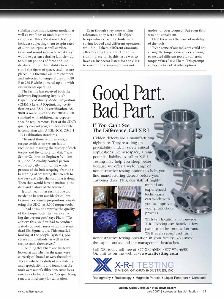
If You Can’t See The Difference, Call X-R-IHidden defects are a manufacturingnightmare. They’re a drag onprofitability and, in safety criticalapplications like aerospace, a hugepotential liability. A call to X-R-ITesting may help you sleep betterbecause we offer a wide range ofnondestructive testing options to help youfind manufacturing defects before your customer does. Plus, our staff of highly
trained andexperiencedtechnicianscan work withyou to improveyour productionprocess.
With ten locations nationwide, X-R-I Testing can handle a fewparts or entire production runs.We’ll even set-up and run a
nondestructive testing operation in your facility. You avoid the capital outlay and the management headaches.
Good Part.Bad Part.
Call XRI today toll-free at 877-XRI-4NDT (877-974-4638). Or, visit us on the web at www.xritesting.com
Quality Quick Clicks 367 at qualitymag.com
-AS -CaseA-AS -CaseA 9 A9 A
18 Aerospace Special Section | July 2007 www.qualitymag.com
AEROSPACE | CASE STUDY
THREE-PHASE IMPROVEMENT Based on the initial evaluation of problems with the existing torque system, Pham and his team began a three-phase project to address the issues. Phase one was to locate tools that were more accurate and consis-tent than what they had been using. They investigated several manu-facturers. Pham’s boss, Director of Engineering Quality Dan Pace, had worked with Mountz tools at a previ-ous company, and recommended that they be considered.
“We found that the Mountz tools could produce repeatability and repro-ducibility,” says Pham. “We tried them with different operators and different values, and they came very close to Six Sigma values.”
While that alone would have made a signifi cant improvement in opera-tions, that was not enough. That led to phase two—ensuring the tool was accurate every time, not just after annual calibrations.
“Even though the tool is good, what guarantee is there that if it is dropped it will still be calibrated?” says Pham. “So I challenged the
vendor to come up with a portable calibration system that we can bring to the point of use and test the tool before we use it. That way we will know if the values have shifted.”
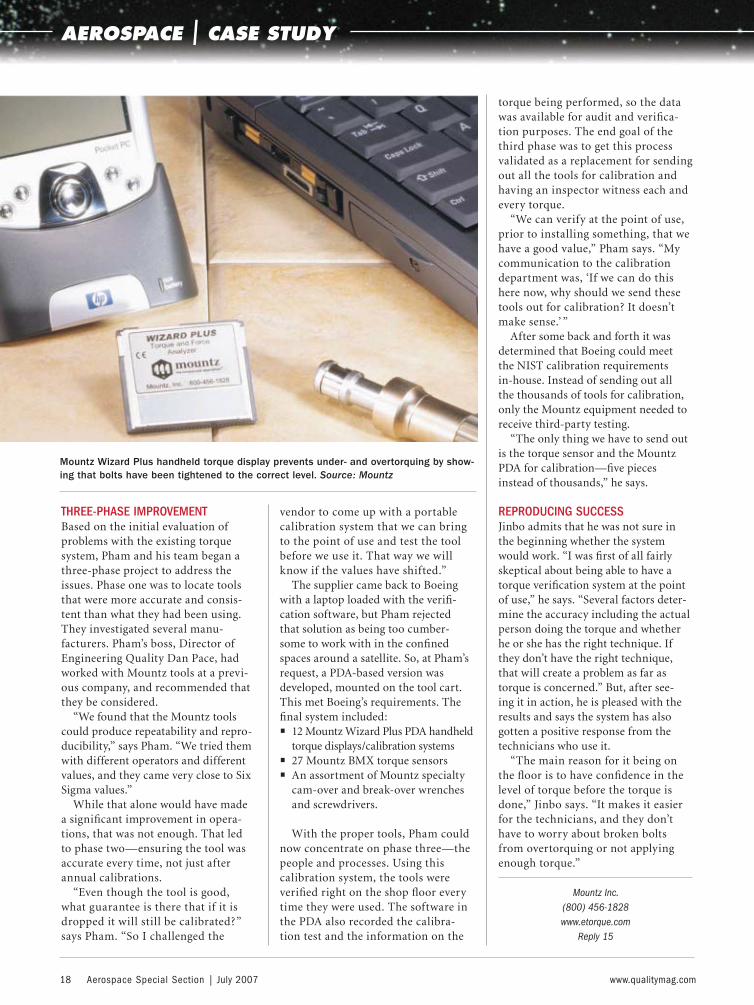
The supplier came back to Boeing with a laptop loaded with the verifi -cation software, but Pham rejected that solution as being too cumber-some to work with in the confi ned spaces around a satellite. So, at Pham’s request, a PDA-based version was developed, mounted on the tool cart. This met Boeing’s requirements. The fi nal system included:• 12 Mountz Wizard Plus PDA handheld
torque displays/calibration systems• 27 Mountz BMX torque sensors• An assortment of Mountz specialty
cam-over and break-over wrenches and screwdrivers.
With the proper tools, Pham could now concentrate on phase three—the people and processes. Using this calibration system, the tools were verifi ed right on the shop fl oor every time they were used. The software in the PDA also recorded the calibra-tion test and the information on the
torque being performed, so the data was available for audit and verifi ca-tion purposes. The end goal of the third phase was to get this process validated as a replacement for sending out all the tools for calibration and having an inspector witness each and every torque.
“We can verify at the point of use, prior to installing something, that we have a good value,” Pham says. “My communication to the calibration department was, ‘If we can do this here now, why should we send these tools out for calibration? It doesn’t make sense.’ ”
After some back and forth it was determined that Boeing could meet the NIST calibration requirements in-house. Instead of sending out all the thousands of tools for calibration, only the Mountz equipment needed to receive third-party testing.
“The only thing we have to send out is the torque sensor and the Mountz PDA for calibration—fi ve pieces instead of thousands,” he says.
REPRODUCING SUCCESS Jinbo admits that he was not sure in the beginning whether the system would work. “I was fi rst of all fairly skeptical about being able to have a torque verifi cation system at the point of use,” he says. “Several factors deter-mine the accuracy including the actual person doing the torque and whether he or she has the right technique. If they don’t have the right technique, that will create a problem as far as torque is concerned.” But, after see-ing it in action, he is pleased with the results and says the system has also gotten a positive response from the technicians who use it.
“The main reason for it being on the fl oor is to have confi dence in the level of torque before the torque is done,” Jinbo says. “It makes it easier for the technicians, and they don’t have to worry about broken bolts from overtorquing or not applying enough torque.”
Mountz Inc. (800) 456-1828www.etorque.com
Reply 15
Mountz Wizard Plus handheld torque display prevents under- and overtorquing by show-ing that bolts have been tightened to the correct level. Source: Mountz
016-AS0707-CaseA.indd 18016-AS0707-CaseA.indd 18 6/20/07 9:48:01 AM6/20/07 9:48:01 AM
www.qualitymag.com July 2007 | Aerospace Special Section 19
AEROSPACE | PRODUCTS
MACHINE TOOL CALIBRATION The MCV 4000 laser calibration system is designed for aerospace manufacturers and job shops that must maintain the high accuracy and repeatability of 3- and 5-axis machine tools and CMMs. The compact and lightweight system enables manual, automatic or on-the-fly data col-lection, as well as simultaneous linear and angular data collection with NIST-traceable laser accuracy. The laser head and mirrors are mounted on the machine tool, saving time and eliminating poten-tial problems. In turn, this eliminates the need for the tripod, allowing the system to be easily transported in two large hand-carried cases. Compensation for thermal growth caused by such envi-ronmental factors such as barometric pressure, air temperature and workpiece or material temperature is automatically addressed with standard sensors. OPTODYNE CORP.(310) 635-7481WWW.OPTODYNE.COMREPLY 642
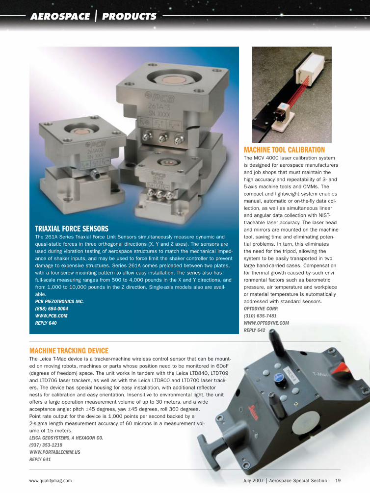
TRIAXIAL FORCE SENSORSThe 261A Series Triaxial Force Link Sensors simultaneously measure dynamic and quasi-static forces in three orthogonal directions (X, Y and Z axes). The sensors are used during vibration testing of aerospace structures to match the mechanical imped-ance of shaker inputs, and may be used to force limit the shaker controller to prevent damage to expensive structures. Series 261A comes preloaded between two plates, with a four-screw mounting pattern to allow easy installation. The series also has full-scale measuring ranges from 500 to 4,000 pounds in the X and Y directions, and from 1,000 to 10,000 pounds in the Z direction. Single-axis models also are avail-able.PCB PIEZOTRONICS INC.(888) 684-0004 WWW.PCB.COM REPLY 640
MACHINE TRACKING DEVICEThe Leica T-Mac device is a tracker-machine wireless control sensor that can be mount-ed on moving robots, machines or parts whose position need to be monitored in 6DoF (degrees of freedom) space. The unit works in tandem with the Leica LTD840, LTD709 and LTD706 laser trackers, as well as with the Leica LTD800 and LTD700 laser track-ers. The device has special housing for easy installation, with additional reflector nests for calibration and easy orientation. Insensitive to environmental light, the unit offers a large operation measurement volume of up to 30 meters, and a wide acceptance angle: pitch ±45 degrees, yaw ±45 degrees, roll 360 degrees. Point rate output for the device is 1,000 points per second backed by a 2-sigma length measurement accuracy of 60 microns in a measurement vol-ume of 15 meters. LEICA GEOSYSTEMS, A HEXAGON CO. (937) 353-1218WWW.PORTABLECMM.US REPLY 641
019-AS0707-prods.indd 19019-AS0707-prods.indd 19 6/20/07 9:49:07 AM6/20/07 9:49:07 AM

20 Aerospace Special Section | July 2007 www.qualitymag.com
AEROSPACE | PRODUCTS
CMMMaxos is a multi-axis optical CMM that can perform full inspection of machined aero-space blisks. The unit has a proprie-tary, patented non-contact probe that allows collection
of individual points at a rate of 70 per second. Like a touch-probe CMM, it col-lects individual points, but unlike a con-ventional CMM, it continues on its path at a high speed and without pausing. The system uses the conventional three axes of a CMM with two additional axes on its sensor along with two optional turntables resulting in up to seven axes in total. The unit has accuracy of ±2 micrometers on matte surfaces and ±10 micrometers on polished metal. It can achieve a point spacing resolution of 0.2 micrometer without pausing. Because it has no ball probe and measures a single point at a time, it is not limited by ball-offset geom-etry and can inspect radii of less than 0.2 millimeter. NVISION(248) 468-2525WWW.NVISION3D.COMREPLY 643
DATA ACQUISITION MODULESThe multifunctional, portable OMB-DAQ-3000 series of data acquisition mod-ules comes with comprehensive soft-ware support. The series can handle 16 analog input channels (operator-expand-able up to 64), up to four analog out-puts, 24 digital I/O, two timer outputs and four 32-bit counters. The series has a low-latency, highly deterministic control output mode that operates inde-pendent of the PC. In this mode, digital, analog and timer outputs can respond to analog, digital and counter inputs. The modules are CE compliant and are supplied with DaqView software, soft-ware drivers and a complete operator’s manual on CD ROM. Applications include the aerospace, automotive and manufacturing industries.OMEGA(514) 856-6928WWW.OMEGA.COMREPLY 644
ELECTROTHERMAL MECHANICAL TEST SYSTEMThe ETMT 8800 is suited for testing metals and other con-ductive materials in industries ranging from metal processing and production to advanced engineering, such as aerospace. Combined with a direct resistance heating system, it offers full reverse stress loading to 3 kilonewton and thermomechanical capabilities up to 1,500 C. The system is used for mea-suring mechanical and physical proper-ties and micro structural stability under thermal exposure. It can achieve fatigue loading rates from 20 newtons per sec-ond to 1,000 newtons per second and heating rates up to 200 C per second. The system is designed to study the thermo-mechanical fatigue properties of nickel-based superalloys, hard metals and lead-free solders. It also can be used to determine the resistivity, thermal expan-sion coefficients and phase transforma-tions in a variety of materials. INSTRON CORP. (800) 564-8378 WWW.INSTRON.COMREPLY 645
ADVERTISER PAGE REPLY NO. PHONE WEB ADDRESS
Applied Automation Technologies 11 365 (248) 656-4930 www.aat-inc.com
Centurion NDT 6 362 (630) 736-5500 www.centurionndt.com
Comtorgage Corp. 10 364 (401) 765-0900 www.comtorgage.com
Euro-Tech Corp. 14 366 (262) 781-6777 www.eurotechcorp.com
GE Inspection Technologies 1 164 (973) 448-0077 www.ge.com/phasorxs
Leitech-US Ltd. 3 304 (608) 271-9030 www.leitech.com
Mahr Federal Inc. IFC, 6, 15 104, 361, 302 (800) 343-2050 www.mahr.com
NDT Systems 5 360 (714) 893-2438 www.ndtsystems.com
Olympus NDT Inc. BC 141 (800) 225-8330 www.olympusNDT.com
SAI Global IBC 303 (800) 374-3818 www.saiglobal.com
Test Equipment Distributors LLC 7 363 (800) 962-1788 www.tedndt.com
XRI Testing Inc. 17 367 (877) XRI-4NDT www.xritesting.com
This index is provided as a reader service. The publisher assumes no liability for errors or omissions.
For more information, visit Quality Quick Clicks at qualitymag.com.AEROSPACE | AD INDEX
019-AS0707-prods.indd 20019-AS0707-prods.indd 20 6/20/07 9:49:08 AM6/20/07 9:49:08 AM

When it comes to AS9100/AS9110 training & performance improvement The sky is the limit ...
www.saiglobal.com
Our AS9100/AS9110 training curriculum shows you how to
implement the most current aerospace quality standards.
To reach new heights in process management and
performance visit www.saiglobal.com.
Quality Quick Clicks 303 at qualitymag.com
QLT07074SAI.indd 1QLT07074SAI.indd 1 6/8/07 10:58:37 AM6/8/07 10:58:37 AM

From the leader in phased array technology
For worldwide representation visit www.olympusNDT.com • [email protected]
One Button AwayConventional UT and Phased Array
Conventional UT A-Scan Phased Array Sectorial Scan
OmniScan® M Series Flaw DetectorLow-Cost, Entry-Level Phased Array
• Choose the 16:16M or 16:64M module
• Simple, user-friendly interface
• Real-time phased array imaging
• Code-compliant UT inspection
• Fully upgradable to advanced OmniScan modules with 100% trade-in credit: UT, PA, EC, or ECA
Quality Quick Clicks 141 at qualitymag.com
QLT07074Olym.indd 1QLT07074Olym.indd 1 6/14/07 9:27:33 AM6/14/07 9:27:33 AM