aerospace 96 m 0338743 0504055 t7b industries national
TRANSCRIPT

A I A I N A S NAS*<Lb75 96 M 0338743 0504055 T7b
Industries NATIONAL AEROSPACE STANDARD Aerospace
Association OCOPïRIGHT 1996 AEROSPACE INDUSTRIES ASSOCIATION OF AMERICA, INC. ALL RIGHTS RESERVED
I FED.SUPCL4SS
I CUSTODIAN
PROCUREMENT TITLE
1 .ScoDe and Classif ication.
THIRD ANGLE PROJECTION
CLASSIFICATION
1.1 Scope - This specification established the requirements for self-locking blind fasteners which are capable of being installed when only one side of an assembly is accessible.
1.2 Classification - This specification covers blind fasteners of the following classes:
Class 1. General Purpose (usable up to 450'F)
Class 2. High Temperature (usable up to 1200°F)
Class 3. Light Weight (usable up to 250°F)
Class 4 . Titanium (usable up to 600°F)
2. ApDlicable Documents.
2.1 The following publications of the issue in effect on the date of invitation for bids shall form a part of this specification to the extent specified herein.
2.1.1 SDecifications.
List of Current Sheets - Sheet No 1 2 3 4
-
1 25 26
f 43 -
Rev. No 4 3 4 2
i 2
N/C
1 N/C
Federal
QQ-P-3 5 Passivation Treatments For Corrosion- Resistant Steel
QQ-A-225/6 Aluminum Alloy 2024 Bar, Rod, and Wire; Rolled, Drawn or Cold Finished
QQ-A-22519 Aluminum Alloy 7075 Bar, Rod, Wire, and Special Shapes; Rolled, Drawn, or Cold Finished
QQ-A-250/13 Aluminum Alloy Alclad 7075, Plate and Sheet
QQ-P-416 Plating, Cadmium (Electrodeposited)
QQ-S-763 Steel Bars, Shapesfand Forgings, Corrosion Resisting
@ Completely Revised+
SPECIFICATION
NONE
Fastener - Blind Internally Threaded, External Sleeve
Self - Locking
I 1 NAS1675 SHEET 1 OF 43 Copyright Aerospace Industries Association of America Inc. Provided by IHS under license with AIA/NAS Licensee=Fuerza Aerea Argentina/5969982001
Not for Resale, 10/17/2008 09:55:51 MDTNo reproduction or networking permitted without license from IHS
--``,,,`,,`,``,,`````,,```,`,,-`-`,,`,,`,`,,`---

Aerospace A I A / N A S N A S r L b 7 5 96 D 0338743 0504056 902
I ndus t r ¡es NATIONAL AEROSPACE STANDARD Association Q COPYRIGHT 1996 AEROSPACE I'NDUSTRIBS ASSOCIATION OP AMERICA, INC. W RIGHTS RESBRVED
PPP-B-566
PPP-B-665
Military
MIL-S-5626
MIL-H-6088
MIL-S-6758
MIL-H-6875
MIL-A-8625
MIL-L-46010
MIL-H-81200
MIL-L-81329
Boxes, Folding, Paper board
Boxes, Paper board, Metal Edged and Components
Steel, Chrome-Molybdenum (4140) Bars, Rods, and Forging Stock (Aircraft Applications)
Heat Treatment of Aluminum Alloys
Steel, Chrome - Molybdenum (4130) Bars, and Reforging Stock (Aircraft Quality)
Heat Treatment of Steel, Process for
Anodic Coating, for Aluminum and Aluminum Alloys
Lubricant, Solid Film, Heat Cured, Corrosion Inhibiting
Heat Treatment of Titanium and Titanium Alloys
Lubricant, Solid Film, Extreme Environment, NATO Code Number S-1737 Metric
Copies of Federal Specifications and Standards and Military Specifications may be obtained upon application to the DODSSP- Subscription Service Desk, Building 4D, 700 Robins Av, Philadelphia, PA 19111-5094.
SAE
AMs 2770 Alloy Parts, Aluminum, Heat Treatment
AMs 2759/3 Heat Treatment of Precipitation Hardening Corrosion Resistant and Maraging Steel Parts
AMs 4911 Titanium Alloy Sheet, 6A1-4V
AMs 4928 Titanium Alloy Bars and Forgings, 6A1-4V
O Completely Revised NAS1 675 SHEET 2
I USE OF OR RELIANCE UPON THIS W U M E N T OR ANY NATIONAL AEROSPACE STANDARD IS ENTIRELY VOLUNTARY. AIA W E S NOT QUALIFY SUPPUERC OR CERTIFY CONFOR.MA!X-O~~MS PROOUCED UNDER NATIONAL AEROSPACE STANDARDS AIA MAKES NO REPRESENTATION OR CLAIM RESPECTING <II
Copyright Aerospace Industries Association of America Inc. Provided by IHS under license with AIA/NAS Licensee=Fuerza Aerea Argentina/5969982001
Not for Resale, 10/17/2008 09:55:51 MDTNo reproduction or networking permitted without license from IHS
--``,,,`,,`,``,,`````,,```,`,,-`-`,,`,,`,`,,`---

AMs 4967
AIA/NAS NASxLb75 76 m 0318743 0504057 847 m NATIONAL AEROSPACE STANDARD
OCOPYRIGHT 1996 ABROSPACB INDUSTRIBS ASSOCIATION OF AMBRICA. INC. ALL RIGHTS RBSBRVBD
Titanium Alloy Bars and Forgings, 6A1-4V
AMs 5639 Steel, Corrosion Resistant
AMs 5641
AMs 5731
Steel! Corrosion Resistant
Steel, Corrosion and Heat Resistant,
AMs 5734 Steel, Corrosion and Heat Resistant
AMs 5737 Steel, Corrosion and Heat Resistant
AMs 6322 Steel, Bars, Forgings and Rings
Copies of Aerospace Material Specifications (AMs) may be obtained from the Society of Automotive Engineers, Inc., 400 Commonwealth Drive, Warrendale, Pennsylvania 15096..00=
2.1.2 Standards.
Militam
MIL-STD-129 Marking for Shipment and Storage
MIL-STD-1312 Fastener, Test Methods
MIL-STD-6866 Inspection, Liquid Penetrant
American National Standards Institute
ANSI/ASME B46.1 Surface Texture
ANSI/ASQC 21.4 Sampling Procedures and Tables for Inspection by Attributes
ASTM E140 Standard Hardness Conversion Table f o r Metals
ASTM E1444
msc NAS672
Standard Practice for Magnetic Particle inspection
Plating - High Strength Steels Cadmium
0 Completely Revised SHEET 3
I USE OF OR RELIANCE UPON THIS COCUMENT OR ANY NATIONAL AEROSPACE STANDARD IS ENTIRELY VOLUNTARY. AIA WES NOT OUALIFY SUPPUERC OR CE--,~-C~NoRM4N_E-O~-iIEMS, PROg'JCEDYN~ER N4TLONAL AEROSPACE STANDARDS. AIA MAKES NO REPRESENTATION OR CLAIM RESPECTING I l i
Copyright Aerospace Industries Association of America Inc. Provided by IHS under license with AIA/NAS Licensee=Fuerza Aerea Argentina/5969982001
Not for Resale, 10/17/2008 09:55:51 MDTNo reproduction or networking permitted without license from IHS
--``,,,`,,`,``,,`````,,```,`,,-`-`,,`,,`,`,,`---

A I A / N A S NASS3675 96 0338743 0504058 785 D Aerospace Industries NATIONAL AEROSPACE STANDARD Association 0 COPYRIGHT 1996 ABROSPACB INDUSTRIBS A%OCIATION OF AMERICA, INC. ALL R I G W S RECERVSD
NAS10 6 9 Tension Fatigue Test - Procedure for Aeronautical Fasteners
NAS1669 Fastener - Blind, Internally Threaded, External Sleeve, General Purpose, Protruding Head, Self-Locking
NAS1670
NAS1671
NAS1 67 2
NAS1 6 7 3
NAS1674
NAS17 5 O
NAS1751
NAS1752
NAS1753
Fastener - Blind, Internally Threaded, External Sleeve, General Purpose, Flush Head, Self-locking
Fastener - Blind, Internally Threaded, External Sleeve, High Temperature, Protruding Head, Self-Locking
Fastener - Blind, Internally Threaded, External Sleeve, High Temperature, Flush Head, Self-Locking
Fastener - Blind, Internally Threaded, External Sleeve, Light Weight, Protruding Head, Self-Locking
Fastener - Blind, Internally Threaded, External Sleeve, Light Weight, Millable Head, Self-Locking
Fastener - Blind, Internally Threaded, External Sleeve, General Purpose, Flush Head, Self-Locking, 1/64 Inch Oversize
Fastener - Blind, Internally Threaded, External Sleeve, General Purpose, Protruding Head, Self-Locking, 1/64 Inch Oversize
Fastener - Blind, Internally Threaded, External Sleeve, High Temperature, Flush Head, Self-Locking, 1/64 Inch Oversize
Fastener - Blind, Internally Threaded, External Sleeve, High Temperature, Protruding Head, Self-Locking, 1/64 Inch Oversize
O Completely Revised 7 SHEET 4 I
USE OF OR RELIANCE UPON THIS DOCUMENT OR ANY NATIONAL AEROSPACE STANDARD IS ENTIRELY VOLUNTARY AIA DOES NOT OUALIFY SUPPUERC OR CER'i-C~NoRMAN_CE-O~~~oF_'TEMS PRCJJCCED!NDgR NATIONAL AEROSPACE STANOARDS AIA MAKEC NO REPRESENTATION OR CUIM RESPECTING f w
Copyright Aerospace Industries Association of America Inc. Provided by IHS under license with AIA/NAS Licensee=Fuerza Aerea Argentina/5969982001
Not for Resale, 10/17/2008 09:55:51 MDTNo reproduction or networking permitted without license from IHS
--``,,,`,,`,``,,`````,,```,`,,-`-`,,`,,`,`,,`---

~
~~~~ ~ ~ ~
Aerospace A I A / N A S N A S x 1 6 7 5 96 m 0338743 0504059 611 m Industries NATIONAL AEROSPACE STANDARD
0 1996 AEROCPACB INDUSTRIBS ASSOCIATION OF AMBRICA. INC. ALL RIGHTS RBSBRVBD Association
NAS1754 Fastener - Blind, Internally Threaded, External Sleeve, Light Weight, Millable Head, Self-Locking, 1/64 Inch Overs i z e
NAS1755
NAS5 17 O
NAS5171
NAS5270
NAS5271
Fastener - Blind, Internally Threaded, External Sleeve, Light Weight, Protruding Head, Self-Locking, 1/64 Inch Oversize
Fastener - Blind, Internally Threaded, External Sleeve, Titanium, Flush Head Self-Locking
Fastener - Blind, internally Threaded, External Sleeve, Titanium, Flush Head Self-Locking, 1/64 Inch Oversize
Fastener - Blind, Internally Threaded, External Sleeve, Titanium, Protruding Head, Self-Locking
Fastener - Blind, Internally Threaded, External Sleeve, Protruding Head, Titanium, Flush Head, Self-Locking, 1/64 Inch Oversize
Copies of NAS Specifications and Drawings may be obtained from Global Engineering Documents, 15 Inverness Way East, Englewood, Colorado 80112
3 . Reauirements. 3.1 shall be a product which has been tested according to and has passed the qualification tests specified herein. No change in dimensions, material or manufacturing procedures are permitted without requalification.
Qualification - The fasteners under this specification
3.2 three components defined as follows:
Comm3onents Parts - The fastener shall be constructed of
- Nut Consists of a head on the non-blind side and the shank of the fastener. The nut is internally threaded.
O Comp,ztely Revised NAS 1 675 SHEET 5 I
USE OF OR RELIANCE UPON THIS DOCUMENT OR ANY NATIONAL AEROSPACE STANDARD IS ENTIRELY VOLUNTARY AIA WES NOT WAUW SUPWERS OR
THE SUITABILITY OF ITEMS FOR ANY PARTICULAR APPLICATION. OR (21 THE EXISTENCE OF OR APPLICABILITY THERETO OF PATENT OR TRADEMARK RIGHTS CERTIFY CONFORMANCE OF ITEMS PRODUCED UNDER NATIONAL AEROSPACE STANDARDS. AIA MAKES NO REPRESENTATION OR CLAIM R E S P E ~ N G (1)
9
rl
u 01
m m
Fi
3 L n
N IC a>
m c 3 7 u1
t
r
3
0 2
a
Z
=. W
d <o rn
QI
3 7
c
u1 c 4 O J 4 > O U a a 4
Copyright Aerospace Industries Association of America Inc. Provided by IHS under license with AIA/NAS Licensee=Fuerza Aerea Argentina/5969982001
Not for Resale, 10/17/2008 09:55:51 MDTNo reproduction or networking permitted without license from IHS
--``,,,`,,`,``,,`````,,```,`,,-`-`,,`,,`,`,,`---

A I A / N A S NAS+Lb75 î b 0338743 05040b0 333 = Aerospace NATIONAL AEROSPACE STANDARD
,WpYRIGHT 1996 ABROCPACB IM>UCTRIBS ASSOCIATION OF AMBRICA. INC. ALL RIGHTS RBSBRVBû Industries Associat i o n
Screw Consists of a head on the blind side and an externally threaded shank.
Sleeve A malleable tubular device that expands over the end of the nut and causes the sheets of material to be drawn together.
NOTE: When a drawing specifies a discardable drive-nut to effect installation, it shall not be considered as a critical component and is not subject to the physical, metallurgical and traceability requirements set forth within this specification.
3.3 specified below:
Material - Material for fastener components shall be as
Class 1 Nut. Screw - Alloy Steel (UNS G41400) per MIL-S-5626, (UNS G87400) per AMs AMs6322 or (UNS G41300) per MIL-S-6758.
Sleeve - Corrosion resistant steel (UNS S30400) per QQ-S-763, AMs 5639 or (UNS S30323) per AMs 5641.
resistant steel (UNS S66286) with Chemical Composition per AMs 5731 or AMs 5734.
Class 2 Nut, Screw, Sleeve - Corrosion and Heat
Class 3 &JI& - Aluminum Alloy (UNS A970751 per QQ-A-225/9
Screw - Alloy steel (UNS G41400) per MIL-S-5626, (UNS G87400) per AMs 6322 or (UNS G41300) per MIL-S-6758.
Sleeve - Corrosion resistant steel..(UNS S30400) per QQ-S-763, AMs 5639 or (UNS S30323) per AMs 5641.
Nut and Screw - 6A1-4V Titanium (UNS R56400) per AMs 4928 or AMs 4967.
Class 4
Sleeve - A-286 Corrosion and Heat Resistant Steel (UNS S66286) with Chemical Composition per AMs 5731, or AMs 5734 or Corrosion Resistant Steel(UNS S30400) per QQ-S-763, AMs 5639 or (UNS S30323) per AMs 5641.
3.4 all dimensions shall conform to the applicable standard drawings. All dimensions are to be met after plating and finishing.
Desicm and Construction - The fastener configuration and
Copyright Aerospace Industries Association of America Inc. Provided by IHS under license with AIA/NAS Licensee=Fuerza Aerea Argentina/5969982001
Not for Resale, 10/17/2008 09:55:51 MDTNo reproduction or networking permitted without license from IHS
--``,,,`,,`,``,,`````,,```,`,,-`-`,,`,,`,`,,`---

Aerospace A I A / N A S N A S 1 1 6 7 5 '36 H 0318743 0 5 0 4 0 b 1 2 7 T
Industries NATIONAL AEROSPACE STANDARD Association OCOPYRIGHT 1996 AEROSPACE IM>USTRIBS ASSOCIATION OP AMERICA, INC. ALL RIGHTS RESERVED
3 . 4 . 1 Comi3onent Heads - The heads of all screws or nuts manufactured from alloy steel, titanium or corrosion and 'heat resistant steel shall be forged. Heads of aluminum nut ;nay be machined from heat treated stock or forged and subsequently heat treated.
3 .4 .2 Threads - The thread on the screw and in the nut shall be suitable for installation of the fastener and shall provide the installed fastener with the performance required by this specification. Threads shall be left-hand. Thread form, contour and dimensions are optional except that the minimum thread root radii for externally threaded screws shall be .002.
3i.4.2.1 Rolled Threads - The external thread on the screw shall be fully formed by a single thread rolling process.
3.4.3 Sheet Take-UD - The fastener sleeve shall be capable of engaging the lower surface of the lower sheet when the total sheet thickness is equal to the maximum grip of the fastener and the total gap between a l l sheets is .O31 of an inch when tested in accordance with Section 4 .
3 .5 Heat Treatment - Heat treatment of fasteners manufactured to this specification shall conform to Specifications MIL-H-81200, MIL-H-6875, MIL-H-6088, AMs- 2770, AMs 2759/3 as required to meet the strength requirements and metallurgical properties as defined herein. Aluminum components machined from heat treated stock shall have available mill certification that heat treatment was per MIL-H-6088. Aluminum components heat treated by the fastener manufacturer after heading or forging shall be heat treated to AMs 2770.
3 . 6 Protective Treatment - Protective treatment for fastener components shall be as specified below.
Class 1 Nut. Screw - Cadmium plated per QQ-P-416, Type II, Class 2 or NAS 672. Nuts may be deformed after plating to provide self locking feature. Sleeve - Passivate per QQ-P-35, Cadmium plate per QQ-P-416, Type I, Class 3 .
Class 2
Class 3
Nut, Screw and Sleeve - Passivate per QQ-P-35.
Nut - Anodize per MIL-A-8625, Type II. Clear on nominal diameters, green on oversize diameter fasteners.
O Completely Revised I NAS1675 SHEET 7 I
USE OF OR RELIANCE UPON THIS DOCUMENT OR ANY NATIONAL AEROSPACE STANDARD IS ENTIRELY VOLUNTARY. AIA WES NOT QUALIPT SUPPUERS OR CERTIPI CONFORMANCE OF ITEMS PRODUCED UNDER NATIONAL AEROSPACE STANDARDS. AIA MAKES NO REPRESENTATION OR CLAIM RESPECTING (i) THE SUITABILITY OF ITEMS FOR ANY PARTICULAR APPLICATION. OR fa THE EXISTENCE OF OR APPLICABILITY THERETO OF PATENT OR TRADEMARK RIGHTS
9
-I
0 a,
n n
a n E3
o> N b
7
W c 7 ln
a - 3
0 2
a
z
> w
w (D m 7
W c 3 7
w I- a n a -t
>
L Q U
Copyright Aerospace Industries Association of America Inc. Provided by IHS under license with AIA/NAS Licensee=Fuerza Aerea Argentina/5969982001
Not for Resale, 10/17/2008 09:55:51 MDTNo reproduction or networking permitted without license from IHS
--``,,,`,,`,``,,`````,,```,`,,-`-`,,`,,`,`,,`---

A I A / N A S NAS*3b75 î b m 0338743 0504062 LOb m Aerospace I _ Industries NATIONAL AEROSPACE STANDARD HT 1996 AEROSPACE INDUSTRIES ASSOCIATION OF AMBRICA. INC. ALL RIGHTS RESERVED
Screw - Cadmium plate per QQ-P-416, Class 2 or NAS 672.
Type II,
Sleeve - Passivate per QQ-P-35. Cadmium plat per QQ-P-416, Type I, Class 3.
Class 4 Nut & Screw - None
Sleeve - Passivate per QQ-P-35.
3.6.1 plated in accordance with QQ-P-416, shall, within four hours, be heated to a temperature of. 375'F k25'F and held at this temperature for a minimum of 23 hours.
Embrittlement Relief - Alloy steel components
3.7 part standard, the following lubricants may be applied by the fastener maufacturer to any or all components to facilitate driving :
Lubrication -Unless otherwise specified on the applicable
Solid Film Lube per MIL-L-46010, Type I or Type III Graphite Free D r y Film Lube per MIL-L-81329 Cetyl Alcohol lube. Paraffin W a x Carbo Wax
There shall be no deterioration of the lubricant adversely affecting fastener installation within two years after delivery of fasteners.
3.8 Mechanical ProDerties.
3.8.1. Double Shear Strencrth - The double shear strength shall be as specified in Table I when tested in accordance with Section 4.6.2.
3.8.2 joints as defined in Paragraph 4.6.3 shall have the
Sincrle Shear LaD Joint Strenath - Single shear lap
strength shown in Table V when tested in accordance with Section 4.6.3.
3.8.3 Tensile Strenath - The tensile strength shall be as specified in Table I when tested in accordance with Section 4.6.4. The fastener tensile strength as listed in Table I is defined as the load level at which the slope of the fastener load-deflection curve becomes zero for the first time. This is the "first peak tension strength" of the fastener, not the ultimate or breaking strength of the fastener which may follow some component failure within the fastener on the second or third peaking of the load.
O Completely Revised NAS 1 675 SHEET 8 I
USE OF OR RELIANCE UPON THIS DOCUMENT OR ANY NATIONAL AEROSPACE STANDARD IS ENTIRELY VOLUNTARY. AIA 0013 NOT WALIFY SUPPUERS OR CERTIFY CONFORMANCE OF ITEMS PRODUCED UNDER NATIONAL AEROSPACE STANDARDS. AIA MAKEC NO REPRESENTATION OR CLAIM RECPECTING ( I ) THE SUITABILITY OF ITEMS FOR ANY PARTICULAR APPLICATION. OR 121 THE EXISTENCE OF OR APPLICABILITY THERETO OF PATENT ORTRADEMARK RIGHTS Copyright Aerospace Industries Association of America Inc.
Provided by IHS under license with AIA/NAS Licensee=Fuerza Aerea Argentina/5969982001 Not for Resale, 10/17/2008 09:55:51 MDTNo reproduction or networking permitted without license from IHS
--``,,,`,,`,``,,`````,,```,`,,-`-`,,`,,`,`,,`---

Aerospace A I A / N A S NASS1675 96 9 0338743 0504063 042
Industries NATIONAL AEROSPACE STANDARD Association COPYRIGHT 1996 AmOSPACE INDUSTRIES ASCOCIATION OF AHBRICA, INC. ALL RIGHTS RESERVED
UV> E E
COE au) 2 , $ 2 a + o u Z E a 4 2 0 2 z z g UJW I-25 z5= P U Z Lye3 3WI 5 x 2
w2: 2 - 0 w o w =zz Z * O $9 50’
+ W u >
o< e m g
23: 2 x 0 = < U CUJY
TABLE I STRENGTH REOUIREMENTS
a cn cn rl
u al cri rn
ei Cu h o,
3.8.4 C l a m p U D Pre-Load - The fastener shall be capable of a tension pre-load of 20% of the tensile strength as specified in Table I when tested in accordance with Section 4.6 .5 .
For Class 4 onlv: The maximum pre-load shall not exceed
or nut when tested per Paragraph 4.6.4.2.
3.8.5
installed and tested as specified in Section 4.6.7
r
o C
7 Lo - 8 z
80% of the actual ultimate failure load of either the screw 0 i w a
.Q Ul o, Vibration Endurance - Fasteners shall be capable of
withstanding vibration endurance requirements when 7-
m c a -J
W l- U o ...I 4 > a
O Completely Revised ‘ 4
n o
NAS1 675 SHEET 9
USE OF OR RELIANCaUPON THIS DOCUMENT OR ANY NATIONAL AEROSPACE STANDARD IS ENTIRELY VOLUNTARY AIA WES NOT QUALIFY SUPPUERC OR CERTinC~NORMAN_CE-O~~~EMS PROOUCED UNDER NATIONAL AEROSPACE STANDARDS AIA MAKES NO RFPRFSFNTATION n R Pl A I U ~ C C ~ C ~ I u ~ 111
Double Shear Strength (Min. ) Pounds
Tensile Strength ( M i n . ) Founds
Copyright Aerospace Industries Association of America Inc. Provided by IHS under license with AIA/NAS Licensee=Fuerza Aerea Argentina/5969982001
Not for Resale, 10/17/2008 09:55:51 MDTNo reproduction or networking permitted without license from IHS
--``,,,`,,`,``,,`````,,```,`,,-`-`,,`,,`,`,,`---

I
P i3 ä
I
W V I
E?
A I A / N A S N A S + L b 7 5 96 H 03387q3 0504064 T ô 9 NATIONAL AEROSPACE STANDARD
Association Q COPYRIGHT 1996 AEROSPACE INDWTRIBS ASSOCIATION OP AMERICA. INC. ALL RIGHTS RESERVED
3.8.6 Tension-Tension Fatime Life - The fasteners shall be capable of sustaining an average fatigue life of 30,000 cycles and a minimum fatigue life of 15,000 cycles in tension-tension fatigue when tested in accordance with Section 4.6.8.
3.8.7 within the hardness ranges of HRc 39-43, R30N 58.5-62 or R45N 42-46.5 and all heat resistant steel nuts and screws shall be within the hardness range of HRc 30-45 when tested in accordance with Section 4.6.9.
Hardness - All alloy steel components shall be
3.9 Metalluraical ProDerties.
3.9.1 Surface Effects - The alloy steel components shall show no visual evidence of carbon enrichment, nitrogenization or other case hardening and there shall be no complete decarburization. Partial decarburization shall not extend more than .O03 inch from the surface of heads, head to shank fillets, shanks or threads when examined as specified in Paragraph 4.6.10.
3.9.2 Discontinuities - Fastener components shall be examined as specified in Section 4. Any components having discontinuities equal to or exceeding the following limitations shall be rejected. Care must be exercised to avoid confusing cracks, as defined herein, with other discontinuities.
3.9.2.1 Cracks - Fastener components shall be free of cracks in any direction or location. A crack is defined as a clean crystalline break passing through the grain or grain boundary with or without the inclusion of foreign elements.
3.9.2.2 possess laps and seams, except in locations specified in 3.9.2.3 and 3.9.2.4. The depth shall not exceed the amounts specified in Table II. A lap is a surface defect caused by folding over hot metal fine or sharp corners and then rolling or forging them into the surface; but not welding them. A seam is a lap that has been closed but not welded.
LaDs and Seams - Fastener components may
O Completely Revised NAS1675 SHEET 10
I USE OF OR RELIANCE U W N THIS DOCUMENT OR ANY NATIONAL AEROSPACE STANDARD IS ENTIRELY VOLUNTARY. AIA DOES NOT OUALIM SUPPUERS OR ~ E ~ ~ ~ ~ - ~ N O ~ ~ A ~ ~ E - o ~ ~ ~ ~ ~ s . PfltFUCJDgNDER NATIONAL AEROSPACE STANDARDS. AIA MAKES NO REPRESENTATION OR CI AIM ~ C C D C ~ I N I I mi
Copyright Aerospace Industries Association of America Inc. Provided by IHS under license with AIA/NAS Licensee=Fuerza Aerea Argentina/5969982001
Not for Resale, 10/17/2008 09:55:51 MDTNo reproduction or networking permitted without license from IHS
--``,,,`,,`,``,,`````,,```,`,,-`-`,,`,,`,`,,`---
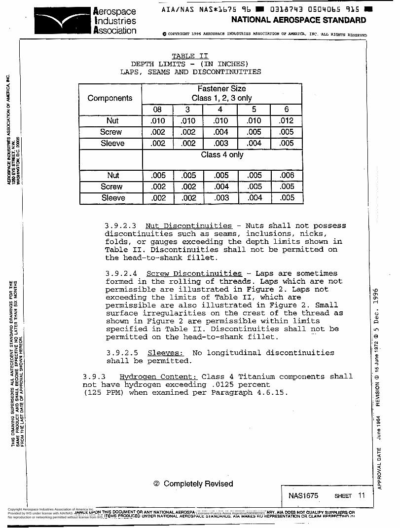
TABLE II DEPTH LIMITS - (IN INCHES)
Components Fastener Size
Class 1,2.3 onlv
Nut Screw Sleeve
.~
08 3 4 5 6
.o02 .o02 .O04 .O05 .O05
.o02 .o02 .O03 ,004 .O05
.o10 .o10 .o1 o .o1 o .o1 2
-.
3.9.2.3 discontinuities such as seams, inclusions, nicks, folds, or gauges exceeding the depth limits shown in Table II. Discontinuities shall not be permitted on the head-to-shank fillet.
Nut Discontinuities - Nuts shall not possess
Nut Screw Sleeve
3.9.2.4 formed in the rolling of threads. Laps which are not permissible are illustrated in Figure 2. Laps not exceeding the limits of Table II, which are permissible are also illustrated in Figure 2. surface irregularities on the crest of the thread as shown in Figure 2 are permissible within limits specified in Table II. Discontinuities shall not be
Screw Discontinuities - Laps are sometimes
Small
permitted on the head-to-shank fillet. .. .
Class 4 only
.O05 .O05 .O05 .O05 .O06
.o02 .o02 .O04 .O05 .O05
.o02 .o02 .O03 .O04 .O05
3.9.2.5 Sleeves: No longitudinal discontinuities shall be permitted.
3.9.3 not have hydrogen exceeding .O125 percent (125 PPM) when examined per Paragraph 4.6.15.
Hvdroqen Content: Class 4 Titanium components shall
O Completely Revised NAS1675 SHEET 11
I USE OF OR RELIANCE UPON THIS DOCUMENT OR ANY NATIONAL AEROSPACE STANDARD IS ENTIRELY VOLUNTARY. AIA DOES NOT QUALIPI SUPPUERC OR CER- .~-CONOR-MAN~E-O~~~EMS, PROFl!CED UNDER NATIONAL AEROSPACE STANDARDS. AIA MAKES NO REPRESENTATION OR CLAIM RFSPFCTîNn f i \
o
i
u al 3 r )
B c n .
n n
I-
al
7 ul a
r
3
0 2
2 u1 U
d <D o> r
m c z
-2
w I- U P -I U > B n n <
Copyright Aerospace Industries Association of America Inc. Provided by IHS under license with AIA/NAS Licensee=Fuerza Aerea Argentina/5969982001
Not for Resale, 10/17/2008 09:55:51 MDTNo reproduction or networking permitted without license from IHS
--``,,,`,,`,``,,`````,,```,`,,-`-`,,`,,`,`,,`---

Aerospace A I A / N A S NAS*:Lb75 96 0338743 05040bb 85L.m I ndust r ¡es NATIONAL AEROSPACE STANDARD
0 COPYRIGHT 1996 ABROSPACE INDUSTRIES ASSOCIATION OF AMERICA, INC. ALL RIGHTS RESERVED Association
3 . 9 . 4 Metallurgical Condition - (Class 4 only): Microstructure of titanium components shall be free from indication that it has been heated to a temperature above Beta transus without subsequently receiving a significant mechanical reduction in the Alpha-beta temperature range. Slight overheating on the non-bearing surfaces of the nut and corebolt heads is permissible providing measurement perpendicular to the surface does not exceed two times the value specified for the applicable component in Table II. (Structure of 6A1-4V alloys which has outlines of equiaxial prior all Beta grains and no primary Alpha is considered overheated. )
Titanium components shall not show evidence of Alpha case in excess of the limitations of Figure 1 when examined as specified in Paragraph 4.6.14
.. .
LBRE,, NECK GROOVEA
A No Alpha Case Permitted A Alpha Case Permitted to a M a x Depth of .O02
Fiuure 1 Alpha Case Limitations
O Completely Revised NAS1675 SHEET 12
USE OF OR RELIANCE U W N THIS DOCUMENT OR ANY NATIONAL AEROSPACE STANDARD IS ENTIRELY VOLUNTARY. AIA WES NOT OUALIFT SUPPUERC OR CERTi.~-o"?RM^",CE~Ms, ~ ~ ~ ~ ~ c E ~ $ N ~ ~ ~ NAT!oNAL AEROSPACE STANDARDS. AIA MAKES NO REPRESENTATION OR CLAIM RFSLF~!TINC 131
Copyright Aerospace Industries Association of America Inc. Provided by IHS under license with AIA/NAS Licensee=Fuerza Aerea Argentina/5969982001
Not for Resale, 10/17/2008 09:55:51 MDTNo reproduction or networking permitted without license from IHS
--``,,,`,,`,``,,`````,,```,`,,-`-`,,`,,`,`,,`---

A I A / N A S NAS*3675 96 0338743 0504067 798 Aerospace I ndust r ¡es NATIONAL AEROSPACE STANDARD Association 0 COPYRIGHT 1996 ABROSPACB INDUSTRIES ASSOCIATION OP AMERICA, INC. ALL RIGHTS RBSERVED
3.10 installed and examined in accordance with Section 4.
3.11 be permanently and legibly marked as specified on the applicable NAS drawing.
Installation - Fasteners shall drive consistently when
Identification of Product - Each fastener assembly shall
3.12 in Table VI11 when tested in accordance with Section 4.6.13
Lockins Features - Prevailing torque shall be as specified
Laps and seams Pressure Side not perm i ssi ble
Major Diameter
-- Pitch Diameter
Minor Diameter
Permissible surf ace Irregular i t i es
Major Diameter
Pitch Diameter
- Minor Dlameter .---
Non-pressure side
Major Diameter
Pitch Diameter
Minor Diameter
--
--
Perm iss i b Le laps and seams
Figure 2 Permissible and Non-Permissible L a p s ,
Seams and Surface Irregularities
O Completely Revised NAS1675 SHEET 13
Copyright Aerospace Industries Association of America Inc. Provided by IHS under license with AIA/NAS Licensee=Fuerza Aerea Argentina/5969982001
Not for Resale, 10/17/2008 09:55:51 MDTNo reproduction or networking permitted without license from IHS
--``,,,`,,`,``,,`````,,```,`,,-`-`,,`,,`,`,,`---

AIA/NAS NASxLb75 96 E 0318743 0504068 624 E Aerospace
Association Industries NATIONAL AEROSPACE STANDARD
0 COPYRIGHT 1996 AEROSPACE INL'USTRIES ASSOCIATION OF AMBRICA, INC. ALL RIGIfPS RESERVED
4. OUALITY ASSURANCE PROVISIONS.
4.1 ResDonsibilitv for Inmection - The supplier is responsible for the performance of all inspection requirements as specified herein. Except as otherwise specified the supplier may utilize his own or any other adequate facilities. Inspection records of the examination and tests shall be maintained and shall be available to the buyer on request. The buyer reserves the right to perform any of the inspections set forth in this specification where such inspections are deemed necessary to insure compliance with the prescribed requirements.
4.2 Lot Definition.
4.2.1 lot is a quantity of blind fastener components (e.g., screw, nuts or sleeves) of identical configuration fabricated from the same heat of material by the same procedures, heat treated and processed as a controlled batch.
ComDonent Production Lot - A component production
4.2.2 Assemblv Production Lot - A n assembly production lot is a quantity of blind fastener assemblies in which each of the three components represents a single component production lot. The producer must maintain a record defining the component production lots which make up each assembly production lot.
4.2.3 InsDection Lot - An inspection lot is that portion of an assembly lot which is procured as one purchase order item. An inspection lot may be received in parts through more than one shipment. Records shall be maintained for a minimum period of five(5) years after completion of fabrication.
4.3 and testing of blind fasteners shall be classified as follows:
Classification of Examination and Tests - The inspection
a. Initial Qualification (4.4) b. Quality Conformance Inspection ( 4 . 5 )
4.4 Initial Oualification - Initial qualification shall consist of all the examinations and tests defined in Paragraph 4.6. Initial qualification must be accomplished f o r each diameter and class of blind fastener qualified. Qualification on the flush heád configuration constitutes qualification of the equivalent protruding head configuration except for tensile strength and tension-tension fatigue testing which shall be performed on both head styles.
4.4.1 sizes are as defined in Table III.
Sarmlina Instructions - Initial qualification sample
Copyright Aerospace Industries Association of America Inc. Provided by IHS under license with AIA/NAS Licensee=Fuerza Aerea Argentina/5969982001
Not for Resale, 10/17/2008 09:55:51 MDTNo reproduction or networking permitted without license from IHS
--``,,,`,,`,``,,`````,,```,`,,-`-`,,`,,`,`,,`---

A I A / N A S NASu3675 96 m 0338743 05040bî 5 6 0 m Aerospace I I ndust r ¡es NATIONAL AEROSPACE STANDARD - dPYRIGHT 1996 AEROSPACE INDUSTRIES ASSOCIATION OP AMERICA, INC. ALL RIGHTS RESERVED
I TABLE III
SAMPLING FOR OUALJFICATION
TEST No. of Samples Test Method
Class 1,2 ,3 Class 4
Dimension Examination 5 5 4 . 6 . 1
Discontinuities
Double Shear 5 5 4 .6 .2
Single Shear Lap Joint 10 10 4.6 .3
All Samples 4 . 6 . 1 1 2 3 1
1 Tensile Strength, 5
5 I- 5 Clamp-Up Preload Sheet Take-up
1 0 4 .6 .4
1 0 4 .6 .5 5 4 .6 .6
Vibration Endurance 16 (12) 16 ( 1 2 ) 4.6.7
Tension-Tension Fatigue 5 5 4.6.8
5 4.6.9 Hardness
Surface Effects 5 4.6 .10
Installation - Group A Group B Group C
10 o 1 0 o 100
20 20 20
4 .6 .12 4 .6 .12 4 .6 .12
Locking Zeature-Prevailing Torque
.. .
4 .6 .13 5 5
Hydrogen Content 1 4.6 .15
Metallurgical Condition 2 4 .6 .14
*When two tests are shown bracketed together, the sample may be used for both tests.
O Completely Revised a
I NAS1675 SHEET 15 I I
USE OF OR RELIANCEUWN THIS WCUMENT OR ANY NATIONAL AEROSPACE STANDARD IS ENTIRELY VOWNTARY. AIA DOES NOT OUALIFY CUPPUERS OR CERTIFY CONFORMANCE OF-IEMS PRODUCED UNDER NATIONAL AEROSPACE STANDARDS. AIA MAKES NO REPRESENTAllON OR CI A I M ~CCDCCTINC í i i
Copyright Aerospace Industries Association of America Inc. Provided by IHS under license with AIA/NAS Licensee=Fuerza Aerea Argentina/5969982001
Not for Resale, 10/17/2008 09:55:51 MDTNo reproduction or networking permitted without license from IHS
--``,,,`,,`,``,,`````,,```,`,,-`-`,,`,,`,`,,`---

Aerospace A I A / N A S NAS*3675 î b = 0338743 0504070 282 m
w m x z ti-
:$
Industries NATIONAL AEROSPACE STANDARD 1 Association OCOPYRIGHT 1996 AEROSPACE INDUSTRIES ASSOCIATION OP AMERICA, INC. ALL RIGHTS RESERVED
4.4.2 Certified Test Rei3ort - The manufacturer shall maintain on file a certified test report showing that the manufacturer's product satisfactorily conforms to this specification. The test report shall include as a minimum the actual results of each of the tests specified herein. The certified test report shall be accompanied by a detailed drawing which completely describes the manufacturer's product by specifying all dimensions and tolerances, composition of material selected, finishes, plating and lubricants applied and the heat treatment. The manufacturer's part number for each diameter, length and class shall be included for each test listed in Table III.
4.5 Qualitv Conformance Inspection - Quality conformance inspection is accomplished by the supplier on every assembly lot of blind fasteners. Any test which is appropriate to a blind fastener component and is accomglished on a sampling of a component production lot need not be repeated on a sampling of an assembly production lot. Minimum quality conformance inspection consists of the following:
Test Test Method
Dimensional Examination 4.6.1
Metallurgical Condition (Class 4 only) 4.6.14
Hydrogen Content (Class 4 only) 4.6.15
Double Shear
Tensile Strength
Hardness
Surface Effects
Discontinuities
installation
Prevailing Torque
4.6.2
4.6.4
4.6.9
4.6.10
4.6.11
4.6.12
4.6.13
Clamp-Up Pre-Load (Class 4 only) 4.6.5
4.5.1 Manufacturer's InsDection Reaort - Each inspection lot of fasteners shall be accompanied by two copies of the manufacturer's inspection report, signed by an authorized representative of the manufacturer.
O Completely Revised 1 1' NAS1675 SHEET 16 1 1 I I I 1
USE OF OR RELIANCE UPON THIS DOCUMENT OR ANY NATIONAL AEROSPACE STANDARD IS ENTIRELY VOLUNTARY. AIA WES NOT QUALlW SUPPUERS OR CERTIW-CON~OR-MANCE OF ITEMS PRODUCED UNDER NATIONAL AEROSPACE STANDARDS AIA MAKES NO REPRESENTATlnN OR Cl A I M l2CCDCr+INC f*%
Copyright Aerospace Industries Association of America Inc. Provided by IHS under license with AIA/NAS Licensee=Fuerza Aerea Argentina/5969982001
Not for Resale, 10/17/2008 09:55:51 MDTNo reproduction or networking permitted without license from IHS
--``,,,`,,`,``,,`````,,```,`,,-`-`,,`,,`,`,,`---

A I A / N A S NASILb75 96 0338743 0504073 3 3 9 Aerospace I ndust r ¡es NATIONAL AEROSPACE STANDARD Association OICOPYRIGHT 1996 AEROSPACE INDUSTRIES ASSMIIATION OF AMERICA, INC. ALL RIGIITS RESERVED
This report shall state that the fasteners are from an assembly lot which was manufactured, inspected and accepted in accordance with the requirements of this specification and the material, treatment, dimensions and manufacturing procedure are identical to those used for the fasteners on which qualification was based. The report shall identify the part number, the assembly lot number and the component lot number of each fastener component and shall include as a minimum, actual test values for double shear, prevailing torque, tensile strength, average hardness of each screw and the average for the micro-hardness readings taken at the thread root and centerline of each screw as specified in Paragraph 4.6.10.2. Clamp-up, pre-load and hydrogen content shall be included as part of the manufacturer's report for Class 4 fasteners.
4.6 Test Methods.
4.6.1 Dimensional Examination.
4.6.1.1 Samdincrs - Sampling for visual and dimensional attributes shall be at random in accordance with ANSI/ASQC 21.4, TABLE II A, Inspection level S-3 per TABLE I.(for class 1, 2 and 3) Inspection level II per Table I for class 4 only.
4.6.1.2 Procedure - Dimensional examinations shall be accomplished visually. Optical aide or special gages may be used whenever appropriate to insure compliance with specification.
4.6.1.3 Classification of Defects - All dimensional characteristics are considered defective when out of tolerance.
.. .
Mai or
101 Shank Diameter 1.5 AQL
102 Grip Length 2.5 AQL
103 Radius Under Head of Nut 1.5 AQL
104 Protective Finish 1.0 AQL
105 Identification 1.0 AQL
106 Root Radii of Screw Thread 1.5 AQL
107 Head Angularity of Nut 1.5 AQL
O Completely Revised
I
USE OF OR RELIANCEUPON THIS DOCUMENT OR ANY NATIONAL AEROSPACE STANDARD IS ENTIRELY VOLUNTARY. AIA DOES NOT QUALIFY s u p p u m s OR C E R - ~ - ~ ~ N O R - M A N _ C E - O ~ ~ ~ E M S PRC)EUCED UNDER NATIONAL AEROSPACE STANDARDS AIA MAKES NO REPRESENTATION OR CLAIM RFCPFCTINC 1-1
Copyright Aerospace Industries Association of America Inc. Provided by IHS under license with AIA/NAS Licensee=Fuerza Aerea Argentina/5969982001
Not for Resale, 10/17/2008 09:55:51 MDTNo reproduction or networking permitted without license from IHS
--``,,,`,,`,``,,`````,,```,`,,-`-`,,`,,`,`,,`---

A I A / N A S NAS*1675 'i6 0318743 0504072 055 Aerospace Industries NATIONAL AEROSPACE STANDARD Association QCOPYRIGHT 1996 AEROSPACE INDUSTRIES ASSOCIATION OF AMERICA, INC. ALL RIGHTS RESERVED
108 Concentricity of Flush Nut Head to Nut Shank
109 Presence of Core Bolt Break-off Groove
110 Presence of Locking Indents
Minor
201 Head Thickness (Protruding Head Nut Only)
202 Eccentricity of Protruding Nut Head to Shank
203 Burrs, General
204 Head Angle of Flush Nuts
205 Presence of Driving Provision on Screw
2.5 AQL
2.5 AQL
1.0 AQL
4.0 AQL
2 .5 AQL
4.0 AQL
4 . 0 AQL
2.5 AQL
4.6 .1 .4 AcceDtance Criteria - Accept the lo . ~. if the specified sa2.mple meets the acceptance criteria establised for the applicable AQL in Table IIA of ANSI/ASQC 21.4.
4.6 .2 Double Shear.
4 . 6 . 2 . 1 and acceptance criteria for double shear shall be in accordance with the variable sampling plan described in TABLE IV.
Sarmlina and AcceDtance Criteria -Sampling
O Completely Revised 1 NAS1675 SHEET 18
USE OF OR RELIANCE UPON THIS DOCUMENT OR ANY NATIONAL AEROSPACE STANDARD IS ENTIRELY VOLUNTARY AIA W E S NOT OUALIFY SUPPUERS OR CERTIM CONFORMANCE OF ITEMS PRODUCED UNDER NATION~L_AERO~P~CE-~TANDARDS. AIA MAKES NO REPR'ECENTATION OR CLAIM RECPECTING (1) -, .- -, ..-. ".< ,N -c ,-C..- r.." ... Y - . I T S - . .. . - . ..-. .-
Copyright Aerospace Industries Association of America Inc. Provided by IHS under license with AIA/NAS Licensee=Fuerza Aerea Argentina/5969982001
Not for Resale, 10/17/2008 09:55:51 MDTNo reproduction or networking permitted without license from IHS
--``,,,`,,`,``,,`````,,```,`,,-`-`,,`,,`,`,,`---
Aerospace A I A / N A S N A S x L b 7 5 96 m 0338743 0504073 T93 Industries NATIONAL AEROSPACE STANDARD Association 0 COPYRIGHT 1996 ABROSPACB INDUSTRIBS ASSOCIATION OF AMERICA, INC. ALL RIGHTS R E S E R W
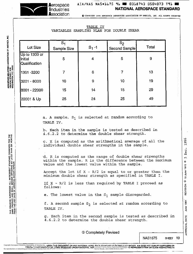
Lot Size Up to 1300 or Initial Qualification
1301 -3200
3201 - 8000 8001 -22000
22001 &Up
TABLE IV VARIABLES SAMPLING PLAN FOR DOUBLE SHEAR
SI Sample Size
5
7
10
15
25
SI -1
4
6
9
14
24
s2 Second Sample
5
7
10
15
25
Total
9
13
19
29
49
a. A sample, SI is selected at random according to TABLE IV.
b. Each item in the sample is tested as described in 4.6.2.2 to determine the double shear strength.
c. X is computed as the arithmetical average of all the individual double shear strengths in the sample.
-d. R is computed as the range of double shear strengths within the sample. R is the difference between the maximum value and the lowest value within the sample.
Accept the lot if X - R/2 is equal to or greater than the minimum double shear strength as specified in TABLE I.
If X - R / 2 is less than required by TABLE I proceed as follows:
e. The lowest value in the Cl sample disregarded.
f. A second sample S2 is selected at random according to TABLE IV.
g. Each item in the second sample is tested as described in 4.6.2.2 to determine the double shear strength.
O Completely Revised
9 n n -I
N t- o> r
u> r
3
USE OF OR RELIANCE UPON THIS DOCUMENT OR ANY NATIONAL AEROSPACE STANDARD IS ENTIRELY VOLUNTARY. AIA DOES NOT OUALIFY SUPPUERS OR CERTIFY CONFORMANCE OF ITEMS PRODUCED>NDER NtTLONAL AEROSPACE STANDARDS. AIA MAKES NO REPRESENTATION OR CLAIM RESPECTING il\ - .r ̂ ...__^.. .-. --.--..- ....,-. e-.-.
Copyright Aerospace Industries Association of America Inc. Provided by IHS under license with AIA/NAS Licensee=Fuerza Aerea Argentina/5969982001
Not for Resale, 10/17/2008 09:55:51 MDTNo reproduction or networking permitted without license from IHS
--``,,,`,,`,``,,`````,,```,`,,-`-`,,`,,`,`,,`---
A I A / N A S N A S x L b ï 5 96 = 0338743 0504074 928 .,2rospace Industries NATIONAL AEROSPACE STANDARD I Association 0 COPYRIGHT 1996 AEROSPACE INDUSTRIES ASSOCIATION OP AMERICA. INC. ALL RIGHTS RËSERVED
h. X and R are computed for the total S2 sample (the remainders of the SI samples plus the S2 second sample).
Accept the lot if X - R/2 is equal to or greater than the minimum double shear strength as specified in TABLE I. Reject the lot if X - R/2 is less than required by TABLE I.
4.6.2.2 Procedure - Prior to testing, each fastener shall be disassembled to remove the sleeve. The screw is then inserted into the nut until the screw breaking groove is protruding through the head of the nut. Shear tests are then performed in a fixture substantially conforming to Figure 3. Other types of shearing fixtures may be used if acceptable to buyer. Loading rate shall be as specified in Figure 3 . This test is not applicable to assembly lots of fasteners having a grip less than twice the nominal diameter for protruding head fasteners or less than 2-1/2 times nominal diameter for flush head fasteners. Acceptance in these cases will be based on hardness tests.
4.6.2.3 Data Rewired - The manufacturer’s test report on each assembly lot of fasteners shall provide the actual double shear strength as determined by test on each item of the sample and shall include the variables sampling plan calculation of Paragraph 4.6.2.1. The certified report of initial qualifications tests shall additionally include:
a. Rockwell hardness of each alloy steel screw and nut in the test sample. Readings shall be taken on the base material after removal of cadmium plate.
b. A description of failures supported by photographs of a typical failure.
.. .
c. A description and photograph of the test Set-up
4.6.3 Sinale Shear LaD-joint (Initial Oualification Onlv) . 4.6.3.1 Procedure - Five of the joint specimens shown in Figure 4 and TABLE V shall be assembled,each joint using two flush blind fasteners of appropriate grip length. All sheet material of one thickness shall be taken from the same parent stock.The center line of the fastener shall be located within .O10 inches of the specimen center line.
O Completely Revised
I
USE OF OR RELIANCE UPON THIS MXXIMENT OR ANY NATIONAL AEROSPACE STANDARD IS ENTIRELY VOLUNTARY. AIA WES NOT QUALIM SUPPUERSOR CERTi,~-C_9NoRM4N_CE”o~-~~Ms, ~~~~tJJEDlJN~~ij !+TLONAL AEROSPACE STANDARDS. AIA MAKES NO REPRESENTATION OR C I A M RESPEeTING t i l
3 n n 4
; 3J 2 n 3
- m a
n
3
2 2
c 7
r
z
> ILI U
e W m
al c 3 7
F
w c O -I 4 > O a n n
a
Copyright Aerospace Industries Association of America Inc. Provided by IHS under license with AIA/NAS Licensee=Fuerza Aerea Argentina/5969982001
Not for Resale, 10/17/2008 09:55:51 MDTNo reproduction or networking permitted without license from IHS
--``,,,`,,`,``,,`````,,```,`,,-`-`,,`,,`,`,,`---

~~~
A I A / N A S NASxlb75 î b 0338743 0504075 8b4 Aerospace Industries NATIONAL AEROSPACE STANDARD Association 6iCOPYRIGHT 1996 ABROSPACB INDUSTRIBS ASSOCIATION OF AMBRICA. INC. ALL RIGHTS RESBRVIID
The spacers shown in Figure 4 shall be attached to the primary specimen by bonding or riveting to form a sound structural joint. An extensometer shall be attached effectively along the center line of the specimen at a constant total gage length of four inches. Each of the three loads defined in TABLE V shall be applied to the specimen with load relaxations to about 100 pounds after each loading. The specimen is then loaded to ultimate failure. It is permissible to disconnect the extensometer system after the three load relocations and before loading to ultimate failure to prevent damage to the instrumentations.
A-i
rh TOOL STEEL BUSH 1 NG
NO CSK FOR FLUSH FASTENERS APPLY SHEAR L O A D TO STRAIGHT SHANK ONLY.
I SECTION B-8
FIGURE 3 DCNBLE SHEAR TEST
O Completely Revised
I USE OF OR RELIANCE UPON THIS WCUMENT OR ANY NATIONAL AEROSPACE STANDARD IS ENTIRELY VOLUNTARY AIA DOES NOT OUALIM SUPPUERS OR C E ~ ~ ~ _ c O N O ~ ~ A ~ ~ E - O ~ ~ ~ E M S PROOUCED UNDER NATIONAL AEROSPACE STANDARDS. AIA MAKES NO REPRFSFNTATICIN CIR Cl A l u DCeDcC?IIitC ,*I
Copyright Aerospace Industries Association of America Inc. Provided by IHS under license with AIA/NAS Licensee=Fuerza Aerea Argentina/5969982001
Not for Resale, 10/17/2008 09:55:51 MDTNo reproduction or networking permitted without license from IHS
--``,,,`,,`,``,,`````,,```,`,,-`-`,,`,,`,`,,`---

A I A / N A S NASnLb75 ï b m 03313743 050407b 7 T O m Aerospace I ndust r ies NATIONAL AEROSPACE STANDARD m a Association OCOPYRIGHT 1996 AEROSPACE INDUSTRIES ASSOCIATION OF MBRICA, INC. ALL RIGHTS RESBRVBD
4.6.3.2 shear lap joint specimens, as shown in Figure 4, shall exhibit total load carrying strengths equal to or greater than twice the ultimate strength per fastener and twice the yield strength per fastener value shown in TABLE V for each of the various size fasteners and specimens.
AcceDtance Criteria - Each of the single
4.6.3.3 Data Rewired
a. Ftu, Fty and percent elongation of two tensile coupons of the parent stock.
b. dimensions of the lap specimen including hole size.
Suitable recording of the physical
c. Autographic load-extension records of each of the specimens tested as described above.
d. failure.
Value of failing load and description of
e. Notation of any unusual characteristics of specimens during test such as head tilt, sleeve failure, etc., with photographs if necessary.
f. the alloy steel fastener components (except sleeve). Readings shall be taken on the base material after removal of cadmium plate.
g . each specimen after test. Failed specimens shall accompany test reports.
h.
Record Rockwell hardness readings of each of
Suitable identification of the remnants of
..
Description and photographs of test Set-up.
O Completely Revised NAS1675 SHEET 22
I USE OF OR RELIANCE UPON THIS DOCUMENT OR ANY NATIONAL AEROSPACE STANDARD IS ENTIRELY VOLUNTARY. AIA W E S NOT QUALIFY SUPPUERS OR CERTIFY CONFORMANCE OF ITEMS PRODUCED UNDER NATIONAL AEROSPACE STANDARDS. AIA MAKES NO REPRFSFNTATION OR Ci A I M UFSLFllflNn II,
Copyright Aerospace Industries Association of America Inc. Provided by IHS under license with AIA/NAS Licensee=Fuerza Aerea Argentina/5969982001
Not for Resale, 10/17/2008 09:55:51 MDTNo reproduction or networking permitted without license from IHS
--``,,,`,,`,``,,`````,,```,`,,-`-`,,`,,`,`,,`---

~ _ _
A I A / N A S NAS*Lb75 96 0338743 050Lt077 b37 Aerospace I ndust r ¡es NATIONAL AEROSPACE STANDARD Association Q I ~ P ~ I G S I T 1996 AEROSPACE INDUSTRIES ASSOCIATION OF AMBRICPi, INC. ALL RIGHTS RESERVED
EXTENSOMETER PICK-UP POINT W=8D
I I
APPLIED 9- LOAD APPLIED 1 LOAD I
I I I 9 I
t l y--- 1 3 ~
I 1 I, I ! :
l
~ APPLIED o I I ' : i , I i LOAD
A
SPACER - t 2
TEST FASTENERS
.. .
FIGURE 4 LAP SHEAR SPECIMEN
O Completely Revised NAS1675 SHEET 23
Copyright Aerospace Industries Association of America Inc. Provided by IHS under license with AIA/NAS Licensee=Fuerza Aerea Argentina/5969982001
Not for Resale, 10/17/2008 09:55:51 MDTNo reproduction or networking permitted without license from IHS
--``,,,`,,`,``,,`````,,```,`,,-`-`,,`,,`,`,,`---

rospa pace I ndust r ¡es
A I A / N A S NASuLb75 9b = 0338793 0504078 573
NATIONAL AEROSPACE STANDARD I Association 0 COPYRIGHT 1996 ABROSPACE INDUSTRIES ASSOCIATION OF AMERICA, INC. ALL RIGHTS SER^
Fastener Class
1 2 3 4
Fastener Size
Hole Sheet Alloy t l t2 Diameter Loading Sequence Required Strength
D (Lb Per Fig 3) Lb Per Fastener +.O03 -.mo First Second Third Yield Ultimate
Clad 7075-T6 900 1200 1500 625 950
Clad7075T6 .071 071 6AI-4V Ti 900 1200 1500 625 1350
Clad 7075T6 900 1200 1500 625 950 750 1000 1250 470 725 . 1 650
1 2 3 4
3
Clad 7075-T6 .O80 1100 1500 1900 750 1275 6AI-4V Ti .O71 1100 1500 1900 750 2000
1000 1300 1600 650 860 1100 1500 1900 750 1275
Clad 7075-T6 .07, Clad 7075-T6 .O80
.1990
NOTE : a. Yield strength is defined as that load which produces a permanent set across the joint of .O12 inch for the 08, 3 and 4 fastener sizes and 4% of nominal fastener diameter for the larger sizes.
b. Clad 7075-T6 aluminum is in conformance with QQ-A-250/13. 6A1-4V titanium is in conformance with AMs4911
I USE OF OR RELIANCE UPON THIS DOCUMENT OR ANY NATIONAL AEROSPACE STANDARD IS ENTIRELY VOLUNTARY. AIA DOES NOT WAUFY SUPPUERS OR C E R T ' . ~ - o " . F , q R _ M q N - O ~ ~ ~ ~ ~ ~ ~~gQUCEDiJN~&~ NtT!ON& AEROSPACE.STANDARDS. AIA MAKES NO REPRESENTATION OR CLAIM RESPECTING (11
O Completely Revised
Copyright Aerospace Industries Association of America Inc. Provided by IHS under license with AIA/NAS Licensee=Fuerza Aerea Argentina/5969982001
Not for Resale, 10/17/2008 09:55:51 MDTNo reproduction or networking permitted without license from IHS
--``,,,`,,`,``,,`````,,```,`,,-`-`,,`,,`,`,,`---

Aerospace A I A / N A S NAS*1675 96 m 0338743 050407q m I ndust r ¡es NATIONAL AEROSPACE STANDARD
0 COPYRIGHT 1996 AEROSPACE INDUSTRIES ASSOCIATION OP AMERICA. INC. ALL RIGHTS R E S E R ~ ~ D Association
1300 or less or Initial Qualification 1301 - 3200 3201 -8000
8001 -22000 22001 and Up
4.6.4 Tensile Strensth
Class1,2,3&4 5
7 10 15 25
4.6.4.1 for tensile strength tests shall be in accordance with TABLE VI. Accept the lot if all samples equal or exceed the minimum tensile strength as specified in TABLE I. Reject the lot if any one of the samples has less than minimum tensile strength specified in TABLE I
SamDlincr and AcceDtance Criteria - Sampling
TABLE VI SAMPLING FOR TENSION TEST AND CLAMP-UP PRELOAD TEST.
Lot Size
4.6.4.2 Procedure - Tension strength tests shall be performed in a fixture conforming to Figure 5. All Class 1 and Class 2 fasteners shall be installed in minimum grip + . 0 0 5 / - - 0 0 0 . All Class 3 fasteners shall be installed in maximum grip +.OOO/-.005. Fasteners having a grip length less than twice the nominal diameter need not be tested; acceptance will be based on hardness t e s t per 4.6.9. All Class 3 millable fastener heads shall be milled prior to testing. Class 4 fasteners shall be installed in minimum grip +.005/-.O00 and maximum grip +.OOO/--005. Loading rate shall be as specified in Figure 5 .
4.6.4.3 Data Reauired - The manufacturer's test report on each assembly lot of fasteners shall include the actual tension strength.' as determined by test on each item of the sample. The certified report of initial qualification test shall additionally include :
I NAS1675 SHEET 25
O
-I
u PI =I
n a n
n n
N . r
m c -3 y1
a
I-
3
2 z
5 W U
d W ch
m c 3 -3
7
w I- U
2 U >
a
a
8 a a
Copyright Aerospace Industries Association of America Inc. Provided by IHS under license with AIA/NAS Licensee=Fuerza Aerea Argentina/5969982001
Not for Resale, 10/17/2008 09:55:51 MDTNo reproduction or networking permitted without license from IHS
--``,,,`,,`,``,,`````,,```,`,,-`-`,,`,,`,`,,`---

Aerospace Industries NATIONAL AEROSPACE STANDARD
A I A / N A S NAS*i<Lb75 ï b m 0338743 0504080 323 m
Association Q copYRIGI(T 1996 AEROSPACE INDUSTRIES ASSOCIATION OP AMERICA, INC. ALL RIGHTS RESERVED
a. Rockwell hardness readings of each alloy steel fastener component. Readings shall be taken on the base material after removal of cadmium plate.
b. Load strain curve to failure for each specimen.
c. A description of failures supported by photographs of a typical failure.
d. A description and photographs of the test Set-up.
CUP MUST BE COUNTERSUNK FLUSH HEAD FASTENERS
80LT HOLE CENTER LINE MUST BE PERPENDICULAR TO
THESE SURFACES WITHIN 0 ' 1 5'
TO FIT
\RELIEVE CORNER TO CLEAR HEAD TO SHANK FILLET FOR PROTRUDING OR FLUSH HEAD FASTENERS. SEE TABLE FOR LIMITS.
I
FIGURE 5 Tension Test
NAS1675 SHEET 26
USE OF OR RELIANCE UPON THIS DOCUMENT OR ANY NATIONAL AEROSPRCE STANDARD IS ENTIRELY VOLUNTARY. AIA WES NOT OUALIW SUPPUERC OR CERTIM CONFORMANCE OF ITEMS PRODUCED UNDER NATLONKAEROSPACE-STANDARDS. AIA MAKES NO REPRESENTATION OR CLAIM RESPECTING f i ) -. ,r C. ..-. "., I N nr ,_C. .C ?O" ..I" n. ..V.̂ < I. . - . --. .- .-
Copyright Aerospace Industries Association of America Inc. Provided by IHS under license with AIA/NAS Licensee=Fuerza Aerea Argentina/5969982001
Not for Resale, 10/17/2008 09:55:51 MDTNo reproduction or networking permitted without license from IHS
--``,,,`,,`,``,,`````,,```,`,,-`-`,,`,,`,`,,`---

Aerospace A I A I N A S NAS*3bï5 96 0338743 0504083 Ob8 Industries NATIONAL AEROSPACE STANDARD Association 0 COPYRIGHT 1996 AEROSPACE INDUSTRIES ASSOCIATION OP AMERICA, INC. ALL RIGHTS RESBRVBD
4.6.5 ClamD-UD PreLoad - Initial qualification for classes 1,2,3; qualification and lot acceptance for class 4.
14.6.5.1 test shall be in accordance with TABLE VI. Clamp-up preload may be run in conjunction with tension strength test (paragraph 4.6.4).
SamDlins - Sampling for clap-up preload
4.6.5.2 1312 Test 16,using either the load cell, paddle, or split shim method. If the paddle or split shim(s) method is used,clamp-up pre-load tests shall be performed in conjunction with 4.6.4 with a split steel paddle or steel shim(s) to obtain the appropriate grip condition per 4.6.4.2. The area between the tension cups shall be lubricated to facilitate removal of the shim(s) or rotation of the paddle. Each half of the split shim or paddle shall be loaded with a spring or a dead weight of five pounds I one pound. The tension load of the 4.6.4 test is applied to the tension cups until the split shim(s) are removed or the paddle rotates. The load on the tension cups at this time is the tension pre-load of the test fastener.
Procedure - Testing shall be per MIL-STD-
4.6.5.3 pre-load(for all classes) must equal or exceed 20% of the fastener tensile strength as given in TABLE I. See 3.8.4 for additional requirements for class 4
4.6.5.4 determined by tests on each item of the sample.
AcceDtance Criteria - The clamp-up
Data Rewired - Actual tension pre-load as
4.6.6 Sheet Take-UD (Initial Qualification Only)
4.6.6.1 Procedure - Each fastener of the sample is driven in a device essentially as presented in Figure 6. Hole size for that fastener shall be in conformance with TABLE V. Countersink shall provide head flushness within f.OO5.The nuts supporting the lower sheet shall be adjusted to provide a gap between sheets of .O32 I.002 before driving.
4.6.6.2 sample shall engage the lower sheet of the test device and shall clap it against the upper plate.
4.6.6.3 Data Required - A description of any installation discrepancies and photographs of the tested fastener driven in the Figure 6 device.
AccePtance Criteria - Each fastener of the
I NAS1675 SHEET 27 I
USE OF OR RELIANCE UPON THIS DOWMENT OR ANY NATIONAL AEROSPACE STANDARD IS ENTIRELY VOLUNTARY. AIA W E S NOT QUALIFY SUPPLIERS OR CER~,~-C_q”?R-MqN_CE-O~~~EMS. ?@ücHl UNDER NATIONAL AEROSPACE STANDARDS. AIA MAKES NO REPRESENTATION OR CLAIM RESPECTING (1)
Copyright Aerospace Industries Association of America Inc. Provided by IHS under license with AIA/NAS Licensee=Fuerza Aerea Argentina/5969982001
Not for Resale, 10/17/2008 09:55:51 MDTNo reproduction or networking permitted without license from IHS
--``,,,`,,`,``,,`````,,```,`,,-`-`,,`,,`,`,,`---

Aerospace I ndust r i es
A I A / N A S NASxLb75 96 D 0338743 0504082 T T 4 NATIONAL AEROSPACE STANDARD
@COPYRIGHT 1996 AEROCPACB INDUSTRIES ASSOCIATION OF AMERICA, INC. ALL RIGHTS RESBRYBD Association
.. . L n A x GRIP + .O32
FIGURE 6 SHEET TAKE-UP TEST
4.6.7 Vibration Endurance (Initial Qualification only)
4.6.7.1 Procedure - Fãsteners shall be installed in 2024-T4 aluminum test plates as shown in Figure 10. A total of 16 specimens of given grip length -is required in each diameter of 08, 3 and 4 fastener size. Eight specimens will be installed in the -_-- minimum grip range of .532 (+.002/-.OOO) ~~ and eight specimens will be install-ed in the maximum grip range of .594 (+.OOO/-.002).
A total of 12 specimens of given grip length is required in each diameter of 5 and 6 fastener size. Six specimens will be installed in minimum grip range of .532 (+.002/--000) and six specimens will be installed in the maximum grip range of .594 (+.OOO/--002).
I NAS1675 SHEET 28
Copyright Aerospace Industries Association of America Inc. Provided by IHS under license with AIA/NAS Licensee=Fuerza Aerea Argentina/5969982001
Not for Resale, 10/17/2008 09:55:51 MDTNo reproduction or networking permitted without license from IHS
--``,,,`,,`,``,,`````,,```,`,,-`-`,,`,,`,`,,`---

Aerospace AIA/NAS N A S E 2 6 7 5 96 m 0 3 2 8 7 4 3 0504083 930 m Industries NATIONAL AEROSPACE STANDARD Association 0 COPYRIGHT 1996 AEROSPACE INDUSTRIES ASSOCIATION OF AMERICA, INC. ALL RIGHTS RBSERVGD
Reference lines shall be scribed on the nut to test plate and the corebolt to nut, so that any relative motion or loosening can be determined. Mount test plate in test fixture as shown in Figure 9. Adjust "Jiffy" 500 riveting gun position for static clearance of 3/32 inch between specimen plate and hammer. Use 1 1/4 diameter flat rivet set (hammer). Maintain constant 72 p.s.i air pressure during test. Vibration testing shall be interrupted at intervals of 30 seconds, one minute, one minute 30 seconds, two minutes, two minutes 30 seconds, three minutes, five minutes, seven minutes, ten minutes, fifteen minutes, and twenty minutes fo r examination of fasteners. Fasteners shall be examined for initial assembly, initial corebolt rotation, free rotation, axial movement and failure.
4.6.7.2 Definitions.
a. initial assembly rotation - fastener assembly rotation beyond 10" in the test plate.
b. Initial corebolt rotation - rotation of corebolt to nut beyond 10".
c. Free rotation - when fastener assembly turns 360' in plate with finger pressure.
d. Axial movement - free axial movement of the fastener assembly in plate.
4.6.7.3 rotation of the screw relative to nut or complete loss of prevailing locking torque or fracture of any component within 20 minutes test duration constitutes failure.
AcceDtance Criteria - 360' or greater
4.6.7.4 Data Rewired.
a. The relative rotation between any component shall be recorded with mode and endurance time.
b. Photographs of test Set-up showing any failures. Recorded report statkg failure mode and endurance t ime .
I 1 NAS1675 SHEET 29
USE OF OR RELIANCE UPON THIS DOCUMENT OR ANY NATIONAL AEROSPACE STANDARD IS ENTIRELY VOLUNTARY. AIA DOES NOT QUALIM SUPPUERS OR CERTIFY CONFORMANCE OF ITEMS PRODUCED UNDER NATIONAL AEROSPACE STANDARDS. AIA MAKES NO REPRESENTATION OR CLAIM RESPECTING 111
Copyright Aerospace Industries Association of America Inc. Provided by IHS under license with AIA/NAS Licensee=Fuerza Aerea Argentina/5969982001
Not for Resale, 10/17/2008 09:55:51 MDTNo reproduction or networking permitted without license from IHS
--``,,,`,,`,``,,`````,,```,`,,-`-`,,`,,`,`,,`---

~
Aerospace A I A / N A S N A S a L b 7 5 96 0318743 0504084 877 I ndust r i es NATIONAL AEROSPACE STANDARD Association OICOPYRIGHT 1996 AEROSPACE INDUSTRIES ASSOCIATION OF AMERICA, INC. ALL RIGlfTC RESERVED
4.6 .8 Tension-Tension Faticrue (Initiai ûualification Onlv)
4.6.8.1 Procedure - Five specimens of each material class, head style and diameter being submitted for qualification shall be tested in tension-tension fatigue. The test apparatus shall conform to that shown in Figure 5. All fasteners shall be installed in a mean grip condition with a removable shim or washer that may be removed after driving to remove all pre-load from the fastener. Fatigue testing machines, specimen holding fixtures, and test Set-up shall be per NAS1069. Test loading shall cycle between a maximum load equal to 60% of the tensile strength as defined in Table I and a minimum load equal to 6% of the tension strength (R = .1) this includes -08 diameter, Class 4. Class 4, -3, -4, -5, -6 diameters shall be tested at a maximum load equal to 50% of the tensile strength as defined in Table I and a minimum load equal to 5% of the tension strength ( R = .1 1 .
The cycling speed shall not exceed 6000 cycles per minute and tests shall be performed at room temperature. Testing need not be continued past 100,000 cycle on any one fastener.
4 .6 .8 .2 AcceDtance Criteria - Each item in the sample shall have a fatigue life equal to or exceeding 15,000 cycles. The average fatigue life of all items in the sample shall equal or exceed 30,000 cycles.
4.6.8.3 Data Rewired.
a. Rockwell hardness of all alloy steel fastener components. Readings shall be taken on the base material after removal of cadmium plate.
b. Fatigue life in cycles for each item of the sample with a description of the failure.
c. Photographs of test Set-up and typical failure.
I USE OF OR RELIANCE UPON THIS DOCUMENT OR ANY NATIONAL AEROSPACE STANDARD IS ENTIRELY VOLUNTARY. AIA W E S NOT QUALIFY SUPPLIERS OR CERTIM CONFORMANCE OF ITEMS PRODUCED UNDER NATIONAL AEROSPACE STANDARDS. AIA MAKES NO REPRESENTATION OR CLAIM RFSPFCïINI, f ï i
Copyright Aerospace Industries Association of America Inc. Provided by IHS under license with AIA/NAS Licensee=Fuerza Aerea Argentina/5969982001
Not for Resale, 10/17/2008 09:55:51 MDTNo reproduction or networking permitted without license from IHS
--``,,,`,,`,``,,`````,,```,`,,-`-`,,`,,`,`,,`---

~~
Aerospace A I A / N A S NAS*lb75 96 0338743 0504085 703
I ndustr ¡es NATIONAL AEROSPACE STANDARD Association 0 COPYRIGHT 1996 AEROSPACE INDUSTRIES ASSOCIATION OF AMBRICA. INC. ALL RIGHTS RESERVED
I
4.6.9 Hardness - Hardness testing is applicable to both the screw and nut of Class 1 and Class 2 blind fasteners and to the screw only of Class 3 blind fasteners.
4.6.9.1 SamDlinq - Five fastener assemblies shall be selected at random for hardness testing regardless of the lot size.
4.6.9.2 Procedure.
4.6.9.2.1 Allov Steel ComDonents (Class 1 Screws and Nut, Class 3 Screws) - The hardness test shall be by Rockwell C scale or Rockwell 45N scale at three places on suitably prepared surfaces of unmounted components or by Rockwell 30N or 45N at three places on specimens firmly mounted and polished as for metallographic examination. Microhardness values shall not be used to determine the hardness level of components. Rockwell 15N may be used only when components are too small to permit use of the Rockwell 30N impressions. Hardness scales other than those referenced above may be used with the conversions of A S D I E 140 being applicable. In cases of controversy, only the 30N scale shall be used on specimens firmly mounted and polished.
4.6.9.2.2 Corrosion and Heat Resistant Steel Comnonents (Class 2 Screws and Nuts) - Rockwell (HRc) reading shall be taken on a convenient clean flat surface of each fastener component. Superficial N scale readings may be taken in lieu of the HRc readings on small components. Conversion of superficial hardness readings to HRc readings shall be in accordance with ASTM E140
4.6.9.3 Accentance Criteria.
4.6.9.3.1 Allov Steel Components (Class 1 Screws and Nuts, Class 3 Screws) - Accept the lot if the average of the readings taken on each component is within KRc 39-43, R30N 58.5-62 or R45N 42-46.5.
NAS1675 SHEET 31
USE OF OR RELIANCE UPON THIS COCUMENT OR ANY NATIONAL AEROSPACE STANDARD IS ENTIRELY VOLUNTARY. AIA D O S NOT QUALIM SUPPUERC OR CERTIN CONFORMANCE OF ITEMS PRODUCED UNDER NATIONAL AEROSPACF STANi7ARD.i A I A MAKFS Nn RFPQFSFNTATION OR CI A I M C)ECDCPTINC: t i 1
Copyright Aerospace Industries Association of America Inc. Provided by IHS under license with AIA/NAS Licensee=Fuerza Aerea Argentina/5969982001
Not for Resale, 10/17/2008 09:55:51 MDTNo reproduction or networking permitted without license from IHS
--``,,,`,,`,``,,`````,,```,`,,-`-`,,`,,`,`,,`---

A I A I N A S NASwLb75 96 03L8743 050408b b4T Aerospace Indust r ¡es NATIONAL AEROSPACE STANDARD Association OICOPYRIGHT 1996 AEROSPACB INDUSTRIES ASSOCIATION OP AMERICA, INC. ALL RIGHTS RBSFRVBD
4.6.9.3.2 ComDonents (Class 2 Screws and Nuts) - Hardness for all components in the sample shall be in the range HRc 30-45.
Corrosion and Heat Resistant Steel
4.6.9.4 readings identified where applicable to the hardness test location.
Data Remired - A record of all hardness
4.6.10 Screws and Nuts, Class 3 Screws).
Surface Effects - Alloy Steel components(C1ass 1
4.6.10.1 be selected at random for metallographic examination regardless of the lot size.
SamDlina - Five fastener assemblies shall
4.6.10.2 undesirable surface condition shall be determined by microexamination. Specimens shall be taken from a transverse section of the head and threaded shank of the finished nut and screw. The etchant shall be 5% nital. Microscopic examination shall be made at a magnification of 100 diameters. In addition to the microexamination, a microhardness test using a Knoop indicator with a 500 gram load shall also be made on the same mounted specimens. Impressions shall be made at six locations on the screw and six locations on the nut per figure 7. if one or more of the six reading on a part is suspected of being inaccurate, the suspected reading shall be replaced by the average of three additional readings taken from a similar location; however, the average of any one set of three- additional readings cari be used to replace only one suspect reading.
Procedure - The absence or presence of an
Copyright Aerospace Industries Association of America Inc. Provided by IHS under license with AIA/NAS Licensee=Fuerza Aerea Argentina/5969982001
Not for Resale, 10/17/2008 09:55:51 MDTNo reproduction or networking permitted without license from IHS
--``,,,`,,`,``,,`````,,```,`,,-`-`,,`,,`,`,,`---

Aerospace A I A / N A S NAS*Lb75 96 0338743 0504087 586 H
Industries NATIONAL AEROSPACE STANDARD Assai at¡ on 0 COPYRIGHT 1996 ABROSPACB INDUSTRIES ASSOCIATION OP AMERICA, INC. ALL RIGHTS RESER-
O 0 0
OF SCREW
7 $-OF WALL TH 1 CKNESS
+ +.--o--- O 0 0
A
---
i (COF NUT .O035 INCH MAX
FIGURE 7 LOCATION OF MICROHARDNESS IMPRESSIONS
4.6.10.3 each of the following conditions are met:
Acceptance Criteria - Accept the lot if
a. There shall be no visual evidence of carbon enrichment, nitrogenization or other case hardening and there shall be no complete decarburization. Partial decarburization shall not extend more than .O03 inch from the surface.
b. For the microhardness test, the average of the three readings at the thread roots shall be within 30 Knoop numbers of the average of the three readings at the centerline.
4.6.11 Discontinuities.
4.6.11.1 Samplinas - Sampling for discontinuities shall be at random in accordance with MIL-STD-105, Table II-A, Inspections Level S-3 per Table I, AQL 1.5.
4.6.11.2 Procedures - The presence of discontinuities such as cracks, laps, seams and inclusions for components made of non-magnetic material shall be fluorescent penetrant inspected per MIL-STD-6866. The presence of discontinuities such as cracks, laps, seams and inclusions for components made of magnetic material shall be inspected per ASTM E 1444.
Representative specimens showing indications shall be further examined microscopically to determine whether the discontinuities are in accordance with limits specified herein.
i NAS1675 SHEET 33
USE OF OR RELIANCE UPON THIS DOCUMENT OR ANY NATIONAL AEROSPACE STANDARD IS ENTIRELY VOLUNTARY. AIA DOES NOT QUALIM SUPPLIERS OR CERTIFY CONFORMANCE OF ITEMS PRODUCED UNDFR N A T l n N A l A C C l n C D A P C C T 6 N n A D n C A I L L ~ A V C C i s - ~ c o ~ c e c . i - * - i n i i -- -* .<.. -----I.-.- ..
Copyright Aerospace Industries Association of America Inc. Provided by IHS under license with AIA/NAS Licensee=Fuerza Aerea Argentina/5969982001
Not for Resale, 10/17/2008 09:55:51 MDTNo reproduction or networking permitted without license from IHS
--``,,,`,,`,``,,`````,,```,`,,-`-`,,`,,`,`,,`---
A I A / N A S NASS1675 96 = 0318743 0504088 412 NATIONAL AEROSPACE STANDARD
COPYRIGHT 1996 AEROSPACE INDUSTRIES ASSOCIATION OF AMBRICR, INC. ALL RIGmS RBSBRYED
4.6.11.3 Acceptance Criteria - The finished components shall be within the limits specified in 3.9.2.
4.6.12 Installation.
4.6.12.1 Samplincr and Acceptance Criteria Sampling and acceptance criteria for installation tests shall be in accordance with Table VII. The samples for initial qualification shall consist of 100 (Class 4, 2 0 ) fasteners of approximately one diameter grip length and 100 (Class 4, 20) fasteners of approximately two diameters grip length and 100 (Class 4, 20) fasteners with a grip length between three and four times the nominal fastener diameter. Table VI1 indicates the and the acceptance criteria for each group of qualification samples. Major defects are split sleeves, screw failures, loose fasteners (as determined by torque test), nut head failures and stem break-off outside of limits. Minor defects are buckled sleeves and flared sleeves. Break-off limits and torque values shall be as specified in Table IX (see Figure 11 for a pictorial definition of buckled, flared and split sleeves, screw failures and nut head failures) .
installation grip condition
4.6.12.2 Procedures - Fasteners shall be driven in hardened steel plates having a minimum hardness of Rc 46 and a surface finish on the blind head side of RHR 63 maximum per ANSI/ASME B46.1. Hole sizes shall be in conformance with Table V. Countersinks in the drive plates shall receive flush head fasteners with a flushness tolerance of k.003. Driven fasteners shall be examined visually for installation. discrepancies as shown in Figure 11. Screw break-off levels shall be measured with a suitable gage. The torque values of Table IX shall be applied to the installed fasteners with the appropriate driving tool nose piece and any resulting rotation will be noted.
NAS1675 SHEET 34 Copyright Aerospace Industries Association of America Inc. Provided by IHS under license with AIA/NAS Licensee=Fuerza Aerea Argentina/5969982001
Not for Resale, 10/17/2008 09:55:51 MDTNo reproduction or networking permitted without license from IHS
--``,,,`,,`,``,,`````,,```,`,,-`-`,,`,,`,`,,`---

Aerospace A I A / N A S N A S x L b 7 5 96 W 0338743 0504089 359 W
Industries NATIONAL AEROSPACE STANDARD Associati on OCOPYRIGHT 1996 AEROSPACE INDUSTRIES ASSOCIATION OF AMERICA, INC. ALL RIGmS RESERVED
TABLE VI1 INSTALLATION TESTS
Lot Size
Up to 1300
1301 - 3200
3201 -8000
8001 - 22000
22001 and Up Qualification
Group Class 1,2,3
Class 4
Sample Size
- Total
8
10
14
24
34
-
1 O 0
20
dax. Grip f .o01
4
5
7
12
17
50
10
Min. Grip f .o01
4
5
7
12
17
50
10
Major Defects
Accept
O
O
O
O
1
-
2
O
Reject
3
1
Major & Minor Defects
Accept
5
O
- Reject
1
2
2
3
4
-
6
1
4.6.12.3 Data Rewired - The certified report of initial qualification test shall include as a minimum:
a. Record of all screw break-off positions.
b. A record of all misformed or split sleeves with detailed photographs of typical failures.
c. The number of fasteners that turn in the fastener looseness torque test.
d. A record of the screw or nut failures with detailed photographs of typical failures.
e. Photographs of the completed panels with installed fasteners viewed from the sleeve side.
NAS1675 SHEET 35 I
USE OF OR RELIANCE UPON THIS DOCUMENT OR ANY NATIONAL AEROSPACE STANDARD IS ENTIRELY VOLUNTARY. AIA DOES NOT QUAUM SUPPUERS OR CERTIFY CONFORMANCE OF ITEMS PRODUCED IINOFR N A T l n N A l A C R R C D A P ' E C T b w n a o n c A I A unucc un n æ m n c = æ h m I T I n w no CI .I., ~CCO~- . . IC n - ~
Copyright Aerospace Industries Association of America Inc. Provided by IHS under license with AIA/NAS Licensee=Fuerza Aerea Argentina/5969982001
Not for Resale, 10/17/2008 09:55:51 MDTNo reproduction or networking permitted without license from IHS
--``,,,`,,`,``,,`````,,```,`,,-`-`,,`,,`,`,,`---

A I A / N A S N A S S 1 6 7 5 96 0338743 0504090 070 - - xospace I Industries NATIONAL AEROSPACE STANDARD
Lot Size
Under 10,000
or Initial Qualification Over 10,000
0 COPYRIGHT 1996 AEROSPACE INDUSTRIES ASSOCIATION OF AMERICA, INC. ALL RIGHTS RESERVED
Minim um P revai I in g Sample Fastener Torque Inch Lbs.
Size Size Class Class Class Class 1 2 3 4
08 1 1 a4 1 3 1-1/2 1-1/2 1 1-1/2
5 4 2-112 2-1/2 1-1/2 2-1/2
10 6 4 4 4 5 3-1/2 3-1/2 3-1 /2
4.6.13 Lockinq Feature - Prevailincr Toraue.
4.6.13.1 Sarwlins and AcceDtance Criteria Sampling and acceptance criteria for prevailing torque shall be in accordance with Table VI11 when tested in conformance with Paragraph 4.6.13.3. Accept the lot, if all samples equal or exceed the minimum prevailing torque as specified in Table VIII. Reject the lot if any one of the samples has less than the minimum prevailing torque specified in Table VIII.
TABLE VI11 SAMPLING FOR PREVAILING TORQUE
4.6.13.2 Prevailing torque, as referred to herein, is the minimum torque recorded, on the torque indicating device, through a minimum disassembly rotation of 720' between the nut and screw components for -3 grip and greater. 360' for -1 and -2 grip parts and aluminum parts.
4.6.13.3 Prevailing torque on each fastener may be determined by either Method I or Method II as outlined below. However, only Method I may be used for qualification purposes.
METHOD I. - SPLIT BLOCK PROCEDURE.
a. Each fastener to be tested shall be installed into a split block which is equivalent in thickness to the maximum grip +.OOO/-.O02 for the fastener to be tested. Single or multiple hole split blocks are optional.
(driven)
1 NAS1675 SHEET 36 Copyright Aerospace Industries Association of America Inc. Provided by IHS under license with AIA/NAS Licensee=Fuerza Aerea Argentina/5969982001
Not for Resale, 10/17/2008 09:55:51 MDTNo reproduction or networking permitted without license from IHS
--``,,,`,,`,``,,`````,,```,`,,-`-`,,`,,`,`,,`---

A I A / N A S NASx1675 76 0338743 050i.1071 TO7 Aerospace Industries NATIONAL AEROSPACE STANDARD Association 0 COPYRIGHT 1996 AEROSPACB INDUSTRIBS ASSOCIATION OF AMBRICA, INC. ALL RIGHTS RESERVBD
STEEL SPLIT BLOCK HEAT TREATED TO HRc 46 MIN
/ HOLE DI AMETER SHALL
BE PER TABLE V
b. Micro-inch finish on split block shall be approximately 60-90 Ra.
c. After installation, the driven fasteners shall be removed from the split blocks to eliminate the effects of pre-load.
d. The head of the corebolt screw shall be firmly clamped in a vice or similar holding device to prevent rotation. The nut portion of the driven assembly shall be rotated in a clockwise direction using a torque wrench containing a memory device. The prevailing torque, except as noted below, shall be determined between 630" and 720" (during the second revolution) by moving the memory device on the torque wrench to its lowest possible reading (against the torque arm). This operation must be performed while the torque wrench is in motion to eliminate the possibility of reading breakaway torque instead of prevailing torque. The prevailing torque shall then be recorded as the reading of the memory device at the end of 720" (two revolutions), for all -3 grip and greater parts. For -1 and -2 grip parts and aluminum parts the prevailing torque shall be determined as above except between 270" and 360".
e. As an aid in determining the prevailing torque of a flush head style fastener, wrenching flats may be provided on the perimeter of the head of the nut component. In addition, axial forces applied to the torquing device shall be no more than necessary to maintain engagement of the wrenching surface.
Copyright Aerospace Industries Association of America Inc. Provided by IHS under license with AIA/NAS Licensee=Fuerza Aerea Argentina/5969982001
Not for Resale, 10/17/2008 09:55:51 MDTNo reproduction or networking permitted without license from IHS
--``,,,`,,`,``,,`````,,```,`,,-`-`,,`,,`,`,,`---

A I A / N A S NASW1675 9b 0318743 0504092 943 Aerospace Industries NATIONAL AEROSPACE STANDARD Association 0 COPYRIGHT 1996 AEROSPACE INDUSTRIES ASSOCIATION OF AMERICA, INC. ALL RIGHTS RESERVED
METHOD II. - A I R DRIVEN ASSEMBLY.
a. Each fastener to be tested shall be driven in air to simulate an installed fastener condition which is equivalent to the maximum grip condition for the test fastener. However, care must be taken to insure that the "break-off nib" portion of the corebolt screw is not sheared off during this operation since it will be used as one segment of the wrenching faces to determine prevailing torque. Figure 8 illustrates a driven fastener as described above which is ready f o r test.
MAX GRIP (REF) f
I SCREW BREAK-OFF NI B
FIGURE 8
b. The test fastener shall then be inserted in a-suitable holding device which will hold the nut component stationary without exerting any restraining pressure on the core screw. The screw portion of the driven assembly shall then be rotated in a counter-clockwise direction using a torque wrench containing a memory device. The prevailing torque, except as noted below, shall be determined between 630" and 720" (during the second revolution) by moving the memory device on the torque wrench to its lowest possible reading, (against the torque arm). This operation must be performed while the torque wrench is in motion to eliminate the possibility of reading breakaway torque instead of prevailing torque, for -3 grip and greater parts. For -1 and -2 grip parts and aluminum parts, the prevailing torque shall be determined as above except between 270' and 3 6 0 " .
I
NAS1675 SHEET 38
USE OF OR RELIANCE UPON THIS DOCUMENT OR ANY NATIONAL AEROSPACE STANDARD IS ENTIRELY VOLUNTARY. AIA DOES NOT OUALIM SUPPUERS OR CERTIW CONFORMANCE OF ITEMS PRODUCED UNDER NATIONAL AFROSPICF S T A N n A O n C & l b U A Y G C &ln OC~PC@C*ITI- . - .~ n- C. . . * a ------_.-
Copyright Aerospace Industries Association of America Inc. Provided by IHS under license with AIA/NAS Licensee=Fuerza Aerea Argentina/5969982001
Not for Resale, 10/17/2008 09:55:51 MDTNo reproduction or networking permitted without license from IHS
--``,,,`,,`,``,,`````,,```,`,,-`-`,,`,,`,`,,`---

A I A / N A S NASxLb75 96 0318743 0504093 88T Aerospace
Associati on Indust r ¡es NATIONAL AEROSPACE STANDARD
0 COPYRIGHT 1996 -ROSPACE INDUSTRIES ASSOCIATION OF AMERICA, INC. ALL RIGHTS RESERVED
112.
6'
4 . 6 . 1 3 . 4 Data Rewired.
a. Part Number
b. Lot Number
c. Lot Size
d. Prevailing Torque
RIVETING GUN I /- ('JIFFY' soo)
STEEL PLATE 6' x ï*\
COMMERCIAL 2 x 4's
TEST PLATE
6' WF BEAM WF BEAM
E o i ~ * J\- 1/2' STEEL P I 8 x 10⁻¹/2'
Ficrure 9 Vibration Test Set-up
.ATE
FASTENER HOLES a HOLES - 08, 3, g 4 FASTENER SIZE PER TABLE V 6 HOLES - 5, 8 8 FASTENER SIZE
I r C'BORE BACKSIDE OF PLATES TO
GRIP RANGES .532 TO .534 OR .592 TO .594
- ACCOHODATE C'BORE
2.5' DIA HOLE LOCATION
flATERIALr 2024-T4 ALUMINUM ROD PER QQ-A-22516
Fiaure 10 Vibration Test Plate
- 1 NAS1675 SHEET 39
USE OF OR RELIANCE UPON THIS DOCUMENT OR ANY NATIONAL AEROSPACE STANDARD IS ENTIRELY VOLUNTARY. AIA DOES NOT QUALIFY SUPPLIERS OR CERTIFY CONFORMANCE OF ITEMS PRODUCED UNDER NATIONAL AFRnRPACF STANnAQnC A I A UAYFC un OCDDCECIITLTI.-,L~ n m CI -..* ------...- I _ .
Copyright Aerospace Industries Association of America Inc. Provided by IHS under license with AIA/NAS Licensee=Fuerza Aerea Argentina/5969982001
Not for Resale, 10/17/2008 09:55:51 MDTNo reproduction or networking permitted without license from IHS
--``,,,`,,`,``,,`````,,```,`,,-`-`,,`,,`,`,,`---
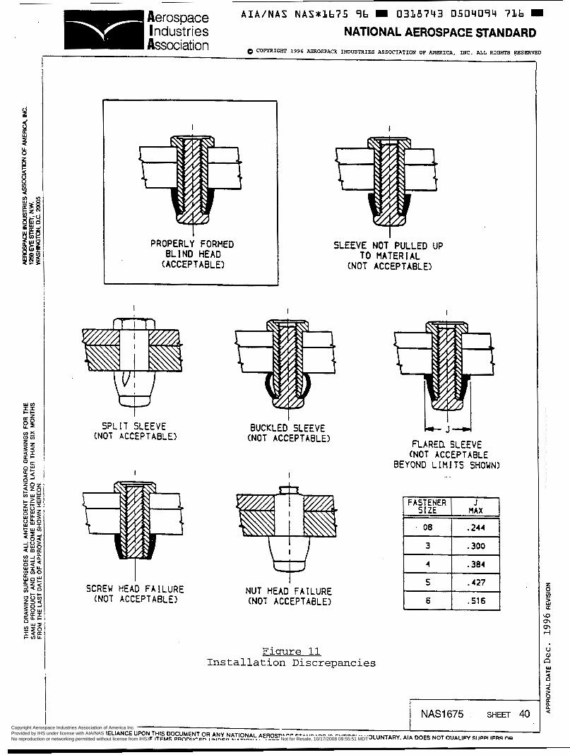
A I A / N A S NASwLb75 96 0338743 0504094 7Lb W Aerospace Industries NATIONAL AEROSPACE STANDARD Association 0 COPYRIGHT 1996 AEROSPACE INDUSTRIES ASSOCIATION OF AMERICA, INC. ALL RIGHTS FSERVBD
I
1 PROPERLY FORMED
BLIND HEAD (ACCEPTABLE)
I
SPLIT SLEEVE (NOT ACCEPTABLE)
I
SCREU HEAD FAILURE (NOT ACCEPTABLE)
I
SLEEVE NOT PULLED UP TO MATERIAL
(NOT ACCEPTABLE)
I
I BUCKLED SLEEVE
(NOT ACCEPTABLE]
I
NUT HEAD FAILURE (NOT ACCEPTABLE)
Fiqure 11 Installation Discrepancies
I
FLARED. SLEEVE (NOT ACCEPTABLE
BEYOND LIHITS SHOWN)
6 .f16
I NAS1675 SHEET 40 Copyright Aerospace Industries Association of America Inc. Provided by IHS under license with AIA/NAS Licensee=Fuerza Aerea Argentina/5969982001
Not for Resale, 10/17/2008 09:55:51 MDTNo reproduction or networking permitted without license from IHS
--``,,,`,,`,``,,`````,,```,`,,-`-`,,`,,`,`,,`---

Aerospace A I A I N A S NAS*3675 96 0338743 0504095 652 W Industries NATIONAL AEROSPACE STANDARD Association QCOPYRIGHT 1996 ABROSPACB INDUSTRIES ASSOCIATION OP AMERICA, INC. ALL RIGHTS RESERVED
Fastener Size
Flush Head
Countersink Diameter
I An i
Inch Lbs. Flush I Prot
*Measured from top o f head
of nut
Flush( Prot Flush( Prot Flush I Pro
=astener( Torque I
08 4 +.O20
3 6 +.O15
4 10 +.O10 -.O78
5 20 +.O10 -.O83
6 30 +.O10
-.O68
-.O73
Table IX Installation Criteria
+.O00 +.O82 +.O00 +.O00 +.O00 +.O20
+.O10 +.O72 +.O15 +.O10 +.O15 +.O15
+.O47 +.O72 +.O32 +.O10 +.O47 +.O10 +.135 -.O26 +.I30 +.O98 +.135 -.O78 +.O43 +.O72 +.O27 +.o1 o +.146 -.O31 +.130 -.O88 +.O49 +.O72 +.O27 +.o10
+.O88 -.O06 +.O88 +.O88 +.O88 -.O68
+.O98 -.O16 +.lo3 +.O98 +.lo3 -.O73
Millable Head
I (-.O93 1+.i521 -.O31 1+.13O1 I -.O93 I+.152
o8 I .270/.280
A *Break-Off
Protruding Head A. 1
*Measured from Skin
Surface
nits
- +.o0 +.O8 +.o1 +.o9 +.O4 +.19
- -
,+.O4 ~+. 14 pi
NAS1675 SHEm 41
USE OF OR RELIANCE UPON THIS DOCUMENT OR ANY NATIONAL AEROSPACE STANDARD IS ENTIRELY VOLUNTARY. AIA DOES NOT QUALIFY SUPPLIERS OR CERTIM CONFORMANCE OF ITEMS PRODUCED UNDER NATIONAL AEROSPACF STANnARnq AIA U A K E C un n C D a æ c f i i T * ~ m ~ * nn c* -0.. --e- --...- Copyright Aerospace Industries Association of America Inc.
Provided by IHS under license with AIA/NAS Licensee=Fuerza Aerea Argentina/5969982001 Not for Resale, 10/17/2008 09:55:51 MDTNo reproduction or networking permitted without license from IHS
--``,,,`,,`,``,,`````,,```,`,,-`-`,,`,,`,`,,`---
A I A I N A S NAS*i1675 96 E 0318743 0504096 599 E
Aerospace NAliONAL AEROSPACE STANDARD COPYRIGHT 1996 AEROSPACE INDUSTRIES ASSOCIATION OF AMERICA, INC. ALL RIGHTS RESERVED
Industries h a t i o n
4.6.14. Metalluroical Condition: Two (2) specimens out of each heat treat lot of titanium components, shall be longitudinally sectioned, mounted and microscopically examined fcr conformance to Paragraph 3.9.3. The etchant used for micro-structure shall be Kroll’s and the etchant used for alpha-case determination shall be 2% HF.
4.6.15 Hvdroaen Content: Titanium components (Class 4 nuts and screws)
4.6.15.1 Samdincr and Retest Criteria - One spechen out of every heat lot of titanium components. If hydrogen content exceeds the requirements o€ Paragraph 3 . 9 . 3 , retest five (5) additional
- specimens. If any of the additional spechents exceeds the requirement, reject the lot.
4.6.15.2 Procedure - Titanium components shall be checked for hydrogen content using procedures and equipment that are capable of analyzing hydrogen to an accuracy of .O010 percent (10 ppm). Protective treatment ( s ) and lubricant ( s ) shall be removed before testing.
. r
5. PREPARATION FOR DELIVERY
5.1 Packaaina - Fasteners shall be packaged in such a manner as to assure they will not be damaged or exposed to undue weathering or harmful materials.
5.1.1 Unit Packaging - A unit package may include fasteners of only one type, size, part number and lot number. A unit-package may contain a maximum of 100 pieces. Boxes conforming to any of the following specifications may be used:
Paper board Folding, Specification PPP-B-566, Style II.
Paper board Metal-Stayed, Specification PPP-B-665, Style C .
5 .1 .2 Shipment Packaging - Unit packages of fasteners may be consolidated into larger packages for shipment. Packages for shipment must allow economical transportation and must conform to consolidated freight classification rules.
NAS1675 42 Copyright Aerospace Industries Association of America Inc. Provided by IHS under license with AIA/NAS Licensee=Fuerza Aerea Argentina/5969982001
Not for Resale, 10/17/2008 09:55:51 MDTNo reproduction or networking permitted without license from IHS
--``,,,`,,`,``,,`````,,```,`,,-`-`,,`,,`,`,,`---

A I A / N A S NASxLb75 9b = 0338743 0504097 425 W Aerospace
Association I ndust r ¡es NATIONAL AEROSPACE STANDARD
0 COPYRIGHT 1996 AEROSPACE INDUSTRIES ASSOCIATION OF AMERICA, INC. RLL RIGHTS RESERmD
5.2 Markinq - Each unit container shall be legibly marked to give the following minimum information: Brief descriptive title, complete NAS part number, manufacturer's part number, assembly lot, manufacturer's name, trade mark and quantity in container. In addition to the special marking specified, m,it containers and shipping packages shall be marked in accordance with MIL- STD-129
6 NOTES:
6.1 Intended Use - Fasteners covered by this specification are intended for structural attachments in aerospace vehicles and associated accessories whenever access to one side of the joint is not adequate for the installation of conventional structural fasteners.
6.1.1 in applications requiring removal
It is not intended that these fasteners be employed
6.1.2 These fasteners are intended for applications where shear loads are the primary design consideration and any tensile loads are of secondary concern.
6.2 INSTALLATION TOOLS - The fasteners covered by this specification should be installed with tools recornended by the fastener producer and in accordance with the producer's instructions.
NAS1675 SHEET 43 Copyright Aerospace Industries Association of America Inc. Provided by IHS under license with AIA/NAS Licensee=Fuerza Aerea Argentina/5969982001
Not for Resale, 10/17/2008 09:55:51 MDTNo reproduction or networking permitted without license from IHS
--``,,,`,,`,``,,`````,,```,`,,-`-`,,`,,`,`,,`---