aeroelastic analysis ch601xl - zenair europe · ch601xl -1- aeroelastic analysis ch601xl m.sc....
TRANSCRIPT

CH601XL
-1-
Aeroelastic Analysis CH601XL
M.Sc. Cigdem Cakici, M.Sc. Burcak Özkök
Prof. Dr.-Ing. Uwe Weltin Institute for Reliability Engineering
* * * * *
Hamburg University of Technology (TUHH)
Figure 1: Ground Vibration Test CH601XL

CH601XL
-2-
Table of contents
1. TASK DESCRIPTION ...............................................................................................2
2. GROUND VIBRATION TEST....................................................................................3
3. FLUTTER CALCULATION CH601XL.....................................................................14
4. FLUTTER RESULTS FOR THE CH601XL .............................................................21
5. SUMMARY..............................................................................................................22
6. ASSUMPTIONS AND FINAL REMARKS...............................................................23
7. REMARKS AND RECOMMENDATIONS ON AILERON MASS BALANCING AND SPADES..................................................................................................................26
1. Task description In this paper, linear aeroelastic investigations on the flutter stability of the aircraft CH601XL are documented in order to show compliance with the requirements of JAR-23. With a complete Ground Vibration Test (GVT) and flutter calculations based on the modal values found in the GVT, linear flutter stability has to be shown up to a true airspeed (TAS) of as much as 120% of the design speed (1.2*VD). The flutter calculation was initially worked out for the airplane with minimum take-off mass (Empty: No luggage, no fuel, one pilot), free controls and fixed controls at sea level. After this, flutter calculations with maximum take-off weight (pilot and copilot, maximum amount of fuel and maximum luggage), blocked and freed controls at sea level were performed. To show aeroelastic effects of manufacturing tolerances in the ailerons, additional mass points was added to the trailing edge of the ailerons and all previous calculations were repeated. As a last task, the feasibility and desirability of aileron mass balancing was evaluated as a potential modification for the CH601XL. A number of calculations were also made for high-altitude (5,000m) flights for different mass configurations of the CH601XL. The methods used here to calculate the flutter speed of an aircraft are based on Finite Element Analysis (FEA) and have been verified and validated with several wind tunnel tests3. The methods used for the evaluation of the time series resulting from the ground vibration tests (GVT) have been verified and validated with both FEA results and experiments4. 13 Uwe Weltin, Berechnung und Überprüfung der Flattergeschwindigkeit eines Flügelstreifens im Winkanal des DLR_School_Lab der TUHH, Interne Berichte des Institutes für Zuverlässigkeitstechnik an der TUHH, 2004 . 4 Swantje Johnson, Dynamische Strukturanalyse einer Aluminiumplatte, Institut für Zuverlässigkeitstechnik an der Technischen Universität Hamburg, August 2007.

CH601XL
-3-
2. Ground Vibration Test To carry out the vibration tests (GVT), the CH601XL aircraft was equipped with as many as 78 accelerometers (see Figure 2) and suspended from the ceiling of the hangar (see figure 1).
Figure 2: Node numbers for accelerometers and synthetic mass perturbation

CH601XL
-4-
The springs of the suspension have an effective stiffness of Cs = 39 kN/m. The CH601XL in its minimal mass configuration loads 385 kg. The highest rigid body resonance frequency (vertical movement of the total airplane) in its elastic suspension therefore is
• FR1 = 1.6 Hz. The other rigid body Eigen frequencies of the aircraft are all at considerably lower values. Because the lowest structural mode shapes of the aircraft need to be captured accurately enough, all rigid body natural frequencies have to lie significantly below the first structural Eigen frequency. The first wing bending Eigen frequency is determined at
• FS1 = 10.3 Hz so that the required frequency spacing is fulfilled. For a complete GVT multiple multi shaker configurations have to be used in order to be able to identify all relevant natural modes. Figure 3 shows the shaker configurations for the identification of the control modes of the CH601XL.
Figure 3: Shaker configurations for the identification of the control modes of the CH601XL
Figure 4 shows the shaker configurations for the identification of the structural modes of the CH601XL.

CH601XL
-5-
Figure 4: Shaker configurations for the identification of the structural modes of the CH601XL
2.1 Modal data from GVT for CH601XL with minimum take off mass and fixed controls
After evaluating the measurements of the ground vibration test for the CH601XL with minimum take off mass and fixed controls the values for the Eigen frequencies, the generalized masses and modal damping are obtained. The value PRC (Phase Resonance Criterion) is one of the two quality indicators used in this report. If the value PRC is better than 95% the excitation of the corresponding Eigen modes was successful. For PRC values smaller the 80% another measurement with shaker positions in the antinodes of an actual mode is advised. In order to work out robust flutter margins with respect to the possible variances of control cable tension of the airplane in service, a total of four modal measurements are performed for the CH601XL (see Tables 1 to 3). A second indication for the quality of the GVT- evaluation is the Modal Assurance Criterion which shows the result of the orthogonality of the Eigen modes found with the ground vibration test (see Figures 5 to7).

CH601XL
-6-
Table 1: Modal data from GVT for CH601XL with minimum take off weight and fixed controls, control cables adjusted to 5 lbs

CH601XL
-7-
Figure 5: Modal assurance criterion matrix (MAC) for the Eigen vectors evaluated from the time series of the ground vibration test for the CH601XL with minimum take off weight and fixed controls, control cables adjusted to 5 lbs.

CH601XL
-8-
Table 2: Modal data from GVT for CH601XL with minimum take off weight and fixed controls, control cables adjusted to 30 lbs

CH601XL
-9-
Figure 6: Modal assurance criterion matrix for the Eigen vectors evaluated from the time series of the ground vibration test for the CH601XL with minimum take off weight and fixed controls, control cables adjusted to 30 lbs.

CH601XL
-10-
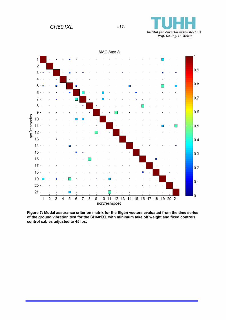
Table 3: Modal data from GVT for CH601XL with minimum take off weight and fixed controls, control cables adjusted to 45 lbs.
CH601XL
-11-
Figure 7: Modal assurance criterion matrix for the Eigen vectors evaluated from the time series of the ground vibration test for the CH601XL with minimum take off weight and fixed controls, control cables adjusted to 45 lbs.
CH601XL
-12-
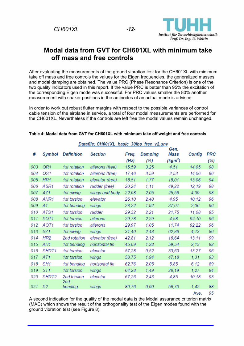
Modal data from GVT for CH601XL with minimum take off mass and free controls
After evaluating the measurements of the ground vibration test for the CH601XL with minimum take off mass and free controls the values for the Eigen frequencies, the generalized masses and modal damping are obtained. The value PRC (Phase Resonance Criterion) is one of the two quality indicators used in this report. If the value PRC is better than 95% the excitation of the corresponding Eigen mode was successful. For PRC values smaller the 80% another measurement with shaker positions in the antinodes of an actual mode is advised. In order to work out robust flutter margins with respect to the possible variances of control cable tension of the airplane in service, a total of four modal measurements are performed for the CH601XL. Nevertheless if the controls are left free the modal values remain unchanged. Table 4: Modal data from GVT for CH601XL with minimum take off weight and free controls
A second indication for the quality of the modal data is the Modal assurance criterion matrix (MAC) which shows the result of the orthogonality test of the Eigen modes found with the ground vibration test (see Figure 8).

CH601XL
-13-
Figure 8: Modal assurance criterion matrix for the Eigen vectors evaluated from the time series of the GVT for the CH601XL with minimum take off mass and free controls.

CH601XL
-14-
3. Flutter calculation CH601XL
To calculate the critical flight speed, which indicates the beginning of a possible flutter phenomenon the aeroelastic model of CH601XL must be established. The entire surface of the airplane is discretized with Doublet Lattice Elements (DLE) with the corresponding module of the software package ZAERO5. Figure 10 shows the results of this modeling.
Figure 9: Aeroelastic Model of the CH601XL
After modeling the skin of the airplane the natural vibration modes identified in the time series evaluation from the ground vibration test are imported into the ZAERO program. Each vibration mode is connected to the DLE elements of the aircrafts surface by three dimensional splining methods. The result of this procedure is exported from ZAERO for each mode using standard data sets to allow the printing or animation of these modes. In this work the IDEAS standard universal file format is used. The animation and the images of the modes are produced with the MATLAB toolbox SDTools6. The structural dynamic toolbox SDTools allows both, FEA calculations and time series analysis. The first three splined natural modes out of 18 for the CH601XL with controls fixed and cable tension adjusted to the nominal value are shown in Figures 11 through 13. The first three splined natural modes out of 18 for the CH601XL with controls fixed and cable tension adjusted to a value al low as 5 lbs are shown in Figures 14 through 16.The rest of the natural modes for nominal control cable tension as well as for low cable tensions (5 lbs and 15 lbs) and higher cable tension (45 lbs) can be found on the project- DVD as JPG- files and UNV- Files together with the corresponding MATLAB animation source codes.
5 ZAERO, Users manual, Version 8.2, March 2008, www.zonatech.com, downloadable PDF 6 SDTools, Users manual , Version 6.0, 2008, www.sdtools.com, downloadable PDF

CH601XL
-15-
Figure 10: First natural mode of the CH601XL with minimum take off weight, controls fixed and
cable tension adjusted to the nominal value 30lbs
Figure 11: Second natural mode of the CH601XL with minimum take off weight, controls fixed
and cable tension adjusted to the nominal value 30lbs

CH601XL
-16-
Figure 12: Third natural mode of the CH601XL with minimum take off weight, controls fixed and
cable tension adjusted to the nominal value 30lbs
Figure 13: First natural mode of the CH601XL with minimum take off weight, controls fixed and
cable tension adjusted to 5lbs

CH601XL
-17-
Figure 14: Second natural mode of the CH601XL with minimum take off weight, controls fixed
and cable tension adjusted to 5lbs
Figure 15: Third natural mode of the CH601XL with minimum take off weight, controls fixed and
cable tension adjusted to 5lbs

CH601XL
-18-
As can bee seen from Figure 12 and Figure 13 the symmetric aileron mode changes significantly its Eigen frequency if the control cable tension is reduced from the nominal value 30 lbs to 5 lbs. Nevertheless the airspeed dependent aerodynamic damping of the corresponding flutter calculations remain positive as can be seen from Figure 16 and Figure 17.
Figure 16: Aerodynamic damping for the CH601XL with minimum take off mass and blocked
controls (aileron, elevator and rudder) at low altitude flight from 60 km/h up to 500 km/h. Control cable tension adjusted to the nominal value (30 lbs).

CH601XL
-19-
Figure 17: Aerodynamic damping for the CH601XL with minimum take off mass and blocked
controls (aileron, elevator and rudder) at low altitude flight from 60 km/h up to 500 km/h. Control cable tension adjusted to a very low value (15 lbs).
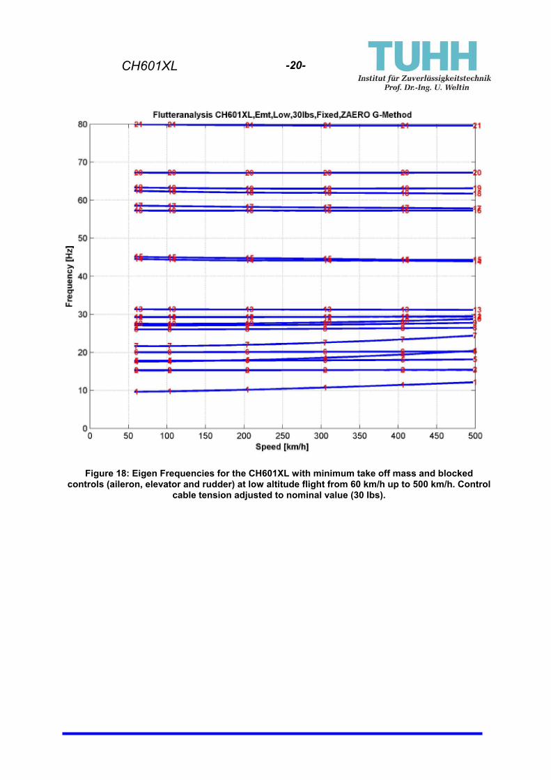
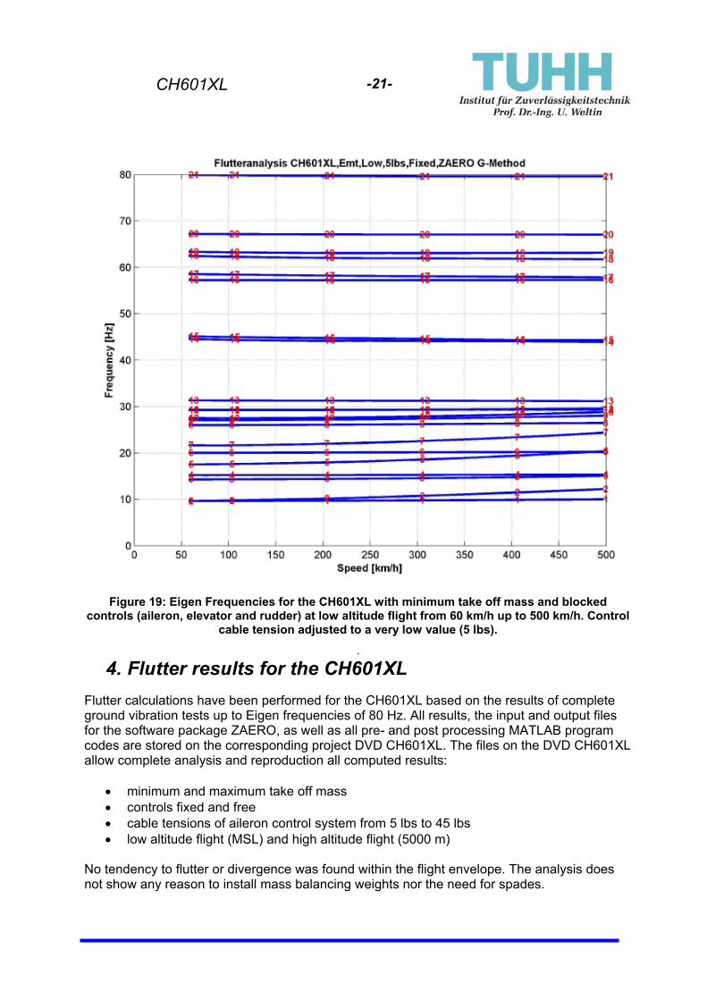
As shown in Figure 18 and Figure 19 the airspeed dependent Eigen frequencies of the aileron modes (Mode 2 and Mode 3 in Figure 18, Mode 1 and Mode 3 in Figure 19)7 are reduced significantly only at low air speed. At higher airspeed the aileron control in both cases appears to become stiffer. This is the usual experience of a pilot in flight.
7 The frequencies in ZAERO are sorted with respect to their values in ascending order
CH601XL
-20-
Figure 18: Eigen Frequencies for the CH601XL with minimum take off mass and blocked
controls (aileron, elevator and rudder) at low altitude flight from 60 km/h up to 500 km/h. Control cable tension adjusted to nominal value (30 lbs).
CH601XL
-21-
Figure 19: Eigen Frequencies for the CH601XL with minimum take off mass and blocked
controls (aileron, elevator and rudder) at low altitude flight from 60 km/h up to 500 km/h. Control cable tension adjusted to a very low value (5 lbs).
.
4. Flutter results for the CH601XL Flutter calculations have been performed for the CH601XL based on the results of complete ground vibration tests up to Eigen frequencies of 80 Hz. All results, the input and output files for the software package ZAERO, as well as all pre- and post processing MATLAB program codes are stored on the corresponding project DVD CH601XL. The files on the DVD CH601XL allow complete analysis and reproduction all computed results:
• minimum and maximum take off mass • controls fixed and free • cable tensions of aileron control system from 5 lbs to 45 lbs • low altitude flight (MSL) and high altitude flight (5000 m)
No tendency to flutter or divergence was found within the flight envelope. The analysis does not show any reason to install mass balancing weights nor the need for spades.

CH601XL
-22-
5. Summary JAR-23 guidelines require testing to ensure that “the airplane is free from flutter, control reversal and divergence for any condition of operation within the limit V~n envelope”. With the classical linear approach for flutter analysis with ground vibration test and up to date flutter calculations using the software package ZAERO, no aeroelastic instability was found within the flight envelope of the CH601XL. When the flap stops are installed according to the manufacturer's specifications is mounted and the cable tensions are within the specified tolerances set by the manufacturer, the occurrence of flutter with the CH601XL is improbable within the well defined flight envelope. The analysis in this report is based on linear methodology. The analysis of possible nonlinear vibrations due to structural instabilities was not the subject of this investigation.

CH601XL
-23-
6. Assumptions and Final Remarks In order to insure that the flutter results worked out in this report will be valid, the authors assume that the following conditions will be in place: 1. All control cable tensions will be set and maintained as per manufacturer’s specifications.
Figure 20: Adjusting control cable tension (see XLphotoguide.pdf)
2. The flap gap stops for the retracted landing flaps (see Figure 21) must be installed
Figure 21: Flap gap stop, Part No. 6S3-1
Flap Gap Stop

CH601XL
-24-
3. Aircraft must be operated within specified speed limitations as set out by the manufacturer. This includes VF, VA, VC and VNE (see Flight Manual or plans for details).
Figure 22: Speed limits (extract from front page of CH601XL plans)

CH601XL
-25-
4. Aileron deflections measured at the hinge axis must all be kept within the specified values. Control stop(s) must be installed as per manufacturer specifications to ensure deflections remain within acceptable ranges (see Figure 23 for example).
Figure 23: One acceptable aileron-stop design (as per LTF-UL certified CH 601 XL)

CH601XL
-26-
7. Remarks and recommendations on Aileron Mass Balancing and Spades
A number of individual Zodiac owners as well as government agencies have recommended the installation of traditional aileron mass balancing as a means to mitigate any risk of flutter with the Zodiac design. Based on the standard airframe design examined and on the GVT results and linear approach of the flutter analysis documented in this report, mass balancing for the ailerons of the CH601XL (see example Figure 24) or the use of spades (see Figure 25) is not needed or justified.
Figure 24: Proposal for mass balancing
Figure 25: Proposal for spades

CH601XL
-27-
While mass balancing of the ailerons is generally believed to prevent flutter, the extra weight associated with control-surface mass balancing could have negative consequences if not properly designed and/or supported. It is possible that modifications to the standard control system and/or basic airframe structure of the Zodiac could be necessary to properly install aileron mass balancing on the CH650E. As any new modification (such as mass balancing) can potentially be associated with new “randomly excited non-linear vibrations”, it must therefore be “sound” (sensible) through logic and reasoning and effective as demonstrated through testing. Sometimes, if one does not know exactly what one is doing, one can make matters worse with a well-intentioned modification to an aircraft.
Hamburg, June 6, 2009
Prof. Dr.-Ing. Uwe Weltin