aerodynamic characteristics of diamond shaped … · supersonic speeds as compared to circular...
TRANSCRIPT
International Journal of Aerospace and Mechanical Engineering
Volume 5 – No.2, April 2018
19
ISSN (O): 2393-8609
AERODYNAMIC CHARACTERISTICS OF DIAMOND
SHAPED AIRFOIL AT SUPERSONIC SPEED
Aditya Pratap Singh Rathore Student (B.E Aerospace)
Chandigarh University
ABSTRACT
In this paper, I investigated the flow over a “Diamond shaped
Airfoil” in terms of Lift, Drag, L/D ratio and flow velocity
over it at supersonic speed, Mach 2 at different angle of
attacks. Diamond Airfoils experience lower drags at supersonic speeds as compared to circular Airfoils. Diamond
airfoils can be proved to be more efficient Airfoils than other
Airfoils at supersonic speeds. Hence it is very important to
study the Aerodynamic characteristics of the Diamond Airfoil as it can solve the problem of high drag at supersonic speeds.
I compared the flow parameters between three diamond
shaped airfoil having different geometries by using one of the
best computational fluid simulation software, ANSYS Workbench and Catia V5 for modelling.
Keywords
Diamond Airfoil, Supersonic Airfoil, Hypersonic Airfoil,
Aerodynamic, Airfoil, Angle of Attack, Lift and Drag, Mach
number, computational fluid dynamics, CFD, ANSYS simulation.
1. INTRODUCTION An Airfoil (American English) or Aerofoil (British English) is
the shape of a wing, blade (of a propeller, rotor, or turbine), or
sail (as seen in cross-section).
An airfoil-shaped body moved through a fluid produces an
aerodynamic force. The component of this force perpendicular
to the direction of motion is called lift. The component
parallel to the direction of motion is called drag.
The lift on an airfoil is primarily the result of its angle of
attack and shape. When oriented at a suitable angle, the airfoil
deflects the oncoming air (for fixed-wing aircraft, a
downward force), resulting in a force on the airfoil in the direction opposite to the deflection. This force is known as
aerodynamic force and can be resolved into two components:
lift and drag. Most foil shapes require a positive angle of
attack to generate lift, but cambered airfoils can generate lift at zero angle of attack. This "turning" of the air in the vicinity
of the airfoil creates curved streamlines, resulting in lower
pressure on one side and higher pressure on the other. This
pressure difference is accompanied by a velocity difference, via Bernoulli's principle, so the resulting flow field about the
airfoil has a higher average velocity on the upper surface than
on the lower surface. The lift force can be related directly to
the average top/bottom velocity difference without computing the pressure by using the concept of circulation and the Kutta-
Joukowski theorem.
The primary purpose of an airfoil is to produce lift when
placed in a fluid stream which of course experience drag at the same time. In an aircraft, lift on the wing surfaces
maintains the aircraft in the air and drag absorbs all the engine
power necessary for forward motion of the craft. In order to
minimize drag, an airfoil is a streamlined body. The ratio of
lift to drag gives a measure of the usefulness of an airfoil as a
wing section of an aircraft. The higher this ratio the better the airfoil since it is capable of producing high lift at a small drag
penalty. The ratio of lift to drag is expressed as 𝐿/𝐷 ratio or
𝐶𝐿/𝐶𝐷 ratio and can be determined by computational
methods. If this ratio is high, then the airfoil can be used to produce useful lift which makes the aircraft to fly. An aircraft
has a high 𝐿/𝐷 ratio or 𝐶𝐿/𝐶𝐷 ratio if it produces a large
amount of lift or a small amount of drag.
2. METHODOLOGY
Theoretical considerations 2.1.2 Thin Airfoil Theory
Thin airfoil theory is a simple theory of airfoils that relates
angle of attack to lift for incompressible, inviscid flows. It
was devised by German-American mathematician Max Munk
and further refined by British aerodynamicist Hermann
Glauert and others in the 1920s. The theory idealizes the flow
around an airfoil as two-dimensional flow around a thin
airfoil. It can be imagined as addressing an airfoil of zero
thickness and infinite wingspan. Thin airfoil theory was
particularly notable in its day because it provided a sound
theoretical basis for the following important properties of
airfoils in two-dimensional flow:
1. On a symmetric airfoil, the center of pressure and
aerodynamic center lies exactly one quarter of the chord
behind the leading edge.
2. On a cambered airfoil, the aerodynamic center lies exactly
one quarter of the chord behind the leading edge.
3. The slope of the lift coefficient versus angle of attack line is
2π units per radian.
As a consequence, the section lift coefficient of a symmetric
airfoil of infinite wingspan is:
Cl = 2*π*α
where Cl is the section lift coefficient
α is the angle of attack in radians, measured relative to the
chord line.
3. COMPUTATIONAL METHOD
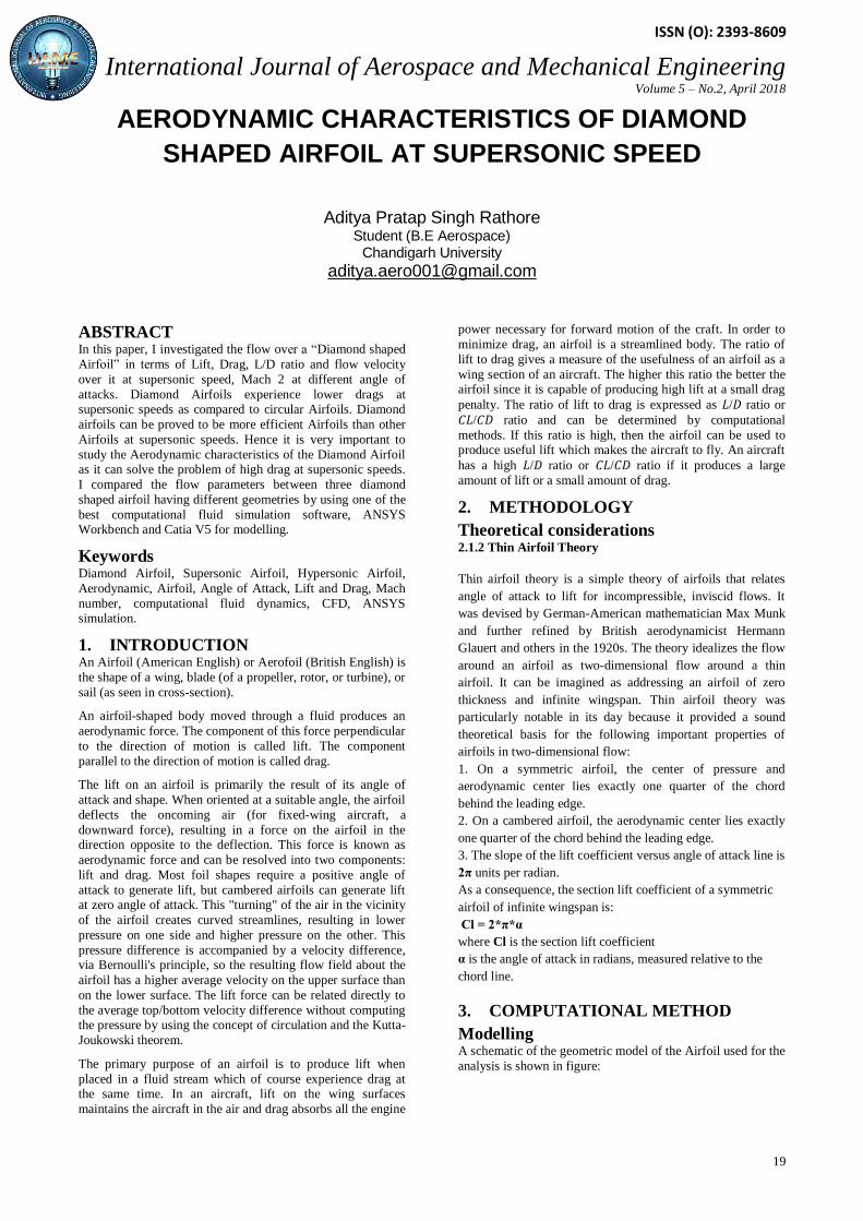
Modelling A schematic of the geometric model of the Airfoil used for the
analysis is shown in figure:
International Journal of Aerospace and Mechanical Engineering
Volume 5 – No.2, April 2018
20
ISSN (O): 2393-8609
Airfoil
Name
Angle 1 Angle 2 Angle 3 Angle 4
A 20 160 20 160
B 10 170 10 170
C 05 175 05 175
To make this geometry, I used CatiaV5 using generative
shape design module. The cord of the Airfoil is 140.034mm. I
varied the geometry of the Airfoil by changing the angles of
the Diamond geometry--the upper and lower angles namely 160 deg, 170 deg, 175 deg.
Simulation The simulation was done using the FLUENT over the ANSYS
Workbench. I used the pressure based solver and time steady
planar method. The model used was Sparlat-Allamaras(1eqn.). The fluid used is air and the material of the
airfoil is the Aluminum. The ell zone conditions were kept as
default. Now regarding the Boundary conditions, the inlet was set as a velocity inlet type with the value of Mach 2(686m/s).
The outlet was set as pressure outlet with the default values.
The solution methods were- the simple scheme for pressure
velocity coupling. Least squares cell based, Second order upwind momentum for the spatial discretization. Monitors for
the CL and CD plot. Hybrid settings for the solution
initialization. Did run the iterations till the solution got
converged.
4. RESULTS AND DISCUSSIONS I analyzed the flow over three types of Diamond shaped
airfoils. I took the airfoils changing the upper and lower
angles-160 deg.170 deg.175 deg. with a negligible change in
chord length. As shown in the figures
.
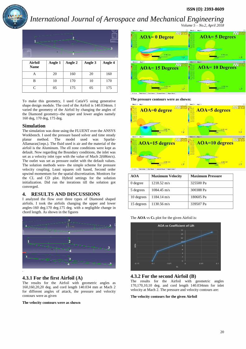
4.3.1 For the first Airfoil (A) The results for the Airfoil with geometric angles as 160,160,20,20 deg. and cord length 140.034 mm at Mach 2
for different angles of attack, the pressure and velocity
contours were as given
The velocity contours were as shown
The pressure contours were as shown:
AOA Maximum Velocity Maximum Pressure
0 degree 1218.52 m/s 325500 Pa
5 degrees 1084.45 m/s 300388 Pa
10 degrees 1184.14 m/s 180605 Pa
15 degrees 1130.56 m/s 339507 Pa
The AOA vs CL plot for the given Airfoil is:
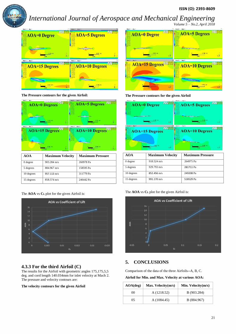
4.3.2 For the second Airfoil (B) The results for the Airfoil with geometric angles
170,170,10,10 deg. and cord length 140.034mm for inlet
velocity at Mach 2. The pressure and velocity contours are:
The velocity contours for the given Airfoil
International Journal of Aerospace and Mechanical Engineering
Volume 5 – No.2, April 2018
21
ISSN (O): 2393-8609
The Pressure contours for the given Airfoil:
AOA Maximum Velocity Maximum Pressure
0 degree 903.284 m/s 260978 Pa
5 degrees 884.967 m/s 158595 Pa
10 degrees 957.113 m/s 311779 Pa
15 degrees 858.574 m/s 246442 Pa
The AOA vs CL plot for the given Airfoil is:
4.3.3 For the third Airfoil (C) The results for the Airfoil with geometric angles 175,175,5,5
deg. and cord length 140.034mm for inlet velocity at Mach 2.
The pressure and velocity contours are:
The velocity contours for the given Airfoil
The Pressure contours for the given Airfoil
AOA Maximum Velocity Maximum Pressure
0 degree 918.524 m/s 264975 Pa
5 degrees 929.793 m/s 281711 Pa
10 degrees 852.456 m/s 249208 Pa
15 degrees 991.170 m/s 518529 Pa
The AOA vs CL plot for the given Airfoil is:
5. CONCLUSIONS Comparison of the data of the three Airfoils--A, B, C.
Airfoil for Min. and Max. Velocity at various AOA:
AOA(deg) Max. Velocity(m/s) Min. Velocity(m/s)
00 A (1218.52) B (903.284)
05 A (1084.45) B (884.967)

International Journal of Aerospace and Mechanical Engineering
Volume 5 – No.2, April 2018
22
ISSN (O): 2393-8609
10 A (1184.14) C (852.456)
15 A (1130.56) B (858.574)
Airfoil for Min. and Max. Pressure at various AOA:
AOA(deg) Max. Pressure(Pa) Min. Pressure(Pa)
00 A (325500) B (260978)
05 A (300388) B (158595)
10 B (311779) A (180605)
15 C (518529) B (246442)
5.1 DRAG POLAR FOR THE AIRFOILS:
Airfoil A
Airfoil B
Airfoil C
5.2 VERDICT It is clear from the above comparison tables that, the Airfoil A
gives the best result and the Airfoil B gives the worst result
among these Airfoils, when it comes to the matter of speed.
But, when it comes to the matter of Lift and Aerodynamic
efficiency, then according to the Drag polar of the Airfoils,
Airfoil C gives the best result.
6. REFERENCES [1]. Anderson (2001). Fundamentals of Aerodynamics,
McGraw-Hill Companies, Inc. New York, 3rd edition, 437-
650.
[2]. Auld D. J. and Srinivas K. (2010). Aerodynamics for
students. Aerospace, Mechanical and Mechatronic
Engineering, University of Sydney.
[3]. Bertin J. J., Cummings R. M. (2009). Aerodynamics for
Engineers. Pearson Prentice Hall Ed. (5th Ed.).
[4]. Cavcar M. (2012). Pressure distribution around an airfoil,
March 5, 2012 http://home.anadolu.edu.tr/~mcavcar/hyo30
1/14_PressureDistribution.pdf 7. Douglas J. F. (2000). Fluid
Mechanics. Pitman Publishing New Zealand Ltd.
[5]. Gas Dynamics (sixth edition), Ethirajan Rathakrishnan.
PHI Learning Private Limited, Delhi, 110092.
[6]. Houghton, E. L., Carpenter, P. W. (2003). Aerodynamics for Engineering Students. Butterworth Heinmann.
[7]. Karabelas S. J. and Markatos N. C. (2008). Water Vapour
Condensation in Forced Convection Flow over an Airfoil, Aerospace Science and Technology, 12(2): 150 - 158.
[8]. Munson R. B., Donald F. Y., Theodore H. O. (2005).
Fundamentals of Fluid Mechanics, 5th edition.
[9]. PrabhakarRao P. and Sampath S. V. (2014). CFD
Analysis on Airfoil at High Angles of Attack. International
Journal of Engineering Research, 3(7): 430 - 4343. 12