aero-thermal research particulars in ultra-micro gas … educational notes/rto-en... ·...
TRANSCRIPT
RTO-EN-AVT-131 3 - 1
Aero-Thermal Research Particulars in Ultra-Micro Gas Turbines
Toshio NAGASHIMA and Susumu TERAMOTO Department of Aeronautics and Astronautics
University of Tokyo 7-3-1, Hongo, Bunkyo
Tokyo 113-8656 JAPAN
Chisachi KATO Institute of Industrial Sciences
University of Tokyo JAPAN
Saburo YUASA Department of Aerospace Engineering
Tokyo Metropolitan Institute of Technology Asahigaoka 6-6 Hino City
Tokyo 191-0065 JAPAN
ABSTRACT
Aerodynamics in turbo-components and matched combustor characteristics relating to the design of ultra-micro gas turbines (UMGT) were presented. Some detailed analysis were provided for the effects of heat transfer, tip clearance and geometrical restriction imposed to UMGT flow passages, as well as a leading concept of combustor design to achieve micro flame structure for enhanced efficiency and stability.
1. INTRODUCTION
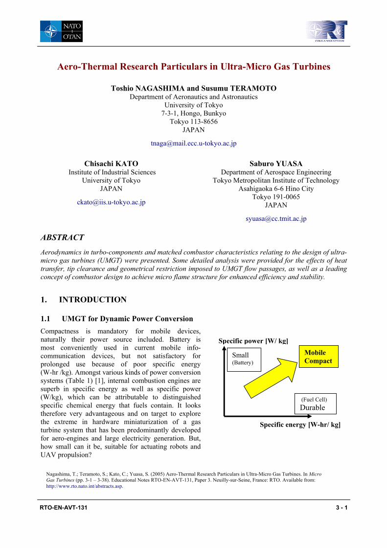
1.1 UMGT for Dynamic Power Conversion Compactness is mandatory for mobile devices, naturally their power source included. Battery is most conveniently used in current mobile info-communication devices, but not satisfactory for prolonged use because of poor specific energy (W-hr /kg). Amongst various kinds of power conversion systems (Table 1) [1], internal combustion engines are superb in specific energy as well as specific power (W/kg), which can be attributable to distinguished specific chemical energy that fuels contain. It looks therefore very advantageous and on target to explore the extreme in hardware miniaturization of a gas turbine system that has been predominantly developed for aero-engines and large electricity generation. But, how small can it be, suitable for actuating robots and UAV propulsion?
(Fuel Cell)Durable
Small (Battery)
Mobile Compact
Specific power [W/ kg]
Specific energy [W-hr/ kg]
Nagashima, T.; Teramoto, S.; Kato, C.; Yuasa, S. (2005) Aero-Thermal Research Particulars in Ultra-Micro Gas Turbines. In Micro Gas Turbines (pp. 3-1 – 3-38). Educational Notes RTO-EN-AVT-131, Paper 3. Neuilly-sur-Seine, France: RTO. Available from: http://www.rto.nato.int/abstracts.asp.
Aero-Thermal Research Particulars in Ultra-Micro Gas Turbines
3 - 2 RTO-EN-AVT-131
Meanwhile, an innovative concept of Power-MEMS turbines was proposed by MIT [2] in 1997, since then a lot of work relating to MEMS fabrication technology have been made to achieve miniaturization in gas turbines to such an extent as competitive size with disposal batteries, even smaller as a shirt button.
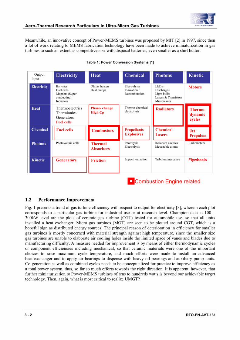
Table 1: Power Conversion Systems [1]
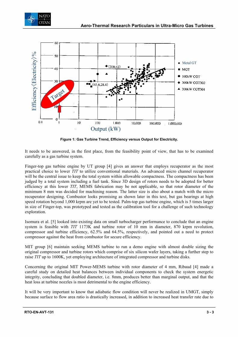
1.2 Performance Improvement Fig. 1 presents a trend of gas turbine efficiency with respect to output for electricity [3], wherein each plot corresponds to a particular gas turbine for industrial use or at research level. Champion data at 100 – 300kW level are the plots of ceramic gas turbine (CGT) tested for automobile use, so that all units installed a heat exchanger. Micro gas turbines (MGT) are seen to be plotted around CGT, which is a hopeful sign as distributed energy sources. The principal reason of deterioration in efficiency for smaller gas turbines is mostly concerned with material strength against high temperature, since the smaller size gas turbines are unable to elaborate air cooling holes inside the limited space of vanes and blades due to manufacturing difficulty. A measure needed for improvement is by means of either thermodynamic cycles or component efficiencies including mechanical, so that ceramic materials were one of the important choices to raise maximum cycle temperature, and much efforts were made to install an advanced heat exchanger and to apply air bearings to dispense with heavy oil bearings and auxiliary pump units. Co-generation as well as combined cycles needs to be conceptualized for practice to improve efficiency as a total power system, thus, so far so much efforts towards the right direction. It is apparent, however, that further miniaturization to Power-MEMS turbines of tens to hundreds watts is beyond our achievable target technology. Then, again, what is most critical to realize UMGT?
Output Input
Electricity
Heat
Chemical Photons Kinetic
Electricity
Batteries Fuel cells Magnets (Super-conducting) Inductors
Ohmic heaters Heat pumps
Electrolysis Ionization / Recombination
LED s Discharges Light bulbs Lasers & Transistors Microwaves
Motors
Heat
Thermoelectrics Thermionics Generators Fuel cells
Phase- change High Cp
Thermo-chemical electrolysis
Radiators
Thermo-dynamic cycles
Chemical
Fuel cells Combustors
Propellants Explosives
Chemical Lasers
Jet Propulsion
Photons
Photovoltaic cells
Thermal Absorbers
Photolysis Electrolysis
Resonant cavities Metastable atoms
Radiometers
Kinetic
Generators
Friction
Impact ionization
Triboluminescence
Flywheels
Combustion Engine related
Aero-Thermal Research Particulars in Ultra-Micro Gas Turbines
R
Ic
Fpwjemrsie
Iscc
Mor
Ccih
Ib
TO-EN-AVT-131 3 - 3
Figure 1: Gas Turbine Trend, Efficiency versus Output for Electricity.
t needs to be answered, in the first place, from the feasibility point of view, that has to be examined arefully as a gas turbine system.
inger-top gas turbine engine by UT group [4] gives an answer that employs recuperator as the most ractical choice to lower TIT to utilize conventional materials. An advanced micro channel recuperator ill be the central issue to keep the total system within allowable compactness. The compactness has been
udged by a total system including a fuel tank. Since 3D design of rotors needs to be adopted for better fficiency at this lower TIT, MEMS fabrication may be not applicable, so that rotor diameter of the inimum 8 mm was decided for machining reason. The latter size is also about a match with the micro
ecuperator designing. Combustor looks promising as shown later in this text, but gas bearings at high peed rotation beyond 1,000 krpm are yet to be tested. Palm-top gas turbine engine, which is 5 times larger n size of Finger-top, was prototyped and tested as the calibration tool for a challenge of such technology xploration.
somura et al. [5] looked into existing data on small turbocharger performance to conclude that an engine ystem is feasible with TIT 1173K and turbine rotor of 10 mm in diameter, 870 krpm revolution, ompressor and turbine efficiency, 62.5% and 64.5%, respectively, and pointed out a need to protect ompressor against the heat from combustor for secure efficiency.
IT group [6] maintain seeking MEMS turbine to run a demo engine with almost double sizing the riginal compressor and turbine rotors which comprise of six silicon wafer layers, taking a further step to aise TIT up to 1600K, yet employing architecture of integrated compressor and turbine disks.
oncerning the original MIT Power-MEMS turbine with rotor diameter of 4 mm, Ribaud [4] made a areful study on detailed heat balances between individual components to check the system energetic ntegrity, concluding that doubled diameter, i.e. 8mm, produces better than marginal output, and that the eat loss at turbine nozzles is most detrimental to the engine efficiency.
t will be very important to know that adiabatic flow condition will never be realized in UMGT, simply ecause surface to flow area ratio is drastically increased, in addition to increased heat transfer rate due to
Target
Target
Output (kW)
Metal GT
Effic
ienc
y(El
ectri
city
)%
Aero-Thermal Research Particulars in Ultra-Micro Gas Turbines
3 - 4 RTO-EN-AVT-131
flows at small Reynolds number. To maximize output for given fuel input, the key for feasibility exists in heat management relating the engine architecture, which is crucial and indispensable. The current knowledge about similarity rules between flow dynamics and heat transfer may have to be re-examined to apply for precise prediction, control and improvement of UMGT performance.
2. RADIAL TURBO COMPONENT PARTICULARS
2.1 Micro Radial Turbo-Flows
2.1.1 Conventional Radial Turbo-Flows
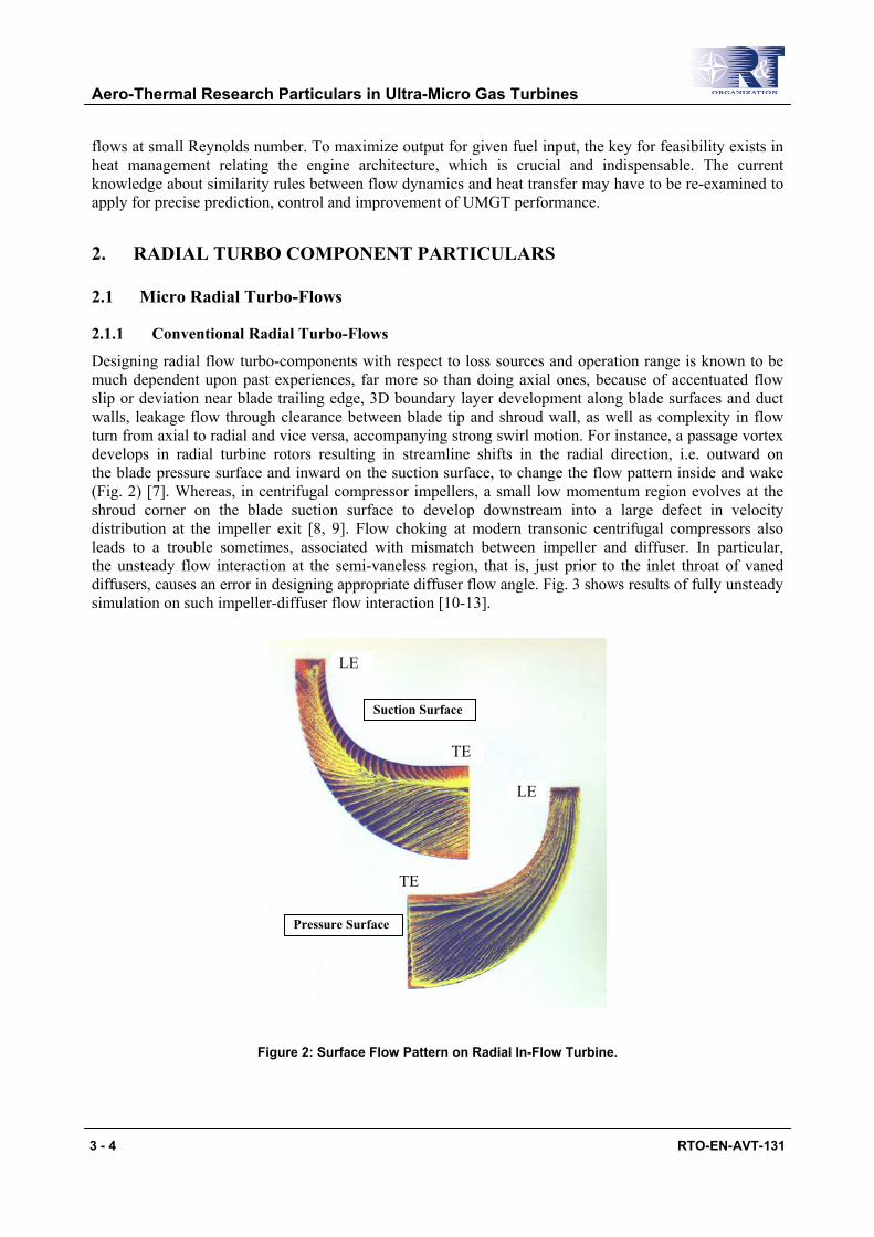
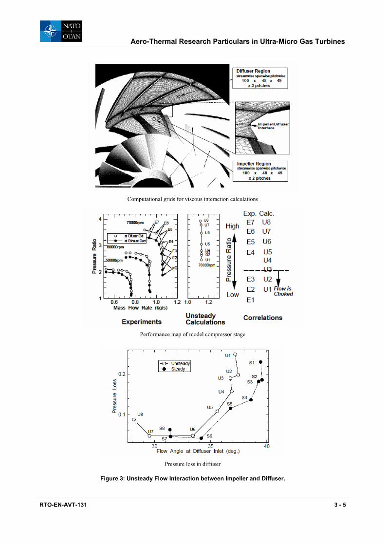
Designing radial flow turbo-components with respect to loss sources and operation range is known to be much dependent upon past experiences, far more so than doing axial ones, because of accentuated flow slip or deviation near blade trailing edge, 3D boundary layer development along blade surfaces and duct walls, leakage flow through clearance between blade tip and shroud wall, as well as complexity in flow turn from axial to radial and vice versa, accompanying strong swirl motion. For instance, a passage vortex develops in radial turbine rotors resulting in streamline shifts in the radial direction, i.e. outward on the blade pressure surface and inward on the suction surface, to change the flow pattern inside and wake (Fig. 2) [7]. Whereas, in centrifugal compressor impellers, a small low momentum region evolves at the shroud corner on the blade suction surface to develop downstream into a large defect in velocity distribution at the impeller exit [8, 9]. Flow choking at modern transonic centrifugal compressors also leads to a trouble sometimes, associated with mismatch between impeller and diffuser. In particular, the unsteady flow interaction at the semi-vaneless region, that is, just prior to the inlet throat of vaned diffusers, causes an error in designing appropriate diffuser flow angle. Fig. 3 shows results of fully unsteady simulation on such impeller-diffuser flow interaction [10-13].
Figure 2: Surface Flow Pattern on Radial In-Flow Turbine.
Suction Surface
Pressure Surface
LE
LE
TE
TE
Aero-Thermal Research Particulars in Ultra-Micro Gas Turbines
RTO-EN-AVT-131 3 - 5
Computational grids for viscous interaction calculations
Performance map of model compressor stage
Pressure loss in diffuser
Figure 3: Unsteady Flow Interaction between Impeller and Diffuser.

Aero-Thermal Research Particulars in Ultra-Micro Gas Turbines
3 - 6 RTO-EN-AVT-131
2.1.2 Reynolds Number Correction
Phenomena observed above in conventional turbo-flows lead to eventually aerodynamic losses and operation range in the corresponding turbo-component, which needs to be evaluated, in aggregate, as specific component efficiency. Aerodynamic losses may be conveniently attributed to drag force, mixing, shock waves and shear work, which are depending upon Reynolds number Re and Mach number M, based on similarity or analogy rules. A rule of thumb for Re correction on turbo-component efficiency is thus often expressed according to the next formula:
(1 – η)/(1 – ηref) = (Dref/D)1/N = (Reref/Re) 1/N
where ηref , Dref and Reref are the efficiency, rotor tip diameter and Reynolds number for a reference size. N is a number, which is a function of Re, and is usually assigned to be 5 for larger rotors and 4 for smaller ones, and may be assumed to be 3 for the size of several millimeters.
As shown in Fig. 4, taking reference size of 4 mm and target efficiency of 0.7, the formula above indicates that 10% increase in the adiabatic efficiency is at least required for larger rotors with the size of 40 mm.
Figure 4: Rule of Thumb for Adiabatic Efficiency with Regard to Rotor Diameter.
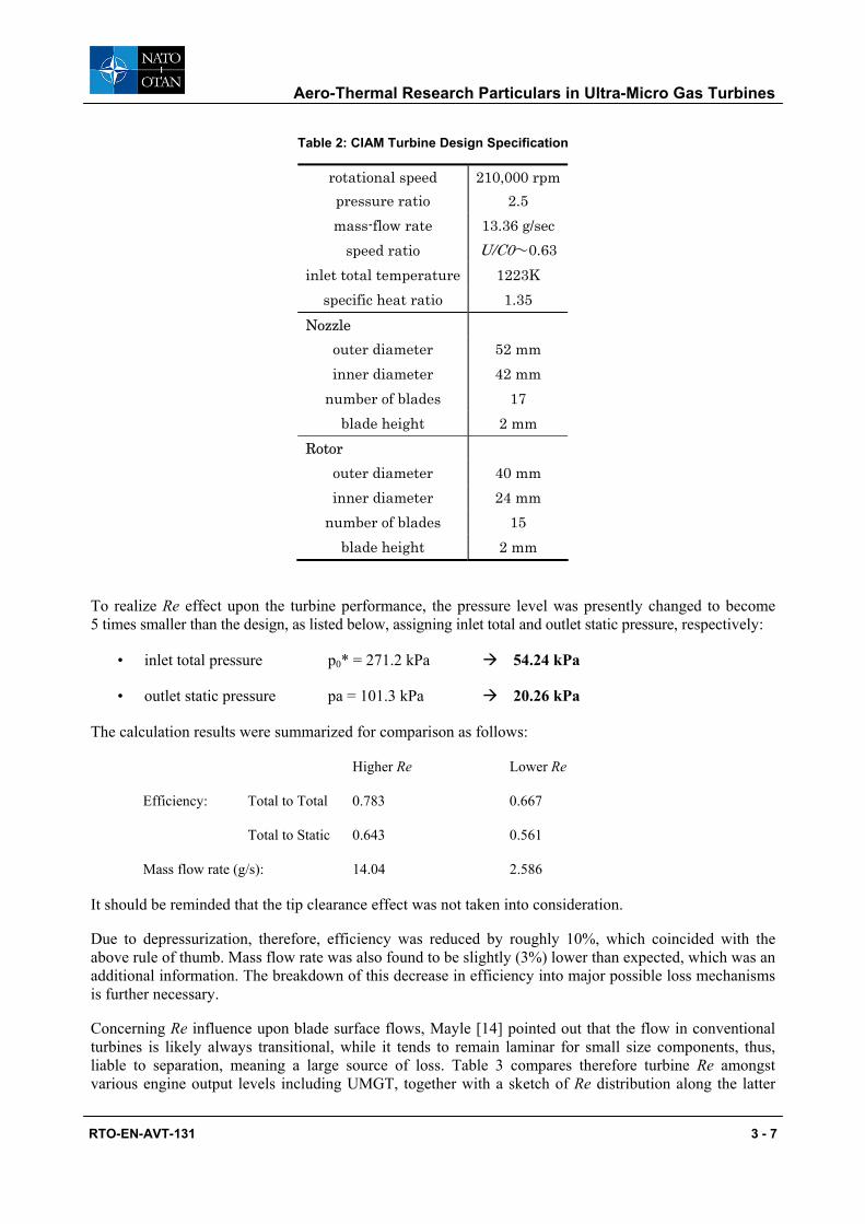
CFD simulation also offers a chance to make a similar check on Re effect, wherefrom the following results were obtained for CIAM designed turbine [4]: The latter major specification is listed in Table 2.
Aero-Thermal Research Particulars in Ultra-Micro Gas Turbines
RTO-EN-AVT-131 3 - 7
Table 2: CIAM Turbine Design Specification
rotational speed 210,000 rpm pressure ratio 2.5 mass-flow rate 13.36 g/sec
speed ratio U/C0~0.63 inlet total temperature 1223K
specific heat ratio 1.35 Nozzle
outer diameter 52 mm inner diameter 42 mm
number of blades 17 blade height 2 mm
Rotor outer diameter 40 mm inner diameter 24 mm
number of blades 15 blade height 2 mm
To realize Re effect upon the turbine performance, the pressure level was presently changed to become 5 times smaller than the design, as listed below, assigning inlet total and outlet static pressure, respectively:
• inlet total pressure p0* = 271.2 kPa 54.24 kPa
• outlet static pressure pa = 101.3 kPa 20.26 kPa
The calculation results were summarized for comparison as follows:
Higher Re Lower Re
Efficiency: Total to Total 0.783 0.667
Total to Static 0.643 0.561
Mass flow rate (g/s): 14.04 2.586
It should be reminded that the tip clearance effect was not taken into consideration.
Due to depressurization, therefore, efficiency was reduced by roughly 10%, which coincided with the above rule of thumb. Mass flow rate was also found to be slightly (3%) lower than expected, which was an additional information. The breakdown of this decrease in efficiency into major possible loss mechanisms is further necessary.
Concerning Re influence upon blade surface flows, Mayle [14] pointed out that the flow in conventional turbines is likely always transitional, while it tends to remain laminar for small size components, thus, liable to separation, meaning a large source of loss. Table 3 compares therefore turbine Re amongst various engine output levels including UMGT, together with a sketch of Re distribution along the latter

Aero-Thermal Research Particulars in Ultra-Micro Gas Turbines
3 - 8 RTO-EN-AVT-131
gas path, whereby it seems that flow separation can occur at any component in UMGT. A possible presence of large flow disturbances like in wake may add difficulty in predicting such flow separation and transition.
Table 3: Representative Reynolds Number at Typical Turbine Engines
2.1.3 Heat Transfer
It has been already pointed out that adiabatic flow condition will never be realized in UMGT, so that isothermal wall condition, due to very low Biot number, is more appropriate within the flow passages. It causes significant influence upon the engine feasibility after all, so that more accurate prediction method needs to be employed for estimating heat transfer coefficients at low Re, in particular, where flow separation is observed to occur. Similarly, it will be crucial, from thermal efficiency point of view, to distinguish a pinpoint component/location within the integrated system, so that appropriate measures can be taken for directing heat fluxes towards the optimum thermal control. In fact, for UMGT system, heat loss at the turbine nozzle has to be kept the minimum, while protection of the compressor from hot components is very effective [4, 15]. Heat transfer effect between turbine and compressor upon cycle efficiency has been discussed elsewhere [16, 17]. Meanwhile, heat generation due to frictional force needs to be watched carefully for the management of air bearings and motor-generator operation with micro clearance at ultra high speed shaft rotation.
2.1.4 Tip Clearance
Clearance between rotor tip and casing wall is inevitable for manufacturing as well as rotor dynamical reason, so that it has to be kept as least as possible to reduce leakage flow. It will be interesting and beneficial to compare turbines and compressors with regard to the mechanism of leakage flow across the blade tip [18], since the relative wall motion against rotor is opposite for turbine and compressor, inasmuch
Fig.1 Micro gas turbine generator cross-section
Turbine Reynolds Number
Turbine Inlet Temperature[K]
Engine Core Air Flow [kg/s]
Mean Turbine Diameter [m]
Category
820,000 1640 340 2.2 Big size
1,200 1600 0.000095 0.005 Ultra-Micro
50,000 1200 0.67 0.15 Micro size
450,000 1520 15 0.2 Small size
750,000 1750 120 0.9 Medium size
1.E+02
1.E+03
1.E+04
1.E+05
1.E+06
COMPONENT POSITION ALONG FLOW PATH
RE
YN
OL
DS
NU
MB
ER
based o
n i
nle
t velo
cit
y &
bla
de c
hord
c ompressorimpe l ler
compressordiffuser
turbine stator
tu rbinerotor
Aero-Thermal Research Particulars in Ultra-Micro Gas Turbines
RTO-EN-AVT-131 3 - 9
as there is fundamental difference in the flow, either accelerating or decelerating. There will be also another way to divert this leakage via employing shroud disk, though excessive stress may result from centrifugal force due to the additional shroud mass.
2.1.5 Geometry Restriction
2D geometry restriction comes from the necessity of MEMS fabrication, which means diversion from applying technical data base so far built up for improving performance of radial turbo-machinery, thus raises severe difficulty in designing rotor blades. According to conventional design practice for radial rotor blades, the meridional velocity is kept almost constant along the gas path for better control in diffusion. This is usually achieved by properly adjusting the flow passage area between two neighbouring blades, e.g. widening blade height towards the inner radius for turbines, while reducing it towards the outer radius for compressors.
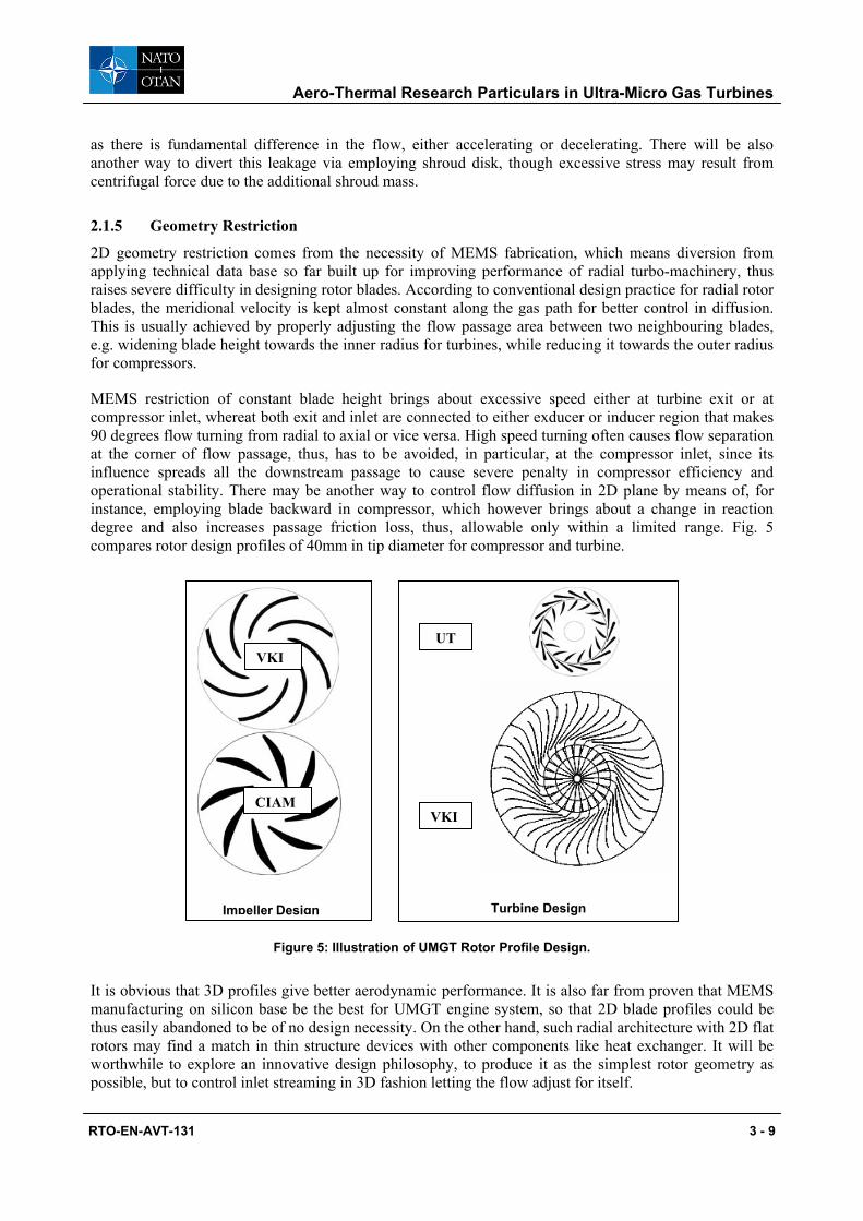
MEMS restriction of constant blade height brings about excessive speed either at turbine exit or at compressor inlet, whereat both exit and inlet are connected to either exducer or inducer region that makes 90 degrees flow turning from radial to axial or vice versa. High speed turning often causes flow separation at the corner of flow passage, thus, has to be avoided, in particular, at the compressor inlet, since its influence spreads all the downstream passage to cause severe penalty in compressor efficiency and operational stability. There may be another way to control flow diffusion in 2D plane by means of, for instance, employing blade backward in compressor, which however brings about a change in reaction degree and also increases passage friction loss, thus, allowable only within a limited range. Fig. 5 compares rotor design profiles of 40mm in tip diameter for compressor and turbine.
Figure 5: Illustration of UMGT Rotor Profile Design.
It is obvious that 3D profiles give better aerodynamic performance. It is also far from proven that MEMS manufacturing on silicon base be the best for UMGT engine system, so that 2D blade profiles could be thus easily abandoned to be of no design necessity. On the other hand, such radial architecture with 2D flat rotors may find a match in thin structure devices with other components like heat exchanger. It will be worthwhile to explore an innovative design philosophy, to produce it as the simplest rotor geometry as possible, but to control inlet streaming in 3D fashion letting the flow adjust for itself.
Turbine Design
Impeller Design
VKI
CIAM
UT
VKI
Aero-Thermal Research Particulars in Ultra-Micro Gas Turbines
3 - 10 RTO-EN-AVT-131
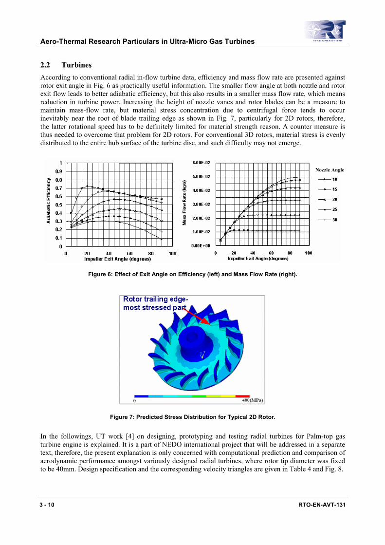
2.2 Turbines According to conventional radial in-flow turbine data, efficiency and mass flow rate are presented against rotor exit angle in Fig. 6 as practically useful information. The smaller flow angle at both nozzle and rotor exit flow leads to better adiabatic efficiency, but this also results in a smaller mass flow rate, which means reduction in turbine power. Increasing the height of nozzle vanes and rotor blades can be a measure to maintain mass-flow rate, but material stress concentration due to centrifugal force tends to occur inevitably near the root of blade trailing edge as shown in Fig. 7, particularly for 2D rotors, therefore, the latter rotational speed has to be definitely limited for material strength reason. A counter measure is thus needed to overcome that problem for 2D rotors. For conventional 3D rotors, material stress is evenly distributed to the entire hub surface of the turbine disc, and such difficulty may not emerge.
Figure 6: Effect of Exit Angle on Efficiency (left) and Mass Flow Rate (right).
Figure 7: Predicted Stress Distribution for Typical 2D Rotor.
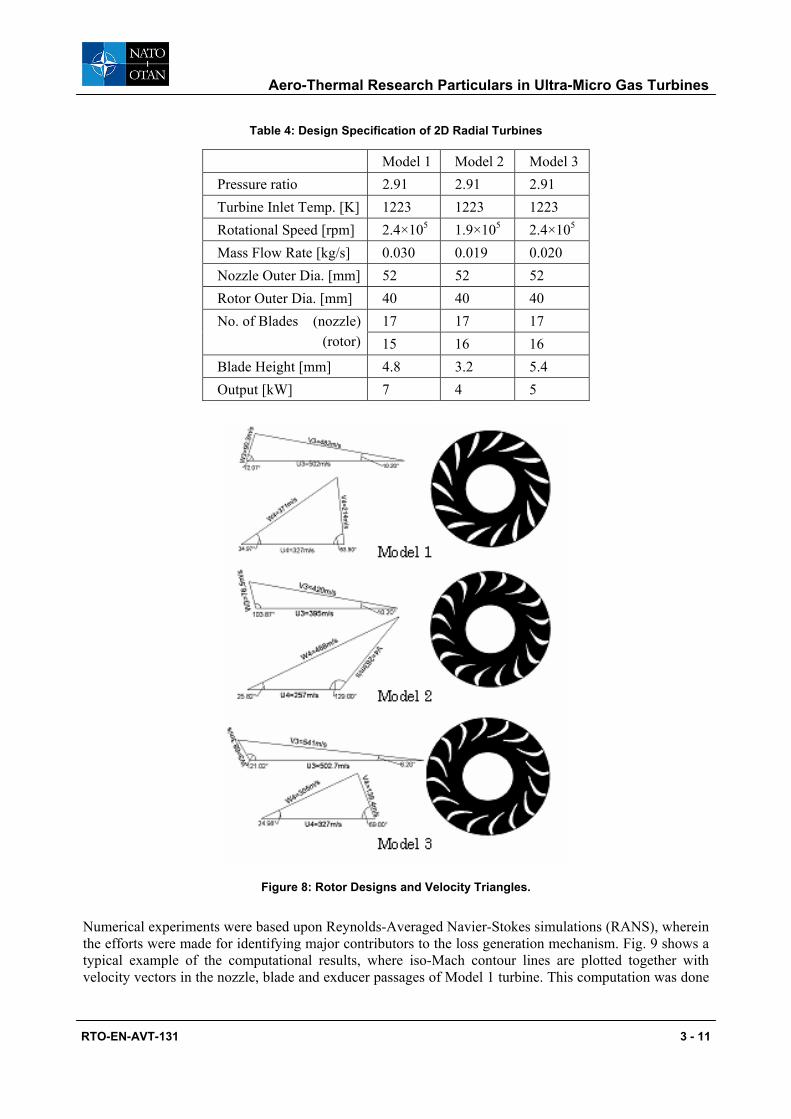
In the followings, UT work [4] on designing, prototyping and testing radial turbines for Palm-top gas turbine engine is explained. It is a part of NEDO international project that will be addressed in a separate text, therefore, the present explanation is only concerned with computational prediction and comparison of aerodynamic performance amongst variously designed radial turbines, where rotor tip diameter was fixed to be 40mm. Design specification and the corresponding velocity triangles are given in Table 4 and Fig. 8.
Nozzle Angle
Aero-Thermal Research Particulars in Ultra-Micro Gas Turbines
RTO-EN-AVT-131 3 - 11
Table 4: Design Specification of 2D Radial Turbines
Model 1 Model 2 Model 3 Pressure ratio 2.91 2.91 2.91 Turbine Inlet Temp. [K] 1223 1223 1223 Rotational Speed [rpm] 2.4×10⁵ 1.9×10⁵ 2.4×10⁵ Mass Flow Rate [kg/s] 0.030 0.019 0.020 Nozzle Outer Dia. [mm] 52 52 52 Rotor Outer Dia. [mm] 40 40 40 No. of Blades (nozzle) 17 17 17 (rotor) 15 16 16 Blade Height [mm] 4.8 3.2 5.4 Output [kW] 7 4 5
Figure 8: Rotor Designs and Velocity Triangles.
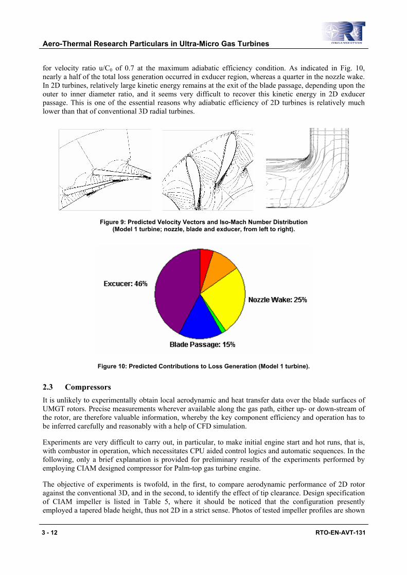
Numerical experiments were based upon Reynolds-Averaged Navier-Stokes simulations (RANS), wherein the efforts were made for identifying major contributors to the loss generation mechanism. Fig. 9 shows a typical example of the computational results, where iso-Mach contour lines are plotted together with velocity vectors in the nozzle, blade and exducer passages of Model 1 turbine. This computation was done
Aero-Thermal Research Particulars in Ultra-Micro Gas Turbines
3 - 12 RTO-EN-AVT-131
for velocity ratio u/C0 of 0.7 at the maximum adiabatic efficiency condition. As indicated in Fig. 10, nearly a half of the total loss generation occurred in exducer region, whereas a quarter in the nozzle wake. In 2D turbines, relatively large kinetic energy remains at the exit of the blade passage, depending upon the outer to inner diameter ratio, and it seems very difficult to recover this kinetic energy in 2D exducer passage. This is one of the essential reasons why adiabatic efficiency of 2D turbines is relatively much lower than that of conventional 3D radial turbines.
Figure 9: Predicted Velocity Vectors and Iso-Mach Number Distribution (Model 1 turbine; nozzle, blade and exducer, from left to right).
Figure 10: Predicted Contributions to Loss Generation (Model 1 turbine).
2.3 Compressors It is unlikely to experimentally obtain local aerodynamic and heat transfer data over the blade surfaces of UMGT rotors. Precise measurements wherever available along the gas path, either up- or down-stream of the rotor, are therefore valuable information, whereby the key component efficiency and operation has to be inferred carefully and reasonably with a help of CFD simulation.
Experiments are very difficult to carry out, in particular, to make initial engine start and hot runs, that is, with combustor in operation, which necessitates CPU aided control logics and automatic sequences. In the following, only a brief explanation is provided for preliminary results of the experiments performed by employing CIAM designed compressor for Palm-top gas turbine engine.
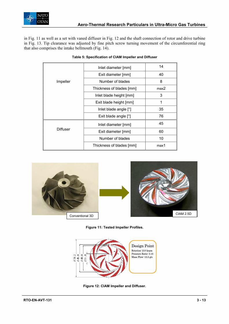
The objective of experiments is twofold, in the first, to compare aerodynamic performance of 2D rotor against the conventional 3D, and in the second, to identify the effect of tip clearance. Design specification of CIAM impeller is listed in Table 5, where it should be noticed that the configuration presently employed a tapered blade height, thus not 2D in a strict sense. Photos of tested impeller profiles are shown
Aero-Thermal Research Particulars in Ultra-Micro Gas Turbines
RTO-EN-AVT-131 3 - 13
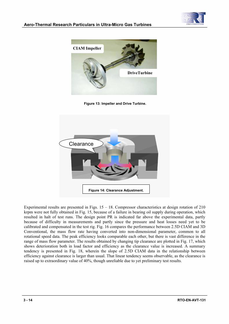
in Fig. 11 as well as a set with vaned diffuser in Fig. 12 and the shaft connection of rotor and drive turbine in Fig. 13. Tip clearance was adjusted by fine pitch screw turning movement of the circumferential ring that also comprises the intake bellmouth (Fig. 14).
Table 5: Specification of CIAM Impeller and Diffuser
Inlet diameter [mm] 14
Exit diameter [mm] 40
Number of blades 8
Thickness of blades [mm] max2
Inlet blade height [mm] 3
Exit blade height [mm] 1
Inlet blade angle [°] 35
Impeller
Exit blade angle [°] 76
Inlet diameter [mm] 45
Exit diameter [mm] 60
Number of blades 10
Diffuser
Thickness of blades [mm] max1
Conventional 3D CIAM 2.5D
Figure 11: Tested Impeller Profiles.
Design Point Rotation: 210 krpm Pressure Ratio: 3.15 Mass Flow: 13.5 g/s
Figure 12: CIAM Impeller and Diffuser.
Aero-Thermal Research Particulars in Ultra-Micro Gas Turbines
3 - 14 RTO-EN-AVT-131
Figure 13: Impeller and Drive Turbine.
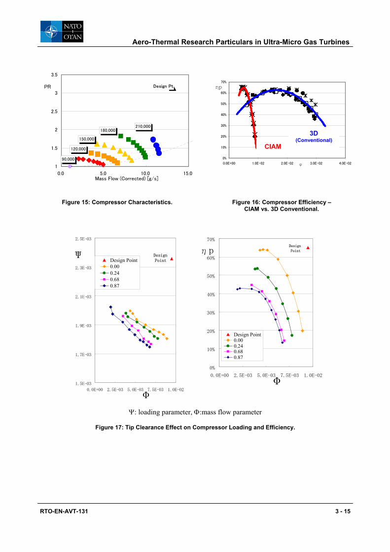
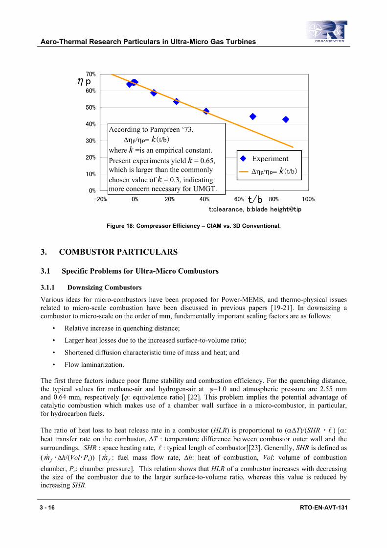
Experimental results are presented in Figs. 15 – 18. Compressor characteristics at design rotation of 210 krpm were not fully obtained in Fig. 15, because of a failure in bearing oil supply during operation, which resulted in halt of test runs. The design point PR is indicated far above the experimental data, partly because of difficulty in measurements and partly since the pressure and heat losses need yet to be calibrated and compensated in the test rig. Fig. 16 compares the performance between 2.5D CIAM and 3D Conventional, the mass flow rate having converted into non-dimensional parameter, common to all rotational speed data. The peak efficiency looks comparable each other, but there is vast difference in the range of mass flow parameter. The results obtained by changing tip clearance are plotted in Fig. 17, which shows deterioration both in load factor and efficiency as the clearance value is increased. A summary tendency is presented in Fig. 18, wherein the slope of 2.5D CIAM data in the relationship between efficiency against clearance is larger than usual. That linear tendency seems observable, as the clearance is raised up to extraordinary value of 40%, though unreliable due to yet preliminary test results.
DriveTurbine
CIAM Impeller
Clearance
Figure 14: Clearance Adjustment.
Aero-Thermal Research Particulars in Ultra-Micro Gas Turbines
RTO-EN-AVT-131 3 - 15
Design Pt
90,000
120,000
150,000
210,000180,000
1
1.5
2
2.5
3
3.5
0.0 5.0 10.0 15.0Mass Flow (Corrected) [g/s]
PR
0%
10%
20%
30%
40%
50%
60%
70%
0.0E+00 1.0E-02 2.0E-02 3.0E-02 4.0E-02φ
ηp
Figure 15: Compressor Characteristics. Figure 16: Compressor Efficiency –CIAM vs. 3D Conventional.
Ψ: loading parameter, Φ:mass flow parameter
Figure 17: Tip Clearance Effect on Compressor Loading and Efficiency.
CIAM
3D (Conventional)
1.5E-03
1.7E-03
1.9E-03
2.1E-03
2.3E-03
2.5E-03
0.0E+00 2.5E-03 5.0E-03 7.5E-03 1.0E-02
Φ
Ψ Design Point 0.000.240.680.87
DesignPoint
0%
10%
20%
30%
40%
50%
60%
70%
0.0E+00 2.5E-03 5.0E-03 7.5E-03 1.0E-02 Φ
ηp
Design Point0.000.240.680.87
Design Point
Aero-Thermal Research Particulars in Ultra-Micro Gas Turbines
3 - 16 RTO-EN-AVT-131
Figure 18: Compressor Efficiency – CIAM vs. 3D Conventional.
3. COMBUSTOR PARTICULARS
3.1 Specific Problems for Ultra-Micro Combustors
3.1.1 Downsizing Combustors
Various ideas for micro-combustors have been proposed for Power-MEMS, and thermo-physical issues related to micro-scale combustion have been discussed in previous papers [19-21]. In downsizing a combustor to micro-scale on the order of mm, fundamentally important scaling factors are as follows:
• Relative increase in quenching distance;
• Larger heat losses due to the increased surface-to-volume ratio;
• Shortened diffusion characteristic time of mass and heat; and
• Flow laminarization.
The first three factors induce poor flame stability and combustion efficiency. For the quenching distance, the typical values for methane-air and hydrogen-air at φ=1.0 and atmospheric pressure are 2.55 mm and 0.64 mm, respectively [φ: equivalence ratio] [22]. This problem implies the potential advantage of catalytic combustion which makes use of a chamber wall surface in a micro-combustor, in particular, for hydrocarbon fuels.
The ratio of heat loss to heat release rate in a combustor (HLR) is proportional to (α∆T)/(SHR・ l ) [α: heat transfer rate on the combustor, ∆T : temperature difference between combustor outer wall and the surroundings, SHR : space heating rate, l : typical length of combustor][23]. Generally, SHR is defined as ( fm& ・∆h/(Vol・Pc)) [ fm& : fuel mass flow rate, ∆h: heat of combustion, Vol: volume of combustion chamber, Pc: chamber pressure]. This relation shows that HLR of a combustor increases with decreasing the size of the combustor due to the larger surface-to-volume ratio, whereas this value is reduced by increasing SHR.
0%
10%
20%
30%
40%
50%
60%
70%
-20% 0% 20% 40% 60% 80% 100%t/bt:clearance, b:blade height@tip
ηp
According to Pampreen ‘73, ∆ηp/ηp= k(t/b)
where k =is an empirical constant. Present experiments yield k = 0.65, which is larger than the commonly chosen value of k = 0.3, indicating more concern necessary for UMGT.
Experiment ∆ηp/ηp= k(t/b)

Aero-Thermal Research Particulars in Ultra-Micro Gas Turbines
RTO-EN-AVT-131 3 - 17
The diffusion characteristic time is represented as L2/D [L: typical length, D: diffusion coefficient]. In downsizing a combustor, the shortened diffusion characteristic time has a crucial effect on the rapid uniformity in concentration distributions near a flame in the combustor. Figure 19 shows a typical example of this characteristic, that is, photographs of a miniature propane flame stabilized on a tube of inner diameter din =0.1 mm near an extinction limit at φ =20. The image on the left is a direct photograph of the flame and the middle image is a schlieren photo. The image on the right is a schlieren photograph of the corresponding unburned pre-mixture jet. It is obvious that the schlieren image region of the flame, that is, the higher temperature region, extends to the far outside the visible flame region and beyond the injector exit. This may be an evidence that a large quantity of heat was transferred by conduction from the flame to its surroundings and also the injector, resulting in substantial heat loss from the flame due to the scale effects of the large surface-to-volume ratio. The schlieren photograph of the unburned pre-mixture also showed that the flow seems to spread rapidly toward the radius just after leaving the exit of the tube. This strongly suggests that some fuel can diffuse to the surroundings before reaching the tip of the flame base due to large diffusion velocity. Therefore, an ultra micro flame in a scale of an ordinary flame zone may dilute its fuel concentration, expand its flame zone, and decrease its temperature, leading to a decrease in flame stability and combustion efficiency of combustors.
0 1 2
Unit: [mm]
Figure 19: Micro Flame Configurations just before Extinction. C3H8/Air, Uje = 1.7 m/s, φe = 20, din = 0.1mm
Left: Direct photograph. Middle: Schlieren Photo with combustion. Right: Schlieren Photo without combustion.
In addition, the flow in ultra-micro combustors should be laminar. In fact, the Reynolds number in the ultra micro-combustor proposed as the original MIT Power-MEMS turbine (pressure ratio: 4, air mass flow rate: 0.15 g/s, combustor height: 1.3 mm, combustor exit temperature 1600 K, fuel mass flow rate
fm& = 7 g/hr) [19] was 100 ~ 200, which is 3 to 4 orders of magnitude lower than those in conventional combustors. This prevents the achievement of rapid mixing between fuel and air and high SHR due to the low transport coefficients related to mass and heat transfer in combustors. In ultra-micro combustors, turbulent combustion, which is employed in most conventional combustors in order to increase SHR, is not possible.
3.1.2 Performance Requirements [24]
An ultra-micro combustor that adequately satisfies the performances required for UMGT has not yet been developed, even when hydrogen has been used. In order to downsize a combustor for gas turbines, the following characteristic factors has to be accomplished in addition to the fundamentally important scaling factors described in 3.1.1:
Aero-Thermal Research Particulars in Ultra-Micro Gas Turbines
3 - 18 RTO-EN-AVT-131
• Low pressure loss;
• Low heat loss to other components;
• High space heating rate (SHR); and
• Premixed combustion.
Reducing the pressure loss in a combustor is particularly important to realizing UMGT with low compressor pressure ratios. Conventional small gas turbines can only allow a pressure loss of 3 to 5%, above which their thermal efficiency is remarkably decreased. Consequently, the Swiss roll burners (see later) are inadequate for the present purpose because of large pressure loss due to their long paths [25].
On the other hand, cycle calculation of the gas turbine that introduced heat losses and transfer from the combustion chamber to compressor and turbine showed that this heat transfer remarkably reduces the thermal efficiency, mainly due to a decrease in the efficiency of compressor and turbine [26]. Reducing the heat transfer from the chamber may be the most important and difficult issue in developing an adequate ultra-micro combustor for UMGT. Separated combustor configuration may be one of the clever ways to improve the performance, however, this issue remains the first priority in future research.
For the combustor of gas turbines, the ratio of chamber volume to air mass flow rate ( am& ) is proportional to the characteristic length. This means that miniaturization of gas turbines requires raising combustor SHR, because of a relative decrease in combustor volume against am& . SHR, defined previously, can be simplified as SHR ~φ・ am& /(Vol・Pc) ~φ・S・v/Vol ~φ・v/ l [φ: equivalence ratio, S: cross section area of combustor, v : mean flow velocity through combustor, l : length of combustor]. When φ of combustors is constant in any kind of gas turbines, SHR ~ v/ l ≅ 1/ bτ . [ bτ : residence time in the combustor]. This shows that bτ depends only on SHR irrelevant to the downsizing. In fact, SHR and bτ estimated for MIT Power-MEMS turbine are the same order as those of a much larger gas turbine combustor with hydrogen fuel [27]. Potential advantages of UMGT are high energy density and high power to weight ratio, which is inversely proportional to characteristic length. Therefore, high SHR in a compact ultra-micro combustor is essential to affecting these advantages.
As mentioned above, in ultra-micro combustors, laminar flow prevents rapid mixing between fuel and air, and when using a micro fuel injector, fuel can diffuse to the surroundings before reaching the flame base. These phenomena suggest that premixed combustion, instead of diffusion combustion, should be selected in ultra-micro combustors. Consequently, in ultra-micro combustors, the realization of high SHR in a laminar flow may be the most challenging requirement among the prerequisites for UMGT.
3.2 Burning Methods of Ultra-Micro Combustors
3.2.1 Approaches
According to the original MIT proposal, the output of Power-MEMS turbine was 16 W that required a combustion chamber volume of 0.04 cm3, a space heating rate of 3.3x10³ MW/(m3・MPa), a combustor pressure loss under 5 % and a combustion efficiency over 99.5 %. The MIT group made two hydrogen/air micro combustors and examined their combustion characteristics. One was a fully premixed combustor with a slit jet configuration, and a volume of 0.191 cm3, and the other was a dual-zone combustor with a primary and dilution-zone configuration and a volume of 0.346 cm3. For the former combustor, the premixed hydrogen-air entered the combustion chamber and then formed the premixed flames held by the recirculation zones at the inlets of the chamber. For the latter, it first burned the premixed hydrogen-air near the stoichiometic condition in the primary zone, and then diluted the combustion products, reducing
Aero-Thermal Research Particulars in Ultra-Micro Gas Turbines
RTO-EN-AVT-131 3 - 19
their temperature to a desired turbine inlet temperature in the dilution zone, which is similar to conventional large-scale combustors. Although the operating range of the dual-zone combustor showed a much broader region than the premixed combustor, it did not provide better combustor efficiencies than the former. As a result, their combustors needed volumes 5 to 9 times as large as that of the original Power-MEMS turbine concept for better flame holding and complete combustion.
In order to improve poor combustion stability and efficiency, the Swiss Roll burner, which applies excess enthalpy flames, has been proposed as micro-scale combustors for Power MEMS devices. This type of burner consists of 2 spirals. The pre-mixture enters through one spiral, forming a flame at the center of the spirals, and the combustion products exit via the other passage, exchanging heat with the incoming pre-mixture. It is well known that the quenching limits can be effectively eliminated through the use of recirculation of thermal energy from the combustion products to preheat the incoming pre-mixture. For gas turbine combustors through which a relatively large amount of air flows, however, there are several disadvantages to be overcome for use of this type of burners; large pressure losses due to their long paths and an unavoidable increase of the total chamber volume including spirals, which prohibits the realization of high space heating rates.
As another approach, catalytic combustors for hydrocarbon fuels have been developed at several research institutes [20]. An obvious advantage of these combustors is that they improve flame stability and increase the combustion efficiency, however the problem generally lies in its low reaction rates resulting in low SHR, and the pre-heating of the incoming reactants. While, the relative increase of surface area and the lower temperatures of the catalytic reaction suggest that micro-scale combustors using catalytic reactions may be easier to be implemented than those using gas phase reactions [20].
3.2.2 Concept of Flat-Flame Combustor [28]
Feasibility relating to the most suitable combustion methods for UMGT was mainly considered from the viewpoint of premixed combustion and high SHR. Reynolds number for ultra-micro combustors will be very small, and thus, the flows in the combustors would be laminar. In addition, for UMGT, the current MEMS technology does not allow the use of a multi-stage, axis-flow and three-dimensional turbo compressor and turbine in high-performance gas turbines. MEMS technology is limited to a two-dimensional centrifugal turbo design with a single stage, causing the ultra-micro combustors to take on a flat disk shape. Under this condition, one of the burning methods to form a laminar flame in a disk-shaped combustor is a flat-flame burner with a porous plate introduced into the incoming pre-mixture. It is well known that, for pre-mixtures with higher burning velocities than the incoming flow velocity through the porous plate, heat losses by conduction to the porous plate lower the burning velocity of the flame until balance is obtained between the new burning velocity with heat loss and the incoming flow velocity, and thus the flat-flame is stabilized on the surface of the porous plate [29]. Therefore the flat-flame is obtained when the burning velocity without heat losses is larger than the incoming flow velocity. If the height of the flat-flame micro combustor is equal to the flame zone thickness, SHR would be remarkably high, thus meeting the level required by UMGT.
3.3 Combustion Characteristics of Flat-Flame Ultra-Micro Combustors [24, 28, 30]
3.3.1 Prototype Combustor
Based on the above concept, a flat-flame ultra-micro combustor employing hydrogen was designed as shown in Fig. 20. The basic dimensions of the combustor were essentially the same as those in the specifications proposed by MIT group [19]. The combustor had a porous plate made of stainless steel with an average filtering accuracy of 5µm and a nozzle made of BN (boron nitride). The height of the combustion chamber with an annular region (5×10.5 mm) was 1 mm, and the volume was 0.067 cm3. After combustion, the burned gas exited radially outward to the atmosphere through a slit with a height of

Aero-Thermal Research Particulars in Ultra-Micro Gas Turbines
3 - 20 RTO-EN-AVT-131
0.3 mm between the nozzle and the quartz tube. Total pressure loss of this combustor was about 5% at the maximum, which satisfied the pressure loss requirement of UMGT. The experiment was performed at atmospheric pressure and room temperature. Air mass flow rates am& were varied from 0.004 to 0.15 g/s, where a typical am& value was determined so as to agree with the air volume flow rate between the present experimental condition and the practical UMGT condition, working at 0.4 MPa and am& = 0.15 g/s. Details of the apparatus and the procedure are described elsewhere [28, 30].
φ10.5φ5
Nozzle
Quartz tube
Combustionchamber
Porous plate
1
Unit:[mm]H2 /Air Premixture
φ10.5φ5
Nozzle
Quartz tube
Combustionchamber
Porous plate
1
Unit:[mm]H2 /Air Premixture
Figure 20: A Schematic of the Flat-Flame Micro-Combustor.
3.3.2 Combustion Characteristics
Flame Appearance
Figure 21(a) shows a typical direct photograph of a hydrogen/air flat-flame formed in the ultra-micro combustor at am& = 0.037 g/s and φ = 0.4. The same flame was photographed using an image intensifier and CCD camera is shown in Fig. 21(b). This flame was very stable, occupied the whole volume of the combustion chamber of 0.067 cm3, and burned well within this small space. It is obvious that the flame zone was almost equal to the combustion chamber volume itself, so that the flame achieved extremely high SHR of 7100 MW/(m3·MPa) at φ =0.4 in a laminar flow. Thus, this flat-flame satisfied UMGT burning method requirement. With increasing φ, the flame remained stable and did not show any change in appearance up to φ =1.0.
BN BN
BN nozzle
Flat-flame
1 0
Unit:[mm]
(a)
(b)
Figure 21: H2/air Flat-Flame Appearance in Ultra-Micro Combustor at am& = 0.037 g/s and ϕ = 0.4.
(a) Direct photograph with exposure time of 180 s. (b) Image intensifier photograph with exposure time of 1/30 s.
Aero-Thermal Research Particulars in Ultra-Micro Gas Turbines
RTO-EN-AVT-131 3 - 21
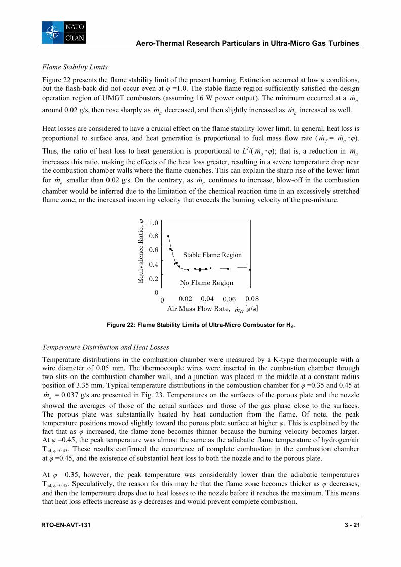
Flame Stability Limits
Figure 22 presents the flame stability limit of the present burning. Extinction occurred at low φ conditions, but the flash-back did not occur even at φ =1.0. The stable flame region sufficiently satisfied the design operation region of UMGT combustors (assuming 16 W power output). The minimum occurred at a am& around 0.02 g/s, then rose sharply as am& decreased, and then slightly increased as am& increased as well.
Heat losses are considered to have a crucial effect on the flame stability lower limit. In general, heat loss is proportional to surface area, and heat generation is proportional to fuel mass flow rate ( fm& = am& ・φ).
Thus, the ratio of heat loss to heat generation is proportional to L2/( am& ・φ); that is, a reduction in am& increases this ratio, making the effects of the heat loss greater, resulting in a severe temperature drop near the combustion chamber walls where the flame quenches. This can explain the sharp rise of the lower limit for am& smaller than 0.02 g/s. On the contrary, as am& continues to increase, blow-off in the combustion chamber would be inferred due to the limitation of the chemical reaction time in an excessively stretched flame zone, or the increased incoming velocity that exceeds the burning velocity of the pre-mixture.
Stable Flame Region
No Flame Region 0
0.2
0.4
0.6
0.8
1.0
0 0.040.02 0.06 0.08Air Mass Flow Rate, ma& [g/s]
Equ
ival
ence
Rat
io, ϕ
Figure 22: Flame Stability Limits of Ultra-Micro Combustor for H2.
Temperature Distribution and Heat Losses
Temperature distributions in the combustion chamber were measured by a K-type thermocouple with a wire diameter of 0.05 mm. The thermocouple wires were inserted in the combustion chamber through two slits on the combustion chamber wall, and a junction was placed in the middle at a constant radius position of 3.35 mm. Typical temperature distributions in the combustion chamber for φ =0.35 and 0.45 at
am& = 0.037 g/s are presented in Fig. 23. Temperatures on the surfaces of the porous plate and the nozzle showed the averages of those of the actual surfaces and those of the gas phase close to the surfaces. The porous plate was substantially heated by heat conduction from the flame. Of note, the peak temperature positions moved slightly toward the porous plate surface at higher φ. This is explained by the fact that as φ increased, the flame zone becomes thinner because the burning velocity becomes larger. At φ =0.45, the peak temperature was almost the same as the adiabatic flame temperature of hydrogen/air Tad,φ=0.45. These results confirmed the occurrence of complete combustion in the combustion chamber at φ =0.45, and the existence of substantial heat loss to both the nozzle and to the porous plate.
At φ =0.35, however, the peak temperature was considerably lower than the adiabatic temperatures Tad,φ=0.35. Speculatively, the reason for this may be that the flame zone becomes thicker as φ decreases, and then the temperature drops due to heat losses to the nozzle before it reaches the maximum. This means that heat loss effects increase as φ decreases and would prevent complete combustion.

Aero-Thermal Research Particulars in Ultra-Micro Gas Turbines
3 - 22 RTO-EN-AVT-131
Tem
pera
ture
, [o C
]
Height from Porous Plate, [mm]
0200400600800
100012001400
0.2 0.4 0.6 0.80 1
Tad, ϕ=0.45
Tad, ϕ=0.35
Figure 23: Temperature Distributions in the Ultra-Micro Combustor for H2 at am& = 0.037 g/s.
Regarding the heat transfer from the flame, the heat loss to the porous plate was assumed not to have fatal effects on the flame behavior, since the porous plate would exchange sufficient heat with the unburned pre-mixture passing through. However, the heat loss to the nozzle clearly caused a temperature drop. The temperature distributions near the nozzle showed that the heat losses to the nozzle were approximately 15% of the heat generation of the hydrogen-air pre-mixture of am& = 0.037 g/s at φ = 0.4. This assumption was quite close to the heat loss estimation from the temperature distribution in the nozzle measured by an additional experiment. These heat losses would not only worsen the combustion efficiency by decreasing the reaction rate, but would also impede self-sustaining operation of gas turbine if about 10% of heat generated were lost through conduction to the compressor and turbine [26].
Combustion Efficiency
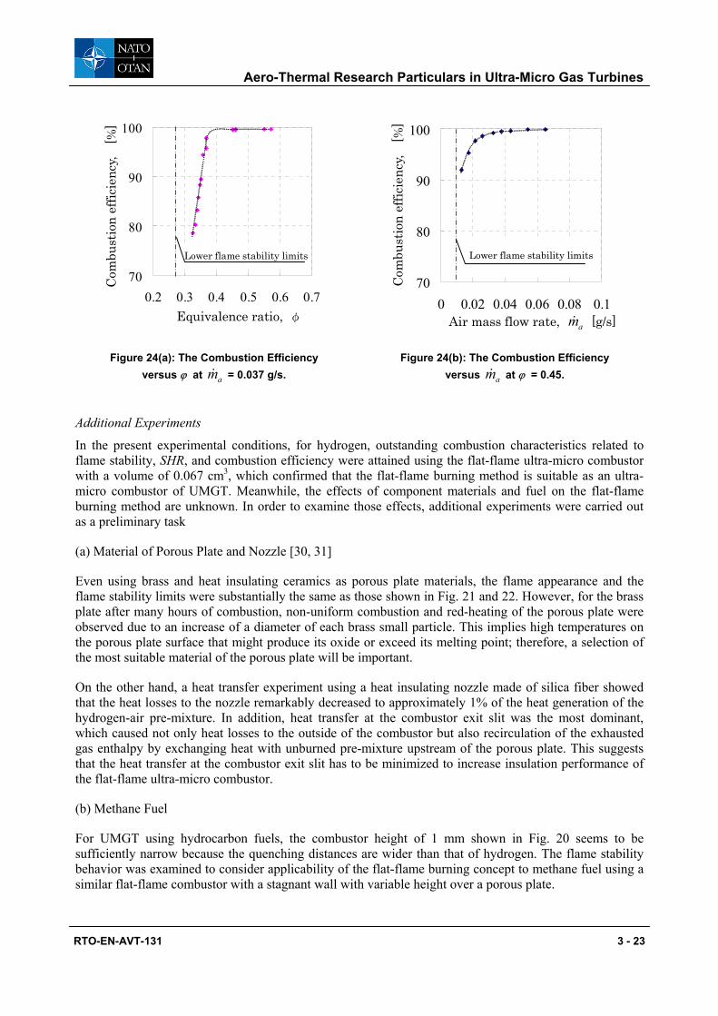
The combustion efficiencies were calculated from the concentrations of unburned hydrogen in the exhausted gas collected via a quartz micro probe of an inner diameter of 0.2 mm at the exit slit, and were analyzed using a hotwire-type semiconductor hydrogen detector. Figure 24(a) shows the combustion efficiency versus φ at a constant am& =0.037 g/s using a brass porous plates. Combustion efficiencies for φ> 0.4 reached more than 99.2 %. In this region, the hydrogen burned completely despite the heat loss transferred to the nozzle, which occurred after the temperature reached the maximum. This suggests that the heat loss to the nozzle had little effect on the flat-flame combustion on the porous plate itself, and only caused a temperature decrease of the exhausted gas after complete combustion. However, measurements indicated that the combustion efficiency decreased drastically for φ< 0.4. This suggests that the flame zone becomes thicker as φ decreases and combustion reactions would be inhibited by heat loss to the nozzle. Finally, the flame quenched due to severe heat loss, precluding a self-sustaining reaction.
On the other hand, the combustion efficiency versus am& , given in Fig. 24(b), also showed that complete combustion was achieved at a wide range of am& , except near the flame stability lower limit. It can be concluded that for hydrogen, the excellence of the flat-flame burning method in a micro combustor for UMGT was confirmed experimentally.
Aero-Thermal Research Particulars in Ultra-Micro Gas Turbines
RTO-EN-AVT-131 3 - 23
70
80
90
100
0.2 0.3 0.4 0.5 0.6 0.7Equivalence ratio, φ
Com
bust
ion
effic
ienc
y, [
%]
Lower flame stability limits
70
80
90
100
0 0.02 0.04 0.06 0.08 0.1
Com
bust
ion
effic
ienc
y, [
%]
Air mass flow rate, am& [g/s]
Lower flame stability limits
Figure 24(a): The Combustion Efficiency versus ϕ at am& = 0.037 g/s.
Figure 24(b): The Combustion Efficiency versus am& at ϕ = 0.45.
Additional Experiments
In the present experimental conditions, for hydrogen, outstanding combustion characteristics related to flame stability, SHR, and combustion efficiency were attained using the flat-flame ultra-micro combustor with a volume of 0.067 cm3, which confirmed that the flat-flame burning method is suitable as an ultra-micro combustor of UMGT. Meanwhile, the effects of component materials and fuel on the flat-flame burning method are unknown. In order to examine those effects, additional experiments were carried out as a preliminary task
(a) Material of Porous Plate and Nozzle [30, 31]
Even using brass and heat insulating ceramics as porous plate materials, the flame appearance and the flame stability limits were substantially the same as those shown in Fig. 21 and 22. However, for the brass plate after many hours of combustion, non-uniform combustion and red-heating of the porous plate were observed due to an increase of a diameter of each brass small particle. This implies high temperatures on the porous plate surface that might produce its oxide or exceed its melting point; therefore, a selection of the most suitable material of the porous plate will be important.
On the other hand, a heat transfer experiment using a heat insulating nozzle made of silica fiber showed that the heat losses to the nozzle remarkably decreased to approximately 1% of the heat generation of the hydrogen-air pre-mixture. In addition, heat transfer at the combustor exit slit was the most dominant, which caused not only heat losses to the outside of the combustor but also recirculation of the exhausted gas enthalpy by exchanging heat with unburned pre-mixture upstream of the porous plate. This suggests that the heat transfer at the combustor exit slit has to be minimized to increase insulation performance of the flat-flame ultra-micro combustor.
(b) Methane Fuel
For UMGT using hydrocarbon fuels, the combustor height of 1 mm shown in Fig. 20 seems to be sufficiently narrow because the quenching distances are wider than that of hydrogen. The flame stability behavior was examined to consider applicability of the flat-flame burning concept to methane fuel using a similar flat-flame combustor with a stagnant wall with variable height over a porous plate.
Aero-Thermal Research Particulars in Ultra-Micro Gas Turbines
3 - 24 RTO-EN-AVT-131
The wall height of the flat-flame combustor played a crucial role in the flame stability due to heat loss and flame stretch effects. When the wall height was 4 mm, dilution by air after burning at φ =0.9 could be effective and SHR could be 650 MW/(m3・MPa). Therefore, this burning method without any catalysis is effective for relatively lower SHR. However, in order to increase SHR with hydrocarbon fuels, catalytic components are necessary to activate surface reaction or to improve flame stability.
4. CFD SIMULATION
4.1 CFD Tools for UMGT Application [34, 35] The flowfields related to UMGT have very small length scale, and geometry quite different from those of conventional turbomachinery. Flow physics that determine the performance of UMGT may be different from larger turbomachinery, so it is not appropriate to apply existent design method directly for the design of UMGT. Millimetre-sized turbomachinery is not yet realized even at component level, so that CFD is inevitably of extensive usage, at least at the initial stage of UMGT development.
The flowfields inside UMGT, however, have several unfavourable features for CFD that:
• Blade shapes are restricted from the requirement of manufacturing process. It is difficult to optimize the blade shape to the same level as conventional turbomachinery, for instance, separation region tends to be larger within the passage.
• Heat transfer from solid walls is quite large.
• Clearance height can be larger than 10 percent of blade height, which is considerably larger than that in conventional turbomachinery.
• Reynolds number is as low as order of 104 and the effect of turbulent transition may not be negligible.
Table 6 summarizes CFD tools used for the design and analysis of UMGT at several organizations. It should be noted that all research organizations apply CFD tools that have been developed for the design and analysis of conventional turbomachinery. By assuming fully turbulent flows, the results are not necessarily satisfactory for the flowfield with turbulent transition, so the last feature, low Re number effect, is still remained for future research. Cares should be taken also in treating the other three features.
Table 6: CFD Tools used for the Design and Analysis of UMGT
organization code grid topology turbulence modelling MIT commercial(FLUENT) unstructured k-ε
VKI TRAF3D structured (H) Baldwin-Lomax CIAM in-house structured (O+H, adaptive) Coakley q-ω
UT in-house structured (H, overset for clearance region)
Baldwin-Lomax
4.2 Characteristics of Quasi Two-Dimensional Turbo-Flows [36, 38, 39] The characteristics of flowfield in a two-dimensional micro turbine are discussed based on an example shown in Fig. 25. Outer diameter of the rotor is 40mm and the design pressure ratio is 2.91 at rotational speed of 24,000RPM. Figure 26 compares the total-pressure loss at each part of turbine, nozzle, rotor, exducer and the exhaust dynamic pressure. The nozzle loss and exhaust dynamic pressure are distinct in the figure. The exducer loss has only minor contribution at lower speed ratio, but it becomes as large as the rotor loss at higher speed ratio.

Aero-Thermal Research Particulars in Ultra-Micro Gas Turbines
RTO-EN-AVT-131 3 - 25
Figure 25: Two-Dimensional Turbine. Figure 26: Total Pressure Loss Components.
Since the turbine flowfield is accelerating, the flowfields at nozzle and rotor are essentially smooth. No separation is observed in nozzle flow, so most of the nozzle loss is attributable to the wake downstream of thick trailing edge. The rotor flow is also clean. Small separation region appears at off-design condition, however since the flowfield is almost two-dimensional, it is not so difficult to design cascade so that separation is suppressed to the minimum. Sizes of turbine do not affect these features, so Re number do not have much influence over the loss at nozzle and rotor other than the change in the boundary layer thickness.
The matter is different in exducer, as it has two particularities peculiar to two-dimensional turbine. The cross section at the inlet of exducer is smaller than that at the inlet of rotor so the flow velocity at exducer is much higher than that of conventional tree-dimensional rotor. The second point is that the flow turns 90 degree from radially inward to axially.
The exducer thus leads to large exhaust loss. Right-angled turning of high-speed exhaust flow induces separation at casing side which is the major source of the exducer loss. So far as turbine is concerned, difficulties mainly come from two-dimensional geometries rather than the size.
The same happens at the inlet of two-dimensional compressor. Figure 28 shows the velocity vector map at the mid-pitch section of CIAM compressor (Fig. 11 – 14). The flow enters the inlet axially and then turns 90 degree toward the impeller. The large curvature of the casing induces separation region.
Figure 27: Velocity Vectors and Relative Mach Contours of a 2D Turbine.
(a) Nozzle (b) Rotor (c) Exducer
Aero-Thermal Research Particulars in Ultra-Micro Gas Turbines
3 - 26 RTO-EN-AVT-131
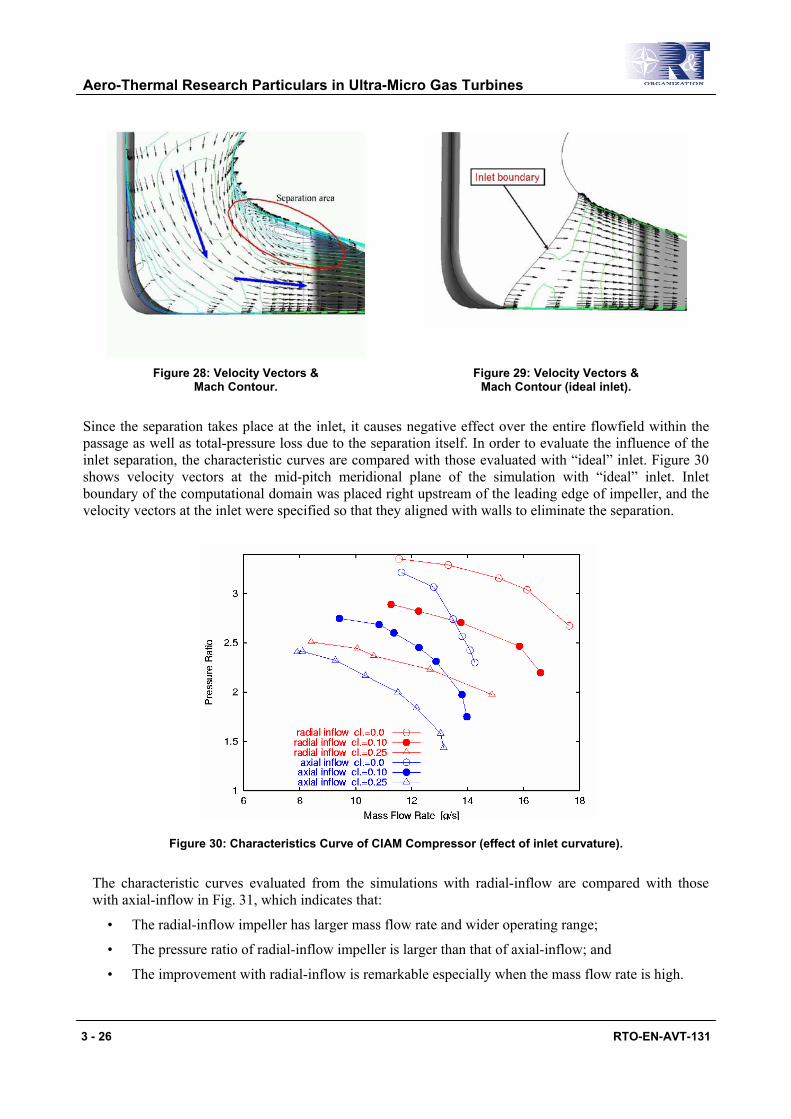
Figure 28: Velocity Vectors & Mach Contour.
Figure 29: Velocity Vectors & Mach Contour (ideal inlet).
Since the separation takes place at the inlet, it causes negative effect over the entire flowfield within the passage as well as total-pressure loss due to the separation itself. In order to evaluate the influence of the inlet separation, the characteristic curves are compared with those evaluated with “ideal” inlet. Figure 30 shows velocity vectors at the mid-pitch meridional plane of the simulation with “ideal” inlet. Inlet boundary of the computational domain was placed right upstream of the leading edge of impeller, and the velocity vectors at the inlet were specified so that they aligned with walls to eliminate the separation.
Figure 30: Characteristics Curve of CIAM Compressor (effect of inlet curvature).
The characteristic curves evaluated from the simulations with radial-inflow are compared with those with axial-inflow in Fig. 31, which indicates that:
• The radial-inflow impeller has larger mass flow rate and wider operating range;
• The pressure ratio of radial-inflow impeller is larger than that of axial-inflow; and
• The improvement with radial-inflow is remarkable especially when the mass flow rate is high.
Aero-Thermal Research Particulars in Ultra-Micro Gas Turbines
RTO-EN-AVT-131 3 - 27
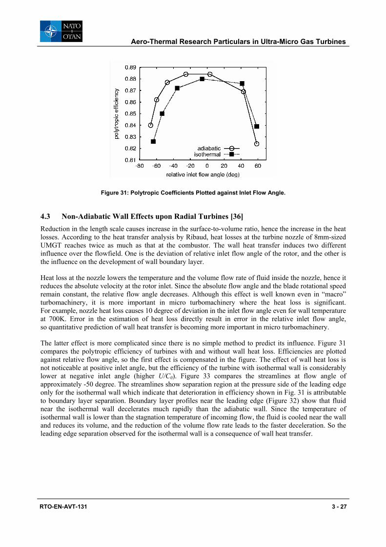
Figure 31: Polytropic Coefficients Plotted against Inlet Flow Angle.
4.3 Non-Adiabatic Wall Effects upon Radial Turbines [36] Reduction in the length scale causes increase in the surface-to-volume ratio, hence the increase in the heat losses. According to the heat transfer analysis by Ribaud, heat losses at the turbine nozzle of 8mm-sized UMGT reaches twice as much as that at the combustor. The wall heat transfer induces two different influence over the flowfield. One is the deviation of relative inlet flow angle of the rotor, and the other is the influence on the development of wall boundary layer.
Heat loss at the nozzle lowers the temperature and the volume flow rate of fluid inside the nozzle, hence it reduces the absolute velocity at the rotor inlet. Since the absolute flow angle and the blade rotational speed remain constant, the relative flow angle decreases. Although this effect is well known even in “macro” turbomachinery, it is more important in micro turbomachinery where the heat loss is significant. For example, nozzle heat loss causes 10 degree of deviation in the inlet flow angle even for wall temperature at 700K. Error in the estimation of heat loss directly result in error in the relative inlet flow angle, so quantitative prediction of wall heat transfer is becoming more important in micro turbomachinery.
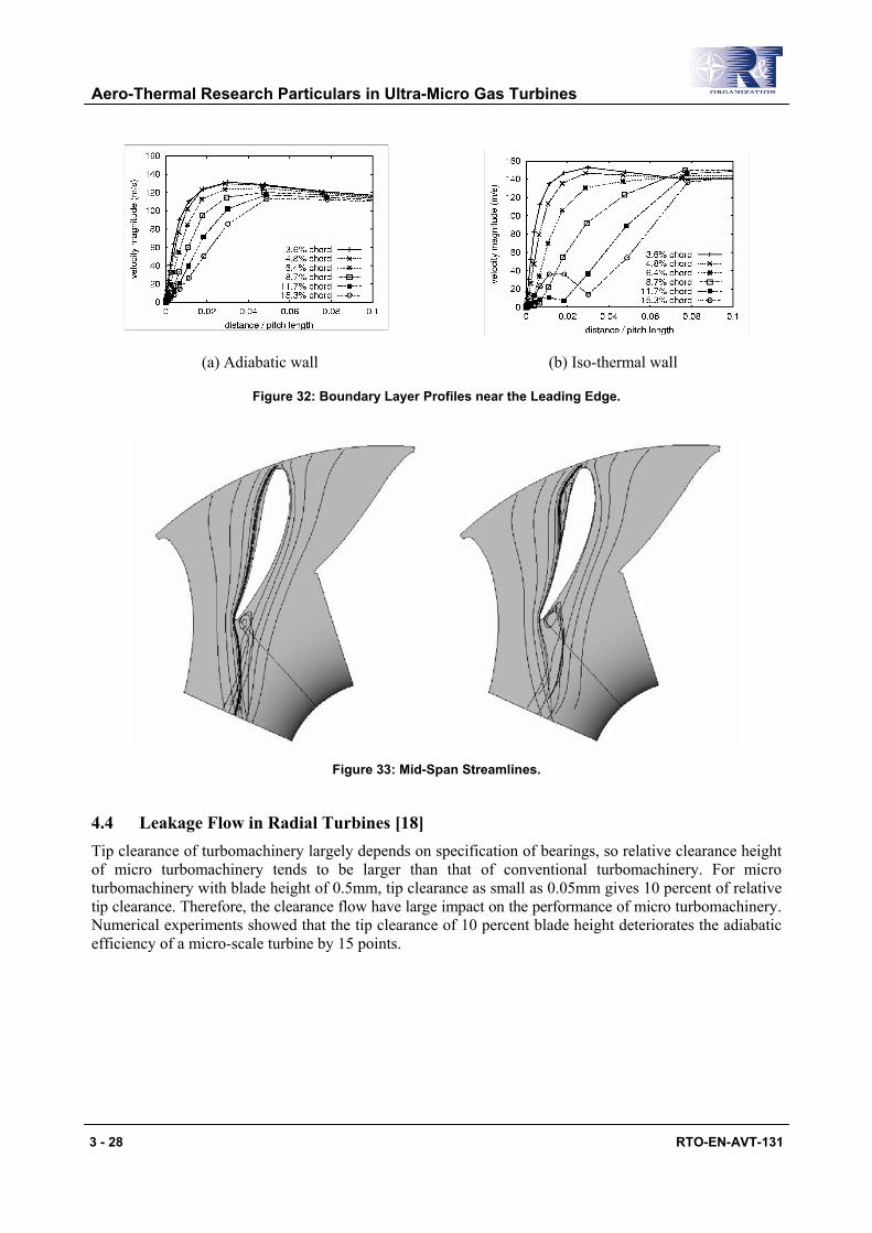
The latter effect is more complicated since there is no simple method to predict its influence. Figure 31 compares the polytropic efficiency of turbines with and without wall heat loss. Efficiencies are plotted against relative flow angle, so the first effect is compensated in the figure. The effect of wall heat loss is not noticeable at positive inlet angle, but the efficiency of the turbine with isothermal wall is considerably lower at negative inlet angle (higher U/C0). Figure 33 compares the streamlines at flow angle of approximately -50 degree. The streamlines show separation region at the pressure side of the leading edge only for the isothermal wall which indicate that deterioration in efficiency shown in Fig. 31 is attributable to boundary layer separation. Boundary layer profiles near the leading edge (Figure 32) show that fluid near the isothermal wall decelerates much rapidly than the adiabatic wall. Since the temperature of isothermal wall is lower than the stagnation temperature of incoming flow, the fluid is cooled near the wall and reduces its volume, and the reduction of the volume flow rate leads to the faster deceleration. So the leading edge separation observed for the isothermal wall is a consequence of wall heat transfer.
Aero-Thermal Research Particulars in Ultra-Micro Gas Turbines
3 - 28 RTO-EN-AVT-131
(a) Adiabatic wall (b) Iso-thermal wall
Figure 32: Boundary Layer Profiles near the Leading Edge.
Figure 33: Mid-Span Streamlines.
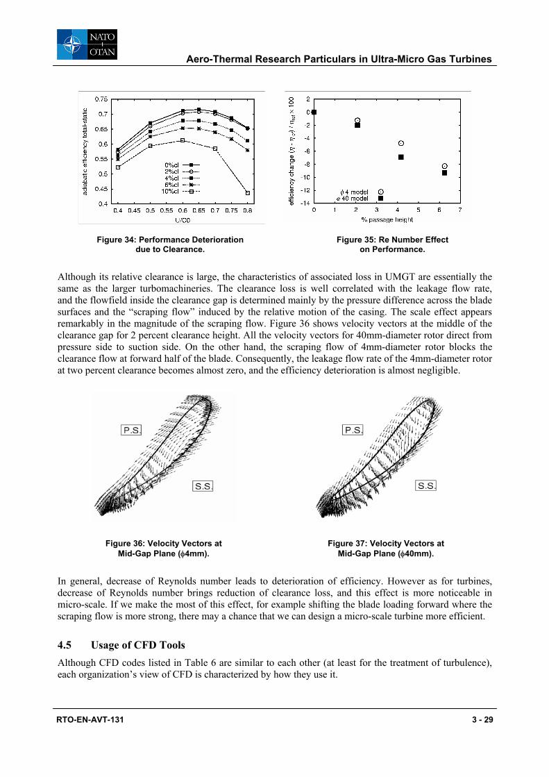
4.4 Leakage Flow in Radial Turbines [18] Tip clearance of turbomachinery largely depends on specification of bearings, so relative clearance height of micro turbomachinery tends to be larger than that of conventional turbomachinery. For micro turbomachinery with blade height of 0.5mm, tip clearance as small as 0.05mm gives 10 percent of relative tip clearance. Therefore, the clearance flow have large impact on the performance of micro turbomachinery. Numerical experiments showed that the tip clearance of 10 percent blade height deteriorates the adiabatic efficiency of a micro-scale turbine by 15 points.
Aero-Thermal Research Particulars in Ultra-Micro Gas Turbines
RTO-EN-AVT-131 3 - 29
Figure 34: Performance Deterioration due to Clearance.
Figure 35: Re Number Effect on Performance.
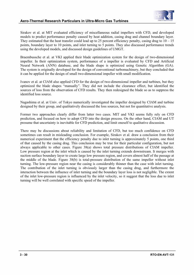
Although its relative clearance is large, the characteristics of associated loss in UMGT are essentially the same as the larger turbomachineries. The clearance loss is well correlated with the leakage flow rate, and the flowfield inside the clearance gap is determined mainly by the pressure difference across the blade surfaces and the “scraping flow” induced by the relative motion of the casing. The scale effect appears remarkably in the magnitude of the scraping flow. Figure 36 shows velocity vectors at the middle of the clearance gap for 2 percent clearance height. All the velocity vectors for 40mm-diameter rotor direct from pressure side to suction side. On the other hand, the scraping flow of 4mm-diameter rotor blocks the clearance flow at forward half of the blade. Consequently, the leakage flow rate of the 4mm-diameter rotor at two percent clearance becomes almost zero, and the efficiency deterioration is almost negligible.
Figure 36: Velocity Vectors at Mid-Gap Plane (φ4mm).
Figure 37: Velocity Vectors at Mid-Gap Plane (φ40mm).
In general, decrease of Reynolds number leads to deterioration of efficiency. However as for turbines, decrease of Reynolds number brings reduction of clearance loss, and this effect is more noticeable in micro-scale. If we make the most of this effect, for example shifting the blade loading forward where the scraping flow is more strong, there may a chance that we can design a micro-scale turbine more efficient.
4.5 Usage of CFD Tools Although CFD codes listed in Table 6 are similar to each other (at least for the treatment of turbulence), each organization’s view of CFD is characterized by how they use it.
Aero-Thermal Research Particulars in Ultra-Micro Gas Turbines
3 - 30 RTO-EN-AVT-131
Sirakov et al. at MIT evaluated efficiency of miscellaneous radial impellers with CFD, and developed models to predict performance penalty caused by heat addition, casing drag and channel boundary layer. They estimated that the heat transfer could lead up to 25 percent efficiency penalty, casing drag to 10 – 15 points, boundary layer to 10 points, and inlet turning to 5 points. They also discussed performance trends using the developed models, and discussed design guidelines of UMGT.
Braembussche et al. at VKI applied their blade optimization system for the design of two-dimensional impeller. In their optimization system, performance of a impeller is evaluated by CFD and Artificial Neural Network (ANN) database, and the blade shape is optimized using Genetic Algorithm (GA). The system is originally developed for the design of conventional turbomachinery, but they concluded that it can be applied for the design of small two-dimensional impeller with small modification.
Ivanov et al. at CIAM also applied CFD for the design of two-dimensional impeller and turbines, but they optimized the blade shapes “manually”. They did not include the clearance effect, but identified the sources of loss from the observation of CFD results. They then redesigned the blade so as to suppress the identified loss source.
Nagashima et al. at Univ. of Tokyo numerically investigated the impeller designed by CIAM and turbine designed by their group, and qualitatively discussed the loss sources, but not for quantitative analysis.
Former two approaches clearly differ from latter two cases. MIT and VKI seems fully rely on CFD prediction, and focused on how to adopt CFD into the design process. On the other hand, CIAM and UT presume that uncertainty is inevitable for CFD prediction, and limit oneself to qualitative discussion.
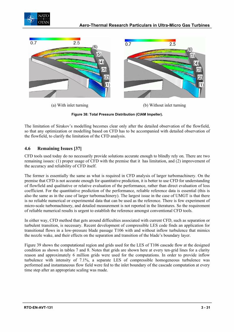
There may be discussions about reliability and limitation of CFD, but too much confidence on CFD sometimes can result in misleading conclusion. For example, Sirakov et al. draw a conclusion from their numerical experiment that the efficiency penalty due to inlet turning is approximately 5 points, one third of that caused by the casing drag. This conclusion may be true for their particular configuration, but not always applicable to other cases. Figure 38(a) shows total pressure distributions of CIAM impeller. Low pressure region at the inlet which is caused by the inlet turning extends downstream. It merges with suction surface boundary layer to create large low pressure region, and covers almost half of the passage at the middle of the blade. Figure 38(b) is total-pressure distribution of the same impeller without inlet turning. The low-pressure region near the casing is considerably thinner than the case with inlet turning. The contribution of the inlet turning is obviously larger than the casing drug, and furthermore the interaction between the influence of inlet turning and the boundary layer loss is not negligible. The extent of the inlet low-pressure region is influenced by the inlet velocity, so it suggest that the loss due to inlet turning will be well correlated with specific speed of the impeller.
Aero-Thermal Research Particulars in Ultra-Micro Gas Turbines
RTO-EN-AVT-131 3 - 31
(a) With inlet turning (b) Without inlet turning
Figure 38: Total Pressure Distribution (CIAM Impeller).
The limitation of Sirakov’s modelling becomes clear only after the detailed observation of the flowfield, so that any optimization or modelling based on CFD has to be accompanied with detailed observation of the flowfield, to clarify the limitation of the CFD analysis.
4.6 Remaining Issues [37] CFD tools used today do no necessarily provide solutions accurate enough to blindly rely on. There are two remaining issues: (1) proper usage of CFD with the premise that it has limitation, and (2) improvement of the accuracy and reliability of CFD itself.
The former is essentially the same as what is required in CFD analysis of larger turbomachinery. On the premise that CFD is not accurate enough for quantitative prediction, it is better to use CFD for understanding of flowfield and qualitative or relative evaluation of the performance, rather than direct evaluation of loss coefficient. For the quantitative prediction of the performance, reliable reference data is essential (this is also the same as in the case of larger turbomachinery). The largest issue in the case of UMGT is that there is no reliable numerical or experimental data that can be used as the reference. There is few experiment of micro-scale turbomachinery, and detailed measurement is not reported in the literatures. So the requirement of reliable numerical results is urgent to establish the reference amongst conventional CFD tools.
In either way, CFD method that gets around difficulties associated with current CFD, such as separation or turbulent transition, is necessary. Recent development of compressible LES code finds an application for transitional flows in a low-pressure blade passage T106 with and without inflow turbulence that mimics the nozzle wake, and their effects on the separation and transition of the blade’s boundary layer.
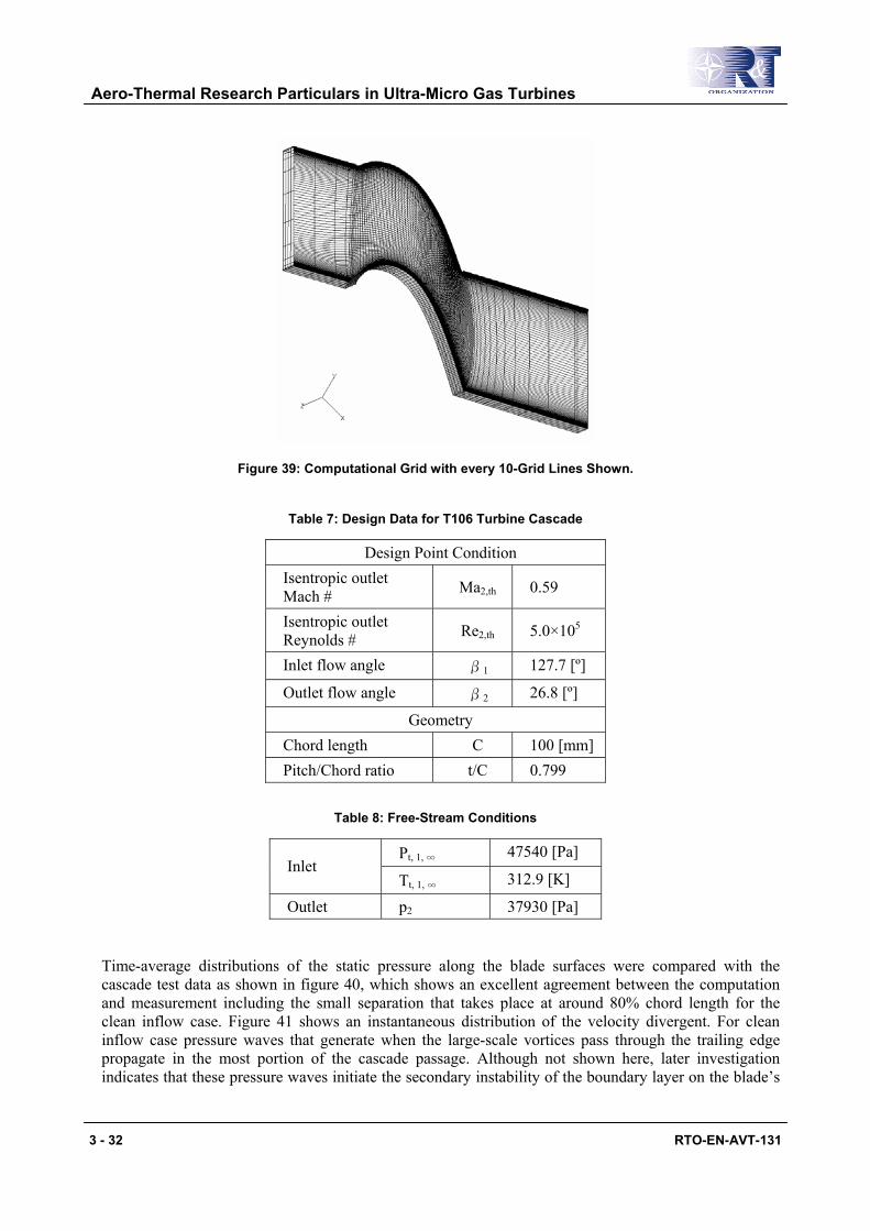
Figure 39 shows the computational region and grids used for the LES of T106 cascade flow at the designed condition as shown in tables 7 and 8. Notes that grids are shown here at every ten-grid lines for a clarity reason and approximately 6 million grids were used for the computations. In order to provide inflow turbulence with intensity of 7.1%, a separate LES of compressible homogeneous turbulence was performed and instantaneous flow field were fed to the inlet boundary of the cascade computation at every time step after an appropriate scaling was made.
Aero-Thermal Research Particulars in Ultra-Micro Gas Turbines
3 - 32 RTO-EN-AVT-131
Figure 39: Computational Grid with every 10-Grid Lines Shown.
Table 7: Design Data for T106 Turbine Cascade
Design Point Condition Isentropic outlet Mach # Ma2,th 0.59
Isentropic outlet Reynolds # Re2,th 5.0×10⁵
Inlet flow angle β1 127.7 [º]
Outlet flow angle β2 26.8 [º]
Geometry Chord length C 100 [mm] Pitch/Chord ratio t/C 0.799
Table 8: Free-Stream Conditions
Pt, 1, ∞ 47540 [Pa] Inlet
Tt, 1, ∞ 312.9 [K]
Outlet p2 37930 [Pa]
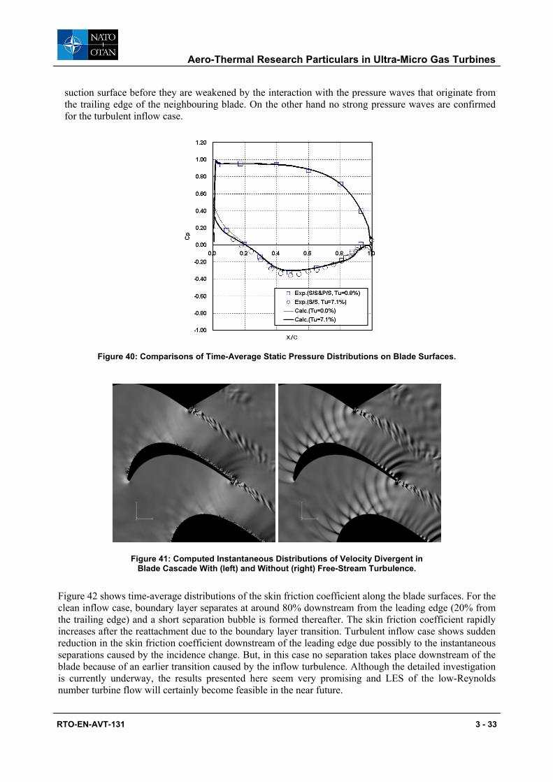
Time-average distributions of the static pressure along the blade surfaces were compared with the cascade test data as shown in figure 40, which shows an excellent agreement between the computation and measurement including the small separation that takes place at around 80% chord length for the clean inflow case. Figure 41 shows an instantaneous distribution of the velocity divergent. For clean inflow case pressure waves that generate when the large-scale vortices pass through the trailing edge propagate in the most portion of the cascade passage. Although not shown here, later investigation indicates that these pressure waves initiate the secondary instability of the boundary layer on the blade’s
Aero-Thermal Research Particulars in Ultra-Micro Gas Turbines
RTO-EN-AVT-131 3 - 33
suction surface before they are weakened by the interaction with the pressure waves that originate from the trailing edge of the neighbouring blade. On the other hand no strong pressure waves are confirmed for the turbulent inflow case.
Figure 40: Comparisons of Time-Average Static Pressure Distributions on Blade Surfaces.
Figure 41: Computed Instantaneous Distributions of Velocity Divergent in Blade Cascade With (left) and Without (right) Free-Stream Turbulence.
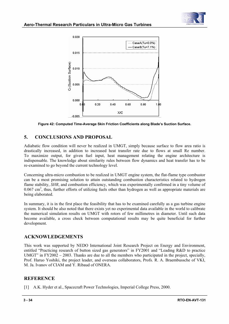
Figure 42 shows time-average distributions of the skin friction coefficient along the blade surfaces. For the clean inflow case, boundary layer separates at around 80% downstream from the leading edge (20% from the trailing edge) and a short separation bubble is formed thereafter. The skin friction coefficient rapidly increases after the reattachment due to the boundary layer transition. Turbulent inflow case shows sudden reduction in the skin friction coefficient downstream of the leading edge due possibly to the instantaneous separations caused by the incidence change. But, in this case no separation takes place downstream of the blade because of an earlier transition caused by the inflow turbulence. Although the detailed investigation is currently underway, the results presented here seem very promising and LES of the low-Reynolds number turbine flow will certainly become feasible in the near future.
Aero-Thermal Research Particulars in Ultra-Micro Gas Turbines
3 - 34 RTO-EN-AVT-131
Figure 42: Computed Time-Average Skin Friction Coefficients along Blade’s Suction Surface.
5. CONCLUSIONS AND PROPOSAL
Adiabatic flow condition will never be realized in UMGT, simply because surface to flow area ratio is drastically increased, in addition to increased heat transfer rate due to flows at small Re number. To maximize output, for given fuel input, heat management relating the engine architecture is indispensable. The knowledge about similarity rules between flow dynamics and heat transfer has to be re-examined to go beyond the current technology level.
Concerning ultra-micro combustion to be realized in UMGT engine system, the flat-flame type combustor can be a most promising solution to attain outstanding combustion characteristics related to hydrogen flame stability, SHR, and combustion efficiency, which was experimentally confirmed in a tiny volume of 0.067 cm3, thus, further efforts of utilizing fuels other than hydrogen as well as appropriate materials are being elaborated.
In summary, it is in the first place the feasibility that has to be examined carefully as a gas turbine engine system. It should be also noted that there exists yet no experimental data available in the world to calibrate the numerical simulation results on UMGT with rotors of few millimetres in diameter. Until such data become available, a cross check between computational results may be quite beneficial for further development.
ACKNOWLEDGEMENTS
This work was supported by NEDO International Joint Research Project on Energy and Environment, entitled “Practicing research of button sized gas generators” in FY2001 and “Leading R&D to practice UMGT” in FY2002 – 2003. Thanks are due to all the members who participated in the project, specially, Prof. Haruo Yoshiki, the project leader, and overseas collaborators, Profs. R. A. Braembussche of VKI, M. Ja. Ivanov of CIAM and Y. Ribaud of ONERA.
REFERENCE
[1] A.K. Hyder et al., Spacecraft Power Technologies, Imperial College Press, 2000.
Aero-Thermal Research Particulars in Ultra-Micro Gas Turbines
RTO-EN-AVT-131 3 - 35
[2] Epstein, A.H. et al., “Micro-Heat Engines, Gas Turbines, and Rocket Engines – the MIT Microengine Project”, AIAA Paper 97-1773, 1997.
[3] NTS Seminar, Micro Gas Turbines, R&D and Prospects, ISBN 4-900830-73-9, p. 26, 2001 (in Japanese).
[4] NEDO International Research Project, Leading R&D to practice Ultra Micro Gas Turbines, Report 2002.
[5] Isomura, K. et al, Research on Micro-Machine Gas Turbines -1st Rep. Feasibility Study-, IHI Tech. J., Vol. 42, 3, pp. 177-183, 2002.
[6] Epstein, A.H., “Millimeter-Scale, Micro-Electro-Mechanical-Systems Gas Turbine Engines”, ASME J. Eng. Gas Turbines Power, Vol. 126, pp. 205-226, 2004.
[7] Yamane, T., Nagashima, T., “A Newmerical Study on Three Dimensional Viscous Flows of a Radial-Inflow Turbiner”, Proceedings of 10th International Symposium on Air Breathing Engines, Vol. 1, 1991, pp. 439-446 (ISABE 1991).
[8] Eckardt, D., “Detailed Flow Investigations within a High Speed Centrifugal Compressor Impeller”, ASME J. Fluids Engineering, Vol. 98, pp. 390-402, 1976.
[9] Krain, H., “A Study on Centrifugal Impeller and Diffuser Flow”, ASME J. Engineering for Power, Vol. 103, pp. 688-697, 1981.
[10] Yamane, T., Fujita, H., Nagashima, T., “An Investigation of Impeller and Diffuser Interaction in a Transonic Centrifugal Compressor”, Unsteady Aerodynamics and Aeroelasticity of Turbomachines, 1995, pp. 499-513 (ISUAAT 1995).
[11] Yamane, T., Nagashima, T., “Flow Choking and Shock Wave Structure at Diffuser Vanes in a High Speed Centrifugal Impeller”, Proceedings of 12th International Symposium on Air Breathing Engines, Vol. 1, 1995, pp. 135-145 (ISUAAT 1997).
[12] Yamane, T., Nagashima, T., “High Speed Centrifugal Impeller and Diffuser Interaction near Stall Conditions”, Unsteady Aerodynamics and Aeroelasticity of Turbomachines, 1998, pp. 259-271 (ISABE 1999).
[13] Yamane, T., Gu, C., Nagashima, T., “Unsteady Flow Simulations of Centrifugal Impeller and Diffuser Interactions”, Proceedings of 14th International Symposium on Air Breathing Engines, 1999.
[14] Mayle, R.E., “The Role of Laminar-Turbulent Transition in Gas Turbine Engines”, ASME J. Turbomachinery, 1991 IGTI Scholar Lecture, Vol. 113, pp. 509-537, 1991.
[15] Ribaud, Y., Internal Heat Mixing and External Heat Losses in an Ultra Micro Turbine, Proceedings IGTC2003Tokyo OS-109, 2003.
[16] Nagashima, T. and Tsuji Y., “A note on UMGT cycle performance due to heat transfer between turbine and compressor” J. GTSJ, Vol. 30, No.4, pp. 308-311, 2002 (in Japanese).
[17] Van den Braembussche, R.A. et al., “Heat and Power Balance in Micro Gasturbine Rotors”, Tech. Digest, PowerMEMS 2004, pp. 84-87, 2004.
Aero-Thermal Research Particulars in Ultra-Micro Gas Turbines
3 - 36 RTO-EN-AVT-131
[18] Watanabe, N., Teramoto, S. and Nagashima, T., “Numerical Analysis of Tip Clearance Effects in a Micro Radial Inflow Turbine”, Proceedings AJCPP2004, 2004.
[19] Waitz, I.A., Gauba, G., Tzeng, Y.S., “Combustors for Micro-Gas Turbine Engines”, Journal of Fluids Engineering, 120, 109-117 (1998).
[20] Pello, A.C.F., “Micro-Power Generation Using Combustion: Issues and Approaches”, Proceedings of the Combustion Institute, 29, 883-899 (2002).
[21] Yuasa, S., “Current State and Problems of Ultra-Micro Hydrogen Combustors” (in Japanese), Journal of the Gas Turbine Society of Japan, 29(4), 247-254 (2001).
[22] Kanury, A.M., Introduction to Combustion Phenomena, Gordon and Breach Science Publishers, New York, (1982).
[23] Yuasa, S., et al, “Specified Problems and Development of Prototypes of Ultra-micro Combustors”, 17th International Symposium on Airbreathing Engines, ISABE 2005 (2005) (accepted).
[24] Yuasa, S., et al, “Concept and Combustion Characteristics of Ultra-micro Combustors with Premixed Flame”, Proceedings of the Combustion Institute, 30, 2455-2462 (2004).
[25] Weinberg, F.J., “The First Half Million Years of Combustion Research and Today’s Burning Problems”, Proceedings of the Combustion Institute, 15, 1-17 (1975).
[26] Oshimi, K., Yuasa, S., “The effects of the Heat Transfer between the Components of Ultra Micro Gas Turbine on Its performance” (in Japanese), Journal of the Gas Turbine Society of Japan, 31(5), 340-345 (2003).
[27] Yuasa, S., et al., “Development of Hydrogen-fueled Micro Gas Turbine System” (in Japanese), Journal of the Gas Turbine Society of Japan, 15(59), 122-128 (1987).
[28] Yuasa, S., Oshimi, K., “Concept and Experiment of a Flat-flame Micro-combustor for Ultra Micro Gas Turbine”, 38th AIAA/ASME/SAE/ASEE Joint Propulsion Conference & Exhibition, AIAA-2002-3771 (2002).
[29] Fristrom, R.M., Westenberg, A. A., Flame Structure, McGraw-Hill, New York, (1965).
[30] Oshimi, K., Yuasa, S., “Combustion Characteristics of a Flat-flame Micro-combustor for Ultra Micro Gas Turbine”, 16th International Symposium on Airbreathing Engines, ISABE 2003-1220 (2003).
[31] Oshimi, K., Yuasa, S., “Evaluation of Heat Transfer in Flat-flame Ultra-micro Combustor for Ultra Micro Gus Turbine” (in Japanese), Journal of the Gus Turbine Society of Japan, 33 (2005) (accepted).
[32] Sirakov, B., Gong, Y. Epstein, A. and Tan, C., “Design and Characterization of Micro-Compressor Impellers”, ASME Turbo Expo 2004, ASME GT2004-53332 (2004).
[33] Gong, Y., Sirakov, B., Epstein, A. and Tan, C., “Aerothermodynamics of Micro-Turbomachinery”, ASME Turbo Expo 2004, ASME GT2004-53877 (2004).
[34] Braembussche, R., Islek, A. and Alsalihi, Z., “Aerothermal Optimization of Micro-gasturbine Compressor Including heat Transfer”, Proceedings of the International Gas Turbine Congress 2003, IGTC2003Tokyo OS-101 (2003).
Aero-Thermal Research Particulars in Ultra-Micro Gas Turbines
RTO-EN-AVT-131 3 - 37
[35] Gaydamaka, I., Efimov, A., Ivanov, M., Ivanov, O., Nigmatullin, R. and Ogarko, N., “Some Aerodynamic Performances of Small Size Compressor and Turbine Stages”, Proceedings of the International Gas Turbine Congress 2003, IGTC2003Tokyo OS-105 (2003).
[36] Watanabe, N., Teramoto, S. and Nagashima, T., “Numerical Analysis of 2.5 Dimensional Geometry Turbine Performance”, Proceedings of the International Gas Turbine Congress 2003, IGTC2003Tokyo OS-104 (2003).
[37] Matsuura, K. and Kato, C., “Large Eddy Simulation of Compressible Transitional Cascade Flows” Transactions of the Japan Society for Mechanical Engineering Vol. 70, No. 700, pp. 3066 (2004) (in Japanese).
[38] Matsuura, K., Kato, C., Yoshiki, H., Matsuo, E., Ikeda, H., Nishimura, R., “Prototyping of Small-sized Two-dimensional Radial Turbines”, Proceedings of the International Gas Turbine Congress 2003, IGTC2003Tokyo OS-107 (2003).
[39] Sato, R., Yamaguchi, K., Teramoto, S. and Nagashima, T., “Numerical and Experimental Study of Ultra-Micro Quasi-two-dimensional Centrifugal Compressor”, Proceedings of Asian Joint Conferences on Propulsion and Power, AJCPP-A2093 (2005).

Aero-Thermal Research Particulars in Ultra-Micro Gas Turbines
3 - 38 RTO-EN-AVT-131